Embed Size (px)
Citation preview

Copyright 2005International Electronics, Inc.
Hub Manager Professional 7Software User Manual \ Help File6045011, Rev 7.1, D1
Hub Manager Professional 7
International Electronics, Inc.Hub Manager Professional 7
Access Control SoftwareUser Manual
For Support Please Contact:
Company Name: ________________________________
Phone: _______________________________________
This equipment is designed to be installed and serviced bysecurity and lock industry professionals.


IContents
Table of ContentsChapter 1: Using Online Help
....................................................................................... 11 Using Help
Chapter 2: Foreword
Chapter 3: Installation
....................................................................................... 71 Installation
Chapter 4: Overview
....................................................................................... 111 General Overview
....................................................................................... 192 Initial Set Up
....................................................................................... 223 Menu System
....................................................................................... 244 Running the software
....................................................................................... 265 System Setup Tasklist
....................................................................................... 286 PDA Software
....................................................................................... 387 Uninstall
Chapter 5: System
....................................................................................... 401 System Menu
....................................................................................... 402 System Manager
....................................................................................... 553 Login
....................................................................................... 564 Logout
....................................................................................... 565 Change Login Password
....................................................................................... 566 Exit
Chapter 6: Database
....................................................................................... 581 Database Menu
....................................................................................... 582 Operators
....................................................................................... 603 Operator Wizard
....................................................................................... 614 Sites
....................................................................................... 63Site Wizard
....................................................................................... 64Serial Connection
....................................................................................... 64PDA Connection
....................................................................................... 64LAN/WAN Connection
....................................................................................... 70Dynamic IP Address
....................................................................................... 73Dynamic IP Address, non-expiring lease
....................................................................................... 73Static IP Address
....................................................................................... 79Modem Connection
....................................................................................... 81Managing Stand-Alone Controllers
....................................................................................... 825 TimeZones
IEI Hub Manager Professional 7 II
IEI Hub Manager Professional 7
....................................................................................... 866 Doors
....................................................................................... 93Hub Controllers
....................................................................................... 93prox.pad plus
....................................................................................... 94LS2\P
....................................................................................... 95Door Wizard
....................................................................................... 967 Access Levels
....................................................................................... 1028 Access Level Wizard
....................................................................................... 1039 Users
....................................................................................... 114User List Import Wizard
....................................................................................... 117Add User Group
....................................................................................... 11910 Holidays
Chapter 7: Communications
....................................................................................... 1221 Security Chip
....................................................................................... 1222 Communications Menu
....................................................................................... 1223 Import Door Settings
....................................................................................... 1234 Import\Export Doors
....................................................................................... 1255 Network Query
Chapter 8: Tools
....................................................................................... 1271 Tools Menu
....................................................................................... 1272 Log Archiving
....................................................................................... 1283 Audit Archiving
....................................................................................... 1294 Database Backup/Restore
....................................................................................... 1305 Database Conversion Utility
....................................................................................... 1336 Run Com Port Test
....................................................................................... 1347 External Tools
....................................................................................... 1348 Scheduled Log Import
....................................................................................... 1369 Scheduled Log Import Reminder
....................................................................................... 13610 Table Initialization
....................................................................................... 13811 Application Initialization
....................................................................................... 13812 Indexing
....................................................................................... 13913 Options
Chapter 9: Reports
....................................................................................... 1441 Reports Menu
....................................................................................... 1442 Log Filter
....................................................................................... 1483 Time Management
....................................................................................... 1494 Misc. Log Reports
....................................................................................... 1505 Assignment Reports
....................................................................................... 1596 Database Printing
....................................................................................... 1607 Audit Report

IIIContents
....................................................................................... 1618 Archive Viewer
....................................................................................... 1629 Generate Data for External Report Writer
....................................................................................... 16210 Scheduled Log Imort Errors
Chapter 10: Help
....................................................................................... 1641 Error Messages
....................................................................................... 1642 Glossary
....................................................................................... 1663 Help
....................................................................................... 1664 Check for Updates
....................................................................................... 1705 Check for Custom Updates
....................................................................................... 1716 About
Chapter 11: Obtaining Technical Support
....................................................................................... 1731 Obtaining Technical Support
Chapter 12: Copyright Information
....................................................................................... 1741 Copyright Information
Index 175


1
IEI Hub Manager Professional 7
Chapter 1: Using Online Help
Chapter 1: Using Online Help
1.1 Using Help
Hardcopy VersionSome references in this manual are designed for use with the electronic version.The electronic PDF version can be found in the following folder: C:\Program Files\IEI\HubManagerPro7\Program\HubManagerPro7\Manual.pdf
Electronic VersionAn electronic help system such as this one for Hub Manager Professional quicklydisplays advice and instructions about the Hub Manager Professional softwarewhen you select the Help item in your menu bar or by pressing F1 when any formis open. You can obtain this online help without interrupting the work you are doingand without looking through a paper manual.

2
IEI Hub Manager Professional 7
Chapter 1: Using Online Help
This help system is context sensitive, meaning that if you press F1 while the UserEdit form of the program is open, then the help file will open to the topic thatdescribes editing users.
After the Hub Manager Professional Online Help window opens, you'll see achoice of tabs: Contents, Index, Search and Favorites
· Select the Contents tab to browse through topics by category, much like theTable of Contents to a book.
· Select the Index tab to see a list of index entries: either type the word you'relooking for or scroll through the list.
· Select the Find tab to search for words or phrases that may be contained in aHelp topic.
· Select the Favorites tab to save a bookmark to certain Help topics for quickreference at a later time.

3
IEI Hub Manager Professional 7
Chapter 2: Foreword
Chapter 2: Foreword
About This Manual
This manual is designed for users of IEI Hub Manager Professional 7 softwarein conjunction with HC500, Hub+\Max, MaxII v1, MaxII v2, LS2\P, and prox.padplus controllers. All installation, setup, operational information and procedures,accompanying screen captures and other relevant material is contained in thismanual.
Safety Warnings and CautionsWhen handling a printed circuit board, to guard against possible static discharges,touch a grounded object BEFORE touching the board. Static shock can render theproduct unusable.
Design Change DisclaimerDue to design changes and product improvements, information in this manual issubject to change without notice. IEI assumes no responsibility for any errors thatmay appear in this manual.
Reproduction DisclaimerNeither this manual nor any part of it may be reproduced, photocopied, orelectronically transmitted in any way without the written permission of IEI.
Technical SupportShould you experience any difficulty installing or operating the Hub ManagerProfessional software, please contact your installation/service company or IEI at800-343-9502.
Using this ManualThis manual, your reference to the Hub Manager Professional software,accompanies the Hub Manager Professional software installed with your accesscontrol system. This manual contains the following topic sections, along withothers:
Overview Provides a description of this softwares functionality
System Explains the menu choices available on the System menu
Database Describes the various program databases
CommunicationsDetails how to use the Database, Time and Date, and Log Retrieval functions
Tools

4
IEI Hub Manager Professional 7
Chapter 2: Foreword
Details the Tools menu options.
Reports Supplies procedure for selecting the various types of available reports and showsexamples of each
LS Link PDA SoftwareDescribes IEI's LS Link PDA software and explains how to install it
Obtaining Technical SupportDescribes how to obtain technical support for this software, and how to prepare tomake a technical support request
GlossaryContains commonly used terms and definitions.
Manual Conventions: Keys, Selections, and CommandsThe type style, terminology, and references to important information used in thismanual are intended to make the manual easy to use. The following sectionsdescribe these conventions.
The following terms are used to indicate commands, which you must execute, orselections you must make, using the mouse or keyboard:
Bold Face Type All keyboard keys you must press or menu items you must select are highlightedin bold face type.
<F7> Keyboard keys you must press are contained within carets.
<Alt> <F> Represents a Windows accelerator key or combination key you must press. Holddown the <Alt> key, then press the indicated key.
Click The Click command means you must click the LEFT mouse button once, unlessthe right mouse button is indicated (as in Right-Click). [For command buttons, youcan also use the Windows accelerator key (<Alt> plus the underlined character)associated with the item to activate the item. For example, the accelerator key forthe Start menu's Run... command is <Alt>+R.]
Double-Click Indicates two rapid clicks of the left mouse button. [You can also select thespecified item by highlighting it (using the arrow keys or <Tab> key), pressing thespace bar to select it, then pressing the <Enter> key.]

5
IEI Hub Manager Professional 7
Chapter 2: Foreword
Select or Highlight Select or highlight an item by clicking on it or by using the TAB key to bring focusto a component and then acting upon that component by pressing the <ENTER>key or the SPACEBAR.
Press Press the specified key or keys on the keyboard.
Drag The Drag command follows standard Windows usage: select the desired item,click and hold down the left mouse button, move the mouse pointer to the desiredlocation, then release the mouse button.
Menu Selections When a series of two or more menu choices is presented, the menu commandsare separated by a vertical bar like this: System > Login. A menu choice is alwaysspecified by its complete choice path. That is, the Main menu selection is givenfirst, along with any subsequent menu selections needed to get to the final menuchoice. For example, Database > Doors means first choose Database from theMain menu, then choose Doors.
Save, Cancel, and Done CommandsMost screens and\or dialog contain two command buttons that are used to closethe dialog box: Save and Cancel.
When you select the Save button, the program saves the current data or settingsand returns to the previous screen.
When you select the Cancel button, the program discards any and all edits andthen returns you to the previous screen.
A Done button will be displayed when no data is being edited, such as when youare viewing one of the directories: Sites, Time Zones, Doors, Access Levels,Users, Holidays or Operators. When you select the Done button, the program willsimply close the current screen (window) and return you to the main screen of Hub Manager Professional.
Window TypesThis software uses Microsoft Windows conventions and terminology regardinghow information is presented on screen. In general, information is displayed inbordered windows called dialog boxes, or windows, or screens , or forms. Forfurther information, refer to the Microsoft Windows documentation. The table onthe next page lists the four dialog or window types used in this manual.
Window or Dialog Type DescriptionApplication dialog Used for operator data entry, or to present information foroperator selection; usually referenced by the title of the application dialog, such asPassword dialog.

6
IEI Hub Manager Professional 7
Chapter 2: Foreword
Confirmation dialog Presents the OK or Cancel command button choices to accept or reject anaction.
Main window Displays initially whenever the software starts up; contains a menu and commandbuttons that provide access to program functions.
Message box Presents information that the operator must acknowledge.
Dialog Tabs Some dialog windows or boxes use a tabbed display to categorize information.See the example below. Selecting a tab displays the information or data entryitems associated with that tab. The location of such information is referred to bythe name of the tab, such as the Door Settings tab or the Time Zones tab.

7
IEI Hub Manager Professional 7
Chapter 3: Installation
Chapter 3: Installation
3.1 Installation
This section provides a general description of the IEI Hub Manager Professional 7software. It also supplies procedures for installing or using various Hub ManagerProfessional 7 software components. Hub Manager Professional is an access controlmanagement program for Microsoft Windows operating systems (2000/XP) used inconjunction with IEI's access control equipment.
Operating SystemsHub Manager Professional is qualified to work on Windows 2000, XP Home, andXP Professional.
All software must be installed using an Windows Administrator password, but theprogram can be used by a standard Windows logon. Failure to install theapplications may result in error messages and an incomplete installation.
Installing the Hub Manager Professional software onto the PC1. Insert the installation CD.
NOTE: On most computers, the Autorun program launches automatically. If itdoes not, select Start > Run, browse to the CD-ROM drive, select theAutorun.exe file, then select Open and OK.
8
IEI Hub Manager Professional 7
Chapter 3: Installation
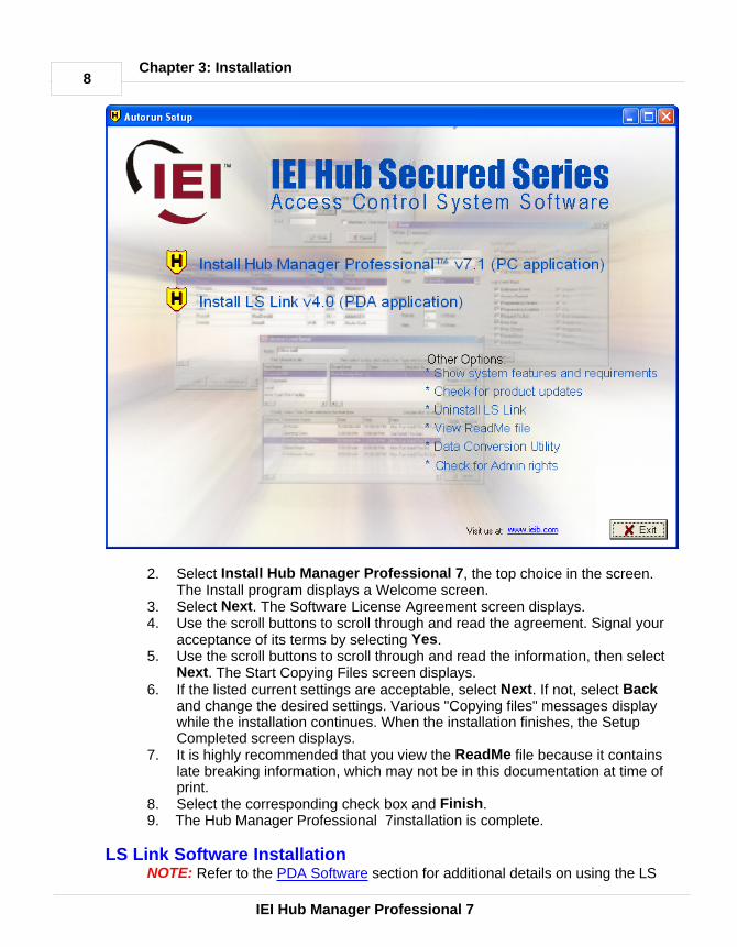
2. Select Install Hub Manager Professional 7, the top choice in the screen.The Install program displays a Welcome screen.
3. Select Next. The Software License Agreement screen displays.4. Use the scroll buttons to scroll through and read the agreement. Signal your
acceptance of its terms by selecting Yes. 5. Use the scroll buttons to scroll through and read the information, then select
Next. The Start Copying Files screen displays.6. If the listed current settings are acceptable, select Next. If not, select Back
and change the desired settings. Various "Copying files" messages displaywhile the installation continues. When the installation finishes, the SetupCompleted screen displays.
7. It is highly recommended that you view the ReadMe file because it containslate breaking information, which may not be in this documentation at time ofprint.
8. Select the corresponding check box and Finish.9. The Hub Manager Professional 7installation is complete.
LS Link Software InstallationNOTE: Refer to the PDA Software section for additional details on using the LS

9
IEI Hub Manager Professional 7
Chapter 3: Installation
Link PDA software.
IMPORTANT NOTE FOR CURRENT LS Link PDA SOFTWARE USERS: If youare currently using a version of the LS Link PDA software that was distributedwith a version of software prior to Hub Manager Professional 7, then youmust install the latest LS Link version that ships with Hub ManagerProfessional 7. Use of the previous version of PDA software will result inincorrect operation. The version of PDA software you must have to operatewith Hub Manager Professional 7 must be version 4 or greater. To check yourversion of PDA software, go to the main screen of the LS Link PDA software,and tap the titlebar where it says LS Link. A Help menu then appear. Nowselect About to display the version number. If this number is less than 4, thenyou must perform the installation from the Hub Manager Professional 7 CD.
1. Select Install LS Link (on the Hub Manager Professionalinstall CD)2. The install program displays a Confirmation Screen. This message is
displayed to remind the user that Palm Desktop and HotSync Managersoftware must be installed prior to installing LS Link software. If either ofthese applications are running, then the installation will ask if you want it toturn them off for you. The install will not continue until both applications areclosed.
3. Select OK. 4. Select the individual PDA's you want the LS Link program installed onto, or
you can select the 'All' checkbox to place the application onto all of thecurrent PDA's. Select Done to continue.
5. Following the steps in this screen will result in the LS Link software beingloaded onto the PDA the next time you perform a HotSync with the PDA.

10
IEI Hub Manager Professional 7
Chapter 3: Installation
6. Now perform a HotSync with each of the PDA's that you decided to installthe PDA software to. You will then see the LS Link program icon in theapplications screen of those PDA (see figure below).
11
IEI Hub Manager Professional 7
Chapter 4: Overview
Chapter 4: Overview
4.1 General Overview
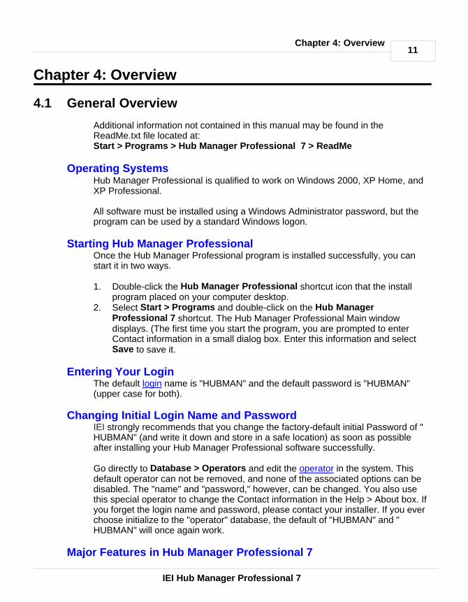
Additional information not contained in this manual may be found in theReadMe.txt file located at: Start > Programs > Hub Manager Professional 7 > ReadMe
Operating SystemsHub Manager Professional is qualified to work on Windows 2000, XP Home, andXP Professional.
All software must be installed using a Windows Administrator password, but theprogram can be used by a standard Windows logon.
Starting Hub Manager Professional Once the Hub Manager Professional program is installed successfully, you canstart it in two ways.
1. Double-click the Hub Manager Professional shortcut icon that the installprogram placed on your computer desktop.
2. Select Start > Programs and double-click on the Hub ManagerProfessional 7 shortcut. The Hub Manager Professional Main windowdisplays. (The first time you start the program, you are prompted to enterContact information in a small dialog box. Enter this information and select Save to save it.
Entering Your LoginThe default login name is "HUBMAN" and the default password is "HUBMAN"(upper case for both).
Changing Initial Login Name and Password IEI strongly recommends that you change the factory-default initial Password of "HUBMAN" (and write it down and store in a safe location) as soon as possibleafter installing your Hub Manager Professional software successfully.
Go directly to Database > Operators and edit the operator in the system. Thisdefault operator can not be removed, and none of the associated options can bedisabled. The "name" and "password," however, can be changed. You also usethis special operator to change the Contact information in the Help > About box. Ifyou forget the login name and password, please contact your installer. If you everchoose initialize to the "operator" database, the default of "HUBMAN" and "HUBMAN" will once again work.
Major Features in Hub Manager Professional 7

12
IEI Hub Manager Professional 7
Chapter 4: Overview
Password SecurityThis feature requires password entry before allowing an operator access to HubManager Professional software functions. A 2-part login is used. This passwordshould be changed after initial installation, periodically thereafter, and wheneverthe list of personnel who use the software changes. The factory default login is name: HUBMAN password : HUBMAN. (Names and Passwords are casesensitive)
Main ScreenThis dialog box provides organized access to the setup information used toconfigure your Access Control System. "Power" software users can employ thetoolbar buttons for fast access to all functions, without having to use menucommands for navigation. New and occasional software users can access thesame functions via the Hub Manager Professional menu system, eliminating theneed to rely on the user's memory for the location of each function in the software.
User List
The Hub Manager Professional user list provides a convenient means ofspecifying the access credentials of users in the system. An available wizard letsyou import names from a CSV (comma separated value) file when creating users.A CSV file is a simple text file that separates the fields with commas.
Transaction LogsThe Hub Manager Professional software can be used to retrieve the transactionlogs from controllers, save the transactions into the database, and view and printthe reports based on the data. Transaction Logs can be exported in acomma-delimited format, which is the default format for data import used byMicrosoft Excel.
Operator LogonUnlimited operators can be created; each operator can be assigned permissionsto any combination of screens; each operator can be assigned "Read" or "Write"access to certain areas. Name and password are case sensitive. Operators canbe established without a password by not enabling the password for that operator.
Time ZonesAn unlimited number of Time Zones can be created; each controller can chooseup to 8 time zones from that list. Each Time Zone must be named uniquely.
Auto Unlock Time ZonesOf the 8 Time Zones that can be assigned to most controller types, each one canbe designated as an Auto Unlock, which works as an auto unlock for that doorcontroller only, as long as that particular door controller has the Auto Unlocksystem option available and that option is enabled.
SitesUp to 1,000 Sites can be created using Hub Manager Professional. Each site canconsist of any device type and connection type These sites share users from the

13
IEI Hub Manager Professional 7
Chapter 4: Overview
same list of 20,000 users. There is a limit of how many doors can be included ineach site type, but that number is based on the controller type. If you have moredoors than is allowed in a site, then you must create another site and add theoverflow to that second site.
Maximum Doors Allowed Per Site
HC500 64
Hub+\Max 64
MaxII v1 64
MaxII v2 64
LS2\P 300
prox.pad plus 32
Door Time ZonesOnly Time Zone names are shown on the screen when a certain door is selectedin the Access Levels screen. You can select on any of the Time Zones to see thedetail of that Time Zone.
Door Controller Type SelectionEnables features supported for that door controller type.
Access LevelsVirtually unlimited access levels can be created. Each must be named uniquely(example, "Manager") and can be assigned access to any combination of doorswith in that "Customer's" system. Access levels also maintain some settings that auser has when trying to access those doors selected in that access level, such as"User Type" (standard, toggle, log dump, or relock). Access level also specifiesthe "Time Zones" applied to a user. The time zones can be different for eachdoor.
Users20,000 users total. A subset of users from the list of 20,000 users can be stored ineach of the controllers in the system based upon the user capacity of the doorcontroller type. Users are not added to doors directly, but are assigned to anAccess Level that has doors assigned to it.
An available wizard lets you import names from a CSV file when creating users.
Users Not Assigned to Doors DirectlyOnly the name, access level, and access credentials are set up on the userscreen. Users are not directly assigned to door controllers, but instead areassigned to an Access Level. The access level has doors, user types, card/codetypes, and time zones assigned to it. Making changes to the access settings for allusers that are part of the same access level, is quick and easy. Plus, adding auser to be part of a pre-existing access level only requires the new user's nameand credentials to be defined.

14
IEI Hub Manager Professional 7
Chapter 4: Overview
Add User GroupYou can add a group of users with common settings such as access level,sequential card numbers, and random generation of code.
Holidays 16 single date holidays per system. Single date Holidays are sent to all doors(controllers) in all sites.
16 block holidays per system. Block holidays are sent to all controllers in thesystem, which support block holidays. LS2\P controllers support Block Holidays.
'Connect To' SitesEach individual site must be 'connected to' before performing either a NetworkQuery or an Import Door Settings. It is not necessary when performing any of theoptions in the 'Import\Export Doors' screen. Connecting to a site is the software'sprocess of deciding which method is used when communicating with a particularcontroller type, and then performing all communications initializations for thatcommunication method. Once 'connected to' a site, you can choose to export toall doors in that site or any combination of the doors in that site.
Exporting to DoorsAn operator can export all settings or just the changes made to a site to a singledoor or any combination of doors. The software tracks the doors to which changesare made. Exporting just the changes to a door is less time consuming if onlyminimal changes were made, such as adding a new user. The initial export to adoor takes the most time because all of the data is new.
When exporting with Hub Manager Professional software for the first time, IEIrecommends that you uncheck the "export changes only" option. Thisrecommendation applies to existing devices as well as new devices. This ensuresthat all the data in this controller is over written with data that has been created by Hub Manager Professional.
Importing of Door DataAllows you to print the imported hardware settings and re-enter the data manuallyinto the program. This feature may not be available with controllers that aremanaged via PDA software. Access Level relationships are not stored in thecontrollers. In the case of a hard drive crash, all access levels are lost and cannotbe imported from the hardware, making a rebuild of the system is extremelydifficult if not impossible for complex system setups. Restoring from the databasebackup that was stored on removable media is the best way to recover from asystem crash, because all data including the Access Levels are also restored.
Export Time/DateAllows you to set the time/date in the controllers. You cannot export the time ordate directly to a PDA connected controller from the PC software. For PDAconnected controllers the PDA software has the ability to send the time to the

15
IEI Hub Manager Professional 7
Chapter 4: Overview
controller using the time and date of the PDA itself.
For directly connected controllers (if available), the PC's clock is used. Beforeperforming this function, verify that the Time and Date on the PC are correct.
Importing Transaction LogsYou can choose any combination of the doors within a site to import thetransaction log from and then press Start to start the import process. All newtransaction log data is appended to the existing transaction log data.
Scheduled-Import of Transaction LogsYou can specify the time that an Automatic Log Import is to occur. You can alsoset the delay (in days) between Auto-Imports. Auto-Import attempts to import fromeach door in each site. It will attempt to connect to each of the other sitesautomatically, dependant upon the connection type of that site. It attempts animport in this fashion for each site in that system. All new transaction log data isappended to the existing data.
NOTE: You must log out, but not exit, for 'Scheduled Log Import' to work properly.If an operator is logged in to Hub Manager Professional, the log retrieve will notstart automatically.
Opening Saved Transaction Logs or Reports for ViewingThe Operator can open the current transaction log file (containing the loginformation for all doors that were imported from) for viewing as well as openingarchived transaction logs. If a log is saved to an archive file, it can be opened in aprogram such as Microsoft Excel. Most reports are stored in comma-delimitedformat, but some are stored in space delimited format.
Archiving Transaction LogsThe current Transaction Log, which can consist of data from any combination ofdoors, can be moved into an Archive file if you no longer wish to use it in the newreports of Hub Manager Professional. If you perform Archiving, the TransactionLog data is now available in this Archive file. The Archive file is in CSV format,which means that you can easily open it in a CSV viewer such as Microsoft Excel.
Open an Archived Transaction LogThis option lets you load an archived transaction log file into the currenttransaction log file for viewing.
Network QueryNetwork Query reports Online\Offline, and Controller Type. Pictograms are usedto display this information. This feature will only query the site that you arecurrently connected to via the Sites directory, and it attempts to query all thepossible doors that could be at that site, one door at a time.
If you are performing a network Query on an PDA connected site, then theNetwork Query cannot speak directly to the controller. In this case the Time and

16
IEI Hub Manager Professional 7
Chapter 4: Overview
Date of the last imported Log Event will be displayed, which is useful if you wouldlike to know the last time this device was communicated with using the PDAsoftware.
Operator Audit TrailThe software maintains a time/date-stamped trail of which operator logged in, abrief description of the screens that operator accessed, and a brief description ofwhat was done in each screen. Exact details telling exactly what was changed arenot given. (Example: operator John Smith logged in; Door 1 was added ormodified). No filtering of the audit trail is possible to produce a customized reportwithin Hub Manager Professional, but it can be printed to a file and opened inanother program such as Microsoft Excel or Crystal Reports.
Operator Audit Trail ArchivingProvides the ability to move the operator audit trail to an archive database.
Database InitializationWARNING: Performing this operation will result in a loss of data. Pleaseperform a backup first. All existing data will be lost.The operator can select to initialize the database, just the Transaction Log, or justthe Operator Audit Trail. Initializing removes all data that was entered or stored ina particular database. This is a quick way to clear all data from a certain databasetype. It does bring the selected databases back to a default state.
Database BackupAllows you to create a backup of the existing databases. These backup files canthen be copied to a removable media. If the computer's hard drive crashes, youcould reinstall Hub Manager Professional and then copy the backup files back tothe Backup folder and then Restore these files.
Database RestoreAllows you to restore Hub Manager Professional data from the backup files storedin the backup folder. This would allow you to recover from a hard drive crash or togo back to the settings stored in the backup folder. If a backup was placed ontoremovable media, you must first copy the files back into the backup folder andthen perform the database restore routine.
Database Conversion\Migration (if available)A utility may be available that allows you to migrate your data from a previousversion of Hub Manager Professional or another access control program into HubManager Professional 7. This utility (if it exists, named "Conversion.exe," may belocated in C:\Program Files\IEI\HubManagerPro7\Program
Transaction Log Report FilterAllows you to customize the transaction log report to show only those items thatmeet the filter criteria, such as a date range, a specific user, a specific accesslevel, any combination of doors, or any combination of events.

17
IEI Hub Manager Professional 7
Chapter 4: Overview
Time Management ReportThis report tallies the total time in the building for each user per day as well assubtracting break time from the total time and gives that number also. This reportrequires controllers that can produce both "User IN" and "User OUT" events. If thecontrollers in the system do not have both User IN and User OUT events, thisreport can not calculate the amount of time a user was "IN" the building. See TimeManagement for more details.
Misc. Log ReportsThree types of canned reports are available. The first report type lets you see thevery first and very last events on a particular day for each door controller. Thesecond report type allows you to see a list of the different days that a particularuser had used the access control system. And the last report type shows all theusers that used the access control system on a particular day.
Assignment ReportsA collection of reports that allow you to see which items are assigned to otheritems. Such as: "Show me all the Doors that are assigned to the selected AccessLevel"
Database Report This report shows all programmed items within a certain database.
Help File Help file is included, you are now reading it, either electronically or in hardcopyformat.
Electronic Version: pressing F1 on any form will bring up a help topic relevant tothe form you are currently viewing.
Printing to Monitor (screen), Printer, or FileEvery place that printing is available, a standard screen prompts the user where toprint the data: monitor , printer, or to a space delimited file. This is a default formatfor importing text files into Microsoft Excel.
NOTE: To use this feature, a printer driver must be installed. If you are not using aprinter for your personal computer and have no printer drivers installed, add anASCII printer driver from your Windows CD-ROM, you can typically use theGeneric / Text Only printer driver installed on most PC's.

18
IEI Hub Manager Professional 7
Chapter 4: Overview
Default Time Zones One Time Zone 12:00 AM-11:59 PM, including all days of the week and holidays.This can be used for 24-hour users, that you want to give 24 / 7 / 365 access to.
Default UsersMaster Code with a code of 1234, and a Supervisor User with no code defined.For a complete listing of all user types and the devices that support the differentuser types, see the Access Levels topic.
Default Holidays No default holidays are defined.
Default OperatorOne default operator is set up (which is case sensitive, all upper case for both)with the name "HUBMAN" and password "HUBMAN" This operator can not bedeleted nor can any option be disabled. This default operators name andpassword, however, can and should be changed soon after installing thissoftware, for security reasons.

19
IEI Hub Manager Professional 7
Chapter 4: Overview
4.2 Initial Set Up
Organizing for Hub Manager Professional Access ControlGetting ready for programming your access control system is a simple matter, asthe software employs the concept of "facility work groups-schedules" for accesscontrol. This section describes the concepts involved and provides relevantprocedures.
Facility Work GroupsTo create and control electronic access for each door in your facility, the HubManager Professional software uses facility work groups; examples include officeworkers, supervisors, or work shifts combined with their corresponding normalwork times, days, and the doors they can access normally. This latter idea isknown as "Access Levels." It minimizes required software programming to asimple action of transferring a mirror image of the existing facility's employee workgroups and schedules into the corresponding Hub Manager Professional softwarescreens. Access is granted by issuing each person access credentials such as acard, RF Fob, Personal Identification Number (PIN), or other form of credential,and then assigning that person to an identified facility work group called AccessLevel (an Access Level is a combination of each person's work group, doors,times, and days), and then downloading this access level data to the controllers.
Creating Access Levels1. Create Access Levels by first identifying and grouping employees according
to the following parameters: · logical work groups such as office, factory, supervisors, and marketing for
the employees assigned to each work group· the normal group work schedule for each work group · the doors that each work group can access · the times that each work group can access the specified doors
2. Once you finish identifying and grouping employees, transfer this access levelinformation into the corresponding software screens ("forms") used toprogram facility access control parameters into the Hub ManagerProfessional software.
3. When you finish transferring access level information into the softwarescreens, download each completed software screen ("form") into thesystem's controllers, to control specified door access with Readers andKeypads.
Database Programming Screens ("forms")The major Hub Manager Professional database programming screens (a.k.a.forms) include:
Sites If more than one location is involved, input and identify the additional sites in thisform

20
IEI Hub Manager Professional 7
Chapter 4: Overview
Time ZonesInput logical facility work group schedules by days and times
HolidaysDates when access can be denied to some and granted to others, based upon thesetup of the Time Zones
DoorsIdentify each controlled door by name and specify a few basic monitoringparameters here
Access LevelsCombines the doors and times into an assignable access control structure thatcan be assigned to each user
UsersAssign each employee or visitor an access credential combined with an AccessLevel that can control employee or visitor access by door, time, day of week andeven holiday automatically
Preparing for Access Control ProgrammingUse normal employee work times to create logical automated access control bygroup and doors as follows:1. For each site in your facility, identify and list all doors to be controlled by
name and location.2. Example: Lobby, Computer Room, Accounting, Manufacturing, etc.3. List the groups of people who work at or regularly visit the facility, their normal
work schedules, and the doors they can access.
Examples:
General Office Workers8 AM through 6 PM. M-FLobby, Employee Entrance, Computer RoomNames: (List them here)(first and last names)General Supervisors24 hours a day, 7 days and holidaysAll doorsNames:(List them here)(first and last names)Marketing 7 AM through 7 PM M-FAll but AccountingNames: (List them here)(first and last names)Tech Support7 AM through 7 PM, M-FLobbyNames: (List them here)(first and last names).

21
IEI Hub Manager Professional 7
Chapter 4: Overview
4. Transfer the information into the Hub Manager Professional software asdescribed in the Transferring Work Schedule section.
5. Download the access control information to the controllers as described inthe export to doors section.
Preparing Work ScheduleTo transfer your current facility's work schedule into the Hub ManagerProfessional software, follow subsections below.
Preparing SitesIf your system controls more than one site, use the Sites screen in the HubManager Professional software to identify each site, identify its controllers, andestablish the necessary information for communications. Programming, reporting,and communication routes with each site are then linked automatically into the Hub Manager Professional software.
Preparing Time ZonesIn the Hub Manager Professional Time Zone programming screen, transfer thetimes that reflect the various schedules identified in the previous section.Example: For Time Zone, fill in each line to reflect each separate possibility oftimes, days, and holidays applicable to your employee work schedules.
General Office Workers: 8 AM through 6 PM. M-FGeneral Supervisors: 24 hours a day, 7 days and holidaysMarketing: 7 AM through 7 PM M-F
Tech Support: 7 AM through 7 PM, M-F
Preparing DoorsIn the Hub Manager Professional Door programming screen, transfer each door'sidentification into the system, by entering the door name and Time zones that areactive for the door. In this screen, enter the activities to be monitored andreported, such as electric lock timer for ADA, auto unlock-relock, forced door, anddoor ajar (propped door) events.
Preparing Access LevelsAs noted earlier, the Access Level concept allows a single-phase entry method forassigning employees and visitors to the appropriate door and time access control. 1. Using the Hub Manager Professional Access Levels programming screen,
transfer the identified work groups from your list.2. Assign logical titles for each group's access level by their type of employee
work group.3. Select appropriate time zones and doors.
Example:Marketing: 7 AM through 7 PM M-FAll doors but Accounting
4. Create an Access Level titled "Marketing," and then select the appropriate

22
IEI Hub Manager Professional 7
Chapter 4: Overview
time zone number(s) and doors that reflect the Marketing" group.
Preparing UsersUsing the Hub Manager Professional User screen, fill in the names, accesscredentials and select the Access Level (for example, marketing, supervisor). Thissingle step directs the software to create each employee's access privilegesautomatically.
Managing and Programming System AlarmsDoor Contacts can be monitored, and door ajar (propped door), forced doorevents annunciated for response. 1. Define how long each door can remain open before the door open event is
annunciated.2. Transfer the identified times for each door's information to the Doors screen
in the Hub Manager Professional software. 3. To annunciate a held open or a forced door event, first define the action to be
taken. Examples include "report the event" or "close a relay"; then add thisdesired action to the door information.
Providing for a Secure SystemThis procedure involves defining operators and the respective privileges for each.1. Define which operators are allowed to program the Hub Manager
Professional system and exactly which programming actions each ispermitted.
2. Using the Operator screen, specify all tasks/parameters that each operator isallowed to control, change, report on, or save. Each operator has his/her ownpassword for logon and then can access only their assigned tasks.
4.3 Menu System
Describing the Menu SystemThe menu system of the software includes the following commands:
SYSTEMSystem ManagerLoginLogoutChange PasswordExit
DATABASEOperatorsSitesTime ZonesDoorsAccess LevelsUsers

23
IEI Hub Manager Professional 7
Chapter 4: Overview
Holidays
COMMUNICATIONSImport Door SettingsImport\Export DoorsNetwork Query
TOOLSLog ArchivingAudit ArchivingDatabase Backup/RestoreDatabase Conversion UtilityRun Com Port TestExternal ToolsScheduled Log ImportTable InitializationIndexingApplication InitializationOptions
REPORTSLog FilterTime ManagementMisc Log ReportsAssignment ReportsDatabaseAuditArchive ViewerGenerate Data for External Report WriterScheduled Log Import Errors
HELPHelp (you're reading it right now)Check for UpdatesCheck for Custom UpdatesAbout
System Main Menu CommandsThe System main menu commands provide access to functions that are used forsystem configuration or maintenance.
SystemProvides a means of: - launching the System Manager feature which allows you to create, delete, and
switch between other Hub Manager Professional databases you have created- "logging into" the program- "logging out of" the program

24
IEI Hub Manager Professional 7
Chapter 4: Overview
- modifying current login password for the currently logged in operator- exiting the program
DatabaseContains options necessary for setting required system parameters to operate thedoor controllers, according to rules established for secure access to protectedareas.
CommunicationsAllows you to import the transaction log, which documents user activity fromindividual door controllers to the personal computer database.
ToolsPermit you to maintain the program's databases, back up the databases, ensureproper communications with door controllers, as well as gain access to otherutilities.
ReportsSupplies tools for processing and extracting of data from the program'sdatabases, such as summary forms, user lists, user activity lists, forms, etc.
Help Supplies access to online help information.
Selecting the System Menu ItemThe System option contains menu choices that allow you to log into the system,log out of the system, change your password, and exit from the program. SelectSystem from the main menu. The System drop-down menu displays.
4.4 Running the software
Once the Hub Manager Professional program is installed successfully, you canstart it in two ways.
1. Double-click the Hub Manager Professional 7 shortcut icon that the installprogram placed on your computer desktop or on the shortcut on the StartMenu.
2. Select Start > Programs and double-click on the Hub Manager Professional7 shortcut. The Main window displays, with the Login form.
NOTE: The first time you start the program, you are prompted to enter supportcontact information in a small dialog box. Enter the contact information and select Save to save it. This information can be changed by going to Help > About whilethe administrator operator is logged in.
Entering Your Login The default login name is "HUBMAN" and the default password is "HUBMAN".

25
IEI Hub Manager Professional 7
Chapter 4: Overview
Both are case sensitive.
Navigating through the ProgramThe following steps depict the path of a "typical" user through the software. Yoursituation may differ somewhat, dependant upon the door controller type andcommunication type you are using.
1. Install the door controller hardware successfully and program the controlleraddress into each door controller (if required by that particular controller type);next, make all the necessary "controller-to-PC" wiring connections (see thehardware manual for programming/installation details).
2. Change the default Login (Name and Password) as soon as possible afterinstalling the Hub Manager Professional software.
3. Go to the Overview section and read this material to learn the basic conceptsbehind setting up Sites, Time Zones, Holidays, Doors, Access Levels, andUsers.
4. Run the Hub Manager Professional program.5. Create all of your Sites using Database > Sites > Add button.6. Create the Time Zones needed for your system requirements.7. Create Holidays as applicable.8. Create Doors and assign the Time-Zones needed in each door controller, and
modify any of the default controller options as needed.9. Diagnose the customer's system by identifying the common groups of users
that have identical access privileges (Access Levels). Identify the differentpossible groups such as managers having 24 hour access to all doors in allsites, a cleaning crew that only has access on the front doors at certain timesof the day and week, 1st, 2nd, and 3rd shift workers that only have accessduring their respective shift periods, normal Monday through Friday 9-5 AMemployees, etc.
10. Go to Access Levels and create the Access Group privileges for that AccessLevel based on the diagnosis.
11. Go to Users and create the names and define that users access credentialfields.12.
12. Choose Communications > Import\Export Doors to export data to eachdoor controller in the system. If you have directly connected controllers in yoursystem, the Time and Date will also be updated during this process,assuming you have left the 'Update Time\Date' checkbox enabled.
13. If you are managing PDA connected controllers, when you are finishedexporting to all doors in all sites, you will need to cradle your PDA and runHotSync in order to send the data from the PC to the PDA. Once this step iscomplete, you will then visit each door controller with the PDA running the LSLink software. Refer to the PDA Software section for the details onsending\receiving data via LS Link. You should then return to the PC with thePDA and perform a final HotSync which will let the PC host program knowthat the data made it to the PDA managed controllers successfully.

26
IEI Hub Manager Professional 7
Chapter 4: Overview
4.5 System Setup Tasklist
OverviewThe System Setup Tasklist is displayed to help guide you through the stepsneeded to completely and thoroughly set up a new system.
If you are managing multiple Systems using System Manager, then each newSystem you create will have a fresh Tasklist, since all of these Tasks are relatedto each individual System.
Clicking on any of the blue links will bring you to the specific screen that performsthat action. For example: if you click on the Create Sites link, then the Sitesdirectory will be opened, where you can then select the Add button to create a newSite.
Once a task is completed, that task will be crossed off the list, the link to that taskwill no longer be active, and a checkmark will appear next to it showing you thatthe Task is completed.

27
IEI Hub Manager Professional 7
Chapter 4: Overview
Inactive links will become active again, if the action that removed that link is nolonger true. For example: if you delete a Site and there are no longer any Sites leftin the System then the Create Sites link will once again become active.
There are some Tasks that do not require that you actually Add an item, but it isrequired that you at least visit that screen in order to have that Task seen ascompleted. The Tasks that you are required to at least visit are: Create TimeZones, Create Holidays, and Create Operators. The other Task that is not actuallymonitored for success is Export Data to Controllers. Just the act of opening theExport screen is enough to complete this particular Task.
It is recommended that the Tasks be performed starting with the first Task andending with the last Task. Several Tasks require that other Tasks be completedfirst. In these cases, you will be brought to the Task that is required. For example:if the very first Task you select is Create Doors, you will receive a messagesaying that you must create a Site before you can add a door, and you will then bebrought to the Sites directory where you should then add a Site.
Once all of the items in the System Setup Tasklist are complete, the list will beremoved from sight. Once the Tasklist is removed, certain action you perform maybring make the Tasklist visible again. These actions include: · performing a Database Restore from a dataset that does not have all of the

28
IEI Hub Manager Professional 7
Chapter 4: Overview
required Tasks completed (Tools > Database Restore)· performing a Tools > Database Initialization
· enabling the option that says to display the Tasklist even if all tasks arecompleted
4.6 PDA Software
LS Link PDA SWLS Link is IEI's PDA software designed for communication between Hub ManagerProfessional and LS2\P controllers. IEI's LS2\P controllers are standalone fullyintegrated electronic access control door locks that communicate via infrared to aPalm OS PDA. These controllers have two way infrared communicationscapability. By employing a PDA and the LS Link PDA software, IEI's controllerscan be part of an overall access control system all managed by Hub ManagerProfessional.
NOTE: Refer to the section titled Installation for details on installing the LS LinkPDA software.
LS Link System RequirementsThe following are a list of required equipment in order to use LS Link PDAsoftware· IEI's Hub Manager Professional 7 software· PDA with Palm OS 3.5, 4.x, or 5.x· HotSync software (provided by PDA vendor)· 250KB of available memory on the PDA for each controller you are managing.· See the ReadMe file for the most recent list of known compatible PDA models.
the ReadMe is located in Start > Programs > Hub Manager Professional7 >ReadMe
PDA Data TransfersThe PDA acts as the "connection" between Hub Manager Professional and thedoor controllers. Data transfers in either direction must occur in a series ofoperations, involving the intermediate HotSync step.
Exporting From Hub Manager Professional to the PDAWhen exporting to a PDA connected site, Hub Manager Professional creates datafiles that will be transferred to the PDA the next time a HotSync Manager sessionis executed. Refer to the Export to Doors section for details on exporting data.
1. Choose Communications > Export to Doors, and enable the ExportChanges Only option, then select the Start button and wait for thecommunications to finish.
2. Set the PDA in its cradle and initiate HotSync with the PDA.3. Take the PDA to the controllers and export to each door using the Imp/Exp
button in LS Link, and follow the prompts

29
IEI Hub Manager Professional 7
Chapter 4: Overview
4. Go back to the PC and set the PDA in its cradle and initiate a HotSync withthe PDA. Log data is now on the hard drive awaiting import into Hub ManagerProfessional.
5. Choose Communications > Import\Export Doors, and enable the ImportTransaction Log option, then select the Start button and wait for thecommunications to finish.
6. All data between Hub Manager Professional and the controller is fullysynchronized.
LS Link automatically handles all existing door data during the HotSync Managerprocess. All door export data from the Hub Manager Professional stored on thePDA prior to the start of the HotSync Manager session is deleted from the PDAmemory. All log event data from the doors stored on the PDA prior to the start ofthe HotSync Manager session is transferred to the PC for import by Hub ManagerProfessional. Once the HotSync Manager has completed run LS Link from thePDA Application Screen. LS Link's main screen has three buttons and a Site dropdown list.
The title bar information symbol (in the upper right) is functional in all LS Linkscreens. Selecting the information symbol will provide you with definitions anddescriptions of the features/functions and data presented in the current screen.
Imp/Exp Button

30
IEI Hub Manager Professional 7
Chapter 4: Overview
Initiates communication services. Communication services are: door identification,download of event data from a controller, and upload of new configuration data toa controller.
Files Button
· Displays the door management screen and provides access to advancedfunctionality.
· Any door controller with a checkmark in the C column denotes thatconfiguration data is stored on the PDA that has not been sent to the relativecontroller. This is useful to know what doors you still need to visit.
· Any door controller with a checkmark in the L column denotes that transactionlog data is on the PDA that has not been transferred to the PC via a HotSyncoperation.
Settings Button Displays settings for the LS Link program itself.
Site Drop Down List Contains an alphabetical list of the Sites that door data exists for in the PDA'smemory. The Site shown in the Main Screen is the currently active site. Alloperations within LS Link are performed on the currently active site. When LS Linkis launched, the Site Drop Down List will now contain a single entry for each site

31
IEI Hub Manager Professional 7
Chapter 4: Overview
for which doors were exported. The list is arranged alphabetically and initially, theactive site is the first on the list.
Setting Up Your PDA to Communicate with LS2\P Door ControllersWe can now select a site from the Site List in the Main Screen. If you only have asingle site, it will be automatically selected when LS Link is launched. After youhave selected a Site, select the Settings button. The Configuration Screen willappear. LS Link offers a number of program preferences that can be selected inthis screen. These items are global – meaning they influence the way LS Linkfunctions as a program independent of the currently active site.
The Configuration Screen has several settings: Auto Export Time/Date, AutoImport Log, Comm Method and Comm Speed.
Auto Export Time/Date When selected, LS Link will automatically update a device's stored time and datewhenever communication is established with a device. This option is turned on bydefault. It can be turned off if you know the Time of the PDA should not be sent tothe controller, in the case where you are crossing over a Time Zone boundary.
Auto Import Log When selected, LS Link will automatically retrieve the event log from the devicewithout prompting the user. When this option is not selected, LS Link will display a

32
IEI Hub Manager Professional 7
Chapter 4: Overview
message box letting the user know how many events the device contains andprompt them to choose to retrieve the log if they desire. This option is turned offby default.
Comm Method Because there are differences in the way the different models of the Palm PDAhardware access and use the infrared outputs of the PDA, there is a drop-downlist allowing selection of what 'IR Channel' (infrared) LS Link is going to use.
Here is a list of known compatible PDA's and the 'IR Channel' (infrared) settingthat should be set in the LS Link PDA application.
Make Model 'IR Channel' Setting (infrared)Aceeca Meazura 2Handspring Visor 2Kyocera 7135 Smart Phone 2Palm IIIc 1Palm IIIx 1Palm IIIxe 1Palm m105 2Palm m125 2Palm m130 2Palm m500 2Palm m505 2Palm m515 2Palm V 1Palm Vx 1Palm VIIx 1Palm Tungsten E 3Palm Tungsten E2 5Palm Tungsten T 3Palm TX 5Palm Tungsten T2 3Palm Tungsten W 2Palm Tungsten C 4Palm Zire 2Palm Zire 21 3Palm Zire 71 3Palm Zire 72 5Palm Zire 31 5Sony Clie SJ20 2
Models with known problems:Palm Tungsten T3
An updated list of known compatible PDA's may also be available at www.ieib.com

33
IEI Hub Manager Professional 7
Chapter 4: Overview
or in the ReadMe file located at:Start > Programs > Hub Manager Professional 7 > ReadMe
If your PDA is not in the known compatible PDA list then there is still a chance thatit may work, but there is no guarantee. You may also use the following PDAdescriptions to help you choose the best IR Channel setting:· IR Channel 1 (infrared) - Older PDA's, such as the Palm IIIxe require this
setting· IR Channel 2 (infrared) - This setting is used for PDA's running Palm OS 4.x or
5.x and the PDA does not have an OMAP logo on the back of the PDA· IR Channel 3 (infrared) - Select this setting for PDA's that display an 'OMAP'
logo on the back of the PDA, see the OMAP logo below.· IR Channel 4 (infrared) - See the list above for PDA models that use this setting· IR Channel 5 (infrared) - See the list above for PDA models that use this setting· Emulator - This setting should never be selected
Comm Speed Drop-down list allowing selection of the baud rate to communicate to the device. The default setting is 19200 and should not be changed.
Exporting and Importing Data Between the PDA and the Door· To find out which doors have new Configuration data to be delivered, select the
Files button on the Main Screen. The Door Management Screen will appear.

34
IEI Hub Manager Professional 7
Chapter 4: Overview
· The Door Management Screen displays a list of each of the door controllerswithin the selected site. The table is made up of 3 columns: 'Door Name', 'C L',and Action.
Door Name The text ID given by the user to the PC software to identify the particular device.
C / L Indicates what operations are pending for the door. A checkmark gets placed incolumn C when LS Link has new configuration data available to upload to thedevice. A checkmark gets placed in column L when LS Link has received newevent log data from the controller that has not yet been returned to the PC via aHotSync.
NOTE: Some doors on the PDA may not have new configuration data.
Action The Action list is a drop-down list of advanced functions that can be invoked to acton the door. These actions include checking the current Time/Date on thecontroller, or looking at the current configuration details. Some actions such asthe 'Remove' option should not be performed unless you are asked to do so by aTechnical Support representative.

35
IEI Hub Manager Professional 7
Chapter 4: Overview
Communicating with a Door1. Select the Imp/Exp button of the LS Link main screen and point the infrared
port of the PDA at the infrared port of the controller as shown in the followingdiagrams. See the installation manual for further details on the infrared ports ofthe controllers.
NOTE: The optimal distance between the PDA and the controller is approximately3" to 10". Some PDA's perform better at the shorter range and some performbetter at the longer range due to the variations in the infrared lens of the PDAhardware. Longer export and import times will result from putting the PDA eithertoo close or too far away from the infrared receiver of the controller. This extratime is due to retries that may result from communication errors.
2. The PDA application will now prompt you to "Please enter your communicationscode at the door". The process of unlocking communications is required inorder to communicate with the controller.
3. Enter a valid "Communications Unlock" user credential at the controller. SeeThe Access Levels section for more details on using 'Comm Unlock' codes.The Master Code can always be used to unlock communications (the factorydefault Master Code is 1-2-3-4-*).
4. If this is the first visit to this door, LS Linkprompts you to select the door fromthe list. When you visit this door again, LS Link will automatically recognize thatyou have communicated with this door before and will only prompt you toconfirm the door name as noted in the next step.

36
IEI Hub Manager Professional 7
Chapter 4: Overview
5. If you have communicated with this controller hardware before, or you justselected the door from the list in the step above, then LS Link will ask you toverify the door controller you are communicating with.

37
IEI Hub Manager Professional 7
Chapter 4: Overview
6. LS Link will then query the controller to find out how many events it has storedand prompt you with a choice to retrieve them or not. For demonstration, select'Yes'. LS Link now displays a status bar and retrieves the events from the door,and displays how many events were retrieved from this controller.

38
IEI Hub Manager Professional 7
Chapter 4: Overview
7. LS Link then determines whether the configuration data stored on the PDA is'newer' than that in the device. If the data is newer, you will be prompted with achoice to send the data to the device or not.
8. Upon selecting 'Yes', LS Link displays a status bar and transmits all new data tothe device.
NOTE: An export of 2000 users may take about 1.5 minutes. For securityreasons, a full export will occur if you have entered programming mode on thecontroller, or if you have changed the door or site name in Hub ManagerProfessional. Normally, only changes are sent, taking only a few seconds if only afew changes were made.
9. When finished, LS Link displays a Complete message (shown above).
4.7 Uninstall
Uninstalling Hub Manager ProfessionalWARNING: Uninstalling Hub Manager Professional will result in a loss of alldatabase data that you have created.
To uninstall Hub Manager Professional you can simply use the "Add or RemovePrograms" feature of Windows, and choose the application named Hub ManagerProfessional 7.

39
IEI Hub Manager Professional 7
Chapter 4: Overview
NOTE: Any files that you created while using Hub Manager Professional, such asreports, backups, or other files that were created by the program itself, will not beremoved from the hard drive. Those files will need to be removed manually. Onlyfiles that were placed onto the hard drive by the installation program will beremoved, including the entire database.
Uninstalling LS LinkThe LS Link software is uninstalled using the installation CD that came with theproduct. When the Autorun.exe program is run, you will see an option labeled"Uninstall LS Link". Simply select that option to remove the PDA associated filesfrom Palm Desktop.
NOTE: You will have to manually remove the LS LinkPDA application from thePDA itself. Please refer to the PDA's documentation for instructions on removingapplications from the PDA.

40
IEI Hub Manager Professional 7
Chapter 5: System
Chapter 5: System
5.1 System Menu
Standard program functions can be accessed via the System menu. System ManagerLoginLogoutChange Login PasswordExit
5.2 System Manager
System Manager allows Hub Manager Professional to manage any number ofindividual discrete system databases.
System Manager can also allow access to those Systems by additional PC's onyour network. The operators of those PC's must have sufficient network accessrights to the folders that store the System data.
A "system" consists of a database and files directly associated with that particular

41
IEI Hub Manager Professional 7
Chapter 5: System
database. Each System is data independent of the other "Systems" you havecreated.
When a system is created it is stored in a folder that you specify. That folder iscalled a "System Repository". System Repository folders can be created in anynetwork location which the creating PC has access to. Any number of SystemRepositories can be created, and a System Repository can store any number ofSystems.
Applications One operator manages one system
System Manager allows a single operator to manage a single System database.This is nothing new and was always the case in prior versions of Hub ManagerProfessional. But now the added advantage is that the system dataset can bestored remotely on a server in a folder that is included in automatic backups. Thatfolder is the "System Repository" folder.
NOTE: The act of backing up in this scenario is not performed by SystemManager or Hub Manager Professional, but would be performed by the backupprogram running on your server.
Application Example: A single person within a company is responsible formanaging the access control system in that company. Hub Manager Professionaland System Manager is installed on that persons PC. The System may be storedon that PC or somewhere else on the network.
One Operator Manages One System
One operator manages many systems

42
IEI Hub Manager Professional 7
Chapter 5: System
System Manager allows a single operator to manage multiple discrete systemdatabases, such as those of multiple independent customers. In this scenario, it islikely that all data is stored on the operators PC (or in a folder on a server that onlythat operator has access to) and this operator can communicate to the accesscontrol hardware via modem, network, or other communication type that applies tothe hardware. The operator can also visit the hardware and connect to itphysically.
Application Example: A dealer acts as a central station and manages thedatabases for several customers. He can either connect to the hardware viamodems, PDA's, or network connection, dependent upon which communicationtypes the access control hardware supports.
One Operator Manages Many Systems
Many operators manage one systemSystem Manager can be used to allow multiple operators on different computersto manage a single database that is stored on the network and is accessible by allof the operators that wish to manage the data. This is helpful if a company hasseveral people responsible for adding, deleting, and editing users within their owndepartment.
Application Example: A company with several departments manages it's ownsystem. Each department head is responsible for managing the users in their owndepartment. Hub Manager Professional and System Manager is installed on eachdepartment heads PC. The Network Administrator creates a new folder on aserver somewhere on the network and grants each department head access tothat new System Repository folder.

43
IEI Hub Manager Professional 7
Chapter 5: System
System Manager is then run on any of the PC's. The operator then selects "CreateNew System", at which point the operator will select to create the new system inthe new System Repository folder that the network administrator had created.
Each department head can then run System Manager and attempt to open thatSystem dataset stored in the System Repository. After all changes are made andexported to the controllers, the department head will then close the System, atwhich point the system dataset is sent back to the System Repository folder onthe network and is ready for access by another department head.
NOTE: If a department head in attempting to open a system that is already in useby another department head, access will be denied. A "Close System Request"can be issued at that point. Please see the section in this topic labeled "OpenSelected System (while that system is already opened on another PC)" for moredetails.
Many Operators Manage One System
Many operators manage many systemsSystem Manager was designed to be used to maintain multiple individualdatabases across a network, by multiple operators.
Application Example #1 - Central Station: You're a dealer who manages theaccess control systems for several of your "end user" customers, and you havemultiple employees at your central station who are allowed to modify the data ofthose customers.
Hub Manager Professional and System Manager is installed on each employee

44
IEI Hub Manager Professional 7
Chapter 5: System
PC that may be managing a customer system. System Manager is run on any ofthose PC's, and is used to create a new System for each customer. Thosesystems can be stored in a folder anywhere on the network, as long as that folderis accessible to the other employees that may also be managing that customer'ssystem. All systems can be stored in one System Repository folder or eachsystem can be stored in it's own System Repository folder, thereby allowing it tobe completely separate. This could be helpful if you do not want to give certainemployees access to a particular system. You could simply have the networkadministrator create a folder on the network that is inaccessible to a particularemployee, and then store that customers system in that folder.
Many Operators Manage Many Systems - Central Station Example
Application Example #2 - Multiple Bank Branches: A Corporate SecurityOfficer wants to be able to manage the access control for all branches of a bank,and also allow each Branch Manager to manage the data of their own branch. Allbank branches are on the corporate network.
The Corporate Security Officer would instruct the Network Administrator to createa separate System Repository folder on a server for each of the bank branches(as shown in Server #1 in the following diagram). The Network Administrator willalso set the network access privileges of each folder to only allow the CorporateSecurity Officer and the Branch Manager of that particular branch. SystemManager is then used to create a system in each of those System Repositoryfolders.

45
IEI Hub Manager Professional 7
Chapter 5: System
Many Operators Manage Many Systems - Multiple Bank Branches Example
TermsSystem Manager
System Manager is a program that is responsible for accessing the SystemRepository and loading System datasets onto the local PC. System Manager alsosends that same dataset back to the System Repository.
System Repository (aka Repository, or Repository folder)A 'System Repository' is a folder that can store any number of System Datasets.Any number of System Repository folders can be created based upon yoursecurity needs. All systems stored in that repository can be accessed by anyinstallation of System Manager that has network privileges to see that particularSystem Repository folder.
System Dataset (aka Dataset or System)A 'System Dataset' is a compressed zip file that stores all the data that is relatedto that particular System, currently including (but not limited to) the completecontents of the following folders: Archive, Backup, Database, Gateway, Maps,PDAFiles, Print, and ReportDB.
OperatorPerson who is using the Hub Manager Professional and System Manager

46
IEI Hub Manager Professional 7
Chapter 5: System
software.
Overview of System ManagerSecurity
System Manager does not restrict access to any of the System Repository foldersin any way. Access to the repository folders is based on the network privileges youwere given by the network administrator.
A System Repository may be located either on the local PC or in any folder on thenetwork. The security of the stored data is only as good as the security of folderthat stores the data. System Manager uses the security infrastructure of the PC asset up by the Network Administrator.
The software will use whatever means of network connectivity are provided by theclient PC. (This may be a shared folder, network folder, mapped folder, VPN,etc..).
Launching and Closing System ManagerSystem Manager can be seen running in the System Tray (typically in the lowerright corner of your screen, see below)
System Manager is automatically launched when Hub Manager Professional islaunched, but System Manager is not automatically closed when Hub ManagerProfessional is closed. This allows System Manager to be able to processmessages from other installations of System Manager running on other PC's. Onetype of request could be that the other PC needs to access to the dataset that isopen on your PC, and that other PC will perform a 'Request to Close'.
Basics of OperationWhen a System is opened, System Manager program will actually make a localcopy of the data for use during program operation and will store the data back tothe System Repository folder upon selecting to close the system. This copy is alsocreated even if the data repository folder is on the local PC.
Standard OptionsOpen Selected System (while the system is not opened on another PC)
This option is used to open the system that is selected in the list. If this option isselected and a different system is already open, then the open system will beclosed first, and then the selected system will be opened.

47
IEI Hub Manager Professional 7
Chapter 5: System
Open Selected System (while that system is already opened on another PC)
· If a system is already open when you select this option, then that system will beclosed prior to opening the new system.
· After selecting the "Open" option, System Manager must check to see that theselected system is not currently open on another PC running System Manager.If the system you selected to open is already open on another PC, a messagewill be displayed showing information relative to the PC that has the systemopen: the name of the computer, the name of the person logged in when thesystem was opened, and the time\date when the system was opened by thatoperator.
Upon selecting OK, you will then be asked if you want to send a "Close System"request to the PC that has that system open. Selecting OK, will start the "CloseSystem" process.
At this time the PC requesting the close will send a "Close Request" and willcontinuously waits for a "Close Successful" response from the PC that is closingthe system dataset.
NOTE: In order for the close request to be processed by the PC that has thesystem open, ALL of the following MUST be true:

48
IEI Hub Manager Professional 7
Chapter 5: System
- the other PC is powered up- the other PC is logged into Windows properly- the other PC has System Manager actively running. Hub Manager Professionaldoes not need to be running, just System Manager. If System Manager is notrunning, then run Hub Manager Professional (if it is not already running) andselect System > System Manager from the main menu of Hub ManagerProfessional.- the System Manager application running on the other PC must be in the typicalidle state, and not be in use by the operator, and must not have any messagesdisplayed that require a response from an operator.
Assuming all of the requirements are met, then the other PC will typically see theclose request. The "Close Request" will typically be processed by the other PCwithout any operator intervention required. During the automatic closing of thesystem on the other PC, any operator logged into Hub Manager Professional willbe logged out and the system dataset will be closed normally. If Hub ManagerProfessional was running at the time, then a message will be displayed alertingthe operator that the system was closed by another operator on another PC.
If any of the requirements are not met and the other PC does not respond with aclose successful within the predetermined amount of time (default is 30 seconds) ,then a message will be displayed alerting you that the "Close Request" was notprocessed.

49
IEI Hub Manager Professional 7
Chapter 5: System
At this point you have 2 options: · Select OK and wait another 30 seconds for the close successful response from
the other PC. You may want to do this if you knew you were having networkconnection problems, or you contacted the owner of the other PC and had thatoperator put the PC into the required state as noted above.
· Select Cancel, which will cancel any further waiting, but will then display anothermessage asking if you want to force an "emergency override".
An "emergency override" is NOT recommended and should only be used in rarecases. The reason an emergency override is not recommended is because anychanges made to the dataset while that dataset was open on the other PC will bediscarded when the other PC gets around to closing the dataset.
If an "emergency override" is executed, then the PC requesting the close simplyopens the copy of the system dataset that is stored in the System Repository.That copy of the dataset will not contain any of the modifications made by theother operator who had it open. After the dataset is opened on your PC, amessage will be displayed to the other operator that will inform the other operatorthat their data was overridden and that the dataset they currently have open will beabandoned when that system is eventually closed.
NOTE: In all cases, any changes made to a System dataset while it was open onthe other PC will need to be reentered if that System was overridden.
An "emergency override" is known to be helpful in the following situations:· The other PC, that had the system dataset you need, has crashed and the
data on the hard drive can't be recovered. The override will simply causeSystem Manager to abandon the dataset that was open by that operator, andallow you to open the last saved dataset.
· You need to make a critical change to the system such as deleting a disgruntledemployee and you need to delete that user and get the data exported to thecontrollers immediately.

50
IEI Hub Manager Professional 7
Chapter 5: System
Close Currently Open SystemThis option takes all of the data associated with the currently open system,compresses it into a single file and sends that "dataset" back to the SystemRepository from which that dataset was opened from.
Advanced OptionsCreate New System
Creating a system is the process of creating a new discrete dataset in a folder thatyou specify. The system name is typically the name of a company, or a subset ofa company. The folder that you specify may be either an existing SystemRepository folder or the operator may choose to specify a new folder that will beconsidered an additional System Repository folder.
NOTE: If a new system is created, and an existing System Repository folder isselected, then that new system will become available to other installations ofSystem Manager that already have access to the System Repository folder youcreated the new system in. Choosing to use the same System Repository folder tostore all systems may be helpful if every installation of System Manager on yournetwork is to have access to all systems that are created. If all installations ofSystem Manager are not going to have access to all the systems you create, thenit is recommended that you create a separate System Repository folder for eachsystem you create.
Locate / Import RepositoryThis is the process of using a particular installation of System Manager tonavigate to a "System Repository" folder that is currently not "known" by thisparticular PC. Once you have browsed to that folder, select OK. Now all Systemsstored in that System Repository folder will be displayed in your list of knownsystems.
NOTE: In order to properly access a System Repository folder your NetworkAdministrator must have given you full Read and Write privileges to that folder.

51
IEI Hub Manager Professional 7
Chapter 5: System
Rename Selected SystemThis option changes the name of the selected system. Once a system is renamed,the next time an operator runs System Manager the new system name will bedisplayed in the list of known systems.
A system should be closed before it is renamed.
Delete Selected SystemWARNING: This option will result in the permanent loss of the selectedsystem data. This option will completely remove all data associated with the selected system.
A system must be closed before it is deleted.

52
IEI Hub Manager Professional 7
Chapter 5: System
Clear List of Known SystemsThis option clears the list of known System Repository folders which are storedlocally on this particular PC. This will in turn remove all system names from the listof known systems. This is helpful if you have previously browsed to a SystemRepository that you no longer want to see the contents of, then this option willclear the entire list and start from scratch.
Refresh ListForces an update of the "Known Systems List". This option is rarely required.
Show Selected System InfoThis option will collect some information on the selected System and display thatinformation in the status messages below the system list. Status message are notdisplayed by default, but you can simply resize the status message section ofSystem Manager by dragging the resize splitter at the bottom of the KnownSystem list.

53
IEI Hub Manager Professional 7
Chapter 5: System
ExitSelecting Exit will not close the System Manager program, but will simply minimizethe program to the Windows System tray (typically in the lower right corner of thescreen). If you want to completely close System Manager then you must right clickon the System Manager program icon in the system tray (see below) and select'Exit System Manager'.
System Manager Related Options Selectable in Hub ManagerProfessional

54
IEI Hub Manager Professional 7
Chapter 5: System
Enable System Manager - multiple discrete databases can be createdWhen enabled, this option will enable the System Manager feature. If you are notusing any of the features of System Manager as described is this section, you candisable this option. Disabling this option will remove System Manager from theSystem menu of Hub Manager Professional and any opening and closing ofsystem datasets from a system repository folder will cease.
Disabling System Manager will cause Hub Manager Professional to handle adatabase as it has in previous versions of Hub Manager Professional, whereasonly one system exists and the system is always open.
NOTE: Disabling System Manager is recommended only if the following are true: - you have only one system - the dataset to reside on the local PC- the only operator that is going access the data is an operator of that particularPC
Auto open the most recently used system when the program startsNOTE: This option requires that the 'Enable System Manager' option above isenabled.
Enabling this option will cause System Manager to automatically open the Systemthat was most recently used, without the need to intentionally run SystemManager. The opening of that system will automatically occur when Hub ManagerProfessional is launched. Enabling this option is helpful if you are typically usingHub Manager Professional to edit the same System over and over again.
Enabling this option is helpful if you have installed Hub Manager Professional onand operators PC and you feel that operator would had no need to know about orreason to deal with System Manager. If this is your reason for enabling this optionthen you will also want to enable the 'Auto Close' option below.
Auto close any currently open system when this program closesNOTE: This option requires that the Enable System Manager option is enabled.
Enabling this option will cause System Manager to automatically close thecurrently open system when the Hub Manager Professional program is closed.This is useful if you have multiple operators that access a particular database,because it increases the chances that when an operator is done exportingchanges and closes Hub Manager Professional that the System Dataset will besent back to the System Repository and made available to other operators onother PC's running System Manager.
Automatically return control after a system is openNOTE: This option requires that the Enable System Manager option is enabled.
Enabling this option will cause System Manager to give control back to HubManager Professional directly after a system is loaded, without giving a 'System

55
IEI Hub Manager Professional 7
Chapter 5: System
opened successfully' message or requiring that you close System Manager. Onceyou have an understanding of how System Manager works, enabling this optioncan help speed up the System Open process a little.
5.3 Login
To obtain access to the Hub Manager Professional program's features, you mustenter the pre-designated login, which consists of two entries, Name andPassword,into the Login dialog box. [The factory-default Name is "HUBMAN" (allupper case letters); the default Password is also "HUBMAN" (all upper caseletters). IEI recommends that you change the default operator name andpassword immediately after initial installation.
NOTE: The login feature is case sensitive. If the Name portion is "HUBMAN"followed by a Password portion of "HUBMAN" for example, both must be typedexactly as shown: in all upper case.
1. Select System > Login from the main menu. The Login dialog box displays.
2. Enter your Name on the first line of the Login dialog box (for example, thefactory-default of "system"), press <Tab> to move to the second line, enteryour Password on the second line (for example, the factory-default of"startup"), and select OK (or press <Enter> on the keyboard). If you enter avalid 2-part login, the Hub Manager Professional program activates, givingyou access to program options (they are no longer grayed out). If the login isnot valid, an "Incorrect login entered" message appears.
3. If the "Incorrect login entered" message appears, check your login and thenre-enter it. After you log on to the system successfully, you can access thespecific data and functions assigned to your specific user name by thesystem administrator.

56
IEI Hub Manager Professional 7
Chapter 5: System
5.4 Logout
The Logout option permits an individual system user to "Logout" or quit the HubManager Professional program without actually exiting the program. Wheneverthis option is chosen, to access the program's features once more, a new operatormust log into the system again.
Select System > Logout from the main menu. For example, a reason to Logoutand not exit the program is if you enable "Schedule Log Import" under the Toolsmenu; you must log out but not exit the program completely before the automaticimporting of transaction logs can occur.
In a PDA connected system, when a HotSync is performed, transaction logs areretrieved from the PDA and placed onto the PC, but are not sent to the HubManager Professional database. By using the scheduled Log Import feature, youcan have those transaction log events imported into the database on a schedule.This is helpful if you want to have someone responsible for using the PDA toretrieve transaction logs from the door controllers, but not give them access tothe Hub Manager Professional program itself. Now that person can simply visiteach door controller and then HotSync the PDA afterwards, the log import to thedatabase will then be performed automatically.
5.5 Change Login Password
This option lets you change the Password portion of your system login. IEIstrongly recommends that you edit the default operator using Database >Operators as soon as possible after installing your Hub Manager Professionalsoftware successfully. Make sure to write down the name and password andstore them in a safe location.
1. Select System > Change Password from the main menu. The ChangePassword dialog box displays.
2. Enter the current password on the first line, the new password on the secondline, re-enter the new password on the "Verification" line for confirmation, andthen press Save.
3. If you have changed the initial Password and do not remember your currentPassword, contact IEI technical support.
5.6 Exit
The Exit option exits you from the Hub Manager Professional program. Onceselected, the Hub Manager Professional main window closes, and you mustrestart the program to access its features. Select System > Exit from the mainmenu.
Upon exiting, the program may prompt you that changes to some number of doorshave occurred but these changes have not been exported to those door

57
IEI Hub Manager Professional 7
Chapter 5: System
controllers yet.
In addition, a prompt may display stating that Scheduled Importing of transactionlogs is enabled. Scheduled Importing can not occur if you exit. For the automaticimport to work properly, you must log out of but not exit Hub Manager Professional.

58
IEI Hub Manager Professional 7
Chapter 6: Database
Chapter 6: Database
6.1 Database Menu
All data types can be accessed via the Database menu system. OperatorsSitesTime ZonesDoorsAccess Levels UsersHolidays
6.2 Operators
Operators OptionThe Operators option lets you assign to unlimited operators the ability to create,view, and manipulate data in the Hub Manager Professional databases. Detailedscreens allow you to specify which activities a particular operator can perform. Alloperators having any type of access to Hub Manager Professional databases arelisted. To select the Operators option, select Database > Operators. TheOperators screen displays. The information on this screen is almost the same asdescribed in Table 4-1. (Instead of remote site information being listed, operatorsinformation is shown.) An operator is a combination of NAME and PASSWORDthat is used to login to Hub Manager Professional.
Adding an Operator1. Select the Add button on the Operators screen.

59
IEI Hub Manager Professional 7
Chapter 6: Database
2. Enter the information in the operator detail fields as required.3. Select Save to save the operator data to the operator database.
Field/Button DescriptionName
Specifies the name of the operator.Password
Specifies the password for this operator.Validation
Text box used to re-enter the password for this operator.Access
Lists the authorization required, if any, for all parts and databases of the HubManager Professional program. Full: operators with this authorization can view records, add new records, andmodify or delete existing records. None: operator with this authorization cannot modify records, or view data orrecords. Read only: operators with this authorization can view records, but cannot add newrecords, or modify or delete existing records.
Toggle
60
IEI Hub Manager Professional 7
Chapter 6: Database
Cycles through the available options for a particular feature. Or you candouble-click the feature to cycle.
Enable All Enables all authorizations. Toggles between Full and None.
Disable All Disables all authorizations. Toggles between Full and None.
Save Saves the current operator data to the operator database.
Cancel Discards all changes to this operator and returns you to the previous screen.
6.3 Operator Wizard
The Operator Wizard presents you with a step-by-step process to creating anOperator that can log into Hub Manager Professional. This wizard was created toallow you to create an operator with the least amount of effort (mouse clicks)required, as well as allowing you to select from a number of 'canned' operatortypes. It will also help you to create multiple operators with consistent accessprivileges you have selected.
Initial optionThe initial option asks you to specify whether you want to add a single operator ormultiple operators with the same privileges.
Step 1 of 1 - SINGLE OPERATOR· Simply define the name and login password. · When assigning privileges you can either choose from a predefined 'canned'
profile, with the respective options enabled, or you can choose to copy theprivileges from an existing operator.
· Regardless of which option you choose, the privileges can always becustomized before the operator is created.
Step 1 of 2 - MULTIPLE OPERATORS· Specify the number of operators you want to create.· When assigning privileges you can either choose from a predefined 'canned'
profile, with the respective options enabled, or you can choose to copy theprivileges from an existing operator.
· Regardless of which option you choose, the privileges can always becustomized before the operator is created.
Step 2 of 2 - MULTIPLE OPERATORS· This is where you specify how you want to define the multiple operators login
name and password. · You can either let the wizard create the names for you, or you can tell the
wizard to prompt you for each operators name and password.· You can always edit any of the operator settings after the operator is created.

61
IEI Hub Manager Professional 7
Chapter 6: Database
6.4 Sites
A site is a part of the access control system (group of controllers) connected viathe same "Connection Type".
Sites must be defined with unique names. You may create as many Sites of acertain connection type as you like.
The following table shows which connection types are supported by whichcontrollers.
Controller Type Serial(RS-232)
Serial(RS-485)
SEG-1(LAN)
Modem PDA
HC500 X X XHub+\Max X X XMaxII v1 X X XMaxII v2 X X XLS2\P Xprox.pad plus X X
Adding a Site1. Select Database > Sites and the Site directory displays.

62
IEI Hub Manager Professional 7
Chapter 6: Database
2. Select the Add button on the Sites screen. The Site edit screen displays.
3. Enter the Name. 4. Select the Device Group that contains the controller type to be used in this site.Only one "Device Group" may be chosen. 5. Select the Connection Type that is going to be used to connect to thecontrollers of this site.6. Select Save to save the information to the database.
Field/Button Description (Site Directory)Search Text box
Into which you enter name of specific site record you wish to find in the sitedatabase.
Binoculars Button that initiates the record search, based on the "Search" text.
Sort Lets you specify the sort criterion to use for this database; available options are inthe drop-down list (name, coexisting group, connection type).

63
IEI Hub Manager Professional 7
Chapter 6: Database
Connection progressShows the connection progress while attempting to connect to this site.
Add Button that initiates the ADD a site function.
Edit Button that initiates the EDIT a site function.
Delete Button that initiates the DELETE a site function.
Connect/DisconnectButton that initiates the 'communications path' of the highlighted site. The label ofthis button changes to 'Disconnect' after a successful connection.
Each individual site must be 'connected to' before performing a Network Query ofthat site, but is not required when using the 'Import\Export Doors' option since theprogram will automatically connect to each site, one after another, dependantupon which doors are selected, and then perform the enabled actions.
DoneCloses the Site directory and goes back to the main screen.
Field/Button Description (Site Add\Edit))Name
Shows the name of the site.Device Group
Allows selection of the controller type that will be used on this SiteConnection Type
Allows selection of the method of communication to this site.Assigned Doors
Displays the doors that are currently assigned to this site.Save
Save all edits to this particular site being added\edited.Cancel
Discards all edits of this particular site being added\edited and displays the sitedirectory.
6.4.1 Site Wizard
The Sites Wizard presents you with a step-by-step process to creating a Site(s). Thiswizard was created to allow you to create the Site with the least amount of effortrequired. The option to create a single site is almost identical as just using Hub ManagerProfessional to create a single site. The real benefit of the wizard comes when creatingmany sites at once, because once the settings are specified, they are copied to each ofthe multiple sites created.
Step 1 of 1 - SINGLE SITESimply specify the name, device group, and connection type being used. You canalso copy the settings from an existing site.

64
IEI Hub Manager Professional 7
Chapter 6: Database
Step 2 of 2 - SINGLE SITEHere is where you will specify the "Connection Type" parameters. The settingsmay be different dependant upon what connection type was selected.
Step 1 of 2 - MULTIPLE SITESSimply specify the number of sites you want to add, the modem's com port, andthe modem settings.
Step 2 of 2 - MULTIPLE SITES This is where you specify how you want to name these new sites as well as assignthe phone number to these sites.
If you do not know the name or phone numbers of each site when you are settingup the system, you can choose to have the wizard create the sites but not add anyname or phone number information.
You can also have the wizard prompt you for each sites name and phone number.
6.4.2 Serial Connection
A serial connected site is connected using the PC's RS232 serial communicationsport (a.k.a. Comm Port).
Controllers such as a prox.pad plus that communicate via RS485 will require anRS232 to RS485 converter to be installed between the first controller of thecontroller network and the PC's comm port.
6.4.3 PDA Connection
A PDA connected site is defined if you are using your PDA as a transport devicebetween Hub Manager Professional and your LS2\P controllers. The are noadditional settings to define for this connection type.
See PDA Software for more details on using the PDA software.
6.4.4 LAN/WAN Connection
SEG-1 Connected Site via LAN/WANThe SEG-1 is a device created for the purpose of allowing data to be exportedfrom your PC over a LAN/WAN to either MaxII v2 controllers or to prox.pad pluscontrollers. A minimal amount of setup must be performed on the SEG-1 in orderfor it to be properly addressed on the LAN.
These instructions will explain how to configure your SEG-1 TCP/IP to serialadapter.

65
IEI Hub Manager Professional 7
Chapter 6: Database
NOTE: There are 3 methods that can be used to configure the IP Address of theSEG-1:
- Dynamic IP Addressing via DHCP server with an IP that can change (this isthe recommended method but it requires SEG-1 firmware v1.3 or greater)
- Dynamic IP Addressing via DHCP server with non-expiring lease (can beperformed on any version of SEG-1)
- Static IP Address (can be performed on any version of SEG-1)
NOTE: If your SEG has a firmware version of 1.3 or higher and there is a DHCPserver on the network, which is typical, then it is recommended that you refer tothe chapter named Setting up a SEG-1 that is assigned an IP Address by DHCPserver.
Setup Method DefinitionsDynamic IP Address via DHCP server, IP Address in SEG-1 can change
This is the recommended method but it requires SEG-1 v1.3 or greater firmware.The firmware label is located on top of the SEG-1.
NOTE: The SEG-1 units that shipped prior to v1.3 did not have a version label onthem. If the SEG-1 you are setting up does not have a version label, then thefirmware is prior to v1.3 and you cannot use this method and you MUST use oneof the other 2 methods to assign an IP Address to that particular SEG-1.
Using this method, no manual setup of the SEG-1 IP Address via the SEG-1 serialport is required.
If there is only one SEG-1 installed on the LAN, you can now go to the chapternamed Setting up a SEG-1 that is assigned an IP Address by DHCP server.
If you are installing more than one SEG-1 on your LAN you just need to writedown the 12 digit MAC Address located on the label of the SEG-1 and write downwhich controller group that SEG-1 is connected to for reference. For example: 00-20-4A-52-F2-84 Building 1, Floor 2, HubMaxII00-20-4A-52-8B-89 Building 1, Floor 7, HubMaxII00-20-4A-52-F4-12 Building 2, Floor 1, prox.pad plus
You can now go to the chapter named Setting up a SEG-1 that is assigned an IPAddress by DHCP server.
Dynamic IP Addressing via DHCP server with non-expiring lease, IP Address inSEG-1 does not change
No setup of the SEG-1 via it's serial port is required. Just supply the SEG-1's MACaddress to the IT department and ask them to assign this particular piece ofethernet equipment to be assigned an IP Address with a 'non-expiring lease', andget back from the the IP Address that will be assigned the SEG-1. The MACaddress you will supply to IT is the 12 digit number located on the label of theSEG-1. Once you have the IP address that will be assigned to this SEG-1, you

66
IEI Hub Manager Professional 7
Chapter 6: Database
can then go to the chapter named Dynamic IP Address, non-expiring lease.
NOTE: Each SEG-1 is shipped from the factory with an IP Address of 0.0.0.0.When the SEG-1 is initially powered up (or rebooted) and it has an IP address ofall 0's, it will look for a DHCP server on the network and if one is found the SEG-1will be assigned an IP Address.
Static IP Address, IP Address in SEG-1 does not changeThe static IP address is set through the serial port of the SEG-1 using the PC'sserial communications port (or through the USB port using a USB to RS232adapter). This method allows you to configure the IP address of the SEG-1 withoutany network devices such as a router or a network switch interfering. Refer to thesection in this chapter named Static IP Address
SEG-1 Site ParametersIP Address
The IP address that was assigned to the SEG-1.
IP Port The IP Port is a 'channel' that the SEG-1 is configured to listen on forcommunications from Hub Manager Professional. This is set to 9997 by default,but can be changed both in Hub Manager Professional and in the SEG-1, ifnecessary. But unless the IT Administrator requests the IP Port be changed, thisparameter should be left with the default value.
SEG-1 Serial Net NumberThis corresponds to the serial port located on the SEG-1 device itself. The SEG-1is capable of connecting to both RS232 and RS485 products, which are Serial NetNumbers 1 and 2 respectively. This parameter should not be changed.
Security KeyAll communication and data exchanged between the PC and the SEG-1 are sentusing 128 bit AES encryption. The encryption key that is used to encrypt the datacan be changed anytime by the operator as long as Hub Manager Professionalhas same key that is currently stored in the SEG-1.
WARNING: It is highly recommended that you change the encryption security keyduring the initial SEG-1 setup. All new SEG-1 devices are shipped with the sameinitial security key, and Hub Manager Professional is also shipped with this samesecurity key. By not changing the security key, anyone running Hub ManagerProfessional on their PC somewhere else on your LAN would be able tocommunicate with your door controllers. But once this security key is changed to anew 128 bit number, then all the data that is passed out the ethernet port of yourPC is then encrypted with that key and decrypted by the SEG-1 using that samekey.

67
IEI Hub Manager Professional 7
Chapter 6: Database
Generate Random Security KeyThis button will generate a new 128 bit security key and will then display thehexadecimal representation in the 'Current Security Key' field
If you wish to send this new encryption key to the SEG-1, choose the buttonlabeled 'Set This Security Key into the SEG-1'. Hub Manager Professional willthen attempt to communicate with the SEG-1 and change the Encryption Keystored in the SEG-1. Once this new key is successfully set into the SEG-1, you willreceive a confirmation message.
Generate Default Security KeyThis option should be used if you are installing a new SEG-1 to replace an existingSEG-1, or if you were instructed to default the SEG-1 back to factory defaults.This option will erase the existing security encryption key for this particular SEG-1stored in Hub Manager Professional and replace it with the known default securitykey of a brand new (or defaulted) SEG-1.
After selecting this option, you will receive a warning message explaining thatsetting the security key back to defaults should only be done if you are installing anew SEG-1 or if you have defaulted an existing SEG-1. Once you agree to this,you must then choose the button labeled Set the Above Security Key into theSEG1. You will then receive a confirmation message that explains that this optionwill just save the defaulted security key into the Hub Manager Professionaldatabase. You can now install your new or defaulted SEG-1 onto the LAN andattempt to communicate with it. Don't forget to change the security key once youhave established communications with the new (or defaulted) SEG-1.
Set the Above Security Key into the SEGUse this option if you wish to set a new random security key into the SEG-1. Theencryption key displayed in the Current Security Key field is what is sent duringthis procedure.
NOTE: In order to change a security key in a SEG-1, Hub Manager Professionalmust already know the existing security key that is stored in the SEG-1. If youthink there has been a mix up, and you think Hub Manager Professional may notknow the SEG-1's security key, then you should perform the steps to 'Default theSEG-1 to Factory Settings' noted below, and when that process is complete, youcan then attempt to change the security key.
Reset the Security Key in the SEG to all 0's (can be used with any version ofSEG firmware)
Encryption Security

68
IEI Hub Manager Professional 7
Chapter 6: Database
For security reasons, the SEG-1 must be removed from the LAN and broughtback to the PC in order to Reset the Security Key. You will then enter theconfiguration menu through the serial connection. The configuration utility cannotbe entered into thought the ethernet port. This is done so that not just anyone onthe LAN can change the settings of the SEG-1.
NOTE: This process may also be necessary if you have used the RestoreDatabase function of Hub Manager Professional and the Security Key stored inthe database that you just restored does not match the security key currentlystored in the SEG-1.
To default the encryption security key in the SEG-1, you must perform thefollowing in order:1. Connect the supplied DB9 adapter labeled Gateway Config to your PC's
com port.2. Remove the SEG-1 from the LAN (and power supply) and bring it back to the
PC. 3. Use the 6' phone cord (supplied with the SEG-1) and plug it into the port on
the SEG-1 labeled RS232. 4. Run Hub Manager Professional and go to Database > Sites and open that
site for editing.5. Select the tab named TCP/IP Parameters6. Select the button labeled Launch SEG Serial Port Setup Utility and enter
the PC Com Port the SEG is connected to.7. Disconnect power to the SEG-1. 8. Press and hold down the x key (lowercase) on the PC keyboard, while the
HyperTerminal program is running.9. Power up the SEG-1. 10. In a few seconds you should get a response from the SEG-1 and a menu will
be displayed. 11. Within 5 seconds you must choose the option labeled Reset to Factory
Defaults. The SEG-1 will then be set back to Out-Of-Box factory defaults.You can now configure the SEG-1 as if you are installing it for the first time.
12. In order to speak to this SEG-1 again, you will now need follow the directionsabove to Default the Security Key in Hub Manager Professional. Be sure toset a new security key into the SEG-1 before you attempt to send sensitiveuser data to the door controllers.
Reset the Security Key in the SEG to all 0's (requires SEG firmware v1.3 orhigher)
This feature is provided that will allow you to reset the Security Key in the SEGback to all 0's, which is the default out-of-box state. Resetting the Security Key inthe SEG would be required if you are replacing a SEG with a previously used SEGthat already has a Security Key set into it and you don't know what the SecurityKey is, or if you are setting up a new site and want to communicate with anexisting SEG that is already installed and already has a Security Key set.
NOTE: This feature can only be used with SEG devices with v1.3 or greater

69
IEI Hub Manager Professional 7
Chapter 6: Database
firmware.
1. Go to the SEG and either cycle power to it or press the little black reset buttonon the SEG.
2. Within 10 minutes, go back to the PC and select the button in the Site Editscreen that is labeled 'Reset the Security Key in the SEG to all 0's'.
3. You will see a warning message specifying the requirements of using thisfeature. If you have met all the requirements then press the OK button.
4. If the Key was reset properly then you will see a confirmation message (Fig. 8).5. As a security measure, you must now go back to the SEG and once again cycle
power or press the reset button on the SEG. This will set the new Security Keyinto non-volatile memory. Failure to reset the SEG after the Security Key isreset using this method will result in not being able to communicate with theSEG.
6. Reset Complete. The Security Key has now been reset to all 0's in both theSEG and PC. Communications with this SEG should now be possible.
Fig. 7 Security Key
Fig. 8 Reset Confirmation
Reset the Security Key in the PC to all 0'sThis feature is typically used if you have replaced an existing SEG with a newSEG or a SEG that has a Security of all 0's.
NOTE: If you use this feature and the SEG does not have a Security Key of all 0'sthen you will have to set the Security Key back to all 0's also.

70
IEI Hub Manager Professional 7
Chapter 6: Database
6.4.4.1 Dynamic IP Address
Dynamic IP Address via DHCP server, IP Address in SEG-1 can changeThis is the recommended method but it requires SEG-1 v1.3 or greater firmware.The firmware label is located on top of the SEG-1.
NOTE: The SEG-1 units that shipped prior to v1.3 did not have a version label onthem. If the SEG-1 you are setting up does not have a version label, then thefirmware is prior to v1.3 and you cannot use this method and you MUST use oneof the other 2 methods to assign an IP Address to that particular SEG-1.
Using this method, no manual setup of the SEG-1 IP Address via the SEG-1 serialport is required.
If you are installing more than one SEG-1 on your LAN you just need to writedown the 12 digit MAC Address located on the label of the SEG-1 and write downwhich controller group that SEG-1 is connected to for reference. For example:
MAC Address Description00-20-4A-52-F2-84 Building 1, Floor 2, HubMaxII00-20-4A-52-8B-89 Building 1, Floor 7, HubMaxII00-20-4A-52-F4-12 Building 2, Floor 1, prox.pad plus
1. Press the button on the SEG setup screen (Fig. 1) labeled Search for SEGDevices to start the process.
2. A warning will be displayed (Fig. 2) reminding you what the firmwarerequirements are. Select Yes to continue the search.
3. In approximately 5-10 seconds a grid will be filled with any SEG-1 devices thatwere found (Fig. 3) and a message will be displayed asking you to select a SEGin the grid (Fig. 4).
4. If you are only installing one SEG and it was found during the search simplyselect the item in the grid. If you have installed more than one SEG then selectthe SEG that has the same MAC Address as the SEG you are setting up forthis site.
5. Now a message will be displayed asking you to generate a new Security Key(Fig. 5)
6. If you don't want to set the Security Key at this time then setup is complete,select save to Save and Close the Site Settings screen.
7. If you want to change the Security Key, then select the button labeled 'GenerateRandom Security Key.
8. A message will then tell you to select the button labeled 'Set the Above SecurityKey into the SEG. (Fig. 6). Select that button to send the new Security Key tothe selected SEG.
9. Setup Complete
Now that the MAC address is known by Hub Manager Professional, if the DHCPserver were to assign a new IP Address to this particular SEG, then the next timeyou attempt to communicate with any of the controllers connected to this SEG,

71
IEI Hub Manager Professional 7
Chapter 6: Database
Hub Manager Professional will retrieve the new IP Address from the SEG and willautomatically save this new IP address into the Site Settings. This saves you thetime needed to reconfigure the IP Address in the Site settings screen.
Fig. 1 No SEG parameters defined
Fig. 2 SEG firmware requirements

72
IEI Hub Manager Professional 7
Chapter 6: Database
Fig. 3 Found SEG's are displayed in grid
Fig. 4 Select a SEG

73
IEI Hub Manager Professional 7
Chapter 6: Database
Fig. 5 Generate Security Key
Fig. 6 Generate Security Key
6.4.4.2 Dynamic IP Address, non-expiring lease
No setup of the SEG-1 via it's serial port is required. Just supply the SEG-1's MACaddress to the IT department and ask them to assign this particular piece ofethernet equipment to be assigned an IP Address with a 'non-expiring lease', andget back from the the IP Address that will be assigned the SEG-1. The MACaddress you will supply to IT is the 12 digit number located on the label of theSEG-1. Once you have the IP address that will be assigned to this SEG-1, youcan then simply enter that IP address into the Site Settings screen, and changethe IP address if necessary, and Save the site.
NOTE: Each SEG-1 is shipped from the factory with an IP Address of 0.0.0.0.When the SEG-1 is initially powered up (or rebooted) and it has an IP address ofall 0's, it will look for a DHCP server on the network and if one is found the SEG-1will be assigned an IP Address.
6.4.4.3 Static IP Address
Setting a Static IP Address of a SEG-1 through a serial connection(via PC com port)
This is the method for configuring the IP address of the SEG-1 if it is going to beassigned a static IP address.
To enter the configuration menu of the SEG-1, you must perform the following inorder:
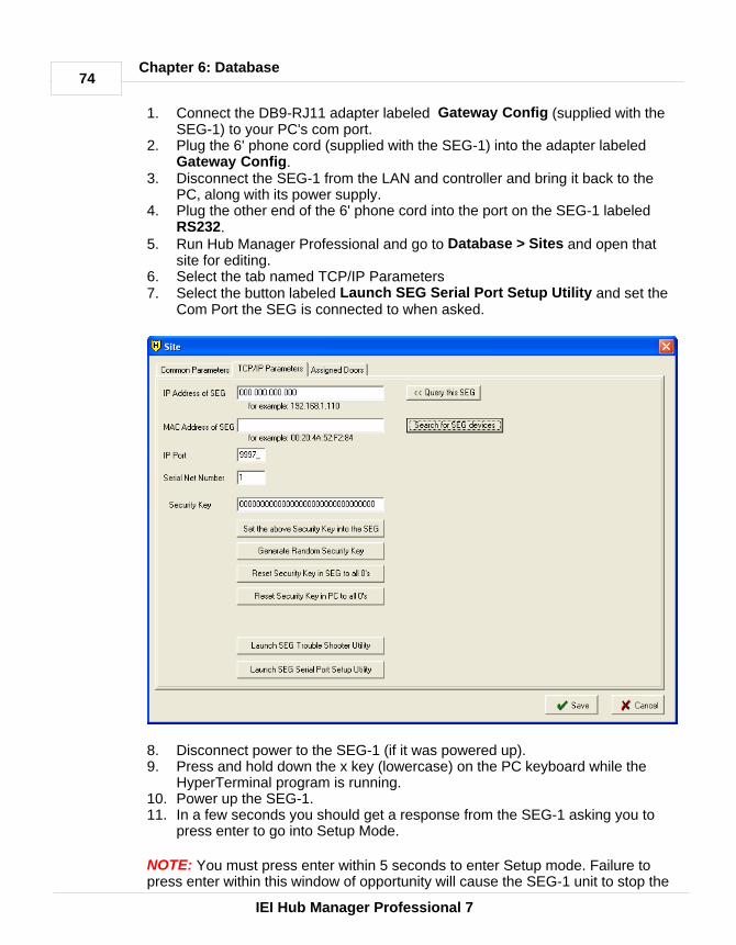
74
IEI Hub Manager Professional 7
Chapter 6: Database
1. Connect the DB9-RJ11 adapter labeled Gateway Config (supplied with theSEG-1) to your PC's com port.
2. Plug the 6' phone cord (supplied with the SEG-1) into the adapter labeledGateway Config.
3. Disconnect the SEG-1 from the LAN and controller and bring it back to thePC, along with its power supply.
4. Plug the other end of the 6' phone cord into the port on the SEG-1 labeledRS232.
5. Run Hub Manager Professional and go to Database > Sites and open thatsite for editing.
6. Select the tab named TCP/IP Parameters7. Select the button labeled Launch SEG Serial Port Setup Utility and set the
Com Port the SEG is connected to when asked.
8. Disconnect power to the SEG-1 (if it was powered up).9. Press and hold down the x key (lowercase) on the PC keyboard while the
HyperTerminal program is running.10. Power up the SEG-1. 11. In a few seconds you should get a response from the SEG-1 asking you to
press enter to go into Setup Mode.
NOTE: You must press enter within 5 seconds to enter Setup mode. Failure topress enter within this window of opportunity will cause the SEG-1 unit to stop the

75
IEI Hub Manager Professional 7
Chapter 6: Database
ability to enter setup mode, and you will see '?!?' displayed on the screen. If thishappens go back to step 7 and start from there again.
12. Release the x key.13. After pressing ENTER to go into setup mode, you will be given a menu
system displaying the current settings and also some menu items to choosefrom (see image below).
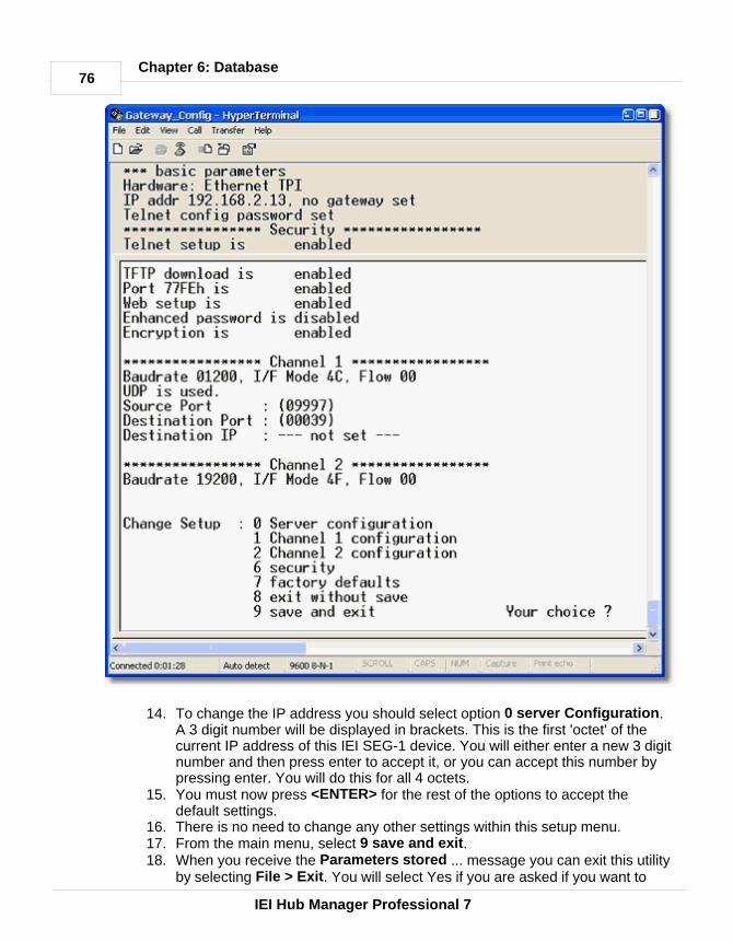
76
IEI Hub Manager Professional 7
Chapter 6: Database
14. To change the IP address you should select option 0 server Configuration.A 3 digit number will be displayed in brackets. This is the first 'octet' of thecurrent IP address of this IEI SEG-1 device. You will either enter a new 3 digitnumber and then press enter to accept it, or you can accept this number bypressing enter. You will do this for all 4 octets.
15. You must now press <ENTER> for the rest of the options to accept thedefault settings.
16. There is no need to change any other settings within this setup menu. 17. From the main menu, select 9 save and exit. 18. When you receive the Parameters stored ... message you can exit this utility
by selecting File > Exit. You will select Yes if you are asked if you want to

77
IEI Hub Manager Professional 7
Chapter 6: Database
disconnect.
NOTE: Default values in all other menu systems should. The default value is keptby pressing the <ENTER> key when that setting is displayed.
Here is a brief description of each menu and sub option, and what the defaultvalues should be. The SEG-1 device is factory set to have the highest securitypossible. Changing any options, especially in the 'Security' menu could result innot having a completely secure environment.
· 0 Server Configuration : · IP Address : (XXX).(XXX).(XXX).(XXX) Allows you to set the IP address
of the IEI SEG-1 directly. You can set it to 0.0.0.0 to allow it to be serveda dynamic IP address each time it boots up. The IP address should onlybe set to 0.0.0.0 if the DHCP server is assigning the same IP address tothis SEG-1 device every time, by way of using a non-expiring IP addresslease that is assigned to the MAC address of the device.
· Set Gateway IP Address : N : (do not change) The term 'Gateway' hererefers to a network router on the LAN not the device you are configuringhere.
· Netmask : 0 (do not change)· Change telnet config password : N (do not change)
· 1 Channel 1 Configuration : Settings of the RS232 port. · Baud Rate: 1200 (do not change)· I/F mode: 4C (do not change)· Flow: 00 (do not change)· Use UDP : Y (do not change)· Source Port = 09997 (If there is a need to change this then make sure to
change the site settings within Hub Manager Professional to match) · Destination Port : 00000 (do not change) · Destination IP: 0.0.0.0 (do not change)
· 2 Channel 2 Configuration : Settings of the RS485 port. · Baud Rate: 19200 (do not change)· I/F mode: 4C (do not change)· Flow: 00 (do not change)
· 6 Security : Here you can change the Encryption key manually to match theencryption key Hub Manager Professional is using. This is normally notnecessary because Hub Manager Professional normally performs this function.After going through this menu item completely, the encryption settings willautomatically be saved and the session will be closed.
· Disable Telnet setup : (Y)· Disable TFTP firmware upgrade : (Y) · Disable port 77FE? : (Y)· Disable web setup? (Y)· Enable encryption? (Y) Encryption must always be enabled, because all
data sent to the SEG-1 is encrypted. Do not disable or communications

78
IEI Hub Manager Professional 7
Chapter 6: Database
with Hub Manager Professional will fail.· XXXXXXXXXXXXXXXXXXXXXXXXXXXXXXXX Change key? (N) This
128 bit security key is changed via the Hub Manager Professionalsoftware. If this security key does not match the key stored in the sitesettings in Hub Manager Professional, then any communication attemptsto your controller hardware will fail.
· 7 Factory Defaults : Sets all options back to out-of-box factory defaults. Afterperforming this function, any security key you had in this device will be deletedand set back to default. In order to speak to this SEG-1 again, you will nowneed follow the directions above to Default the Security Key in Hub ManagerProfessional. Be sure to set a new security key into the SEG-1, using HubManager Professional before you attempt to send sensitive user data to thedoor controllers. This will also set the IP address back to a default value of0.0.0.0.
· 8 Exit Without Save : Cancels any changes you have made in setup.· 9 Save and Exit : Saves any changes you have made in setup and exits
Configuring the IP Address in Hub Manager ProfessionalNow it is time to open Hub Manager Professional, create a new site, and configurethis site to communicate to the SEG-1 with the IP address you have received fromthe IT administrator. This example shows how to set up a SEG-1 connected HubControllers controller network, but the SEG-1 can also be used to communicate toa new type of controller called the "prox.pad plus". The steps are exactly thesame, just the 'Device Group' will be different.
1. Run Hub Manager Professional and login.2. Select Database > Sites and then select the Add button.3. Enter a descriptive Name for this grouping of controllers that will be
communicated with via the SEG-1.4. Select the Device Group drop down list and select the controller family you
are connecting to the SEG-1. For this example, we are going to choose thedevice group named 'HC500, Hub+, HubMax, MaxII'.
5. Select the Connection Type named TCP/IP. 6. Select the tab named TCP/IP Parameters.

79
IEI Hub Manager Professional 7
Chapter 6: Database
7. In the edit box labeled IP Address, enter the IP Address that the ITAdministrator gave you.
NOTE: The MAC Address does NOT need to be defined if you are setting up aSEG with a Static IP Address. The MAC Address is only used if you are assigninga SEG a dynamic IP address via a DHCP server, but that feature also requiresthat the version of SEG firmware be v1.3 or greater. See the chapter named Dynamic IP Address for more information on Dynamic IP Address assignments.
The IP Port and Serial Net Number do not need to be modified in any way.
8. Select Save. 9. Setup of the Static IP Address into the SEG-1 site is complete.
6.4.5 Modem Connection
If you are connecting a via modem to the controllers, then programming of thecontroller is required. The controller must first be programmed for remoteaccess and modem string. For details, see the controller documentation. Toselect the Sites option, select Database > Sites. The Sites screen displays.

80
IEI Hub Manager Professional 7
Chapter 6: Database
Field/Button Description
Port Communications port to use for the site being added; selected from adrop-down list.
Phone NumberPhone number for the site being added. To access an outside line, dialOptional digit to dial, if necessary, to get an outside line.
Predefined ModemDrop-down list that allows you to select the type of modem being used forthis site. Choosing a predefined modem automatically loads the Init, Dial,and Hangup strings for that particular modem. Installation of modemdrivers is not necessary.
Currently four (4) modems are qualified for the personal computer side.Installation of a modem driver is not necessary. Available modems are:Boca Modem 14.4KBoca Modem 33.6KU.S. Robotics Modem 33.6KU.S. Robotics Modem 56K
Init StringSpecifies the communications initialization string for the site being added.
Dial StringSpecifies the communications dial string for the site being added.
Hangup string Specifies the communications hangup string for the site being added.
Number of Redials Specifies the number of redials for the site being added.
Seconds between RedialsSpecifies the number of seconds to wait between redial attempts.
Check modem before dialingSpecifies that the program check the modem to ensure it is online beforedialing.

81
IEI Hub Manager Professional 7
Chapter 6: Database
6.4.6 Managing Stand-Alone Controllers
A 'Stand-Alone' site is a grouping of controllers which have no physicalcommunications connection, because those controllers either have nocommunications capability, or it is not possible to connect to that controllerphysically. Hub Manager Professional can only manage the user lists of thesedevice types. There are no settings for this Site type.
Hub Manager Professional 7 allows you to manage the user codes of your 60,120, or 2000 user Stand-Alone (non-networked) keypads such as the following: 60 User: 234120 User: 212, 232, 233, 242, LS12000 User: prox.pad
To manage these types of devices, follow these steps:1. Create a new site 2. Set the name of this grouping of controllers.3. Set the Device Group as 'Stand-Alone'
4. The Connection Type will be automatically set to 'No Connection'.5. Select Save.6. Select Database > Doors and select Add

82
IEI Hub Manager Professional 7
Chapter 6: Database
7. Select the Stand-Alone site you just created.8. Set the Device Type to the capacity of that Stand-Alone keypad you want to
manage. For example, if you are going to manage a 212i, you would selectthe '120 User' option as the device type. Hub Manager Professional 7 will notallow any management of System Options or System Parameters forStand-Alone devices.
Now you can manage the system just as you would with networked devices. If youwish to get a printout of the User locations and the Codes or Cards for thoselocations, in order to help you program the controller, just go to Reports >Database and select the Doors report. You can now print this report to a hardcopyand use it as a guide to manually program the user codes into the controller usingthat devices manual programming commands.
6.5 TimeZones
Time Zones are used for two purposes: (1) to specify the days and times when a users access credentials are valid (2) to specify the auto-unlock schedules of the door controllers The auto-unlocksettings are established in the door settings for each door controller.
Time Zone is defined by its beginning and end times and days of the week whenthis Time Zone is valid. Hub Manager Professional also lets you specify whetherholidays defined in the Holiday Database should be included in the particularTime-zone. Enabling Holidays means that this Time Zone is provided access ondefined holidays. To select the Time Zones option, select Database > TimeZones. The Time Zones screen displays.
The "Sort" field lists the sort criterion for this option. Time Zones can be sorted byName, Type, Start and Stop.
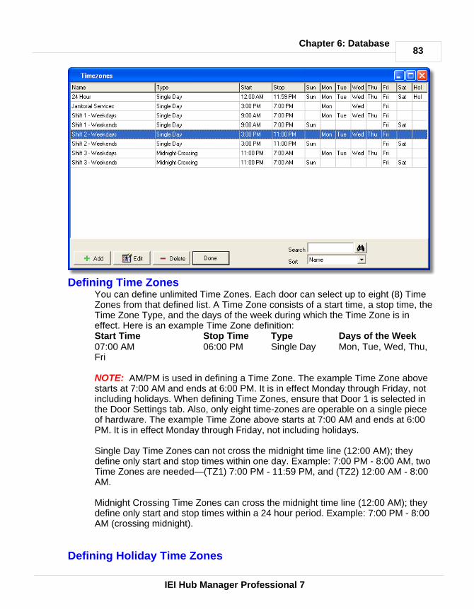
83
IEI Hub Manager Professional 7
Chapter 6: Database
Defining Time ZonesYou can define unlimited Time Zones. Each door can select up to eight (8) TimeZones from that defined list. A Time Zone consists of a start time, a stop time, theTime Zone Type, and the days of the week during which the Time Zone is ineffect. Here is an example Time Zone definition:Start Time Stop Time Type Days of the Week07:00 AM 06:00 PM Single Day Mon, Tue, Wed, Thu,Fri
NOTE: AM/PM is used in defining a Time Zone. The example Time Zone abovestarts at 7:00 AM and ends at 6:00 PM. It is in effect Monday through Friday, notincluding holidays. When defining Time Zones, ensure that Door 1 is selected inthe Door Settings tab. Also, only eight time-zones are operable on a single pieceof hardware. The example Time Zone above starts at 7:00 AM and ends at 6:00PM. It is in effect Monday through Friday, not including holidays.
Single Day Time Zones can not cross the midnight time line (12:00 AM); theydefine only start and stop times within one day. Example: 7:00 PM - 8:00 AM, twoTime Zones are needed—(TZ1) 7:00 PM - 11:59 PM, and (TZ2) 12:00 AM - 8:00AM.
Midnight Crossing Time Zones can cross the midnight time line (12:00 AM); theydefine only start and stop times within a 24 hour period. Example: 7:00 PM - 8:00AM (crossing midnight).
Defining Holiday Time Zones

84
IEI Hub Manager Professional 7
Chapter 6: Database
When you define a Time Zone, you can specify whether or not it is to be in effecton holidays by using the "Holiday" checkbox. The Door Setup Holidays List is usedto specify the dates that are to be considered holidays by the system. Placing acheckmark next to "Holidays" directs the program to grant access on definedholidays.
Printing Time Zone DefinitionsTo print the Time Zone definitions, select Reports > Database from the mainmenu and then check the Time Zones box in the Printing of Databases screen.
Single-Day Time Zone
Midnight-Crossing Time Zone

85
IEI Hub Manager Professional 7
Chapter 6: Database
Adding a Time Zone1. Select the Add button on the Time Zone screen. The Add a Time Zone
screen displays. 2. Enter the name of this new time zone in the Name field (maximum 18
characters), the beginning and ending times in the corresponding fields (useAM/PM time format), select the Time Zone Type, check the days of the weekto which this time zone should apply (on the right side), and select SAVE tosave the information to the time zone database.
Editing a Time ZoneEditing an existing time zone is very similar to adding a new one.1. Highlight the time zone you wish to edit, and select the EDIT button on the
Time Zone screen. The specified Time Zone screen displays.2. Modify the information as required.
Deleting a Time ZoneDeleting an existing time zone is easy.1. Highlight the time zone you wish to delete, and select the DELETE button on
the Time Zone screen. The software displays a delete confirmation prompt.Only Time Zones not assigned to an Access Level can be deleted.
2. Select OK or CANCEL as desired.
Searching for a Time ZoneYou can search the time zone database for a particular time zone record. Enterthe time zone's name in the "Search" text box on the Time Zone screen and selectthe Binocular button or press the <Enter> key.

86
IEI Hub Manager Professional 7
Chapter 6: Database
6.6 Doors
A door is defined as any entry point (doors with electrical or magnetic lock, turnstile,rising barrier, or motorized gate) controlled by a supported Controller. The Doorsdatabase stores detailed information about door controller setup parameters. The Hub Manager Professional program can export/import to all controllers in a site. Toselect the Doors option, select Database > Doors. The Doors directory screendisplays. The Door directory shows all doors in all sites. You can double-click anydoor to edit that doors options.
Adding a Door1. Select the Add button on the Door screen. The Door screen displays.
2. Enter the name for the door controller you are adding. 3. Select the Site this door is being added to.4. Select the Controller Type.5. Specify the Controller Address (if required by the selected controller type).
NOTE: PDA connected controllers don't ask you to specify a Controller

87
IEI Hub Manager Professional 7
Chapter 6: Database
Address.6. Modify any of the System Parameters. Parameters are typically timer values.7. Select the Options tab and modify any of the Options as required. Options are
typically features that can be either enabled or disabled.
8. Disable any of the Log Events from being recorded. Clearing a checkbox nextto a particular event means that event will not be recorded in the controllerwhen that event occurs. This can be helpful if you find that a particular eventis occurring too often and is filling up the transaction log buffer, is thereforeand causing other important events to be discarded, since the buffer isfirst-in, first-out. Common events that are typically disabled for this purposeare: Access Denied and Request to Exit.
9. Select the Time Zones tab to view the time zones assigned to the door youare adding. Available Time Zones are listed on the left. Selecting one of thesedisplays the details at the bottom of the screen. Selecting the right arrow ordouble-clicking the Time Zone on the left causes this Time Zone to move tothe right side which means this Time Zone is assigned to this controller. Up toeight (8) Time Zones can be selected for any one door controller. Placing acheck mark into the checkbox of a selected Time Zone makes that TimeZone an auto-unlock Time Zone.

88
IEI Hub Manager Professional 7
Chapter 6: Database
10. Select Save to save the information to the doors database, or select Cancelto discard all changes and return to the Doors directory.
Common Door Settings Name
Name of the door.Site
Identifies the site to which door is being added. A site is more or less a group ofdevices that share a common connection type and a common communicationsprotocol.
Controller TypeSpecifies the type of controller you have controlling this door.
Controller Address Two-digit number that corresponds to the actual address programmed in thisparticular door controller.
NOTE: The Controller Address field is not visible when a PDA connectedcontroller type is selected, such as the LS2\P.

89
IEI Hub Manager Professional 7
Chapter 6: Database
System Options "Options" usually have an ON/OFF value. Placing a checkmark in the box next tothe options typically enables this feature. But there are some options that togglebetween 2 choices.
System Parameters"Parameters" usually have an integer value denoting a count or a timer value. Butsome values may reference a single value of several options.
Here is a chart showing what features and options are supported by each devicetype. The ranges are listed in seconds.
Feature HC500 Hub+\Max MaxII v1 MaxIIv2
LS2\P prox.padplus
Lock Timer 1-90 sec 1-90 sec 1-90 sec 1-90sec
1-255 sec 1-255 sec
Forced DoorTimer
0-990sec
0-990 sec 0-990 sec 0-990sec
0-990 sec 0-990 sec
Door Ajar Timer (Propped Door)
1-990sec
1-990 sec 1-990 sec 1-990sec
1-990 sec 1-990 sec
Log Event Mask X X X X XError LockoutCount
1-50incorrect
tries
1-50 incorrect
triesError LockoutDuration
1-255 sec 1-255 sec
Audio Alerts XKeypressFeedback-Audible
X X X X X X
KeypressFeedback - Visual
X X X X X X
First In AutoUnlock TimeZones
X X X X
Auto Unlock TimeZones
1 8 8 8 8 8
Auto-Entry Count X XDaylight SavingsTime Auto Adjust
X X X
Daylight SavingsTime Date Format
X X X
Lock Prior toSleep
X
Card AND CodeProgramming
X X
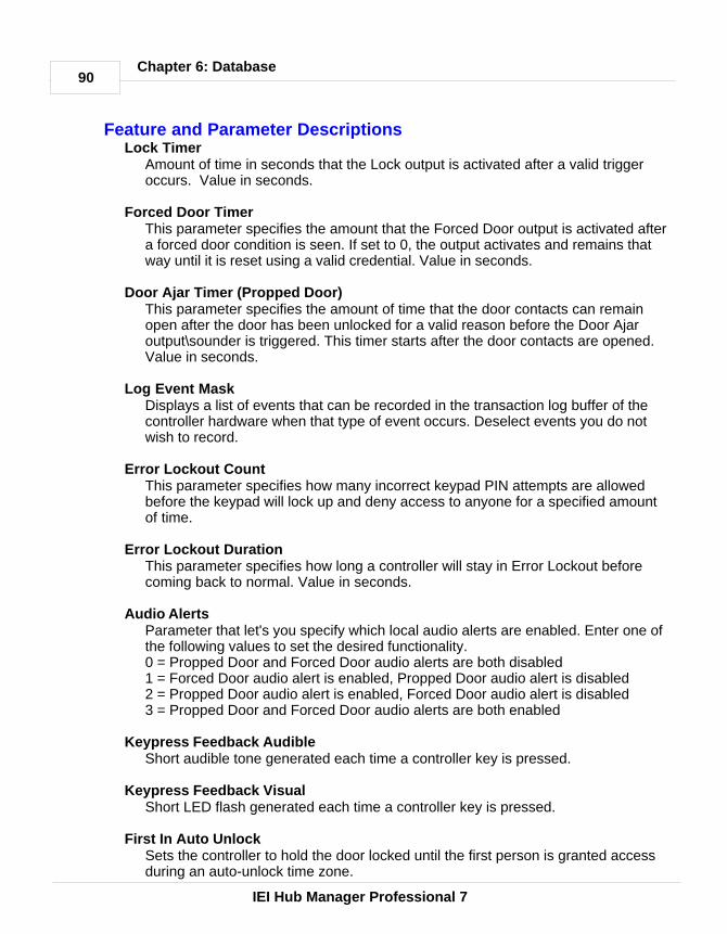
90
IEI Hub Manager Professional 7
Chapter 6: Database
Feature and Parameter DescriptionsLock Timer
Amount of time in seconds that the Lock output is activated after a valid triggeroccurs. Value in seconds.
Forced Door TimerThis parameter specifies the amount that the Forced Door output is activated aftera forced door condition is seen. If set to 0, the output activates and remains thatway until it is reset using a valid credential. Value in seconds.
Door Ajar Timer (Propped Door)This parameter specifies the amount of time that the door contacts can remainopen after the door has been unlocked for a valid reason before the Door Ajaroutput\sounder is triggered. This timer starts after the door contacts are opened.Value in seconds.
Log Event MaskDisplays a list of events that can be recorded in the transaction log buffer of thecontroller hardware when that type of event occurs. Deselect events you do notwish to record.
Error Lockout CountThis parameter specifies how many incorrect keypad PIN attempts are allowedbefore the keypad will lock up and deny access to anyone for a specified amountof time.
Error Lockout DurationThis parameter specifies how long a controller will stay in Error Lockout beforecoming back to normal. Value in seconds.
Audio AlertsParameter that let's you specify which local audio alerts are enabled. Enter one ofthe following values to set the desired functionality.0 = Propped Door and Forced Door audio alerts are both disabled1 = Forced Door audio alert is enabled, Propped Door audio alert is disabled2 = Propped Door audio alert is enabled, Forced Door audio alert is disabled3 = Propped Door and Forced Door audio alerts are both enabled
Keypress Feedback AudibleShort audible tone generated each time a controller key is pressed.
Keypress Feedback VisualShort LED flash generated each time a controller key is pressed.
First In Auto UnlockSets the controller to hold the door locked until the first person is granted accessduring an auto-unlock time zone.
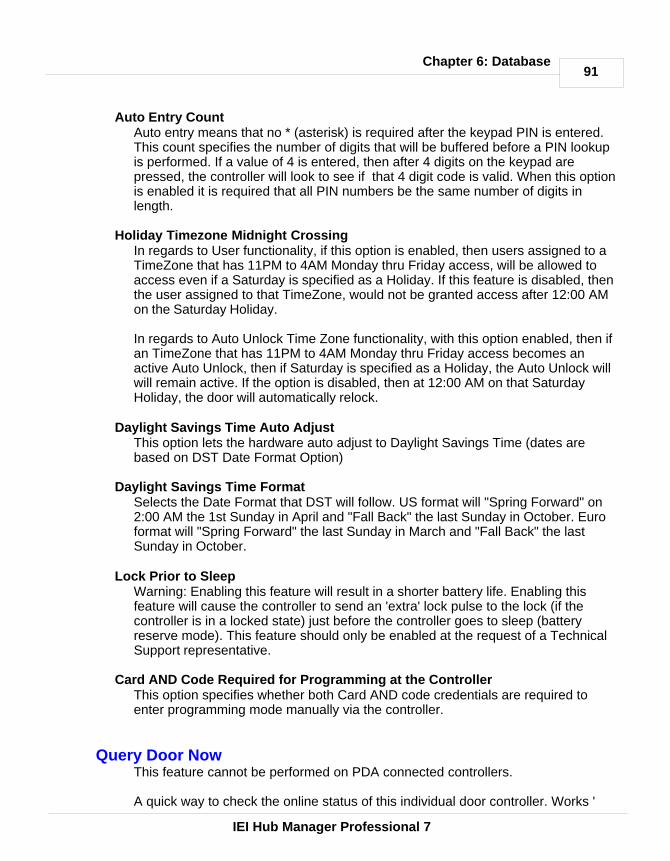
91
IEI Hub Manager Professional 7
Chapter 6: Database
Auto Entry CountAuto entry means that no * (asterisk) is required after the keypad PIN is entered.This count specifies the number of digits that will be buffered before a PIN lookupis performed. If a value of 4 is entered, then after 4 digits on the keypad arepressed, the controller will look to see if that 4 digit code is valid. When this optionis enabled it is required that all PIN numbers be the same number of digits inlength.
Holiday Timezone Midnight CrossingIn regards to User functionality, if this option is enabled, then users assigned to aTimeZone that has 11PM to 4AM Monday thru Friday access, will be allowed toaccess even if a Saturday is specified as a Holiday. If this feature is disabled, thenthe user assigned to that TimeZone, would not be granted access after 12:00 AMon the Saturday Holiday.
In regards to Auto Unlock Time Zone functionality, with this option enabled, then ifan TimeZone that has 11PM to 4AM Monday thru Friday access becomes anactive Auto Unlock, then if Saturday is specified as a Holiday, the Auto Unlock willwill remain active. If the option is disabled, then at 12:00 AM on that SaturdayHoliday, the door will automatically relock.
Daylight Savings Time Auto AdjustThis option lets the hardware auto adjust to Daylight Savings Time (dates arebased on DST Date Format Option)
Daylight Savings Time FormatSelects the Date Format that DST will follow. US format will "Spring Forward" on2:00 AM the 1st Sunday in April and "Fall Back" the last Sunday in October. Euroformat will "Spring Forward" the last Sunday in March and "Fall Back" the lastSunday in October.
Lock Prior to SleepWarning: Enabling this feature will result in a shorter battery life. Enabling thisfeature will cause the controller to send an 'extra' lock pulse to the lock (if thecontroller is in a locked state) just before the controller goes to sleep (batteryreserve mode). This feature should only be enabled at the request of a TechnicalSupport representative.
Card AND Code Required for Programming at the ControllerThis option specifies whether both Card AND code credentials are required toenter programming mode manually via the controller.
Query Door Now This feature cannot be performed on PDA connected controllers.
A quick way to check the online status of this individual door controller. Works '
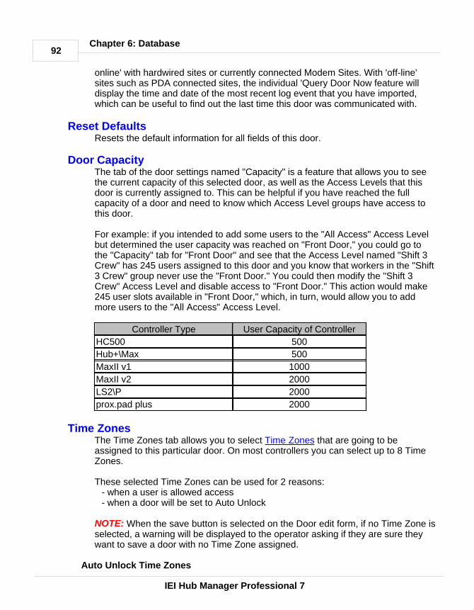
92
IEI Hub Manager Professional 7
Chapter 6: Database
online' with hardwired sites or currently connected Modem Sites. With 'off-line'sites such as PDA connected sites, the individual 'Query Door Now feature willdisplay the time and date of the most recent log event that you have imported,which can be useful to find out the last time this door was communicated with.
Reset DefaultsResets the default information for all fields of this door.
Door CapacityThe tab of the door settings named "Capacity" is a feature that allows you to seethe current capacity of this selected door, as well as the Access Levels that thisdoor is currently assigned to. This can be helpful if you have reached the fullcapacity of a door and need to know which Access Level groups have access tothis door.
For example: if you intended to add some users to the "All Access" Access Levelbut determined the user capacity was reached on "Front Door," you could go tothe "Capacity" tab for "Front Door" and see that the Access Level named "Shift 3Crew" has 245 users assigned to this door and you know that workers in the "Shift3 Crew" group never use the "Front Door." You could then modify the "Shift 3Crew" Access Level and disable access to "Front Door." This action would make245 user slots available in "Front Door," which, in turn, would allow you to addmore users to the "All Access" Access Level.
Controller Type User Capacity of Controller
HC500 500
Hub+\Max 500
MaxII v1 1000
MaxII v2 2000
LS2\P 2000
prox.pad plus 2000
Time ZonesThe Time Zones tab allows you to select Time Zones that are going to beassigned to this particular door. On most controllers you can select up to 8 TimeZones.
These selected Time Zones can be used for 2 reasons:- when a user is allowed access- when a door will be set to Auto Unlock
NOTE: When the save button is selected on the Door edit form, if no Time Zone isselected, a warning will be displayed to the operator asking if they are sure theywant to save a door with no Time Zone assigned.
Auto Unlock Time Zones

93
IEI Hub Manager Professional 7
Chapter 6: Database
1. To specify that a Time Zone is to be used for the doors auto-unlock schedule,you first add Time Zones to the Time Zone directory,
2. you then edit the door, select the Time Zones tab, and select the Time Zoneson the left that you want to be assigned to that door.
3. Now place a checkmark next to the Time Zone on the right to specify thatyou want the door to unlock automatically at this time.
NOTE: If you have enabled 'First In Auto-Unlock' for this door, then every TimeZone that is setup as Auto-Unlock will function as a First In Auto Unlock TimeZone. This means that a valid user must enter during that Time Zone before thecontroller will allow the door to remain unlocked for that specified time zoneperiod. First In Auto Unlock is enabled by default, in order to create a more secureenvironment. If you want the doors to Auto Unlock without the need for a user tocome in first, then you can simply disable the 'First In Auto Unlock' in the doorsoptions screen.
Any number of the selected Time Zones can be set to Auto Unlock by placing acheckmark next to it.
6.6.1 Hub Controllers
Here is a chart to help identify which Hub Controllers type you have, based on theinformation that appears on the Hub controllers firmware label and any physicaltraits it may have.
ControllerType
Info on the firmware label
Physical Identities
HC500 v2.x or greater Comes in a plastic singlegang box
Hub+/Max v1.x P or greater Comes in a plastic singlegang box, or Hub Max can
Max II v1 v2.0 or v2.1 Comes in a Hub Max orMini Max can
Max II v2 v2.2 or greater Comes in a Hub Max orMini Max can
6.6.2 prox.pad plus
The prox.pad plus controllers work on a RS-485 network bus and cannot beplaced on the same network bus as the HC500, Hub+, HubMax, Max II v1 or MaxII v2 controllers. If you want to use both Hubs and prox.pad plus in the sameaccess control system, then a separate Site must be created for the prox.pad pluscontrollers, and a separate 485 multi drop wire run must be made for the prox.padplus controllers.
Basic Characteristics: (subject to change, for a full up-to-date list of all prox.pad plusfeatures and specifications, contact your Access Control / Alarm Dealer)

94
IEI Hub Manager Professional 7
Chapter 6: Database
· 2000 Users· 16 Single Date Holidays· 16 Block Holidays· 8 Time Zones· Up to 8 Auto Unlock Time Zones · 2000 Event Transaction Log Buffer· 1 Lock Relay · 1 Auxiliary Relay, which can be assigned to one of the following functions:
Alarm Shunt, Forced Door, Door Ajar, Panic, or Duress.· Invalid Code Lockout Count· Invalid Code Lockout Duration· Daylight Savings Time (DST) Auto Adjust· Option to require "Card AND Code" to Enter Programming Mode· Timed Anti-Passback· 1st In Auto Unlock· Prox Antenna can be remoted from the controller, up to 10' away.· User Types including: Emergency, Extended Unlock (for slower moving
people), Lockout, Single-Use, and others· Only new events are imported from the controller, which reduces the log import
time.· During communications with the controller, such as exporting data or importing
event logs, the controller continues to allow access through the door· Option to use the Local Sounder for Forced Door or Door Ajar· Up to 32 controllers may be networked on a single 485 loop, additional prox.pad
plus networks (Sites) may be added to the software as needed· This controller can be communicated with over a TCP/IP LAN/WAN network
using IEI SEG-1 device
Communicating with a DoorCommunications with prox.pad plus controllers is the same process ascommunicating with Hub controllers. You will select that Site from the Sitedirectory, then select connect, and now you can perform any exports or importswith the doors of that site.
6.6.3 LS2\P
The LS2\P controllers work in conjunction with the LS Link.
Basic Characteristics: (for a full up-to-date list of all LS2\P features andspecifications, contact your Access Control / Alarm Dealer)
· 2000 Users· 16 Single Date Holidays· 16 Block Holidays· 8 Time Zones

95
IEI Hub Manager Professional 7
Chapter 6: Database
· Up to 8 Auto Unlock Time Zones · 2000 Event Transaction Log Buffer· Invalid Code Lockout Count· Invalid Code Lockout Duration· Daylight Savings Time (DST) Auto Adjust· Option to require "Card AND Code" to Enter Programming Mode· Auto Unlock as well as First In Auto Unlock· User Types including: Emergency, Extended Unlock (for slower moving
people), Lockout, Single-Use, Panic, Passage and others.
6.6.4 Door Wizard
The Door Level Wizard presents you with a step-by-step process for adding doorto the system. This wizard was created to allow you to create doors with the leastamount of effort required. It will also help you to assign consistent settings to thedoors you are creating.
Although this wizard may make it easier to add a single door to the system,because of the step by step nature of the wizard, the true benefits will be seen if, for example, you are adding 10 doors to 2 different sites (20 doors total). Adding20 doors and setting up the options and Time Zones without the wizard takesapproximately 240 mouse clicks, but with the Wizard it may only take 12 clicks,because what you are setting up for one door is only done once for all doors beingcreated.
Initial Step - How many doors to add where to add them· The initial choice you must make is whether or not you want to use the wizard to
add multiple doors, and also if you want to add these doors to multiple sites.This Wizard was designed to allow a fast and efficient setup of many types ofsystems for different applications.
· Some of the content in the following steps may change due to the initial optionyou selected but the concept of that step is still the same.
Step 1 of 3 - Door SettingsStep 1 is where you specify the number of doors (if applicable), and the site(s) towhich the doors(s) are being added to.
Step 2 of 3 - Door Options· This step is where you select which door options and log event masks to enable
or disable. Any selections you make here will be applied to all the doorscurrently being added with the wizard.
· Any of the options of a door can be customized after the doors have beencreated.
Step 3 of 3 - Time Zone Selection

96
IEI Hub Manager Professional 7
Chapter 6: Database
· This is where you specify what Time Zones will be assigned to these doors youare adding.
· Time Zones can be assigned, by placing a checkmark in the column labeled'Selected' .
· Auto-unlock Time Zones can be specified, by placing a checkmark in thecolumn labeled 'Auto Unlock'.
· Any of the Time Zone assignments of a door can be customized after the doorshave been created.
Final Option For Multiple Doors· If you chose to add multiple doors, the last option will ask how you want to
name and number these doors. · You can choose to let the wizard add all the doors now and give them names
like 'Door 1' , 'Door 2', etc... · You can also have the Wizard prompt you for the names (and possibly the
controller addresses) one after the other.
6.7 Access Levels
The Access Levels option completes the access control definition of where andwhen a user can go within the system by associating the users access credentialswith one or more doors (where), one or more time zones (when), and a user type (how), which defines what action is to be performed when a user presents a validcredential to that controller. Access levels defines where and when a users' userscredential is valid within the entire access control system.
Users can be assigned to an Access Level that has no doors assigned to it. Awarning message will appear, asking if you are sure you want to do this, but theoperator can choose to override the warning. This allows the operator to create anAccess Level called "NONE" (for example) that has no doors assigned to it, andthen simply re-assign users to that Access Level. That user is now, in effect,disabled, because he has access to no doors. Make sure you export afterreassigning a user like this, this will ensure that the user has been removed fromthe controllers.

97
IEI Hub Manager Professional 7
Chapter 6: Database
Access levels provide Hub Manager Professional system administrators apowerful tool to quickly and efficiently maintain the system users. This is especiallyimportant for large systems, with large number of users and various securityrequirements (zoned security approach). When a system administrator creates anew user, the system administrator allocates only an access level to the new user.This simplifies system administration as the access level automatically contains allinformation about which doors this user is allowed to enter and during whichtimes. It is not necessary to program individual users for access to eachdoor in the system.
NOTE: This section on Access Levels and the System Administrator merit specialattention. Please ensure that you understand these sections before you add or editAccess Level information. To select the Access Levels option, select Database >Access Levels. The Access Levels screen displays.
Adding an Access Level1. Select the Add button on the Access Levels screen. The Access Level Detail
screen displays. 2. Enter the Name for the new access level.3. Select one of the available sites to display the available doors at the selected
site.4. Select one of the available doors at the selected site to which you wish to
provide access.5. Expand the User Type drop down list to display the user type options, and
then select the user type that you want to assign to a user of this particularaccess level that is granted access to this particular door. User Types are

98
IEI Hub Manager Professional 7
Chapter 6: Database
explained in more detail below.6. Expand the Access Condition drop down list to display the access condition
options, and then select which combination of keypad code and access cardcredential is necessary to perform the action of the user type, such as grantaccess to this door. Specifying Card AND Code requires that both credentialsbe entered to perform the action of this user type, whereas Card OR Codejust requires that one or the other be entered.
7. Place a checkmark in the checkbox next to a Time Zone to indicate the timesat which users assigned this access level will be granted access to theselected door. Any combination of the Time Zones can be selected for thatparticular door.
8. Repeat steps 3-7 for each door to which you wish to provide access. 9. Select Save to save the data to database. To discard all edits and cancel the
addition of an access level, select the Cancel button.
Field/Button DescriptionName
Text box that you use to specify the name of the access level.Site Name, Door Name, User Type, Access Condition
Specifies the site name, door name, user type, and the access condition requiredto access the selected door.
Selected, Time Zone Name, Start, Stop, Days Specifies whether or not the time zone is "selected" to operate on this door for thisparticular Access Level.
Deny access to the selected door Selecting this button removes the selected door from this access level'sprivileges.
Notify me when I attempt to add users to this particular Access LevelEnabling this option will cause a notification message to appear any time theOperator attempts to add a user and tries to assign that new user to this AccessLevel. This can be useful if you want to be warned anytime you grant assign auser to an Access Level you have given full access privileges to.
SaveSaves current door data to Access Levels database.
CancelDiscards all edits and returns to previous screen without saving data.
User TypesComm Unlock - Import \ Export
Presentation of a valid credential by this user type unlocks communications ondevices that support this user type, and allows both Log imports and Data exports.This user type does not unlock the door.
Emergency This user type cannot be locked out or disabled. Presentation of a valid credentialby this user type will override any locked condition and will unlock the door,including User Lockout and Panic (lockdown) states. This user type will unlock the

99
IEI Hub Manager Professional 7
Chapter 6: Database
door for the time specified in the Door Settings screen under "Lock Timer -Extended Users".
Extended Time Presentation of a valid credential by this user type unlocks the door for a longerperiod than a standard user would unlock the door for. A good use is for physicallyimpaired users that require more time to get to the door after their credential hasused to unlock the door. The 'Extended Unlock' timer is specified in the doorsettings of that individual door.
Lockout Presentation of a valid credential by a Lockout user type will cause all users in thatcontroller to not be able to gain access until another valid lockout code is enteredagain.
The state of the lock does not change when a Lockout code is entered. Lockoutusers cannot be used to gain access.
Enabling Lockout is useful if there has been a danger identified in a particularroom or area and you do not want anyone to enter until the danger is cleared. Toclear the Lockout condition you must enter a Lockout code again. During thelockout condition the following users types are still allowed to gain access: Master,Supervisor, and Emergency.
MasterThe User List contains, as its first user on the list, the Master Code. This user hasa special function. Its access credential is equivalent to the Master Code in acontroller.
The factory-default access code for this user is "1234." This code is sent to everycontroller in the system and is placed into user location 1.
This user is not assigned to an Access Level, because it is not possible to editwhich doors this user will go to.
Any time a new door controller is added to the system, it will automatically receivethe "Master Code" when data is exported to this controller.
This user can be used as a "communications unlock" code, which is required forPDA communications with the LS2\P controllers.
PanicPresentation of a valid credential by this user type will lock the controller no matterwhat unlock state it is in (much like the Relock user type) and it will also willlockout all other users from using the controller (much like the Lockout user type).This is useful if there has been a crisis scenario identified outside of a securedarea and you do not want the crisis to move into the secured area. By entering thistype of user code, you will lock the door and no one else will be allowed to unlock

100
IEI Hub Manager Professional 7
Chapter 6: Database
the door using a standard unlock code. Only the Master Code, Supervisor Code,or Emergency codes can be entered to gain access and clear the Panic (lockdown) condition.
Passage Presentation of a valid credential by this user type causes the following to occur: Ifthe door is locked, it is unlocked and latched in the unlock state. If the door isunlocked due to a previous Passage code, it is relocked.
NOTE: Passage users are inoperative during an active auto-unlock time zone.
Relock This user type locks the door if the door is in an unlocked state. This function isuseful when a door is unlocked by an Auto-Unlock Time Zone and you wish torelock the door before the scheduled lock time. Relock users lock a door unlockedfor any reason. Relock users can't unlock a door.
Single Use (One Time Use)Presentation of a valid credential by this user type will unlock the door as aStandard User will, but the code is accepted by that particular controller only once.A Single Use code is only exported to a device one time, to make sure that thecode does not get sent again after it is used.
NOTE: If the only change you made in the software was to enable a Single Useuser, and then you choose to export, you may receive a message of 'No changessince the last export', but don't be alarmed, you can be assured that the SingleUse codes were actually exported as enabled. This message is just a side effectcaused by the way Hub Manager Professional processes Single Use codesseparate from the rest of the other data. If you are using a PDA connectedcontroller, then a HotSync is still required after enabling the Single Use User.
Standard AccessPresentation of a valid credential by this user type unlocks the door for thepre-determined Lock Timer specified in the Door Settings.
NOTE: The users named 'Master User' and 'Supervisor User' are special usersand are described in the Users section. The Master User is sent to user location 1in all controllers and the Supervisor User is sent to user location 2 in all controllersthat support that user type. Some controllers allow you to define any number ofSupervisor Users.
SupervisorPresentation of a valid credential by this user type unlocks the door for thepre-determined Lock Timer value (1-255 seconds) as set in the Door Settingsscreen. Presentation of a valid credential by this user type also unlockscommunications, so that the controller can be programmed with a PDA running LS Link.

101
IEI Hub Manager Professional 7
Chapter 6: Database
In LS2\P and prox.pad plus controllers, the user named 'Supervisor User' in theuser directory will be sent to user location 2 of each LS2\P controller.
NOTE: Supervisor Users should normally not be used to gain access to batterypowered controllers. Using this User Type on a regular basis to gain access willunnecessarily reduce battery life, since this User Type unlocks communicationsand keeps the controller powered up for up to 60 seconds.
Supported User Types Here's a chart to show the user types supported by each controller type, and howmany of each User Type are allowed in a particular controller type (up to the usercapacity of that specific controller type).
User Type HC500, Hub+\Max
MaxII v1, MaxII v2
LS2\P prox.pad plus
Com Unlock -Import \Export
No Limit No Limit
Emergency No Limit No Limit
ExtendedTime
No Limit No Limit
Lockout No Limit No Limit
Master 1 (required) 1 (required) 1 (required) 1 (required)
Panic No Limit
Passage No Limit No Limit No Limit No Limit
Relock No Limit No Limit No Limit
Single Use No Limit No Limit
Standard No Limit No Limit No Limit No Limit
Supervisor 1 (required) 1 (required)
Printing Access LevelsSelect Reports > Database from the main menu and then select the AccessLevel checkbox on the subsequent screen, and specify the desired output device.

102
IEI Hub Manager Professional 7
Chapter 6: Database
6.8 Access Level Wizard
The Access Level Wizard presents you with a step-by-step process to creating anAccess Level that can be assigned to users. This wizard was created to allow youto create an access level with the least amount of effort (mouse clicks) required.The wizard will also help you to create consistent access privileges to the doorsyou have selected. If you choose to apply all the settings you specify to everyselected door by leaving the default 'YES' option selected in steps 3, 4, and 5,every door you selected in step 2 will be setup the exact same way in only 3 or 4clicks of the mouse.
Step 1 of 5 - Name the Access Level· It is recommended that you chose a name that describes the type of people that
will be assigned to this Access Level, such as 'Accounting Manager','Accounting Staff', 'Production Manager', 'Production Staff', 'All Access', or even'Relock All'
· Anyone assigned to this Access Level will have the exact same accessprivileges as every other member of this Access Level.
· The name you assign can be changed at any time after the Access Level iscreated.
Step 2 of 5 - Door Selection· This step is where you are going to select which doors members of this Access
Level will have access to. · If this Access Level will have access to any door in the system, just leave the
'YES' selected, otherwise choose 'NO' and select the appropriate doors.
Step 3 of 5 - User Type Selection· This is where you specify what action will occur when users assigned to this
Access Level enter their valid credential.

103
IEI Hub Manager Professional 7
Chapter 6: Database
· If you want to assign the same User Type to all selected doors leave the 'YES'option selected, otherwise select 'NO' and use the combo box in the right mostcolumn to make the appropriate user type selection for each door.
Step 4 of 5 - Access Condition Selection · This is where you specify what type of code or card combination is required of
users assigned to this Access Level. · If you know you have front ends/controllers that support only one type of code
input, you should select 'PIN OR Card'. · If you know you have front ends/controllers that support and require that both a
code and card to be presented before access is granted, then you should select'PIN AND Card'.
· Only those Access Conditions that are supported by all device types will bedisplayed.
· If you want to assign the same Access Type to all selected doors leave the'YES' option selected, otherwise select 'NO' and use the combo box in the rightmost column to make the appropriate access condition selection for each door.
Step 5 of 5 - Time Zone Assignments· This is where you specify what Time Zones users assigned to this Access Level
will be granted access during.· By default, the 'YES' option is selected, and in the bottom grid, the wizard will
only show Time Zones that appear in every one of the selected doors from step2. If this grid is empty, that means there isn't a common Time Zone thatappears in every door, and you must now select 'NO' because the Time Zoneselections must be made for each individual door.
· Select (click on) one of the doors and the Time Zones assigned to that doorswill appear at the bottom. If no Time Zones appear at the bottom that means aTime Zone was never assigned to that door when it was created. You must nowdecide what you want to do. You can either go back to step 2 and deselect thatdoor, and then finish creating this access level, and add that door afterwards.
· You could also decide to cancel adding this Access Level and go back and addthe Time Zone to that door and come back to the Wizard to re-create theAccess Level. Either way, you will need to go to that door and assign a TimeZone to it.
· Every selected door from step 2 must have a time Zone selection made in Step5.
6.9 Users
The Users option lets you add new users to the system and specify the accesscredentials for each user. You can also edit existing user records, delete them,search for particular user records, and print all user records in the user database.To select the Users option, select Database > Users. The Users screen displays.User information is shown and an "Add Group" button is added to facilitate thecreation of a batch of users at one time. Available sort criteria is listed in the "Sort"

104
IEI Hub Manager Professional 7
Chapter 6: Database
drop-down list [First Name, Last Name, Card, PIN, RF Fob, Raw Data, Visual ID,or Access Level].
The User List Import Wizard option lets you create users and import the usernames from an external list in a simple step-by-step procedure.

105
IEI Hub Manager Professional 7
Chapter 6: Database
Adding a User1. Select the Add button on the Users screen. The User edit screen displays. 2. Enter the information as required.3. Select Save to save the settings. To cancel the adding\editing this particularuser, select the Cancel button.
NOTE: Before you can start adding new users, Hub Manager Professionalrequires that you edit the PIN of "Master User". This is done to reduce the
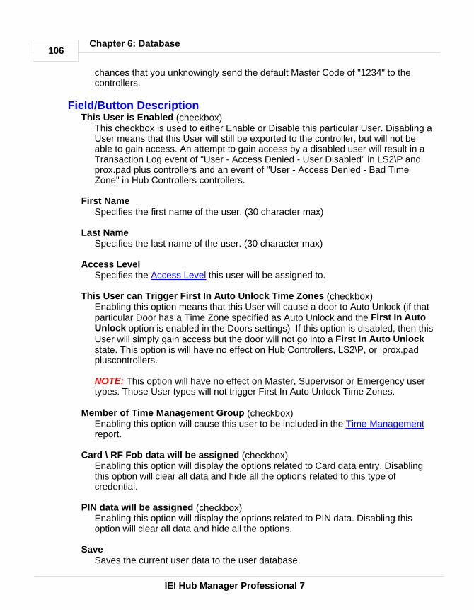
106
IEI Hub Manager Professional 7
Chapter 6: Database
chances that you unknowingly send the default Master Code of "1234" to thecontrollers.
Field/Button DescriptionThis User is Enabled (checkbox)
This checkbox is used to either Enable or Disable this particular User. Disabling aUser means that this User will still be exported to the controller, but will not beable to gain access. An attempt to gain access by a disabled user will result in aTransaction Log event of "User - Access Denied - User Disabled" in LS2\P andprox.pad plus controllers and an event of "User - Access Denied - Bad TimeZone" in Hub Controllers controllers.
First Name Specifies the first name of the user. (30 character max)
Last NameSpecifies the last name of the user. (30 character max)
Access Level Specifies the Access Level this user will be assigned to.
This User can Trigger First In Auto Unlock Time Zones (checkbox)Enabling this option means that this User will cause a door to Auto Unlock (if thatparticular Door has a Time Zone specified as Auto Unlock and the First In AutoUnlock option is enabled in the Doors settings) If this option is disabled, then thisUser will simply gain access but the door will not go into a First In Auto Unlockstate. This option is will have no effect on Hub Controllers, LS2\P, or prox.padpluscontrollers.
NOTE: This option will have no effect on Master, Supervisor or Emergency usertypes. Those User types will not trigger First In Auto Unlock Time Zones.
Member of Time Management Group (checkbox)Enabling this option will cause this user to be included in the Time Managementreport.
Card \ RF Fob data will be assigned (checkbox)Enabling this option will display the options related to Card data entry. Disablingthis option will clear all data and hide all the options related to this type ofcredential.
PIN data will be assigned (checkbox)Enabling this option will display the options related to PIN data. Disabling thisoption will clear all data and hide all the options.
Save Saves the current user data to the user database.

107
IEI Hub Manager Professional 7
Chapter 6: Database
Cancel Discards all edits, and returns you to the user directory
Card FormatNOTE: When adding a new user, you may notice the card format and supportingdata fields may be pre-filled with default data. This occurs because an Operatorwas previously asked if they wanted to set a specific card format to be used as thedefault format for all future user additions, as seen in the following screen shotthat appears when saving the first user added to the system. Directly afterinstallation, no format is set to be the default format yet, so the first user you add,you will need to select a Card format. After that point, if you chose to set thatformat as the default format, it will no longer be necessary to select a card formatwhen adding new users, since it will already be selected for you. This is simply atime saver for you since you will no longer need to select a format, nor will youneed to remember which format to select. Since most systems use the sameformat card for every user added, you will typically need to enter only the cardnumber.
When an HID format is selected, the operator will need to enter the site codebefore this user can be saved. If the operator decides to save this card format andsite code as the new default, then the operator will not need to enter the site codeagain.
Card Format Here you must specify what type of 'card' criteria you will be assigning to this user.The term 'card' is used to represent the type of data entered into this field for thisuser. It can be data of a known HID proximity card format, or the data for an RFFob (radio frequency fob) supplied by IEI. Some card formats explained in thismanual may not be available in all controllers supported by this software. It will bedependant upon the capabilities of the particular controller hardware.

108
IEI Hub Manager Professional 7
Chapter 6: Database
Card Format Name Default Site Code Site Code Editable?IEI 26-Bit 11 YESHID 26-Bit EMPTY YESHID 34-Bit EMPTY YESMagnetic Stripe (ABA Track II) n/a n/aDallas Touch Chip n/a n/aEnrollment Station (HID) n/a n/a
If you have an HID proximity card format that is not shown in the list of cardformats in the software, or you have a custom HID card format, it is possible tohave a custom card format add-on file created by the software vendor and sent toyou. After you install this add-on file on the PC running Hub Manager Professional,you will then have the option of selecting this new format from the 'card format'list, and then be able to enter the card PIN into the program without the need foran Enrollment Station. This does require that you know the exact bit designationsof that particular card format, including all parity bits, card number location andsite code location within the format.
NOTE: If you are using a Motorola Proximity Card reader or Wiegand KeypadFront-Ends with a Secured Series Hub controller, then you will need to select theCard Format named "Magnetic Stripe". And if you are using Motorola Cards, it islikely that you will need to place a "7" in front of the card number that you enterinto the Card Number field.
Visual ID (not required)A text field (50 characters max.) that will allow you to enter the visual identifier ofthe 'card' you are assigning to this user. This is helpful if the card has printing on itthat is not necessarily information related to the data encoded on the credential. Itcan be used as a way to identify the owner of a lost card, if the card is lost andfound.
This field can also be used to store data for any purpose that you wish that isunrelated to the card data, such as entering the employee number, or licensenumber of that user. This could help you to sort the User directory by the dataentered into the Visual ID field.
HID Proximity CardCard Number
This field stores HID proximity card number, typically this is the number printed onthe card, but sometimes the hot stamp is just a reference number and is not thecard number. The length and range of a card PIN will vary based on the particularformat selected
Site Code (if applicable to the selected proximity format)This field will be visible if the card format selected requires the operator to definethe Site Code of the proximity card.

109
IEI Hub Manager Professional 7
Chapter 6: Database
Group Code (if applicable to the selected proximity format)This field will be visible if the card format selected requires the operator to definethe Group Code of the proximity card.
Corp. Code (if applicable to the selected proximity format)This field will be visible if the card format selected requires the operator to definethe Corporate Code of the proximity card.
NOTE: If you know that the Site, Group or Corporate Codes are part of the dataformat you have selected and these fields are not visible, then this format may alsospecify that any or all of these fields are predefined, unchangeable and should not bedisplayed (potentially for security reasons).
Enrollment StationThe enrollment station is a piece of hardware that connects to a serial port of thePC and allows you to read the raw data from an HID proximity card (up to 40 Bit)and then store this raw data in the database and can then be exported to the doorcontroller. This is helpful if you do not know the exact format of the HID proximitycards you are assigning to Users, because with this Enrollment Station option, youdon't have to. The raw data received by the Enrollment Station is the same datathe controller receives and looks up in memory when the controller reads thatsame HID proximity card.
Check with your vendor for information on the availability of the Enrollment Stationequipment.
The steps are simple: 1. Select Enrollment Station as the Card Format.2. Specify the Com Port the Enrollment Station is connected to (if it was not
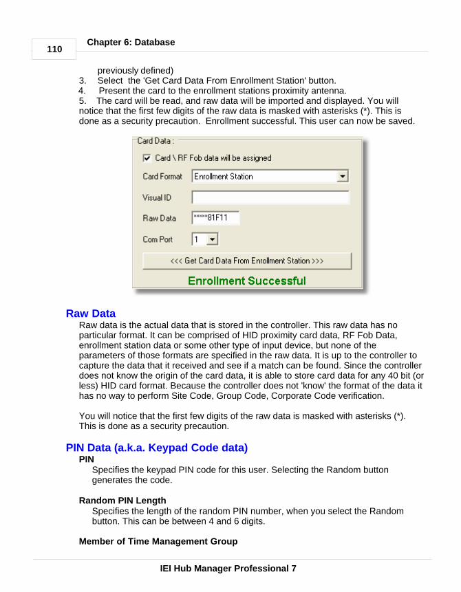
110
IEI Hub Manager Professional 7
Chapter 6: Database
previously defined)3. Select the 'Get Card Data From Enrollment Station' button.4. Present the card to the enrollment stations proximity antenna.5. The card will be read, and raw data will be imported and displayed. You willnotice that the first few digits of the raw data is masked with asterisks (*). This isdone as a security precaution. Enrollment successful. This user can now be saved.
Raw DataRaw data is the actual data that is stored in the controller. This raw data has noparticular format. It can be comprised of HID proximity card data, RF Fob Data,enrollment station data or some other type of input device, but none of theparameters of those formats are specified in the raw data. It is up to the controller tocapture the data that it received and see if a match can be found. Since the controllerdoes not know the origin of the card data, it is able to store card data for any 40 bit (orless) HID card format. Because the controller does not 'know' the format of the data ithas no way to perform Site Code, Group Code, Corporate Code verification.
You will notice that the first few digits of the raw data is masked with asterisks (*).This is done as a security precaution.
PIN Data (a.k.a. Keypad Code data)PIN
Specifies the keypad PIN code for this user. Selecting the Random buttongenerates the code.
Random PIN Length Specifies the length of the random PIN number, when you select the Randombutton. This can be between 4 and 6 digits.
Member of Time Management Group

111
IEI Hub Manager Professional 7
Chapter 6: Database
Lets you assign Time Management status to this user, meaning that this user willbe included in the Time Management Report. Time Management is an entry levelTime + Attendance report. For more information see Time Management.
NOTE: The Time Management Report requires that both 'User IN' and 'User OUT'events must be generated for the report to calculate how long the user was 'IN'the building. Not all controllers generate 'User OUT' events, especially selfcontained locks. Without the OUT events, you would only be able to calculate the'gross' time between the first 'IN' event and the last 'IN' event.
Printing User RecordsSelect Reports > Database from the main menu and then select the Userscheckbox and specify the desired output device.
Master Code · The User List contains, as its first user on the list, the Master Code. This user
has a special function. Its access code is equivalent to the Master Code in acontroller. The factory-default access code for this user is "1234." This code issent to every controller in the system and is placed into user location 1.
· This user is not assigned to an Access Level, because it is not possible to editwhich doors this code will go to.
· Any time a new controller (door) is added to the system, it will automaticallyreceive the "Master Code" when data is exported to this controller.
· This user can be used as a "communications unlock" code, which is requiredfor PDA communications with the LS2\P controllers.
NOTE: The Master Code should normally not be used to gain access to anybattery powered controllers. Using this code type to gain access will reducebattery life, since it unlocks communications and keeps the controller powered upfor up to 60 seconds.

112
IEI Hub Manager Professional 7
Chapter 6: Database
Supervisor Code · The User List contains, as its second user on the list, the Supervisor Code. This
user has a special function. Its access code is equivalent to the SupervisorCode in a controller. The default access code for this user is empty. If youdefine this code in Hub Manager Professional, then this code will be sent toevery controller in the system that supports this user type, and this code isplaced into user location 2 of the controller.
· This user is not assigned to an Access Level, because it is not possible to editwhich doors this code will go to.
· Any time a new controller (door) is added to the system and it supports this usertype, it will automatically receive the "Supervisor Code" when data is exported tothis controller.
· Other user types are described in the Access Level section.· The Profile Series G2 does not support the 'fixed' Supervisor User type, but
instead allows you to assign the Supervisor User type in the Access Leveldefinition. This means you can have any number of Supervisor Users in an Profile Series G2 controller, simply by assigning multiple users to the AccessLevel that is setup with the Supervisor User type (see following image).
Disabling a UserYou may find that you have a user going on an extended vacation or leave ofabsence and you want to disable this user so that their criteria can't be used togain access. Simply edit that user and deselect the checkbox labeled This Useris Enabled, and select Save. Now export to all the doors that this user hasaccess to. When it's time to grant this user access again in the future, simplyselect the This User is Enabled checkbox and export to the controllers again.

113
IEI Hub Manager Professional 7
Chapter 6: Database
Another way to disable a user is to create an Access Levelcalled "NO ACCESS" that has access to no doors in thesystem. Now you can simply move users you want todisable to this particular Access Level, perform all dataexports, which will cause this user to not be grantedaccess. And when the user starts work again, you cansimply change the Access Level for that user to theoriginal Access Level he was assigned to and then exportagain.
If you find that you also want to see events that record that this particular user wastrying to gain access when they should have been on vacation, you can simplycreate an access level that mirrors that access level this user was originallyassigned to, but you will not assign any Time Zones to the doors. Now when thisuser attempts to access the building, an event will be generated and stored in the

114
IEI Hub Manager Professional 7
Chapter 6: Database
controller that says 'Access Denied - Bad Time Zone'.
6.9.1 User List Import Wizard
The User List Import Wizard is a lot like the Add User Group function but with theadded capability to import a user's First Name, Last Name, Keypad PIN, CardNumber, and a Custom text field from a CSV file. This is useful if you have anexisting list of names located in another system such as a Human Resourcespersonnel file, and you wish to save time when adding a large group of userswithout having to type the names of each user that is added to the Hub ManagerProfessional database.
If the user names and data you have are in a third party database system such asa Human Resources database, then review the documentation or help file of thatprogram for information referring to 'Exporting Data to a CSV file'.
This wizard will allow you to import up to 20,000 names from a CSV file.
Required CSV File Format· The CSV name file that you are importing must be in the following format:
Field 1: First NameField 2: Last NameField 3: Keypad PINField 4: Card Number programmed onto cardField 5: Visual ID (typically refers to the hot stamp number printed on an
access card, but can be any text you want to import)· The CSV file shouldn't have a header row.· The CSV file shouldn't have any carriage returns.· If a field such as "Keypad PIN" is being imported, then that field must be filled
for each and every user being imported using the CSV file.· Each field shouldn't be more than 30 characters long. If any field is more than
30 characters, that field will be truncated to the first 30 characters.· Any apostrophes will be removed.· Here is a sample of the required CSV file format:
John,Smith,827163,23862,License Plate - LA-647Jim,Jones,291737,295,License Plate - 28W-E59
Recommended Preparation of the Hub Manager Professionaldatabase before CSV File Import
Although it is possible to import a name list of up to 20,000 and create these userswithout assigning them to an Access Level, it is highly recommended that youassign an Access Level to each of the users you are adding. This will save you avery large amount of time later.

115
IEI Hub Manager Professional 7
Chapter 6: Database
If you are importing 1000's of names and do not assign an access level,afterwards you will have to edit each of these users individually, requiring 1000'sof keystrokes. But this may be the option you want if you prefer to bring in theentire list and then assign the Access Level to the users as you see fit.
The wizard will warn you to not create users without an Access Level assigned.
If you do not know for sure where each and every user will be granted access, youcan always create an empty Access Level that has access to no doors assignedinitially. You can then add the group of people that will most likely have the exactsame access privileges, and modify the Access Levels privileges afterwards.
Try not to add groups of users larger than 1,998 in this manner (1,998 users + 1Master Code + 1 Supervisor Code).
Step 1 - Open CSV FileStep 1 of the wizard prompts you to specify the CSV file where the names arelocated.
1. Select the Open CSV File button and browse to where you have stored theCSV file containing the user names. If the list is Imported successfully you willreceive a message 'File Read OK'.
2. Select Next to continue.
The import function will check for and announce to you any duplicate first and lastname combinations within the CSV file as they are being imported.
Step 2 - Add UsersStep 2 is where the users are actually added to the database
You may select: a block of names, individual names one at a time, or all names inthe list. You may use any combination of these selection tools, but once a name isselected, you can deselect it by removing the check in the checkbox next to thename, or by clicking the 'Uncheck All' button and starting again.
Editing User NamesYou can double-click a user name to edit the First Name or Last Name text.
Selecting a Block of Names by Selecting One from the ListTo select a block of names using the list, first select the name at the top of theblock to be selected, then hold down Shift and select the bottom name of theblock. This will select all names in between the top and bottom names youselected.
Selecting a Block of Names by Specifying the Number of Names to SelectTo select a specified number of names, first select the starting user in the list.

116
IEI Hub Manager Professional 7
Chapter 6: Database
Then enter the number of names you want to select in the edit box labeled 'SelectX Users' (where x is the number you want to select).
Now select the button labeled 'Select X Users'.
The Wizard will now select the specified number of users starting at the top of thelist.
This is useful if you have imported 1,000 names and you only want to select thefirst 300 names, or some subset of names in the middle of the list.
Selecting a Block of Names by Selecting the Individual NamesIf you only have a small number of names to select, you can simply select theindividual names from the list.
Assigning Card Data During the add sequence you may either: auto generate and assign sequentialcard numbers or not assign card data at all. If there was data in the Card data fieldof the CSV file, then that data will be assigned to the user being added.
If you are using the Card data in the CSV file, then you must not specify a startingsequential card number.
Assigning Code PIN Data During the add sequence you may either: auto generate and assign random 4, 5,or 6 digit PIN numbers or not assign PIN data at all. If there was data in theKeypad PIN data field of the CSV file, then that data will be assigned to the userbeing added.
Assigning Visual ID DataIf data is found in the Visual ID field of the CSV file then that data will be usedduring the import process. The Visual ID field is nothing more than a custom textfield and can be used for any data you may have, such as the Hot Stamp of theaccess card, license plate number, employee ID number, etc.
Card FormatsSee Users for an explanation of the different card formats and card format
options available.
Assigning Access LevelsChoose the Access Level you want to add the users to. You can also choose tonot assign the users to an Access Level at this time.
NOTE: If you choose to not assign users to an Access Level, you will need to editeach user individually afterwards.
Adding Users

117
IEI Hub Manager Professional 7
Chapter 6: Database
After you have specified the Card Format, Card data, PIN data, and the AccessLevel to be assigned to the selected users, you can now select the Add button tostart adding these users to the system.
Before attempting to add any users, the wizard will analyze the selected AccessLevel to make sure you are not trying to exceed the capacity of any door assignedto that Access Level. For example: if you have an Access Level named "All Doors"that has access to a controller with a capacity of 2,000 users and 1,800 users arealready assigned to this controller and you attempt to add 700 more users, you willget a warning that the capacity of this door has been exceeded by a certainnumber of users, in this case 500.
Cancel the addition, and go back and edit the list to remove those 500 people thatdo not need access to this particular door. You will have to decide which of these700 users have the greatest priority on getting access to this door. If you requirethat ALL of the 700 people have access, you may be able to upgrade to a doorcontroller that has a higher user capacity if one is available or you may have toexit the Wizard and go back into the main program and go to that door and selectthe 'Capacity' tab and see the breakdown of how users are assigned to this door,and make some changes.
Refer to the Doors section for details.
6.9.2 Add User Group
This feature allows you to add a batch of users with common traits and/orsequential card numbers.
1. Select the Add Group button on the Users screen. The Add Users Groupscreen displays.
2. Enter the information in the add group fields as required.3. Select Add to save the user data to the user database. To cancel the addition
of a card group, select the Cancel button.
NOTE: Before you can start adding new users, Hub Manager Professionalrequires that you edit the PIN of "Master User". This is done to reduce thechances that you unknowingly send the default Master Code of "1234" to thecontrollers.

118
IEI Hub Manager Professional 7
Chapter 6: Database
Field/Button DescriptionNumber of Users to Add
Specifies the number of users being added during this processMember of Time Management Group
Lets you assign Time & Management status to this user.Access Level
Specifies the access level for these users.Generate Sequential Card (checkbox)
Checkbox that specifies that a card credential will be assigned to the users beingadded
Card FormatSpecifies the format of the cards you are adding
First Sequential Card Number Specifies the card number for the first sequential card being added for this group
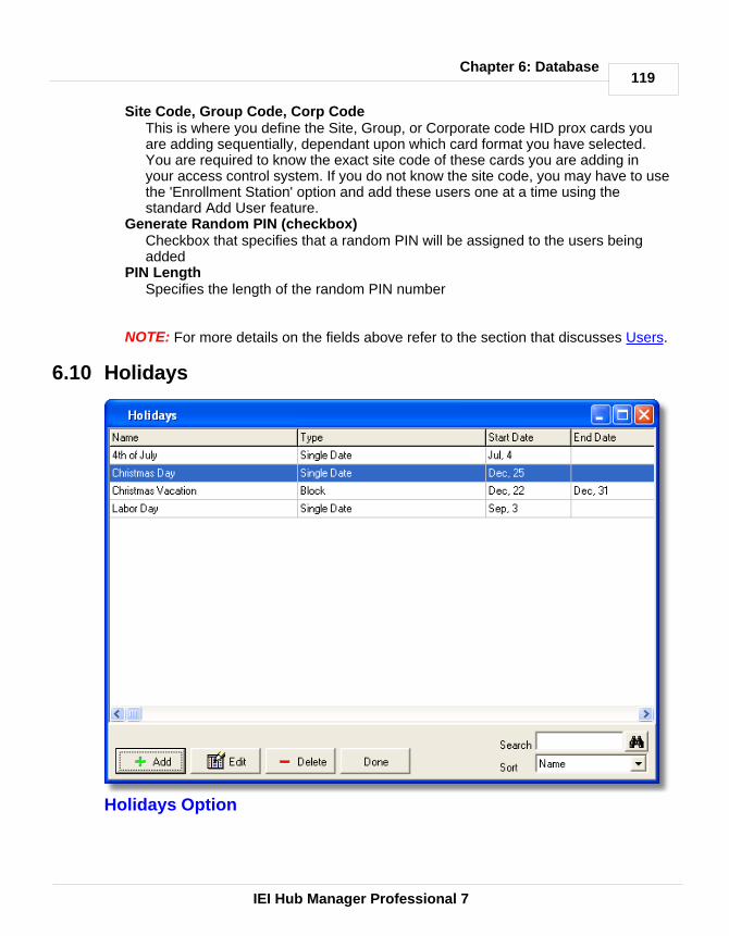
119
IEI Hub Manager Professional 7
Chapter 6: Database
Site Code, Group Code, Corp CodeThis is where you define the Site, Group, or Corporate code HID prox cards youare adding sequentially, dependant upon which card format you have selected.You are required to know the exact site code of these cards you are adding inyour access control system. If you do not know the site code, you may have to usethe 'Enrollment Station' option and add these users one at a time using thestandard Add User feature.
Generate Random PIN (checkbox)Checkbox that specifies that a random PIN will be assigned to the users beingadded
PIN Length Specifies the length of the random PIN number
NOTE: For more details on the fields above refer to the section that discusses Users.
6.10 Holidays
Holidays Option
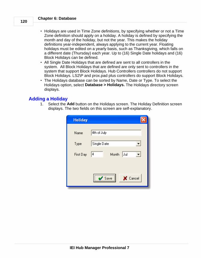
120
IEI Hub Manager Professional 7
Chapter 6: Database
· Holidays are used in Time Zone definitions, by specifying whether or not a TimeZone definition should apply on a holiday. A holiday is defined by specifying themonth and day of the holiday, but not the year. This makes the holidaydefinitions year-independent, always applying to the current year. Floatingholidays must be edited on a yearly basis, such as Thanksgiving, which falls ona different date (Thursday) each year. Up to (16) Single Date holidays and (16)Block Holidays can be defined.
· All Single Date Holidays that are defined are sent to all controllers in thesystem. All Block Holidays that are defined are only sent to controllers in thesystem that support Block Holidays. Hub Controllers controllers do not supportBlock Holidays. LS2\P and prox.pad plus controllers do support Block Holidays.
· The Holidays database can be sorted by Name, Date or Type. To select theHolidays option, select Database > Holidays. The Holidays directory screendisplays.
Adding a Holiday1. Select the Add button on the Holidays screen. The Holiday Definition screen
displays. The two fields on this screen are self-explanatory.

121
IEI Hub Manager Professional 7
Chapter 6: Database
2. To define a holiday, select an undefined holiday and type in the name for it, inthe "Name" field.
3. Select the desired "Type." For Single day start, enter the first day and monthfields; for Block, enter both the first day and month and the last day andmonth. Because year information is not specified, the start date has toprecede the end date in the single calendar year.
4. Select Save to save the holiday definition.
Printing HolidaysSelect Reports > Database from the main menu and then select the Holidayscheckbox and specify the desired output device.

122
IEI Hub Manager Professional 7
Chapter 7: Communications
Chapter 7: Communications
7.1 Security Chip
A "Security Chip" is a small microchip that must be installed into the controller thathas a Controller Address of 1 in Hub Controllers hardware networks so thatexporting and/or importing from the PC software can be performed. Eachseparate network of Hub Controllers controllers must have a controller with anaddress of "1" and that controller must contain a security chip.
Those controller types that require a security chip are: HC500, Hub+\Max, MaxIIv1 and MaxII v2.
7.2 Communications Menu
The Communications menu contains most of the options that allow you to senddata to a controller or import data from a controller.
Select Communications from the main menu. The Communications drop-downmenu displays.Import Door SettingsImport\Export DoorsNetwork Query
7.3 Import Door Settings
NOTE: The Import Door Settings can not be performed on PDA connectedcontrollers.
The Import Door Settings option imports and displays the complete user data and door settings of any physically connected (com port, modem, or TCP/IP) doorcontroller to the Hub Manager Professional computer. This is useful if the contentswere modified from the local keypad, or in case of unknown diagnostic problemswith a controller. You can then view, print, or save this information to a .CSV file.This imported information is stored separately from the central Hub ManagerProfessional databases in a text file, and cannot overwrite any data in thedatabase.
1. Ensure that the desired site is connected and then select Communications >Import Door Settings from the Hub Manager Professional main menu toaccess the Import Door Settings option.
2. Select the door controller you wish to import the settings from. To begin theimport, select Import. The program displays the progress of the import at thebottom left of the screen.
3. To print, view, or save the door configuration import information, select Printand then select your choice of output device. If you select File, you must enter

123
IEI Hub Manager Professional 7
Chapter 7: Communications
a name for the file in the "Filename" box.
7.4 Import\Export Doors
The Import\Export Doors option on the Communications menu lets you send andreceive data to and combination of doors without the need for you to manually"connect" to each individual site. During the export process, each site willautomatically be connected to and the communication to the selected doors will beattempted.
1. Select Communications > Import\Export Doors from the main menu.2. Any doors that are known by the database to contain changes will
automatically will already have a checkmark next to the door name. If nodoors are selected when this screen is opened, then this means that HubManager Professional believes that all changes were sent to the controllers ina previous export.
3. Make any additional door selections (if required).4. Select the Start button to begin the communications process.
NOTE: For PDA connected sites, make sure that after an export is complete yourun HotSync. This will move the data files from the PC to the PDA.

124
IEI Hub Manager Professional 7
Chapter 7: Communications
Field/Button DescriptionWorking (Progress Bar)
Shows detailed progress for the current door
Door (Progress Bar)Shows the progress of the individual door currently being communicated with.
Total (Progress Bar)Shows the total progress for all selected doors
Update Time/Date (checkbox)If this option is enabled, then the current time and date of the PC will be sent tothe selected controllers. If you have a PDA connected controller, then this optionwill have no effect, since that controller type will get it's clock update from the PDAitself.
NOTE: With the LS2\Pand MaxII v2 controllers, there is no need to update thenew time and date when Daylight savings takes place. The time in the doorcontroller will automatically change, as long as the 'Daylight Savings Time' optionis enabled in the Door options screen for those particular doors.
Import Transaction Log (checkbox)If this option is enabled, then the Transaction Log of the selected Door controllerswill be imported and placed into the Hub Manager Professional database.
Export Changes Only (checkbox)If this option is enabled, then just changes since the last successful export will besent to the selected Door controllers. Enabling this option results in a faster exporttime.
Export ALL the data (Full Export) (checkbox)If this option is enabled, this will result in the longest possible export time, but thiswill guarantee that all data in the Door controller will be overwritten and will matchthe data in the software exactly.
NOTE: If you have replaced the controller hardware for a particular door, or if youhave erased (defaulted) the memory of a controller, it is required that you enablethis option and only select those doors that had a controller replaced or weredefaulted, then perform an export. This will result in all data in the controller beingcompletely synchronized with the database on the PC.
Door Selection List (checkboxes)Placing a checkmark next to a door name will include that door in thecommunication process. If a door already has a checkmark next to it when youenter this screen, this means that changes have been made to the data containedin that door since the last successful export. For this reason, it is typically notnecessary for you to select the doors to export to, since the program will

125
IEI Hub Manager Professional 7
Chapter 7: Communications
automatically select for you the doors that are known to contain changes. Uponentering the Import\Export Doors screen, you typically only need to select the Startbutton to start the export process, unless there are other functions you would liketo perform.
Select All Doors Selects all doors in the door selection list
Select No DoorsDeselects all doors in the door selection list
Start\StopStarts\Stops the export process
DoneCloses the Import\Export Doors screen and returns you to the main screen
7.5 Network Query
NOTE: If the site you are trying to Network Query are PDA connected controllers,then the program will simply look for the most recent event in the transaction logand will display that time and date. This is helpful if you want to know the last timethe PDA connected controller was communicated with.
The Network Query option scans the controller addresses of the currentlyconnected site and displays the online\offline status of the controllers. After theoption is activated, the program searches the network of controllers for each"Controller Address" starting at door 1 and incrementing each time.
NOTE: If you want to query just a single door, go Database > Doors, open thatdoor for editing and select the 'Query Now' button.
1. Select Communications > Network Query from the Hub Manager Professionalmain menu to access the Network Query option. The initial Network Queryscreen displays.
2. Place a checkmark in the "Add new found doors" box to specify that if theprogram finds any new controllers that are not currently in the system, theprogram will add these new controllers to the system. Each time the programfinds a new door controller, it prompts you with a door settings screen to confirmthe name and door settings being assigned before adding it to the Doorsdatabase.
3. Press Start to begin the network scan.4. The program polls each of the networked door controllers on the site. Each
controller's network status starts with a Blue Question Mark in each doorlocation, which indicates an UNTESTED location. As the operation continuesand each door controller location is polled, the Door Status is reflected by anicon that represents one of the device types.

126
IEI Hub Manager Professional 7
Chapter 7: Communications
Network Query Process 1. Start the Hub Manager Professional program.2. Select Database > Sites. The Sites window displays.3. Select the site to which you wish to connect and then select the Connect button.4. After the connection is made, select the Cancel button.5. Select Communications > Network Query from the Hub Manager Professional
main menu to access the Network Query option. The initial Network Querywindow displays.
6. Press Start to begin the network scan.
Field/Button DescriptionCurrent Site
Identifies the current site being tested.Add new found doors box
Selecting this box directs that, if the program finds any new, unexpectedcontrollers, Hub Manager Professional is to add these new controllers to thesystem.
Start\StopStarts\Stops the network query of the currently connected site.
DoneCloses the Network Query screen, and returns to the main screen.
Found, Name, Expected Displays the network status of the controllers.
Description of Network Query IconsBlack Checkmark
Controller event data was foundRed "X"
No door controller event data was foundBlue Question Mark
UNTESTED door location
The software only queries the site to which you are currently connected; itattempts to query the maximum doors permitted at any site, one at a time.

127
IEI Hub Manager Professional 7
Chapter 8: Tools
Chapter 8: Tools
8.1 Tools Menu
Select Tools from the Hub Manager Professional main menu. The Toolsdrop-down menu displays.Log ArchivingAudit ArchivingDatabase Backup/RestoreDatabase Conversion UtilityRun Com Port TestExternal ToolsScheduled Log ImportTable InitializationIndexingApplication InitializationOptions
8.2 Log Archiving
The Log Archiving option moves the transaction log from the working directory tothe default archive directory. You should run this when you no longer need to filterthe data stored in the current log database, or if you wish to move it to a .CSV file.
1. Select Tools > Log Archiving from the Hub Manager Professionalmain menuto access the Log Archiving option. The Log Archive screen displays.
2. Decide if you wish to change the default folder or file name for the log archive.The default folder is "Archive and the default file name is "Log" followed bytoday's date. If so, select the Change button. An 'Open Folder' navigationscreen displays, initially showing the default directory to which the log archive is

128
IEI Hub Manager Professional 7
Chapter 8: Tools
to be backed up.3. Highlight the desired log archive file you wish to archive; next, if the default
directory or file name is not correct, navigate to the desired directory usingstandard Windows techniques, and/or change the file name, and then selectthe Open button. You return to the Log Archive screen.
4. Select the Archive Now button. A message displays informing you of the statusof the archive.
Log Archives can be opened later using the Reports > Archive Viewer option,but once a Log is archived it can no longer be filtered in Hub ManagerProfessional.
8.3 Audit Archiving
The Audit Archiving option permits you to archive (move) the Hub ManagerProfessional Audit file from the default directory to a directory and filename youspecify; the archive file is stored in .CSV format. An Audit file records whichactions the operator performed using the Hub Manager Professional software.
1. Select Tools > Audit Archiving from the Hub Manager Professional mainmenu to access the Audit Archiving option. The Audit Archive screen displays.
2. Decide if you wish to change the default folder or file name for the auditarchive. The default folder is "Archive" and the default file name is "Audit"followed by today's date. If so, select the Change button. An 'Open Folder'navigation screen displays, initially showing the default directory to which theaudit archive is to be archived.
3. Highlight the desired audit archive file you wish to archive; next, if the defaultdirectory or file name is not correct, navigate to the desired directory usingstandard Windows techniques, and/or change the file name, and then selectthe Open button. You return to the Audit Log Archive screen.
4. Select the Archive Now button. A message displays informing you of thestatus of the archive. Audit archives can be opened for viewing using the Reports > Archive Viewer option.

129
IEI Hub Manager Professional 7
Chapter 8: Tools
8.4 Database Backup/Restore
The Database Backup/Restore option permits you to backup (copy) the HubManager Professional databases from the default database directory to the\backup directory. The Restore button in this option, in contrast, lets you restorethe backed up Hub Manager Professional databases from the \backup directory tothe default database directory, which overwrites (and deletes) the current HubManager Professional databases.
1. Select Tools > Database Backup/Restore from the Hub ManagerProfessional main menu to access the Database Backup/Restore option. TheDatabase/Restore screen displays.
2. Select the Backup button to begin the backup. Alternatively, select theRestore button to begin the restore. The program displays messages to keepyou informed of the status of the backup or restore.
NOTE: If you attempt to restore a database backup created from a database priorto Hub Manager Professional 7, or from any other incompatible source, theprogram will instruct you to perform the data conversion (check with your softwarevendor for data conversion utility availability).

130
IEI Hub Manager Professional 7
Chapter 8: Tools
8.5 Database Conversion Utility
WARNING: Performing this data migration function will overwrite anyexisting data you may have stored in Hub Manager Professional 7. Ifyou have any data in Hub Manager Professional 7 that you need to save,perform the "Backup" function under the Tools menu, and select afolder that is outside the Hub Manager Professional 7 folder structure.
A utility is provided to allow you to migrate an existing Hub Manager Professionaldatabase into Hub Manager Professional 7. This utility is located in the followingfolder:C:\Program Files\IEI\HubManagerPro7\Program\Conversion.exe
You may launch the utility by inserting the CD ROM (or running the filedownloaded from the web) and choosing the Conversion option. The HubManager Professional 7software must be installed on that PC before running theconversion option from the CD.
You may launch the utility by using the shortcut located at: Start > Programs > Hub Manager Professional 7 > Conversion Utility
1. Run the Conversion.exe utility any location noted above.2. If you are running from the desktop (Main PC) then double click the following
in this order:'My Computer' icon on the desktop

131
IEI Hub Manager Professional 7
Chapter 8: Tools
Local Disk C:'Program Files' folder'IEI' folder'HubManagerPro7' folder'Program' folderConversion.exe file
3. A screen will appear (see image below) that allows you to select whichsource data you would like to migrate from, and also which product that thedata will be migrated into. The options in the "Source" drop down list let youspecify which databases can be used as a source database, and the optionsin the "Destination" drop down list specify what Hub Manager Professionaldatabase will receive the converted data.
4. Hub Manager Professional source data is not modified in any way; it is merely

132
IEI Hub Manager Professional 7
Chapter 8: Tools
copied and re-formatted appropriately into the destination database. 5. At the end of the data migration, run the destination Hub Manager
Professional 7 program and run the Import\Export Doors option with theExport ALL the data option enabled, and have selected all the doors, inorder to properly synchronize the software and hardware.
6. Do not perform a transaction log import until you have successfully performedan export to all the doors.
Converting a Database From a Custom FolderThere is an option to let you browse to a custom Source folder andconvert/migrate that Hub Manager Professional database into the destinationfolder. This is useful if you are installing a newer version of Hub ManagerProfessional on a new PC and you want to migrate data from an older version ofHub Manager Professional that you copied from an older PC to a folder on thisnew PC. 1. You first specify which version of Hub Manager Professionaldatabase source
you are converting by selecting the database type from the 'Source' dropdown list.
2. You then select the check box labeled 'Let me specify the source folder'. 3. You then browse to the folder where those database files are located. 4. You then select the Destination Hub Manager Professionaldatabase you are
converting to.5. Finally select the 'Convert Now' button to start the conversion process.
Converting a data when you are using System ManagerIf you used System Manager to create multiple systems, then you must followthese instructions in order to convert the databases of those Systems.
1. Use System Manager that came with Hub Manager Professional 7 to createone NEW System for each of the prior version Systems you want to convert to Hub Manager Professional 7. These new systems can be created in the sameSystem Repository folder you used, but you will need to use a new name for thesystem. Placing a " 7 " at the end of the new System name will help you toidentify the old and new systems more easily.
2. Open Hub Manager Professional 6 and open the system you want to convert.Now open Hub Manager Professional 7 and open one of the NEW systemsyou want to convert the old data into.
3. Now launch the Conversion utility by going to Tools > Database ConversionUtility in Hub Manager Professional 7.
4. Make sure the Source and Destination selections are correct and selectConvert Now.
5. Repeat Steps 2-4 as needed.

133
IEI Hub Manager Professional 7
Chapter 8: Tools
8.6 Run Com Port Test
NOTE: If you are using PDA connected controllers, it will not be necessary toperform the Com Port Test.
About the Com Port Test ProgramThe Run Com Port Test option, once selected, runs a standard Com Port test.This program tests the availability of your computer's Com ports 1 - 4, and alsodetermines if these ports can be used for communications via the suppliedconnectors.
You can run it as necessary from the Tools menu, and can specify a differentdirectory in which to store the Com test program using the Tools > ExternalTools option.
The name and path of the program that is run when the Run Com Port Test itemis selected from the Tools menu can be modified using the Tools > ExternalTools form. See External Tools
Running the Com Port Test 1. This program tests the availability of your computer's Com ports (serial
communications ports), and also determines if these ports can be used forcommunications via the supplied connectors. IEI recommends that you runthis program; it can also be selected and run separately. There are two partsto this procedure (testing without the loopback connector and testing with it),and both parts must be performed.
2. Start the COM Test program in one of two ways: (a) by selecting Finish on theSetup Complete screen at the end of the Install program, or (b) from the HubManager Professional Main Menu, Tools > Run Com Port Test. The"Launching Com Port Test" message displays followed by the Initial COMPort Test screen.
3. To start the first part of the Com test, disconnect all devices from the Comport on your computer designated for Hub Manager Professional controllercommunications, then select Start Test.
4. This message then displays: Please make sure the loopback connector isNOT installed and select OK to continue or CANCEL to stop testing.
5. Ensure that the supplied Loopback connector is Not connected to any of theCom ports on your computer. Then select OK. The program conducts the firstpart of the Com test by looking for all available Com ports. A message thendisplays, indicating part one is over.
6. Please connect the loopback connector to your computer's COM port. 7. Select OK to continue or cancel to stop testing. 8. Connect the Loopback connector to the computer Com port designated for
Hub Manager Professional controller communications. One side of theLoopback connector has a female DB9-pin connector, the other side aDB25-pin connector; connect using the appropriate side, then select OK, tobegin the second part of the Com test. If part two of the Com test is

134
IEI Hub Manager Professional 7
Chapter 8: Tools
successful, this or a similar message displays overlayed on the Test Resultsscreen.
9. The test connector has been found at COM Port: x. Please record thisinformation and select the same COM port for use with the Hub ManagerProfessional program.
10. If the test is not successful, there can be several problems: no Com ports areavailable, available Com ports are being shared with other devices, oravailable Com ports are not working correctly. Contact your computer dealeras you may need to add another Com port.
11. Record the Com port information safely as instructed and then select OK. 12. Review the information on the Com Port Test Results screen as necessary
and then select Close.
8.7 External Tools
The External Tools option permits you to specify the directory and file to use forthe Com Port Test program, in the case where you want to use a different ComPort Test Program. The path to the com port test supplied with Hub ManagerProfessional is already defined.
1. Select Tools > External Tools from the Hub Manager Professionalmainmenu to access the External Tools program settings. The External Toolsscreen displays, showing the default path and parameters.
2. Enter the desired path and parameters, if the defaults are not correct andselect the Save button.
To navigate to a different path, select the Find button and then use standardWindows navigation techniques to specify the desired path on the Open screen(not shown). The Com Port Test program is located in the Hub ManagerProfessional 7folder in the \program folder at the following path: C:\Program Files\IEI \HubManagerPro7\Program\COM TEST.exe
These settings do not normally need to be changed.
See also: Run Com Port Test
8.8 Scheduled Log Import
The Scheduled Log Import option lets you specify the time of day the import willbe performed, the number of days between the automatic imports, and start dateparameters. The automatic importing of the Transaction Log data will beperformed on all door controllers in all sites.
NOTE: You must log out from but NOT exit the Hub Manager Professionalprogram for the automatic importing of transaction logs to occur. If an operator islogged in when the scheduled import is set to start, then a prompt displays askingthe Operator if the import should be performed. The Operator must select YES for

135
IEI Hub Manager Professional 7
Chapter 8: Tools
the import to be performed, otherwise the import will not start.
NOTE: The delay period is how many days you want to lapse before anotherscheduled log import will occur.
NOTE: With PDA connected controllers such as the LS2\P, the Scheduled LogImport feature will simply attempt to import any new Transaction Log data thatmay have already been placed onto the PC during a HotSync with a PDA running LS Link. This can be helpful if you have a person, such as a tour guard, that isresponsible for regularly visiting the door controllers with the PDA and collectingthe Transaction Logs, and only HotSync's the PDA with the managers PC andleaves. With Scheduled Log Import enabled, Hub Manager Professional willautomatically import those new transaction events into the database, without theneed for the manager to remember to perform that action before generating aTransaction Log report. This helps keep newly generated reports, that themanager creates, as up to date as possible.
1. Select Tools > Scheduled Log Import from the Hub Manager Professionalmain menu to access the Scheduled Log Import program. The ScheduledLog Import screen displays.
2. Enable the 'Use scheduled log import' checkbox to enable this feature.3. Enter the desired parameters and select the OK button.
See also : Logout, Scheduled Log Import Errors, Scheduled Log Import Reminder

136
IEI Hub Manager Professional 7
Chapter 8: Tools
8.9 Scheduled Log Import Reminder
See also Scheduled Log Import
If you are logged into Hub Manager Professional when the Scheduled Log Importis set to run automatically, a message box will appear asking you if you want torun the import now.
If you had intended for the scheduled log import to run automatically without anyuser intervention, you must log out of Hub Manager Professional using theSystem > Logout menu command.
Forcing you to logout is done as a safety precaution so that the software can beleft running and set to import logs automatically, but not be left in a vulnerable"logged in" state where someone may be able to see sensitive information such asaccess codes.
8.10 Table Initialization
WARNING: THIS PROCEDURE RESULTS IN UNRECOVERABLE DATALOSS!!! The Table Initialization option initializes (resets to zero) the Hub ManagerProfessional program's databases. You can select from several types ofinitialization: Database - all operator entered data, including all users and door settingsTransaction Log - just the transaction log dataAudit Trail - just the operator audit trail
1. Select Tools > Table Initialization from the Hub Manager Professionalmain menu to access the Table Initialization program. The Initialization ofDatabases screen displays.
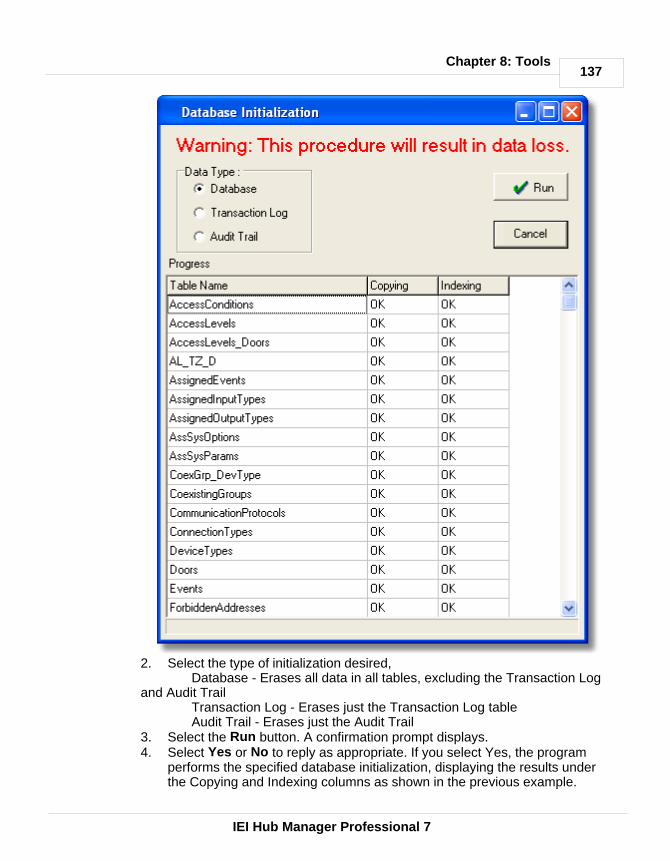
137
IEI Hub Manager Professional 7
Chapter 8: Tools
2. Select the type of initialization desired, Database - Erases all data in all tables, excluding the Transaction Log
and Audit TrailTransaction Log - Erases just the Transaction Log tableAudit Trail - Erases just the Audit Trail
3. Select the Run button. A confirmation prompt displays.4. Select Yes or No to reply as appropriate. If you select Yes, the program
performs the specified database initialization, displaying the results underthe Copying and Indexing columns as shown in the previous example.

138
IEI Hub Manager Professional 7
Chapter 8: Tools
8.11 Application Initialization
The Application Initialization option defaults the program's parameters back to an"Out of Box" state. Using this option in conjunction with the "Total DatabaseInitialization mode returns all databases and programs settings to the default "OutOf Box" settings. It would be the equivalent of deleting all databases andreinstalling the Hub Manager Professional software.
The parameters and settings that are reset include, but are not limited to:· disables the "Scheduled Log Import" feature and settings· disables System Manager and associated settings· defaults the Report Writer path, password, and options· disables Auto Login· removes custom Support contact info· removes the default card format setting· removes all memory of custom screen size and position of the screens opened
in Hub Manager Professional
1. Select Tools > Application Initialization from the Hub ManagerProfessional main menu to access the Application Initialization program. Aconfirmation prompt displays.
2. Select OK or Cancel to reply as appropriate. If you select OK, the programresets all application settings to the default values and then displays a promptat the end (not shown).
3. Select OK.
8.12 Indexing
The Indexing option indexes the Hub Manager Professional program's databases.Indexing reorganizes all the records in each database so that user access is fasterand more efficient. Running this option is not usually necessary. No data ismodified during this process.
1. Select Tools > Indexing from the Hub Manager Professional main menu toaccess the Indexing program. The Indexing screen displays.
2. Select the Run button to continue indexing or the Cancel button to return tothe main menu. A confirmation prompt displays. If you select Run, theprogram performs the indexing, displaying the results under the right hand"Results" column.
3. Select the Cancel button to return to the main menu.
NOTE: If you ever receive an Indexing error within Hub Manager Professional,perform the Indexing option to resolve.

139
IEI Hub Manager Professional 7
Chapter 8: Tools
8.13 Options
Report WriterThese options regard the creation of the Report Writer database.
The 'Report Writer Database Copy' feature creates an exact copy of the currentdatabase that Hub Manager Professional is working from. The copy is made inorder to allow a 3rd party report writing program such as Crystal Reports toaccess the data for the purpose of creating custom reports. This allows the Hub

140
IEI Hub Manager Professional 7
Chapter 8: Tools
Manager Professional database to maintain data integrity, by not allowing accessto the actual data, and at the same time, give the data to an outside source.
Report Writer Database Path This is where the database copy will be stored.
Report Writer Database PasswordThis is the password that will be required to open the database copy within the 3rdparty report writer.
Auto-Update OptionsSpecifies when the database copy will be updated. Selecting all 3 will keep thedatabase copy up to date.
Silent Report Database Copy Enabling this option stops any messages from prompting the operator to selectOK or Cancel to the copying procedure.

141
IEI Hub Manager Professional 7
Chapter 8: Tools
System ManagerSee section System Manager for a detailed description of the System Manageroptions
Backup AlertThe Backup Alert is a feature that will prompt you to perform a backup of the dataif you have not performed a backup in the time period that you specify. Thebackup alert will occur at the time you log into a system. If on a given day, youchoose to decline backing up, you will not receive any more prompts that day, butyou will receive the backup alert prompt each time you log into that particularsystem on each subsequent day until a backup is performed.
The delay period can be set from 1 - 365 days.

142
IEI Hub Manager Professional 7
Chapter 8: Tools
General OptionsAuto Login
Enabling this option will cause the program to automatically attempt to log you inusing a name and password you specify, whenever the login is displayed.
NOTE: This option should only be used if you are not worried that an unauthorizedperson will sit at your computer and attempt to access the Hub ManagerProfessional database and access codes. If you think there is a chance of this,then this option should be disabled immediately.
Show Splash screen at program startupDisabling this option not show the splash screen when the program is launched,thereby creating a slightly faster startup.
Continue displaying the System Startup Tasklist even when all items arecompleted
Enabling this option will cause the cause the Tasklist to always remain visible,even when completed.

143
IEI Hub Manager Professional 7
Chapter 8: Tools

144
IEI Hub Manager Professional 7
Chapter 9: Reports
Chapter 9: Reports
9.1 Reports Menu
Select Reports from the Hub Manager Professional menu. The Reportsdrop-down menu displays.
Once you select the specific type of report, the software displays prompts toengage you in the print reports dialog. The first prompt requests that you specifythe information you wish to see in the report, the second lets you specify theoutput device. You can print reports to the Monitor (screen), the Printer, or a File;if you select File, you must enter a name for the file in the "Filename" field. Youdirect the software to print the report by selecting the Print button.
see also:
Log FilterTime ManagementMisc. Log ReportsAssignment ReportsDatabase PrintingAudit ReportArchive ViewerGenerate Report Writer DatabaseScheduled Log Import Errors
9.2 Log Filter
The Log Filter reports contains details of the transaction logs from the controllersconnected to the system. You can modify the contents by selecting differentparameters.
Only those events that are supported by the selected door types will be displayedon the right.
1. Select Reports > Log Filter from the Hub Manager Professionalmain menu.The Filtered Log screen displays (see the following screen shot).

145
IEI Hub Manager Professional 7
Chapter 9: Reports
2. Specify the information to appear on the report on the Filtered Log screen.Enter the Users to be included in the report, specify the "From" and "To" daterange, select the door to be included in the report; and check the desiredevents on the right-hand side (or use the "All" buttons). Only the events thatmatch al the criteria will be displayed in the report.
3. Specify the desired output device for the report (on the bottom left of thescreen): Monitor (screen), Printer, or File; if you select File, you must enter aname for the file in the "Filename" field. "Monitor" is the default choice. Selectthe Print button to print the report.

146
IEI Hub Manager Professional 7
Chapter 9: Reports
NOTE: The Log Filter report is best printed in landscape format so that all the datain all columns will fit.
No date filteringEnabling this option will cause the report to disregard any date filter you may haveentered. This will allow you to see the entire contents of the transaction log, andcan be helpful if events were imported with wrong time\date data that may haveaccidentally been outside the range of the date range criteria, and thereforecausing those events to not be displayed in the report. The report will be sorted bydate and time.
No filtering at all, display the entire log

147
IEI Hub Manager Professional 7
Chapter 9: Reports
Enabling this option will cause the report to disregard any filter you may haveentered, including users, access levels, doors, events, or date range. This willallow you to see the entire contents of the transaction log, and can be helpful ifevents were imported with data that may have accidentally been outside the rangeof the filter criteria. The report will be sorted by date and time.
First Record \ Last RecordThese buttons will search the Log Table for the oldest or newest events and setthe From and To filters to those respective dates.
If the operator selects the 'First Record' or 'Last Record' buttons and there are norecords in the Log table at all then a message will be displayed 'There are norecords in the log table to sort. You must import a log first.'
"Unknown User ID"There is an event that may appear in your Log Filter Report that says 'UnknownUser ID: X' (where X is a user location reference). There are a few reasons thatthis event will be generated by Hub Manager Professional.
1. Regardless of the controller type, this event will be generated if someonewere to go into programming mode manually at the controller and try to add auser code for the purpose of 'hiding' it because they are trying to breach thesecurity system. The reference number that is assigned to this event in thiscase will be the user location that the code was assigned to during manualprogramming. For example if someone tried to hide a code in user location2000 of the controller, if someone attempted to use this user code to gainaccess, after the log was imported, an event would be displayed as 'UnknownUser ID: 2000 Access Granted - IN'. If you see this 'Unknown User' eventand your system has been up and running for some time, and you know youhave imported logs from this door previously, then the chances are good thatsomeone has manually programmed a user into the controller. To removethis user, you should perform a full export to this controller, by enabling the Export ALL the data checkbox in the Import\Export Doors screen.
2. Regardless of the controller type, any user generated events that occurredbefore Hub Manager Professional had exported user data to this controllerwill cause 'Unknown User ID' events to occur. This is because all usercreated events of these device types are tagged with an ID of the user thatwas used to trigger that event. When Hub Manager Professional exports userdata to the controllers, it assigns a unique 'User ID' that it knows and is notpresent on new or defaulted controllers. If you see one of these 'UnknownUser ID' events during your initial Log Import from either of these devicetypes, you can dismiss it. Because these events occurred before the programand controller were synchronized. If you have already exported to thiscontroller, then any subsequent Log Imports will not generate this 'UnknownUser ID' event, except for the other reasons that this event may be generatedas noted in this section.

148
IEI Hub Manager Professional 7
Chapter 9: Reports
3. This 'Unknown User ID' can also occur if you were to install a controller thathad previous transaction log event data in the controllers event buffermemory. To stop this event from occurring on newly installed controllers,whether it be new or used, erase all system data as well as defaulting the logdata. The programming commands for most of your controllers would be toenter programming mode and enter 46# 00000# 00000# * * to delete systemdata and also 76# 00000# 00000# * * to delete transaction log data. Alwaysrefer to the programming manual that came with the controller for thecommands.
9.3 Time Management
NOTE: The Time Management Report requires controllers that can record both'User IN' and 'User OUT' events. All controllers can generate 'User IN' events butnot all controllers can generate an 'OUT' event, especially self contained locks. Tofind if a specific controller can generate an 'OUT' event, go to the 'Options' tab ofthe door settings screen, and look in the 'Log Events' list for an entry labeled 'User- Access Granted OUT'. If this entry can not be found, then this particularcontroller type can not be set to record 'OUT' events.
The Time Management report prints details of the transaction logs from thecontrollers managed by the system. You can modify the contents by selectingdifferent parameters.
This report calculates how long a user was "IN" on a particular day. It gives boththe "gross time" and the "clear time."
'Gross Time' is the time between the first and last recorded events of that singleday. This feature is not designed to work with 3rd Shift Workers that cross overthe midnight boundary.
'Clear time' is the gross time minus the time that the user clocked out for breaks.A requirement for calculating 'clear time' is that users must come "IN" on acontroller set to Log as "IN" and users must exit using a controller set to "OUT",then enter again using a controller set to record as "IN", in that order. If theprogram does not see an opposing "IN" or "OUT" event for that user, anappropriate error will be printed on the report for that day, such as the term"Missing" in the 'OUT' event column, and the clear time calculation will not becalculated properly.
1. Select Reports > Time Management from the main menu. The TimeManagement screen displays.
2. Specify the desired "User Selection" choice, the desired "Date Range," selectthe desired doors, and select "Print To" output device for the report: Monitor(screen), Printer, or File. If you select File, you must enter a name for the filein the "File name" field. "Monitor" is the default choice. Select the Print buttonto print the report.

149
IEI Hub Manager Professional 7
Chapter 9: Reports
9.4 Misc. Log Reports
The Misc. Log Reports can show:· the first and last event that occurred each day· what days a particular User was granted access· who was granted access on a particular day
1. Select Reports > Misc. Log Reports from the Hub Manager Professionalmain menu. If data is present, the Misc. Log Reports screen displays.
2. Specify the information to appear on the report on the Misc. Log Reportsscreen. Enter your "User Selection" choice, the appropriate "Date Range,""Report Type," and the "Print To" output device for the report: Monitor(screen), Printer, or File. If you select File, you must enter a name for the filein the "Filename" field. "Monitor" is the default choice.
3. Select the Print button to print the report.

150
IEI Hub Manager Professional 7
Chapter 9: Reports
9.5 Assignment Reports
The Assignment Reports screen allows you to select from 4 different report types.Each report type allows you to select the individual items that you want to includein the report. Report types include:· Show the Access Levels that contain select doors· Show the Users assigned to each door· Show the Doors each User can access· Show the Users assigned to each Access Level
To use this reporting tool, perform the following:1. Select Reports > Assignment Reports from the Hub Manager Professional
main menu to show the Assignment Report selection screen.2. In the section of the screen labeled "Report Types", select which report type
you want to generate.3. Select the items you want to include in the report. Options that are specific to
that report type are discussed in the following sections that describe theindividual report types.
4. Specify the "Print To" output device for this report: Monitor (screen), Printer,
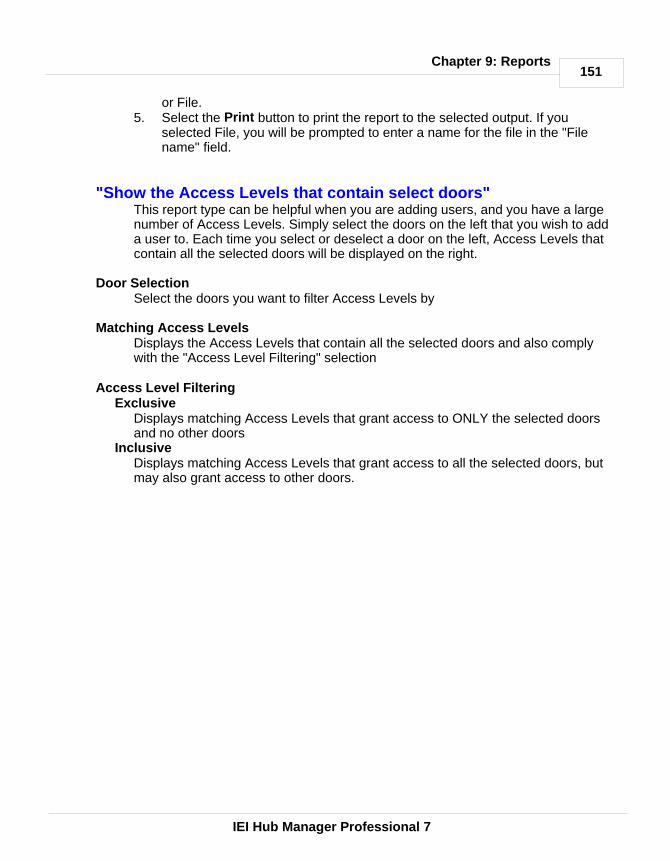
151
IEI Hub Manager Professional 7
Chapter 9: Reports
or File. 5. Select the Print button to print the report to the selected output. If you
selected File, you will be prompted to enter a name for the file in the "Filename" field.
"Show the Access Levels that contain select doors"This report type can be helpful when you are adding users, and you have a largenumber of Access Levels. Simply select the doors on the left that you wish to adda user to. Each time you select or deselect a door on the left, Access Levels thatcontain all the selected doors will be displayed on the right.
Door SelectionSelect the doors you want to filter Access Levels by
Matching Access LevelsDisplays the Access Levels that contain all the selected doors and also complywith the "Access Level Filtering" selection
Access Level FilteringExclusive
Displays matching Access Levels that grant access to ONLY the selected doorsand no other doors
Inclusive Displays matching Access Levels that grant access to all the selected doors, butmay also grant access to other doors.

152
IEI Hub Manager Professional 7
Chapter 9: Reports
Door Selection Screen

153
IEI Hub Manager Professional 7
Chapter 9: Reports
Print Report to Monitor
"Show the Users assigned to each door"This report will display the users that are assigned to each of the selected doors.You have the option to not display particular data in the report, which can help youto distribute this report but still maintain security.
Door SelectionSelect the doors you want to include in the report
Show these items in the user reportPIN Data
Disabling this option, will cause the PIN field to be replaced with an "X" (if that fieldcontains data). In the previous sample report PIN data was disabled, so you willnotice that all the data in the PIN fields are replaced by an X.
Card DataDisabling this option, will cause the Card data fields to be replaced with an "X" (ifany of those fields contain data).
NOTE: If you include either PIN data or Card Data in this report, and the report isprinted to a hard copy or saved to a file, be sure to keep the report in a securelocation, since data in that report could potentially be used to gain access.
Master UserDisabling this option will cause the PIN and Card data fields of the Master User tobe replaced by an "X" (if any of those fields contain data). This can be helpful ifyou want to distribute this report to someone but you do not want that person to beable to enter programming mode manually.
Supervisor UserDisabling this option will cause the PIN and Card data fields of the SupervisorUser to be replaced by an "X" (if any of those fields contain data). This can behelpful if you want to distribute this report to someone but you do not want thatperson to be able to enter programming mode manually.

154
IEI Hub Manager Professional 7
Chapter 9: Reports
Door Selection Screen

155
IEI Hub Manager Professional 7
Chapter 9: Reports
Print Report to Monitor
"Show the Doors each User can access"This report will display the Doors and Time Zones that each of the selected userscan access. This report can help you decide if the Access Level you haveassigned to this user is the best choice, based upon the doors that user hasaccess to.
User SelectionSelect the Users you want to include in this report

156
IEI Hub Manager Professional 7
Chapter 9: Reports
User Selection Screen

157
IEI Hub Manager Professional 7
Chapter 9: Reports
Print Report to Monitor
"Show the Users assigned to each Access Level" This report will display all the Users that are assigned to each of the selectedAccess Levels.
Access Level SelectionSelect the Access Levels you want included in the report
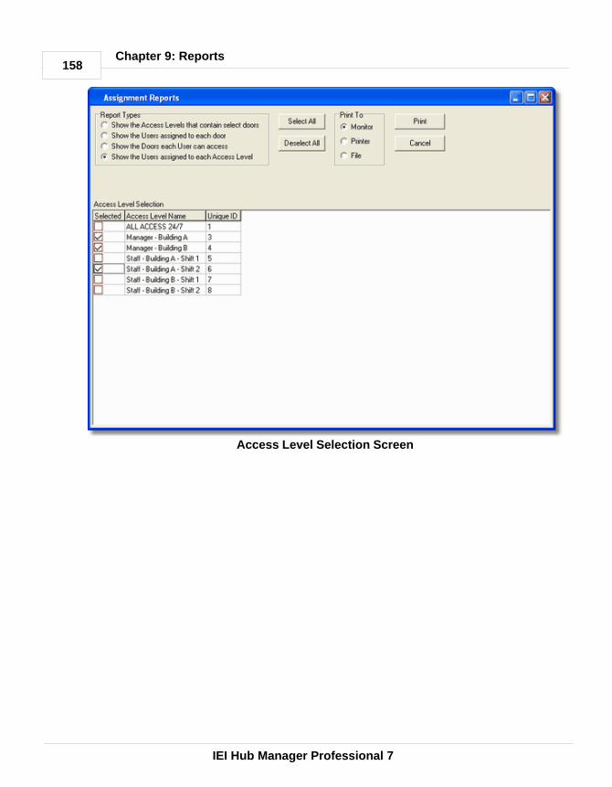
158
IEI Hub Manager Professional 7
Chapter 9: Reports
Access Level Selection Screen

159
IEI Hub Manager Professional 7
Chapter 9: Reports
Print Report to Monitor
9.6 Database Printing
The Database report shows all programmed items within a certain database.Simply select the type of Database report you would like to generate.
1. Select Reports > Database from the Hub Manager Professionalmain menu.The Database screen displays.
2. Specify the information to appear on the report on the Database screen. Youcan select the contents of these databases: Time Zones, sites, doors, accesslevels, users, and holidays.
3. Specify the desired output device for the report: Monitor (screen), Printer, orFile; if you select File, you must enter a name for the file in the "Filename"field. "Monitor" is the default choice. Select the Print button to print the report.

160
IEI Hub Manager Professional 7
Chapter 9: Reports
9.7 Audit Report
The Audit report contains a listing of operator activity, database modifications, andtimes of the activity.
1. Select Reports > Audit from the Hub Manager Professional main menu. TheAudit screen displays. All Audit Trail data displays.
2. Specify the desired output device for the report: Monitor (screen), Printer, orFile; if you select File, you must enter a name for the file in the "Filename"field. "Monitor" is the default choice. Select the Print button to print the report.

161
IEI Hub Manager Professional 7
Chapter 9: Reports
9.8 Archive Viewer
The Archive Viewer report permits you to open either Log or Audit archives forviewing. For more information on archiving, see Log Archiving and Audit Archiving.
1. Select Reports > Archive Viewer from the Hub Manager Professional mainmenu. The Archive Viewer screen displays.

162
IEI Hub Manager Professional 7
Chapter 9: Reports
2. Specify the desired type of Archive report, "Log" or "Audit" and select theOpen button. A Select Archive screen displays, with which you select the Logor Audit file you wish to view. You can navigate to the desired directory usingstandard Windows techniques.
3. To print these files, open them in another program that can read .CSV filessuch as Microsoft Excel.
9.9 Generate Data for External Report Writer
This option will start the Report Writer Database Copy.
See Tools > Options for details on the 'Generate Report Database' option.
9.10 Scheduled Log Imort Errors
The Schedule Log Import Errors report presents a list of recorded error eventswith a description for each. These are errors that occur either during thescheduled importing of transaction logs. The program operates in this fashionbecause both of these options import the logs even if an operator is not present,and some method is required to determine if any errors occurred during theautomated process.
Select Reports > Scheduled Log Import Errors from the main menu. Thesystem processes your request for this report and then displays the results. Afterviewing the errors, the errors are moved into the Audit Trail log.

163
IEI Hub Manager Professional 7
Chapter 9: Reports

164
IEI Hub Manager Professional 7
Chapter 10: Help
Chapter 10: Help
10.1 Error Messages
Here are some error messages and potential resolutions:
When I run Hub Manager Professional I receive an error of: Network Initialization Failed. Permission Denied. File C:\PDOXUSRS.NETDirectory C:\This error is commonly seen on Win 2000 or Win XP and is normally caused byrestrictive permissions of the Windows login user name that is currently logged in.The database engine may require a system drive to store temporary files. Systemdrive access may require Administrator rights.
RESOLUTION: Have the administrator change the permissions of this Windowslogin to have access to the C:\ drive, or give this user full administrator privileges.
When I install Hub Manager Professional I receive an error of "InsufficientDisk space". This error is commonly seen on Win 2000 or Win XP and is normally caused byrestrictive permissions of the Windows login user name that is currently logged in.
RESOLUTION: Have the administrator change the permissions of this Windowslogin to give this user full administrator privileges.
When I try to save a record I receive an error of "Saving error". This error is commonly seen on Win 2000 or Win XP and is normally caused byrestrictive permissions of the Windows login user name that is currently logged in.
RESOLUTION: Have the administrator change the permissions of this Windowslogin to give this user full administrator privileges.
10.2 Glossary
Auto Unlock When this feature is enabled the Time Zones specified asAuto-Unlock Time Zones will be used to automatically unlock at the Time Zonestart time and re-lock at the Time Zone stop time.
Card Number The card number is the electronic code contained in an accesscard or other access credential stored in the card field that is used to perform anaction on a door controller. The card number is read electronically by a cardreader. (This definition also applies to Magnetic (ABA Track II) cards, Proximitycards, RF Fobs and Dallas Touch Chips.)

165
IEI Hub Manager Professional 7
Chapter 10: Help
Code Number The access number that the user enters on a keypad to gainaccess to a door. It can be 1 to 6 digits in length. The longer the code, the greaterthe security. It only takes 9 attempts to find a 1-digit code.
Code PIN See Code Number.
Com Port This is the serial communication port on a personal computer throughwhich the Hub Manager Professional software communicates with thehardwired controller network.
DB9 This is a 9-pin connector that is shaped like an elongated "D"; it can be foundon the back of a computer. A typical IBM compatible PC has a DB9 connector forthe COM1 and COM3 com ports.
DB25 This is a 25-pin connector that is shaped like an elongated "D"; it can befound on the back of a computer. A typical IBM compatible PC has a DB25connector for the COM2 and COM4 com ports.
Door In this manual, the term door is used synonymously with the term controller,Door Controller, or Door Control Module. When referring to "Door Status"what isreally being said is "Controller Status."
Export The action of sending Door Settings information from the Hub ManagerProfessional software to the controllers.
Forced Door Alarm This is the programmable feature in a controller whereby theForced Door relay located in the controller is activated for a specified time whenthe controller detects that a locked door has been forced open. NOTE: Thisrequires that a door position detection device has been properly installed.
Import The action of retrieving information from the controller network into theHub Manager Professional software.
Keypress Feedback This is a feature of the controller whereby a yellow LED lightis flashed or a sonalert device is beeped (depending on installed equipment) witheach keypress on a keypad.
Log Short for Transaction Log. The log is a list of recorded events for a particulardoor.
Master Code This code is used to enter programming mode on a controller. It islocated in User #1. The name of User #1 is defaulted to "Master User".
Operator Person who is using the Hub Manager Professional and SystemManager software.

166
IEI Hub Manager Professional 7
Chapter 10: Help
PIN Acronym for Personal Identification Number. See Code Number.
System Administrator Operator responsible for managing the access controlsystem.
System Dataset (aka Dataset or System) A 'System Dataset' is a compressedzip file that stores all the data that is related to that particular System, currentlyincluding (but not limited to) the complete contents of the following folders:Archive, Backup, Database, Gateway, Maps, PDAFiles, Print, and ReportDB.
System Manager System Manager is a program that is responsible for accessingthe System Repository and loading System datasets onto the local PC. SystemManager also sends that same dataset back to the System Repository.
System Repository (aka Repository, or Repository folder) A 'SystemRepository' is a folder that can store any number of System Datasets. Any numberof System Repository folders can be created based upon your security needs. Allsystems stored in that repository can be accessed by any installation of SystemManager that has network privileges to see that particular System Repositoryfolder.
10.3 Help
The electronic Help file is context sensitive. This means, for example, that if youpress F1 while the Access Levels Edit screen is open in Hub ManagerProfessional, the Help file opens to the topic that describes Access Levels.
10.4 Check for Updates
iUpdate is a feature that checks for and installs any updates that are found for the Hub Manager Professional software. No sensitive information is sent during thisprocess.
NOTE: This feature requires an active internet connection.
1. Upon selecting this option from the Hub Manager Professional main menu Help> Check for Updates, the program will attempt to establish a connection withan update server located on the internet.
NOTE: When Hub Manager Professional is run, you will also be prompted tocheck for updates, but you will only be prompted once per day. If you do not wantto be prompted you can have Hub Manager Professional automatically check foravailable updates and only alert you if an update was found. Or you can turn offthe auto checking completely (not recommended). These options are located in Tools > Options > General Options.
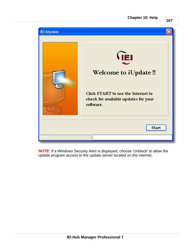
167
IEI Hub Manager Professional 7
Chapter 10: Help
NOTE: If a Windows Security Alert is displayed, choose 'Unblock' to allow theupdate program access to the update server located on the internet.

168
IEI Hub Manager Professional 7
Chapter 10: Help
2. If the server is found then any available updates will be displayed.

169
IEI Hub Manager Professional 7
Chapter 10: Help
3. Select Next to start downloading and installing the updates. You may berequired to run the update again, depending upon which pieces needed to beupdated.
4. When all updates are complete you will receive a final message stating that allcomponents are up to date, and Hub Manager Professional will be restarted.

170
IEI Hub Manager Professional 7
Chapter 10: Help
10.5 Check for Custom Updates
This option will check for special updates that are distributed on an individualbasis. In order to use this feature you will need the Custom Update Informationprovided to you. This information includes the iUpdate server, login name andpassword.
No sensitive information is sent during this process.
NOTE: This feature requires an active internet connection.
1. Upon selecting this option from the Hub Manager Professional main menu Help> Check for Custom Updates, the program will ask you for the Server IPAddress, Login Name, and Login Password.
2. iUpdate will then attempt to establish a connection with the specified updateserver located on the internet.
3. Any available updates will be displayed. Select Next to start the download

171
IEI Hub Manager Professional 7
Chapter 10: Help
process.
4. Hub Manager Professional will be restarted when the download and installationprocess is complete.
10.6 About
This screen contains information about the Hub Manager Professional program.This is also the screen where you can edit the support contact information thatappears in the lower right of the main screen. In order to edit these fields, youmust log in to the program using the Administrator login name and password. Thislogin was initially named HUBMAN, but may have been changed. If you havemore than one login operator in the system and you are not sure which one is theAdministrator, it is easy to recognize. Assuming your login has full access rights tothe operator database, if you open each operator in the list for editing, theAdministrator operator will have the Toggle, Enable All and the Disable All buttonsdisabled (the text will appear gray, see below).
If you now log in with this operator and go to Help > About, you can now edit theSupport Contact Information.
The Administrator Operator always has FULL access to all areas of the program.

172
IEI Hub Manager Professional 7
Chapter 10: Help
The options can not be edited, and this operator can never be deleted.
see also:Obtaining Technical Support

173
IEI Hub Manager Professional 7
Chapter 11: Obtaining Technical Support
Chapter 11: Obtaining Technical Support
11.1 Obtaining Technical Support
Should you experience any difficulty installing or operating the Hub ManagerProfessional software, please contact your installer or contact IEI at 800-343-9502.
The installer information can be found in the bottom right corner of the HubManager Professional main screen, or go to Help > About.
174
IEI Hub Manager Professional 7
Chapter 12: Copyright Information
Chapter 12: Copyright Information
12.1 Copyright Information
Copyright © 2005 by International Electronics, Inc.. All Rights Reserved. HubManager Professional, LS2\P are trademarks of International Electronics, Inc..
Microsoft®, Microsoft Excel®, Windows 2000®, and Windows XP® areregistered trademarks of Microsoft Corporation. OMAP™ is a trademark of TexasInstruments. Other company or product names mentioned herein may betrademarks or registered trademarks of their respective companies.
Index175
IEI Hub Manager Professional 7
Index- 2 -24 Hours 82
- A -About 171
Access Condition 96
Access Level Setup 96
Access Levels 96
Add User Group 117
Administrator 11
Application Initialization 138
Archive Viewer 161
Archiving 127
Assigned Doors 61
Assignment Reports 150
Audit Archiving 128
Audit Trail Report 160
Auto Configuration 125
Auto Unlock Time Zone 86
Autorun 7
- B -Backup Alert 139
Batch Load Users 117
Block Holiday 119
- C -Capacity 86
Card 103
Card Format 103
Change Login Password 56
Check for Custom Updates 170
Check for Updates 166
Com Port 64
Com Port Test 133
Communications
Export Data to Doors 123
Import Door Settings 122
Import Transaction Log 123
Network Query 125
Update Time/Date 123
Connect 61
Connection
LAN 64
Modem 79
PDA 64
Serial 64
Connection Type 61
Parameters 61
Contact Information 171
Controller Status 125
Conversion Utility 130
Copyright Information 174
Corporate Code 103
Crystal Reports 162
Crystal Reports Compatibility 139
- D -Data Conversion 130
Database 58
Access Levels 96
Doors 86
Holidays 119
Menu 58
Operators 58
Sites 61
Time Zones 82
Users 103

176
IEI Hub Manager Professional 7
Index
Database Backup\Restore 129
Database Printing 159
Date Setting 123
Days Allowed after First Use 103
Deselect Door 96
Device Group 61
Device Type
Hub Controllers 93
LS2\P 94
prox.pad plus 93
DHCP 64, 70, 73
Disconnect 61
Door
Address 86
Device Type 86
Log Event Mask 86
Name 86
Site 86
System Options 86
System Parameters 86
Time Zones 86
Door Settings 86
Doors
Door Type 86
Type 86
Dynamic IP Address 64, 70, 73
- E -Emergency User 96
Enrollment Station 103
Error Messages
Insuffiecient Disk Space 164
Network Initialization Failed 164
Saving Error 164
Event
Unknown User ID 144
Event Log 123
Events 123
Exit 56
Export data to Doors 123
Export Time/Date 123
Extended Unlock User 96
External Tools 133, 134
- F -Fob Button 103
Foreword 3
- G -Generate Data for External Report Writer 162
Glossary 164
Group 117
Group Code 103
- H -Help 1
About 171
Check for Custom Updates 170
Check for Updates 166
Help 166
HID Cards 103
HID Prox Cards 103
Holidays 119
Hub Manager Professional Installation 7
- I -Import Door Settings 122
Import Log 123
Indexing 138
Indexing error 138
Initial Setup 19
Installation

Index177
IEI Hub Manager Professional 7
Installation
PC Software 7
PDA Software 7
IP Address 64, 70, 73
- L -LAN 64
Lockdown User (Panic) 96
Lockout User 96
Log 123
Log Archiving 127
Log Filter 144
Log Importing 123
Login 11, 55
Logout 55
LS Link 28, 64, 94
LS Link Installation 7
LS2\P 94
- M -Main Menu 22
Manual Conventions 3
Master Code 103
Master User 96
Menu
Database 58
Tools 127
Menu System 22
Midnight Crossing 82
Migrating Data 130
Misc. Log Reports 149
Multiple databases 40
Multiple Systems 40
- N -Name List Import 114
Navigating through the Program 22
Network Query 125
Number of Total Uses 103
- O -Online Updates 166, 170
Operator 55, 56
Audit Trail Report 160
Operator Wizard 60
Operators 58
Options 139
Overview
Converting data 130
General Overview 11
Initial Setup 19
Menu System 22
PDA Software 28
Running the software 24
Uninstall 38
- P -Palm OS Software 7, 28
Panic User 96
Passage User 96
Password 55
PDA 61
PDA Application 64
PDA Software 7, 28
PIN 103
prox.pad plus 93

178
IEI Hub Manager Professional 7
Index
- Q -Query Now 125
- R -Random PIN 103
Raw Data 103
Relock 96
Report Writer 139
Reports
Archive Viewer 161
Assignment Reports 150
Audit 160
Database Printing 159
Generate Data for External Report Writer 162
Log Filter 144
Misc. Log Reports 149
Scheduled Log Import Errors 162
Time Management 148
RF Fob 103
RS232 - RS485 Converter 64
Run Com Port Test 133
Running the software 24
- S -Scheduled Log Import 56, 134
Scheduled Log Import Errors 162
Security chip 122
SEG 64, 70, 73
Sending Data to a Door 123
Serial 64
Serial Converter 64
Settings
Door 86
Setup 19
Setup Wizards 95, 102, 114
Single Use 96
Site Code 103
Site Wizard 63
Sites 61
Start/Stop 103
Static IP Address 64, 73
Supervisor Code 103
Supervisor User 96
System 40
Change Password 56
Exit 56
Login 55
Logout 56
System Manager 40
System Dataset 40
System Manager 139
Clear System List 40
Close System 40
Create System 40
Define Existing Repository 40
Delete System 40
Emergency Override 40
Open System 40
Rename System 40
System Repository 40
Systems
Multiple 40
- T -Table Initialization 136
Tecnincal Support 173
Temporary Users 103
Time Management 103, 148
Time Setting 123
Time Zone Selections 96
Time Zones 86
TimeZones 82

Index179
IEI Hub Manager Professional 7
Tools
Application Initialization 127, 138
Audit Archiving 127, 128
Backup Alert 139
Database Backup/Restore 127
Database Backup\Restore 129
External Tools 127, 134
Indexing 127, 138
Log Archiving 127
Options 139
Report Writer 139
Run Com Port Test 127, 133
Scheduled Log Import 127, 134
Scheduled Log Import Reminder 136
System Manager 139
Table Initialization 127, 136
Transaction Log 123
Transaction Log Importing 123
Type 96
- U -Uninstall 38
Unknown User ID Event 144
Updates 166, 170
User Name List Import 114
User Type 96
Extended Unlock 96
Lockdown (Panic) 96
Lockout 96
Master 96
Passage (Toggle) 96
Standard 96
Supervisor 96
Toggle (Passage) 96
Users 103
Add Batch of Users 117
Add Group of Users 117
- V -Visual ID 103
- W -Walkthrough 24
Warning Messages
User Capacity Exceeded 114
Warranty 3
Windows Logon 11
Wizards 63, 95, 102, 114
Access Level 102
Door 95
Site Wizard 63
User List Import Wizard 114