Embed Size (px)
Citation preview

Visualizing Design Patterns inTheir Applications and Compositions
Jing Dong, Member, IEEE, Sheng Yang, Member, IEEE, and Kang Zhang, Senior Member, IEEE
Abstract—Design patterns are generic design solutions that can be applied and composed in different applications where pattern-
related information is generally implicit in the Unified Modeling Language (UML) diagrams of the applications. It is unclear in which
pattern instances each modeling element, such as class, attribute, and operation, participates. It is hard for a designer to find the
design patterns used in an application design. Consequently, the benefits of design patterns are compromised because designers
cannot communicate with each other in terms of the design patterns they used and their design decisions and trade-offs. In this paper,
we present a UML profile that defines new stereotypes, tagged values, and constraints for tracing design patterns in UML diagrams.
These new stereotypes and tagged values are attached to a modeling element to explicitly represent the role the modeling element
plays in a design pattern so that the user can identify the pattern in a UML diagram. Based on this profile, we also develop a Web
service (tool) for explicitly visualizing design patterns in UML diagrams. With this service, users are able to visualize design patterns in
their applications and compositions because pattern-related information can be dynamically displayed. A real-world case study and a
comparative experiment with existing approaches are conducted to evaluate our approach.
Index Terms—Design pattern, UML, model-driven architecture, Web service, visual tool.
Ç
1 INTRODUCTION
APPLYING design patterns [6], [8], [19], [21], [41] insoftware designs support the reuse of expert design
experiences to solve recurring problems. Design patternshelp designers communicate architectural knowledge, helppeople learn a new design paradigm, and help newdevelopers avoid traps and pitfalls that have traditionallybeen learned only by costly experiences. Design patterns areusually modeled and documented in natural languages andvisual notations such as the Unified Modeling Language(UML) [5], [43], [52]. UML is a family of modeling notationsfor specifying, visualizing, constructing, and documentingartifacts of software-intensive systems. It provides acollection of visual notations to capture different aspectsof the system under development.
Each design pattern normally contains several partici-
pants such as classes, attributes, and operations, which play
certain roles manifested by their names. When the design
pattern is applied or composed in an application, the role
names of its participants may be adapted to reflect the
application domain. Thus, pattern-related information,
represented by the role names, is lost. It is hard to identify
in which patterns a modeling element, such as class,
attribute, and operation, participates in an application
design. The designers are not able to trace this information
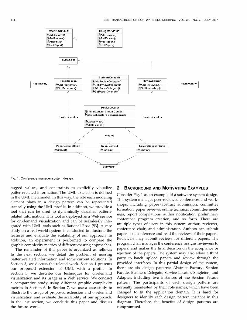
in the application design. For instance, Fig. 1 shows a
software system design containing six design patterns:
Abstract Factory, Session Facade, Business Delegate, ServiceLocator, Singleton, and Adapter. It is hard to identify theparticipants of each design pattern in this diagram becauseall pattern-related information is implicit. There are severalproblems when design patterns are implicit in softwaresystem designs. First, software developers can only com-municate at the class level instead of the pattern levelbecause they do not have pattern-related information insystem designs. Second, each pattern often documents someways for future evolutions [2], which are buried in thesystem design. The designers are not able to change thedesign using relevant pattern-related information. Third,each pattern may preserve some properties and constraints.It is hard for the designers to check whether theseproperties and constraints hold when the design is changed.Fourth, it may require considerable effort on reverse-engineering design patterns from software systems [24],[26], [28], [29], [39].
As the de facto standard for object-oriented modeling,the UML is defined within a general four-layer metamodel-ing architecture: metametamodel, metamodel, model, anduser objects. The metametamodel layer defines a languagefor specifying the metamodel layer. The metamodel layer,in turn, defines a language for specifying the model layer.Similarly, the model layer is used to define models ofspecific software systems. The user objects layer is used todefine software systems of a given model. For example, theUML metamodel defines all legal UML specifications. TheUML model defines a model of software systems that maybe instantiated into user objects. The metamodel and modellayers are most relevant to modeling design patterns inUML. A UML profile may be used to define an extension tothe UML at the metamodel level.
In this paper, we present a UML profile for designpatterns, which extends the UML with new stereotypes,
IEEE TRANSACTIONS ON SOFTWARE ENGINEERING, VOL. 33, NO. 7, JULY 2007 433
. The authors are with the Department of Computer Science, University ofTexas at Dallas, 2601 North Floyd Road, Richardson, TX 75083.E-mail: {jdong, syang, kzhang}@utdallas.edu.
Manuscript received 28 May 2006; revised 20 Dec. 2006; accepted 15 Mar.2007; published online 9 Apr. 2007.Recommended for acceptance by B. Cheng.For information on obtaining reprints of this article, please send e-mail to:[email protected], and reference IEEECS Log Number TSE-0115-0506.Digital Object Identifier no. 10.1109/TSE.2007.1012.
0098-5589/07/$25.00 � 2007 IEEE Published by the IEEE Computer Society
tagged values, and constraints to explicitly visualizepattern-related information. The UML extension is definedin the UML metamodel. In this way, the role each modelingelement plays in a design pattern can be representedstatically using the UML profile. In addition, we provide atool that can be used to dynamically visualize pattern-related information. This tool is deployed as a Web servicefor on-demand visualization and can be seamlessly inte-grated with UML tools such as Rational Rose [53]. A casestudy on a real-world system is conducted to illustrate thefeatures and evaluate the scalability of our approach. Inaddition, an experiment is performed to compare thegraphic complexity metrics of different existing approaches.
The remainder of this paper is organized as follows:In the next section, we detail the problem of missingpattern-related information and some current solutions. InSection 3, we discuss the related work. Section 4 presentsour proposed extension of UML with a profile. InSection 5, we describe our techniques for on-demandvisualization and its usage as a Web service. We conducta comparative study using different graphic complexitymetrics in Section 6. In Section 7, we use a case study toillustrate the usage of proposed extension and on-demandvisualization and evaluate the scalability of our approach.In the last section, we conclude this paper and discussthe future work.
2 BACKGROUND AND MOTIVATING EXAMPLES
Consider Fig. 1 as an example of a software system design.
This system manages peer-reviewed conferences and work-
shops, including paper/abstract submission, committee
formation, paper reviews, online technical committee meet-
ings, report compilations, author notification, preliminary
conference program creation, and so forth. There are
multiple types of users in this system: author, reviewer,
conference chair, and administrator. Authors can submit
papers to a conference and read the reviews of their papers.
Reviewers may submit reviews for different papers. The
program chair manages the conference, assigns reviewers to
papers, and makes the final decision on the acceptance or
rejection of the papers. The system may also allow a third
party to batch upload papers and review through the
provided interfaces. In this partial design of the system,
there are six design patterns: Abstract Factory, Session
Facade, Business Delegate, Service Locator, Singleton, and
Adapter, including two instances of the Session Facade
pattern. The participants of each design pattern are
normally manifested by their role names, which have been
changed to fit the application domain. It is hard for
designers to identify each design pattern instance in this
diagram. Therefore, the benefits of design patterns are
compromised.
434 IEEE TRANSACTIONS ON SOFTWARE ENGINEERING, VOL. 33, NO. 7, JULY 2007
Fig. 1. Conference manager system design.
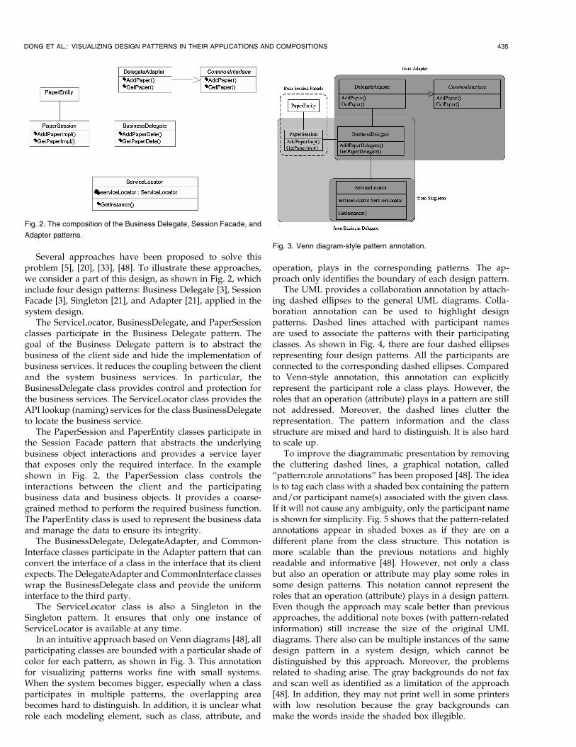
Several approaches have been proposed to solve thisproblem [5], [20], [33], [48]. To illustrate these approaches,we consider a part of this design, as shown in Fig. 2, whichinclude four design patterns: Business Delegate [3], SessionFacade [3], Singleton [21], and Adapter [21], applied in thesystem design.
The ServiceLocator, BusinessDelegate, and PaperSessionclasses participate in the Business Delegate pattern. Thegoal of the Business Delegate pattern is to abstract thebusiness of the client side and hide the implementation ofbusiness services. It reduces the coupling between the clientand the system business services. In particular, theBusinessDelegate class provides control and protection forthe business services. The ServiceLocator class provides theAPI lookup (naming) services for the class BusinessDelegateto locate the business service.
The PaperSession and PaperEntity classes participate inthe Session Facade pattern that abstracts the underlyingbusiness object interactions and provides a service layerthat exposes only the required interface. In the exampleshown in Fig. 2, the PaperSession class controls theinteractions between the client and the participatingbusiness data and business objects. It provides a coarse-grained method to perform the required business function.The PaperEntity class is used to represent the business dataand manage the data to ensure its integrity.
The BusinessDelegate, DelegateAdapter, and Common-Interface classes participate in the Adapter pattern that canconvert the interface of a class in the interface that its clientexpects. The DelegateAdapter and CommonInterface classeswrap the BusinessDelegate class and provide the uniforminterface to the third party.
The ServiceLocator class is also a Singleton in theSingleton pattern. It ensures that only one instance ofServiceLocator is available at any time.
In an intuitive approach based on Venn diagrams [48], allparticipating classes are bounded with a particular shade ofcolor for each pattern, as shown in Fig. 3. This annotationfor visualizing patterns works fine with small systems.When the system becomes bigger, especially when a classparticipates in multiple patterns, the overlapping areabecomes hard to distinguish. In addition, it is unclear whatrole each modeling element, such as class, attribute, and
operation, plays in the corresponding patterns. The ap-proach only identifies the boundary of each design pattern.
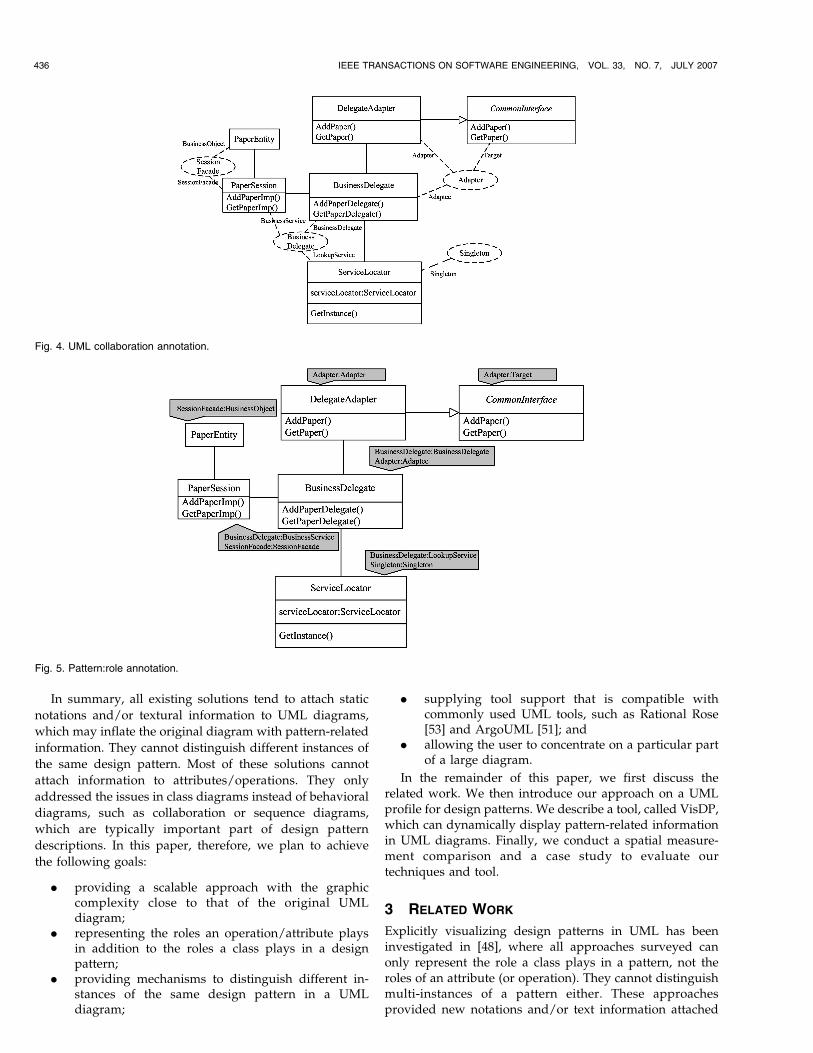
The UML provides a collaboration annotation by attach-ing dashed ellipses to the general UML diagrams. Colla-boration annotation can be used to highlight designpatterns. Dashed lines attached with participant namesare used to associate the patterns with their participatingclasses. As shown in Fig. 4, there are four dashed ellipsesrepresenting four design patterns. All the participants areconnected to the corresponding dashed ellipses. Comparedto Venn-style annotation, this annotation can explicitlyrepresent the participant role a class plays. However, theroles that an operation (attribute) plays in a pattern are stillnot addressed. Moreover, the dashed lines clutter therepresentation. The pattern information and the classstructure are mixed and hard to distinguish. It is also hardto scale up.
To improve the diagrammatic presentation by removingthe cluttering dashed lines, a graphical notation, called“pattern:role annotations” has been proposed [48]. The ideais to tag each class with a shaded box containing the patternand/or participant name(s) associated with the given class.If it will not cause any ambiguity, only the participant nameis shown for simplicity. Fig. 5 shows that the pattern-relatedannotations appear in shaded boxes as if they are on adifferent plane from the class structure. This notation ismore scalable than the previous notations and highlyreadable and informative [48]. However, not only a classbut also an operation or attribute may play some roles insome design patterns. This notation cannot represent theroles that an operation (attribute) plays in a design pattern.Even though the approach may scale better than previousapproaches, the additional note boxes (with pattern-relatedinformation) still increase the size of the original UMLdiagrams. There also can be multiple instances of the samedesign pattern in a system design, which cannot bedistinguished by this approach. Moreover, the problemsrelated to shading arise. The gray backgrounds do not faxand scan well as identified as a limitation of the approach[48]. In addition, they may not print well in some printerswith low resolution because the gray backgrounds canmake the words inside the shaded box illegible.
DONG ET AL.: VISUALIZING DESIGN PATTERNS IN THEIR APPLICATIONS AND COMPOSITIONS 435
Fig. 2. The composition of the Business Delegate, Session Facade, and
Adapter patterns.
Fig. 3. Venn diagram-style pattern annotation.
In summary, all existing solutions tend to attach static
notations and/or textural information to UML diagrams,
which may inflate the original diagram with pattern-related
information. They cannot distinguish different instances of
the same design pattern. Most of these solutions cannot
attach information to attributes/operations. They only
addressed the issues in class diagrams instead of behavioral
diagrams, such as collaboration or sequence diagrams,
which are typically important part of design pattern
descriptions. In this paper, therefore, we plan to achieve
the following goals:
. providing a scalable approach with the graphiccomplexity close to that of the original UMLdiagram;
. representing the roles an operation/attribute playsin addition to the roles a class plays in a designpattern;
. providing mechanisms to distinguish different in-stances of the same design pattern in a UMLdiagram;
. supplying tool support that is compatible withcommonly used UML tools, such as Rational Rose[53] and ArgoUML [51]; and
. allowing the user to concentrate on a particular partof a large diagram.
In the remainder of this paper, we first discuss therelated work. We then introduce our approach on a UMLprofile for design patterns. We describe a tool, called VisDP,which can dynamically display pattern-related informationin UML diagrams. Finally, we conduct a spatial measure-ment comparison and a case study to evaluate ourtechniques and tool.
3 RELATED WORK
Explicitly visualizing design patterns in UML has beeninvestigated in [48], where all approaches surveyed canonly represent the role a class plays in a pattern, not theroles of an attribute (or operation). They cannot distinguishmulti-instances of a pattern either. These approachesprovided new notations and/or text information attached
436 IEEE TRANSACTIONS ON SOFTWARE ENGINEERING, VOL. 33, NO. 7, JULY 2007
Fig. 5. Pattern:role annotation.
Fig. 4. UML collaboration annotation.
to the UML diagrams to represent pattern-related informa-tion. Nevertheless, the additional information is static anddoes not scale well. In this paper, we presented a UMLprofile that can represent the role an attribute (operation), aswell as a class, plays in a design pattern and distinguishmulti-instances of a design pattern. Our approach can beseamlessly integrated with the UML standards. We proposeto dynamically visualize design patterns to overcome thescalability problem of all the static approaches. In this way,we hide all pattern-related information and allow the userto visualize design patterns on demand. All pattern-relatedinformation is displayed only when requested.
France et al. [20] specialized the UML metamodel toobtain a pattern specification. Pattern-related information isdefined as roles in subtypes of UML metamodel in aseparate diagram. Thus, the generic specifications of eachdesign pattern are represented in a separate diagram fromthe applications of the corresponding pattern. The applica-tion of a design pattern is mapped to its generic specifica-tions by dotted lines with arrow heads. The user is able tovisualize pattern-related information from these dottedlines. In this case, pattern specifications always need to bepresented for the user to visualize pattern-related informa-tion in a UML diagram. The pattern specification diagramand the dotted lines bound to the corresponding patternapplication are static information added on normal UMLdiagram. The main goal of the approach is to find a practicalway for specifying design patterns. Our goal, on the otherhand, focuses on providing a scalable solution on visualizingdesign patterns. We also take into account the composition ofpatterns and multi-instance of patterns. We consider ourapproaches to complement those of France et al.
Reiss [42] proposed a specification language for definingdesign patterns that breaks a design pattern down intoelements and constraints over a database storing thestructural and semantic information of a program. Eachsystem has a database to store the design patterns definedin this language. Design pattern instances can be created,found, maintained, and edited by querying the database.Based on this language, a tool is developed to allow the userto identify and create pattern instances in the source code.The objective of his approach is to facilitate the applicationand discovery of design patterns, instead of visualizingthem based on their generic specifications.
Logic-based languages have been presented to expressunambiguously the solutions proposed by design patterns[1], [16], [37]. Visual notations consisting of icons (ovals,triangles, and squares) are proposed to make the formallanguages more accessible to novice users [16]. The maingoal of these formal approaches is to reduce ambiguity inthe specification of design patterns in informal languages,not to display instances.
General design recovery frameworks have been investi-gated [22], [23]. Tool support for applying (forwardengineering) and discovering (reverse engineering) designpatterns has also been developed [17]. This tool is based onthe fragment model and fragment database. Although thefragment structure diagram can be used to visualize the roleeach class (attribute or operation) plays in a design pattern,it does not keep the topology of the original UML diagram,
and so the class model information is lost. The tool cannotvisualize a program purely in terms of pattern instances.
Lander and Kent [31] propose an approach to specifyinga design pattern in type model and role model in additionto class model to tackle the impure pattern modelingproblem due to the difficulty of expressing nondetermi-nistic number of concrete classes using UML. Whenseveral patterns are composed, the three models and themapping among them become very complex. The maingoal of their work is to provide a more expressiveapproach to specifying design patterns although theirapproach can trace design pattern from type/role model toclass model. Instead of introducing new types of diagrams,the goals of our approach are scalability, practice, and easyto learn and use.
Design Pattern Modelling Language (DPML) has beenproposed to model and apply design patterns [33]. Incontrast to our approach that constraints UML, DPMLprovides new notations such as hexagon and invertedtriangle for modeling design patterns. It improves theexpressiveness for some special concepts, for example,dimension, of design patterns. A tool is also provided todraw the new notations. Unlike DPML, our goal is toexplicitly visualize the hidden dependency of a designpattern to its instance link. We also support design patterncomposition, dynamic aspects of design patterns, objectconstraint language, and the overlapping of design patterninstances.
Several limitations of using the UML parameterizedcollaboration diagram to specify and apply design patternsare discussed in [47]. A tool has been provided for thegeneration and reconstruction of design patterns to over-come the limitations. In addition, two stereotypes, <<Clan>>and <<Tribe>> have been defined to model recurringconstraints of design patterns [32]. The <<meta>> stereotypeis defined with some well-formedness rules in OCL toimprove the graphic representation of pattern occurrences.Unlike their goals (generation and reconstruction), ourapproach intends to visualize and recognize design patternsin their applications.
UML extension mechanisms have been used to expandthe expressive power of UML to model object-orientedframework [18], software architecture [27], [35], and agent-oriented systems [49] when the original UML is notsufficient to represent the semantic meaning of the design.We extend UML with a new profile to visualize thepattern-related information hidden in a UML diagram. Wedefine new stereotypes and tagged values and provide theconstraints applied to these stereotypes and tagged values.
UML has been used to visually specify interactivemultimedia application [44] and support for dynamicmodeling [25] with an extension for behavioral specifica-tions. The concept of visual scripting in VISOME [40] isinteresting. The scripting mechanism supports the visualcomposition of high-level functions for software modelingand assists automatic synthesis of different UML diagrams.The usability of UML tools can also be enhanced byadding speech recognition capability [30]. None of theseapproaches, however, address the visualization issues ofdesign patterns in UML.
DONG ET AL.: VISUALIZING DESIGN PATTERNS IN THEIR APPLICATIONS AND COMPOSITIONS 437
To our knowledge, there has been no reactive user
interface similar to ours for visualizing design patterns.
Dynamic user interactive techniques have been used for
information visualization. An example is the hybrid net-
work visualizing software development communities [36].
Due to the large number of nodes representing the names of
developers and edges representing their communications,
the network connection is hidden by default. Relevant
communication details such as e-mail messages are high-
lighted or displayed in popup windows.Tightly integrated into the Eclipse IDE, SEXTANT [45] is
a prototype for software exploration with graph-based
visualization and navigation support. The user can hide
irrelevant information during exploration. The visualization
and navigation support is, however, not designed for
dynamic visualization of design patterns in class diagrams.
4 EXTENDING UML TO VISUALIZE DESIGN
PATTERNS
This section presents our approach for explicit visualization
of design patterns in their applications and compositions
through the same example used in Section 2. We introduce
the UML extensions including new stereotypes, tagged
values, and constraints, and present a general description of
their semantics. We also discuss how the UML extensibility
mechanisms have been applied in the definition of a UML
profile for design patterns.
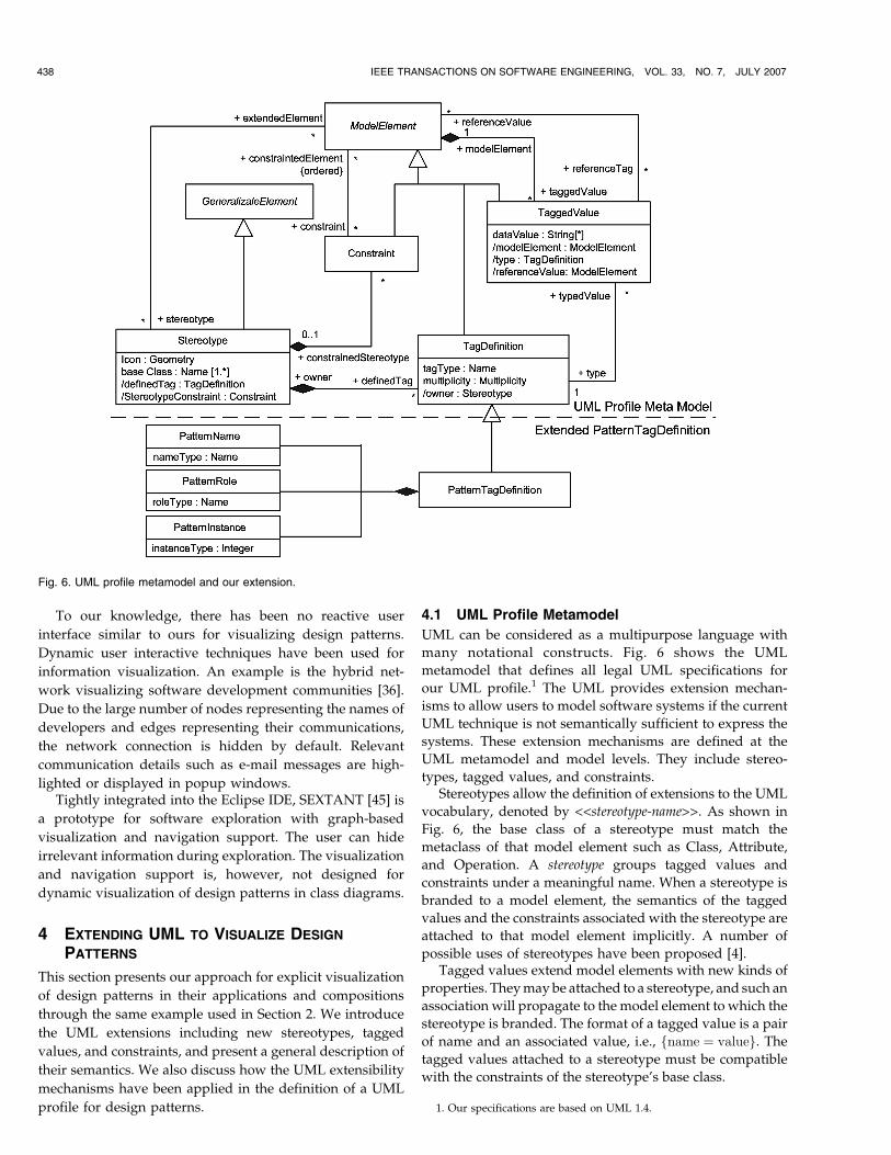
4.1 UML Profile Metamodel
UML can be considered as a multipurpose language with
many notational constructs. Fig. 6 shows the UML
metamodel that defines all legal UML specifications for
our UML profile.1 The UML provides extension mechan-
isms to allow users to model software systems if the current
UML technique is not semantically sufficient to express the
systems. These extension mechanisms are defined at the
UML metamodel and model levels. They include stereo-
types, tagged values, and constraints.Stereotypes allow the definition of extensions to the UML
vocabulary, denoted by <<stereotype-name>>. As shown in
Fig. 6, the base class of a stereotype must match the
metaclass of that model element such as Class, Attribute,
and Operation. A stereotype groups tagged values and
constraints under a meaningful name. When a stereotype is
branded to a model element, the semantics of the tagged
values and the constraints associated with the stereotype are
attached to that model element implicitly. A number of
possible uses of stereotypes have been proposed [4].Tagged values extend model elements with new kinds of
properties. They may be attached to a stereotype, and such an
association will propagate to the model element to which the
stereotype is branded. The format of a tagged value is a pair
of name and an associated value, i.e., fname ¼ valueg. The
tagged values attached to a stereotype must be compatible
with the constraints of the stereotype’s base class.
438 IEEE TRANSACTIONS ON SOFTWARE ENGINEERING, VOL. 33, NO. 7, JULY 2007
1. Our specifications are based on UML 1.4.
Fig. 6. UML profile metamodel and our extension.
Constraints add new semantic restrictions to a modelelement. Typically, constraints are written in the ObjectConstraint Language (OCL) [50]. Constraints attached to astereotype imply that all model elements branded by thatstereotype must obey the semantic restrictions of theconstraints. The constraints attached to a stereotyped modelelement must be compatible with the constraints of thestereotype and the base class of the model element.
A profile is a stereotyped package containing modelelements that have been customized for a specific domainor purpose by extending the metamodel using stereotypes,tagged values, and constraints. A profile may specify modellibraries on which it depends and the metamodel subsetthat it extends.
Fig. 6 shows the relationships among stereotype,constraint, tagged value, and model element. The stereo-type, constraint, and tagged value can be attached to amodel element and add corresponding semantics torestrict the model element. A stereotype may include anumber of tagged values and constraints whose semanticsis propagated from the stereotype to the model elementsto which the stereotype is branded. In our approach, wepropose a new tag definition called PatternTagDefinition,which is inherited from TagDefinition and consists ofthree parts, PatternName, PatternRole, and PatternIn-stance. PatternName has a type of Name, and so doesPatternRole. PatternInstance has a type of integer. Thepart above the dashed line in Fig. 6 is from the UMLmetamodel, whereas the lower part is our new tagdefinition. There are several reasons for us to define anew kind of tag (PatternTagDefinition) instead of reusingthe existing one (TagDefinition). First, we need to restrictthe general definition of tags. This special type of tags isonly used to define the role, pattern name, and instance,which are important for visualization. Second, for theusual TagDefinition, the name of taggedValue is clearlydefined; the variation point is the value of taggedValue.For our new tag definition, the names of taggedValuethemselves are changeable, which may be different fromclass to class. Third, introducing this new tag alsofacilitates our tool support.
4.2 A UML Profile for Design Patterns
We considered three options to extend the UML to explicitlyvisualize pattern-related information usually hidden in UMLdiagrams. The first option is to define three stereotypes:PatternClass, PatternAttribute, and PatternOperation, whosebase classes are Class, Attribute, and Operation, respectively.There is one tagged value defined in each stereotype in thefirst option. The name of the tagged value is “pattern” and thedataValue of the tagged value is a tuple in the format of<name: string [instance: integer], role: string>. The “name” inthe tuple is the pattern name in which a model element, suchas class, attribute, or operation, participates. The “instance” inthe tuple indicates the instance number of the pattern themodel element participates. It can be omitted if there is onlyone instance of the design pattern in the system design. The“role” in the tuple shows the role that a model element playsin the pattern.
The second option is also to define three stereotypes:PatternClass, PatternAttribute, and PatternOperation,
whose base classes are Class, Attribute, and Operation,respectively. There is one tagged value defined for eachstereotype. In contrast to the first option, the name of thetagged value has the format of “role@name[instance]” andthe dataValue of the tagged value is either true or false. Themeanings of fields “name,” “instance,” and “role” are thesame as those in the first option. If the dataValue of a taggedvalue is true, the value can be omitted and only the name ofthe tagged value is shown in a diagram. If this tagged valueis attached to a modeling element, it indicates that themodeling element participates in the “name” pattern withthe role of “role.” The value of “instance” distinguishesdifferent instances of the same design pattern, which can beomitted if there is only one instance of the design pattern inthe system design. The main difference between these twooptions is that the first option defines the name of thetagged value as “pattern” and the value of the tagged valueas <name: string [instance: integer], role: string> whereasthe second option defines the name of the tagged value as“role@name[instance],” and the dataValue of the taggedvalue is either true or false. The dataValue of a tagged valuecan be omitted when it is true, that is, fname ¼ trueg can beshorthanded to {name}. In contrast, the name of a taggedvalue cannot be omitted.
Similarly to the previous two options, the third optionalso defines three stereotypes: PatternClass, PatternAttri-bute, and PatternOperation with base classes Class,Attribute, and Operation, respectively. In contrast to theother two options, each stereotype may have three taggedvalues. The first tagged value defines the tagType asPatternName and the dataValue storing the name of thepattern in which the model element participates. Thesecond tagged value defines the tagType as PatternRoleand the dataValue storing the role that the model elementplays. The third tagged value defines the tagType asPatternInstance and the dataValue with the index value of apattern instance. Although this option may clearly specifythe PatternName, PatternRole, and PatternInstance withtheir values, it requires tagTypes in every tagged value thatenlarge the specification. When a modeling elementparticipates in multiple patterns, in addition, the designermust be careful not to mix up the PatternName, Pattern-Role, and PatternInstance tagged values of differentpatterns because the order of the tagged values of thesame stereotype does not matter. For example, suppose astereotype has the tagged values {PatternName = Adapter}{PatternRole = Adaptee} {PatternName = Bridge} {PatternRole = Abstraction}. A simple disorder of these taggedvalues by a designer or a tool may cause trouble inunderstanding to which pattern a role belongs. Moreover, itis relatively difficult to implement this option in a tool dueto the order issue.
There are several advantages of the second option. First,the other two options may result in larger specificationsbecause the name of a tagged value cannot be omitted.Pattern-related information should be minimized in classdiagrams for readability and scalability. Second, the firstoption is not supported by commonly used UML tools suchas Rational Rose. Third, the third option has an issue withthe order of the tagged values. Therefore, we choose the
DONG ET AL.: VISUALIZING DESIGN PATTERNS IN THEIR APPLICATIONS AND COMPOSITIONS 439
second option to define the complete set of the UML profile,the stereotypes, the tagged values, the constraints, and thevirtual metamodel (VMM).
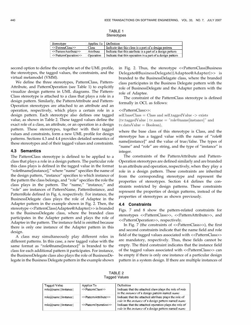
We define the three stereotypes, PatternClass, Pattern-Attribute, and PatternOperation (see Table 1) to explicitlyvisualize design patterns in UML diagrams. The Pattern-Class stereotype is attached to a class that plays a role in adesign pattern. Similarly, the PatternAttribute and Pattern-Operation stereotypes are attached to an attribute and anoperation, respectively, which plays a certain role in adesign pattern. Each stereotype also defines one taggedvalue, as shown in Table 2. These tagged values define theexact role of a class, an attribute, or an operation in a designpattern. These stereotypes, together with their taggedvalues and constraints, form a new UML profile for designpatterns. Sections 4.3 and 4.4 provides detailed semantics ofthese stereotypes and of their tagged values and constraints.
4.3 Semantics
The PatternClass stereotype is defined to be applied to aclass that plays a role in a design pattern. The particular rolethis class plays is defined in the tagged value in the format“role@name[instance],” where “name” specifies the name ofthe design pattern, “instance” specifies to which instance ofthe pattern the class belongs, and “role” specifies the role theclass plays in the pattern. The “name,” “instance,” and“role” are instances of PatternName, PatternInstance, andPatternRole defined in Fig. 6, respectively. For instance, theBusinessDelegate class plays the role of Adaptee in theAdapter pattern in the example shown in Fig. 2. Then, thestereotype <<PatternClass{Adaptee@Adapter}>> is brandedto the BusinessDelegate class, where the branded classparticipates in the Adapter pattern and plays the role ofAdaptee in the pattern. The instance field is omitted becausethere is only one instance of the Adapter pattern in thisdesign.
A class may simultaneously play different roles indifferent patterns. In this case, a new tagged value with thesame format as “role@name[instance]” is branded to theclass for each additional pattern it participates. For instance,the BusinessDelegate class also plays the role of BusinessDe-legate in the Business Delegate pattern in the example shown
in Fig. 2. Thus, the stereotype <<PatternClass{Business
Delegate@BusinessDelegate}{Adaptee@Adapter}>> is
branded to the BusinessDelagate class, where the branded
class participates in the Business Delegate pattern with the
role of BusinessDelegate and the Adapter pattern with the
role of Adaptee.The constraint of the PatternClass stereotype is defined
formally in OCL as follows:
<<PatternClass>>:
self.baseClass = Class and self.taggedValue -> exists
(tv:taggedValue j tv.name = }role@name[instance]} and
tv.dataValue = Boolean),
where the base class of this stereotype is Class, and the
stereotype has a tagged value with the name of “role@
name[instance]” and the value of true/false. The types of
“name” and “role” are string, and the type of “instance” is
integer.The constraints of the PatternAttribute and Pattern-
Operation stereotypes are defined similarly and are branded
to an attribute and operation, respectively, when they play a
role in a design pattern. These constraints are inherited
from the corresponding stereotype and represent the
properties of stereotypes. Section 4.4 defines the con-
straints restricted by design patterns. These constraints
represent the properties of design patterns, instead of the
properties of stereotypes as shown previously.
4.4 Constraints
Figs. 7 and 8 show the pattern-related constraints for
stereotypes <<PatternClass>>, <<PatternAttribute>>, and
<<PatternOperation>>, respectively.In Fig. 7 (the constraints of <<PatternClass>>), the first
and second constraints indicate that the name field and role
field of the tagged values associated with <<PatternClass>>
are mandatory, respectively. Thus, these fields cannot be
empty. The third constraint indicates that the instance field
of the tagged values associated with <<PatternClass>> can
be empty if there is only one instance of a particular design
pattern in a system design. If there are multiple instances of
440 IEEE TRANSACTIONS ON SOFTWARE ENGINEERING, VOL. 33, NO. 7, JULY 2007
TABLE 2Tagged Values
TABLE 1Stereotypes
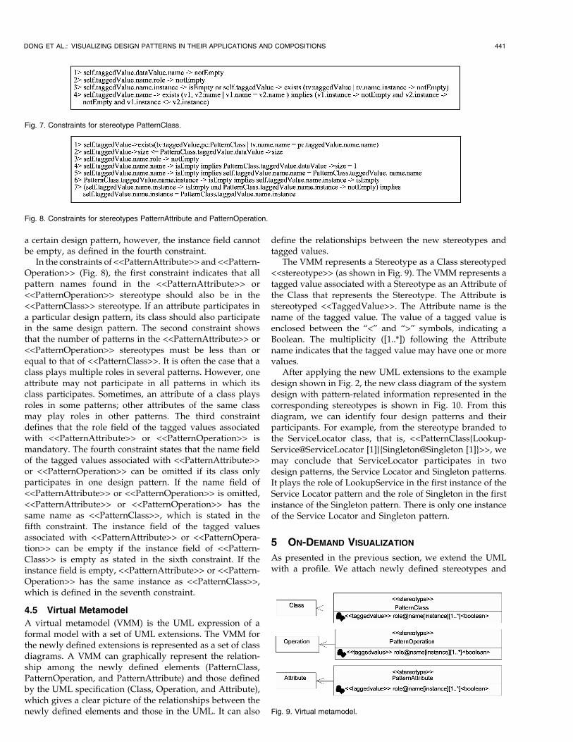
a certain design pattern, however, the instance field cannotbe empty, as defined in the fourth constraint.
In the constraints of <<PatternAttribute>> and <<Pattern-Operation>> (Fig. 8), the first constraint indicates that allpattern names found in the <<PatternAttribute>> or<<PatternOperation>> stereotype should also be in the<<PatternClass>> stereotype. If an attribute participates ina particular design pattern, its class should also participatein the same design pattern. The second constraint showsthat the number of patterns in the <<PatternAttribute>> or<<PatternOperation>> stereotypes must be less than orequal to that of <<PatternClass>>. It is often the case that aclass plays multiple roles in several patterns. However, oneattribute may not participate in all patterns in which itsclass participates. Sometimes, an attribute of a class playsroles in some patterns; other attributes of the same classmay play roles in other patterns. The third constraintdefines that the role field of the tagged values associatedwith <<PatternAttribute>> or <<PatternOperation>> ismandatory. The fourth constraint states that the name fieldof the tagged values associated with <<PatternAttribute>>or <<PatternOperation>> can be omitted if its class onlyparticipates in one design pattern. If the name field of<<PatternAttribute>> or <<PatternOperation>> is omitted,<<PatternAttribute>> or <<PatternOperation>> has thesame name as <<PatternClass>>, which is stated in thefifth constraint. The instance field of the tagged valuesassociated with <<PatternAttribute>> or <<PatternOpera-tion>> can be empty if the instance field of <<Pattern-Class>> is empty as stated in the sixth constraint. If theinstance field is empty, <<PatternAttribute>> or <<Pattern-Operation>> has the same instance as <<PatternClass>>,which is defined in the seventh constraint.
4.5 Virtual Metamodel
A virtual metamodel (VMM) is the UML expression of aformal model with a set of UML extensions. The VMM forthe newly defined extensions is represented as a set of classdiagrams. A VMM can graphically represent the relation-ship among the newly defined elements (PatternClass,PatternOperation, and PatternAttribute) and those definedby the UML specification (Class, Operation, and Attribute),which gives a clear picture of the relationships between thenewly defined elements and those in the UML. It can also
define the relationships between the new stereotypes andtagged values.
The VMM represents a Stereotype as a Class stereotyped<<stereotype>> (as shown in Fig. 9). The VMM represents atagged value associated with a Stereotype as an Attribute ofthe Class that represents the Stereotype. The Attribute isstereotyped <<TaggedValue>>. The Attribute name is thename of the tagged value. The value of a tagged value isenclosed between the “<” and “>” symbols, indicating aBoolean. The multiplicity ([1..*]) following the Attributename indicates that the tagged value may have one or morevalues.
After applying the new UML extensions to the exampledesign shown in Fig. 2, the new class diagram of the systemdesign with pattern-related information represented in thecorresponding stereotypes is shown in Fig. 10. From thisdiagram, we can identify four design patterns and theirparticipants. For example, from the stereotype branded tothe ServiceLocator class, that is, <<PatternClass{Lookup-Service@ServiceLocator [1]}{Singleton@Singleton [1]}>>, wemay conclude that ServiceLocator participates in twodesign patterns, the Service Locator and Singleton patterns.It plays the role of LookupService in the first instance of theService Locator pattern and the role of Singleton in the firstinstance of the Singleton pattern. There is only one instanceof the Service Locator and Singleton pattern.
5 ON-DEMAND VISUALIZATION
As presented in the previous section, we extend the UMLwith a profile. We attach newly defined stereotypes and
DONG ET AL.: VISUALIZING DESIGN PATTERNS IN THEIR APPLICATIONS AND COMPOSITIONS 441
Fig. 9. Virtual metamodel.
Fig. 7. Constraints for stereotype PatternClass.
Fig. 8. Constraints for stereotypes PatternAttribute and PatternOperation.
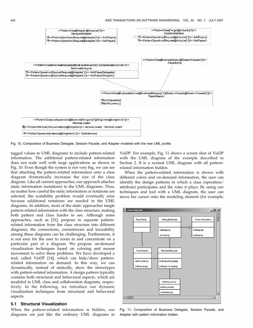
tagged values to UML diagrams to include pattern-relatedinformation. The additional pattern-related informationdoes not scale well with large applications as shown inFig. 10. Even though the system is not very big, we can seethat attaching the pattern-related information onto a classdiagram dramatically increases the size of the classdiagram. Like all current approaches, our approach attachesstatic information (notations) to the UML diagrams. Thus,no matter how careful the static information or notations areselected, the scalability problem would eventually arisebecause additional notations are needed in the UMLdiagrams. In addition, most of the static approaches tanglepattern-related information with the class structure, makingboth pattern and class harder to see. Although someapproaches, such as [31], propose to separate pattern-related information from the class structure into differentdiagrams, the connections, consistencies and traceabilityamong these diagrams can be challenging. Furthermore, itis not easy for the user to zoom in and concentrate on aparticular part of a diagram. We propose on-demandvisualization techniques based on coloring and mousemovement to solve these problems. We have developed atool, called VisDP [14], which can hide/show pattern-related information on demand. In this way, we candynamically, instead of statically, show the stereotypeswith pattern-related information. A design pattern typicallycontains both structural and behavioral aspects, which aremodeled in UML class and collaboration diagrams, respec-tively. In the following, we introduce our dynamicvisualization techniques from structural and behavioralaspects.
5.1 Structural Visualization
When the pattern-related information is hidden, ourdiagrams are just like the ordinary UML diagrams in
VisDP. For example, Fig. 11 shows a screen shot of VisDPwith the UML diagram of the example described inSection 2. It is a normal UML diagram with all pattern-related information hidden.
When the pattern-related information is shown withdifferent colors and on-demand information, the user canidentify the design patterns in which a class (operation/attribute) participates and the roles it plays. By using ourtechniques and tool with a UML diagram, the user canmove her cursor onto the modeling element (for example,
442 IEEE TRANSACTIONS ON SOFTWARE ENGINEERING, VOL. 33, NO. 7, JULY 2007
Fig. 11. Composition of Business Delegate, Session Facade, and
Adapter with pattern information hidden.
Fig. 10. Composition of Business Delegate, Session Facade, and Adapter modeled with the new UML profile.
class, operation, and attribute) in question. All the classes
that participate in the same pattern under the cursor are
changed to the same color. If the class under the cursor
participates in more than one design patterns, different
colors are used to distinguish the patterns. All pattern-
related information encoded in the stereotypes and tagged
values of a modeling element is shown when the user
moves the cursor over that modeling element. If the cursor
is over a class that participates in more than one pattern,
different colors are displayed in alternation on this class.
When the user’s cursor moves out, all pattern-related
information is gone, and no color is shown. The diagram
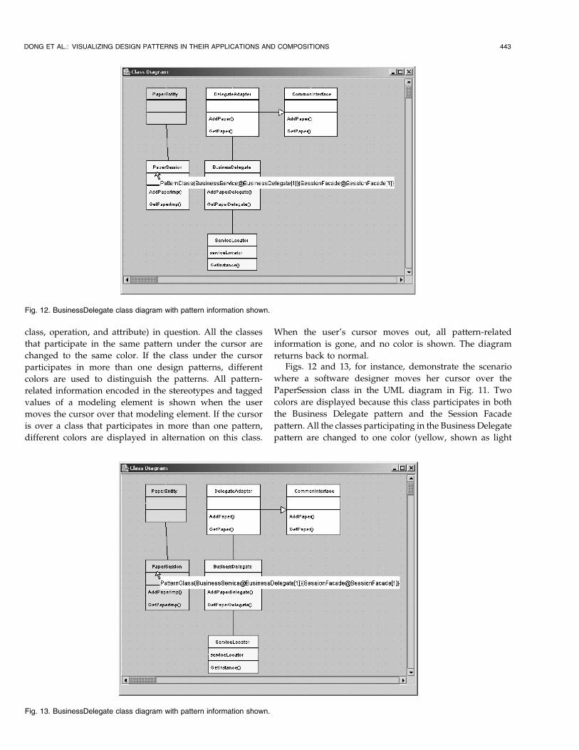
returns back to normal.Figs. 12 and 13, for instance, demonstrate the scenario
where a software designer moves her cursor over the
PaperSession class in the UML diagram in Fig. 11. Two
colors are displayed because this class participates in both
the Business Delegate pattern and the Session Facade
pattern. All the classes participating in the Business Delegate
pattern are changed to one color (yellow, shown as light
DONG ET AL.: VISUALIZING DESIGN PATTERNS IN THEIR APPLICATIONS AND COMPOSITIONS 443
Fig. 12. BusinessDelegate class diagram with pattern information shown.
Fig. 13. BusinessDelegate class diagram with pattern information shown.
gray in black-and-white print), whereas the class participat-ing in the Session Facade pattern is changed to another color(green, shown as dark gray in black-and-white print). Thecolor of the overlapping class(es) (PaperSession) is blinkingbetween yellow (for Business Delegate pattern) and green(for Session Facade pattern), as illustrated by two screenshots at two points in time in Figs. 12 and 13, respectively.Since the user’s cursor is over the class name compartmentof the PaperSession class, VisDP shows a text box containingdetailed pattern-related information described in terms ofthe stereotype and tagged values of this class. Through thestereotype and tagged values, therefore, the designer is ableto identify this class participating in both the BusinessDelegate and the Session Facade patterns. It plays the role of“Business Service” in the Business Delegate pattern and therole of “Session Facade” in the Session Facade pattern. Bothpatterns in which the BusinessDelegate class participates arethe first instances of such patterns. Suppose the designermoves the cursor down to the operation compartment of thesame class, the stereotype and tagged values of theoperation AddPaperDelegate() is displayed. All colors staythe same. When the user’s cursor moves out, all pattern-related information and colors disappear. The diagramreturns to normal, as shown in Fig. 11.
5.2 Behavioral Visualization
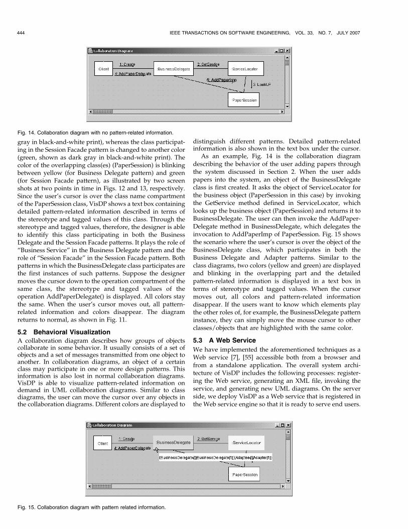
A collaboration diagram describes how groups of objectscollaborate in some behavior. It usually consists of a set ofobjects and a set of messages transmitted from one object toanother. In collaboration diagrams, an object of a certainclass may participate in one or more design patterns. Thisinformation is also lost in normal collaboration diagrams.VisDP is able to visualize pattern-related information ondemand in UML collaboration diagrams. Similar to classdiagrams, the user can move the cursor over any objects inthe collaboration diagrams. Different colors are displayed to
distinguish different patterns. Detailed pattern-relatedinformation is also shown in the text box under the cursor.
As an example, Fig. 14 is the collaboration diagramdescribing the behavior of the user adding papers throughthe system discussed in Section 2. When the user addspapers into the system, an object of the BusinessDelegateclass is first created. It asks the object of ServiceLocator forthe business object (PaperSession in this case) by invokingthe GetService method defined in ServiceLocator, whichlooks up the business object (PaperSession) and returns it toBusinessDelegate. The user can then invoke the AddPaper-Delegate method in BusinessDelegate, which delegates theinvocation to AddPaperImp of PaperSession. Fig. 15 showsthe scenario where the user’s cursor is over the object of theBusinessDelegate class, which participates in both theBusiness Delegate and Adapter patterns. Similar to theclass diagrams, two colors (yellow and green) are displayedand blinking in the overlapping part and the detailedpattern-related information is displayed in a text box interms of stereotype and tagged values. When the cursormoves out, all colors and pattern-related informationdisappear. If the users want to know which elements playthe other roles of, for example, the BusinessDelegate patterninstance, they can simply move the mouse cursor to otherclasses/objects that are highlighted with the same color.
5.3 A Web Service
We have implemented the aforementioned techniques as aWeb service [7], [55] accessible both from a browser andfrom a standalone application. The overall system archi-tecture of VisDP includes the following processes: register-ing the Web service, generating an XML file, invoking theservice, and generating new UML diagrams. On the serverside, we deploy VisDP as a Web service that is registered inthe Web service engine so that it is ready to serve end users.
444 IEEE TRANSACTIONS ON SOFTWARE ENGINEERING, VOL. 33, NO. 7, JULY 2007
Fig. 14. Collaboration diagram with no pattern-related information.
Fig. 15. Collaboration diagram with pattern related information.
On the client side, the user may use any common UML
tools, such as Rational Rose, to draw diagrams with
stereotypes and tagged values representing pattern-related
information as introduced in Section 4. When the user
wants to use the VisDP Web service to visualize pattern-
related information encapsulated in the diagrams, she may
use an appropriate plug-in (for example, UniSys XMI [54]
for Rational Rose) to transform a UML diagram into an
XML file. The JavaServer Pages (JSP) page [54] of VisDP
takes the XML file as an input and returns the user a Java
applet with a new UML diagram that displays design
patterns on demand as shown previously. There are several
advantages of the architecture of VisDP. First, it works with
current UML tools, not only Rational Rose, as long as a
corresponding plug-in can generate the XML files of the
UML diagrams. Second, new services can be provided, for
example, for visualizing UML diagrams other than classand collaboration diagrams that have been visualized inVisDP. Third, our service can be used anywhere andanytime [54].
5.4 A Conference Management System
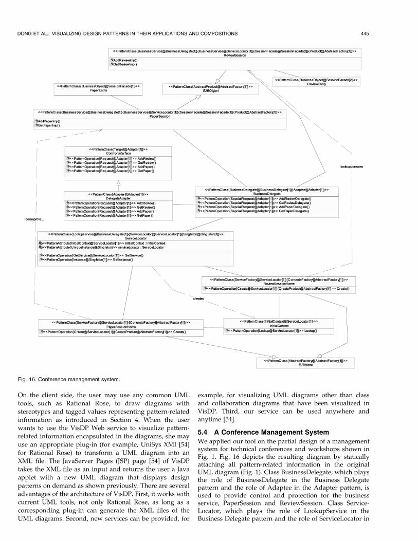
We applied our tool on the partial design of a managementsystem for technical conferences and workshops shown inFig. 1. Fig. 16 depicts the resulting diagram by staticallyattaching all pattern-related information in the originalUML diagram (Fig. 1). Class BusinessDelegate, which playsthe role of BusinessDelegate in the Business Delegatepattern and the role of Adaptee in the Adapter pattern, isused to provide control and protection for the businessservice, PaperSession and ReviewSession. Class Service-Locator, which plays the role of LookupService in theBusiness Delegate pattern and the role of ServiceLocator in
DONG ET AL.: VISUALIZING DESIGN PATTERNS IN THEIR APPLICATIONS AND COMPOSITIONS 445
Fig. 16. Conference management system.
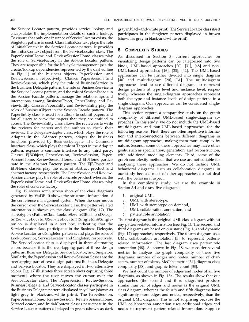
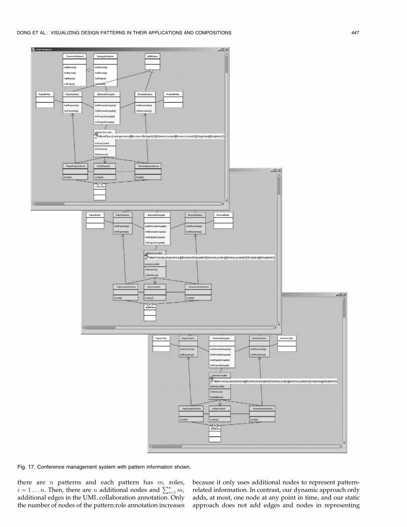
the Service Locator pattern, provides service lookup andencapsulates the implementation details of such a lookup.To ensure that only one instance of ServiceLocator exists, theSingleton pattern is used. Class InitialContext plays the roleof InitialContext in the Service Locator pattern. It providesthe InitialContext object from the ServiceLocator class. ThePaperSessionHome and ReviewSessionHome classes playthe role of ServiceFactory in the Service Locator pattern.They are responsible for the life-cycle management (see thecreate/lookup dependencies represented by the dashed linein Fig. 1) of the business objects, PaperSession, andReviewSession, respectively. Classes PaperSession andReviewSession, which play the role of BusinessService inthe Business Delegate pattern, the role of BusinessService inthe Service Locator pattern, and the role of SessionFacade inthe Session Facade pattern, manage the relationships andinteractions among BusinessObject, PaperEntity, and Re-viewEntity. Classes PaperEntity and ReviewEntity play theroles of BusinessObject in the Session Facade pattern. ThePaperEntity class is used for authors to submit papers andfor all users to view the papers that they are entitled toaccess. The ReviewEntity class allows the reviewers to writethe reviews for papers and the authors to check theirreviews. The DelegateAdapter class, which plays the role ofAdapter in the Adapter pattern, adapts the businessfunctions provided by BusinessDelegate. The Common-Interface class, which plays the role of Target in the Adapterpattern, exposes a common interface to any third party.Classes EJBObject, PaperSession, ReviewSession, Paper-SessionHome, ReviewSessionHome, and EJBHome partici-pate in the Abstract Factory pattern. The EJBObject andEJBHome classes play the roles of abstract product andabstract factory, respectively. The PaperSession and Review-Session classes play the roles of concrete product, whereas thePaperSessionHome and ReviewSessionHome classes playthe roles of concrete factory.
Fig. 17 shows some screen shots of the class diagramsgenerated by VisDP. It shows the structural information ofthe conference management system. When the user movesthe cursor over the ServiceLocator class, the pattern-relatedinformation is shown on the class diagram (Fig. 17). Thestereotype <<PatternClass{LookupService@BusinessDelega-te}{ServiceLocator@ServiceLocator}{Singleton@Single-ton}>> is displayed in a text box, indicating that theServiceLocator class participates in the Business Delegate,Service Locator, and Singleton patterns, and plays the roles ofLookupService, ServiceLocator, and Singleton, respectively.The ServiceLocator class is displayed in three alternatingcolors because it is the overlapping part of three designpatterns, Business Delegate, Service Locator, and Singleton.Similarly, the PaperSession and ReviewSession classes are theoverlapping part of two design patterns: Business Delegateand Service Locator. They are displayed in two alternativecolors. Fig. 17 illustrates three screen shots capturing threemoments where the user moves the cursor over theServiceLocator class. The PaperSession, ReviewSession,BusinessDelegate, and ServiceLocator classes participate inthe Business Delegate pattern displayed in yellow (shown aslight gray in black-and-white print). The PaperSession,PaperSessionHome, ReviewSession, ReviewSessionHome,ServiceLocator, and InitialContext classes participate in theService Locator pattern displayed in green (shown as dark
gray in black-and-white print). The ServiceLocator class itselfparticipates in the Singleton pattern displayed in brown(shown as gray in black-and-white print).
6 COMPLEXITY STUDIES
As discussed in Section 3, current approaches onvisualizing design patterns can be categorized into twokinds, UML-based approaches [20], [31], [48] and non-UML-based approaches [16], [33], [42]. The UML-basedapproaches can be further divided into single diagram[48] and multidiagram [20], [31]. The multidiagramapproaches tend to use different diagrams to representdesign patterns at type level and instance level, respec-tively, whereas the single-diagram approaches representboth the type and instance levels of design patterns in asingle diagram. Our approaches can be considered single-diagram approaches.
This section reports a comparative study on the graphcomplexity of different UML-based single-diagram ap-proaches. In this study, we do not include the UML-basedmultidiagram and non-UML-based approaches for thefollowing reasons: First, there are often repetitive informa-tion and interconnections between different diagrams inmultidiagram approaches, making them more complex bynature. Second, some of these approaches may have othergoals, such as specification, generation, and reconstruction,with additional modeling elements. Third, some of thegraph complexity methods that we use are not suitable foranalyzing these approaches. We do not include UMLbehavioral diagrams such as collaboration diagrams inour study because most of other approaches do not dealwith the behavioral aspect.
In this complexity study, we use the example inSection 5.4 and draw five diagrams:
1. original UML,2. UML with stereotype,3. UML with stereotype on demand,4. UML collaboration annotation, and5. pattern:role annotation.
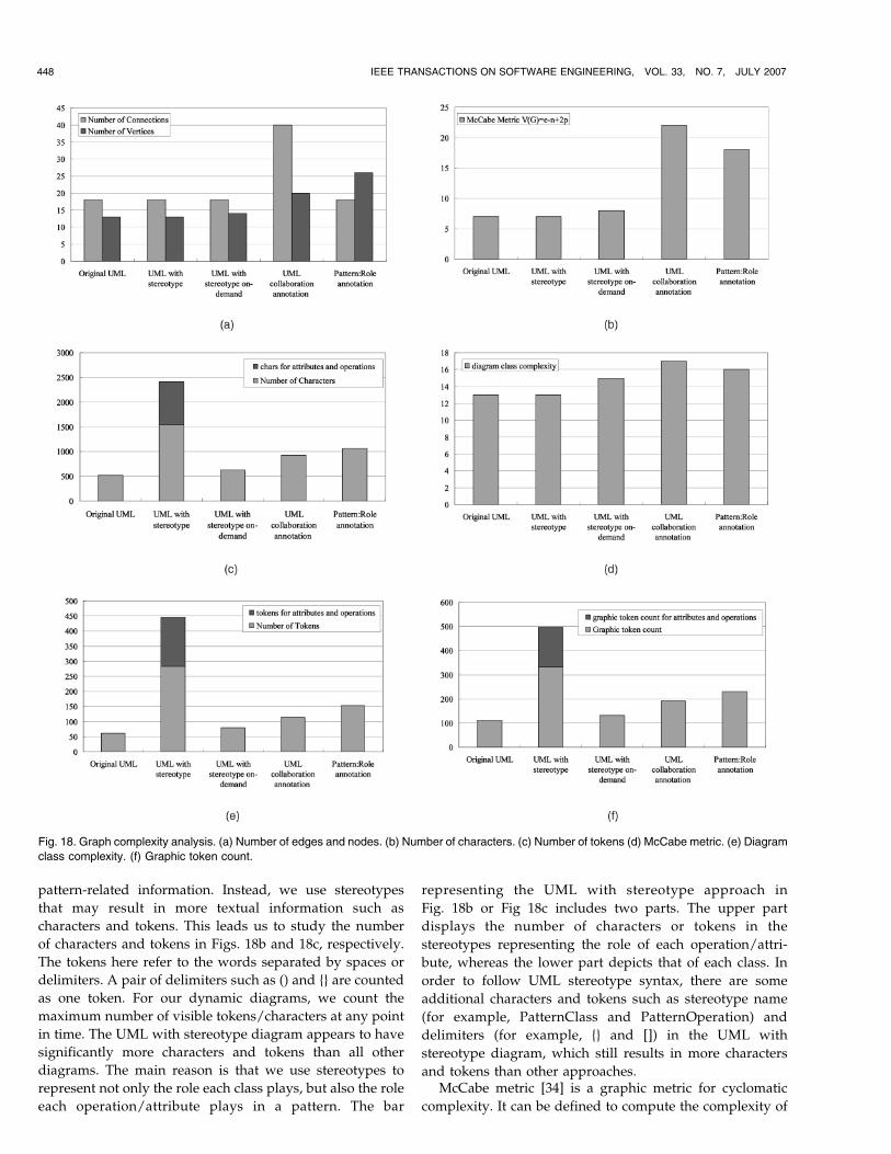
The first diagram is the original UML class diagram withoutany pattern-related information (see Fig. 1). The second andthird diagrams are based on our static (Fig. 16) and dynamic(Fig. 17) approaches, respectively. The fourth diagram usesUML collaboration annotation [5] to represent pattern-related information. The last diagram uses pattern:roleannotation [48]. As shown in Fig. 18, we consider severalmetrics to analyze the graph complexity of these fivediagrams: number of edges and nodes, number of char-acters, number of tokens, McCabe metric [34], diagram classcomplexity [38], and graphic token count [38].
We first count the number of edges and nodes of all fivediagrams, as shown in Fig. 18a. The results show that ourapproaches (the second and third diagrams) producesimilar number of edges and nodes as the original UMLclass diagram, whereas the fourth and fifth diagrams havesignificantly more edges and nodes, respectively, than theoriginal UML diagram. This is not surprising because theUML collaboration annotation uses additional edges andnodes to represent pattern-related information. Suppose
446 IEEE TRANSACTIONS ON SOFTWARE ENGINEERING, VOL. 33, NO. 7, JULY 2007
there are n patterns and each pattern has mi roles,i ¼ 1 . . .n. Then, there are n additional nodes and
Pni¼1 mi
additional edges in the UML collaboration annotation. Onlythe number of nodes of the pattern:role annotation increases
because it only uses additional nodes to represent pattern-related information. In contrast, our dynamic approach onlyadds, at most, one node at any point in time, and our staticapproach does not add edges and nodes in representing
DONG ET AL.: VISUALIZING DESIGN PATTERNS IN THEIR APPLICATIONS AND COMPOSITIONS 447
Fig. 17. Conference management system with pattern information shown.
pattern-related information. Instead, we use stereotypes
that may result in more textual information such as
characters and tokens. This leads us to study the number
of characters and tokens in Figs. 18b and 18c, respectively.
The tokens here refer to the words separated by spaces or
delimiters. A pair of delimiters such as () and {} are counted
as one token. For our dynamic diagrams, we count the
maximum number of visible tokens/characters at any point
in time. The UML with stereotype diagram appears to have
significantly more characters and tokens than all other
diagrams. The main reason is that we use stereotypes to
represent not only the role each class plays, but also the role
each operation/attribute plays in a pattern. The bar
representing the UML with stereotype approach in
Fig. 18b or Fig 18c includes two parts. The upper part
displays the number of characters or tokens in the
stereotypes representing the role of each operation/attri-
bute, whereas the lower part depicts that of each class. In
order to follow UML stereotype syntax, there are some
additional characters and tokens such as stereotype name
(for example, PatternClass and PatternOperation) and
delimiters (for example, {} and []) in the UML with
stereotype diagram, which still results in more characters
and tokens than other approaches.McCabe metric [34] is a graphic metric for cyclomatic
complexity. It can be defined to compute the complexity of
448 IEEE TRANSACTIONS ON SOFTWARE ENGINEERING, VOL. 33, NO. 7, JULY 2007
Fig. 18. Graph complexity analysis. (a) Number of edges and nodes. (b) Number of characters. (c) Number of tokens (d) McCabe metric. (e) Diagram
class complexity. (f) Graphic token count.
a graph in the following way: For a graph G with n nodes,e edges, and p connected components, vðGÞ ¼ e� nþ 2p.McCabe metric tends to compute the graphic complexitybased on the numbers of the edges and nodes. We calculatethe McCabe metric of all five diagrams. Fig. 18d shows thatboth the UML collaboration annotation and the pattern:roleannotation render the diagrams with significantly higherMcCabe complexity. This result converges with the one ofthe number of edges and nodes in Fig. 18a.
The diagram class metric characterizes the complexity ofthe class of diagrams being created. In this metric, not onlyedges and nodes are considered, but also labels areincluded. In contrast to previous metrics, this one takesinto account the types of edges, nodes, and labels, instead ofthe numbers of them. An edge of different type from otheredges uses some visual attribute or appendage such as lineweight, fill pattern (dotted versus dashed), arrowhead type,arrow tail type, or color. A node is of different graphic typeby means of some visual attribute such as shape, color, fillpattern, or size. The type of a label differs from othersthrough graphic attribute such as font, font weight, size, orcapitalization. The diagram class complexity can becomputed as
Diagram Class Complexity =
number of node types + number of edge types
+ number of label types:
We compute the diagram class complexity of all fivediagrams with the result shown in Fig. 18e. Because all theapproaches add only a few new types of edges, nodes, andlabels, their diagrams are not significantly more complex thanthe original UML diagram. Only the diagram with UMLcollaboration annotation is slightly more complex than allother diagrams in terms of diagram class metric.
The graphic token count is a measure of graph complex-ity by counting the total number of all the nodes, edges, andlabels in a diagram. If a node contains another node, there isa containment relationship. Thus, an implicit edge iscounted for such containment relationship. If a node isdirectly adjoined to another node, there is an adjoinmentrelationship causing an implicit edge to be counted. Labelsare text, whose count is done according to the rules oftextual token counting. The graphic token count complexitycan be computed:
Graphic token count =
number of nodes + number of edges + textual token count +
number of containment + number of adjoinments.
This metric considers labels, as well as nodes and edges,and treats a textual token with the same complexity as anode or edge. Fig. 18f shows the complexity of all fivediagrams in terms of this metric. The UML with stereotypeappears to be significantly more complex than otherapproaches. As discussed previously, the main reason isthat we use stereotypes to represent operation/attributeroles, as well as class roles in a pattern, which increases thecomplexity of the diagram. If we remove the stereotypes ofoperation/attribute roles as shown in the upper part of the
bar of UML with stereotype, then the remaining becomescloser to other approaches.
In summary, our UML with stereotype approach is lesscomplex than other approaches in the complexity metrics ifnot considering the number of characters or tokens. Overall,our dynamic approach (UML with stereotype on demand)is less complex than or equal to other approaches in allgraphic complexity metrics discussed previously. Ourmeasurement of the complexity metrics are mostly basedon the number of nodes and edges, which belong to thecategory of geometrical complexity [10]. According to [10],the simpler a diagram geometrically, the easier it can beunderstood.
7 CASE STUDY
In this section, we study the Java.awt package from JDKversion 1.4. It consists of 485 classes stored in 345 files. Thetotal number of classes includes inner and anonymousclasses in the package. The total number of lines of the codeis 142.8 KLOC. The main goal of this case study is toevaluate the scalability of our approach and tool in thecontext of a widely used real-world application. To evaluatethe scalability, we use existing tools such as Rational Rose torecover the design of the Java.awt package from its sourcecode. A snapshot of the reverse-engineering result is shownin Fig. 19. Due to the large size of the class diagram, onlypart of the design of Java.awt is shown in the figure. Otherparts of the design may be viewed by moving the horizontaland vertical scroll bars. Inner and anonymous classes in thepackage are not shown.
Based on the recent work on reverse-engineering designpatterns from Java.awt, in particular, the result in [39], wemanually add the stereotypes of pattern-related informationin the class diagram of Java.awt. Niere et al. [39] havestudied the Java.awt package and identified four designpatterns, one instance of the Strategy pattern, one instanceof the Composite pattern, and two instances of the Bridgepattern. In addition to their discovery using their tool, wemanually identified some more design patterns in theJava.awt package as shown in Table 3. The first four designpattern instances, Strategy[1], Composite[1], Bridge[1], andBridge[2], are discovered automatically in [39], whereas thelast three pattern instances, Bridge[3], Adapter[1], andAdapter[2], are through our manual discovery. The leftcolumn in Table 3 lists the names of the design patterns andtheir corresponding instance indices in the design. Theinstance indices are put into the angle brackets followingthe pattern names. The middle column in Table 3 lists theroles in the corresponding patterns in the left column. Theright column lists the Java.awt classes that play thecorresponding roles in the middle column of the corre-sponding patterns in the left column. For instance, the firstinstance of the Bridge pattern in Table 3 has three roles:Abstraction, Implementor, and ConcreteImplementor. TheContainer class from Java.awt plays the role of Abstraction.The LayoutManager class plays the role of Implementor,whereas the FlowLayout and GridLayout classes play therole of ComcreteImplementor in the Bridge pattern.
We manually add all the information related to theseseven pattern instances in the class diagram of Java.awtbased on our UML profile. We then use the UniSys plug-in[54] to generate the XMI file as the input to our VisDP tool.Our tool returns a Java applet, as shown in Fig. 20, which is
DONG ET AL.: VISUALIZING DESIGN PATTERNS IN THEIR APPLICATIONS AND COMPOSITIONS 449
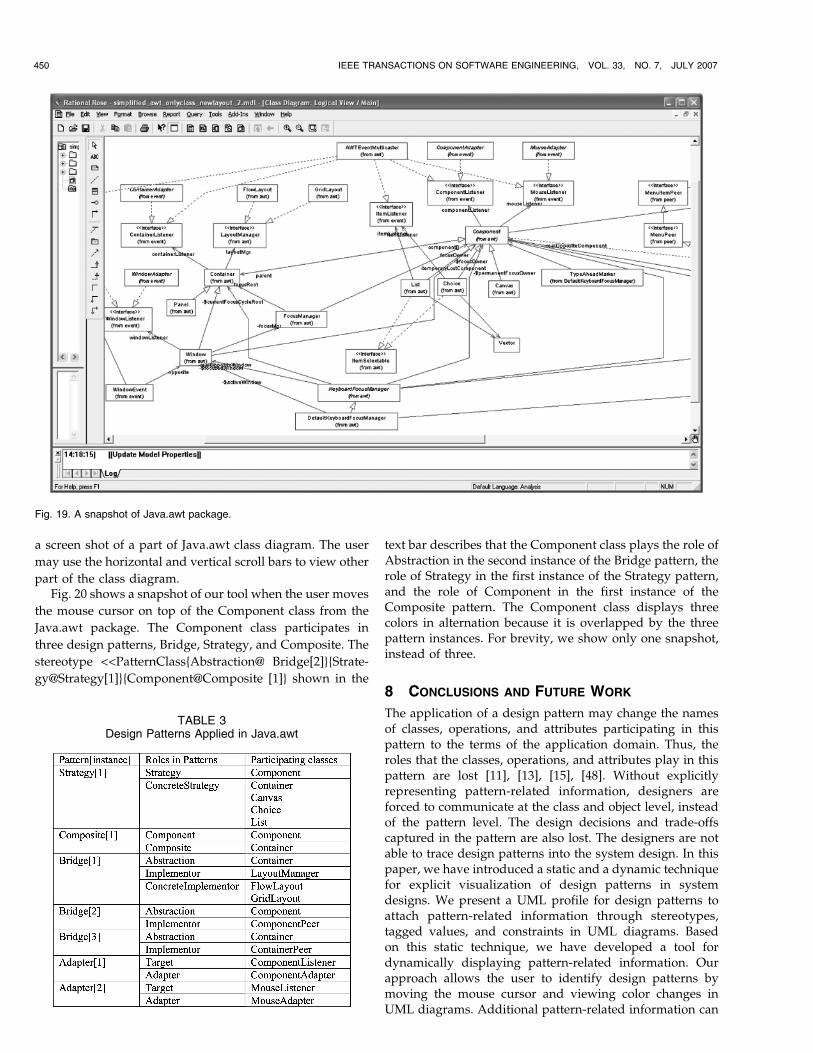
a screen shot of a part of Java.awt class diagram. The user
may use the horizontal and vertical scroll bars to view other
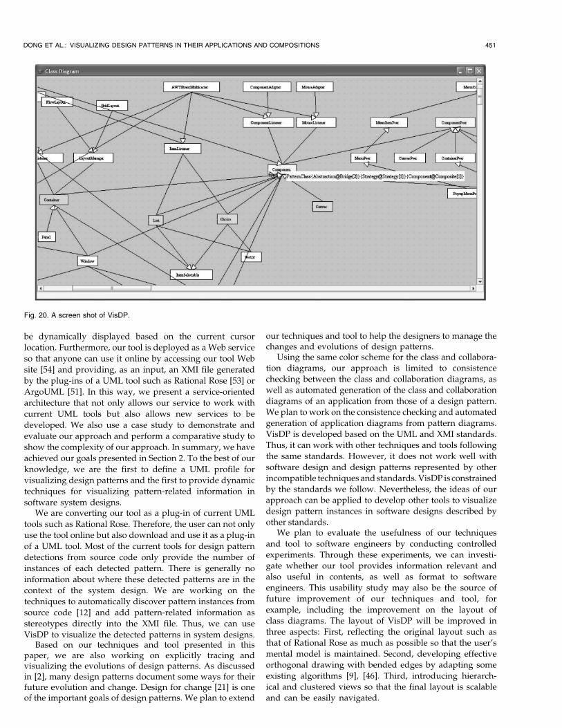
part of the class diagram.Fig. 20 shows a snapshot of our tool when the user moves
the mouse cursor on top of the Component class from the
Java.awt package. The Component class participates in
three design patterns, Bridge, Strategy, and Composite. The
stereotype <<PatternClass{Abstraction@ Bridge[2]}{Strate-
gy@Strategy[1]}{Component@Composite [1]} shown in the
text bar describes that the Component class plays the role ofAbstraction in the second instance of the Bridge pattern, therole of Strategy in the first instance of the Strategy pattern,and the role of Component in the first instance of theComposite pattern. The Component class displays threecolors in alternation because it is overlapped by the threepattern instances. For brevity, we show only one snapshot,instead of three.
8 CONCLUSIONS AND FUTURE WORK
The application of a design pattern may change the namesof classes, operations, and attributes participating in thispattern to the terms of the application domain. Thus, theroles that the classes, operations, and attributes play in thispattern are lost [11], [13], [15], [48]. Without explicitlyrepresenting pattern-related information, designers areforced to communicate at the class and object level, insteadof the pattern level. The design decisions and trade-offscaptured in the pattern are also lost. The designers are notable to trace design patterns into the system design. In thispaper, we have introduced a static and a dynamic techniquefor explicit visualization of design patterns in systemdesigns. We present a UML profile for design patterns toattach pattern-related information through stereotypes,tagged values, and constraints in UML diagrams. Basedon this static technique, we have developed a tool fordynamically displaying pattern-related information. Ourapproach allows the user to identify design patterns bymoving the mouse cursor and viewing color changes inUML diagrams. Additional pattern-related information can
450 IEEE TRANSACTIONS ON SOFTWARE ENGINEERING, VOL. 33, NO. 7, JULY 2007
Fig. 19. A snapshot of Java.awt package.
TABLE 3Design Patterns Applied in Java.awt
be dynamically displayed based on the current cursor
location. Furthermore, our tool is deployed as a Web service
so that anyone can use it online by accessing our tool Web
site [54] and providing, as an input, an XMI file generated
by the plug-ins of a UML tool such as Rational Rose [53] or
ArgoUML [51]. In this way, we present a service-oriented
architecture that not only allows our service to work with
current UML tools but also allows new services to be
developed. We also use a case study to demonstrate and
evaluate our approach and perform a comparative study to
show the complexity of our approach. In summary, we have
achieved our goals presented in Section 2. To the best of our
knowledge, we are the first to define a UML profile for
visualizing design patterns and the first to provide dynamic
techniques for visualizing pattern-related information in
software system designs.We are converting our tool as a plug-in of current UML
tools such as Rational Rose. Therefore, the user can not only
use the tool online but also download and use it as a plug-in
of a UML tool. Most of the current tools for design pattern
detections from source code only provide the number of
instances of each detected pattern. There is generally no
information about where these detected patterns are in the
context of the system design. We are working on the
techniques to automatically discover pattern instances from
source code [12] and add pattern-related information as
stereotypes directly into the XMI file. Thus, we can use
VisDP to visualize the detected patterns in system designs.Based on our techniques and tool presented in this
paper, we are also working on explicitly tracing andvisualizing the evolutions of design patterns. As discussedin [2], many design patterns document some ways for theirfuture evolution and change. Design for change [21] is oneof the important goals of design patterns. We plan to extend
our techniques and tool to help the designers to manage thechanges and evolutions of design patterns.
Using the same color scheme for the class and collabora-
tion diagrams, our approach is limited to consistence
checking between the class and collaboration diagrams, as
well as automated generation of the class and collaboration
diagrams of an application from those of a design pattern.
We plan to work on the consistence checking and automated
generation of application diagrams from pattern diagrams.
VisDP is developed based on the UML and XMI standards.
Thus, it can work with other techniques and tools following
the same standards. However, it does not work well with
software design and design patterns represented by other
incompatible techniques and standards. VisDP is constrained
by the standards we follow. Nevertheless, the ideas of our
approach can be applied to develop other tools to visualize
design pattern instances in software designs described by
other standards.We plan to evaluate the usefulness of our techniques
and tool to software engineers by conducting controlled
experiments. Through these experiments, we can investi-
gate whether our tool provides information relevant and
also useful in contents, as well as format to software
engineers. This usability study may also be the source of
future improvement of our techniques and tool, for
example, including the improvement on the layout of
class diagrams. The layout of VisDP will be improved in
three aspects: First, reflecting the original layout such as
that of Rational Rose as much as possible so that the user’s
mental model is maintained. Second, developing effective
orthogonal drawing with bended edges by adapting some
existing algorithms [9], [46]. Third, introducing hierarch-
ical and clustered views so that the final layout is scalable
and can be easily navigated.
DONG ET AL.: VISUALIZING DESIGN PATTERNS IN THEIR APPLICATIONS AND COMPOSITIONS 451
Fig. 20. A screen shot of VisDP.
ACKNOWLEDGMENTS
The authors would like to thank the anonymous reviewers
for their constructive and insightful comments that have
helped them to improve the presentation significantly.
REFERENCES
[1] P. Alencar, D. Cowan, and C. Lucena, “A Formal Approach toArchitectural Design Patterns,” Proc. Third Int’l Symp. FormalMethods Europe, pp. 576-594, 1996.
[2] P. Alencar, D. Cowan, J. Dong, and C. Lucena, “A Pattern-BasedApproach to Structural Design Composition,” Proc. IEEE 23rdAnn. Int’l Computer Software and Applications Conf. (COMPSAC ’99),pp. 160-165, Oct. 1999.
[3] D. Alur, J. Crupi, and D. Malks, Core J2EE Patterns: Best Practicesand Design Strategies. Sun Microsystems, 2001.
[4] S. Berner, M. Glinz, and S. Joos, “A Classification of Stereotypesfor Object-Oriented Modeling Languages,” Proc. Second Int’l Conf.Unified Modeling Language (UML ’99), pp. 249-264, Oct. 1999.
[5] G. Booch, J. Rumbaugh, and I. Jacobson, The Unified ModelingLanguage User Guide. Addison-Wesley, 1999.
[6] F. Buschmann, R. Meunier, H. Rohnert, P. Sommerlad, and M.Stal, Pattern-Oriented Software Architecture: A System of Patterns.John Wiley & Sons, 1996.
[7] E. Cerami, Web Services Essentials. O’Reilly and Assoc., 2002.[8] J.O. Coplien and D.C. Schmidt, Pattern Languages of Program
Design. Addison-Wesley, 1995.[9] G. Di Battista, P. Eades, R. Tamassia, and I.G. Tollis, Graph
Drawing: Algorithms for the Visualization of Graphs. Prentice Hall,1999.
[10] C. Ding and P. Mateti, “A Framework for the Automated Drawingof Data Structure Diagrams,” IEEE Trans. Software Eng., vol. 16,no. 5, May 1990.
[11] J. Dong, “Adding Pattern Related Information in Structural andBehavioral Diagrams,” Information and Software Technology (IST),vol. 46, no. 5, pp. 293-300, Apr. 2004.
[12] J. Dong, D.S. Lad, and Y. Zhao, “DP-Miner: Design PatternDiscovery Using Matrix,” Proc. 14th Ann. IEEE Int’l Conf. Eng.Computer-Based Systems (ECBS ’07), pp. 371-380, Mar. 2007.
[13] J. Dong and S. Yang, “Visualizing Design Patterns with a UMLProfile,” Proc. IEEE Symp. Human Centric Computing Language andEnvironments, pp. 123-125, Oct. 2003.
[14] J. Dong, S. Yang, and K. Zhang, “VisDP: A Web Service forVisualizing Design Patterns on Demand,” Proc. IEEE Int’l Conf.Information Technology Coding and Computing (ITCC ’05), pp. 385-391, Apr. 2005.
[15] J. Dong and K. Zhang, Design Pattern Compositions in UML.Software Visualization—From Theory to Practice. Kluwer Academic,pp. 287-308, 2003.
[16] A.H. Eden, J. Gil, and A. Yehudai, “Precise Specification andAutomatic Application of Design Patterns,” Proc. 12th IEEE Int’lAutomated Software Eng. Conf., pp. 143-152, Nov. 1997.
[17] G. Florijn, M. Meijers, and P. van Winsen, “Tool Support forObject-Oriented Patterns,” Proc. European Conf. Object-OrientedProgramming, pp. 472-495, 1997.
[18] M. Fontoura, W. Pree, and B. Rumpe, “UML-F: A ModelingLanguage for Object-Oriented Frameworks,” Proc. European Conf.Object-Oriented Programming (ECOOP ’00), pp. 63-82, July 2000.
[19] M. Fowler, Analysis Patterns: Reusable Object Models. Addison-Wesley, 1997.
[20] R.B. France, D. Kim, S. Ghosh, and E. Song, “A UML-BasedPattern Specification Technique,” IEEE Trans. Software Eng.,vol. 30, no. 3, Mar. 2004.
[21] E. Gamma, R. Helm, R. Johnson, and J. Vlissides, Design Patterns,Elements of Reusable Object-Oriented Software. Addison-Wesley,1995.
[22] G.C. Gannod and B.H.C. Cheng, “A Framework for Classifyingand Comparing Software Reverse Engineering and DesignRecovery Techniques,” Proc. Working Conf. Reverse Eng., F. Balmas,M. Blaha, and S. Rugaber, eds., pp. 77-88, 1999.
[23] Y.-G. Gueheneuc, K. Mens, and R. Wuyts, “A ComparativeFramework for Design Recovery Tools,” Proc. Conf. SoftwareMaintenance and Reeng. (CSMR ’06), 2006.
[24] Y. Gueheneuc, H. Sahraoui, and F. Zaidi, “Fingerprinting DesignPatterns,” Proc. 11th Working Conf. Reverse Eng. (WCRE ’04), 2004.
[25] J.H. Hausmann, R. Heckel, and S. Sauer, “Towards Dynamic MetaModeling of UML Extensions: An Extensible Semantics for UMLSequence Diagrams,” Proc. 2001 IEEE Symp. Human-CentricComputing Languages and Environments, pp. 80-87, Sept. 2001.
[26] D. Heuzeroth, T. Holl, and W. Lowe, “Combining Static andDynamic Analyses to Detect Interaction Patterns,” Proc. Sixth Int’lConf. Integrated Design and Process Technology (IDPT ’02), June 2002.
[27] M.M. Kande and A. Strohmeier, “Towards a UML Profile forSoftware Architecture Descriptions,” Proc. Unified ModelingLanguage, pp. 513-527, 2000.
[28] R. Keller, R. Schauer, S. Robitalille, and P. Page, “Pattern-BasedReverse-Engineering of Design Components,” Proc. 21st Int’l Conf.Software Eng., pp. 226-235, May 1999.
[29] C. Kramer and L. Prechelt, “Design Recovery by AutomatedSearch for Structural Design Patterns in Object-Oriented Soft-ware,” Proc. Working Conf. Reverse Eng., Nov. 1996.
[30] S. Lahtinen and J. Peltonen, “Enhancing Usability of UML CASE-Tools with Speech Recognition,” Proc. 2003 IEEE Symp. Human-Centric Computing Languages and Environments, pp. 227-235, Oct.2003.
[31] A. Lauder and S. Kent, “Precise Visual Specification of DesignPatterns,” Proc. European Conf. Object-Oriented Programming,pp. 114-134, 1998.
[32] A. LeGuennec, G. Sunye, and J. Jezequel, “Precise Modeling ofDesign Patterns,” Proc. Third Int’l Conf. Unified Modeling Language,pp. 482-496, Oct. 2000.
[33] D. Mapdlsden, J. Hosking, and J. Grundy, “Design PatternModelling and Instantiation Using DPML,” Proc. 40th Int’l Conf.Object-Oriented Languages and Systems (TOOLS Pacific ’02), 2002.
[34] T. McCabe, “A Software Complexity Measure,” IEEE Trans.Software Eng., vol. 2, no. 6, pp. 308-320, Dec. 1976.
[35] N. Medvidovic, D.S. Rosenblum, D.F. Redmiles, and J.E. Robbins,“Modeling Software Architectures in the Unified ModelingLanguage,” ACM Trans. Software Eng. and Methodology, vol. 11,no. 1, pp. 2-57, Jan. 2002.
[36] Y. Medynskiy, N. Ducheneaut, and A. Farahat, “Using HybridNetworks for the Analysis of Online Software DevelopmentCommunities,” Proc. ACM Int’l Conf. Human Factors in ComputingSystems (CHI ’06), pp. 513-516, Apr. 2006.
[37] T. Mikkonen, “Formalizing Design Pattern,” Proc. 20th Int’l Conf.Software Eng., pp. 115-124, 1998.
[38] J.V. Nickerson, “Visual Programming,” PhD dissertation, NewYork Univ., 1994.
[39] J. Niere, W. Schafer, J.P. Wadsack, L. Wendehals, and J. Welsh,“Towards Pattern-Based Design Recovery,” Proc. 24th Int’l Conf.Software Eng., pp. 338-348, 2002.
[40] J. Peltonen and P. Selonen, “Processing UML Models with VisualScripts,” Proc. 2001 IEEE Symp. Human-Centric Computing Lan-guages and Environments, pp. 264-271, Sept. 2001.
[41] W. Pree, Design Patterns for Object-Oriented Software Development.Addison-Wesley, 1995.
[42] S.P. Reiss, “Working with Patterns and Codes,” Proc. 33rd HawaiiInt’l Conf. System Sciences, 2000.
[43] J. Rumbaugh, I. Jacobson, and G. Booch, The Unified ModelingLanguage Reference Manual. Addison-Wesley, 1999.
[44] S. Sauer and G. Engels, “UML-Based Behavior Specification ofInteractive Multimedia Applications,” Proc. 2001 IEEE Symp.Human-Centric Computing Languages and Environments, pp. 248-255, Sept. 2001.
[45] T. Schafer, M. Eichberg, M. Haupt, and M. Menzini, “TheSEXTANT Software Exploration Tool,” IEEE Trans. SoftwareVisualization, vol. 32, no. 9, pp. 753-768, Sept. 2006.
[46] J.M. Six, “Vistool: A Tool for Visualizing Graphs,” PhD disserta-tion, Univ. of Texas at Dallas, Oct. 2000.
[47] G. Sunye, A. LeGuennec, and J. Jezequel, “Design PatternsApplication in UML,” Proc. European Conf. Object-OrientedProgramming, pp. 44-62, 2000.
[48] J. Vlissides, “Notation, Notation, Notation,” C++ Report, Apr.1998.
[49] G. Wagner, “A UML Profile for Agent-Oriented Modeling,” Proc.Third Int’l Workshop Agent-Oriented Software Eng., July 2002.
[50] J.B. Warmer and A.G. Kleppe, The Object Constraint Language:Precise Modeling with UML. Addison-Wesley, 1998.
[51] ArgoUML, http://argouml.tigris.org/, 2006.[52] Object Management Group, Unified Modeling Language Specifica-
tion Version 1.4, http://www.omg.org, 2001.
452 IEEE TRANSACTIONS ON SOFTWARE ENGINEERING, VOL. 33, NO. 7, JULY 2007
[53] IBM Rational Rose, http://www.ibm.com/software/rational/,2006.
[54] VisDP, http://www.utdallas.edu/~jdong/VisDP, 2007.[55] “Web Services Architecture Requirements,” W3C Working Draft
14, http://www.w3.org, Nov. 2002.
Jing Dong received the BS degree in computerscience from Peking University in 1992 and theMMath and PhD degrees in computer sciencefrom the University of Waterloo, Canada, in 1997and 2002, respectively. He is an assistantprofessor in the Department of ComputerScience at the University of Texas at Dallas.His research and teaching interests includeformal and automated methods for softwareengineering, software modeling and design,
service-oriented architecture, and visualization. He is a member of theIEEE, IEEE Computer Society, and the ACM.
Sheng Yang received the BE degree fromTsinghua University in 1994 and the MS andPhD degrees in computer science from theUniversity of Texas at Dallas in 2001 and2006, respectively. His research interests in-clude automated software engineering methods,model-driven architecture, software evolutionand analysis, and software engineering toolsand environment. He is an architect/lead en-gineer in a cutting-edge mobile entertainment
company in Silicone Valley. His role in the company is to lead thearchitecture and design of the entire platform. He is also remotelymanaging a team of software engineers in China. He is a member of theIEEE.
Kang Zhang received the BEng degree incomputer engineering from the University ofElectronic Science and Technology, China, in1982 and the PhD degree from the University ofBrighton, UK, in 1990. He is a professor ofcomputer science and the director of the VisualComputing Lab at the University of Texas atDallas. He previously held academic positions inChina, the UK, and Australia. His researchinterests include visual languages, information
visualization, and their applications in software engineering and Webengineering. He has had more than 150 publications in these areas (seehttp://www.utdallas.edu/~kzhang). He is a senior member of the IEEE.
. For more information on this or any other computing topic,please visit our Digital Library at www.computer.org/publications/dlib.
DONG ET AL.: VISUALIZING DESIGN PATTERNS IN THEIR APPLICATIONS AND COMPOSITIONS 453


![Generation of Kandinsky Art - University of Texas at Dallas › ~kzhang › Publications › ... · the most successful computer-generated art forms has been fractal art [3]. According](https://img.pdfslide.us/doc/110x75/5f15c0eecbb7bf6c6911748e/generation-of-kandinsky-art-university-of-texas-at-dallas-a-kzhang-a-publications.jpg)


![\documentstyle[11pt]{article} - The University of …kzhang/Publications/pub.doc · Web viewGenerating and Adjusting Web Sub-Graph Displays for Web Navigation, in M. Mohammadian (Ed.)](https://img.pdfslide.us/doc/110x75/5d45fa4088c9930e7e8e02d3/documentstyle11ptarticle-the-university-of-kzhangpublicationspubdoc.jpg)