Embed Size (px)
Citation preview
IEEE TRANSACTIONS ON CLOUD COMPUTING, VOL. XX, NO. X, MONTH YEAR 1
Failure Aware Semi-Centralized Virtual NetworkEmbedding in Cloud Computing Fat-Tree Data
Center NetworksChinmaya Kumar Dehury, Member, IEEE , Prasan Kumar Sahoo, Senior Member, IEEE
Abstract— In Cloud Computing, the tenants opting for the Infrastructure as a Service (IaaS) send the resource requirements to theCloud Service Provider (CSP) in the form of Virtual Network (VN) consisting of a set of inter-connected Virtual Machines (VM).Embedding the VN onto the existing physical network is known as Virtual Network Embedding (VNE) problem. One of the majorresearch challenges is to allocate the physical resources such that the failure of the physical resources would bring less impact ontothe users’ service. Additionally, the major challenge is to handle the embedding process of growing number of incoming users’ VNsfrom the algorithm design point-of-view. Considering both of the above-mentioned research issues, a novel Failure awareSemi-Centralized VNE (FSC-VNE) algorithm is proposed for the Fat-Tree data center network with the goal to reduce the impact of theresource failure onto the existing users. The impact of failure of the Physical Machines (PMs), physical links and network devices aretaken into account while allocating the resources to the users. The beauty of the proposed algorithm is that the VMs are assigned todifferent PMs in a semi-centralized manner. In other words, the embedding algorithm is executed by multiple physical servers in orderto concurrently embed the VMs of a VN and reduces the embedding time. Extensive simulation results show that the proposedalgorithm can outperform over other VNE algorithms.
Index Terms—Cloud computing, Virtual Network Embedding (VNE), Fat-Tree data center, resource mapping.
F
1 INTRODUCTION
V IRTUALIZATION is the key technology that enablesInfrastructure Provider (IP) to share the same physical
servers or Physical Machines (PMs) among multiple tenantsby creating virtual version of the resources such as storage,memory, CPU and network. This allows the system devel-oper to decouple the service instances from the underlinehardware resources by placing the virtualization softwarebetween the user’s operating system and the underlinedphysical resources [1]. On the other hand, a large numberof PMs in a data center is connected through several typesof switches and long cables. Fat-Tree [2] network topologyis widely used in commercial data centers in order to es-tablish the connection among PMs through core switches,aggregation switches and edge switches as the basic con-necting devices. The resources of the PMs are provided tothe tenants by creating multiple Virtual Machines (VMs),ensuring the basic privacy properties, better QoS and otheruser requirements as mentioned at the time of Service LevelAgreement (SLA) establishment between the tenant and theIP [3].
The network of multiple VMs that are requested bythe cloud users is called Virtual Network (VN). The jobof the Cloud Service Provider (CSP) is to provide a set ofinterconnected PMs onto which the VN can be embedded,
Chinmaya Kumar Dehury was with the department of Computer Scienceand Information Engineering, Chang Gung University, Guishan, Taiwan.Currently, he is with the Mobile & Cloud Lab, Institute of Computer Science,University of Tartu, Estonia. Email: [email protected] Kumar Sahoo (Corresponding Author) is with Department of Com-puter Science and Information Engineering, Chang Gung University, Taiwan.He is an Adjunct Research Fellow in the Division of Colon and RectalSurgery, Chang Gung Memorial Hospital, Linkou, Taiwan. Email: [email protected]
which is known as Virtual Network Embedding (VNE)problem [4]. This problem can also be relate to the problemof virtual network function placement [5]. The job of virtualnetwork embedding is to embed VMs and virtual links. VMembedding refers to as selecting a suitable PM by takinglocation, energy and users’ budget constraint parametersinto consideration [6]. Virtual link embedding refers to asfinding the shortest path between the corresponding PMstaking number of switches, load on the physical links,latency and several other parameters into consideration.
The unexpected failure of resources is one of the majorresearch issues that cannot be ignored by the cloud serviceprovider. Failure in resources has a direct impact on theservices. Service failures have direct impact on QoS, energyconsumption, SLA violation, and huge revenue loss of CSP[7]. One of the major research issues in VNE is how toavoid the unexpected service failures due to the failureof any hardware module or software module. The failureof resources includes switch failure, physical link failure,and PM failure [8]. The major reasons behind the resourcefailures could be the wrong input to the user program, highworkload on switches and PMs and failure of power supply.It is reported that a single failure (or cloud outage) forone hour could bring more than $336,000 financial loss tocloud providers, such as Amazon and Microsoft [9], [10].The impact of the potential failure of any physical resourceon service availability, productivity, business reputation, etc.[11] must be analyzed before embedding the VN onto thephysical network. Here, we are considering the failure ofPM, the physical network link and the switches. The VMsof the incoming VN must be distributed in such a way thatimpact of physical resource failure is minimized by avoiding
arX
iv:2
111.
0272
7v1
[cs
.DC
] 4
Nov
202
1
IEEE TRANSACTIONS ON CLOUD COMPUTING, VOL. XX, NO. X, MONTH YEAR 2
potential resource failure. It is also essential to design analgorithm that can embed the VNs considering the failureimpact of the physical resources. An efficient VNE algo-rithm may consume significant time only for the embeddingpurpose. The nature of the algorithm such as centralized,distributed or semi-centralized also plays a major role inmaking embedding process faster, resulting in better QoS.
In general, the VNE algorithm is installed in a ded-icated server to accomplish the embedding process withthe responsibility to embed all incoming VNs onto thephysical network in a centralized manner. The major flawsof the centralized embedding algorithms are poor scala-bility, lower capital message, single point of failure andhigher embedding cost [12]. On the contrary, distributedembedding algorithm reduces the embedding cost and de-lay time, which occurs due to the arrival of a large numberof simultaneous VNs, but does not obtain the global viewof the physical network. As distributed VNE algorithmsare scalable unlike the centralized one, they give betterperformance as compared to the centralized approaches inthe geo-distributed Data Centers (DCs) [12]. Despite severaladvantages of the distributed VNE algorithms, obtainingan optimal embedding solution without global view of theDC network incurs heavy resource requirement and timeconsumption. To overcome the disadvantages of the cen-tralized and distributed VNE algorithms, a semi-centralizedalgorithm may produce a near-optimal embedding solutionby considering the global view of the DC network andalso can embed multiple VNs in parallel. The entire semi-centralized algorithm is divided into two sub-algorithms,which may run in two stages. If the centralized approachis followed by one sub-algorithm in the first stage, thedistributed approach is followed by another sub-algorithmin the second stage. However, if the distributed approach isfollowed in the first stage, the centralized approach will befollowed in the second stage. Multiple constraints such asrevenue maximization, guaranteeing SLA with higher QoSand power consumption maximization need to be taken intoconsideration while designing an efficient semi-centralizedVNE algorithm.
1.1 Motivation
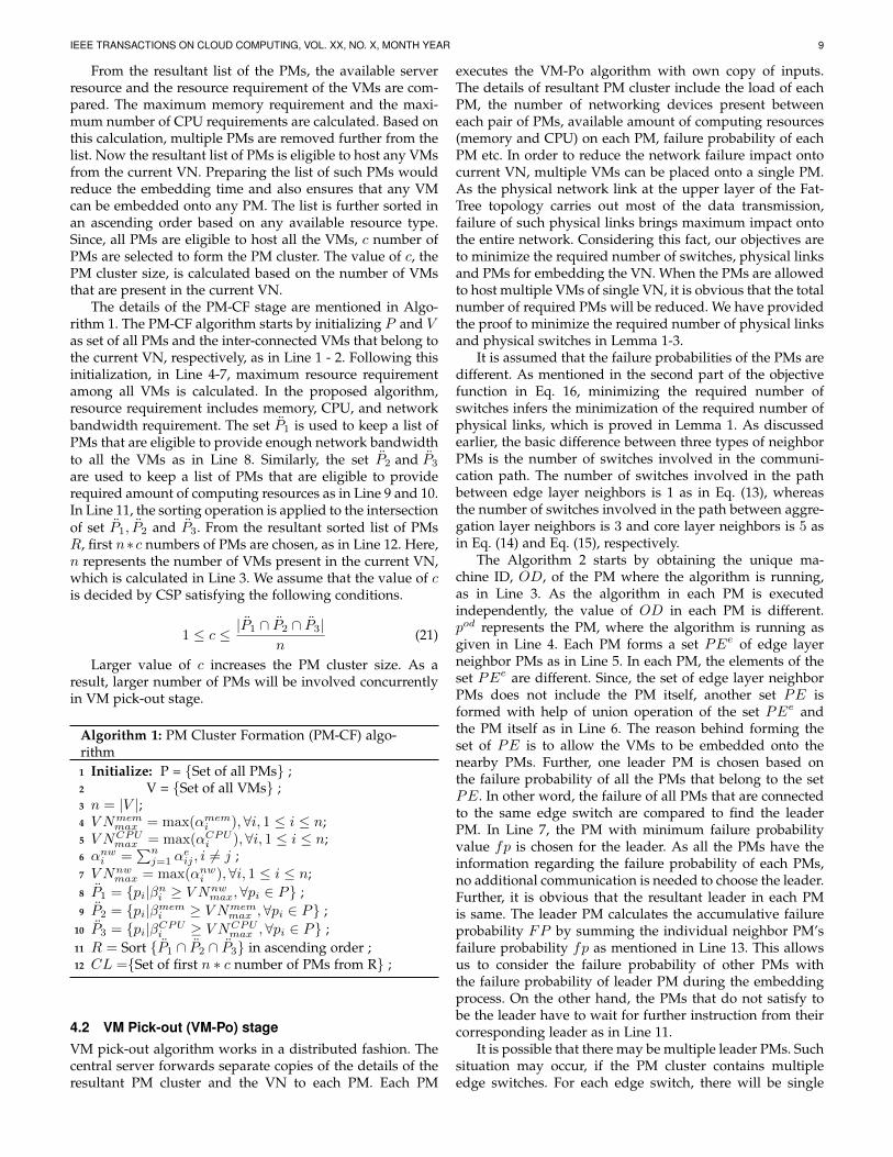
As discussed before, VNE problem refers to as embeddingof VN onto a set of interconnected PMs. In the process ofembedding, CSP needs to consider multiple factors suchas resource availability of the PMs, bandwidth availability,utilization of the resources, load balancing among all thePMs, energy consumption of the PMs, network latency etc.Failure probability of the PMs is one of the main factors,which plays a crucial role in the process of embedding.Without considering the PMs’ failure probability, CSP mayembed the VMs onto the PMs that are most likely to fail inthe next time instance. Failure of PMs results in failure ofcorresponding VMs. As a result, the corresponding serviceswould be interrupted, which may bring a huge monetaryloss for the CSP. Though a number of research articleshave been proposed recently to address the VNE problemsconsidering different factors, the failure probability of thePMs and impact of resource failure onto the existing users’request has not been studied extensively.
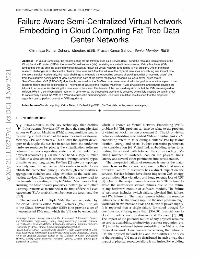
Fig. 1. Impact of resource failure on VNE.
Fig. 1 illustrates the impact of resource failure on theusers’ request. Let V N1 and V N2 be the two VNs receivedby the CSP from two different users as shown in Fig. 1(a).V N1 consists of VMs V 1, V 2, and V 3. V N2 consists of VMsV 4 and V 5. Considering the example given in Fig. 1, letthe CSP consists of two PMs PM1 and PM2 connected inFat-Tree topology with number of ports k = 2. The twoVNs V N1 and V N2 are embedded onto these two PMs.VMs V 1, V 2, and V 5 from V N1 and V N2, respectively, areembedded onto PM1. VMs V 3 and V 4 from VN V N1 andV N2, respectively, are embedded onto PM2. In this sce-nario, if physical machine PM2 is failed, it has direct impacton both users and VM V 3 and V 4 will be affected, as shownin Fig. 1(b). Besides the impact on the VMs, the virtual linkbetween VM V 3 and V 1 and the virtual link between VMV 4 and V 5 will be affected as the one of the end VMs ofthose virtual links are inactive or not in running state. Asshown in Fig. 1(c), the impact of the failure of networkresource onto the existing users is discussed. Failure of aphysical link between core switch c and aggregation switchA2 has also direct impact on all users, which can affect allfive virtual machines hosted by PM1 and PM2. Failureof this physical link also affects the virtual links (V 1, V 3)and (V 4, V 5) of V N1 and V N2, respectively. Though Fat-Tree network topology offers higher degree of fault tolerantservice through multiple physical paths between any twoservers, however in a much highly loaded network, failureof one link brings higher impact on the correspondingservers and the VMs. It is assumed that the virtual machineswithin a VN can be connected in any topology.
Further, several centralized VNE algorithms are not scal-able and are mainly designed to deploy on a single PM,which is further responsible for receiving and processing theincoming VNs [13], [14]. This centralized approach makesthe algorithm in-scalable and therefore the new VNs mayexperience delay as the single PM is busy in embeddingother VNs that arrived earlier. Here, in-scalable refers toas the lack of ability to handle the growing number ofincoming VNs to accommodate itself according to a numberof VNs. Besides, this disadvantages in-terms of in-scalabilityand the knowledge of global view of the entire physicalnetwork help the algorithm to make the most efficientembedding solution in terms of the time required to em-bed the VNs excluding the waiting time. The distributedapproach of VNE algorithm is highly scalable. Despite its
IEEE TRANSACTIONS ON CLOUD COMPUTING, VOL. XX, NO. X, MONTH YEAR 3
higher scalability nature, it is difficult to obtain an efficientembedding solution as the global view is not available forthe PMs executing the embedding algorithm. Consideringthese two traditional approaches and their disadvantages, itis essential to design a VNE algorithm, which can be highlyscalable and must consider the global view of the entirephysical network.
The above-mentioned scenario motivates us to revisit theVNE problem by taking the failure of PMs as well as thephysical links into account. Accordingly, we have proposeda novel Failure aware Semi-Centralized Virtual NetworkEmbedding (FSC-VNE) scheme with the following goals:
• To design semi-centralized VNE algorithm that canmeet the requirement of data centers with large vol-ume of requests arrival rate.
• To minimize the impact of failure of PMs and phys-ical links onto the existing users while embeddingVNs by considering the failure probability of thePMs.
The goals can be achieved by embedding the VMs ontothe PMs considering the failure probability of each PM.Further, in order to minimize the impact of physical linkfailure, multiple VMs can be embedded onto a single PM,which eventually eliminates the failure possibilities of cor-responding virtual links.
Rest of this paper is organized as follows. In Section2, we present the recent research articles related to VNE.The system model of this paper is presented in Section3. The proposed VNE algorithm is discussed in Section4. In Section 5, performance evaluation of our proposedalgorithm is made followed by the concluding remarks inSection 6.
2 RELATED WORKS
Extensive researches have been emphasized on differentaspects of VNE problem, such as energy-aware [15] lo-cation constraint [16], physical network topology [3], etc.Considering the location preferences of the users, authorsin [16], formulate the VNE problem as a graph bisectionproblem, which achieves integrated VM and virtual linkmapping. Restricting one PM to host maximum one VMin order to reduce the failure impact onto single VN arisesanother problem of accumulative failure impact onto allcorresponding VNs.
2.1 Resource utilization optimizationIn order to reduce the total amount of required physicalresources in a multi-cloud environment, priority values areassigned to the user’s requests [14]. Here, each PM can beused to host a maximum of one VM from a VN. Such anapproach contradicts the goal of minimizing the requiredphysical resources. Assigning multiple VMs onto a singlePM can effectively reduce the required amount of resources.In a likewise fashion, degree and clustering information ofa VM within a VN are used to embed the user’s requestonto physical network with the objective to minimize thenetwork utilization and maximize the acceptance ratio asin [17]. However, the dependencies among the VMs are notconsidered, resulting in inefficient mapping solution.
In a multi-service cloud environment, resource allocationand provisioning algorithms are presented in [18] consid-ering the SLA, service cost, system capacity and resourcedemand. However, considering only VM resources withoutnetwork resource may not fit into the real-life scenario.Authors in [19] propose a novel VNE algorithm consideringthe link interference due to bandwidth scarcity. The majoradvantage of the proposed I-VNE algorithm is that thetemporal and the spatial network topology information aretaken into consideration and the VNs are embedded withlow interference.
To efficiently utilize the computing resources and in-crease the acceptance ratio, authors in [6] presented a uniqueapproach to embed the VN. This is done by simply placingthe same VM onto multiple PMs and distributing the in-put data onto corresponding PMs. However, this approachrequired extra network resource and the number of PMsrequired for a VN is more than the number of VMs presentin the VN. VNF placement problem is further studied indifferent scenarios, such as 5G network slicing framework[20], Network Function Virtualization (NFV) [15]. Authorsin [21] address the Virtual Network Functions (VNFs) place-ment problem with Deep Reinforcement Learning approachto obtain a near-optimal solution. However, the proposedalgorithm does not consider the impact of the failure ofphysical resources that may bring a more significant effecton the VNFs and the resource utilization.
In federated cloud, taking minimization of the networklatency as the major goal, authors in [22] propose network-aware VNE scheme. The proposed algorithm ignores thefact that the single PM can be used to execute multipleVMs, which eventually eliminate the network resource de-mand without compromising the QoS and other user’s re-quirements. Similarly, the proposed congestion-aware VNEscheme with Hose model abstraction in [23], has the restric-tion to embed only one VM onto one PM. As a result, theopportunity to minimize the amount of required networkresource is ignored. A rank-based VNE algorithm is pre-sented in [24] considering substrate node degree, strengthand distance with others. However, its inability to scale andinability to consider the failure probability of the substratenodes and links makes the VNE approach inefficient.
2.2 Embedding time minimization
Authors in [12] propose a distributed embedding algorithm,which partitions the entire physical network into multipleblocks. Though the embedding cost for each VN is re-duced, however, the accumulative computational overheadstill exists and the total amount of required computationalresources is very high. In order to fasten the embeddingprocess for the VN that follow mess topology, authors in[25], introduced a novel approach that reduces the numberof virtual links. However, combining multiple virtual linksonto one increases the embedding cost. This trade-off isaddressed by proposing reduction algorithms. However,this centralized algorithm may not be able to scale up withthe growing number of PMs and hence may degrade theefficiency in terms of embedding time.
The VNE problem can be viewed as multi-objectivelinear programming problem, as in [26]. Though the authors
IEEE TRANSACTIONS ON CLOUD COMPUTING, VOL. XX, NO. X, MONTH YEAR 4
have achieved the goal to maximize the revenue and min-imize the embedding cost, however, the mapping solutionmay suffer from physical resource fragmentation issue andmay not produce efficient result in terms of embedding costdue to the mapping of virtual node followed by the virtuallinks.
2.3 Cost and Revenue
Two VNE algorithms are presented based on Monte Carlotree search and multi-commodity flow algorithm in [27]with the objective to maximize the profit of the IP. The pro-posed centralized VNE algorithm claims to map the virtualnodes and the virtual links without splitting the physicalpath. However, the centralized approach may produce aninefficient result in terms of embedding time. In [28], a newpath algebra strategy is proposed to embed the virtual nodesand the virtual links based on cost and revenue parameter.However, the proposed multi-staged mapping strategy mayproduce extra computational overhead, resulting higher em-bedding time.
Authors in [29] address the problem of inefficient band-width reservation due to the uncertainty. Though the pro-posed stochastic approach achieves maximizing the revenueof the CSP, however, author should also consider the failureprobability of the physical links.
A number of VNE approaches have been proposedconsidering dynamic resource requirement, topology of thedata center, energy consumption, and revenue maximiza-tion. Though the studies in current literature solve manyreal-life scenarios in cloud, to the best of our knowledgenone of the studies propose an embedding scheme, whichprocesses the VNs in semi-centralized manner to fasten theembedding process and minimizes failure impact of thephysical resources onto the existing VNs.
3 PROBLEM FORMULATION
As discussed earlier, it is the job of the CSP to create/embedmultiple interconnected VMs onto a set of suitable PMs. Inthe embedding process, the network topology plays an im-portant role as it defines the network structure and the con-nectivity of one PM with other PMs. In our study, Fat-Treenetwork topology is taken into consideration as the datacenter network topology. It is assumed that the computingand network resources of PMs and the networking devicesremain static throughout the execution of the algorithm forany particular VN. In other words, the resource capacities ofthe PMs and networking devices do not change, when theVNE allocation algorithm runs. The PMs are heterogeneousin nature. The resource requirement of the VN includesthe computing and network resource demand of VMs andvirtual links, respectively, which do not change over time.Further, the topology of the VN including the number ofVMs, virtual links, the resource demand of the VMs and thevirtual links are static and hence do not change after the VNrequest is submitted to the CSP. In further sections, we willdiscuss the network topology, the VN, and failure impact ofphysical resources onto the VNs in details. A summary ofall the notations is given in Table 1.
TABLE 1List of notations
Notation DescriptionP Set of m PMs {p1, p2, . . . , pm}S Set of s switches {S1, S2, . . . , Ss}k number of ports available at each switchV Set of n VMs {v1, v2, . . . , vn}x resource type {memory, CPU}αxi Server resource requirements of VM vi
αeij Bandwidth requirement between VM vi and vjeij The virtual link between VM vi and vjβxi Resource of type x available at PM piβni Network resource available at PM piLji 1 :if there exist a link between PM pi and switch Sj
Lij 1 :if there exist a link between switch Si and switchSj
ωij Number of switches present between PM pi and PMpj
ψi Workload on PM piαei Bandwidth requirement by VM vi
Ivs (pi) The impact of failure of PM pi onto the set of VMsκji 1 :if VM vj is assigned to PM piλqrij 1 : if the virtual link eqr is assigned to physical link
Lij or Lji
InN (zij) Impact of physical link zij failure on the set ofvirtual links
IvN (zij) Impact of physical link zij failure on the set of VMsIvw(sj) Impact of network switch, sj , failure onto the set of
VMsInw(sj) Impact of network switch, sj , failure onto the set of
virtual linksPEe(pi) Set of edge layer neighboring PMs of the PM piPEa(pi) Set of aggregation layer neighboring PMs of the PM
piPEc(pi) Set of core layer neighboring PMs of the PM pi
3.1 Fat-Tree data center network
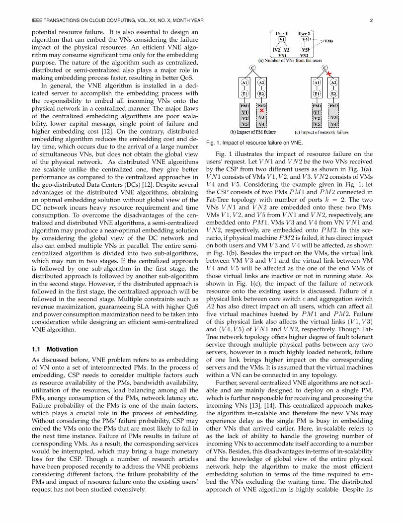
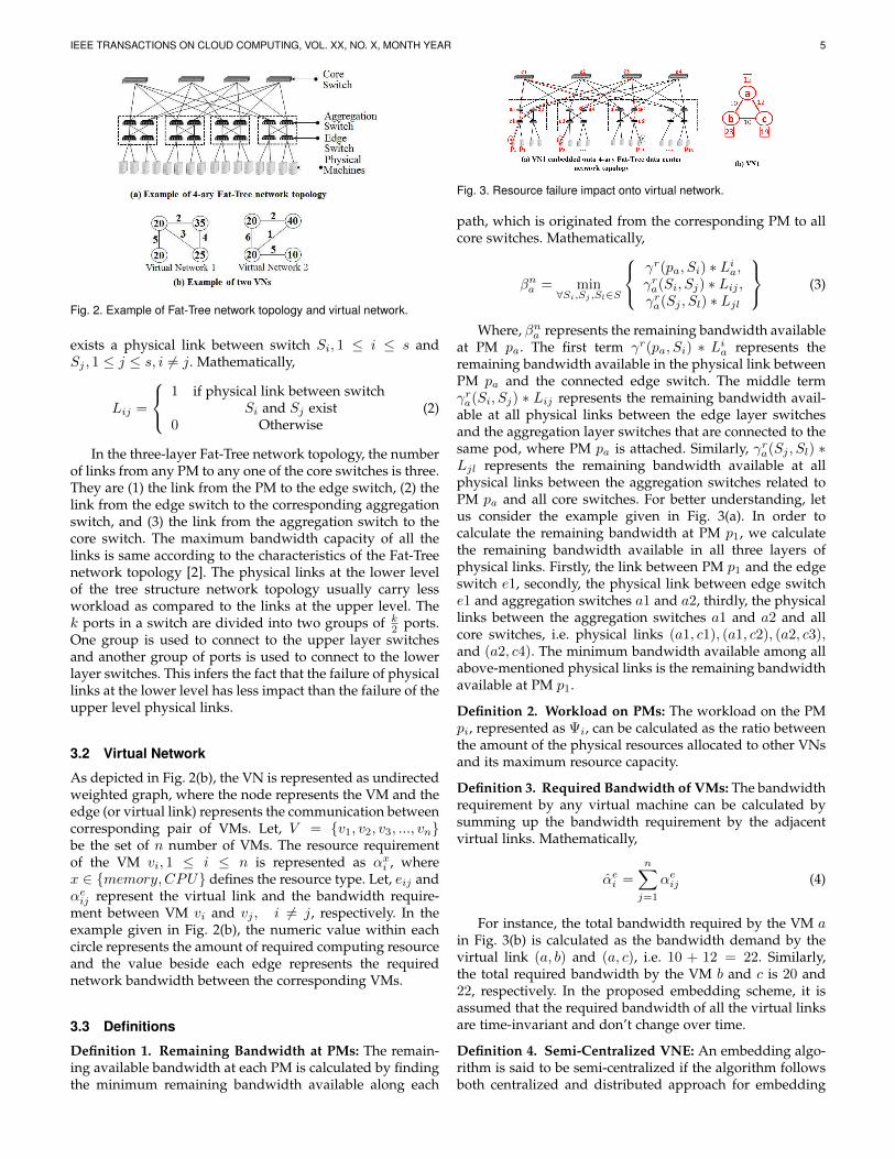
As shown in Fig. 2(a), the switches are mainly organizedinto three layers, such as core switch, aggregation switch,and edge switch in the Fat-Tree data center network [14].The number of layers in Fat-Tree can be extended to morethan three layers. However, we focus our study consideringthe basic three-layer Fat-Tree network topology. Let k bethe number of ports available at each switch. Being at theroot of the network, the number of core switches are (k2 )2.The total number of aggregation switches is equal to thetotal number of edge switches required, which is k
2 . Themaximum number of servers that can be attached to theFat-Tree topology is k3
4 . Let S = {S1, S2, S3, ..., Ss} be theset of s number of switches, which includes core switches,aggregation switches, and edge switches. The value of s canbe calculated as s = 5k2
4 .Let P = {p1, p2, p3, ..., pm} be the set of m = k3
4number of PMs that are attached to the bottom level ofFat-Tree topology. Let βxi be the resource of type x ∈{memory,CPU} available at PM pi. For instance, βmemory2
represents the amount of remaining memory available atPM p2. Lji is the boolean variable, which represents if thereexists a physical link between switch Si, 1 ≤ i ≤ s and PMpj , 1 ≤ j ≤ m. Mathematically,
Lji =
1 if physical link between PM pi
and Switch Sj exist0 Otherwise
(1)
Similarly, Lij is the boolean variable, which indicates if there
IEEE TRANSACTIONS ON CLOUD COMPUTING, VOL. XX, NO. X, MONTH YEAR 5
Fig. 2. Example of Fat-Tree network topology and virtual network.
exists a physical link between switch Si, 1 ≤ i ≤ s andSj , 1 ≤ j ≤ s, i 6= j. Mathematically,
Lij =
1 if physical link between switch
Si and Sj exist0 Otherwise
(2)
In the three-layer Fat-Tree network topology, the numberof links from any PM to any one of the core switches is three.They are (1) the link from the PM to the edge switch, (2) thelink from the edge switch to the corresponding aggregationswitch, and (3) the link from the aggregation switch to thecore switch. The maximum bandwidth capacity of all thelinks is same according to the characteristics of the Fat-Treenetwork topology [2]. The physical links at the lower levelof the tree structure network topology usually carry lessworkload as compared to the links at the upper level. Thek ports in a switch are divided into two groups of k
2 ports.One group is used to connect to the upper layer switchesand another group of ports is used to connect to the lowerlayer switches. This infers the fact that the failure of physicallinks at the lower level has less impact than the failure of theupper level physical links.
3.2 Virtual Network
As depicted in Fig. 2(b), the VN is represented as undirectedweighted graph, where the node represents the VM and theedge (or virtual link) represents the communication betweencorresponding pair of VMs. Let, V = {v1, v2, v3, ..., vn}be the set of n number of VMs. The resource requirementof the VM vi, 1 ≤ i ≤ n is represented as αxi , wherex ∈ {memory,CPU} defines the resource type. Let, eij andαeij represent the virtual link and the bandwidth require-ment between VM vi and vj , i 6= j, respectively. In theexample given in Fig. 2(b), the numeric value within eachcircle represents the amount of required computing resourceand the value beside each edge represents the requirednetwork bandwidth between the corresponding VMs.
3.3 Definitions
Definition 1. Remaining Bandwidth at PMs: The remain-ing available bandwidth at each PM is calculated by findingthe minimum remaining bandwidth available along each
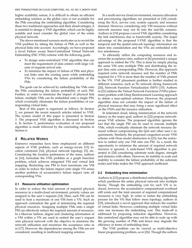
Fig. 3. Resource failure impact onto virtual network.
path, which is originated from the corresponding PM to allcore switches. Mathematically,
βna = min∀Si,Sj ,Sl∈S
γr(pa, Si) ∗ Lia,γra(Si, Sj) ∗ Lij ,γra(Sj , Sl) ∗ Ljl
(3)
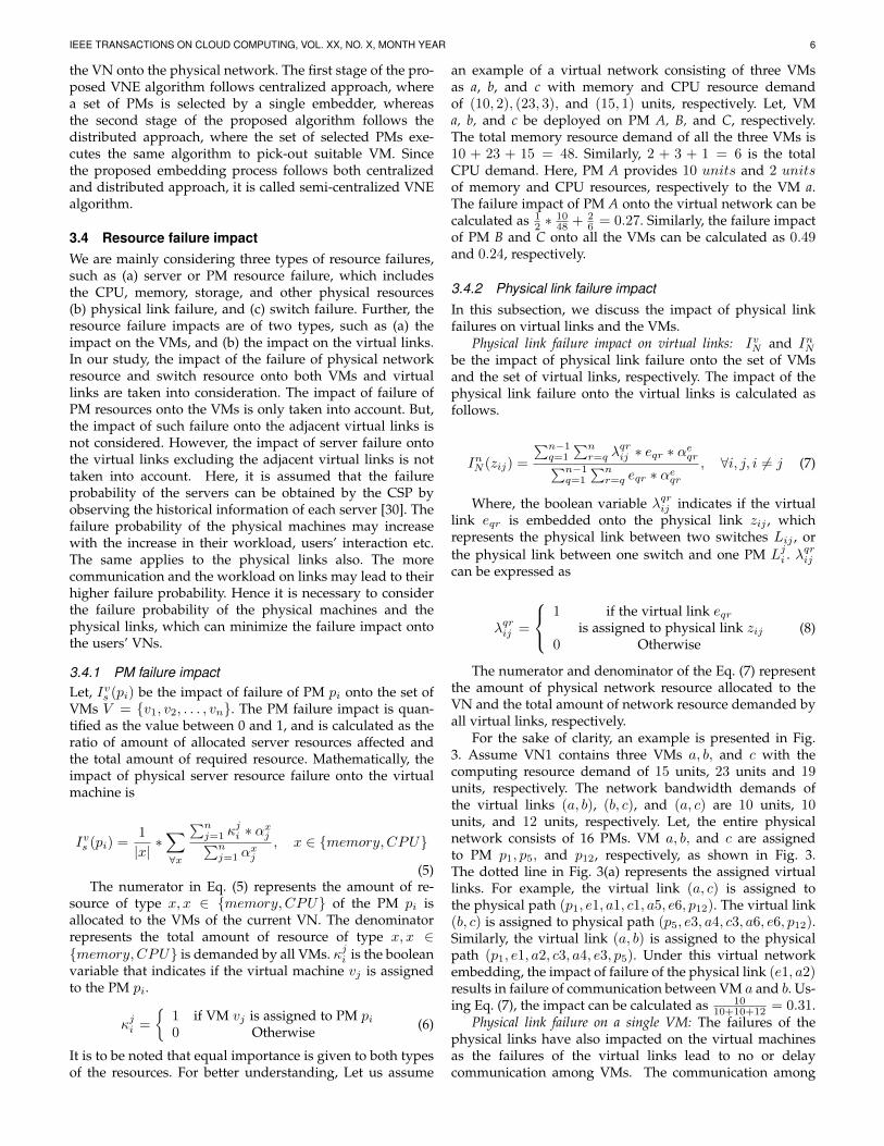
Where, βna represents the remaining bandwidth availableat PM pa. The first term γr(pa, Si) ∗ Lia represents theremaining bandwidth available in the physical link betweenPM pa and the connected edge switch. The middle termγra(Si, Sj) ∗ Lij represents the remaining bandwidth avail-able at all physical links between the edge layer switchesand the aggregation layer switches that are connected to thesame pod, where PM pa is attached. Similarly, γra(Sj , Sl) ∗Ljl represents the remaining bandwidth available at allphysical links between the aggregation switches related toPM pa and all core switches. For better understanding, letus consider the example given in Fig. 3(a). In order tocalculate the remaining bandwidth at PM p1, we calculatethe remaining bandwidth available in all three layers ofphysical links. Firstly, the link between PM p1 and the edgeswitch e1, secondly, the physical link between edge switche1 and aggregation switches a1 and a2, thirdly, the physicallinks between the aggregation switches a1 and a2 and allcore switches, i.e. physical links (a1, c1), (a1, c2), (a2, c3),and (a2, c4). The minimum bandwidth available among allabove-mentioned physical links is the remaining bandwidthavailable at PM p1.
Definition 2. Workload on PMs: The workload on the PMpi, represented as Ψi, can be calculated as the ratio betweenthe amount of the physical resources allocated to other VNsand its maximum resource capacity.
Definition 3. Required Bandwidth of VMs: The bandwidthrequirement by any virtual machine can be calculated bysumming up the bandwidth requirement by the adjacentvirtual links. Mathematically,
αei =n∑j=1
αeij (4)
For instance, the total bandwidth required by the VM ain Fig. 3(b) is calculated as the bandwidth demand by thevirtual link (a, b) and (a, c), i.e. 10 + 12 = 22. Similarly,the total required bandwidth by the VM b and c is 20 and22, respectively. In the proposed embedding scheme, it isassumed that the required bandwidth of all the virtual linksare time-invariant and don’t change over time.
Definition 4. Semi-Centralized VNE: An embedding algo-rithm is said to be semi-centralized if the algorithm followsboth centralized and distributed approach for embedding
IEEE TRANSACTIONS ON CLOUD COMPUTING, VOL. XX, NO. X, MONTH YEAR 6
the VN onto the physical network. The first stage of the pro-posed VNE algorithm follows centralized approach, wherea set of PMs is selected by a single embedder, whereasthe second stage of the proposed algorithm follows thedistributed approach, where the set of selected PMs exe-cutes the same algorithm to pick-out suitable VM. Sincethe proposed embedding process follows both centralizedand distributed approach, it is called semi-centralized VNEalgorithm.
3.4 Resource failure impactWe are mainly considering three types of resource failures,such as (a) server or PM resource failure, which includesthe CPU, memory, storage, and other physical resources(b) physical link failure, and (c) switch failure. Further, theresource failure impacts are of two types, such as (a) theimpact on the VMs, and (b) the impact on the virtual links.In our study, the impact of the failure of physical networkresource and switch resource onto both VMs and virtuallinks are taken into consideration. The impact of failure ofPM resources onto the VMs is only taken into account. But,the impact of such failure onto the adjacent virtual links isnot considered. However, the impact of server failure ontothe virtual links excluding the adjacent virtual links is nottaken into account. Here, it is assumed that the failureprobability of the servers can be obtained by the CSP byobserving the historical information of each server [30]. Thefailure probability of the physical machines may increasewith the increase in their workload, users’ interaction etc.The same applies to the physical links also. The morecommunication and the workload on links may lead to theirhigher failure probability. Hence it is necessary to considerthe failure probability of the physical machines and thephysical links, which can minimize the failure impact ontothe users’ VNs.
3.4.1 PM failure impactLet, Ivs (pi) be the impact of failure of PM pi onto the set ofVMs V = {v1, v2, . . . , vn}. The PM failure impact is quan-tified as the value between 0 and 1, and is calculated as theratio of amount of allocated server resources affected andthe total amount of required resource. Mathematically, theimpact of physical server resource failure onto the virtualmachine is
Ivs (pi) =1
|x|∗∑∀x
∑nj=1 κ
ji ∗ αxj∑n
j=1 αxj
, x ∈ {memory,CPU}
(5)The numerator in Eq. (5) represents the amount of re-
source of type x, x ∈ {memory,CPU} of the PM pi isallocated to the VMs of the current VN. The denominatorrepresents the total amount of resource of type x, x ∈{memory,CPU} is demanded by all VMs. κji is the booleanvariable that indicates if the virtual machine vj is assignedto the PM pi.
κji =
{1 if VM vj is assigned to PM pi0 Otherwise (6)
It is to be noted that equal importance is given to both typesof the resources. For better understanding, Let us assume
an example of a virtual network consisting of three VMsas a, b, and c with memory and CPU resource demandof (10, 2), (23, 3), and (15, 1) units, respectively. Let, VMa, b, and c be deployed on PM A, B, and C, respectively.The total memory resource demand of all the three VMs is10 + 23 + 15 = 48. Similarly, 2 + 3 + 1 = 6 is the totalCPU demand. Here, PM A provides 10 units and 2 unitsof memory and CPU resources, respectively to the VM a.The failure impact of PM A onto the virtual network can becalculated as 1
2 ∗1048 + 2
6 = 0.27. Similarly, the failure impactof PM B and C onto all the VMs can be calculated as 0.49and 0.24, respectively.
3.4.2 Physical link failure impactIn this subsection, we discuss the impact of physical linkfailures on virtual links and the VMs.
Physical link failure impact on virtual links: IvN and InNbe the impact of physical link failure onto the set of VMsand the set of virtual links, respectively. The impact of thephysical link failure onto the virtual links is calculated asfollows.
InN (zij) =
∑n−1q=1
∑nr=q λ
qrij ∗ eqr ∗ αeqr∑n−1
q=1
∑nr=q eqr ∗ αeqr
, ∀i, j, i 6= j (7)
Where, the boolean variable λqrij indicates if the virtuallink eqr is embedded onto the physical link zij , whichrepresents the physical link between two switches Lij , orthe physical link between one switch and one PM Lji . λ
qrij
can be expressed as
λqrij =
1 if the virtual link eqr
is assigned to physical link zij0 Otherwise
(8)
The numerator and denominator of the Eq. (7) representthe amount of physical network resource allocated to theVN and the total amount of network resource demanded byall virtual links, respectively.
For the sake of clarity, an example is presented in Fig.3. Assume VN1 contains three VMs a, b, and c with thecomputing resource demand of 15 units, 23 units and 19units, respectively. The network bandwidth demands ofthe virtual links (a, b), (b, c), and (a, c) are 10 units, 10units, and 12 units, respectively. Let, the entire physicalnetwork consists of 16 PMs. VM a, b, and c are assignedto PM p1, p5, and p12, respectively, as shown in Fig. 3.The dotted line in Fig. 3(a) represents the assigned virtuallinks. For example, the virtual link (a, c) is assigned tothe physical path (p1, e1, a1, c1, a5, e6, p12). The virtual link(b, c) is assigned to physical path (p5, e3, a4, c3, a6, e6, p12).Similarly, the virtual link (a, b) is assigned to the physicalpath (p1, e1, a2, c3, a4, e3, p5). Under this virtual networkembedding, the impact of failure of the physical link (e1, a2)results in failure of communication between VM a and b. Us-ing Eq. (7), the impact can be calculated as 10
10+10+12 = 0.31.Physical link failure on a single VM: The failures of the
physical links have also impacted on the virtual machinesas the failures of the virtual links lead to no or delaycommunication among VMs. The communication among
IEEE TRANSACTIONS ON CLOUD COMPUTING, VOL. XX, NO. X, MONTH YEAR 7
the VMs within a VN is required to finish the assignedjobs and therefore the failure of a single virtual link hasthe impact on the corresponding VMs and entire VNs [13],[30]. Following equation is used to calculate the impact ofphysical link failure onto the single VM.
IvN (zij , vq) =αeqr ∗
(αx
q∑nr=1 α
eqr
)αxq
=αeqr ∗ αxq
αxq ∗∑nr=1 α
eqr
=αeqr∑nr=1 α
eqr
, r 6= q
(9)
The notation IvN (zij , vq) represents the impact of failureof physical link zij onto the VM vq . The notation zij is usedto represent the physical link Lij or Lji . In the example givenin Fig. 3, the impact of failure of physical link (e1, a2) ontothe VM a can be calculated as 10
10+12 = 0.45.Physical link failure on all VMs: Extending further, the
impact of failure of physical link zij onto all VMs can becalculated as
IvN (zij) =n−1∑q=1
n∑r=q
λqrij
αeqr(
αxq∑n
u=1 αequ
+αx
r∑nu=1 α
eur
)∑nu=1 α
xu
,(10)
where, the numerator represents the sum of amount ofcomputing resources of two corresponding VMs of each af-fected virtual link and the denominator represents the totalamount of the resource demanded by all VMs. Applying Eq.(10) onto the example given in Fig. 3, the impact of failureof physical link (e1, a2) onto all VMs can be calculated as
1010+12 + 10
10+10 = 0.95.
3.4.3 Switch failure impactIvw and Inw be the impact of network switch failure onto theVM and the virtual link, respectively.
The failure of the switches can be considered as thecollective failure of the attached physical links. The impactof such failure onto the allocated computing resources or theVMs can be calculated by using the Eq. (10) as follows
Ivw(sj) =s∑i=1
zij ∗ IvN (zij), i 6= j (11)
Similarly, the impact of switch failure onto the allocatednetwork resources or the virtual links is calculated as fol-lows.
Inw(sj) =s∑i=1
zij ∗ InN (zij), i 6= j (12)
Considering the example given in Fig. 3, failure of theaggregation switch a4 results in failure of virtual links (a, b)and (b, c). However, failure of the core switch c1 results infailure of the virtual link (a, c).
3.5 Neighbor PMsNeighbor PMs are used to find the set PMs that are nearerto each other and can be used to embed a VN. As a result,the VMs those are belonged to the single VN are placed asnearer as possible. Neighbor PMs are of three types, such as
(a) Edge layer neighbor PMs (b) Aggregation layer neighborPMs, and (c) Core layer neighbor PMs. These are classifiedbased on the number of intermediate switches.
3.5.1 Edge layer neighbor PM
Two PMs are said to be edge layer neighbor PMs, if bothPMs are connected to the same edge switch. Mathematically,
PEe(pi) = {pj |wji = 1}, 1 ≤ i ≤ m, 1 ≤ j ≤ m, i 6= j (13)
where, PEe(pi) is the set of edge layer of neighboring PMsof the physical machine pi. w
ji is the minimum number of
intermediate switches present in between the PM pi and pj .
3.5.2 Aggregation layer neighbor PM
Two PMs are said to be aggregation layer neighbor PMs,if both PMs are attached to the same pod. In other words,the number of intermediate switches between both PMs is3. Mathematically,
PEa(pi) = {pj |wji = 3}, 1 ≤ i ≤ m, 1 ≤ j ≤ m, i 6= j (14)
where, PEa(pi) is the set of aggregation layer neighbor-ing PMs of physical machine pi.
3.5.3 Core layer neighbor PM
Similar to edge layer and aggregation layer neighbors, thenumber of intermediate switches among core layer neighborPMs is 5. This can be represented mathematically as follows.
PEc(pi) = {pj |wji = 5}, 1 ≤ i ≤ m, 1 ≤ j ≤ m, i 6= j (15)
3.6 Objective function
In the proposed failure-aware VNE scheme, the failure prob-abilities of the physical machines are taken into considera-tion in order to reduce the failure impact on the users’ VNs.The failure impact of the physical machines, physical linksand switches are considered as calculated in Section 3.4. Thefailure impact onto the VMs and virtual links are calculatedin a balanced model presuming that all the VMs and virtuallinks are not associated with any additional parameter todecide their importance. However, the VM or virtual linkhaving higher resource demand has direct influence over thefailure impact. In other word, VM having higher resourcehas maximum failure impact and similarly, the virtual linkhaving higher network resource demand has maximumfailure impact. The main goal of the proposed work is toreduce the failure impact onto the users’ VN. This is doneby embedding the VMs onto the PMs in close proximity asdiscussed above. As a result, along with the overall reducedfailure impact, the proposed VNE scheme would be able tominimize the total amount of physical resources. Based onthe above problem description, the objective function of theproposed scheme is formulated as follows:Objective:
IEEE TRANSACTIONS ON CLOUD COMPUTING, VOL. XX, NO. X, MONTH YEAR 8
minm∑i=1
[ε1 ∗ Ivs (pi) + ε2 ∗
∑∀r
IvN (Zir) + InN (Zir)
2
+ε3 ∗∑∀q
Ivw(Sq) + Inw(Sq)
2
(16)
Constraints:
αxj ≤ βxi , ∀vj ∈ V,∀pi ∈ P, x ∈ {CPU,Memory} (17)
αj ≤ βni , ∀vj ∈ V,∀pi ∈ P (18)
m∑i=1
κji = 1, ∀vj ∈ V (19)
ε1 + ε2 + ε3 = 1, 0 < ε1, ε2, ε3 < 1 (20)
The objective function in Eq. 16 is of two-fold. The firstpart focuses on selecting the PM such that its failure wouldbring minimum overall impact onto the assigned VN. Thesecond part focuses on selecting the adjacent physical linksand the switches such that their failure would bring mini-mum impact onto the virtual machines and the virtual links.The weight of the impact of the resources can be decidedby modifying the values of ε1, ε1, and ε3. This wouldallow the CSP to give importance to different resources atdifferent time instances. For example, higher value of ε2gives maximum importance to the impact of the physicallink failure over the failure of the physical machines andswitches. Similarly, equal of all the weight factors give equalimportance to the impact of failure of the PMs, physicallinks, and switches.
While evaluating the objective function, the proposedalgorithm must ensure that following constraints are sat-isfied. Constraint (17) ensures that the available computingresource of the selected physical machine is more than thecomputing resource demand of the virtual machine. Simi-larly, Constraint (18) ensures that the total required networkbandwidth of a VM is less than the available bandwidth ofthe PM. Constraint (19) ensures that no VM is embeddedonto multiple PMs. In the proposed VNE scheme, we takethe advantage of embedding multiple VMs of single VNonto a single PM. This will allow us to ignore the corre-sponding virtual link from embedding onto the physicalnetwork. Constraint (20) restricts the values of ε1, ε1, andε3 to be less than 1 and is greater than 0. However, the sumof all the weight factors must be equal to 1.
4 PROPOSED VNE ALGORITHM
In the above section, we have formulated the VNE problemand have presented the objective function with the aim tominimize the impact of the resource failure onto the virtualnetworks. In order to meet the objectives mentioned in Eq.16, we propose a novel heuristic two-staged Failure awareSemi-Centralized Virtual Network Embedding (FSC-VNE)algorithm, which is specially designed for a large numberof physical servers connected using the Fat-Tree network
topology in a data center. With one VNE request as theinput, the entire algorithm works in two stages. First isthe PM Cluster Formation (PM-CF) stage, and second isthe VM Pick-out (VM-Po) stage. The proposed FSC-VNEalgorithm follows the semi-centralized approach for em-bedding the VN. As discussed in Section 1, the VNs areembedded by the single dedicated server onto thousandsof physical servers in the first-come-first-serve manner ina centralized approach, which introduces a waiting timefor the VNs those arrive lately. Further, in distributed ap-proach of the embedding process, the VNs are embeddedby multiple dedicated servers concurrently, which leavesthe synchronization and communication overhead for thephysical servers as a major issue. Taking the advantages ofboth approaches, the PM-CF stage is designed to preprocessthe VNs in a centralized manner, whereas the VM-Po stageis designed to work in distributed approach with negligiblecommunication overhead, as described in Lemma 4. It is tobe noted that, reducing the embedding time by distributingthe incoming virtual networks onto multiple servers is oneof our goals. However, being one of the major disadvantagesof centralized approach, single-point-failure problem of theproposed FSC-VNE scheme still exist, which is an obviouspitfall of both centralized and semi-centralized algorithms.As a whole, the proposed FSC-VNE algorithm is said to besemi-centralized embedding algorithm.
4.1 PM Cluster Formation (PM-CF) stageAs the name suggests, in this stage a set of PMs is cho-sen, known as PM cluster. The global view of the entiredata center network must be obtained before processingthe incoming VNs, essentially in real-time manner. Theglobal information includes the available server resourcessuch as remaining number of CPUs, memory and storageavailability. This also includes the bandwidth informationin each link. On the other hand, the information regardingthe VN includes the computing resource requirement suchas memory, CPU requirement. For exchange of intermediatedata among VMs, the required bandwidth must be madeavailable. The required bandwidth for each VM is calculatedas the sum of bandwidth requirement of each virtual linkthat is attached to the corresponding VM as defined in Eq.(4). As discussed earlier in Eq. (3), the remaining availablebandwidth at each PM is calculated by finding the mini-mum remaining bandwidth available at each path that isoriginated from the corresponding PM to all core switches.
Algorithm 1 receives one VNE request at a time and themaximum bandwidth requirement among all VMs is calcu-lated in Line 4 - 7 considering the resource requirement ofeach VM. The remaining available bandwidth at each PM isthen compared with the maximum bandwidth requirementin order to remove PMs with inadequate network resourceas given in Line 8. In this process, some PMs may failto fulfill the maximum bandwidth requirement among allthe VMs. However, such PMs may be attached to somephysical links with enough bandwidth resources to fulfillthe demand of some VMs that require minimum bandwidthamong all VMs. We calculate the maximum bandwidthrequirement among all VMs as our goal is to select a setof PMs that can fulfill the network resource demand of anyVM.
IEEE TRANSACTIONS ON CLOUD COMPUTING, VOL. XX, NO. X, MONTH YEAR 9
From the resultant list of the PMs, the available serverresource and the resource requirement of the VMs are com-pared. The maximum memory requirement and the maxi-mum number of CPU requirements are calculated. Based onthis calculation, multiple PMs are removed further from thelist. Now the resultant list of PMs is eligible to host any VMsfrom the current VN. Preparing the list of such PMs wouldreduce the embedding time and also ensures that any VMcan be embedded onto any PM. The list is further sorted inan ascending order based on any available resource type.Since, all PMs are eligible to host all the VMs, c number ofPMs are selected to form the PM cluster. The value of c, thePM cluster size, is calculated based on the number of VMsthat are present in the current VN.
The details of the PM-CF stage are mentioned in Algo-rithm 1. The PM-CF algorithm starts by initializing P and Vas set of all PMs and the inter-connected VMs that belong tothe current VN, respectively, as in Line 1 - 2. Following thisinitialization, in Line 4-7, maximum resource requirementamong all VMs is calculated. In the proposed algorithm,resource requirement includes memory, CPU, and networkbandwidth requirement. The set P1 is used to keep a list ofPMs that are eligible to provide enough network bandwidthto all the VMs as in Line 8. Similarly, the set P2 and P3
are used to keep a list of PMs that are eligible to providerequired amount of computing resources as in Line 9 and 10.In Line 11, the sorting operation is applied to the intersectionof set P1, P2 and P3. From the resultant sorted list of PMsR, first n∗c numbers of PMs are chosen, as in Line 12. Here,n represents the number of VMs present in the current VN,which is calculated in Line 3. We assume that the value of cis decided by CSP satisfying the following conditions.
1 ≤ c ≤ |P1 ∩ P2 ∩ P3|n
(21)
Larger value of c increases the PM cluster size. As aresult, larger number of PMs will be involved concurrentlyin VM pick-out stage.
Algorithm 1: PM Cluster Formation (PM-CF) algo-rithm1 Initialize: P = {Set of all PMs} ;2 V = {Set of all VMs} ;3 n = |V |;4 V Nmem
max = max(αmemi ),∀i, 1 ≤ i ≤ n;5 V NCPU
max = max(αCPUi ),∀i, 1 ≤ i ≤ n;6 αnwi =
∑nj=1 α
eij , i 6= j ;
7 V Nnwmax = max(αnwi ),∀i, 1 ≤ i ≤ n;
8 P1 = {pi|βni ≥ V Nnwmax,∀pi ∈ P} ;
9 P2 = {pi|βmemi ≥ V Nmemmax ,∀pi ∈ P} ;
10 P3 = {pi|βCPUi ≥ V NCPUmax ,∀pi ∈ P} ;
11 R = Sort {P1 ∩ P2 ∩ P3} in ascending order ;12 CL ={Set of first n ∗ c number of PMs from R} ;
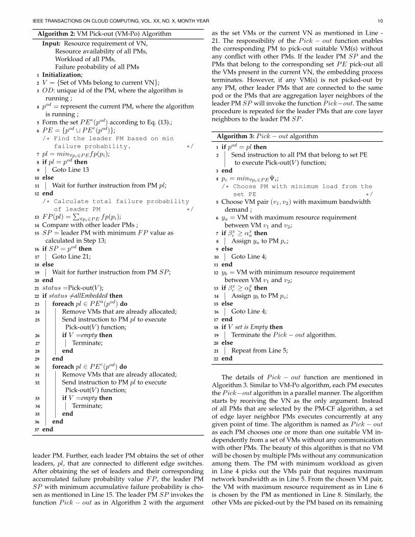
4.2 VM Pick-out (VM-Po) stageVM pick-out algorithm works in a distributed fashion. Thecentral server forwards separate copies of the details of theresultant PM cluster and the VN to each PM. Each PM
executes the VM-Po algorithm with own copy of inputs.The details of resultant PM cluster include the load of eachPM, the number of networking devices present betweeneach pair of PMs, available amount of computing resources(memory and CPU) on each PM, failure probability of eachPM etc. In order to reduce the network failure impact ontocurrent VN, multiple VMs can be placed onto a single PM.As the physical network link at the upper layer of the Fat-Tree topology carries out most of the data transmission,failure of such physical links brings maximum impact ontothe entire network. Considering this fact, our objectives areto minimize the required number of switches, physical linksand PMs for embedding the VN. When the PMs are allowedto host multiple VMs of single VN, it is obvious that the totalnumber of required PMs will be reduced. We have providedthe proof to minimize the required number of physical linksand physical switches in Lemma 1-3.
It is assumed that the failure probabilities of the PMs aredifferent. As mentioned in the second part of the objectivefunction in Eq. 16, minimizing the required number ofswitches infers the minimization of the required number ofphysical links, which is proved in Lemma 1. As discussedearlier, the basic difference between three types of neighborPMs is the number of switches involved in the communi-cation path. The number of switches involved in the pathbetween edge layer neighbors is 1 as in Eq. (13), whereasthe number of switches involved in the path between aggre-gation layer neighbors is 3 and core layer neighbors is 5 asin Eq. (14) and Eq. (15), respectively.
The Algorithm 2 starts by obtaining the unique ma-chine ID, OD, of the PM where the algorithm is running,as in Line 3. As the algorithm in each PM is executedindependently, the value of OD in each PM is different.pod represents the PM, where the algorithm is running asgiven in Line 4. Each PM forms a set PEe of edge layerneighbor PMs as in Line 5. In each PM, the elements of theset PEe are different. Since, the set of edge layer neighborPMs does not include the PM itself, another set PE isformed with help of union operation of the set PEe andthe PM itself as in Line 6. The reason behind forming theset of PE is to allow the VMs to be embedded onto thenearby PMs. Further, one leader PM is chosen based onthe failure probability of all the PMs that belong to the setPE. In other word, the failure of all PMs that are connectedto the same edge switch are compared to find the leaderPM. In Line 7, the PM with minimum failure probabilityvalue fp is chosen for the leader. As all the PMs have theinformation regarding the failure probability of each PMs,no additional communication is needed to choose the leader.Further, it is obvious that the resultant leader in each PMis same. The leader PM calculates the accumulative failureprobability FP by summing the individual neighbor PM’sfailure probability fp as mentioned in Line 13. This allowsus to consider the failure probability of other PMs withthe failure probability of leader PM during the embeddingprocess. On the other hand, the PMs that do not satisfy tobe the leader have to wait for further instruction from theircorresponding leader as in Line 11.
It is possible that there may be multiple leader PMs. Suchsituation may occur, if the PM cluster contains multipleedge switches. For each edge switch, there will be single
IEEE TRANSACTIONS ON CLOUD COMPUTING, VOL. XX, NO. X, MONTH YEAR 10
Algorithm 2: VM Pick-out (VM-Po) AlgorithmInput: Resource requirement of VN,
Resource availability of all PMs,Workload of all PMs,Failure probability of all PMs
1 Initialization;2 V = {Set of VMs belong to current VN};3 OD: unique id of the PM, where the algorithm is
running ;4 pod = represent the current PM, where the algorithm
is running ;5 Form the set PEe(pod) according to Eq. (13).;6 PE = {pod ∪ PEe(pod)};/* Find the leader PM based on min
failure probability. */7 pl = min∀pi∈PEfp(pi);8 if pl = pod then9 Goto Line 13
10 else11 Wait for further instruction from PM pl;12 end/* Calculate total failure probability
of leader PM */13 FP (pl) =
∑∀pi∈PE fp(pi);
14 Compare with other leader PMs ;15 SP = leader PM with minimum FP value as
calculated in Step 13;16 if SP = pod then17 Goto Line 21;18 else19 Wait for further instruction from PM SP ;20 end21 status =Pick-out(V );22 if status 6=allEmbedded then23 foreach pl ∈ PEa(pod) do24 Remove VMs that are already allocated;25 Send instruction to PM pl to execute
Pick-out(V ) function;26 if V =empty then27 Terminate;28 end29 end30 foreach pl ∈ PEc(pod) do31 Remove VMs that are already allocated;32 Send instruction to PM pl to execute
Pick-out(V ) function;33 if V =empty then34 Terminate;35 end36 end37 end
leader PM. Further, each leader PM obtains the set of otherleaders, pl, that are connected to different edge switches.After obtaining the set of leaders and their correspondingaccumulated failure probability value FP , the leader PMSP with minimum accumulative failure probability is cho-sen as mentioned in Line 15. The leader PM SP invokes thefunction Pick − out as in Algorithm 2 with the argument
as the set VMs or the current VN as mentioned in Line -21. The responsibility of the Pick − out function enablesthe corresponding PM to pick-out suitable VM(s) withoutany conflict with other PMs. If the leader PM SP and thePMs that belong to the corresponding set PE pick-out allthe VMs present in the current VN, the embedding processterminates. However, if any VM(s) is not picked-out byany PM, other leader PMs that are connected to the samepod or the PMs that are aggregation layer neighbors of theleader PM SP will invoke the function Pick−out. The sameprocedure is repeated for the leader PMs that are core layerneighbors to the leader PM SP .
Algorithm 3: Pick − out algorithm
1 if pod = pl then2 Send instruction to all PM that belong to set PE
to execute Pick-out(V ) function;3 end4 pc = min∀pi∈PEΨi;/* Choose PM with minimum load from the
set PE */5 Choose VM pair (v1, v2) with maximum bandwidth
demand ;6 ya = VM with maximum resource requirement
between VM v1 and v2;7 if βxc ≥ αxa then8 Assign ya to PM pc;9 else
10 Goto Line 4;11 end12 yb = VM with minimum resource requirement
between VM v1 and v2;13 if βxc ≥ αxb then14 Assign yb to PM pc;15 else16 Goto Line 4;17 end18 if V set is Empty then19 Terminate the Pick − out algorithm.20 else21 Repeat from Line 5;22 end
The details of Pick − out function are mentioned inAlgorithm 3. Similar to VM-Po algorithm, each PM executesthe Pick−out algorithm in a parallel manner. The algorithmstarts by receiving the VN as the only argument. Insteadof all PMs that are selected by the PM-CF algorithm, a setof edge layer neighbor PMs executes concurrently at anygiven point of time. The algorithm is named as Pick − outas each PM chooses one or more than one suitable VM in-dependently from a set of VMs without any communicationwith other PMs. The beauty of this algorithm is that no VMwill be chosen by multiple PMs without any communicationamong them. The PM with minimum workload as givenin Line 4 picks out the VMs pair that requires maximumnetwork bandwidth as in Line 5. From the chosen VM pair,the VM with maximum resource requirement as in Line 6is chosen by the PM as mentioned in Line 8. Similarly, theother VMs are picked-out by the PM based on its remaining
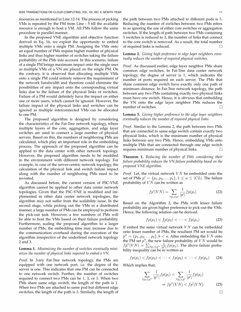
IEEE TRANSACTIONS ON CLOUD COMPUTING, VOL. XX, NO. X, MONTH YEAR 11
resources as mentioned in Line 12-14. The process of pickingVMs is repeated by the PM from Line - 5 till the availableresource is enough to host a VM. All PMs follow the sameprocedure in parallel manner.
In the proposed VNE algorithm and objective functionderived in Eq. 16, we exploit the opportunity to embedmultiple VMs onto a single PM. Assigning the VMs ontoan equal number of PMs require higher number of physicallinks and thus higher number of switches taking the failureprobability of the PMs into account. In this scenario, failureof a single PM brings maximum impact onto the single useras multiple VMs of a VN are placed on the single PM. Onthe contrary, it is observed that allocating multiple VMsonto a single PM could entirely remove the requirement ofthe network bandwidth and therefore could eliminate thepossibilities of any impact onto the corresponding virtuallinks due to the failure of the physical links or switches.Failure of a PM would definitely have the impact on eitherone or more users, which cannot be ignored. However, thefailure impact of the physical links and switches can beignored as multiple interconnected VMs can be allocatedto one PM.
The proposed algorithm is designed by consideringthe characteristics of the Fat-Tree network topology, wheremultiple layers of the core, aggregation, and edge layerswitches are used to connect a large number of physicalservers. Based on this, the numbers of neighboring PMs arecalculated, which play an important role in the embeddingprocess. The approach of the proposed algorithm can beapplied to the data center with other network topology.However, the proposed algorithm needs to be modifiedin the environment with different network topology. Forexample, in case of the server-centric network topology, thecalculation of the physical link and switch failure impactalong with the number of neighboring PMs need to berevisited.
As discussed before, the current version of FSC-VNEalgorithm cannot be applied to other data center networktopologies. Given that the FSC-VNE is modified and im-plemented in other data center network topologies, thealgorithm may not suffer from the scalability issue. In thesecond stage, while picking out the VMs in a distributedmanner, a large number of PMs can be employed to performthe pick-out task. However, a few numbers of PMs willbe able to host the VMs based on their failure probability.Furthermore, scaling the proposed algorithm to a largernumber of PMs, the embedding time may increase due tothe communication overhead during the execution of thealgorithm irrespective of the underlined network topology2 and 3.
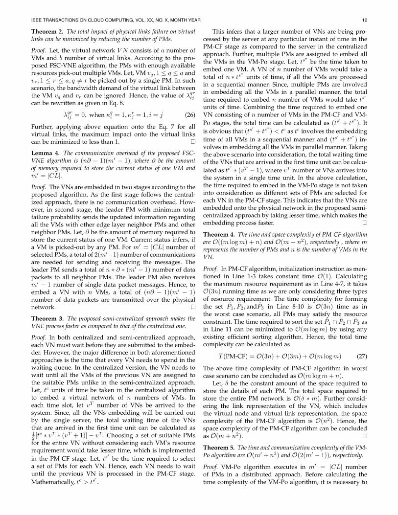
Lemma 1. Minimizing the number of switches eventually mini-mizes the number of physical links required to embed a VN.
Proof. In 3-ary Fat-Tree network topology, the PMs areequipped with one network port, i.e. the degree of theserver is one. This indicates that one PM can be connectedto one network switch. Further, the number of switchesrequired to connect two PMs can be 1, 3, or 5. When twoPMs share same edge switch, the length of the path is 1.When two PMs are attached to same pod but different edgeswitches, the length of the path is 3. Similarly, the length of
the path between two PMs attached to different pods is 5.Reducing the number of switches between two PMs refersto as ignoring the use of either core switches or aggregationswitches. If the length of path between two PMs containing5 switches is reduced to 3, the number of links that connectto the core switch is removed. As a result, the total numberof required links is reduced.
Lemma 2. Giving high preference to edge layer neighbors even-tually reduces the number of required physical switches.
Proof. As discussed earlier, edge layer neighbor PMs sharecommon edge switches. In Fat-Tree data center networktopology, the degree of server is 1, which indicates thenumber of ports required on each server. The PMs thatshare common edge switch have exactly only one path ofminimum distance. In Fat-Tree network topology, the pathbetween any two PMs containing exactly two physical linksmust have one switch. Hence, it is obvious that embeddingthe VN onto the edge layer neighbor PMs reduces thenumber of switches.
Lemma 3. Giving higher preference to the edge layer neighborseventually reduces the number of required physical links.
Proof. Similar to the Lemma 2, the path between two PMsthat are connected to same edge switch contain exactly twophysical links, which is the minimum number of physicallinks between any two PMs. Hence, embedding VMs ontomultiple PMs that are connected through one edge switchrequires minimum number of physical links.
Theorem 1. Reducing the number of PMs considering theirfailure probability reduces the VN failure probability based on theproposed VNE algorithm.
Proof. Let, the virtual network V N be embedded onto theset of PMs p′ = {p1, p2, . . . pa}, 1 ≤ a ≤ |CL|. The failureprobability of V N can be written as
fp′(V N) =∑∀pi∈p′
1
|p′|fp(pi) (22)
Based on the Algorithm 2, the PMs with lesser failureprobability are given higher preference to pick-out the VMs.Hence, the following relation can be derived.
fp(p1) < fp(p2) < · · · < fp(pa) (23)
If embed the same virtual network V N can be embeddedonto lesser number of PMs, the resultant PM set would bep′′ = {p1, p2, . . . pb}, b < a. After embedding the V N ontothe PM set p′′, the new failure probability of V N would befp′′(V N) =
∑∀pj∈p′′
1|p”|fp(pj). The above failure proba-
bility inequality can be re written as
fp(p1) < fp(p2) < · · · < fp(pb) < · · · < fp(pa) (24)
Which implies that,∑∀pi∈p′′
1
|p”|fp(pi) <
∑∀pj∈p′
1
|p′|fp(pj)
⇒ fp′′(V N) < fp′(V N) (25)
IEEE TRANSACTIONS ON CLOUD COMPUTING, VOL. XX, NO. X, MONTH YEAR 12
Theorem 2. The total impact of physical links failure on virtuallinks can be minimized by reducing the number of PMs.
Proof. Let, the virtual network V N consists of a number ofVMs and b number of virtual links. According to the pro-posed FSC-VNE algorithm, the PMs with enough availableresources pick-out multiple VMs. Let, VM vq, 1 ≤ q ≤ a andvr, 1 ≤ r ≤ a, q 6= r be picked-out by a single PM. In suchscenario, the bandwidth demand of the virtual link betweenthe VM vq and vr can be ignored. Hence, the value of λqrijcan be rewritten as given in Eq. 8.
λqrij = 0, when κqi = 1, κrj = 1, i = j (26)
Further, applying above equation onto the Eq. 7 for allvirtual links, the maximum impact onto the virtual linkscan be minimized to less than 1.
Lemma 4. The communication overhead of the proposed FSC-VNE algorithm is (n∂ − 1)(m′ − 1), where ∂ be the amountof memory required to store the current status of one VM andm′ = |CL|.
Proof. The VNs are embedded in two stages according to theproposed algorithm. As the first stage follows the central-ized approach, there is no communication overhead. How-ever, in second stage, the leader PM with minimum totalfailure probability sends the updated information regardingall the VMs with other edge layer neighbor PMs and otherneighbor PMs. Let, ∂ be the amount of memory required tostore the current status of one VM. Current status infers, ifa VM is picked-out by any PM. For m′ = |CL| number ofselected PMs, a total of 2(m′−1) number of communicationsare needed for sending and receiving the messages. Theleader PM sends a total of n ∗ ∂ ∗ (m′ − 1) number of datapackets to all neighbor PMs. The leader PM also receivesm′ − 1 number of single data packet messages. Hence, toembed a VN with n VMs, a total of (n∂ − 1)(m′ − 1)number of data packets are transmitted over the physicalnetwork.
Theorem 3. The proposed semi-centralized approach makes theVNE process faster as compared to that of the centralized one.
Proof. In both centralized and semi-centralized approach,each VN must wait before they are submitted to the embed-der. However, the major difference in both aforementionedapproaches is the time that every VN needs to spend in thewaiting queue. In the centralized version, the VN needs towait until all the VMs of the previous VN are assigned tothe suitable PMs unlike in the semi-centralized approach.Let, tc units of time be taken in the centralized algorithmto embed a virtual network of n numbers of VMs. Ineach time slot, let vT number of VNs be arrived to thesystem. Since, all the VNs embedding will be carried outby the single server, the total waiting time of the VNsthat are arrived in the first time unit can be calculated as12 [tc ∗ vT ∗ (vT + 1)]− vT . Choosing a set of suitable PMsfor the entire VN without considering each VM’s resourcerequirement would take lesser time, which is implementedin the PM-CF stage. Let, ts
′be the time required to select
a set of PMs for each VN. Hence, each VN needs to waituntil the previous VN is processed in the PM-CF stage.Mathematically, tc > ts
′.
This infers that a larger number of VNs are being pro-cessed by the server at any particular instant of time in thePM-CF stage as compared to the server in the centralizedapproach. Further, multiple PMs are assigned to embed allthe VMs in the VM-Po stage. Let, ts” be the time taken toembed one VM. A VN of n number of VMs would take atotal of n ∗ ts” units of time, if all the VMs are processedin a sequential manner. Since, multiple PMs are involvedin embedding all the VMs in a parallel manner, the totaltime required to embed n number of VMs would take ts”
units of time. Combining the time required to embed oneVN consisting of n number of VMs in the PM-CF and VM-Po stages, the total time can be calculated as (ts
′+ ts”). It
is obvious that (ts′+ ts”) < tc as tc involves the embedding
time of all VMs in a sequential manner and (ts′+ ts”) in-
volves in embedding all the VMs in parallel manner. Takingthe above scenario into consideration, the total waiting timeof the VNs that are arrived in the first time unit can be calcu-lated as tc
′ ∗ (vT − 1), where vT number of VNs arrives intothe system in a single time unit. In the above calculation,the time required to embed in the VM-Po stage is not takeninto consideration as different sets of PMs are selected foreach VN in the PM-CF stage. This indicates that the VNs areembedded onto the physical network in the proposed semi-centralized approach by taking lesser time, which makes theembedding process faster.
Theorem 4. The time and space complexity of PM-CF algorithmare O((m logm) + n) and O(m + n2), respectively , where mrepresents the number of PMs and n is the number of VMs in theVN.
Proof. In PM-CF algorithm, initialization instruction as men-tioned in Line 1-3 takes constant time O(1). Calculatingthe maximum resource requirement as in Line 4-7, it takesO(3n) running time as we are only considering three typesof resource requirement. The time complexity for formingthe set P1, P2, andP3 in Line 8-10 is O(3n) time as inthe worst case scenario, all PMs may satisfy the resourceconstraint. The time required to sort the set P1 ∩ P2 ∩ P3 asin Line 11 can be minimized to O(m logm) by using anyexisting efficient sorting algorithm. Hence, the total timecomplexity can be calculated as
T (PM-CF) = O(3n) +O(3m) +O(m logm) (27)
The above time complexity of PM-CF algorithm in worstcase scenario can be concluded as O(m logm+ n).
Let, δ be the constant amount of the space required tostore the details of each PM. The total space required tostore the entire PM network is O(δ ∗ m). Further consid-ering the link representation of the VN, which includesthe virtual node and virtual link representation, the spacecomplexity of the PM-CF algorithm is O(n2). Hence, thespace complexity of the PM-CF algorithm can be concludedas O(m+ n2).
Theorem 5. The time and communication complexity of the VM-Po algorithm are O(m′ + n3) and O(2(m′ − 1)), respectively.
Proof. VM-Po algorithm executes in m′ = |CL| numberof PMs in a distributed approach. Before calculating thetime complexity of the VM-Po algorithm, it is necessary to
IEEE TRANSACTIONS ON CLOUD COMPUTING, VOL. XX, NO. X, MONTH YEAR 13
analyze the running time complexity of Algorithm 3 as it isinvoked from the VM-Po algorithm for multiple times.
In Algorithm 3, finding PM with minimum load as inLine 4 has the time complexity of O(m′). Assuming that thelink representation is used to keep the information of VN, inthe worst case, O(n2) numbers of comparisons are requiredto find the VM pair with maximum bandwidth, which isrepeated for O(n2 ) number of times. Here, picking out theVM from the selected virtual edge takes a constant time.Hence, the total running time of the Pick-out algorithm canbe concluded to O(n2 ∗ n2 ) ≈ O(n3).
In Algorithm 2, forming the set of edge layer PMs inLine 6 requires the running time of O(m′). The runningtime for calculating the total failure probability as in Line13 is constant. Following this as in Line 15, finding theleader with minimum FP value takes O(m′) running time.The two for loops require O(m′) computational time. Asthe running time of Pick-out algorithm is O(n3), the totaltime complexity of the VM-Po algorithm can be concludedto O(m′ + n3).
The communication complexity of the VM-Po algorithmcan be seen as O(2(m′ − 1)) as discussed in Lemma 4. Theleader PM that is calculated in Line 13 invokes the Pick-out algorithm and sends the instruction to other m′ − 1number of PMs in order to execute the Pick-out algorithm.Upon execution of the Pick-out algorithm, m′ − 1 numberof messages are received by the leader PM. As a result, thetotal number of communications established in second stageis 2(m′ − 1).
5 PERFORMANCE EVALUATION
In this section, we evaluate the performance of proposedFSC-VNE algorithm by using a discrete event Java-basedsimulator. We compare our algorithm against two popularcentralized VNE algorithms VNE-DCC [17] and VIE-SR [31]considering the performance metrics such as acceptanceratio and average number of required resources.
5.1 Simulation Setup
In the simulation environment, one data center is formedwith a number of PMs that are connected by the Fat-Treenetwork topology. The simulation is performed on the smallscale data center, where each switch in the data centeris equipped with k = 32 number of ports. As discussedin Section 3, the maximum number of PMs that can beconnected with 32 ports switches is m = 323
4 = 8192 andthe total number of switches required is 1280 includingthe core, aggregation, and edge switches. In the simulation,it is assumed that the failure events are independent andrandom. These events also do not occur frequently. Basedon such properties, the number of failure events is modeledas a Poisson process with average number of failures (λ)0.01. The value of lambda is chosen to be very less toreflect the practical scenarios, where the number of failuresoccurring in the actual data center is relatively low. In thesimulation, assignment of the physical resources such asCPU, memory, and storage follows the Random distribu-tion. The maximum amount of storage and memory of aPM ranges between 1000GB−2000GB and 20GB−50GB,
respectively. The number of processing units in each PM israndomly distributed between 8 through 32. The maximumbandwidth capacity on each physical link is 100 Gbps.
The number of VMs in each VN ranges between 2through 10. The arrival rate of the incoming virtual networkfollows the Poisson distribution with the mean arrival rateof 10 VNs per 100 units of time. The mean arrival raterefers to as the average number of VNs arriving in every100 time units. Similarly, the lifetime of the VNs followsthe exponential distribution with mean lifetime of 250 timeunits. The lifetime of a VN refers to as the number of timeunits after which the VN is terminated. No specific topol-ogy is followed to construct a VN. However, a probabilityvalue is assigned to each virtual link, called virtual linkprobability. A VN with virtual link probability of 1 resultsin fully connected VN. The link probability of VNs in thesimulation environment ranges between 0.5 − 0.8. Similarto the physical network, virtual resources are distributedamong the VMs by following the random distribution. Theresource configurations of the VNs are not strictly heteroge-neous, which infers that some VNs can be homogeneous interms of their resource configurations. The CPU requirementfor each VM ranges from 1 through 4 numbers of CPUs.The required amount of memory and storage ranges from500MB through 4GB and 8GB through 20GB, respec-tively. Similarly, the bandwidth requirement for each VNranges from 50Mbps through 1Gbps.
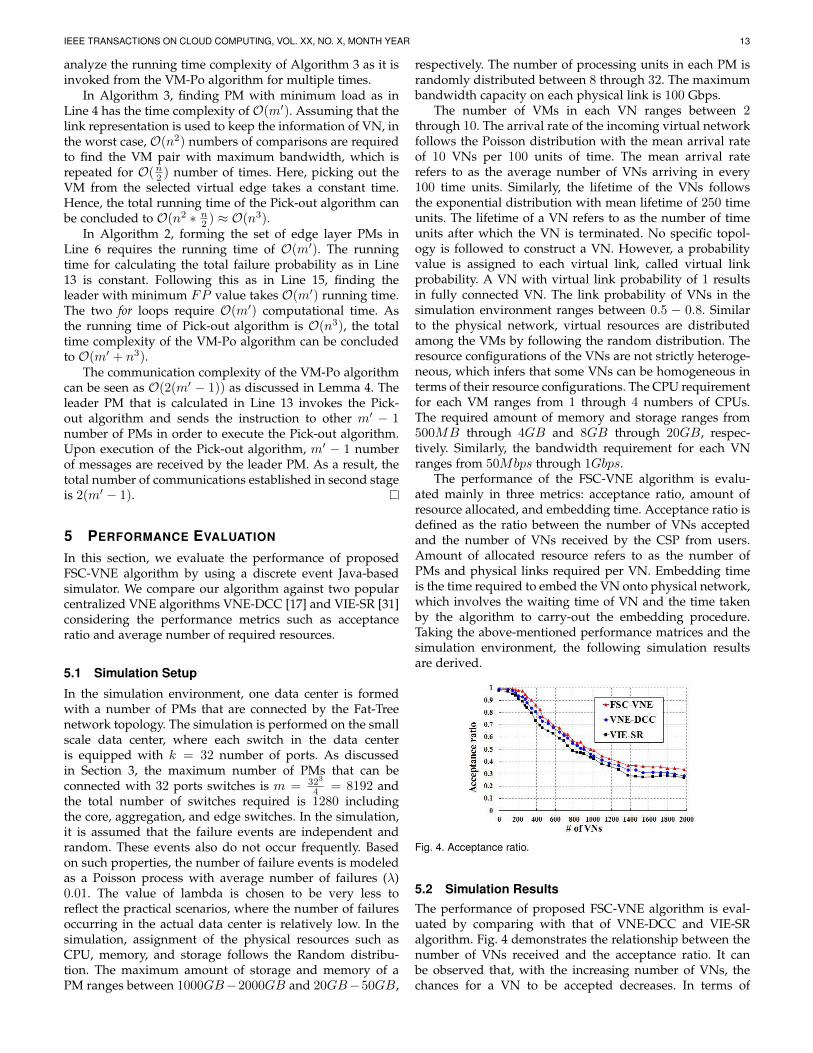
The performance of the FSC-VNE algorithm is evalu-ated mainly in three metrics: acceptance ratio, amount ofresource allocated, and embedding time. Acceptance ratio isdefined as the ratio between the number of VNs acceptedand the number of VNs received by the CSP from users.Amount of allocated resource refers to as the number ofPMs and physical links required per VN. Embedding timeis the time required to embed the VN onto physical network,which involves the waiting time of VN and the time takenby the algorithm to carry-out the embedding procedure.Taking the above-mentioned performance matrices and thesimulation environment, the following simulation resultsare derived.
Fig. 4. Acceptance ratio.
5.2 Simulation ResultsThe performance of proposed FSC-VNE algorithm is eval-uated by comparing with that of VNE-DCC and VIE-SRalgorithm. Fig. 4 demonstrates the relationship between thenumber of VNs received and the acceptance ratio. It canbe observed that, with the increasing number of VNs, thechances for a VN to be accepted decreases. In terms of
IEEE TRANSACTIONS ON CLOUD COMPUTING, VOL. XX, NO. X, MONTH YEAR 14
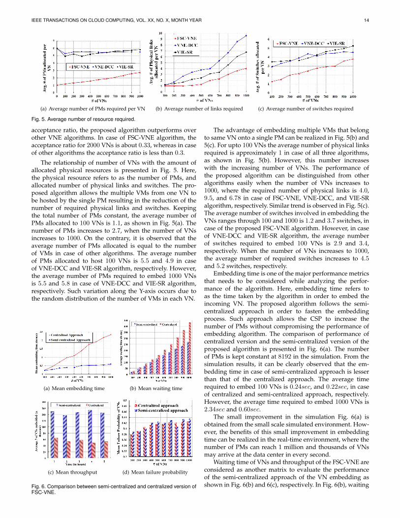
(a) Average number of PMs required per VN (b) Average number of links required (c) Average number of switches required
Fig. 5. Average number of resource required.
acceptance ratio, the proposed algorithm outperforms overother VNE algorithms. In case of FSC-VNE algorithm, theacceptance ratio for 2000 VNs is about 0.33, whereas in caseof other algorithms the acceptance ratio is less than 0.3.
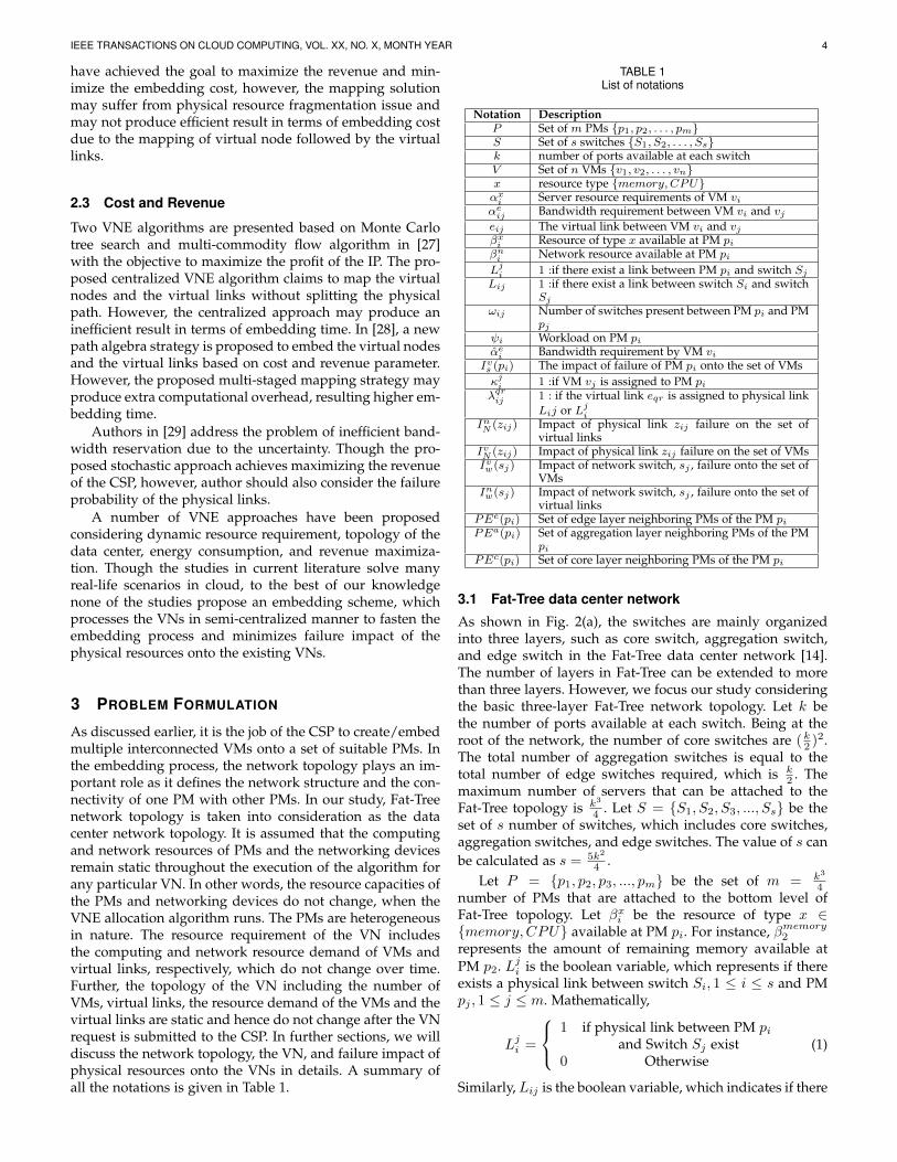
The relationship of number of VNs with the amount ofallocated physical resources is presented in Fig. 5. Here,the physical resource refers to as the number of PMs, andallocated number of physical links and switches. The pro-posed algorithm allows the multiple VMs from one VN tobe hosted by the single PM resulting in the reduction of thenumber of required physical links and switches. Keepingthe total number of PMs constant, the average number ofPMs allocated to 100 VNs is 1.1, as shown in Fig. 5(a). Thenumber of PMs increases to 2.7, when the number of VNsincreases to 1000. On the contrary, it is observed that theaverage number of PMs allocated is equal to the numberof VMs in case of other algorithms. The average numberof PMs allocated to host 100 VNs is 5.5 and 4.9 in caseof VNE-DCC and VIE-SR algorithm, respectively. However,the average number of PMs required to embed 1000 VNsis 5.5 and 5.8 in case of VNE-DCC and VIE-SR algorithm,respectively. Such variation along the Y-axis occurs due tothe random distribution of the number of VMs in each VN.
(a) Mean embedding time (b) Mean waiting time
(c) Mean throughput (d) Mean failure probability
Fig. 6. Comparison between semi-centralized and centralized version ofFSC-VNE.
The advantage of embedding multiple VMs that belongto same VN onto a single PM can be realized in Fig. 5(b) and5(c). For upto 100 VNs the average number of physical linksrequired is approximately 1 in case of all three algorithms,as shown in Fig. 5(b). However, this number increaseswith the increasing number of VNs. The performance ofthe proposed algorithm can be distinguished from otheralgorithms easily when the number of VNs increases to1000, where the required number of physical links is 4.0,9.5, and 6.78 in case of FSC-VNE, VNE-DCC, and VIE-SRalgorithm, respectively. Similar trend is observed in Fig. 5(c).The average number of switches involved in embedding theVNs ranges through 100 and 1000 is 1.2 and 3.7 switches, incase of the proposed FSC-VNE algorithm. However, in caseof VNE-DCC and VIE-SR algorithm, the average numberof switches required to embed 100 VNs is 2.9 and 3.4,respectively. When the number of VNs increases to 1000,the average number of required switches increases to 4.5and 5.2 switches, respectively.
Embedding time is one of the major performance metricsthat needs to be considered while analyzing the perfor-mance of the algorithm. Here, embedding time refers toas the time taken by the algorithm in order to embed theincoming VN. The proposed algorithm follows the semi-centralized approach in order to fasten the embeddingprocess. Such approach allows the CSP to increase thenumber of PMs without compromising the performance ofembedding algorithm. The comparison of performance ofcentralized version and the semi-centralized version of theproposed algorithm is presented in Fig. 6(a). The numberof PMs is kept constant at 8192 in the simulation. From thesimulation results, it can be clearly observed that the em-bedding time in case of semi-centralized approach is lesserthan that of the centralized approach. The average timerequired to embed 100 VNs is 0.24sec, and 0.22sec, in caseof centralized and semi-centralized approach, respectively.However, the average time required to embed 1000 VNs is2.34sec and 0.60sec.
The small improvement in the simulation Fig. 6(a) isobtained from the small scale simulated environment. How-ever, the benefits of this small improvement in embeddingtime can be realized in the real-time environment, where thenumber of PMs can reach 1 million and thousands of VNsmay arrive at the data center in every second.
Waiting time of VNs and throughput of the FSC-VNE areconsidered as another matrix to evaluate the performanceof the semi-centralized approach of the VN embedding asshown in Fig. 6(b) and 6(c), respectively. In Fig. 6(b), waiting
IEEE TRANSACTIONS ON CLOUD COMPUTING, VOL. XX, NO. X, MONTH YEAR 15
# of VNs
# of PMs
Em
bed
din
g t
ime(
in s
ec)
02000
0.2
1800 20001600
0.4
18001400 1600
0.6
1200 14001000 1200
0.8
1000800800
1
600 600400 400200 200
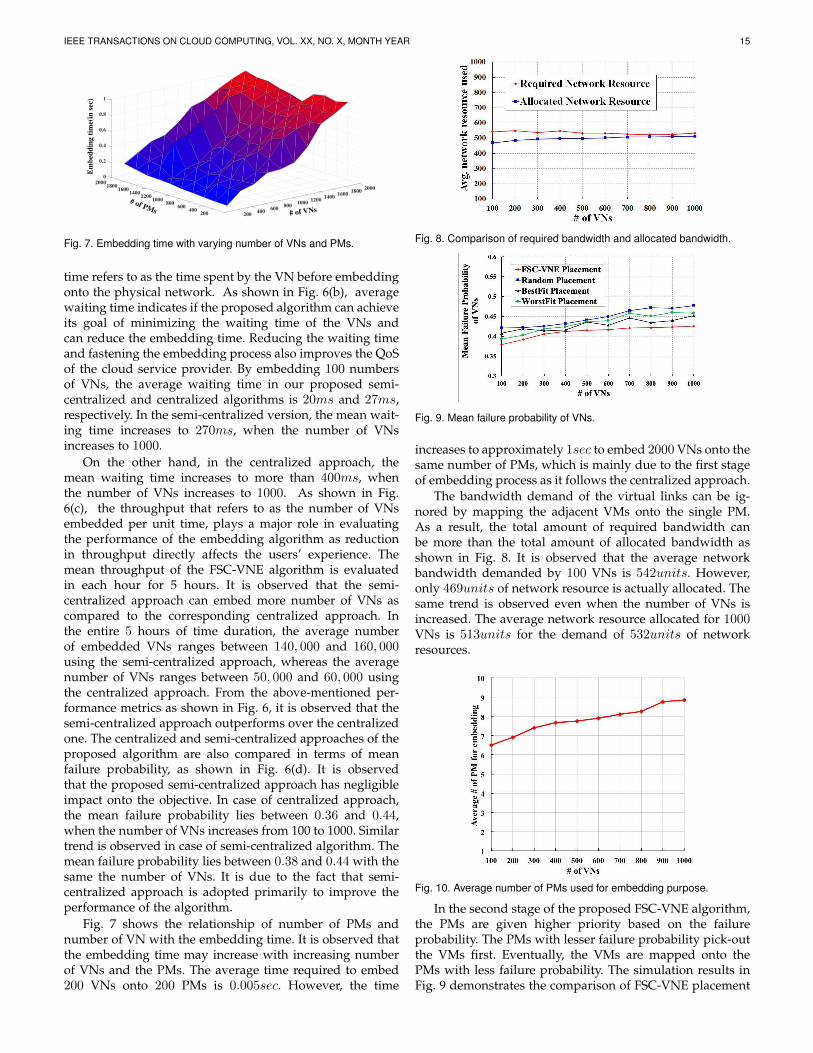
Fig. 7. Embedding time with varying number of VNs and PMs.
time refers to as the time spent by the VN before embeddingonto the physical network. As shown in Fig. 6(b), averagewaiting time indicates if the proposed algorithm can achieveits goal of minimizing the waiting time of the VNs andcan reduce the embedding time. Reducing the waiting timeand fastening the embedding process also improves the QoSof the cloud service provider. By embedding 100 numbersof VNs, the average waiting time in our proposed semi-centralized and centralized algorithms is 20ms and 27ms,respectively. In the semi-centralized version, the mean wait-ing time increases to 270ms, when the number of VNsincreases to 1000.
On the other hand, in the centralized approach, themean waiting time increases to more than 400ms, whenthe number of VNs increases to 1000. As shown in Fig.6(c), the throughput that refers to as the number of VNsembedded per unit time, plays a major role in evaluatingthe performance of the embedding algorithm as reductionin throughput directly affects the users’ experience. Themean throughput of the FSC-VNE algorithm is evaluatedin each hour for 5 hours. It is observed that the semi-centralized approach can embed more number of VNs ascompared to the corresponding centralized approach. Inthe entire 5 hours of time duration, the average numberof embedded VNs ranges between 140, 000 and 160, 000using the semi-centralized approach, whereas the averagenumber of VNs ranges between 50, 000 and 60, 000 usingthe centralized approach. From the above-mentioned per-formance metrics as shown in Fig. 6, it is observed that thesemi-centralized approach outperforms over the centralizedone. The centralized and semi-centralized approaches of theproposed algorithm are also compared in terms of meanfailure probability, as shown in Fig. 6(d). It is observedthat the proposed semi-centralized approach has negligibleimpact onto the objective. In case of centralized approach,the mean failure probability lies between 0.36 and 0.44,when the number of VNs increases from 100 to 1000. Similartrend is observed in case of semi-centralized algorithm. Themean failure probability lies between 0.38 and 0.44 with thesame the number of VNs. It is due to the fact that semi-centralized approach is adopted primarily to improve theperformance of the algorithm.
Fig. 7 shows the relationship of number of PMs andnumber of VN with the embedding time. It is observed thatthe embedding time may increase with increasing numberof VNs and the PMs. The average time required to embed200 VNs onto 200 PMs is 0.005sec. However, the time
Fig. 8. Comparison of required bandwidth and allocated bandwidth.
Fig. 9. Mean failure probability of VNs.
increases to approximately 1sec to embed 2000 VNs onto thesame number of PMs, which is mainly due to the first stageof embedding process as it follows the centralized approach.
The bandwidth demand of the virtual links can be ig-nored by mapping the adjacent VMs onto the single PM.As a result, the total amount of required bandwidth canbe more than the total amount of allocated bandwidth asshown in Fig. 8. It is observed that the average networkbandwidth demanded by 100 VNs is 542units. However,only 469units of network resource is actually allocated. Thesame trend is observed even when the number of VNs isincreased. The average network resource allocated for 1000VNs is 513units for the demand of 532units of networkresources.
Fig. 10. Average number of PMs used for embedding purpose.
In the second stage of the proposed FSC-VNE algorithm,the PMs are given higher priority based on the failureprobability. The PMs with lesser failure probability pick-outthe VMs first. Eventually, the VMs are mapped onto thePMs with less failure probability. The simulation results inFig. 9 demonstrates the comparison of FSC-VNE placement
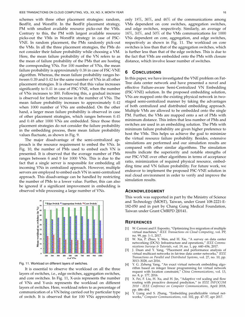
IEEE TRANSACTIONS ON CLOUD COMPUTING, VOL. XX, NO. X, MONTH YEAR 16
schemes with three other placement strategies: random,BestFit, and WorstFit. In the BestFit placement strategy,PM with smallest available resource picks-out the VMs.Contrary to this, the PM with largest available resourcepicks-out the VMs in WorstFit strategy in case of FSC-VNE. In random placement, the PMs randomly pick-outthe VMs. In all the three placement strategies, the PMs donot consider their failure probability while choosing a VM.Here, the mean failure probability of the VN refers to asthe mean of failure probability of the PMs that are hostingthe corresponding VNs. For 100 number of VNs, the meanfailure probability is approximately 0.38 in case of FSC-VNEalgorithm. Whereas, the mean failure probability ranges be-tween 0.39 and 0.42 for the same number of VNs in all otherplacement strategies. It is observed that this value increasessignificantly to 0.41 in case of FSC-VNE, when the numberof VNs increases to 300. Following this, a gradual increaseis observed for further increase in the number of VNs. Themean failure probability increases to approximately 0.42when 1000 number of VNs are embedded. On the otherhand, a larger mean failure probability is observed in caseof other placement strategies, which ranges between 0.45and 0.48 after 1000 VNs are embedded. Since those threeplacement strategies do not consider the failure probabilityin the embedding process, there mean failure probabilityvalues fluctuate, as shown in Fig. 9.
The major disadvantage of the semi-centralized ap-proach is the resource requirement to embed the VNs. InFig. 10, the number of PMs used to embed each VN ispresented. It is observed that the average number of PMsranges between 6 and 9 for 1000 VNs. This is due to thefact that a single server is responsible for embedding allincoming VNs in centralized approach. However, multipleservers are employed to embed each VN in semi-centralizedapproach. This disadvantage can be handled by restrictingthe number of PMs to a lower value. Further, this can alsobe ignored if a significant improvement in embedding isobserved while processing a large number of VNs.
Fig. 11. Workload on different layers of switches.
It is essential to observe the workload on all the threelayers of switches, i.e., edge switches, aggregation switches,and core switches. In Fig. 11, X-axis represents the numberof VNs and Y-axis represents the workload on differentlayers of switches. Here, workload refers to as percentage ofcommunication of a VN being carried out by particular typeof switch. It is observed that for 100 VNs approximately
only 18%, 36%, and 46% of the communications amongVMs dependent on core switches, aggregation switches,and edge switches, respectively. Similarly, an average of16%, 34%, and 50% of the VMs communications for 1000VNs dependent on core, aggregation, and edge switches,respectively as shown in Fig. 11. The workload on coreswitches is less than that of the aggregation switches, whichis further less than that of the edge switches. This is due tothe fact that VMs are embedded onto the PMs with closuredistance, which involve lesser number of switches.
6 CONCLUSIONS
In this paper, we have investigated the VNE problem on Fat-Tree data center network and have presented a novel andeffective Failure-aware Semi-Centralized VN Embedding(FSC-VNE) solution. In the proposed embedding solution,VNs are mapped onto the existing physical network in two-staged semi-centralized manner by taking the advantagesof both centralized and distributed embedding approach.Multiple VMs are allowed to be embedded onto the singlePM. Further, the VMs are mapped onto a set of PMs withminimum distance. This infers that less number of PMs andswitches are used in an embedding solution. The PMs withminimum failure probability are given higher preference tohost the VMs. This helps us achieve the goal to minimizethe virtual resource failure probability. Besides, extensivesimulations are performed and our simulation results arecompared with other similar algorithms. The simulationresults indicate the superiority and notable strengths ofour FSC-VNE over other algorithms in terms of acceptanceratio, minimization of required physical resource, embed-ding time and VN failure probability. For future work, weendeavor to implement the proposed FSC-VNE solution inreal cloud environment in order to verify and improve thesimulation results.
ACKNOWLEDGMENT
This work was supported in part by the Ministry of Scienceand Technology (MOST), Taiwan, under Grant 108-2221-E-182-050 and in part by Chang Gung Medical Foundation,Taiwan under Grant CMRPD 2J0141.
REFERENCES
[1] W. Cerroni and F. Esposito, “Optimizing live migration of multiplevirtual machines,” IEEE Transactions on Cloud Computing, vol. PP,no. 99, pp. 1–1, 2017.
[2] W. Xia, P. Zhao, Y. Wen, and H. Xie, “A survey on data centernetworking (DCN): Infrastructure and operations,” IEEE Commu-nications Surveys & Tutorials, vol. 19, no. 1, pp. 640–656, 2017.
[3] J. Duan and Y. Yang, “Placement and performance analysis ofvirtual multicast networks in fat-tree data center networks,” IEEETransactions on Parallel and Distributed Systems, vol. 27, no. 10, pp.3013–3028, oct 2016.
[4] Y. G. Zeheng Yang, “An exact virtual network embedding algo-rithm based on integer linear programming for virtual networkrequest with location constraint,” China Communications, vol. 13,no. 8, p. 177, 2016.
[5] X. Fei, F. Liu, H. Xu, and H. Jin, “Adaptive vnf scaling and flowrouting with proactive demand prediction,” in IEEE INFOCOM2018 - IEEE Conference on Computer Communications, April 2018,pp. 486–494.
[6] Y. Liang and S. Zhang, “Embedding parallelizable virtual net-works,” Computer Communications, vol. 102, pp. 47–57, apr 2017.
IEEE TRANSACTIONS ON CLOUD COMPUTING, VOL. XX, NO. X, MONTH YEAR 17
[7] X. Li, X. Jiang, P. Garraghan, and Z. Wu, “Holistic energy andfailure aware workload scheduling in cloud datacenters,” FutureGeneration Computer Systems, vol. 78, no. Part 3, pp. 887 – 900, 2018.
[8] M. N. Cheraghlou, A. Khadem-Zadeh, and M. Haghparast, “Asurvey of fault tolerance architecture in cloud computing,” Journalof Network and Computer Applications, vol. 61, pp. 81 – 92, 2016.
[9] P. T. Endo, G. L. Santos, D. Rosendo, D. M. Gomes, A. Moreira,J. Kelner, D. Sadok, G. E. Goncalves, and M. Mahloo, “Minimizingand managing cloud failures,” Computer, vol. 50, no. 11, pp. 86–90,2017.
[10] C. Cerin, C. Coti, P. Delort, F. Diaz, M. Gagnaire, Q. Gaumer, N.Guillaume, J. Lous, S. Lubiarz, J. Raffaelli, K. Shiozaki, H. Schauer,J. Smets, L. Seguin and A. Ville, “Downtime statistics of currentcloud solutions,” International Working Group on Cloud ComputingResiliency, Tech. Rep, 2013.
[11] H. S. Gunawi, M. Hao, R. O. Suminto, A. Laksono, A. D.Satria, J. Adityatama, and K. J. Eliazar, “Why does the cloudstop computing?: Lessons from hundreds of service outages,” inProceedings of the Seventh ACM Symposium on Cloud Computing, ser.SoCC ’16. New York, NY, USA: ACM, 2016, pp. 1–16. [Online].Available: http://doi.acm.org/10.1145/2987550.2987583
[12] M. T. Beck, A. Fischer, J. F. Botero, C. Linnhoff-Popien, andH. de Meer, “Distributed and scalable embedding of virtual net-works,” Journal of Network and Computer Applications, vol. 56, pp.124–136, oct 2015.
[13] P. K. Sahoo, C. K. Dehury, and B. Veeravalli, “Lvrm: On the designof efficient link based virtual resource management algorithmfor cloud platforms,” IEEE Transactions on Parallel and DistributedSystems, vol. 29, no. 4, pp. 887–900, April 2018.
[14] N. Ogino, T. Kitahara, S. Arakawa, and M. Murata, “Virtual net-work embedding with multiple priority classes sharing substrateresources,” Computer Networks, vol. 112, pp. 52–66, jan 2017.
[15] Z. Xu, F. Liu, Tao Wang, and H. Xu, “Demystifying the energyefficiency of network function virtualization,” in 2016 IEEE/ACM24th International Symposium on Quality of Service (IWQoS), June2016, pp. 1–10.
[16] L. Gong, H. Jiang, Y. Wang, and Z. Zhu, “Novel location-constrained virtual network embedding LC-VNE algorithms to-wards integrated node and link mapping,” IEEE/ACM Transactionson Networking, vol. 24, no. 6, pp. 3648–3661, dec 2016.
[17] P. Zhang, H. Yao, and Y. Liu, “Virtual network embedding basedon the degree and clustering coefficient information,” IEEE Access,vol. 4, pp. 8572–8580, 2016.
[18] A. Alsarhan, A. Itradat, A. Y. Al-Dubai, A. Y. Zomaya, and G. Min,“Adaptive resource allocation and provisioning in multi-servicecloud environments,” IEEE Transactions on Parallel and DistributedSystems, vol. 29, no. 1, pp. 31–42, Jan 2018.
[19] L. Yin, Z. Chen, L. Qiu, and Y. Wen, “Interference based virtualnetwork embedding,” in 2016 IEEE International Conference onCommunications (ICC). IEEE, may 2016.
[20] Q. Zhang, F. Liu, and C. Zeng, “Adaptive interference-aware vnfplacement for service-customized 5g network slices,” in IEEEINFOCOM 2019 - IEEE Conference on Computer Communications,April 2019, pp. 2449–2457.
[21] Y. Xiao, Q. Zhang, F. Liu, J. Wang, M. Zhao, Z. Zhang, andJ. Zhang, “Nfvdeep: adaptive online service function chain de-ployment with deep reinforcement learning,” in Proceedings of theInternational Symposium on Quality of Service. ACM, 2019, p. 21.
[22] A. Aral and T. Ovatman, “Network-aware embedding of virtualmachine clusters onto federated cloud infrastructure,” Journal ofSystems and Software, vol. 120, pp. 89–104, oct 2016.
[23] F. Yan, T. T. Lee, and W. Hu, “Congestion-aware embedding ofheterogeneous bandwidth virtual data centers with hose modelabstraction,” IEEE/ACM Transactions on Networking, vol. 25, no. 2,pp. 806–819, April 2017.
[24] H. Cao, L. Yang, and H. Zhu, “Novel node-ranking approachand multiple topology attributes-based embedding algorithmfor single-domain virtual network embedding,” IEEE Internet ofThings Journal, vol. 5, no. 1, pp. 108–120, Feb 2018.
[25] T. Mano, T. Inoue, K. Mizutani, and O. Akashi, “Reducing densevirtual networks for fast embedding,” in IEEE INFOCOM 2016 -The 35th Annual IEEE International Conference on Computer Commu-nications. IEEE, apr 2016.
[26] T. Wang and M. Hamdi, “Presto: Towards efficient online virtualnetwork embedding in virtualized cloud data centers,” ComputerNetworks, vol. 106, pp. 196 – 208, 2016.
[27] S. Haeri and L. Trajkovic, “Virtual network embedding via montecarlo tree search,” IEEE Transactions on Cybernetics, vol. 48, no. 2,pp. 510–521, Feb 2018.
[28] X. Hesselbach, J. R. Amazonas, S. Villanueva, and J. F. Botero,“Coordinated node and link mapping vne using a new pathsalgebra strategy,” Journal of Network and Computer Applications,vol. 69, no. Supplement C, pp. 14 – 26, 2016.
[29] L. Yu, H. Shen, Z. Cai, L. Liu, and C. Pu, “Towards bandwidthguarantee for virtual clusters under demand uncertainty in multi-tenant clouds,” IEEE Transactions on Parallel and Distributed Sys-tems, vol. 29, no. 2, pp. 450–465, Feb 2018.
[30] A. Zhou, S. Wang, B. Cheng, Z. Zheng, F. Yang, R. N. Chang,M. R. Lyu, and R. Buyya, “Cloud service reliability enhancementvia virtual machine placement optimization,” IEEE Transactions onServices Computing, vol. 10, no. 6, pp. 902–913, Nov 2017.
[31] R. Yu, G. Xue, and X. Zhang, “Towards min-cost virtual infrastruc-ture embedding,” in 2015 IEEE Global Communications Conference(GLOBECOM). Institute of Electrical and Electronics Engineers(IEEE), dec 2015.
Chinmaya Kumar Dehury Chinmaya KumarDehury received bachelor degree from Sam-balpur University, India, in June 2009 and MCAdegree from Biju Pattnaik University of Technol-ogy, India, in June 2013. He received the PhDDegree in the department of Computer Scienceand Information Engineering, Chang Gung Uni-versity, Taiwan. Currently, he is a postdoctoralresearch fellow in the Mobile & Cloud Lab, In-stitute of Computer Science, University of Tartu,Estonia. His research interests include schedul-
ing, resource management and fault tolerance problems of Cloud andfog Computing, and the application of artificial intelligence in cloud man-agement. He is also reviewer to several journals and conferences, suchas IEEE TPDS, IEEE JSAC, Wiley Software: Practice and Experience,etc.
Prasan Kumar Sahoo Prasan Kumar Sahooreceived the B.Sc. degree in physics (with Hon-ors), the M.Sc. degree in mathematics both fromUtkal University, Bhubaneswar, India, in 1987and 1994, respectively. He received the M.Tech.degree in computer science from the Indian In-stitute of Technology (IIT), Kharagpur, India, in2000, the first Ph.D. degree in mathematics fromUtkal University, in 2002, and the second Ph.D.degree in computer science and information en-gineering from the National Central University,
Taiwan, in 2009. He is currently a Professor in the Department of Com-puter Science and Information Engineering, Chang Gung University,Taiwan. He is an Adjunct Researcher in the Division of Colon and RectalSurgery, Chang Gung Memorial Hospital, Linkou, Taiwan since 2018. Hehas worked as an Associate Professor in the Department of InformationManagement, Vanung University, Taiwan, from 2007 to 2011. He was aVisiting Associate Professor in the Department of Computer Science,Universite Claude Bernard Lyon 1, Villeurbanne, France. His currentresearch interests include artificial intelligence, big data analytic, cloudcomputing, and IoT. He is the Lead Guest Editor, special issue ofElectronics journal and an Editorial Board Member for the InternationalJournal of Vehicle Information and Communication Systems. He hasworked as the Program Committee Member of several IEEE and ACMconferences and is a senior member, IEEE.