Embed Size (px)
Citation preview
IEEE TRANSACTIONS ON ANTENNAS AND PROPAGATION, VOL. 61, NO. 5, MAY 2013 2411
A Method for Determining Optimal EBG ReflectionPhase for Low Profile Dipole Antennas
Ian T. McMichael, Member, IEEE, Amir I. Zaghloul, Life Fellow, IEEE, and Mark S. Mirotznik, SeniorMember, IEEE
Abstract—An analytical method for determining the optimal re-flection phase of an electromagnetic band gap (EBG) ground planeto match a low profile dipole antenna is introduced. Image theoryis used to incorporate the near field coupling between a dipole an-tenna and the ground plane. The main contribution of this paper isto show that the optimal EBG reflection phase can be determinedat discrete frequencies where a theoretically perfect return loss oc-curs. The optimal reflection phase is then obtained over awider fre-quency band of interest and is related to the antenna’s return lossfor a given feed impedance and antenna height above the EBG. Theresulting reflection phase can be used as a reference for designingan EBG ground plane that is well matched to the antenna withouttime consuming iterative full wave numerical simulations. Numer-ical modeling results are compared to the optimal return loss de-rived from the analytical method to validate the design process. Itis also shown that, for certain antennas, vias are not always nec-essary in the construction of the EBG, which eases the manufac-turing process. Finally, a dipole and EBG are constructed usingthe optimal design method and measurements are compared to thesimulations.
Index Terms—Electromagnetic band gap (EBG), low profile an-tenna, reflection phase.
I. INTRODUCTION
E LECTROMAGNETIC band gap (EBG) structures havebeen widely investigated as ground planes for low pro-
file antennas because of their characteristic surface wave bandgaps and frequency dependent reflection phase [1], [2]. It hasbeen shown that a reflection phase of zero degrees will causea horizontal dipole placed close to an EBG to radiate more ef-ficiently than the same dipole placed close to a perfect electri-cally conducting (PEC) ground plane. However, even greaterimprovements to radiation efficiency occur when the reflectionphase is [3]. The reasoning for this improved effi-ciency was explained in [4] using the model of a dipole and itsimage, where the image dipole incorporates a near-field mutualimpedance. The image theory concept is extended in this paper
Manuscript received August 06, 2012; revised November 30, 2012; acceptedJanuary 22, 2013. Date of publication February 01, 2013; date of current versionMay 01, 2013.I. T.McMichael is with the University of Delaware, Newark, DE 19716USA,
and also with the U.S. Army CERDEC RDECOM NVESD, Ft. Belvoir, VA22060 USA.A. I. Zaghloul is with the Army Research Laboratory, Adelphi, MD 20783
USA.M. S.Mirotznik is with the Electrical and Computer Engineering Department,
University of Delaware, Newark, DE 19716 USA (e-mail: [email protected]).Color versions of one or more of the figures in this paper are available online
at http://ieeexplore.ieee.org.Digital Object Identifier 10.1109/TAP.2013.2244552
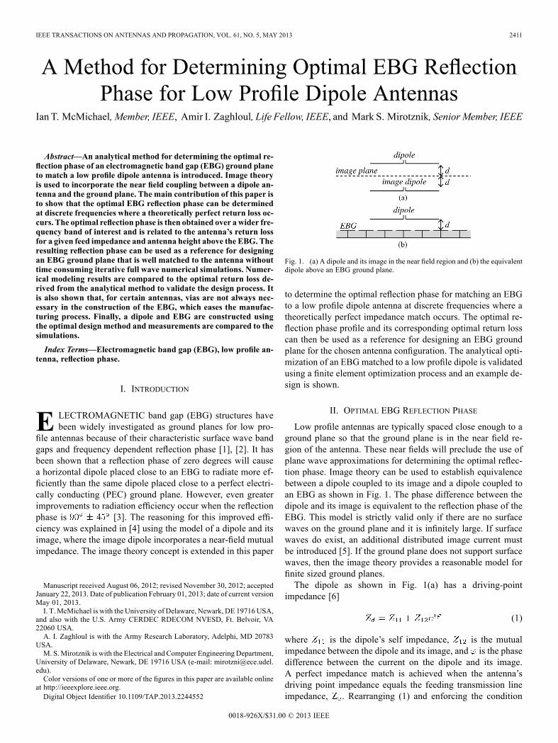
Fig. 1. (a) A dipole and its image in the near field region and (b) the equivalentdipole above an EBG ground plane.
to determine the optimal reflection phase for matching an EBGto a low profile dipole antenna at discrete frequencies where atheoretically perfect impedance match occurs. The optimal re-flection phase profile and its corresponding optimal return losscan then be used as a reference for designing an EBG groundplane for the chosen antenna configuration. The analytical opti-mization of an EBG matched to a low profile dipole is validatedusing a finite element optimization process and an example de-sign is shown.
II. OPTIMAL EBG REFLECTION PHASE
Low profile antennas are typically spaced close enough to aground plane so that the ground plane is in the near field re-gion of the antenna. These near fields will preclude the use ofplane wave approximations for determining the optimal reflec-tion phase. Image theory can be used to establish equivalencebetween a dipole coupled to its image and a dipole coupled toan EBG as shown in Fig. 1. The phase difference between thedipole and its image is equivalent to the reflection phase of theEBG. This model is strictly valid only if there are no surfacewaves on the ground plane and it is infinitely large. If surfacewaves do exist, an additional distributed image current mustbe introduced [5]. If the ground plane does not support surfacewaves, then the image theory provides a reasonable model forfinite sized ground planes.The dipole as shown in Fig. 1(a) has a driving-point
impedance [6]
(1)
where is the dipole’s self impedance, is the mutualimpedance between the dipole and its image, and is the phasedifference between the current on the dipole and its image.A perfect impedance match is achieved when the antenna’sdriving point impedance equals the feeding transmission lineimpedance, . Rearranging (1) and enforcing the condition
0018-926X/$31.00 © 2013 IEEE

2412 IEEE TRANSACTIONS ON ANTENNAS AND PROPAGATION, VOL. 61, NO. 5, MAY 2013
that the driving point impedance equals the feed line impedance,we can write
(2)
which is clearly only valid if the magnitude of the quantity onthe right hand side is unity. The magnitude of the right handside of (2) can be plotted over frequency to determine the exactfrequencies where it equals 1. These discrete impedance valuescan then be inserted into
(3)
to determine the phase values that produce a theoretically per-fect impedance match. Since the phase term in (1) is equivalentto the reflection phase of an EBG a distance away from theantenna, a designer can create an EBG ground plane to exhibitthis reflection phase using published analytical EBG impedanceformulas [5]. In this manner, a very good return loss can be re-alized for a given feed impedance and antenna height by using asingle numerical model to determine and of an antennaand its image. This is more computationally efficient than usingiterative numerical modeling optimization of an antenna and anEBG, which can be very time consuming.Alternatively, one can use (1) to find the best possible phase
term over a range of frequencies instead of finding a perfectimpedance match condition at discrete frequencies. By inserting(1) into the expression for return loss, we can write
(4)
A simple numerical script can be written to find the minimumreturn loss at each frequency of interest by calculating (4) overa phase range of . It should be noted that while (4)can be used to find an optimum value for the return loss over arange of frequencies, the optimized value is not necessarily verylow at all frequencies. The dipole is still limited in its radiationcapability away from resonance.
III. NUMERICAL VALIDATION
An ideal thin dipole with a lumped port was numericallymod-eled using the Ansoft HFSS finite element software package.The thin dipole was 91 mm long with a 1.575 GHz resonant fre-quency in free space. A replica dipole was then modeled a dis-tance away and the and values werecomputed over a range of frequencies. Fig. 2 shows the com-puted self impedance and mutual impedance of the two dipoles.The same dipole as described above was then modeled at a
distance (or ) above a square patch mush-room-type EBG with a substrate height of 5 mm, substrate of5.8, and patch gap width of 1 mm. The size of the EBG was 7unit cells by 7 unit cells, where a unit cell size is defined as thepatch width plus the patch gap width.The patch width was varied at several discrete frequencies
while all other parameters were held constant to find the values
Fig. 2. Self impedance and mutual impedance of a pair of 91-mm-long dipolesseparated a distance of 12.72 mm.
TABLE INUMERICALLY OPTIMIZED PATCH WIDTHS
Fig. 3. Magnitude of the impedance ratio on the right hand side of (2). Thequantity crosses 1 at two discrete frequencies, 1.5 and 1.74 GHz, where thedipole’s driving point impedance matches the feeding transmission line’simpedance.
that produced the best return loss at each frequency. The optimalEBG parameters were then used in a unit cell analysis to deter-mine the corresponding reflection phase. The patch widths thatwere numerically determined to produce the best return loss atdiscrete frequencies are shown in Table I.Using a feed line impedance of 50 , the analytical optimiza-
tion method described in Section II produced two discrete fre-quencies corresponding to a perfect impedance match. Fig. 3shows the magnitude of the impedance ratio on the right handside of (2) as a function of frequency, which has a value of 1at two distinct frequencies. Fig. 4(a) shows the analytically de-rived optimal reflection phase curve along with the numericallyoptimized reflection phase. Fig. 4(b) shows the analytically op-timized S11 for the dipole compared to the numerically opti-mized S11. It can be seen that the analytically derived phasevalues are in good agreement with the numerically optimizedvalues. The numerically derived S11 diverges from the optimal

MCMICHAEL et al.: METHOD FOR DETERMINING OPTIMAL EBG REFLECTION PHASE FOR LOW PROFILE DIPOLE ANTENNAS 2413
Fig. 4. (a) Analytically derived optimal reflection phase and HFSS optimalreflection phase for a dipole above an EBG. (b) Analytically derived optimalS11 and HFSS optimal S11 for a dipole above an EBG.
S11 at higher frequencies because these frequencies are outsideof the TE surface wave band gap region.In the above example, the optimal return loss for the dipole at
1.5 GHz occurs for an EBG reflection phase of approximately100 , which is in the expected range of according to[3]. However, since the optimal return loss is a function of ,which is affected by the dipole height, and a function of , itcan be shown that the optimal return loss is not necessarily in therange of for all dipole configurations. As an examplecase, the optimal S11 and reflection phase were computed forthe same dipole pair as in the previous example but with a feedimpedance of 150 instead of 50 . The resulting reflectionphase is shown in Fig. 5 and compared to the reflection phase fora 50 feed impedance. The S11 for the 150 feed impedanceis shown in Fig. 6 as compared to the S11 for the 50 feed. Theoptimal S11 for the 150 feed now occurs at 1.59 GHz wherethe reflection phase is approximately 0 . Another result of in-creasing the feed impedance in this example is that the band-width for a good return loss increased significantly. However,TE surface waves are supported above 1.59 GHz. Therefore,even though increasing the feed impedance increases the theo-retical bandwidth, surface waves over part of the band preventthe theoretically optimal return loss from being achieved overthe entire band.Increasing the physical spacing between the dipole and its
image, which represents the dipole being raised higher abovethe EBG, causes the two dips in the optimal return loss to come
Fig. 5. Analytically derived optimal reflection phase for two different feedimpedance values.
Fig. 6. Analytically derived optimal return loss for two different feedimpedance values.
together. Increasing the dipole spacing also causes the optimalreflection phase to increase. This trend is intuitively reasonablesince, in the case where the dipole spacing is increased to ahalf wavelength, or equivalently one quarter wavelength abovea ground plane, the dipole is expected to radiate well when thereflection phase is 180 like a PEC produces.
IV. EBG DESIGN EXAMPLE
In the previous section, it was shown that a theoretically per-fect return loss can be achieved for a horizontal dipole over anEBG. Since the dipole is well matched at a frequency where TEsurface waves are not supported, we now show that this impliesvias are not necessary in the construction of the EBG for partic-ular feed configurations.It is shown in [5] that a TE surface wave traveling in the plane
of the EBG and decaying away from the EBG surface will havethe form
(5)
where is the direction in which the wave is traveling, is thedirection away from the face of the EBG in which the wave isdecaying, is the propagation constant, is the decay constant,and is an amplitude. The propagation constant for the TEmode can be expressed as
(6)
2414 IEEE TRANSACTIONS ON ANTENNAS AND PROPAGATION, VOL. 61, NO. 5, MAY 2013
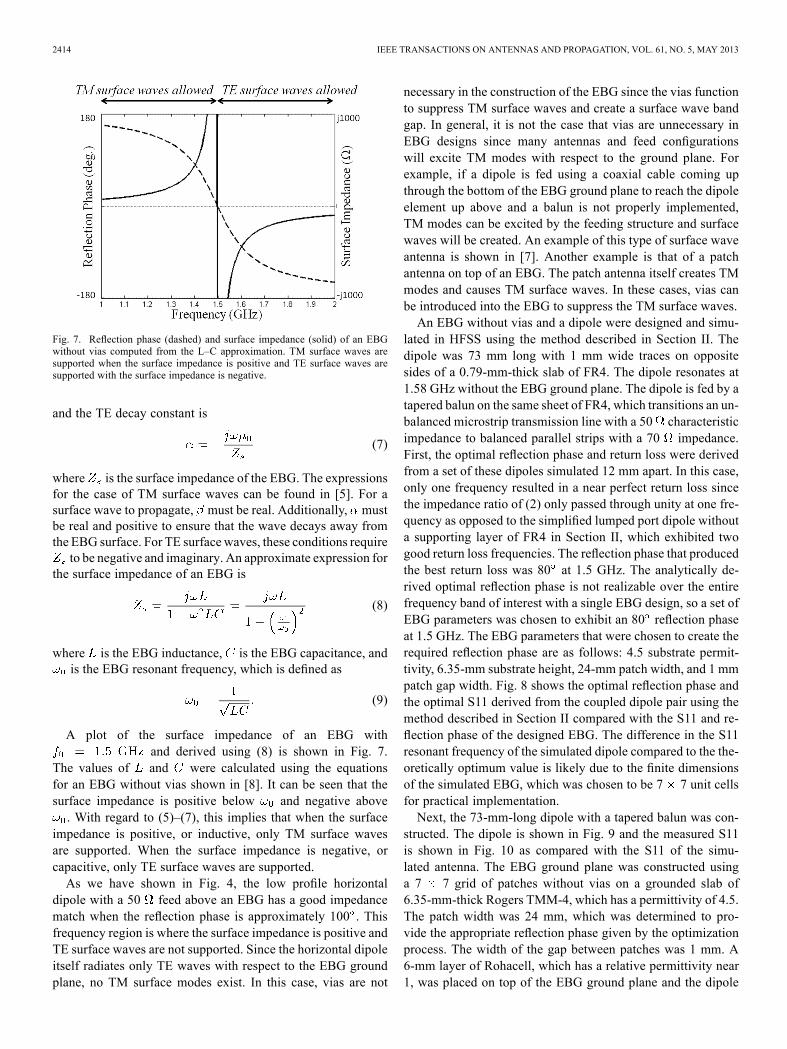
Fig. 7. Reflection phase (dashed) and surface impedance (solid) of an EBGwithout vias computed from the L–C approximation. TM surface waves aresupported when the surface impedance is positive and TE surface waves aresupported with the surface impedance is negative.
and the TE decay constant is
(7)
where is the surface impedance of the EBG. The expressionsfor the case of TM surface waves can be found in [5]. For asurface wave to propagate, must be real. Additionally, mustbe real and positive to ensure that the wave decays away fromthe EBG surface. For TE surface waves, these conditions requireto be negative and imaginary. An approximate expression for
the surface impedance of an EBG is
(8)
where is the EBG inductance, is the EBG capacitance, andis the EBG resonant frequency, which is defined as
(9)
A plot of the surface impedance of an EBG withand derived using (8) is shown in Fig. 7.
The values of and were calculated using the equationsfor an EBG without vias shown in [8]. It can be seen that thesurface impedance is positive below and negative above. With regard to (5)–(7), this implies that when the surface
impedance is positive, or inductive, only TM surface wavesare supported. When the surface impedance is negative, orcapacitive, only TE surface waves are supported.As we have shown in Fig. 4, the low profile horizontal
dipole with a 50 feed above an EBG has a good impedancematch when the reflection phase is approximately 100 . Thisfrequency region is where the surface impedance is positive andTE surface waves are not supported. Since the horizontal dipoleitself radiates only TE waves with respect to the EBG groundplane, no TM surface modes exist. In this case, vias are not
necessary in the construction of the EBG since the vias functionto suppress TM surface waves and create a surface wave bandgap. In general, it is not the case that vias are unnecessary inEBG designs since many antennas and feed configurationswill excite TM modes with respect to the ground plane. Forexample, if a dipole is fed using a coaxial cable coming upthrough the bottom of the EBG ground plane to reach the dipoleelement up above and a balun is not properly implemented,TM modes can be excited by the feeding structure and surfacewaves will be created. An example of this type of surface waveantenna is shown in [7]. Another example is that of a patchantenna on top of an EBG. The patch antenna itself creates TMmodes and causes TM surface waves. In these cases, vias canbe introduced into the EBG to suppress the TM surface waves.An EBG without vias and a dipole were designed and simu-
lated in HFSS using the method described in Section II. Thedipole was 73 mm long with 1 mm wide traces on oppositesides of a 0.79-mm-thick slab of FR4. The dipole resonates at1.58 GHz without the EBG ground plane. The dipole is fed by atapered balun on the same sheet of FR4, which transitions an un-balanced microstrip transmission line with a 50 characteristicimpedance to balanced parallel strips with a 70 impedance.First, the optimal reflection phase and return loss were derivedfrom a set of these dipoles simulated 12 mm apart. In this case,only one frequency resulted in a near perfect return loss sincethe impedance ratio of (2) only passed through unity at one fre-quency as opposed to the simplified lumped port dipole withouta supporting layer of FR4 in Section II, which exhibited twogood return loss frequencies. The reflection phase that producedthe best return loss was 80 at 1.5 GHz. The analytically de-rived optimal reflection phase is not realizable over the entirefrequency band of interest with a single EBG design, so a set ofEBG parameters was chosen to exhibit an 80 reflection phaseat 1.5 GHz. The EBG parameters that were chosen to create therequired reflection phase are as follows: 4.5 substrate permit-tivity, 6.35-mm substrate height, 24-mm patch width, and 1 mmpatch gap width. Fig. 8 shows the optimal reflection phase andthe optimal S11 derived from the coupled dipole pair using themethod described in Section II compared with the S11 and re-flection phase of the designed EBG. The difference in the S11resonant frequency of the simulated dipole compared to the the-oretically optimum value is likely due to the finite dimensionsof the simulated EBG, which was chosen to be 7 7 unit cellsfor practical implementation.Next, the 73-mm-long dipole with a tapered balun was con-
structed. The dipole is shown in Fig. 9 and the measured S11is shown in Fig. 10 as compared with the S11 of the simu-lated antenna. The EBG ground plane was constructed usinga 7 7 grid of patches without vias on a grounded slab of6.35-mm-thick Rogers TMM-4, which has a permittivity of 4.5.The patch width was 24 mm, which was determined to pro-vide the appropriate reflection phase given by the optimizationprocess. The width of the gap between patches was 1 mm. A6-mm layer of Rohacell, which has a relative permittivity near1, was placed on top of the EBG ground plane and the dipole

MCMICHAEL et al.: METHOD FOR DETERMINING OPTIMAL EBG REFLECTION PHASE FOR LOW PROFILE DIPOLE ANTENNAS 2415
Fig. 8. (a) Theoretically optimum reflection phase for a 73-mm-long dipole ona thin sheet of FR4 compared to the reflection phase of the designed EBG and(b) the theoretically optimum S11 for the dipole compared to the S11 of thesimulated dipole over the EBG.
Fig. 9. 73-mm-long dipole on a 0.79-mm-thick sheet of FR4. The dipole is fedby a tapered balun, which transitions a microstrip line to parallel strips.
was placed on top of the Rohacell spacer. The 6-mm spacing be-tween the dipole and the EBG ground plane is at 1.5 GHz.Fig. 11 shows the EBG structure and the dipole antenna over
the EBG ground plane. The measured S11 is shown in Fig. 12and is compared with the simulated S11 and the theoretically de-termined optimum S11. The best S11 for the simulated antenna
Fig. 10. Return loss of the dipole shown in Fig. 9 compared to the numericallysimulated dipole.
Fig. 11. (a) Patch type EBG ground plane designed to create an optimal res-onance with the dipole shown in Fig. 9. (b) Dipole with a balun over the EBGground plane with a 6-mm spacer of Rohacell between the antenna andthe EBG.
occurred at 1.45 GHz and the best S11 for the measured antennaoccurred at 1.48 GHz, which are both close to the theoreticallyoptimum value of 1.5 GHz. The reason the simulated and con-structed antennas have a slightly different resonance than thetheoretically optimum resonance is likely because the simulatedand constructed EBG ground planes are finite in size and do notcompletely suppress all surface waves. The periodic patches dolargely suppress the TE surface waves, but analysis of the EBG

2416 IEEE TRANSACTIONS ON ANTENNAS AND PROPAGATION, VOL. 61, NO. 5, MAY 2013
Fig. 12. S11 of the dipole over the EBG shown in Fig. 11 compared to thenumerically simulated dipole and EBG.
Fig. 13. Copolarized and cross-polarized gain patterns for the simulated dipoleat its resonant frequency over the EBG ground plane.
surface current density in HFSS shows a very small amount ofcurrent at the edge of the EBG.The copolarized and cross-polarized gain patterns for the sim-
ulated dipole at its resonant frequency over the EBG are shownin Fig. 13. The peak gain is 6.7 dB near broadside and the backlobe is 26.7 dB down from the main lobe. The cross-polarizedgain, that is the gain due to the fields in the orthogonal direc-tion from the dipole, is significantly lower than the copolarizedgain. The beam pattern is slightly asymmetric, with the peakgain 2 off of broadside, due to the feed structure approachingthe antenna from the side. Since the return loss of the simu-lated antenna and the constructed antenna were very similar,it should be expected that the gain pattern for the simulatedantenna would also approximate the gain pattern of the con-structed antenna.
V. CONCLUSION
A method for analytically deriving the optimal EBG reflec-tion phase for low profile dipole antennas has been presented.Reflection phase values at discrete frequencies were shown toproduce a theoretically perfect impedance match of a dipole to
an EBG ground plane. The best possible reflection phase valueswere then derived over a broad frequency range and the corre-sponding return loss was shown. This analytical design methodusing image theory was validated by comparing results to afull wave numerical optimization process for a dipole abovean EBG. This analytical technique for determining the optimalEBG reflection phase for low profile dipole antennas can be auseful tool for ground plane designers to achieve an optimal re-turn loss in an efficient manner. Furthermore, it was shown thatvias are not necessary in the EBG design for the special casewhen no TM modes are excited by the antenna or feed structureand the optimal impedance match occurs where TE modes arenot supported. Finally, a dipole and EBGwere constructed usingthe proposed designmethod.Measurements were in good agree-ment with the numerical model and the optimal return loss de-rived from the image theory method. While the authors believethe image theory design method to be general and applicable toother antenna types, initial simulations with bowtie, loop, andspiral antennas showed inconsistent results. Future investiga-tions of optimal EBG design using the image theory method forvarious antenna types will be conducted.
REFERENCES[1] D. Sievenpiper, “High impedance electromagnetic surfaces,” Ph.D.
dissertation, Elect. Eng. Dept., Univ. California, Los Angeles, CA,USA, 1999.
[2] Z. Li and Y. Rahmat-Sammi, “PBG, PMC and PEC surface for an-tenna applications: A comparative study,” in IEEE APS Dig., 2000, pp.674–677.
[3] F. Yang and Y. Rahmat-Samii, “Reflection phase characterization ofthe EBG ground plane for low profile wire antenna applications,”IEEE Trans. Antennas Propag., vol. 51, no. 10, pp. 2691–2703, Oct.2003.
[4] M. Abedin and M. Ali, “Effects of EBG reflection phase profiles onthe input impedance and bandwidth of ultrathin directional dipoles,”IEEE Trans. Antennas Propag., vol. 53, no. 11, pp. 3664–3672, Nov.2005.
[5] S. Tretyakov, Analytical Modeling in Applied Electromag-netics. Boston, MA, USA: Artech House, 2003, pp. 236–239.
[6] C. Balanis, Antenna Theory: Analysis and Design, 3rd ed. Hoboken,NJ, USA: Wiley, 2005, pp. 468–469.
[7] F. Yang and Y. Rahmat-Samii, Electromagnetic Band Gap Structuresin Antenna Engineering, ser. The Cambridge RF andMicrowave Engi-neering Series, S. Cripps, Ed. NewYork, NY, USA: Cambridge Univ.Press, 2009.
[8] O. Luukkonen, C. Simovski, G. Granet, G. Goussetis, D. Li-oubtchenko, A. Räisänen, and S. Tretyakov, “Simple and accurateanalytical model of planar grids and high-impedance surfaces com-prising metal strips or patches,” IEEE Trans. Antennas Propag., vol.56, no. 6, pp. 1624–1632, Jun. 2008.
Ian T. McMichael (M’05) received the B.S.E.E.degree from George Mason University, Fairfax, VA,USA, in 2001, the M.S.E.E. degree from GeorgeWashington University, Washington, DC, USA, in2008, and is currently working toward the Ph.D.degree in electrical and computer engineering at theUniversity of Delaware, Newark, DE, USA.Since 2002, he has been with the U.S. Army
RDECOM CERDEC Night Vision and ElectronicSensors Directorate, Ft. Belvoir, VA, USA. Hisresearch interests include electromagnetic sensors
for landmine detection, computational electromagnetics, antenna design, andelectromagnetic band gap structures.

MCMICHAEL et al.: METHOD FOR DETERMINING OPTIMAL EBG REFLECTION PHASE FOR LOW PROFILE DIPOLE ANTENNAS 2417
Amir I. Zaghloul (M’73–SM’00–F’02–LF’11)received the Ph.D. and M.A.Sc. degrees from theUniversity of Waterloo, Canada in 1973 and 1970,respectively, and the B.Sc. degree (Hons.) fromCairo University, Egypt in 1965, all in electricalengineering.In 2001, he joined Virginia Polytechnic Institute
and State University (Virginia Tech) as Professor inthe Bradley Department of Electrical and ComputerEngineering. Prior to Virginia Tech, he was atCOMSAT Laboratories for 24 years performing and
directing R&D efforts on satellite communications and antennas, where hereceived several research and patent awards, including the Exceptional PatentAward. He held positions at the University of Waterloo, Canada (1968–1978),University of Toronto, Canada (1973–1974), Aalborg University, Denmark(1976) and Johns Hopkins University, Maryland (1984–2001).Mr. Zaghloul is an Associate Fellow for The American Institute of Aeronau-
tics and Astronautics (AIAA), and is a member of Commissions A&B of theInternational Union of Radio Science (URSI); the IEEE Committee on Com-munications and Information Policy (CCIP); the IEEE Publication Services andProducts Board (PSPB); and of the Administrative Committee of the IEEE An-tennas Propagation Society. He was the general chair of the “IEEE Interna-tional Symposium on Antennas and Propagation and USNC/URSI Meeting,”Washington, DC, USA, July 2005. He is a recipient of the 1986 Wheeler PrizeAward for Best Application Paper in the IEEE TRANSACTIONS ON ANTENNASAND PROPAGATION.
Mark S. Mirotznik (S’87–M’92) received theB.S.E.E. degree from Bradley University, Peoria, IL,USA, in 1988, and the M.S.E.E. and Ph.D. degreesfrom the University of Pennsylvania, Philadelphia,PA, USA, in 1991 and 1992, respectively.From 1992 to 2009, he was a Faculty Member
with the Department of Electrical Engineering,The Catholic University of America, Washington,DC, USA. Since 2009, he has been an AssociateProfessor and Director of Educational Outreachwith the Department of Electrical and Computer
Engineering, University of Delaware, Newark. In addition to his academicpositions, he an associate editor of the Journal of Optical Engineering and isa Senior Research Engineer for the Naval Surface Warfare Center (NSWC),Carderock Division. His research interests include applied electromagneticsand photonics, computational electromagnetics and multifunctional engineeredmaterials.Prof. Mirotznik was the recipient of the 2010 Wheeler Prize Award for
Best Application Paper in the IEEE TRANSACTIONS ON ANTENNAS AND
PROPAGATION.