Embed Size (px)
Citation preview
IEEE Std 400.2™-2004
IEE
E S
tan
dar
ds 400.2TM
IEEE Guide for Field Testing of Shielded PowerCable Systems Using Very Low Frequency (VLF)
3 Park Avenue, New York, NY 10016-5997, USA
IEEE Power Engineering Society
Sponsored by theInsulated Conductors Committee
IEE
E S
tan
dar
ds
8 March 2005
Print: SH95288PDF: SS95288
Recognized as anAmerican National Standard (ANSI)
The Institute of Electrical and Electronics Engineers, Inc.3 Park Avenue, New York, NY 10016-5997, USA
Copyright © 2005 by the Institute of Electrical and Electronics Engineers, Inc.All rights reserved. Published 8 March 2005. Printed in the United States of America.
IEEE is a registered trademark in the U.S. Patent & Trademark Office, owned by the Institute of Electrical and ElectronicsEngineers, Incorporated.
National Electrical Safety Code and NESC are both registered trademarks in the U.S. Patent & Trademark Office owned bythe Institute of Electrical and Electronics Engineers, Inc.
Print: ISBN 0-7381-4512-2 SH95288PDF: ISBN 0-7381-4513-0 SS95288
No part of this publication may be reproduced in any form, in an electronic retrieval system or otherwise, without the priorwritten permission of the publisher.
IEEE Std 400.2™-2004
IEEE Guide for Field Testing of Shielded Power Cable Systems Using Very Low Frequency (VLF)
Sponsor
Insulated Conductors Committeeof theIEEE Power Engineering Society
Approved 2 February 2005
American National Standards Institute
Approved 23 September 2004
IEEE-SA Standards Board
Abstract: This guide describes very low frequency (VLF) withstand and diagnostic tests and themeasurements that are performed in the field on shielded power cable systems. Wheneverpossible, cable systems are treated in a similar manner to individual cables. Tables are included asan aid to identifying the effectiveness of the VLF test for various cable system insulation problems.Keywords: cable fault locating, cable system testing, cable testing, dielectric spectroscopy,grounding, hipot testing, partial discharge testing, proof testing, safey, tan delta testing, very lowfrequency (VLF) testing
IEEE Standards documents are developed within the IEEE Societies and the Standards Coordinating Committees of theIEEE Standards Association (IEEE-SA) Standards Board. The IEEE develops its standards through a consensusdevelopment process, approved by the American National Standards Institute, which brings together volunteersrepresenting varied viewpoints and interests to achieve the final product. Volunteers are not necessarily members of theInstitute and serve without compensation. While the IEEE administers the process and establishes rules to promote fairnessin the consensus development process, the IEEE does not independently evaluate, test, or verify the accuracy of any of theinformation contained in its standards.
Use of an IEEE Standard is wholly voluntary. The IEEE disclaims liability for any personal injury, property or otherdamage, of any nature whatsoever, whether special, indirect, consequential, or compensatory, directly or indirectly resultingfrom the publication, use of, or reliance upon this, or any other IEEE Standard document.
The IEEE does not warrant or represent the accuracy or content of the material contained herein, and expressly disclaimsany express or implied warranty, including any implied warranty of merchantability or fitness for a specific purpose, or thatthe use of the material contained herein is free from patent infringement. IEEE Standards documents are supplied “AS IS.”
The existence of an IEEE Standard does not imply that there are no other ways to produce, test, measure, purchase, market,or provide other goods and services related to the scope of the IEEE Standard. Furthermore, the viewpoint expressed at thetime a standard is approved and issued is subject to change brought about through developments in the state of the art andcomments received from users of the standard. Every IEEE Standard is subjected to review at least every five years forrevision or reaffirmation. When a document is more than five years old and has not been reaffirmed, it is reasonable toconclude that its contents, although still of some value, do not wholly reflect the present state of the art. Users are cautionedto check to determine that they have the latest edition of any IEEE Standard.
In publishing and making this document available, the IEEE is not suggesting or rendering professional or other servicesfor, or on behalf of, any person or entity. Nor is the IEEE undertaking to perform any duty owed by any other person orentity to another. Any person utilizing this, and any other IEEE Standards document, should rely upon the advice of acompetent professional in determining the exercise of reasonable care in any given circumstances.
Interpretations: Occasionally questions may arise regarding the meaning of portions of standards as they relate to specificapplications. When the need for interpretations is brought to the attention of IEEE, the Institute will initiate action to prepareappropriate responses. Since IEEE Standards represent a consensus of concerned interests, it is important to ensure that anyinterpretation has also received the concurrence of a balance of interests. For this reason, IEEE and the members of itssocieties and Standards Coordinating Committees are not able to provide an instant response to interpretation requests exceptin those cases where the matter has previously received formal consideration. At lectures, symposia, seminars, or educationalcourses, an individual presenting information on IEEE standards shall make it clear that his or her views should be consideredthe personal views of that individual rather than the formal position, explanation, or interpretation of the IEEE.
Comments for revision of IEEE Standards are welcome from any interested party, regardless of membership affiliation withIEEE. Suggestions for changes in documents should be in the form of a proposed change of text, together with appropriatesupporting comments. Comments on standards and requests for interpretations should be addressed to:
Secretary, IEEE-SA Standards Board
445 Hoes Lane
Piscataway, NJ 08854
USA
Authorization to photocopy portions of any individual standard for internal or personal use is granted by the Institute ofElectrical and Electronics Engineers, Inc., provided that the appropriate fee is paid to Copyright Clearance Center. Toarrange for payment of licensing fee, please contact Copyright Clearance Center, Customer Service, 222 Rosewood Drive,Danvers, MA 01923 USA; +1 978 750 8400. Permission to photocopy portions of any individual standard for educationalclassroom use can also be obtained through the Copyright Clearance Center.
NOTE−Attention is called to the possibility that implementation of this standard may require use of subjectmatter covered by patent rights. By publication of this standard, no position is taken with respect to theexistence or validity of any patent rights in connection therewith. The IEEE shall not be responsible foridentifying patents for which a license may be required by an IEEE standard or for conducting inquiries into thelegal validity or scope of those patents that are brought to its attention.
iiiCopyright © 2005 IEEE. All rights reserved.
Introduction
A significant investment with respect to electric power distribution is in cable systems. A high degree ofreliability and reasonable life expectancy of the cable systems are necessary. In order to guarantee optimumperformance of the power cable system, standards and guidelines have been developed which address thespecific testing requirements for service-aged extruded and laminated dielectric insulation. This Guide isone part of an omnibus Guide that discusses known techniques for performing electrical tests in the field onshielded power cable systems.
Notice to users
Errata
Errata, if any, for this and all other standards can be accessed at the following URL: http://standards.ieee.org/reading/ieee/updates/errata/index.html. Users are encouraged to check this URL forerrata periodically.
Interpretations
Current interpretations can be accessed at the following URL: http://standards.ieee.org/reading/ieee/interp/index.html.
Patents
Attention is called to the possibility that implementation of this standard may require use of subject mattercovered by patent rights. By publication of this standard, no position is taken with respect to the existence orvalidity of any patent rights in connection therewith. The IEEE shall not be responsible for identifyingpatents or patent applications for which a license may be required to implement an IEEE standard or forconducting inquiries into the legal validity or scope of those patents that are brought to its attention.
This introduction is not part of IEEE Std 400.2-2004, IEEE Guide for Field Testing of Shielded Power CableSystems Using Very Low Frequency (VLF).
ivCopyright © 2005 IEEE. All rights reserved.
Participants
At the time this standard was completed, Working Group C 18 of the IEEE Insulated Conductors Committeehad the following membership.
John Densley, ChairRobert Schlesinger, Vice Chair
The following members of the individual balloting committee voted on this standard. Balloters may havevoted for approval, disapproval, or abstention.
Torben AaboMartin BaurMichael G. BayerDavid T. BogdenAlain T. BollingerKent BrownJack E. CherryRobert L. CunninghamRobert E. FlemingHans GnerlichJohn M. HansStanley V. Heyer
John HinckleCarlos KatzFrederick B. KochWilliam LarzelereAllen G. MacPhailWilliam McDermidTed NishiokaHenning OetjenJames P. PachotRalph PattersonSerge PelissouFrank Petzold
Alain PinetRonald J. PonistJohn S. RectorJohannes RickmannEwell T. RobesonLawrence W. SalbergCandelario SaldivarNagu N. SrinivasWilliam A. ThueJukka T. TiainenHarry T. VollkommerMark Walton
Torben AaboRoy AlexanderEarle C. Bascom IIIMartin BaurThomas BlairKenneth BowA. James BraunJeffrey BrittonKent BrownJohn CooperTommy CooperRuss DantzlerByron DavenportMatthew DavisJohn R. DensleyRandall DotsonDonald DunnAmir El-Sheikh
Gary EngmannMarcel FortinRichie HarpWolfgang B. HaverkampLauri J. HiivalaAjit HiranandaniEdward Horgan Jr.David W. Jackson Joseph JancauskasLawrence KellyFrederick B. KochRobert KonnikDaniel KremerWilliam LarzelereMaurice LinkerBill LockleyLisardo LouridoGregory Luri
Glen LuzziJohn MerandoG. MichelArt NeubauerNeal ParkerThomas PekarekRobert A. ResualiJohannes RickmannJames RuggieriRobert SchlesingerMike SmalleyJoseph SnowHenry SoleskiMichael WalkerMark WaltonDaniel WardWilliam D. WilkensJames Wilson
vCopyright © 2005 IEEE. All rights reserved.
When the IEEE-SA Standards Board approved this standard on 23 September 2004, it had the followingmembership:
Don Wright, ChairSteve M. Mills, Vice ChairJudith Gorman, Secretary
*Member Emeritus
Also included are the following nonvoting IEEE-SA Standards Board liaisons:
Satish K. Aggarwal, NRC RepresentativeRichard DeBlasio, DOE Representative
Alan Cookson, NIST Representative
Michelle TurnerIEEE Standards Project Editor
Chuck AdamsStephen BergerMark D. BowmanJoseph A. BruderBob DavisRoberto de Marca BoissonJulian Forster*Arnold M. GreenspanMark S. Halpin
Raymond HapemanRichard J. HollemanRichard H. HulettLowell G. JohnsonJoseph L. Koepfinger*Hermann KochThomas J. McGean
Daleep C. MohlaPaul NikolichT. W. OlsenRonald C. PetersenGary S. RobinsonFrank StoneMalcolm V. ThadenDoug ToppingJoe D. Watson
CONTENTS
1. Overview .................................................................................................................................................... 1
1.1 Scope ................................................................................................................................................... 1 1.2 Purpose ................................................................................................................................................ 1
2. Normative references ................................................................................................................................. 2
3. Definitions and acronyms............................................................................................................................2
3.1 Definitions ........................................................................................................................................... 2 3.2 Acronyms ............................................................................................................................................ 3
4. Safety.......................................................................................................................................................... 4
4.1 Safety practices.................................................................................................................................... 4 4.2 Grounding............................................................................................................................................ 4
5. Very low frequency (VLF) testing ............................................................................................................. 5
5.1 General VLF testing ............................................................................................................................ 9 5.2 VLF testing with cosine-rectangular/bipolar pulse waveform........................................................... 11 5.3 VLF testing with sinusoidal waveform.............................................................................................. 12 5.4 VLF testing with regulated positive and negative DC voltages......................................................... 13 5.5 Dissipation factor/differential dissipation factor/leakage current/harmonic loss current tests witwith VLF sinusoidal waveform .................................................................................................... 14 5.6 PD test with VLF sinusoidal waveform............................................................................................. 16 5.7 Dielectric spectroscopy with VLF sinusoidal waveform................................................................... 18
6. Conclusions .............................................................................................................................................. 19
Annex A (normative) Wave shapes of VLF testing voltages ....................................................................... 20
Annex B (informative) Bibliography............................................................................................................ 21
1 Copyright © 2005 IEEE. All rights reserved.
IEEE Guide for Field Testing of Shielded Power Cable Systems Using Very Low Frequency (VLF)
1. Overview
This guide provides a description of the methods and practices to be used in the application of very low frequency (VLF) high voltage excitation for field testing of shielded power cable systems (Bach [B1]1 and [B2]; Baur, Mohaupt, and Schlick [B5]; Gnerlich [B8]). VLF testing techniques, effective for a broad range of cable types, provide a new method of evaluation, and help to fill the need for more complete information on the cable system condition while minimizing or eliminating some potential adverse charging effects of the direct voltage high-potential test method (commonly known as the DC Hi-Pot test) (Eager [B6]; Groenefeld, von Olshausen, and Selle [B9]; Steennis, Boone, and Montfoort [B19]). This guide addresses VLF testing in the frequency range from 0.01 Hz to 1 Hz.
The information contained in this guide is intended to provide the methodology, voltages, and factors to be considered when utilizing VLF testing, whether as a withstand test or as a diagnostic test. For general information regarding other field testing methods, refer to the omnibus standard, IEEE Std 400™.2
1.1 Scope
This guide describes very low frequency withstand and diagnostic tests and measurements that are performed in the field on shielded medium voltage cables with extruded and laminated dielectric insulation. Whenever possible, cable systems are treated in a similar manner to individual cables. Charts are included as an aid in identifying the effectiveness of the VLF test for various cable insulation problems.
1.2 Purpose
This guide is intended to provide troubleshooting and testing personnel with information to test shielded medium voltage cable systems using very low frequency techniques.
1 The numbers in brackets correspond to those of the bibliography in Annex B. 2 Information on references can be found in Clause 2.
IEEE Std 400.2–2004 IEEE Guide for Field Testing of Shielded Power Cable Systems Using Very Low Frequency (VLF)
2 Copyright © 2005 IEEE. All rights reserved.
2. Normative references
This following referenced documents are indispensable for the application of this document. For dated references, only the edition cited applies. For undated references, the latest edition of the referenced document (including any amendments or corrigenda) applies.
Accredited Standards Committee C2-2002, National Electrical Safety Code® (NESC®).3
IEC 60060-1, High-Voltage Test Techniques—Part 1: General Definitions and Test Requirements.4
IEC 60060-2, High Voltage Test Techniques—Part 2: Measuring Systems.
IEC 60060-3, High Voltage Test Techniques—Part 3: Definitions and requirements for on-site tests.
IEC 60885-3, Electrical test methods for electric cables. Part 3: Test Methods for Partial Discharge Measurements on Lengths of Extruded Power Cables.
IEC 61230, Live Working—Portable Equipment for Earthing or Earthing and Short-Circuiting.
IEEE Std 4™, IEEE Standard Techniques for High Voltage Testing.5, 6
IEEE Std 400, IEEE Guide for Field Testing and Evaluation of the Insulation of Shielded Power Cable Systems.
IEEE Std 433™, IEEE Recommended Practice for Insulation Testing of Large AC Rotating Machinery with High Voltage at Very Low Frequency.
IEEE Std 510™, IEEE Recommended Practices for Safety in High-Voltage and High-Power Testing.
3. Definitions and acronyms
3.1 Definitions
For the purposes of this guide, the following terms and definitions apply. The Authoritative Dictionary of IEEE Standards, Seventh Edition [B14], should be referenced for terms not defined in this clause.
3.1.1 acceptance test: A field test made after cable system installation, including terminations and joints, but before the cable system is placed in normal service. The test is intended to detect installation damage and to show any gross defects or errors in installation of other system components.
3.1.2 breakdown: Disruptive discharge through insulation.
3.1.3 cross linked polyethylene (XLPE): A polymer used as electrical insulation in cables.
3 National Electrical Safety Code and NESC are both registered trademarks owned by the Institute of Electrical and Electronics Engineers, Inc. 4 IEC publications are available from the Sales Department of the International Electrotechnical Commission, Case Postale 131, 3, rue de Varembé, CH-1211, Genève 20, Switzerland/Suisse (http://www.iec.ch/). IEC publications are also available in the United States from the Sales Department, American National Standards Institute, 11 West 42nd Street, 13th Floor, New York, NY 10036, USA. 5 The IEEE standards or products referred to in Clause 2 are trademarks owned by the Institute of Electrical and Electronics Engineers, Inc. 6 IEEE publications are available from the Institute of Electrical and Electronics Engineers, 445 Hoes Lane, P.O. Box 1331, Piscataway, NJ 08855-1331, USA (http://standards.ieee.org/).
IEEE Std 400.2–2004 IEEE Guide for Field Testing of Shielded Power Cable Systems Using Very Low Frequency (VLF)
3 Copyright © 2005 IEEE. All rights reserved.
3.1.4 diagnostic test: A field test made during the operating life of a cable system. It is intended to determine and locate degradation that may cause cable and accessory failure.
3.1.5 electrical trees: Tree-like growths, consisting of nonsolid or carbonized microchannels, that can occur at stress enhancements such as protrusions, contaminants, voids, or water trees subjected to electrical stress for extended time periods. At the site of an electrical tree the insulation is damaged irreversibly, partial discharge may be present, and complete insulation breakdown may be only a question of time.
3.1.6 ethylene propylene rubber (EPR): A type of polymer used as electrical insulation in cables and accessories.
3.1.7 extruded dielectrics: Insulation such as polyethylene (PE), cross linked polyethylene (XLPE), tree retardant cross linked polyethylene (TRXLPE), ethylene propylene rubber (EPR), etc. applied using an extrusion process.
3.1.8 installation test: A field test conducted after cable installation but before jointing (splicing) or terminating. The test is intended to detect shipping, storage, or installation damage.
3.1.9 laminated dielectrics: Insulation formed in layers, typically from tapes of either cellulose paper or polypropylene or a combination of the two. An example is the paper insulated lead covered (PILC) cable design.
3.1.10 maintenance test: A field test made during the operating life of a cable system. It is intended to detect deterioration of the system and to check the serviceability so that suitable maintenance procedures can be initiated.
3.1.11 paper insulated lead covered (PILC): A cable design.
3.1.12 polyethylene (PE): A polymer used as electrical insulation in cables.
3.1.13 shielded cable: A cable in which an insulated conductor is enclosed in a conducting envelope.
3.1.14 tree retardant cross linked polyethylene (TRXLPE): A polymer used as electrical insulation in cables.
3.1.15 water trees: Chemically modified, in the presence of moisture, dentritic pattern of electro-oxidation, that can occur at stress enhancements such as protrusions, contaminants, or voids in polymeric materials subjected to electrical stress and moisture. At the site of a water tree, the insulation is degraded, partial discharge is not present, and complete insulation breakdown may subsequently occur when the water tree induces an electrical tree. The water tree growth under service conditions is a very slow process, usually taking many years to completely penetrate the insulation from the inside or outside. While there have been no cases documented of partial discharge detectable in the field from water trees, water trees can convert to electrical trees as a result of a lightning impulse, switching surges, or excessive test voltage levels.
3.2 Acronyms
EPR ethylene propylene rubber PE polyethylene PILC paper insulated lead covered TRXLPE tree retardant cross linked polyethylene VLF very low frequency (for the purpose of this guide 0.01 Hz to 1.0 Hz) VLF-DF very low frequency—dissipation factor VLF-DS very low frequency—dielectric spectroscopy VLF-LC very low frequency—leakage current
IEEE Std 400.2–2004 IEEE Guide for Field Testing of Shielded Power Cable Systems Using Very Low Frequency (VLF)
4 Copyright © 2005 IEEE. All rights reserved.
VLF-LCH very low frequency—loss current harmonics VLF-PD very low frequency—partial discharge VLF-PDEV very low frequency partial discharge extinction voltage VLF-PDIV very low frequency partial discharge inception voltage VLF-DTD very low frequency differential dissipation factor (delta tan delta) VLF-TD very low frequency dissipation factor (tan delta) XLPE cross linked polyethylene
4. Safety
4.1 Safety practices
When testing cables, personnel safety is of utmost importance. All cable and equipment tests shall be performed on isolated and de-energized systems, except where otherwise specifically required and authorized. Some switches may be connected to a cable end and serve to isolate the cable from the rest of the system. The ability of the switch to sustain the VLF test voltage while the other end is under normal operating voltage shall be checked with the manufacturer. The safety practices shall include, but not be limited to, the following requirements:
a) Applicable user safety operating procedures
b) IEEE Std 510
c) NFPA 70E—Standard for Electrical Safety Requirements for Employee Workplaces
d) Applicable state and local safety operating procedures
e) Protection of utility and customer property
While testing, one or more cable ends will be remote from the testing site, therefore, before testing is begun
⎯ Cable ends under test must be cleared and guarded.
⎯ Cables must be de-energized and grounded.
At the conclusion of high-voltage testing, attention should be given to
⎯ Discharging cables and cable systems including test equipment
⎯ Grounding requirements for cables and test equipment to eliminate the aftereffects of recharging the cables due to dielectric absorption and capacitance characteristics
4.2 Grounding
Cable systems can be considered de-energized and grounded when a conductor and metallic shield are connected to system ground at the test site and, if possible, at the far end of the cable.
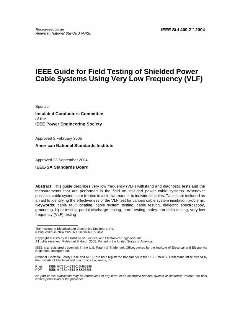
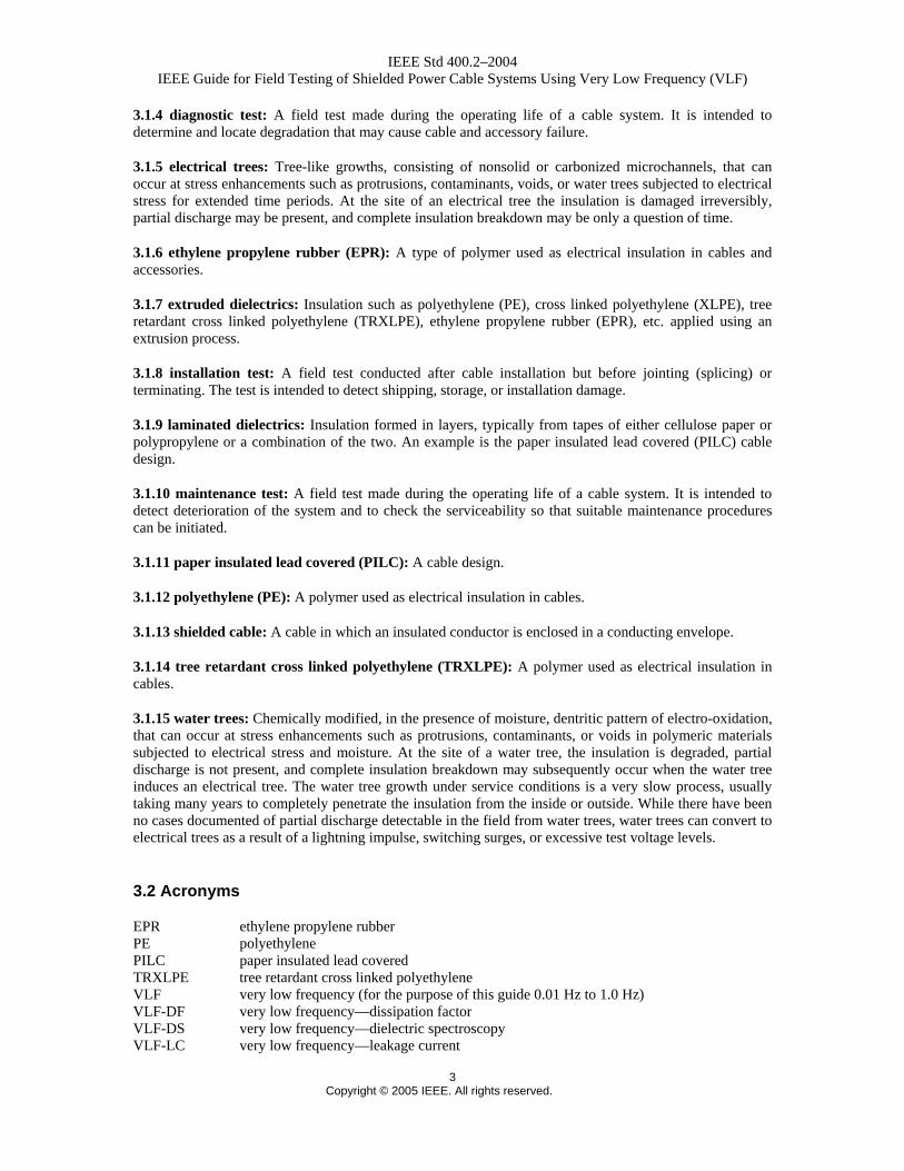
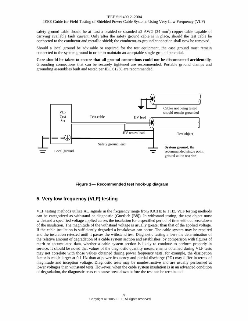
When testing, a single system ground at the test site is recommended (see Figure. 1). The shield or concentric conductor of the cable to be tested is connected to a system ground. If this connection is missing, deteriorated, or has been removed, it must be replaced at this time. A safety ground cable must connect the instrument case with the system ground. If the test instrument is a high voltage device, the
IEEE Std 400.2–2004 IEEE Guide for Field Testing of Shielded Power Cable Systems Using Very Low Frequency (VLF)
5 Copyright © 2005 IEEE. All rights reserved.
safety ground cable should be at least a braided or stranded #2 AWG (34 mm2) copper cable capable of carrying available fault current. Only after the safety ground cable is in place, should the test cable be connected to the conductor and metallic shield; the conductor-to-ground connection shall now be removed.
Should a local ground be advisable or required for the test equipment, the case ground must remain connected to the system ground in order to maintain an acceptable single-ground potential.
Care should be taken to ensure that all ground connections could not be disconnected accidentally. Grounding connections that can be securely tightened are recommended. Portable ground clamps and grounding assemblies built and tested per IEC 61230 are recommended.
Safety ground lead
Local ground
VLF Test Set
System ground, the recommended single point ground at the test site
Test object
Cables not being tested should remain grounded
HV return lead
HV lead Test cable
5. Very low frequency (VLF) testing
VLF testing methods utilize AC signals in the frequency range from 0.01Hz to 1 Hz. VLF testing methods can be categorized as withstand or diagnostic (Gnerlich [B8]). In withstand testing, the test object must withstand a specified voltage applied across the insulation for a specified period of time without breakdown of the insulation. The magnitude of the withstand voltage is usually greater than that of the applied voltage. If the cable insulation is sufficiently degraded a breakdown can occur. The cable system may be repaired and the insulation retested until it passes the withstand test. Diagnostic testing allows the determination of the relative amount of degradation of a cable system section and establishes, by comparison with figures of merit or accumulated data, whether a cable system section is likely to continue to perform properly in service. It should be noted that values of the diagnostic quantity measurements obtained during VLF tests may not correlate with those values obtained during power frequency tests, for example, the dissipation factor is much larger at 0.1 Hz than at power frequency and partial discharge (PD) may differ in terms of magnitude and inception voltage. Diagnostic tests may be nondestructive and are usually performed at lower voltages than withstand tests. However, when the cable system insulation is in an advanced condition of degradation, the diagnostic tests can cause breakdown before the test can be terminated.
Figure 1 — Recommended test hook-up diagram
IEEE Std 400.2–2004 IEEE Guide for Field Testing of Shielded Power Cable Systems Using Very Low Frequency (VLF)
6 Copyright © 2005 IEEE. All rights reserved.
The VLF withstand test methods of cable systems are:
⎯ VLF testing with cosine-rectangular waveform
⎯ VLF testing with sinusoidal waveform
⎯ VLF testing with bipolar rectangular waveform
⎯ VLF testing with alternating regulated positive and negative DC step voltages
Examples of the various waveforms are shown in Annex A.
The VLF diagnostic test methods of cable systems are:
⎯ VLF dissipation factor (tan delta) measurement (VLF-DF)
⎯ VLF differential dissipation factor measurement (VLF-DTD)
⎯ VLF dielectric spectroscopy (VLF-DS)
⎯ VLF loss current harmonics (VLF-LCH)
⎯ VLF leakage current (VLF-LC)
⎯ VLF partial discharge (PD) measurement (VLF-PD)
Field testing techniques frequently employ a combination of diagnostic and withstand test methods. Test methods should be selected based on their ease of operation, operator training requirements, cost/benefit ratio, and the cable system age and condition.
CAUTION
The consequences of a cable system insulation failure during any high-voltage test should be considered prior to undertaking any such test.
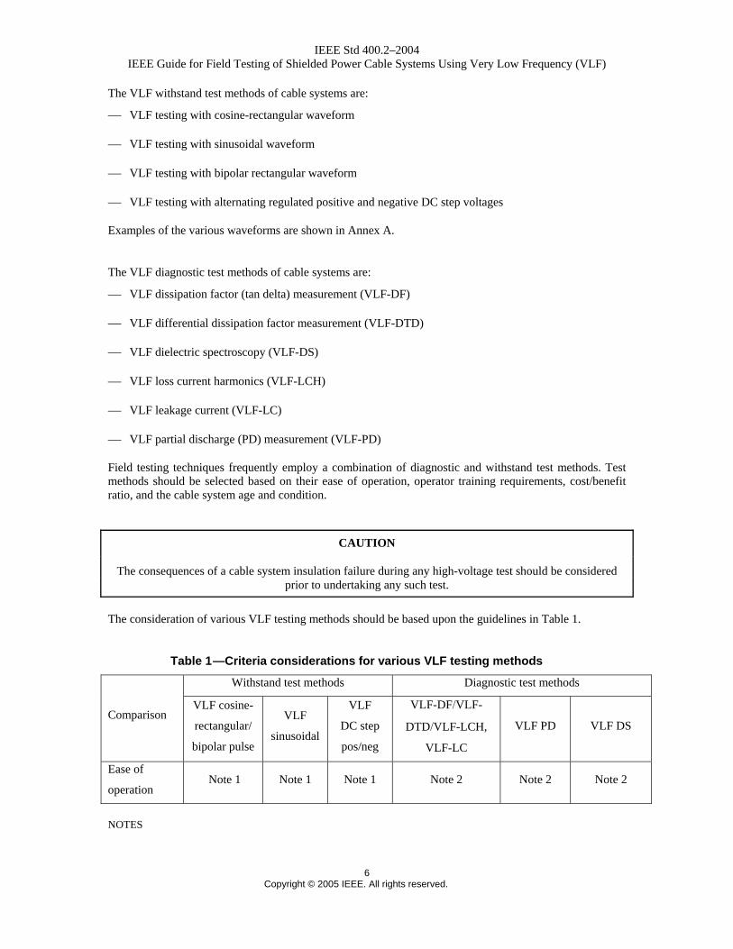
The consideration of various VLF testing methods should be based upon the guidelines in Table 1.
Table 1 —Criteria considerations for various VLF testing methods
Withstand test methods Diagnostic test methods
Comparison VLF cosine-
rectangular/
bipolar pulse
VLF
sinusoidal
VLF
DC step
pos/neg
VLF-DF/VLF-
DTD/VLF-LCH,
VLF-LC
VLF PD VLF DS
Ease of
operation Note 1 Note 1 Note 1 Note 2 Note 2 Note 2
NOTES
IEEE Std 400.2–2004 IEEE Guide for Field Testing of Shielded Power Cable Systems Using Very Low Frequency (VLF)
7 Copyright © 2005 IEEE. All rights reserved.
1— Connect HV power supply and apply voltage of specified magnitude for specified time. Straightforward pass/fail criterion.
2— Connect HV power supply and ancillary equipment, if required, to make diagnostic measurements. Care is needed to eliminate unwanted interference or stray signals.
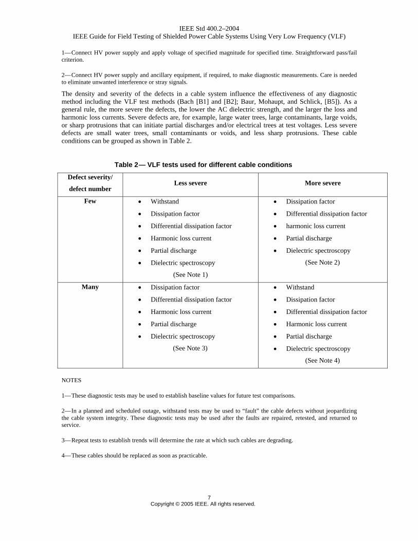
The density and severity of the defects in a cable system influence the effectiveness of any diagnostic method including the VLF test methods (Bach [B1] and [B2]; Baur, Mohaupt, and Schlick, [B5]). As a general rule, the more severe the defects, the lower the AC dielectric strength, and the larger the loss and harmonic loss currents. Severe defects are, for example, large water trees, large contaminants, large voids, or sharp protrusions that can initiate partial discharges and/or electrical trees at test voltages. Less severe defects are small water trees, small contaminants or voids, and less sharp protrusions. These cable conditions can be grouped as shown in Table 2.
Table 2 — VLF tests used for different cable conditions
Defect severity/
defect number Less severe More severe
Few • Withstand
• Dissipation factor
• Differential dissipation factor
• Harmonic loss current
• Partial discharge
• Dielectric spectroscopy
(See Note 1)
• Dissipation factor
• Differential dissipation factor
• harmonic loss current
• Partial discharge
• Dielectric spectroscopy
(See Note 2)
Many • Dissipation factor
• Differential dissipation factor
• Harmonic loss current
• Partial discharge
• Dielectric spectroscopy
(See Note 3)
• Withstand
• Dissipation factor
• Differential dissipation factor
• Harmonic loss current
• Partial discharge
• Dielectric spectroscopy
(See Note 4)
NOTES
1— These diagnostic tests may be used to establish baseline values for future test comparisons.
2— In a planned and scheduled outage, withstand tests may be used to “fault” the cable defects without jeopardizing the cable system integrity. These diagnostic tests may be used after the faults are repaired, retested, and returned to service.
3— Repeat tests to establish trends will determine the rate at which such cables are degrading.
4— These cables should be replaced as soon as practicable.
IEEE Std 400.2–2004 IEEE Guide for Field Testing of Shielded Power Cable Systems Using Very Low Frequency (VLF)
8 Copyright © 2005 IEEE. All rights reserved.
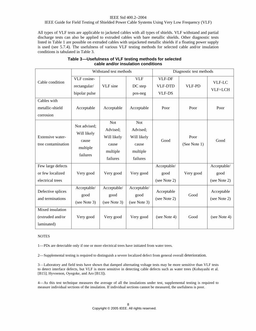
All types of VLF tests are applicable to jacketed cables with all types of shields. VLF withstand and partial discharge tests can also be applied to extruded cables with bare metallic shields. Other diagnostic tests listed in Table 1 are possible on extruded cables with unjacketed metallic shields if a floating power supply is used (see 5.7.4). The usefulness of various VLF testing methods for selected cable and/or insulation conditions is tabulated in Table 3.
Table 3 —Usefulness of VLF testing methods for selected cable and/or insulation conditions
Withstand test methods Diagnostic test methods
Cable condition VLF cosine-
rectangular/
bipolar pulse
VLF sine
VLF
DC step
pos-neg
VLF-DF
VLF-DTD
VLF-DS
VLF-PD VLF-LC
VLF=LCH
Cables with
metallic-shield
corrosion
Acceptable Acceptable Acceptable Poor Poor Poor
Extensive water-
tree contamination
Not advised;
Will likely
cause
multiple
failures
Not
Advised;
Will likely
cause
multiple
failures
Not
Advised;
Will likely
cause
multiple
failures
Good Poor
(See Note 1) Good
Few large defects
or few localized
electrical trees
Very good Very good Very good
Acceptable/
good
(see Note 2)
Very good
Acceptable/
good
(see Note 2)
Defective splices
and terminations
Acceptable/
good
(see Note 3)
Acceptable/
good
(see Note 3)
Acceptable/
good
(see Note 3)
Acceptable
(see Note 2) Good
Acceptable
(see Note 2)
Mixed insulation
(extruded and/or
laminated)
Very good Very good Very good (see Note 4) Good (see Note 4)
NOTES
1— PDs are detectable only if one or more electrical trees have initiated from water trees.
2— Supplemental testing is required to distinguish a severe localized defect from general overall deterioration.
3— Laboratory and field tests have shown that damped alternating voltage tests may be more sensitive than VLF tests to detect interface defects, but VLF is more sensitive in detecting cable defects such as water trees (Kobayashi et al. [B15]; Hyvoenon, Oyegoke, and Aro [B13]).
4— As this test technique measures the average of all the insulations under test, supplemental testing is required to measure individual sections of the insulation. If individual sections cannot be measured, the usefulness is poor.
IEEE Std 400.2–2004 IEEE Guide for Field Testing of Shielded Power Cable Systems Using Very Low Frequency (VLF)
9 Copyright © 2005 IEEE. All rights reserved.
5.1 General VLF testing
5.1.1 VLF test parameters
During a VLF test an electrical tree at the site of an insulation defect is forced to penetrate the insulation. Inception of an electrical tree and channel growth time are functions of test signal frequency and amplitude. For an electrical tree to completely penetrate the insulation during the test duration, VLF test voltage levels and testing time durations have been established for the two most commonly used test signals, the cosine-rectangular and the sinusoidal wave shapes.
The voltage levels (installation and acceptance) are based on most-used practices world-wide of between 2 Uo and 3 Uo, where Uo is the rated voltage for cables rated between 5 kV and 35 kV. The maintenance test level is about 80% of the Acceptance test level. One can reduce the test voltage another 20% if more test cycles are applied (Bach [B2]; Baur, Mohaupt, and Schlick [B5]; Krefter [B16]).
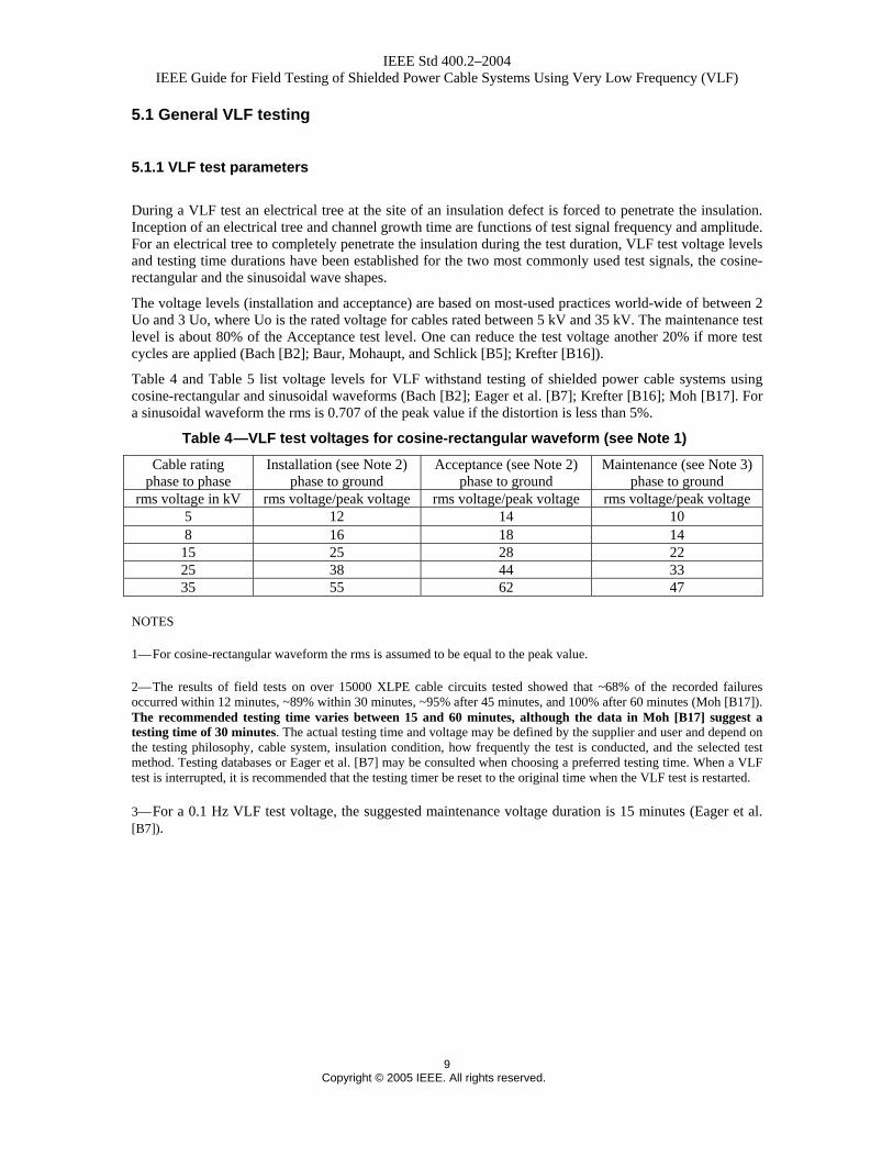
Table 4 and Table 5 list voltage levels for VLF withstand testing of shielded power cable systems using cosine-rectangular and sinusoidal waveforms (Bach [B2]; Eager et al. [B7]; Krefter [B16]; Moh [B17]. For a sinusoidal waveform the rms is 0.707 of the peak value if the distortion is less than 5%.
Table 4 —VLF test voltages for cosine-rectangular waveform (see Note 1)
Cable rating phase to phase
Installation (see Note 2) phase to ground
Acceptance (see Note 2) phase to ground
Maintenance (see Note 3) phase to ground
rms voltage in kV rms voltage/peak voltage rms voltage/peak voltage rms voltage/peak voltage 5 12 14 10 8 16 18 14
15 25 28 22 25 38 44 33 35 55 62 47
NOTES
1— For cosine-rectangular waveform the rms is assumed to be equal to the peak value.
2— The results of field tests on over 15000 XLPE cable circuits tested showed that ~68% of the recorded failures occurred within 12 minutes, ~89% within 30 minutes, ~95% after 45 minutes, and 100% after 60 minutes (Moh [B17]). The recommended testing time varies between 15 and 60 minutes, although the data in Moh [B17] suggest a testing time of 30 minutes. The actual testing time and voltage may be defined by the supplier and user and depend on the testing philosophy, cable system, insulation condition, how frequently the test is conducted, and the selected test method. Testing databases or Eager et al. [B7] may be consulted when choosing a preferred testing time. When a VLF test is interrupted, it is recommended that the testing timer be reset to the original time when the VLF test is restarted.
3— For a 0.1 Hz VLF test voltage, the suggested maintenance voltage duration is 15 minutes (Eager et al. [B7]).
IEEE Std 400.2–2004 IEEE Guide for Field Testing of Shielded Power Cable Systems Using Very Low Frequency (VLF)
10 Copyright © 2005 IEEE. All rights reserved.
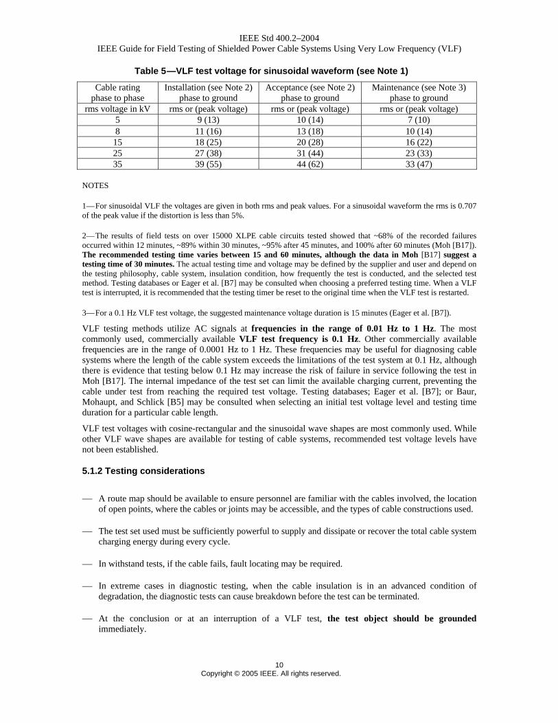
Table 5 —VLF test voltage for sinusoidal waveform (see Note 1)
Cable rating phase to phase
Installation (see Note 2) phase to ground
Acceptance (see Note 2) phase to ground
Maintenance (see Note 3) phase to ground
rms voltage in kV rms or (peak voltage) rms or (peak voltage) rms or (peak voltage) 5 9 (13) 10 (14) 7 (10) 8 11 (16) 13 (18) 10 (14)
15 18 (25) 20 (28) 16 (22) 25 27 (38) 31 (44) 23 (33) 35 39 (55) 44 (62) 33 (47)
NOTES
1— For sinusoidal VLF the voltages are given in both rms and peak values. For a sinusoidal waveform the rms is 0.707 of the peak value if the distortion is less than 5%.
2— The results of field tests on over 15000 XLPE cable circuits tested showed that ~68% of the recorded failures occurred within 12 minutes, ~89% within 30 minutes, ~95% after 45 minutes, and 100% after 60 minutes (Moh [B17]). The recommended testing time varies between 15 and 60 minutes, although the data in Moh [B17] suggest a testing time of 30 minutes. The actual testing time and voltage may be defined by the supplier and user and depend on the testing philosophy, cable system, insulation condition, how frequently the test is conducted, and the selected test method. Testing databases or Eager et al. [B7] may be consulted when choosing a preferred testing time. When a VLF test is interrupted, it is recommended that the testing timer be reset to the original time when the VLF test is restarted.
3— For a 0.1 Hz VLF test voltage, the suggested maintenance voltage duration is 15 minutes (Eager et al. [B7]).
VLF testing methods utilize AC signals at frequencies in the range of 0.01 Hz to 1 Hz. The most commonly used, commercially available VLF test frequency is 0.1 Hz. Other commercially available frequencies are in the range of 0.0001 Hz to 1 Hz. These frequencies may be useful for diagnosing cable systems where the length of the cable system exceeds the limitations of the test system at 0.1 Hz, although there is evidence that testing below 0.1 Hz may increase the risk of failure in service following the test in Moh [B17]. The internal impedance of the test set can limit the available charging current, preventing the cable under test from reaching the required test voltage. Testing databases; Eager et al. [B7]; or Baur, Mohaupt, and Schlick [B5] may be consulted when selecting an initial test voltage level and testing time duration for a particular cable length.
VLF test voltages with cosine-rectangular and the sinusoidal wave shapes are most commonly used. While other VLF wave shapes are available for testing of cable systems, recommended test voltage levels have not been established.
5.1.2 Testing considerations
⎯ A route map should be available to ensure personnel are familiar with the cables involved, the location of open points, where the cables or joints may be accessible, and the types of cable constructions used.
⎯ The test set used must be sufficiently powerful to supply and dissipate or recover the total cable system charging energy during every cycle.
⎯ In withstand tests, if the cable fails, fault locating may be required.
⎯ In extreme cases in diagnostic testing, when the cable insulation is in an advanced condition of degradation, the diagnostic tests can cause breakdown before the test can be terminated.
⎯ At the conclusion or at an interruption of a VLF test, the test object should be grounded immediately.
IEEE Std 400.2–2004 IEEE Guide for Field Testing of Shielded Power Cable Systems Using Very Low Frequency (VLF)
11 Copyright © 2005 IEEE. All rights reserved.
5.2 VLF testing with cosine-rectangular/bipolar pulse waveform
5.2.1 Measurement and equipment
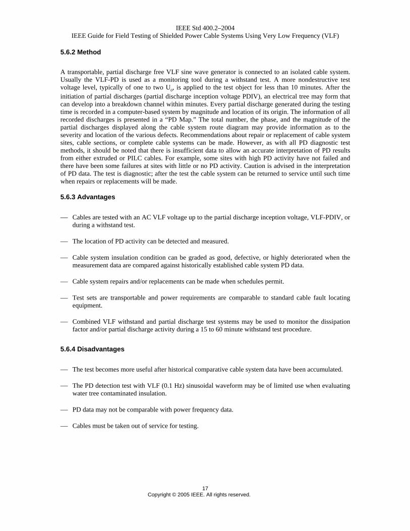
In cosine-rectangular and bipolar pulse waveform VLF test sets, a DC test set forms the high voltage source. A DC-to-AC converter changes the DC voltage to the very low frequency AC test signal. The converter consists of a high voltage inductor and a rectifier. Changing the polarity of the cable system being tested every 5 seconds generates a 0.1 Hz bipolar pulse waveform (see Figure A.1). Cables may be tested in preventive maintenance programs or after outages. Identified faults may be repaired or faulted cable sections replaced.
The measurement of the test voltage should be made with an approved measuring system as described in IEC 60060-3. The peak value of the test voltage should be measured with an overall uncertainty of ± 5% and the response time of the measuring system should not be greater than 0.5 second.
5.2.2 Method
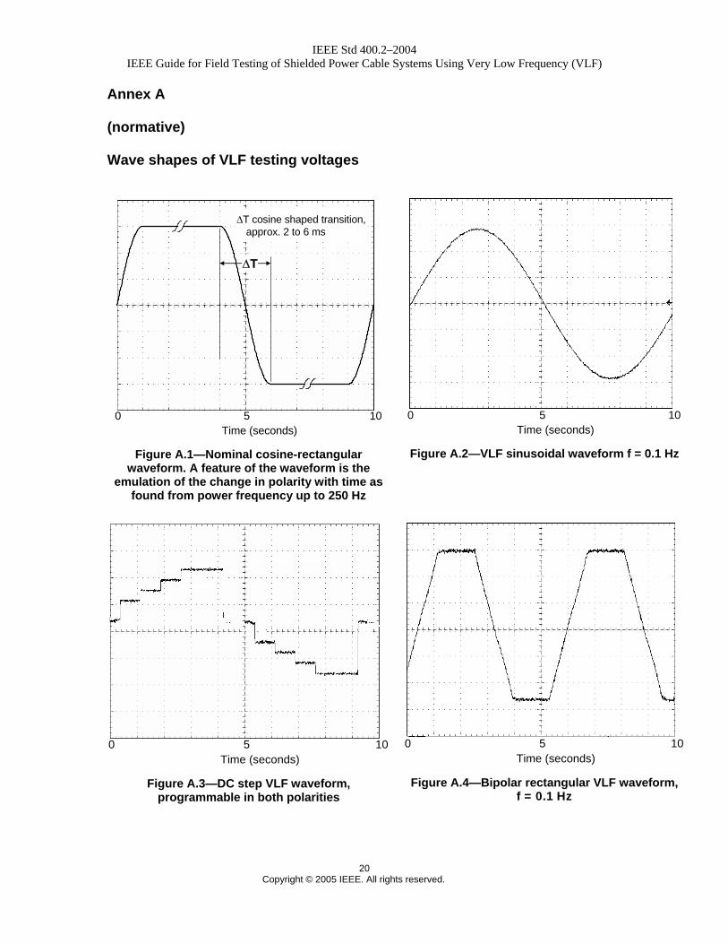
The cable or cable system to be tested is connected to the VLF test set and the cosine-rectangular test voltage raised to a value up to that specified in Table 4. To cause a failure, sinusoidal transitions that are in the power frequency range for the 0.1 Hz cosine-rectangular waveform initiate partial discharges at an insulation defect. These partial discharges may develop the defect into a breakdown channel within minutes. When testing with a bipolar pulse waveform similar to that shown in Figure A.4, the test voltages should be the peak voltages in Table 4. The root-mean-square (rms) value of the bipolar waveform will depend on the wave shape and may not be 0.707 of the peak value.
When the cable or cable system passes the VLF voltage test, the test voltage is regulated to zero and cable and test set are discharged and grounded. The cable or cable system can be returned to service. If a cable or cable system fails the test, the test voltage collapses, as is known from DC high potential testing. The VLF test set is turned off to discharge the cable and test set; the cable is then grounded. The cable fault may be located with standard cable fault locating equipment.
5.2.3 Advantages
⎯ The 0.1 Hz cosine-rectangular waveform has polarity changes similar to those at power frequency. Because of the sinusoidal transitions between the positive and negative polarities, traveling waves are not generated, and because of continuous polarity changes, dangerous space charges are less likely to be developed in the insulation.
⎯ Leakage current can be measured.
⎯ Cables may be tested with an AC voltage approximately three times the rated conductor-to-ground voltage with a device comparable in size, weight, and power requirements to a DC test set.
⎯ The VLF test can be used to test cable systems with extruded and laminated dielectric insulation.
⎯ The VLF test with cosine-rectangular/bipolar pulse waveform works best when eliminating a few defects from otherwise good cable insulation.
IEEE Std 400.2–2004 IEEE Guide for Field Testing of Shielded Power Cable Systems Using Very Low Frequency (VLF)
12 Copyright © 2005 IEEE. All rights reserved.
5.2.4 Disadvantages
⎯ When testing cables with extensive water tree degradation or partial discharges in the insulation, VLF withstand testing alone may not be conclusive. Additional diagnostic tests that measure the extent of insulation losses will be necessary.
⎯ Cables must be taken out of service for testing.
5.3 VLF testing with sinusoidal waveform
5.3.1 Measurement and equipment
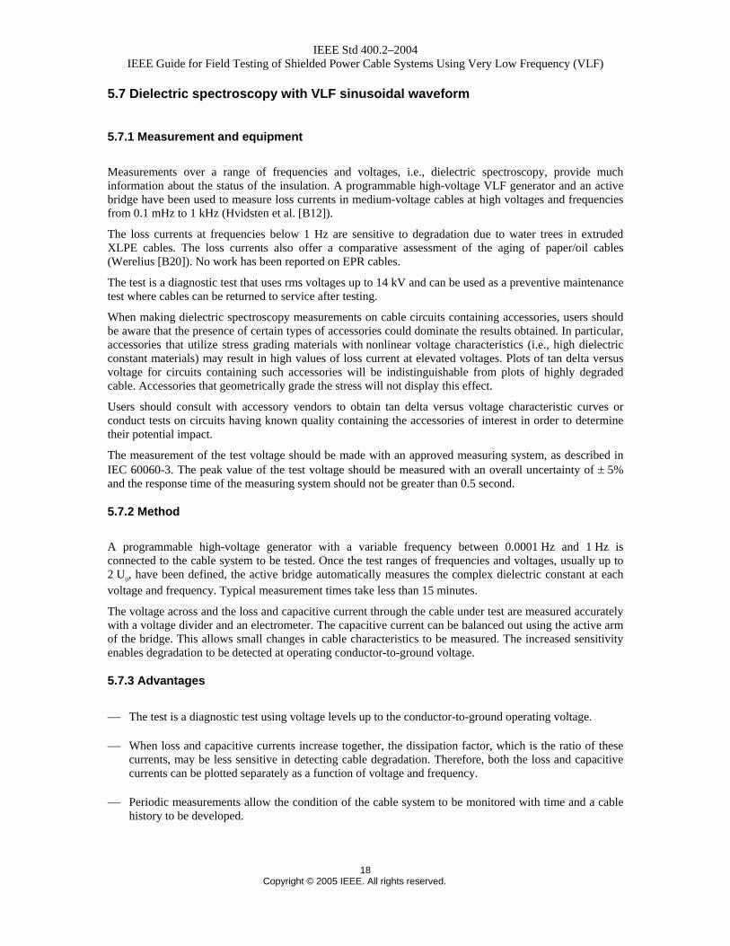
The VLF cable test sets provide true sine wave AC output voltages for testing of cables and capacitive loads (see Figure A.2).
The measurement of the test voltage should be made with an approved measuring system as described in IEC 60060-3. The peak value of the test voltage should be measured with an overall uncertainty of ± 5% and the response time of the measuring system should not be greater than 0.5 second.
5.3.2 Method
The VLF test set is connected to the cable or cable system to be tested and the test voltage raised to a value up to that specified in Table 5. When the cable or cable system passes the VLF voltage test, the test voltage is regulated to zero, the cable or cable system and test set are discharged, and the cable or cable system is grounded.
If a failure occurs during the test, the test voltage collapses, as is known from DC high potential testing. The VLF test set is turned off to discharge the cable and test set. The cable is then grounded. To cause a failure, the local field strength at a defect exceeds the dielectric strength of the insulation, and partial discharges start. The local field strength is a function of the applied test voltage, defect geometry, and space charge. After initiation of partial discharges, the partial discharge channel develops into a breakdown channel within the recommended testing time to cause failure. When a defect has caused breakdown, the latter can then be located with standard fault locating equipment. Cables can be tested in preventive maintenance programs or after outages. Identified faults can be repaired or faulted cable sections replaced. Once a cable passes the VLF withstand test, it may be returned to service.
5.3.3 Advantages
⎯ Because of continuous polarity changes, dangerous space charges are less likely to form in the cable insulation.
⎯ Cables may be tested with an AC voltage approximately three times the conductor-to-ground voltage with a device comparable in size, weight, and power requirements to a DC test set.
⎯ The VLF test can be used to test extruded, laminated, and mixed dielectrics.
⎯ The VLF test with sinusoidal waveform works best when eliminating a few defects from otherwise good cable insulation.
IEEE Std 400.2–2004 IEEE Guide for Field Testing of Shielded Power Cable Systems Using Very Low Frequency (VLF)
13 Copyright © 2005 IEEE. All rights reserved.
⎯ VLF test sets with 0.1 Hz dissipation factor, leakage current, loss harmonic current, or dielectric spectroscopy measurement capability for diagnostically identifying cables with low, medium, or highly degraded cable insulation are available.
⎯ Partial discharge-free VLF high voltage generators for diagnostic testing of cables are also available. These tests are described in 5.5 to 5.7.
⎯ Combined VLF withstand, with dissipation factor and partial discharge measurement capabilities, may be used to monitor the dissipation factor and/or partial discharge activity during a 15 to 60 minute withstand test procedure.
5.3.4 Disadvantages
⎯ When testing cables with extensive water tree damage or partial discharges in the insulation, VLF withstand testing may not be conclusive. Additional diagnostic tests that measure the extent of insulation losses will be necessary (see 5.5 and 5.7).
⎯ Partial discharge test data may not be directly comparable with power frequency data.
⎯ Some data from diagnostic tests may not be comparable with power frequency data.
⎯ At very high test voltage levels and frequencies below 0.01 Hz, space charges might be produced in extruded cable insulation.
⎯ Cables must be taken out of service for testing.
5.4 VLF testing with regulated positive and negative DC voltages
5.4.1 Measurement and equipment
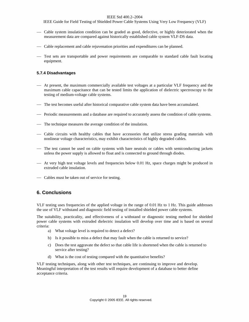
In addition to standard 0.1 Hz sinusoidal very low-frequency test sets, which have been in use for quite some time for VLF testing of electrical machines (IEEE 433), several other test set variations are available to meet specific cable system testing requirements and give specific waveforms (see Figure A.3 and Figure A.4).
For cable systems with mixed extruded and laminated dielectric insulation, high-voltage generators with programmable test voltage waveforms are available:
⎯ 0.1 Hz bipolar waves with defined slew rate
⎯ Regulated DC test voltage with positive and negative polarity of varying time duration
⎯ Programmable step voltage tests with positive and negative voltages
⎯ Positive and negative DC test voltage with superimposed AC signals
In order to evaluate the laminated dielectric insulation portion of the system, leakage current measurements are recorded and compared with historic data or figures of merit. Leakage currents of the extruded dielectric insulation portion are assumed to be negligible.
IEEE Std 400.2–2004 IEEE Guide for Field Testing of Shielded Power Cable Systems Using Very Low Frequency (VLF)
14 Copyright © 2005 IEEE. All rights reserved.
The measurement of the test voltage should be made with an approved measuring system as described in IEC 60060-3. The peak value of the test voltage should be measured with an overall uncertainty of ± 5% and the response time of the measuring system should not be greater than 0.5 second.
5.4.2 Method
The mixed insulation cable system to be tested is connected to the HV terminal of the VLF test set and voltage is then applied to the insulation. The test voltage is regulated to the test voltage level of 3 U0
maximum and leakage current measurements are recorded (see also IEEE Std 400). When the cable system passes the leakage current test/withstand test, the test voltage is regulated to zero and the cable system and test set are discharged and grounded.
The AC portion of the VLF test set is now connected to the cable or cable system to be tested. The test voltage is regulated to the test voltage level of 3 U0 maximum. The recommended testing time is 30 to 60 minutes. When the cable passes the VLF voltage test, the test voltage is regulated to zero and the cable and test set are discharged and grounded.
If a cable system fails the DC or AC test, the test voltage collapses. The test set is turned off to discharge the cable system and test set; the cable fault may then be located with standard cable fault locating equipment. To cause a failure, the local field strength at a cable defect exceeds the dielectric strength of the insulation, and partial discharges start. The local field strength is a function of the applied test voltage, defect geometry, and space charge. After the initiation of partial discharges, an electrical tree may form that can develop into a breakdown channel within minutes. Cable systems can be tested in preventive maintenance programs or after outages. Identified faults may be repaired or faulted cable sections replaced. When a cable system passes the VLF withstand test, it may be returned to service.
5.4.3 Advantages
⎯ This test has merit when new cables with extruded dielectric insulation are spliced into cable systems with mostly laminated insulation.
⎯ Test sets are transportable and power requirements are comparable to standard cable fault locating equipment.
5.4.4 Disadvantages
⎯ In mixed insulation cable systems where service-aged extruded dielectric insulation exposed to moisture is present, the DC portion of the test may shorten the life expectancy of the extruded dielectric.
⎯ Cables must be taken out of service for testing.
5.5 Dissipation factor/differential dissipation factor/leakage current/harmonic loss current tests with VLF sinusoidal waveform
5.5.1 Measurement and equipment
Dissipation factor leakage current and loss current harmonics measurements may be used to monitor aging and deterioration of extruded dielectric cable. A correlation between an increasing 0.1 Hz dissipation factor and a decreasing insulation breakdown voltage level at power frequency has been reported (Bach, Kalkner, Oldehoff [B3]; Hvidsten et al. [B11]). The 0.1 Hz dissipation factor and harmonic loss current are mainly
IEEE Std 400.2–2004 IEEE Guide for Field Testing of Shielded Power Cable Systems Using Very Low Frequency (VLF)
15 Copyright © 2005 IEEE. All rights reserved.
determined by degradation due to water trees of the cable insulation and not by water along conducting surfaces. The measurement of the dissipation factor and harmonic loss current with a 0.1 Hz sinusoidal waveform offer comparative assessment of the aging of PE, XLPE, TRXLPE, and EPR type insulation. The test results permit differentiating between new, defective, and highly degraded cable insulation (Baur, Mohaupt, and Schlick [B5]).
The dissipation factor and harmonic loss current with a 0.1 Hz sinusoidal waveform can be used as a diagnostic test. Cables can be tested in preventive maintenance programs and returned to service after testing. The measurements at VLF can be used to justify cable replacement or cable rejuvenation expenditures.
Commercially available test equipment may combine a programmable high-voltage VLF test generator with a computer-aided dissipation factor test set.
When making tan delta/leakage current/harmonic loss current measurements on cable circuits containing accessories, users should be aware that the presence of certain types of accessories could dominate the results obtained. In particular, accessories that utilize stress grading materials with nonlinear voltage characteristics (i.e., high dielectric constant materials) may result in high values of loss current at elevated voltages. Plots of tan delta versus voltage for circuits containing such accessories will be indistinguishable from plots of highly degraded cable. Accessories that geometrically grade the stress will not display this effect.
Users should consult with accessory vendors to obtain tan delta versus voltage characteristic curves or conduct tests on circuits having known quality containing the accessories of interest in order to determine their potential impact.
The measurement of the test voltage should be made with an approved measuring system, as described in IEC 60060-3. The peak value of the test voltage should be measured with an overall uncertainty of ± 5% and the response time of the measuring system should not be greater than 0.5 second.
5.5.2 Method
A VLF generator with dissipation factor/and harmonic loss current measurement capability is connected to the cable under test. Both cable ends must be accessible for the measurement to ensure that surface leakage currents are kept to a minimum or do not flow through the measurement circuit. The dissipation factors (DF) at U0 and at 2U0 are measured and the differential dissipation factor ∆DF = DF(2U0) − DF(U0) is calculated. The absolute VLF-DF and the VLF-DTD values are used as figures of merit or compared to historical data to grade the condition of the cable insulation as good, defective, or highly deteriorated. If there is a significant increase in DF with increasing voltage, there is no need to raise the voltage to 2U0, as there is a danger of initiating electrical trees in severely damaged insulation.
It must be understood that, for different insulation, installations, and cable types, DF figures of merit can vary significantly from each other. The test works best when comparing present measurements against established historical figures of merit for a particular cable.
5.5.3 Advantages
⎯ The test is a nondestructive diagnostic test using voltage levels up to two times the conductor-to-ground voltage.
⎯ Cable system insulation condition can be graded as good, defective, and highly deteriorated.
⎯ Cable system insulation can be monitored over time and a cable system history developed.
⎯ Cable replacement and cable rejuvenation priorities and expenditures can be planned.
IEEE Std 400.2–2004 IEEE Guide for Field Testing of Shielded Power Cable Systems Using Very Low Frequency (VLF)
16 Copyright © 2005 IEEE. All rights reserved.
⎯ Test sets are transportable and power requirements are comparable to standard cable fault locating equipment.
⎯ Combined VLF withstand, with dissipation factor and partial discharge measurement capabilities, may be used to monitor the dissipation factor and/or partial discharge activity during 15 minute to 60 minute withstand test procedures.
5.5.4 Disadvantages
⎯ Historical comparative cable system data should be available for comparison for the test to be most useful.
⎯ The test cannot be used on cable with bare neutrals or cables with semiconducting jackets unless the power supply is allowed to float and is connected to ground through diodes.
⎯ Periodic measurements and a database are required to accurately assess the condition of cable systems.
⎯ The technique measures the average condition of the insulation.
⎯ Cable circuits with healthy cables that have accessories that utilize stress grading materials with nonlinear voltage characteristics may exhibit characteristics of highly degraded cables.
⎯ Some data from diagnostic tests may not be comparable with power frequency data.
⎯ Cables must be taken out of service for testing.
5.6 PD test with VLF sinusoidal waveform
NOTE—This section describes the PD test with VLF sinusoidal waveform only. PD testing is covered in detail in IEEE P400.3 draft 8. VLF-PD tests should be performed according to IEEE P400.3 draft 8.
5.6.1 Measurement and equipment
PD measurements to monitor aging and degradation of paper-insulated cables have been reported (Baur, Mohaupt and Schlick [B5]; Hetzel and MacKinlay [B10]). The described method is based on the application of a pure, partial discharge free, sinusoidal 0.1 Hz wave to the cable system. The applied voltage of up to two times the rms system line-to-ground voltage may generate partial discharges at insulation defect sites. A traveling wave method may be used to measure the magnitude of PD, locate, and record the partial discharges from the various defect locations in the cable, splices, or terminations. VLF-PD measurements are a diagnostic tool used to detect, in a nondestructive manner, the location and severity of an insulation defect. There may be differences in the PD characteristics measured at VLF and power frequency.
The measurement of the test voltage should be made with an approved measuring system, as described in IEC 60060-3. The peak value of the test voltage should be measured with an overall uncertainty of ± 5% and the response time of the measuring system should not be greater than 0.5 second.
It is recommended that test procedures be followed according to IEC 60885-3 where possible, to aid in consistency of results.
IEEE Std 400.2–2004 IEEE Guide for Field Testing of Shielded Power Cable Systems Using Very Low Frequency (VLF)
17 Copyright © 2005 IEEE. All rights reserved.
5.6.2 Method
A transportable, partial discharge free VLF sine wave generator is connected to an isolated cable system. Usually the VLF-PD is used as a monitoring tool during a withstand test. A more nondestructive test voltage level, typically of one to two U0, is applied to the test object for less than 10 minutes. After the initiation of partial discharges (partial discharge inception voltage PDIV), an electrical tree may form that can develop into a breakdown channel within minutes. Every partial discharge generated during the testing time is recorded in a computer-based system by magnitude and location of its origin. The information of all recorded discharges is presented in a “PD Map.” The total number, the phase, and the magnitude of the partial discharges displayed along the cable system route diagram may provide information as to the severity and location of the various defects. Recommendations about repair or replacement of cable system sites, cable sections, or complete cable systems can be made. However, as with all PD diagnostic test methods, it should be noted that there is insufficient data to allow an accurate interpretation of PD results from either extruded or PILC cables. For example, some sites with high PD activity have not failed and there have been some failures at sites with little or no PD activity. Caution is advised in the interpretation of PD data. The test is diagnostic; after the test the cable system can be returned to service until such time when repairs or replacements will be made.
5.6.3 Advantages
⎯ Cables are tested with an AC VLF voltage up to the partial discharge inception voltage, VLF-PDIV, or during a withstand test.
⎯ The location of PD activity can be detected and measured.
⎯ Cable system insulation condition can be graded as good, defective, or highly deteriorated when the measurement data are compared against historically established cable system PD data.
⎯ Cable system repairs and/or replacements can be made when schedules permit.
⎯ Test sets are transportable and power requirements are comparable to standard cable fault locating equipment.
⎯ Combined VLF withstand and partial discharge test systems may be used to monitor the dissipation factor and/or partial discharge activity during a 15 to 60 minute withstand test procedure.
5.6.4 Disadvantages
⎯ The test becomes more useful after historical comparative cable system data have been accumulated.
⎯ The PD detection test with VLF (0.1 Hz) sinusoidal waveform may be of limited use when evaluating water tree contaminated insulation.
⎯ PD data may not be comparable with power frequency data.
⎯ Cables must be taken out of service for testing.
IEEE Std 400.2–2004 IEEE Guide for Field Testing of Shielded Power Cable Systems Using Very Low Frequency (VLF)
18 Copyright © 2005 IEEE. All rights reserved.
5.7 Dielectric spectroscopy with VLF sinusoidal waveform
5.7.1 Measurement and equipment
Measurements over a range of frequencies and voltages, i.e., dielectric spectroscopy, provide much information about the status of the insulation. A programmable high-voltage VLF generator and an active bridge have been used to measure loss currents in medium-voltage cables at high voltages and frequencies from 0.1 mHz to 1 kHz (Hvidsten et al. [B12]).
The loss currents at frequencies below 1 Hz are sensitive to degradation due to water trees in extruded XLPE cables. The loss currents also offer a comparative assessment of the aging of paper/oil cables (Werelius [B20]). No work has been reported on EPR cables.
The test is a diagnostic test that uses rms voltages up to 14 kV and can be used as a preventive maintenance test where cables can be returned to service after testing.
When making dielectric spectroscopy measurements on cable circuits containing accessories, users should be aware that the presence of certain types of accessories could dominate the results obtained. In particular, accessories that utilize stress grading materials with nonlinear voltage characteristics (i.e., high dielectric constant materials) may result in high values of loss current at elevated voltages. Plots of tan delta versus voltage for circuits containing such accessories will be indistinguishable from plots of highly degraded cable. Accessories that geometrically grade the stress will not display this effect.
Users should consult with accessory vendors to obtain tan delta versus voltage characteristic curves or conduct tests on circuits having known quality containing the accessories of interest in order to determine their potential impact.
The measurement of the test voltage should be made with an approved measuring system, as described in IEC 60060-3. The peak value of the test voltage should be measured with an overall uncertainty of ± 5% and the response time of the measuring system should not be greater than 0.5 second.
5.7.2 Method
A programmable high-voltage generator with a variable frequency between 0.0001 Hz and 1 Hz is connected to the cable system to be tested. Once the test ranges of frequencies and voltages, usually up to 2 U0, have been defined, the active bridge automatically measures the complex dielectric constant at each voltage and frequency. Typical measurement times take less than 15 minutes.
The voltage across and the loss and capacitive current through the cable under test are measured accurately with a voltage divider and an electrometer. The capacitive current can be balanced out using the active arm of the bridge. This allows small changes in cable characteristics to be measured. The increased sensitivity enables degradation to be detected at operating conductor-to-ground voltage.
5.7.3 Advantages
⎯ The test is a diagnostic test using voltage levels up to the conductor-to-ground operating voltage.
⎯ When loss and capacitive currents increase together, the dissipation factor, which is the ratio of these currents, may be less sensitive in detecting cable degradation. Therefore, both the loss and capacitive currents can be plotted separately as a function of voltage and frequency.
⎯ Periodic measurements allow the condition of the cable system to be monitored with time and a cable history to be developed.
IEEE Std 400.2–2004 IEEE Guide for Field Testing of Shielded Power Cable Systems Using Very Low Frequency (VLF)
19 Copyright © 2005 IEEE. All rights reserved.
⎯ Cable system insulation condition can be graded as good, defective, or highly deteriorated when the measurement data are compared against historically established cable system VLF-DS data.
⎯ Cable replacement and cable rejuvenation priorities and expenditures can be planned.
⎯ Test sets are transportable and power requirements are comparable to standard cable fault locating equipment.
5.7.4 Disadvantages
⎯ At present, the maximum commercially available test voltages at a particular VLF frequency and the maximum cable capacitance that can be tested limits the application of dielectric spectroscopy to the testing of medium-voltage cable systems.
⎯ The test becomes useful after historical comparative cable system data have been accumulated.
⎯ Periodic measurements and a database are required to accurately assess the condition of cable systems.
⎯ The technique measures the average condition of the insulation.
⎯ Cable circuits with healthy cables that have accessories that utilize stress grading materials with nonlinear voltage characteristics, may exhibit characteristics of highly degraded cables.
⎯ The test cannot be used on cable systems with bare neutrals or cables with semiconducting jackets unless the power supply is allowed to float and is connected to ground through diodes.
⎯ At very high test voltage levels and frequencies below 0.01 Hz, space charges might be produced in extruded cable insulation.
⎯ Cables must be taken out of service for testing.
6. Conclusions
VLF testing uses frequencies of the applied voltage in the range of 0.01 Hz to 1 Hz. This guide addresses the use of VLF withstand and diagnostic field testing of installed shielded power cable systems.
The suitability, practicality, and effectiveness of a withstand or diagnostic testing method for shielded power cable systems with extruded dielectric insulation will develop over time and is based on several criteria:
a) What voltage level is required to detect a defect?
b) Is it possible to miss a defect that may fault when the cable is returned to service?
c) Does the test aggravate the defect so that cable life is shortened when the cable is returned to service after testing?
d) What is the cost of testing compared with the quantitative benefits?
VLF testing techniques, along with other test techniques, are continuing to improve and develop. Meaningful interpretation of the test results will require development of a database to better define acceptance criteria.
IEEE Std 400.2–2004 IEEE Guide for Field Testing of Shielded Power Cable Systems Using Very Low Frequency (VLF)
20 Copyright © 2005 IEEE. All rights reserved.
Annex A
(normative)
Wave shapes of VLF testing voltages
∆T cosine shaped transition, approx. 2 to 6 ms
Time (seconds)0 105
∆T
Figure A.1—Nominal cosine-rectangular
waveform. A feature of the waveform is the emulation of the change in polarity with time as
found from power frequency up to 250 Hz
Time (seconds)0 105
Figure A.2—VLF sinusoidal waveform f = 0.1 Hz
Time (seconds)0 105
Figure A.3—DC step VLF waveform,
programmable in both polarities
Time (seconds)0 105
Figure A.4—Bipolar rectangular VLF waveform,
f = 0.1 Hz
IEEE Std 400.2–2004 IEEE Guide for Field Testing of Shielded Power Cable Systems Using Very Low Frequency (VLF)
21 Copyright © 2005 IEEE. All rights reserved.
Annex B
(informative)
Bibliography
[B1] Bach, R., “Quervergleich Verschiedener Spannungsarten zur Pruefung von Mittelspannungs-kabelanlagen,” Technical University of Berlin, Annual Report of Research Activities, 1989.
[B2] Bach, R., “Testing and Diagnostic Techniques for Assessing Medium Voltage Service-aged Cables and New Cable Techniques for Avoiding Cable Faults in Future,” CIRED Conference, Brussels, 1995, Paper No. 3.05.1.
[B3] Bach, R., Kalkner, W., Oldehoff, D., “Verlustfaktormessung bei 0.1 Hz an betriebsgealterten PE/VPE Kabelanlagen,” Elektrizitäswirtschaft, Jg. 92, Heft 17/18, pp. 1076–1080, 1993.
[B4] Bahder, G., Katz, C., Eager, G. S., Leber, E., Chalmers, S. M., Jones, W. H., and Mangrum, W. H., “Life Expectancy of Crosslinked Polyethylene Insulated Cables Rated 15 to 35 kV,” IEEE Transactions PES, vol. 100, pp. 1581–1590, April 1981.
[B5] Baur, M., Mohaupt, P., and Schlick, T., “New Results in Medium Voltage Cable Assessment Using Very Low Frequency with Partial Discharge and Dissipation Factor Measurement,” CIRED 17th International Conference on Electricity Distribution, Barcelona, May 12–15, 2003.
[B6] Eager, G. S., Jr., Fryszczyn, B., Katz, C., ElBadaly, H. A., and Jean, A. R., “Effect of D.C. Testing Water Tree Deteriorated Cable and a Preliminary Evaluation of V.L.F. as Alternative,” IEEE Transactions on Power Delivery, vol. 7, no. 3, pp. 1582–1591, July 1992.
[B7] Eager, G. S., Katz, C., Fryszczyn, B., Densley, J., and Bernstein, B. S., “High Voltage VLF Testing of Power Cables,” IEEE Transactions on Power Delivery, vol. 12 no. 2, pp. 565–670, 1997.
[B8] Gnerlich, H. R., “Field Testing of HV Power Cables: Understanding VLF Testing,” IEEE Electrical Insulation Magazine, vol. 11, no. 5, pp. 13–16, Sep./Oct. 1995.
[B9] Groenefeld, P., von Olshausen, R., and Selle, F., “Fehlererkennung und Isolationsgefaehrdung bei der Pruefung Water-tree haltiger VPE-Kabel mit Spannungen unterschiedlicher Form,” Elektrizitaetswirtschaft, Jg. 84, H. 13, pp. 501–505, 1985.
[B10] Hetzel, E., MacKinlay, R. R., “Diagnostic Field Testing of Paper Insulated Lead Covered MV Cables,” JICABLE, 4th International Conference on Insulated Power Cables, Versailles, 1995.
[B11] Hvidsten, S., Faremo, H., Benjaminsen, J. T., and Ildstad, E., “Condition Assessment of Water Treed Service Aged XLPE Cables by Dielectric Response Measurements,” Paper 21–201 presented at CIGRE 8 pp., 2000.
IEEE Std 400.2–2004 IEEE Guide for Field Testing of Shielded Power Cable Systems Using Very Low Frequency (VLF)
22 Copyright © 2005 IEEE. All rights reserved.
[B12] Hvidsten, S., Ildstad, E., Holmgren, B., and Werelius, P., “Correlation between AC Breakdown Strength and Low Frequency Dielectric Loss of Water Tree Aged XLPE Cables,” IEEE Transactions on Power Delivery, vol. 13, no. 1, pp. 40–45, 1998.
[B13] Hyvoenon, P., Oyegoke, B., and Aro, M., “Diagnostics and testing of high voltage cable systems,” Technical report TKK-SJT- 63, High Voltage Institute, Helsinki University of Technology, 19 pp. (available at http://www.hut.fi/Units/HVI/).
[B14] IEEE 100, The Authoritative Dictionary of IEEE Standards Terms, Seventh Edition, New York, Institute of Electrical and Electronic Engineers, Inc.
[B15] Kobayashi, S., Uchida, K., Kawashima, T., Hirotsu, K., Inoue, H., Tanaka, H., and Sakuma, S., “Study on detection for the defects of XLPE cable links,” Proceedings of 1995 Jicable Conference, Paper A.6.3, pp. 151–157.
[B16] Krefter, K-H, “Prüfung zur Beurteilung von Kabelanlagen in Mittelspannungsnetzen,” page 127 cont., VWEW-Verlag, Frankfurt am Main, 1991.
[B17] Moh, S. C., “Very low frequency testing—Its effectiveness in detecting hidden defects in cables,” 2003 CIRED (17th International Conference on Electricity Distribution), Barcelona, Paper 84, May 12–15, 2003.
[B18] Srinivas, N. H. and Bernstein, B. S., “Effect of D.C. Testing on Aged XLPE Insulated Cables with Splices,” JICABLE 91, Paris, France, Paper B.3.1, June 1991.
[B19] Steennis, E. F., Boone, W., and Montfoort, A., “Water Treeing in Service-aged Cables, Experience and Evaluation Procedure,” IEEE Transactions, PES-5, no. 1, pp. 40–46, Jan. 1990.
[B20] Werelius, P., “Power Cable Diagnostics by Dielectric Spectroscopy,” Paper presented at Panel on Diagnostic Measurement Techniques for Power Cables at the 1999 IEEE/PES Transmission and Distribution Conference, New Orleans, April 11–16, 1999.


![NUCLEAR N -Q R EN-DC-346 REV. 2 MANAGEMENT MANUAL ... · [4] IEEE 400.2, “IEEE Guide for Field Testing of Shielded Power Cable Systems Using Very Low Frequency (VLF)” [5] IEEE](https://img.pdfslide.us/doc/110x75/5e6fe716b5d8e42ea06ff4cc/nuclear-n-q-r-en-dc-346-rev-2-management-manual-4-ieee-4002-aoeieee-guide.jpg)