Embed Size (px)
Citation preview
ANSIN41..6
IEEEStd 382-1972
Draft American National Standard
IEEE Trial-Use Guide for Type Test of'Class I Electric Valve Operators forNuclear Power Generating Stations
SponsorJoint Committee on Nuclear Power Standards
of theIEEE Nuclear Science Group
and theIEEE Power Engineering Society
Q Copyright 1972 by
The Institute of Electrical and Electronics Engineers, Inc.
No part Of thiv publication may b reproduced in any form.in an electronic retrieunl system or otherui.se.
without the prior u rittet permission of the huhlisher.
Approved September 20, 1972
IE EE Standards Committee
J. Forster, ChairmanB. 0. Wcinschel, Vice Chairman
S. J. AngelloSaul AronowJack AvinsB. B. BarroW F. K. BeckerRichard BreretonW. H. CookLouis Costrell
G. E. HertigJ. L. loepfinger
0 I W. R. KreusiHarvey LanceB. J. LeonD. T. MichaelJ. D. M. PhelpsR. H. Rose. Ii
S. I. Sherr, Secretary
S. W. RosenthalGustave ShapiroR. M. ShowersP. H. SmithF. G. TimmelL. van RoojiR. V. WachterW. T. Wintringham
NOTICE OF TRIAL USE
Comments on this trial-use standard are welcomed and should be addressed to:Secretary. IEEE Standards Committee. 345 East 47th Street. New York. N.Y.10017.
After a trial-use )erio(d of approximately one year. the Group responsible for thisdocument vill prepare a revision and submit it-to the Standards Committee forapproval as a full-status standard.
Corrected Copy, April 10, 1973A black line () appears in the margin beside those lines that have been corrected.
4
Foreword
(This Foreword is not a part of IEEE Sid 382-1972, Trial-Use Guide for Type Test of Class I Electric Valve Operatorsfor Nuclear Power Generating Stations, ANSI N41.6.)
IEEE Std 323-1971, General Guide for Qualifying Class I Electric Equipment for NuclearPower Generating Stations, describes the basic requirements for equipment qualification. Itrequires that the qualification of Class I electric equipment include the demonstration of thecapability of the equipment, or the components thereof, to meet their performance specificationsunder normal environments and under those conditions that caused and are caused by the designbasis events for the station. Some of the conditions associated with design basis events are notfound in normal service. The capability of equipment under these conditions can be demon-strated by type test.
Each applicant for a construction permit or an operating licenre i reouired to provideassurance that all components are adequate for their service conditions to comply with theAtomic Energy Commission's Code of Federal Regulations (10 CFR 50). Each applicant has theresponsibility to assure himself and others that this guide, if used, is pertinent to his applicationand that the integrated performance of his station is adequate.
The IEEE will maintain this document current with the state of the technology. Comments onthis document and suggestions for additional material are invited. These should be addressed to:
SecretaryIEEE Standards CommitteeInstitute of Electrical and Electronics Engineers345 East 47 StreetNew York, N. Y. 10017
This document was prepared by Subcommittee 2, Equipment Qualification, of the IEEE JointCommittee on Nuclear Power Standards. At the time of approval, the members of theSubcommittee were:
A. J. Simmons, Chairman
L. D. Test, Vice Chairman A. Kaplan, Secretary
J. F. Bates R. F. Edwards T. H. LingJ. T. Bauer C. V. Fields J. C. McCrearyL J. Blasiak R. J. Flaherty, Jr D. J. MeranerE. M. Brown W. J. Folcy C. E. MillerF. J. Campbell J. B. Gardner W. H. SteigelmannF. W. Chandler B. Gregory W. G. StifflerC. E. Corley G. W. Hammond W. A. SzelistowskiW. J. Denkowski A. E. Hilgour I. Villalva
The Working Group of Subcommittee 2, Equipment Qualification, of the IEEE JointCommittee on Nuclear Power Standards had the following membership:
W. J. Denkowski, Chairman
A. J. SimmonsW. H. Stcigelniann
W. A. Szelistowski1. Villalva
At the time it approved this document, the IEEE Joint Committee on Nuclear PowerStatidards had the following mEnibership:
J. C. Russ, ChairmanT. J. Martin, Vice Chairman ' J. T. Boettger, Secretary
R. E. AllenJ. F. BatesR. G. BenhamK. J. BrockwellD. F. Brosnan0. K. BrownS. G. CaslakeF. W. ChandlerE. F. ChelottiC. hi. Chiappetta
R. J. CooneyD. G. FitzgeraldJ. M. GallagherL. M. JohnsonA. KaplanJ. L. HoepfingerV. A. MooreM. I. OlkenE. S. PattersonD. G. PitcherR. A. Saya
A. J. SimmonsJ. H. SmithC. E. StineH. K. StoltD. F. SullivanW. A. SzelistowskiL. D. TestJ. L. VoylesE. C. WenzingerC. J. Wylie
I
'ta
ContentsSECTION PAGE
Part I: Definitions and Tests ...................... 7
1. Scope.................................................................................... 7
2. Definitions. 7
3. Equipment Specifications ..................... 7
4. Type Test Description ....... . . ........................................................ 84.1 General................................................. 84.2 Aging Simulation.. .................. 84.3 Seismic Qualification.......... ............................... . 84.4 Accident or Other Special Environment Simulation . ................................ :.. 84.5 Measurements and Tests ........................................... 8
4.5.] Measurment Categories ..................................... 84.5.2 Test Sequence ................................... .. 9
4.5.2.1 Normal Condition Load Test ..................................... 94.5.2.2 Design Basis Accident Load Test ....................................... 94.5.2.3 Post Design Basis Accident Load Test .................................. 9
4.6 Inspection ............................. 9
5. Documentation .......... .............................................................. 95.1 General .................... 95.2 Type Test Data .................. ...................................... 9
6. Standards References.. .................. ........................ ............. 0 .... 10
Part 11: Procedure for Aging Sim ulation .................................................. 10
Part Ili: Design Basis Accident Environment Simulation for 1-'V11 and BWR . ............... 11
Part IV: Design Basis Accident Environment Simulation for an HTGR ... .... .. 14
TABLESTable 1 Test Conditions for Pressurized Water Reactors .12Table 2 Test Conditions for Boiling Water Reactors ..................................... 12Table 3 Test Conditions for High-Temperature
Gas-Cooled Reactors .............. 16
FIGURESFig 1 Test Chamber Profile for Accident Environment Simulation ........................ 13Fig 2 Temperature and Pressure History for Environment Simulation
of HTGR Containment Atmosphere Response Following a HotHelium Blowdown Into Containment ....... ............ ................ 14
Fig 3 Temperature and Pressure History for Environment Simulationof HTGR Containment Atmosphere Response Following a SteamLine Rupture Inside the Containment ........................................... .15
Draft American National Standard
IEEE Trial-Use Guide for Type Test ofClass I Electric Valve Operators forNuclear Power Generating Stations
Part I: Definitions and Tests
1. Scope
This guide provides direction Ilishing a type test that will yield diverify that Class I electric valve opfnuclear power generating stationstheir design basis performance requi
2.. Definitions
The definitions in this section estEmeanings of words in the context ofin this guide.
class I electric equipment. The elect]ment that is essential to the safe and isolation of the reactor or whosedamage could result in significantradioactive materials.
containment. That portion of the eisafety features designed to act as-thebarrier, after the reactor systemboundary, to prevent the release, evconditions of a reactor accident, of iable quantities of radioactive materi;a controlled zone.
design basis events. Postulated eventhe design to establish the perfornquirements of the structures and sys
design life. The time during whichtory performance can be expected foiic set of service conditions upon whimargins are based.
electric valve operator. An electricmechanism for opening and closinfincluding all electric and mechan:
ror estab-
ponents that are integral to the mechanismand are required to operate and control valveaction.
ata which installed life. The interval from installation to-rators forcan meet removal, during which the equipment or com-irements. ponent thereof may be subject to design ser-
vice conditions and process demands.
NOTE: A valve operator may have an installed life of40 years with certain components (seals and lubricants)changed periodically; thus, the installed life of the com-ponents would be less than 40 years.
operating cycle. The complete sequence ofiblish the operations that occur during a response to atheir use demand function.
sample valve operator. A production valvehc equip operator type tested to obtain data that are
failure or valid over a range of sizes and for the specific
release of services.NOTE: All salient factors must be shown to be common
to the sample valve operator and to the intended serviceagineered valve operator. Commonality of factors such as materials
pr l of construction, lubrication, mechanical stresses andprcpa clearances, manufacturing processes, and dielectric prop-pressure erties may be established by specification, test, or an-
,en under alyses.
inaccept-al beyond
3. Equipment Specificationsts used inaance re- The manufacturer's equipment specifica-tems. tions shall include the following:satisfac- (1) Valve operator performance character-
r at sec- istics under defined plant normal, test, design~ a sdpe.cif- basis event, and post design basis event condi-chi design tis
(2) The range of voltage, frequency, andpowered environmental conditions, including seismic
g a valve, forces, under which the valve operator willical corm- provide rated mechanical force
7
ANSIN41.6 GUIDE FOR TYPE TEST OF CLASS I ELECTRIC VALVE
(3) The mounting configuration for thevalve operator
(4) Preventive maintenance schedule for lu-bricants, seals, and other components for theinstalled life of the valve operators
(5) The design life of the valve operator(6) Control and indicating devices con-
tained on the valve operator
4. Type Test Description
4.1 General. The type test shall demonstratethat the performance characteristics of thevalve operator adhere to the equipment speci-fications. One or more sample valve operatorsshall be constructed using normal manu-facturing processes and then be subjected tothe test program described herein. The test forthe sample valve operator shall consist ofsubjecting it to the following sequence ofconditions to simulate the design basis serviceconditions of the operator, that is, (1) aging,(2) seismic, and (3) accident or other specialenvironment as applicable.
NOTE: Valve operators installed outside the con-lainnient will not be exposed to the same environmentalconditions during an accident as are those installedwithin the containment.
No maintenance shall be performed duringthe type test.
4.2 Aging Simulation. The aging procedureshall simulate the effects of environment (forexample, temperature, humidity, nuclearradiations, and contaminants), voltage stress,and mechanical stresses and wear (startingforces, vibration, and driven load). A proce-dure for aging simulation is suggested in PartII.
4.3 Seismic Qualification. The valve operatorshall be qualified for seismic conditions inaccordance with the requirements set forth inIEEE Std 344-1971, Trial-Use Guide for Seis-mic Qualification of Class I Electric Equip-ment for Nuclear Power Generating Stations.
4.4 Accident or Other Special EnvironmentSimulation. The valve operator shall bemounted in a test chamber in a position andmanner that simulate its installation in actu-al use.
NOTE: Analysis may be used to justify testing in oneposition to represent multiple installation positions.
Means shall be provided for electrically ener-gizing the valve operator, applying simulatedfunctional loads during test, and exposing itto environmental conditions (for example,temperature, pressure, moisture, nuclear radi-ations, chemical solutions, jet forces, andchemical composition of the ambient) thatsimulate those to which the intended servicevalve operator is expected to be exposed dur-ing and following design basis accidents. Thevalve operator shall be exposed to appropriatenuclear radiation prior to or during test cham-ber tests. Typical procedures for accident en-vironment simulation are suggested in PartsIII and IV; however, the values of the envi-ronmental parameters presented in Parts IIIand IV may be different for various plantdesigns.
4.5 Measurements and Tests. The test mea-surements shall be made with equipment thatprovides adequate resolution for detectingmeaningful changes in the parameters. Thetime interval between measurements shall besuch as to obtain the response of each para-meter.
4.5.1 Measurement Categories. The mea-sured parameters shall be classified accordingto their general nature into one of five cate-gories as follows:
Category I - Environment. Tem-perature, total pressure, and vapor pressurewithin the test chamber
Category II - Power and Cycle Time.Frequency, current, voltage, power to thevalve operator, time duration of the operatingcycle, and simulated load
Category III - Fluid Characteristics.Concentration of chemical constituents andconcentration in fluids injected into the testchamber plus the flow rate of fluids injectedinto the test chamber
Category IV - Radiological Features.Nuclear radiation data, including energytype, energy level, exposure rate, and inte-grated dose
Category V - Electrical Resistance. In-sulation resistance of the electrical com-ponents of the valve operator
;I
8
OPERATORS FOR NUCLEAR POWER GENERATING STATIONSIEEE Sd382-1972
4.5.2 Test Sequence. The test sequence.shall properly cycle all the operations associ-ated with normal conditions, design basisaccident conditions, and post- design basisaccident conditions.
4.5.2.1 Normal Condition Load Test.The proper sequencing of this test shall be asfollows:
(1) Age the valve operator to an appropriatedegree in accordance with the recommenda-tions in Part II. Seismically qualify as speci-fied in IEEE Std 344-1971. Establish thenormal environmental conditions which existprior to the design basis accident. Recordappropriate Category I, II, and V measure-ments.
(2) Exercise the valve operator through one,'complete operating cycle. Record appropriateCategory I and II measurements.
(3) After the operating cycle has been com-pleted, record Category V measurements.
4.5.2.2 Design Basis Accident Load Test.The proper sequencing of this test shall be asfollows:
(1) Irradiate the sample valve operator to atleast 50 percent of the total integrated doselevel expected during the period of the designbasis accident.
NOTE: This irradiation may be combined with thatperformed as part of the aging simulation.
Record Category IV measurements.(2) Inject fluids (for example, steam, gases,
liquid jets, chemical solution sprays) into thetest chamber as required to simulate the timevariations of the design basis accident envi-ronmental conditions as described in Parts IIIand IV. Record Category I, II, and III mea-surements at appropriate intervals through-out this test.
(3) When the environmental conditionsreach peak values, exercise the valve operatorthrough one complete operating cycle at de-sign basis accident loading conditions. Recordappropriate Category I, II, and V measure-ments.
(4) Before the pressure within the testchamber falls below 90 percent of its peakvalue, exercise the valve operator through onecomplete cycle. Record appropriate CategoryI, II, and V measurements.
(5) Repeat steps. (2) through (4) for therequired number of environmental transients.
4.5.2.3 Post Design Basis Accident LoadTest. The proper sequencing of this test shallbe as follows:
(1) After the environmental transient testsassociated with the design basis accident havebeen completed, adjust the conditions in thetest chamber so as to simulate the post designbasis accident conditions as described in PartsIII and IV. Record the appropriate CategoryI, III, and V measurements at suitable inter-vals.
(2) Exercise the valve operator through acomplete cycle and repeat at specified inter-vals. Record Category II measurements.
(_ Establish th- *Fasiamenal conditionsX ulnr-.cai'arAl repeat' the tests stipulated in
(4) Irradiate the valve operator, as re-quired, to meet the requirements of Part II toattain the total integrated dose level expectedduring the design basis accident.
(5) Repeat step (3).
4.6 Inspection. Upon completion of the tests,the valve operator shall be dismantled andvisually inspected. The condition of the wind-ings, bearing, lubricants, auxiliary contacts.wiring, gear drive trains, drive linkages, andother related components shall be recorded.
. Documentation
5.1 General. The type test documentationshall be sufficient to verify that the equipmentmeets its specified performance requirements.
5.2 Type Test Data. Type test data used todemonstrate the qualifications of the equip-* :e ti; be-pertinent to the application andogla winid in an auditable form. The type testdata shall include:
(1) Identification of equipment(2) Equipment specifications(3) Test specification and objective(4) Test results(for each test)
(a) Equipment tested(b) Test facility and instrumentation(c) Test procedure(d) Test data and accuracy(e) Inspection results(f) Conclusions
(5) Supporting data(6) Approved signature and date
9
ANSIN41.6 CUIDE FOR TYPE TEST OF CLASS I ELECTRIC VALVE
6. Standards References
The following IEEE Standards were used asreferences in preparing this guide and areuseful in the interpretation of its meaning.
IEEE Std 112A-1964, Test Procedure forPolyphase Induction Motors and Generators
IEEE Std 117-1956, Test Procedure for Eval-uation of Systems of Insulating Materials forRandom-Wound Electric Machinery
IEEE 323-1971, General Guide for QualifyingClass I Electric Equipment for Nuclear PowerGenerating Stations
IEEE 334-1971, Trial-Use Guide for TypeTests of Continuous-Duty Class I Motors In-stalled Inside the Containment of NuclearPower Generating Stations
IEEE 344-1971, Trial-Use Guide for SeismicQualification of Class I Electric Equipmentfor Nuclear Power Generating Stations
I
Part II: Procedurefor Aging Simulation
The normal operating environment towhich the valve operator is subjected duringits period of installed life consists of two majorparts: (1) exposure to nuclear radiations, and(2) exposure to temperature, humidity, and, insome instances, to an ambient atmospherecomposition different from standard air. Inaddition. normal service usage and/or theperformance of routine testing during its in-stalled life produces an aging of the valveoperator.
NOTE: It is recognized that limited technical informa-tion is available regarding aging of electromechanicalequipment components, including the effects of simulta-neous nuclear radiation, temperature, and humidity ex-posures. There is likewise little information on how toproperly perform accelerated humidity and radiationaging.
The normal operating environment and thetest procedures are different in the variousspecific plant applications. A typical set ofaging procedures is presented in the followingparagraphs, but the user has the responsi-bility for determining that they are applicablefor the plant application where the valveoperator is to be used. Also, it must be recog-nized that the exposures to be simulated occursimultaneously during the plant in-serviceperiod, and thus some added conservatismshould be used if a sequential set of agingexposures is employed.
1. Exposure to Nuclear Radiations
The sample valve operator shall be uni-formly exposed to a source of gamma radi-
ation (such as cobalt 60) for such time as toyield an equivalent exposure of 0.1 Mradequivalent air dose per year for 40 years.
NOTES: () The volume occupied by the actuator shallreceive an isotropic flux of gamma radiation such that ifthe volume contained air this radiation dose would result.
(2) If nuclear rdiation exposure tests and analyses ofthe various materials used in the valve operator showthat. at the design basis levels. both direct damage to anymaterials and the evolution of radiation-produced sub-stances are negligible, then an actual radiation exposureis not necessary as part of the type test. All possiblecombined effects which may be produced by the nuclearradiation exposure acting in concert with other envi.on-mental exposures shall be considered.
2. Exposure to Temperature and Humidity
The sample valve operator shall be exposedto the equivalent of 40 years at a temperatureof 1400F and 55 percent relative humidity.(See EEE Std 117 - 1956, Test Procedure forEvaluation of Systems of Insulating Materialsfor Random-Wound Electric Machinery.)
3. Operating Cycles
The sample valve operator shall be cycled(from the full open to the full closed and backto the full open position) under a load equiva-lent to the driven load in the plant (or its ratedload) for the anticipated number of operatingcycles over a 40 year insLalled life. The test.shall ecompass a minimum of 500 operatingcycles.
Mr
.
10
0 . I
OPERATORS FOR NUCLEAR POWER GENERATING STATIONS
Part III: Design BasisAccident Environment Simulation,
for PWR and BWR
IEEE Std382-1972
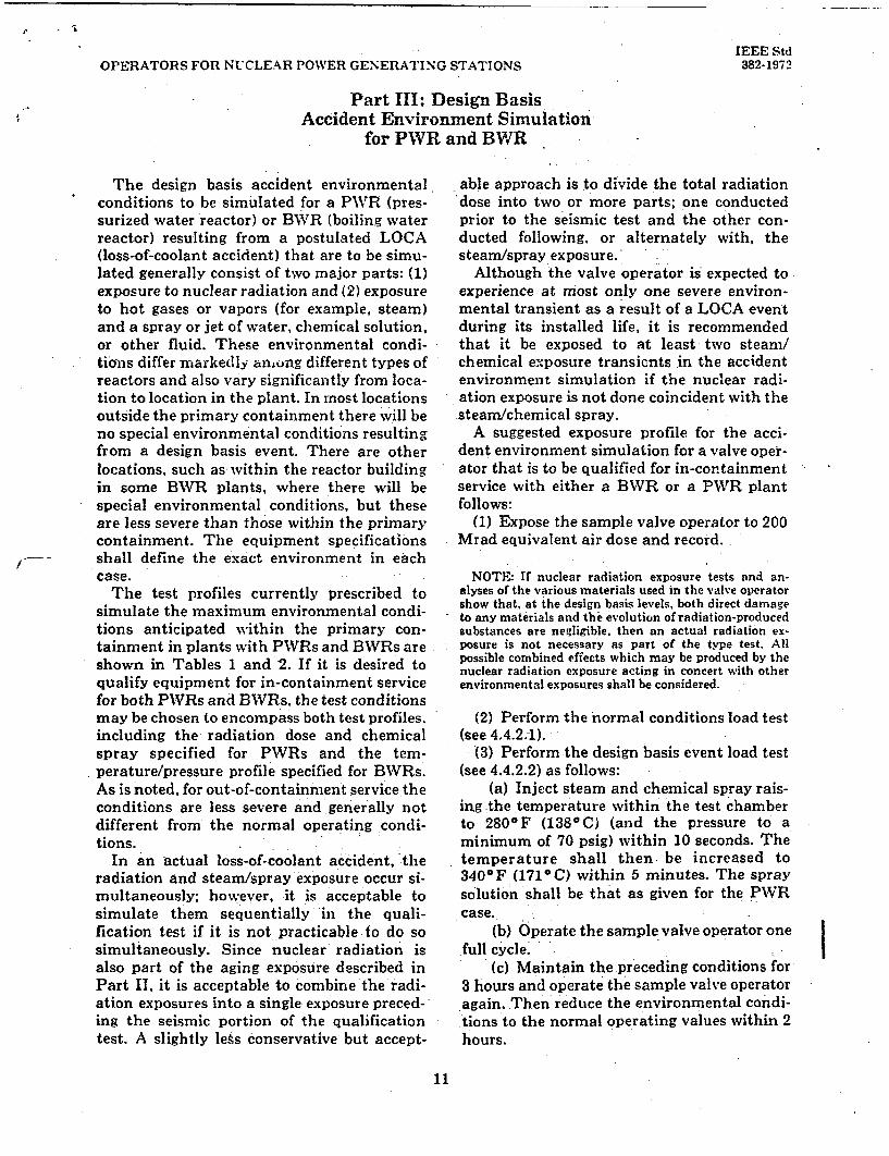
The design basis accident environmentalconditions to be simulated for a PWR (pres-surized water reactor) or BWR (boiling waterreactor) resulting from a postulated LOCA(loss-of-coolant accident) that are to be simu-lated generally consist of two major parts: (1)exposure to nuclear radiation and (2) exposureto hot gases or vapors (for example, steam)and a spray or jet of water, chemical solution,or other fluid. These environmental condi-tions differ riarkedly anIung different types ofreactors and also vary significantly from loca-tion to location in the plant. In most locationsoutside the primary containment there will beno special environmental conditions resultingfrom a design basis event. There are otherlocations, such as within the reactor buildingin some BR plants, where there will bespecial environmental conditions, but theseare less severe than those within the primarycontainment. The equipment specificationsshall define the exact environment in eachcase.
The test profiles currently prescribed tosimulate the maximum environmental condi-tions anticipated within the primary con-tainment in plants with PWRs and BWRs areshown in Tables 1 and 2. If it is desired toqualify equipment for in-containment servicefor both PWRs and BWRs, the test conditionsmay be chosen to encompass both test profiles.including the radiation dose and chemicalspray specified for PWRs and the tem-perature/pressure profile specified for BWRs.As is noted, for out-of-containment service theconditions are less severe and generally notdifferent from the normal operating condi-tions.
In an actual loss-of-coolant accident, theradiation and steam/spray exposure occur si-multaneously; however, it is acceptable tosimulate them sequentially in the quali-fication test if it is not practicable to do sosimultaneously. Since nuclear radiation isalso part of the aging exposure described inPart II, it is acceptable to combine the radi-ation exposures into a single exposure preced-ing the seismic portion of the qualificationtest. A slightly lets conservative but accept-
able approach is to divide the total radiation'dose into two or more parts; one conductedprior to the seismic test and the other con-ducted following, or alternately with, thesteam/spray exposure.
Although the valve operator is expected to.experience at most only one severe environ-mental transient as a result of a LOCA eventduring its installed life, it is recommendedthat it be exposed to at least- two steam/chemical exposure transients in the accidentenvironment simulation if the nuclear radi-ation exposure is not done coincident with thesteam/chemical spray.
A suggested exposure profile for the acci-dent environment simulation for a valve oper-ator that is to be qualified for in-containmentservice with either a BWR or a PWR plantfollows:
(1) Expose the sample valve operator to 200Mrad equivalent air dose and record.
NOTE: If nuclear radiation exposure tests and an-alyses of the various materials used in the valve operatorshow that, at the design basis levels, both direct damageto any materials and the evolution of radiation-producedsubstances are negligible, then an actual radiation ex-posure is not necessary as part of the type test. Allpossible combined effects which may be produced by thenuclear radiation exposure acting in concert with otherenvironmental exposures shall be considered.
(2) Perform the normal conditions load test(see 4.4.2.-1).
(3) Perform the design basis event load test(see 4.4.2.2) as follows:
(a) Inject steam and chemical spray rais-ing the temperature within the test chamberto 2801F (1381C) (and the pressure to aminimum of 70 psig) within 10 seconds. Thetemperature shall then be increased to3401F (171'C) within 5 minutes. The spraysolution shall be that as given for the PWRcase.
(b) Operate the sample valve operator onefull cycle.
(c) Maintain the preceding conditions for3 hours and operate the sample valve operatoragain. Then reduce the environmental condi-tions to the normal operating values within 2hours.
I
11
ANSIN41.6 GUIDE FOR TYPE TEST OF CLASS I ELECTRIC VALVE
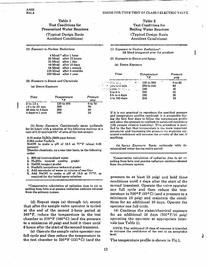
Table 1Test Conditions for
Pressurized Water Reactors
(Typical Design BasisAccident Conditions)
Table 2Test Conditions for
Boiling Water Reactors(Typical Design BasisAccident Conditions)
(1) Exposure to Nuclear Radiations
4 Mrad after 1 hour20 Mrad after 12 hours24 Mrad after 1 day40 Mrad after 10 days55 Mrad after 1 month
110 Mrad after 6 months150 Mrad after 1 year
(2) Exposure to Steam and Chemicals
(a) Steam Exposure
(1) Exposure to Nuclear Radiations26 Mrad integrated over the accident
(2) Exposure to Steam and Spray
(a) Steam Exposure
Time Temperature Pressuree--. - --F psig
I
--- en . - - -- 135 to 280-a Vi-iWomin 280 to 340- . . or Z:~m 4 3- ,. 340
'3 to 6 h 3206 h to 4 days 2504 to 100 days 200
0 to 626240402510Time
0 to 10 s1 l0s to 30 min30 min to 4 days4 days to 1 year
TemperatureOF
120 to 300300250200
Pressurepsig
0 to 70703010
(b) Spray Exposure. Continuously spray uniformlyfor 24 hours with a solution of the following makeup at arate of 0.16 (gal/min)/ft2 of area of the test sample:
0.28 molar H3BO3 (3000 ppm boron)0.064 molar Na2 S2 03NaOH to make a pH of 15 at 77'F (about .5Spercent)Dissolve chemicals, on a one-liter basis, in the followingorder:
1. 600-ml demineralized water2. H3BO3 (special quality grade)3. NaOH (reagent grade)4. Na2S20s (anhydrous technical grade)5. Add remainder of water to volume of one liter6. Add NaO-1 to make a pH of 10.5 at 77%F, as
required for the initial spray solution
If it is not practical to reproduce the specified pressureand temperature profiles combined, it is acceptable dur-ing the first four days to follow the temperature profileand allow the pressure to conform to saturated conditions(100 percent relative humidity). This procedure is justi-fied by the fact that temperature is the more importantparameter and increasing the pressure to maintain sat-urated conditions) will increase the severity of the test, itanything.
(b) Spray Exposure. Spray uniformly with de-mineralized water during entire period.
'Conservative calculation of radiation dose to air re-sulting from beta and gamma radiation emitters releasedfrom the primary system.
pressure to at least 25 psig) and hold theseconditions until 4 days after the start of thesecond transient. Operate the valve operator*onc -full cycle and then reduce the tem-perature to 2000F (930C) (and a pressure to aminimum 10 psig) and maintain the condi-tions for an additional 10 days. Operate theoperator one full cycle.
(4) Continue the steam/chemical exposurefor an additional 16 days (200 F/10 psig)operating the operator at appropriate inter-vals (see Table 1).
NOTE: The additional 16 days of exposure is intendedto increase the confidence of the test to an acceptablelevel.
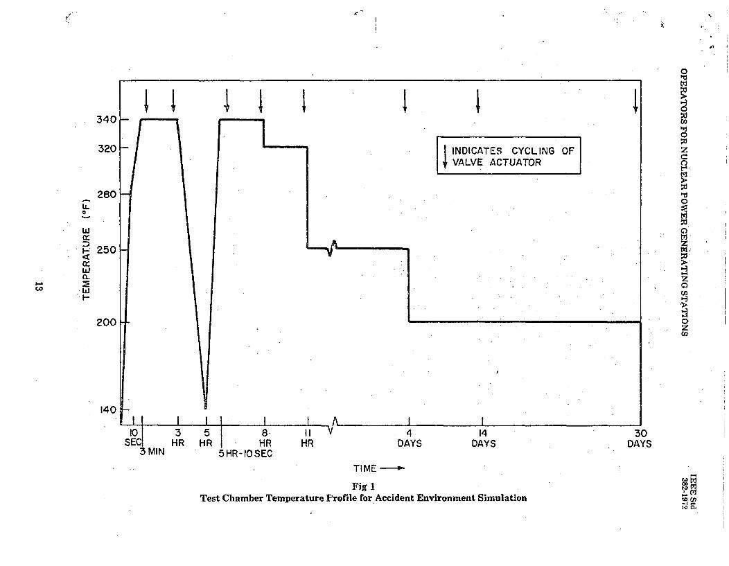
The temperature profile is shown in Fig 1.
Conservative calculation of radiation dose to air re-sulting from beta and gamma radiation emitters releasedfrom the primary system.
(d) Repeat steps (a) through (c), exceptthat after the sample valve operator is cycledat the end of the second 3-hour period at340'F, reduce the temperature in the testchamber to 3201F (1600°C) (and the. pressureto a minimum 40 psig) and hold it there until6 hours after the start of the second transient.
(e) Operate the sample valve operator onefull cycle and then reduce the temperature inthe test chamber to 2501F (1210C) (and the
12
';
340
320
280L0
wa:
250
wa.
w ~ w
200
140
0
It0
0o
C
4
0
t1I
zOl
0
0O
0
2:
CD
30DAYS
TI ME -
Fie ITest Chamber Temperature Profile for. Accident Environment Simulation -
w
I -
ANSIN41.6 GUIDE FOR TYPE TEST OF CLASS I ELECTRIC VALVE
Part IV: Design Basis AccidentEnvironment Simulation for an HTGR
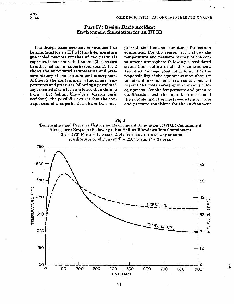
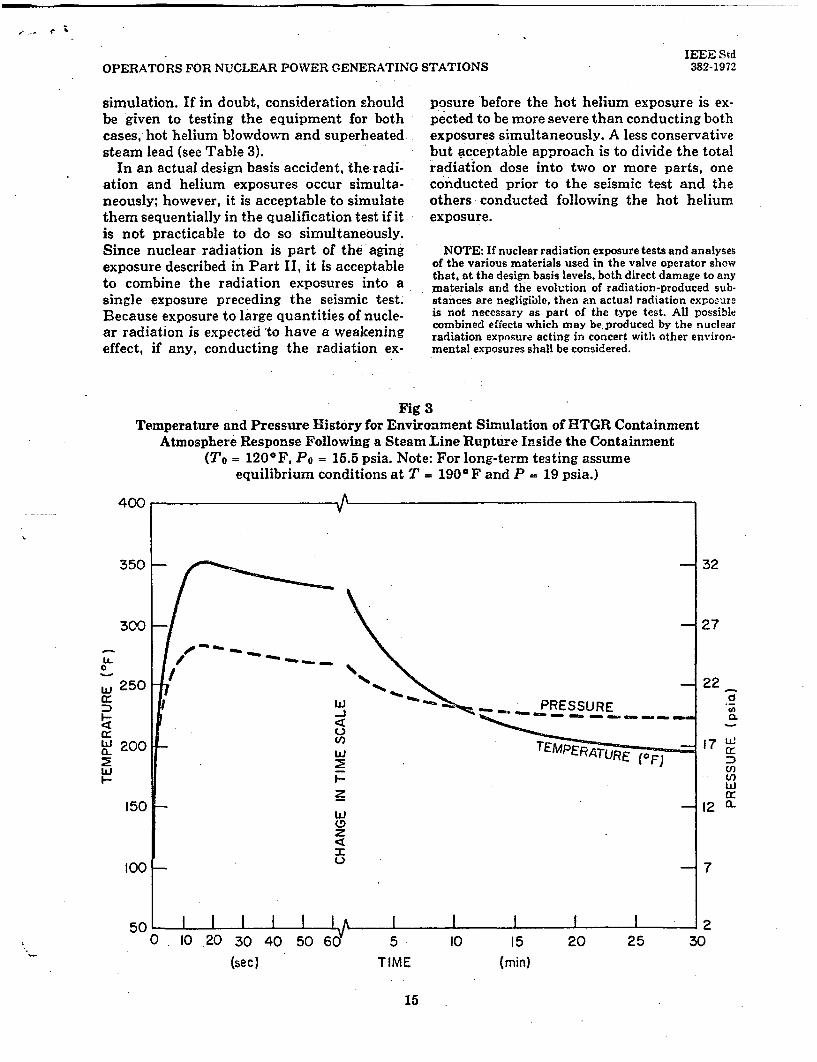
The design basis accident environment tobe simulated for an HTGR (high-temperaturegas-cooled reactor) consists of two parts: (1)exposure to nuclear radiation and (2) exposureto either helium (or superheated steam). Fig 2shows the anticipated temperature and pres-sure history of the containment atmosphere.Although the containment atmosphere tem-peratures and pressures following a postulatedsuperheated steam leak are lower than the onefrom a h3o helium blowdo-wn (design basisaccident), the possibility exists that the con-sequences of a superheated steam leak may
present the limiting conditions for certainequipment. For this reason, Fig 3 shows thetemperature and pressure history of the con-tainment atmosphere following a postulatedsteam line rupture inside the containment,assuming homogeneous conditions. It is theresponsibility of the equipment manufacturerto determine which of the two conditions willpresent the most severe environment for hisequipment. For the temperature and pressurequalification test the manufacturer shouldthen decide upon the most severe temperatureand pressure conditions for the environment
Fig 2Temperature and Pressure History for Environment Simulation of HTGR Containment
Atmosphere Response Following a Hot Helium Blowdown Into Containment(To = 1200F, Po = 15.5 psia. Note: For long-term testing assume
equilibrium conditions at T = 250° F and P = 37 psia.)
750
650
550
LL
, 450a:
aE 350
w
250
150
50
62
52
42 _d.El
X32 c
D(I)
22 a
12
I~10 100 200 300 400 50,
TIME (sec)
I I 1 29 600 700 800 900
14
OPERATORS FOR NUCLEAR POWER GENERATING STATIONSIEEE Std
382-1972
simulation. If in doubt, consideration shouldbe given to testing the equipment for bothcases, hot helium blowdown and superheatedsteam lead (see Table 3).
In an actual design basis accident, the-radi-ation and helium exposures occur simulta-neously; however, it is acceptable to simulatethem sequentially in the qualification test if itis not practicable to do so simultaneously.Since nuclear radiation is part of the agingexposure described in Part II, it is acceptableto combine the radiation exposures into asingle exposure preceding the seismic test.Because exposure to large quantities of nucle-ar radiation is expected to have a weakeningeffect, if any, conducting the radiation ex-
posure before the hot helium exposure is ex-pected to be more severe than conducting bothexposures simultaneously. A less conservativebut acceptable approach is to divide the totalradiation dose into two or more parts, oneconducted prior to the seismic test and theothers conducted following the hot heliumexposure.
NOTE: If nuclear radiation exposure tests and analysesof the various materials used in the valve operator showthat, at the design basis levels, both direct damage to anymaterials and the evolution of radiation-produced sub-stances are negligible, then an actual radiation exposure-is not necessary as part of the type test. All possiblecombined effects which may beproduced by the nuclearradiation exposure acting in concert with other environ-mental exposures shall be considered.
Fig 3Temperature and Pressure History for Environment Simulation of HTGR Containment
Atmosphere Response Following a Steam Line Rupture Inside the Containment(To = 1200 F, Po = 15.5 psia. Note: For long-term testing assume
equilibrium conditions at T = 190° F and P = 19 psia.)
400
350
300
LL
w 250
a:CrS 200
Ja.-
150
100
50
32
27
22.
17 ajan
EnU)(I)
7
12300 10 20 30 40 50 60' 5 10 15
(sec) TIME (min)
15
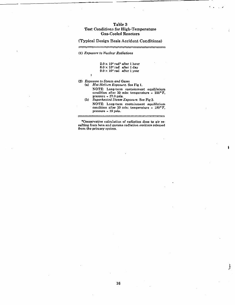
Table 3Test Conditions for High-Temperature
Gas-Cooled Reactors
(Typical Design Basis Accident Conditions)
(1) Exposure to Nuclear Radiations
2.0 x 10' rad* after 1 hour8.0 x 104 rad after I day9.0 x 10' rad after 1 year
(2) Exposure to Steam and Gases(a) Hot Helium Exposure. See Fig 1.
NOTE: Long-term containment equilibriumcondition after 30 min: temperature 2500°F,pressure = 37.0 psia.
(b) Superheated Steam Exposure. See Fig 2.NOTE: Long-term containment equilibriumcondition after 30 min: temperature 1900F,pressure = 19 psia.
'Conservative calculation of radiation dose to air re-sulting from beta and gamma radiation emitters releasedfrom the primary system.
16


![CENSUS OF INDIA - Linguistic Survey of Indialsi.gov.in:8081/jspui/bitstream/123456789/382/1/24475_1971_FP.pdfERRATA Paper] of 1972 - Final Population Table Page Col. No. No. Particulars](https://img.pdfslide.us/doc/110x75/6059609b0c7877142473e6f2/census-of-india-linguistic-survey-of-errata-paper-of-1972-final-population.jpg)