Embed Size (px)
Citation preview
IEEE JOURNAL OF SOLID-STATE CIRCUITS, VOL. 47, NO. 11, NOVEMBER 2012 2711
A 92-mW Real-Time Traffic Sign RecognitionSystem With Robust Illumination Adaptation and
Support Vector MachineJunyoung Park, StudentMember, IEEE, Joonsoo Kwon, StudentMember, IEEE, Jinwook Oh, StudentMember, IEEE,
Seungjin Lee, Member, IEEE, Joo-Young Kim, Member, IEEE, and Hoi-Jun Yoo, Fellow, IEEE
Abstract—A low-power real-time traffic sign recognition systemthat is robust under various illumination conditions is proposed.It is composed of a Retinex preprocessor and an SVM processor.The Retinex preprocessor performs the Multi-Scale Retinex(MSR) algorithm for robust light and dark adaptation underharsh illumination environments. In the Retinex preprocessor,the recursive Gaussian engine (RGE) and reflectance engine (RE)exploit parallelism of the MSR tasks with a two-stage pipeline,and a mixed-mode scale generator (SG) with adaptive neuro-fuzzyinference system (ANFIS) performs parameter optimizationsfor various scene conditions. The SVM processor performs theSVM algorithm for robust traffic sign classification. The proposedalgorithm-optimized small-sized kernel cache and memory con-troller reduce power consumption and memory redundancy by78% and 35%, respectively. The proposed system is implementedas two separated ICs in a 0.13- m CMOS process, and the twochips are connected using network-on-chip off-chip gateway. Thesystem achieves robust sign recognition operation with 90% signrecognition accuracy under harsh illumination conditions whileconsuming just 92 mW at 1.2 V.
Index Terms—Multiscale Retinex (MSR), network-on-chip(NoC), support vector machine (SVM), traffic sign recognition.
I. INTRODUCTION
O BJECT recognition has been highlighted as a key en-abler for various applications demanding visual intelli-
gence such as human friendly interfaces, intelligent robots, se-curity, and automotive vehicle systems [1]–[3]. Among these,the advanced driver assistance systems (ADAS) is receivingmuch attention since it can increase the level of safety as wellas give better experiences to the drivers in vehicle. Recently,many types of technologies have been investigated to support
Manuscript received February 11, 2012; revisedMay 05, 2012; accepted June21, 2012. Date of publication September 06, 2012; date of current version Oc-tober 26, 2012. This paper was approved by Guest Editors Shen-Iuan Liu andTsung-Hsien Lin. This work was supported by the Global Frontier R&D Pro-gram on “Human-centered Interaction for Coexistence” funded by the NationalResearch Foundation ofKorea grant funded by theKoreanGovernment (MEST)under Grant NRF-M1AXA003-2011-0028368.J. Park, J. Oh, S. Lee, and H.-J. Yoo are with the Department of Electrical
Engineering, Korea Advanced Institute of Science and Technology (KAIST),Daejeon 305-701, Korea (e-mail: [email protected]).J. Kwon is with the Memory Division, Samsung Electronics, Hwasung 445-
701, Korea.J.-Y. Kim is with Microsoft Research, Redmond, WA 98052 USA.Color versions of one or more of the figures in this paper are available online
at http://ieeexplore.ieee.org.Digital Object Identifier 10.1109/JSSC.2012.2211691
the functions for ADAS. Radar, magnetic referencing, high-ac-curacy digital maps with GPS, and vision-based techniques arethe key supporting techniques for ADAS, and the intelligentcars equipped with these techniques can support forward col-lision detection, front/rear park assist, and blind spot detection[4]. Among these, the vision-based driver assistance system isthe rapidly dominating technique because the video camera isan attractive device from the cost perspective, and it can operateconcurrently with radars, which has long ranging capability andazimuth accuracy, to increase accuracy as well as give additionalfunctionalities such as traffic sign recognition, object detection,and classification. However, the vision-based driver assistancesystem requires high computing power for image processingand pattern recognition, and it is difficult to realize the reliableand robust performance under harsh illumination conditions.In this paper, we propose a hardware architecture to achieve
robust performance under harsh illumination conditions by re-solving computationally expensive computer vision algorithmsin a low-power budget. Also, we will show the proposed archi-tecture can satisfy several requirements of the traffic sign recog-nition system for ADAS.Previous multicore object recognition processors [1]–[3]
were able to recognize the traffic signs by using limitedcomputing power. However, they are vulnerable to harshillumination conditions in driving environment such as abruptillumination changes in dark tunnels, specular reflections,smear effect, and backlight effect, as shown in Fig. 1. Bad illu-mination conditions should be taken into consideration in orderto make recognition processor show no performance degrada-tion compared with its operation in indoor environments.The performance of the previous system is degraded due to
the limited dynamic range of their image sensors in the casesof rapid changes of light intensity. Conventionally, the sensoryissues were addressed to resolve these problems, for example,reducing sensor noise or stabilization of conversion of electronsfrom photons [5]. Even though these approaches were effectiveto reduce the effect of sensor noise, there are still some problemssuch as the shifting of the intensity offset or limited dynamicrange.In order to realize the robust traffic sign recognition over-
coming the above problems, we adopt two different algorithms;Multiscale Retinex (MSR) at the front stage and support vectormachine (SVM) at the back stage of the recognition algorithmicpipeline. MSR is one of the image enhancement algorithms, andit shows good performance on dynamic range compression and
0018-9200/$31.00 © 2012 IEEE

2712 IEEE JOURNAL OF SOLID-STATE CIRCUITS, VOL. 47, NO. 11, NOVEMBER 2012
Fig. 1. Harsh illumination conditions in traffic sign recognition.
Fig. 2. Overall algorithm and hardware mapping.
color restoration [6]. It is basically based on the idea that humanbeing can easily see individual objects both in the sunlight and inshadowed area, since the eye locally adapts to the abrupt changeof light intensity. It improves the contrast, brightness, and per-ceived sharpness of the input images so that, in the next featureextraction stage of the recognition pipeline, more deterministicfeatures can be obtained for the better object recognition. TheSVM is well known for its classification accuracy [7] becauseit tries to maximize the margin of classification decision ratherthan to minimize the classification error in other classifiers whentraining. Even though the algorithms, MSR and SVM, have su-perior classification accuracy, they were rarely used in the mo-bile applications due to their demanding requirement of com-puting power.In this paper, the proposed system exploits two key features
to realize these algorithms for the reliable and robust real-timetraffic sign recognition under harsh illumination conditions.First, the Retinex preprocessor is designed to realize the MSRalgorithm with recursive Gaussian engine (RGE), reflectance
engine (RE), and a mixed-mode scale generator (SG) usingadaptive neuro-fuzzy inference system (ANFIS). Second, theSVM processor realizes the SVM algorithm with a supportvector kernel engine (SVKE) using an algorithm-optimizedkernel cache, and support vector search engine (SVSE) withproposed header combined database structure. The scalablenetwork-on-chip (NOC) interface is proposed to integrate thetwo chips on a single board by the off-chip gateway to realize30-frame rate of traffic sign recognition. It provides the commu-nication capacity with 640-MB/s maximum bandwidth and theNOC protocol also supports the connectivity with our previousplatforms [1]–[3] so that other platforms can optionally useSVM or MSR for their functional extension.The remainder of this paper is organized as follows. Section II
explains the overall system algorithm. Detailed architectures ofthe Retinex preprocessor and SVM processor are described inSections III and IV, respectively. Then, Section V describes thescalable NoC, implementation, and evaluation results of the pro-posed system. Finally, Section VI summarizes the paper.
PARK et al.: 92-MW REAL-TIME TRAFFIC SIGN RECOGNITION SYSTEM WITH ROBUST ILLUMINATION ADAPTATION AND SVM 2713
Fig. 3. (a) BDT-based SVM. (b) Performance comparisons of multiclass SVMs.
II. SYSTEM ARCHITECTURE
A. Overall Algorithm
In order to achieve reliable and robust traffic sign recognitioneven for the scenes under dynamically changing illuminationconditions, we present an integrated algorithm, which adoptsMSR and SVM. The sequence of algorithms explained aboveand their corresponding hardware are described in Fig. 2. Itconsists of three functional stages for the robust traffic signrecognition system: image enhancement, feature generation,and vector classification. In the first stage, it performs MSRalgorithm which includes three different Gaussian filtering andreflectance image calculation in the Retinex processor. Theselection of parameters, Gaussian filtering, and reflectance cal-culation are performed in separated accelerators, respectively.Through the inter-chip network connection, the enhanced
image from Retinex Processor is now processed in feature gen-eration and vector classification stages. The feature extractionis divided into 2 steps, which are outer extraction and innervector generation and they are processed in the acceleratorwhich is called Feature Extraction Engine (FFE). In the vectorclassification stage, Support Vector Kernel Engine (SVKE)and Support Vector Search Engine (SVSE) in the Recognitionprocessor accelerate SVM tree traversal to achieve the real-timeSVM operation. After the SVM operation, it finally achievesthe recognition result.Different from previous recognition processors [1]–[3], the
proposed system additionally includes the image enhancementstage, the MSR, for the first stage, to adapt harsh illuminationchanges. This stage generates the enhanced image as a resultwhich helps accurate feature extraction in the next stage. Themain idea of the MSR algorithm is that the reflectance or truecolor of object can be obtained by subtracting the illumination
from the perceived brightness, or lightness. The illuminationcan be deduced from the average value of surrounding pixels.As a result, the basic form of the Retinex algorithm is given by
(1)
(2)
where the subindex represents each channel of image and isthe total number of channels, for example, for a grayscaleimage and for typical color image. The representsthe surround function usually given as the Gaussian functionlike (2), which is used for calculating the illumination. andrepresent the input and output image, or called reflectance,
respectively.In this algorithm, it is critical to select the appropriate scale
parameter , which determines the extend amount of the sur-round for each scene. As gets smaller, the detail expressionof the image gets sharper, and, on the other hand, bigger re-sults in natural color rendition. The problem is how to find theappropriate scale parameter for the given scene:
(3)MSR, as shown in (3), uses three different kinds of the scale
parameters and sums up the corresponding images to achievea balance between dynamic range compression and tonal ren-dition whereas Retinex uses only one scale parameter. How-ever, the problem still remains because the values of three scaleparameters are still too sensitive to the scene variation. In this

2714 IEEE JOURNAL OF SOLID-STATE CIRCUITS, VOL. 47, NO. 11, NOVEMBER 2012
Fig. 4. Block diagram of the proposed traffic sign recognition system.
work, we use neuro-fuzzy inference algorithm with three typesof statistical data from image to estimate the optimal scale pa-rameters without any manual tuning. It is performed by themixed-mode Adaptive Neuro-Fuzzy Inference System (ANFIS)and will be explained later in Section III.After then, the feature extraction is performed in two steps
based on the MSR processed image: outer extraction and innervector generation. Because the traffic signs are designed for easyidentification using different symbols, colors and shapes, thecontour extraction stage generates the region-of-interest (ROI)for feature description based on these specific characteristicsby template matching. Then, the inner vector description usingscale-invariant feature transform (SIFT) [8] extracts some fea-tures from a local image region. In general, the traffic sign com-prises only a part of the entire image and the SIFT description isperformed in this small region. Therefore, in this work, it is pos-sible to perform the SIFT-based feature description in real-timewithout time overhead.Finally, the extracted vectors are classified by SVM. SVM
takes a set of input vectors, which are called as support vec-tors (SVs), so that the vectors of the separate classes can be di-vided by a maximum margin that is as wide as possible. SinceSVM is a binary classifier, multiple SVMs should be used to-gether in order to classify multicategories. A variety of tech-niques for classifying a multicategory classification problemusing binary classifiers have been proposed [9]–[11]. There arethree representative methods of forming multi-category clas-sifier using SVM: 1-vs-ALL, 1-vs-1, and binary decision tree(BDT). In 1-vs-ALL method, it constructs two-class SVM
classifiers for a -class problem. Each SVM is trained while la-beling the samples in one class as positive and the remainingsamples as negative. In the 1-vs-1 method, it constructs
two-class SVM classifiers for a -class problem. It use allthe binary pair-wise combinations of the classes, and eachSVM is trained while labeling the samples in one class as pos-itive and the sample in another class as negative. In the BDTmethod, it constructs a binary decision tree while each node ofthe tree is SVM which divides the samples into two categories.Among several multi-class implementations, the BDT-SVMhasrelatively low complexity as compared with 1-vs-1and 1-vs-all, which have the complexity of and ,respectively [11].In this work, the BDT-based SVM is adopted for multi
traffic sign recognition. Fig. 3(a) shows the algorithm flowof the adopted BDT-based multiclass SVM. By adopting theBDT-based SVM and optimized learning techniques, the clas-sification and learning time are 14 times faster and 15.4 timesfaster, respectively, than conventional learning algorithms asshown in Fig. 3(b).
B. Overall Architecture
Fig. 4 shows the overall block diagram of the proposedsystem, which performs the proposed traffic sign recognitionalgorithm combiningMSR and SVM. The Retinex preprocessorperforms MSR algorithm for illumination adaptation, and SVMprocessor performs SIFT-based feature extraction and SVMclassification. The Retinex consists of the recursive Gaussianengine (RGE), Reflectance Engine (RE), and a mixed-mode

PARK et al.: 92-MW REAL-TIME TRAFFIC SIGN RECOGNITION SYSTEM WITH ROBUST ILLUMINATION ADAPTATION AND SVM 2715
Fig. 5. Two-stage pipelined architecture for MSR implementation.
scale generator (SG) with ANFIS [12]. SG measures the sta-tistical data of the given image, which is down-sampled to80 60 and classifies it into one of the illumination levels byfuzzy inference. Then, SG determines the scale parameter ac-cording to the classified illumination level. The content-awareneuro-fuzzy inference in SG brings the better feature extrac-tion result by deciding the scale parameter of MSR algorithmautomatically.The MSR algorithm is organized into two stages, Gaussian
filtering and Reflectance acquisition, which will be explained indetail in Section III. RGE performs recursive Gaussian filteringwith low hardware overhead as the parameters of the Gaussianfilter are changing [13]. After Gaussian filtering, RE executesthe reflectance acquisition. The execution times of RGE andRE are adjusted equally by performing Gaussian filtering inthe recursive method and executing Reflectance acquisition inparalleled.The generated image after performing MSR algorithm is
transferred to the SVM processor for the feature extraction andrecognition of the traffic signs. The SVM processor consists ofthe feature extraction engine (FEE), the SVKE, and the SVSEas shown in the bottom of Fig. 4. The FEE extracts only thetraffic signs from the image and generating SIFT-based featurevectors. FEE again consists of two blocks: contour extractor(CE) and inner encoder (IE). The CE selects the region ofthe traffic sign while rejecting regions containing the otherdistractors. In the CE, the outer edge of a specific color, suchas red or blue, is traced and only ROIs of the traffic sign aresegmented in a tile-based approach [3]. The IE generates theSIFT-based feature descriptors of the segmented ROIs. After
Fig. 6. Processing time reduction by two-stage pipelined architecture.
the feature description is completed, the feature vector is clas-sified by SVKE, which performs SVM algorithm for featurevector classification. In order to implement SVM function tomeet the real-time requirement, a lookup-table (LUT) kernelcache is adopted in SVKE. SVSE controls the massive call ofthe support vectors from the SVKE with the 64-bit header and160-bit attributes, and logics.The Retinex preprocessor and SVM processor are im-
plemented in separate ICs and communicated through NoCoff-chip gateway on the board. The two proposed chips usethe same network interface on the off-chip gateway, whichhas been used in the previous object recognition chips [1]–[3].The 16-depth first-in–first-out (FIFO)-based synchronization
2716 IEEE JOURNAL OF SOLID-STATE CIRCUITS, VOL. 47, NO. 11, NOVEMBER 2012
Fig. 7. (a) Gaussian Engine in conventional and recursive method. (b) Required bit resolution. (c) Effectiveness of RGE features.
Fig. 8. Effects of the scale parameter on SIFT feature extraction.
switch is redesigned in the top switch for communicationstability and bandwidth requirement. The protocol interfaceof NoC is compatible to [1]–[3] so that the proposed pro-cessor can fully communicate with previous object recognitionchips for application extension. The details of two processors,Retinex preprocessor and SVM processor, will be explained inSection III.
III. RETINEX PREPROCESSOR
A. Two-Stage Pipelined MSR Algorithm
In this study, MSR is divided into two operation stages,Gaussian operation and reflectance. The former is performedby RGE and the latter is performed by RE in the Retinexpreprocessor. Gaussian operation can estimate the illumination

PARK et al.: 92-MW REAL-TIME TRAFFIC SIGN RECOGNITION SYSTEM WITH ROBUST ILLUMINATION ADAPTATION AND SVM 2717
Fig. 9. SG with ANFIS.
of the given image because common feature of the image likeillumination can be extracted by Gaussian filtering. Gaussianfiltering is performed in the recursive method [13] to achievethe pipelined operation. It is because in the recursive Gaussianmodel, the filtering operation at a pixel requires only 4 adjacentpixels in a row, that is, there is no data dependency betweenrows, so that it can be parallelized in row level.The Reflectance stage, as shown in Fig. 4, also has no data
dependency between pixels and can be parallelized in pixellevel. The Reflectance stage can be further divided into foursubstages as shown in Fig. 5. The four substages are composedof Logarithmic calculation, Restoration, Figure calculation, andRange rescaling. First, reflectance of the image is calculated bysubtracting the illumination information from the given image.Second, weights of three color channels (R, G, B) are decided.Third, figures of the image such as average, variance, max-imum, and minimum are calculated. Finally, the informationis used to rescale the resulting image for appropriate imageexpression.The number of processing elements in RGE and RE is de-
cided to balance their execution times to achieve the two-levelparallelism between Gaussian filtering and Reflectance. TheRGE has four processing elements for exploiting row levelparallelism of the recursive Gaussian method, and the RE hasten processing elements to use pixel level parallelism of the Re-flectance stage in MSR. The execution time of the Reflectancestage is further reduced by performing the color restoration andfigure calculation in parallel. Combining all of the features, theexecution time of RGE and RE can be overlapped and pipelinedby reducing its processing time by 73% in total. Fig. 6 showsthe processing time reduction according to the pipelining ofstages.
B. Recursive Gaussian Engine
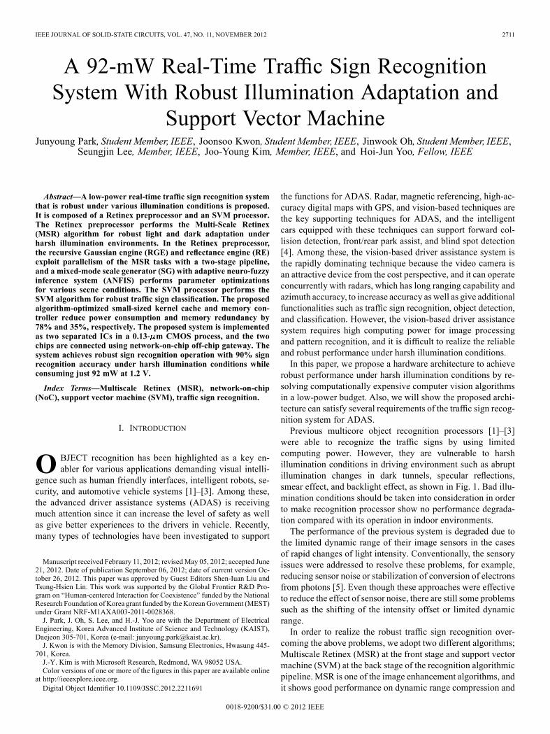
Fig. 7(a) compares the operations between the conventionalmethod and the recursive method [13]. In a conventional
Fig. 10. Feature extraction engine.
method, the radius of the Gaussian filter window is usually de-termined by three times the scale parameter of the filter in mostcases. Considering the fact that MSR algorithm requires severaldifferent types of scale values, different sizes of windows arerequired, or for example, more than 300 kinds of scale param-eters are required in QVGA-sized image. The undeterminedwindow size should be avoided in the pipelined operation be-cause the execution time is unexpected; furthermore, it requires
multiplications and additions for one pixel calcula-tion so that it is hard to manage the operation in a parallel way.On the other hand, the recursive Gaussian method decomposesGaussian operation into causal and anticausal filters, whichconsists of four multiplications along the adjacent pixel values.It dramatically reduces the required memory bandwidth for onepixel calculation because only four concurrent multiplicationsand additions are required. However, it has an error because itapproximates the coefficient values, not the exact values of thetrue Gaussian filter. In MSR, it is not a serious problem becausethe algorithm requires only three relatively different Gaussianfilters regardless of whether each filter has an accurate Gaussianfilter kernel. Even so, we use an adaptive bit-resolution control

2718 IEEE JOURNAL OF SOLID-STATE CIRCUITS, VOL. 47, NO. 11, NOVEMBER 2012
Fig. 11. (a) SVKE. (b) Two parameters of the kernel operation in SVM. (c) Effectiveness of SVKE features.
for better filter operation. Fig. 7(b) shows the required bit res-olution for maintaining the precision of the recursive Gaussianmethod, and it supports three different types of fixed pointoperation. In this work, 16-bit or 24-bit resolution operationis selectively used according to the scale parameters of theGaussian filter. With the adaptive resolution, we can reducethe power consumption by turning off the wide-bit processingelements if it is unnecessary. As shown in Fig. 7(c), total powerreduction amounts to 54% compared with the conventionalimplementation results estimated by the synthesis tools.
C. Mixed-Mode SG Using ANFIS
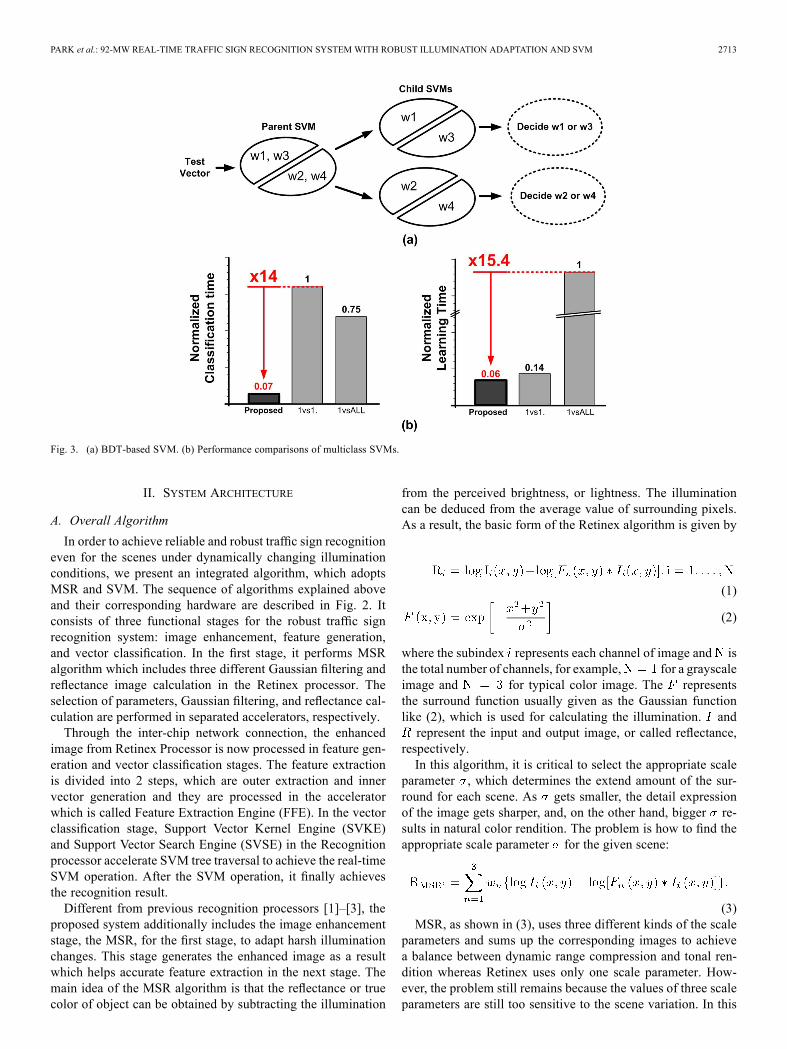
Fig. 8 shows that if the Retinex preprocessor chooses thewrong scale parameter for the Gaussian filter, it fails the featureextraction because of the resulted undesired clutters of MSR al-gorithm. Since the clutters are closely dependent on the pixel in-tensity variance of the image, the SG can be used to predict theoptimal scale parameter of the Gaussian filter using simple sta-tistics such as intensity variance, peak count, and average. Fig. 9shows the operation stages in SG which has neuro-fuzzy infer-ence steps and hardware mapping. The SG consists of a mixed-mode ANFIS [12] and a digital controller. By the mixed-modedesign, ANFIS takes advantages of low-power operation of thecurrent mode analog circuits resulting in reduce power reduc-tion by 15%.The mixed-mode ANFIS consists of five stages for neuro-
fuzzy inference: membership function calculation, fuzzy rule set
calculation, normalization, weight multiplication, and sum up.Among these steps, the analog datapath of themembership func-tion calculation is shown in Fig. 9, which performs nonlinearconversion of the input to fuzzy values. The boundaries of fuzzyvalues are controlled by and . The mixed-mode de-sign of ANFIS was first presented in [14] and has been usedfor its neuro-fuzzy inferences in several object recognition pro-cessors [3], [15]. In RGE, the circuit is revised to support mul-tidimensional operation with dimension controller. A detailedexplanation of the circuit operation can be found in [14]. Thedigital controllers in the other parts perform parameter loadingand NoC communication. The variance of the pixel intensitiesand the peak counts of a down-sampled image at each channelare loaded in the controller, and they provide the clues on the op-timal scale parameter for the given scene. In most cases, it is suf-ficient to predict only the scale parameter since the neuro-fuzzylogic finds the optimal scale values while performing learningoperation automatically.
IV. SVM PROCESSOR
A. Feature Extraction Engine (FEE)
Fig. 10 shows the detailed block diagram of the CE andIE, which have the finite-state-machine logic and partiallyprogrammable controller for their specific jobs – traffic signdetection and description – and several special processing ele-ments, which are border-to-distance calculation unit for traffic

PARK et al.: 92-MW REAL-TIME TRAFFIC SIGN RECOGNITION SYSTEM WITH ROBUST ILLUMINATION ADAPTATION AND SVM 2719
sign segmentation in CE and special ALU for SIFT-featuredescription in IE. Since the traffic sign has only specific colors,such as red and blue, and specific shapes in general, the CE usescolor information and distances from the border to a specificcolor outer rim of the traffic signs. The integrated 8-bit ALUin CE is capable of performing the segmentation in each colorchannel with the CE.After then, the segmented image results are stored in the
shared memory to provide them for IE. The IE performs thefeature description on the segmented part of the image. It hasa partially programmable controller with 4-kBytes instructionmemory, 16-bit extended ALU, and special ALU. In this work,scale-invariant feature transform (SIFT) is adopted because it isrobust to noise as well as invariant to scale and rotation [8]. Thecontroller supports some special instructions, such as parallelconvolution, for SIFT descriptor generation. The CE adopts8-bit ALU because it handles 8-bit resolution image, whereasthe IE adopts 16-bit ALU to meet the algorithm precisionrequirement of SIFT description. Special functions for SIFTdescription, such as SQRT, DIV, SIN/COS, and ARCTAN aresupported by the special ALU within three cycles.
B. Support Vector Kernel Engine
The generated feature vectors are then classified by SVMclassifier, which requires high computational cost due to itscomplex kernel operation. Fig. 11(a) shows the detailed archi-tecture of SVKE, which performs classification and learningoperations of SVM. In this study, we adopt the algorithm-op-timized one-dimensional kernel cache in SVKE to reduce thememory size requirement. It can store the pre-computed kerneloperation results to enable the complex kernel operation withsmall memory at one cycle while performing SVM’s classi-fication and learning functions. The key functions for SVMclassification and learning are shown, respectively, in
(4)
(5)
where is a coefficient, is a class value, is a featurevector, and denotes kernel operation. In both cases, thesefunctions should be repetitively performed as many times as thenumber of support vectors, which may be more than 1000 iter-ations in most cases. Usually, real-time performance is difficultbecause most of kernel operation have nonlinear functions re-quiring special floating-point hardware. Most of SVM kernel in-cludeGaussian radial basis function, or hyperbolic tangent func-tions [7]. An LUT can resolve the problem because it simplyloads the precomputed results. However, it requires relativelylarge memory for mobile system. For the kernel operation withtwo 8-bit resolution parameters, 64-kBytes memory is requiredfor LUT. For this reason, many studies have implemented thekernels in a limited linear function, 4-bit lower resolution, orlogarithmic number system [19]–[23]. However, as shown in (4)and (5), one of the kernel parameters is constant during the iter-ation. Fig. 11(b) shows the operations of the proposed scheme.
Fig. 12. SVSE.
The input parameters of kernel operation are the input vectorand support vectors. When performing the classification, theinput vector is constant while the kernel operation is repeatedfor processing all of the support vectors. Thus, the one-dimen-sional (1-D) kernel LUT cache fetches the kernel LUT resultscorresponding to one parameter before performing the kerneloperation. It reduces the memory requirements without perfor-mance degradation, comparing to the conventional case usingthe two-dimensional (2-D) LUT. Fig. 11(c) shows the effective-ness of the proposed 1-D kernel cache in comparison to the 2-Dkernel cache. Thanks to the reduced cache memory size, the av-erage accessing power consumption is reduced by 78% whilemaintaining the same throughput.
C. Support Vector Search Engine (SVSE)
Since SVM performs classification based on its support vec-tors and BDT based multiclass SVM has many common sup-port vectors between parent node and child nodes [9]–[11], itis critical that the common vectors are shared to reduce its re-quirement of large memory size. Fig. 12 shows the detailed ar-chitecture of SVSE and its support vector data format in accor-dance with its 160-bit datapath of processing elements. Eachsupport vector database consists of the header and attributes.The header part of the database format indicates which SVMhas these vector attributes as its own support vector. A binaryexpression is used, zero for no existence of support vector and

2720 IEEE JOURNAL OF SOLID-STATE CIRCUITS, VOL. 47, NO. 11, NOVEMBER 2012
Fig. 13. Top integration using NoC interface.
one for existence of support vector. The header part can in-dicate up to 64 SVMs. When the controller requests the ac-cess of support vector of a SVM, the header memory logic re-turns the corresponding vectors by Boolean operation. In SVM’slearning phase, the similarity check logic reduces the redun-dancy in memory of duplicated vectors by comparing the differ-ences of vector attributes. When the controller requests to storethe given vector as a support vector, the similarity check logicsearches the most similar vector in the database. If the differ-ence of the two vectors exceeds the threshold value, the givenvector is stored in the database as the new entry. Otherwise, thevector storage is replaced by updating of only the header part ofthe most similar vector. In the similarity check logic, the inputvector is connected directly to the sum of absolute differences(SAD) unit by a 160-bit datapath so that the vector comparisoncan be performed without overhead.As a result, it enables about 64 kByes of internal memory to
store more support vectors. In our applications for recognizing20 traffic signs, 54% of support vectors are duplicated.With thisscheme, the total memory requirement can be reduced by 35%.
V. SYSTEM IMPLEMENTATION
A. NoC Interface for Two-Chip Integration
In this study, a NoC is adopted as a communication methodrather than bus, because it provides sufficient bandwidth toeach channel and has good scalability by the router switch. Forinter-chip communication between Retinex preprocessor and
SVM processor, the FIFO-based synchronization switch with16-depth buffer is included in top switch for communicationstability. The NoC interface contains the configurable sourcerouting tables so that the entire routing path can be included inthe 38-bit header flit. The packet consists of three types: header,address, and data flits. It supports up to 15 burst operation and,finally, provides 640 MB/s of bandwidth in each direction.Considering that the required bandwidth for Retinex and SVMprocessors is about 55 MB/s at a QVGA-sized image, it fullysupports the full operation and is capable of processing up toVGA-sized image. In this work, we develop the system usinga QVGA-sized video interface.Fig. 13 shows the block diagram of NoC integration of two
chips. It uses a wormhole routing protocol that controls thepacket by smaller flow unit (flits) to reduce the input buffersize. The two chips are connected on the board in a hierar-chical star topology through the off-chip gateway path, as shownin Fig. 13. Because the previous object recognition processors[1]–[3] also have the same off-chip gateway path, it can com-municate without any modification.
B. Implementation Results
The proposed traffic sign recognition system is fabricated in a0.13- m CMOS technology. The Retinex preprocessor and theSVM processor are implemented in separate ICs and integratedtogether on an evaluation board through the same NoC protocol.All blocks are implemented by a standard-cell automatic Placeand Routing stage except the SG, which is custom-designed

PARK et al.: 92-MW REAL-TIME TRAFFIC SIGN RECOGNITION SYSTEM WITH ROBUST ILLUMINATION ADAPTATION AND SVM 2721
Fig. 14. System photograph and summary.
Fig. 15. Block diagram of the evaluation system.
with mixed-mode ANFIS. Fig. 14 shows the chip photographand summarizes its specifications. The Retinex preprocessoroccupies 2.1 1.7 mm consuming 42 mW at a 1.2-V powersupply and the SVM processor occupies 2.2 3.2 mm con-suming 50 mW at a 1.2-V power supply, respectively. The op-erating frequency of the processor is 200 MHz for IP blocks and400MHz for the NoC interface. The proposed system is capableof performing the traffic sign recognition at QVGA-sized imagein 30 fps real time.
C. System Evaluation
The proposed chips are evaluated in a test platform, shown inFig. 15, using QVGA-sized video that was recorded in a harshenvironment at night with irregular illumination of headlightfrom the front car. Video environment includes abrupt illumi-nation change, under-exposure, and backlighting. The Retinexpreprocessor and SVM processor are connected by the off-chipgateway interface in FPGA on the evaluation board. Full traffic
2722 IEEE JOURNAL OF SOLID-STATE CIRCUITS, VOL. 47, NO. 11, NOVEMBER 2012
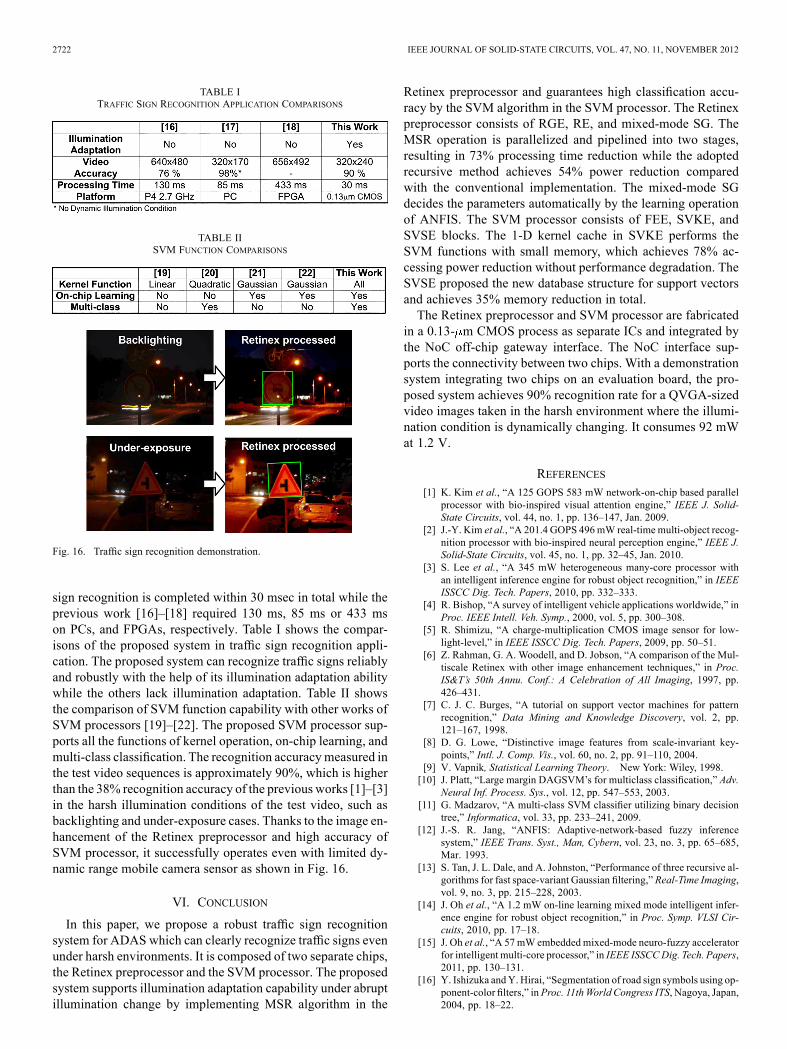
TABLE ITRAFFIC SIGN RECOGNITION APPLICATION COMPARISONS
TABLE IISVM FUNCTION COMPARISONS
Fig. 16. Traffic sign recognition demonstration.
sign recognition is completed within 30 msec in total while theprevious work [16]–[18] required 130 ms, 85 ms or 433 mson PCs, and FPGAs, respectively. Table I shows the compar-isons of the proposed system in traffic sign recognition appli-cation. The proposed system can recognize traffic signs reliablyand robustly with the help of its illumination adaptation abilitywhile the others lack illumination adaptation. Table II showsthe comparison of SVM function capability with other works ofSVM processors [19]–[22]. The proposed SVM processor sup-ports all the functions of kernel operation, on-chip learning, andmulti-class classification. The recognition accuracymeasured inthe test video sequences is approximately 90%, which is higherthan the 38% recognition accuracy of the previous works [1]–[3]in the harsh illumination conditions of the test video, such asbacklighting and under-exposure cases. Thanks to the image en-hancement of the Retinex preprocessor and high accuracy ofSVM processor, it successfully operates even with limited dy-namic range mobile camera sensor as shown in Fig. 16.
VI. CONCLUSION
In this paper, we propose a robust traffic sign recognitionsystem for ADAS which can clearly recognize traffic signs evenunder harsh environments. It is composed of two separate chips,the Retinex preprocessor and the SVM processor. The proposedsystem supports illumination adaptation capability under abruptillumination change by implementing MSR algorithm in the
Retinex preprocessor and guarantees high classification accu-racy by the SVM algorithm in the SVM processor. The Retinexpreprocessor consists of RGE, RE, and mixed-mode SG. TheMSR operation is parallelized and pipelined into two stages,resulting in 73% processing time reduction while the adoptedrecursive method achieves 54% power reduction comparedwith the conventional implementation. The mixed-mode SGdecides the parameters automatically by the learning operationof ANFIS. The SVM processor consists of FEE, SVKE, andSVSE blocks. The 1-D kernel cache in SVKE performs theSVM functions with small memory, which achieves 78% ac-cessing power reduction without performance degradation. TheSVSE proposed the new database structure for support vectorsand achieves 35% memory reduction in total.The Retinex preprocessor and SVM processor are fabricated
in a 0.13- m CMOS process as separate ICs and integrated bythe NoC off-chip gateway interface. The NoC interface sup-ports the connectivity between two chips. With a demonstrationsystem integrating two chips on an evaluation board, the pro-posed system achieves 90% recognition rate for a QVGA-sizedvideo images taken in the harsh environment where the illumi-nation condition is dynamically changing. It consumes 92 mWat 1.2 V.
REFERENCES[1] K. Kim et al., “A 125 GOPS 583 mW network-on-chip based parallel
processor with bio-inspired visual attention engine,” IEEE J. Solid-State Circuits, vol. 44, no. 1, pp. 136–147, Jan. 2009.
[2] J.-Y. Kim et al., “A 201.4 GOPS 496mW real-time multi-object recog-nition processor with bio-inspired neural perception engine,” IEEE J.Solid-State Circuits, vol. 45, no. 1, pp. 32–45, Jan. 2010.
[3] S. Lee et al., “A 345 mW heterogeneous many-core processor withan intelligent inference engine for robust object recognition,” in IEEEISSCC Dig. Tech. Papers, 2010, pp. 332–333.
[4] R. Bishop, “A survey of intelligent vehicle applications worldwide,” inProc. IEEE Intell. Veh. Symp., 2000, vol. 5, pp. 300–308.
[5] R. Shimizu, “A charge-multiplication CMOS image sensor for low-light-level,” in IEEE ISSCC Dig. Tech. Papers, 2009, pp. 50–51.
[6] Z. Rahman, G. A. Woodell, and D. Jobson, “A comparison of the Mul-tiscale Retinex with other image enhancement techniques,” in Proc.IS&T’s 50th Annu. Conf.: A Celebration of All Imaging, 1997, pp.426–431.
[7] C. J. C. Burges, “A tutorial on support vector machines for patternrecognition,” Data Mining and Knowledge Discovery, vol. 2, pp.121–167, 1998.
[8] D. G. Lowe, “Distinctive image features from scale-invariant key-points,” Intl. J. Comp. Vis., vol. 60, no. 2, pp. 91–110, 2004.
[9] V. Vapnik, Statistical Learning Theory. New York: Wiley, 1998.[10] J. Platt, “Large margin DAGSVM’s for multiclass classification,” Adv.
Neural Inf. Process. Sys., vol. 12, pp. 547–553, 2003.[11] G. Madzarov, “A multi-class SVM classifier utilizing binary decision
tree,” Informatica, vol. 33, pp. 233–241, 2009.[12] J.-S. R. Jang, “ANFIS: Adaptive-network-based fuzzy inference
system,” IEEE Trans. Syst., Man, Cybern, vol. 23, no. 3, pp. 65–685,Mar. 1993.
[13] S. Tan, J. L. Dale, and A. Johnston, “Performance of three recursive al-gorithms for fast space-variant Gaussian filtering,” Real-Time Imaging,vol. 9, no. 3, pp. 215–228, 2003.
[14] J. Oh et al., “A 1.2 mW on-line learning mixed mode intelligent infer-ence engine for robust object recognition,” in Proc. Symp. VLSI Cir-cuits, 2010, pp. 17–18.
[15] J. Oh et al., “A 57 mW embeddedmixed-mode neuro-fuzzy acceleratorfor intelligent multi-core processor,” in IEEE ISSCCDig. Tech. Papers,2011, pp. 130–131.
[16] Y. Ishizuka andY. Hirai, “Segmentation of road sign symbols using op-ponent-color filters,” inProc. 11thWorld Congress ITS, Nagoya, Japan,2004, pp. 18–22.

PARK et al.: 92-MW REAL-TIME TRAFFIC SIGN RECOGNITION SYSTEM WITH ROBUST ILLUMINATION ADAPTATION AND SVM 2723
[17] C. H. Lai and C. C. Yu, “An efficient real-time traffic sign recognitionsystem for intelligent vehicles with smart phones,” in Proc. Int. Conf.Technol. Applic. Artif. Intell., Nov. 18–20, 2010, pp. 195–202.
[18] M. Muller et al., “Design of an automotive traffic sign recognitionsystem targeting a multi-core SoC implementation,” in Proc. DATEConf. Exhib., 2010, pp. 532–537.
[19] G. Genov et al., “Kerneltron: Support vector machine in silicon,” IEEETrans. Neural Network, vol. 14, no. 5, pp. 1426–1434, Sep. 2003.
[20] S. Chakrabartty et al., “Sub-microwatt analog VLSI trainable patternclassifier,” IEEE J. Solid-State Circuits, vol. 42, no. 5, pp. 1169–1179,May 2007.
[21] S.–Y. Peng, B. A.Minch, and P. Hasler, “Analog VLSI implementationof support vector machine learning and classification,” in Proc. IEEEInt. Symp. Circuits Syst., 2008, pp. 860–863.
[22] K. Kang and T. Shibata, “An on-chip-trainable Gaussian-Kernel analogsupport vector machine,” in Proc. IEEE Int. Symp. Circuits Syst., 2009,pp. 2661–2664.
[23] F. M. Khan et al., “Hardware-based support vector machine classifica-tion in logarithmic number systems,” in Proc. IEEE Int. Symp. CircuitsSyst., 2005, pp. 5154–5157.
Junyoung Park (S’09) received the B.S. and M.S.degrees from the Korea Advanced Institute ofScience and Technology (KAIST), Daejeon, SouthKorea, in 2009 and 2011, respectively, where heis currently working the Ph.D. degree.His previous research interests include
low-power digital processors for vision appli-cations and a novel architecture for acceleratingvision algorithms on a system-on-chip. Recently,he has been investigating efficient implementationof heterogeneous system-on-chip architecture for
computer vision processing.
Joonsoo Kwon (S’09) received the B.S. and M.S.degrees from the Korea Advanced Institute ofScience and Technology (KAIST), Daejon, Korea,in 2009 and 2011, respectively. His M.S. workconcerned both low-power processor design andhuman-like image processing.He is currently with the Memory Division, Sam-
sung Electronics, where he is a Hardware Designerdeveloping flash memory for low-power and high-speed operation.
Jinwook Oh (S’08) received the B.S. degree fromSeoul National University, Seoul, Korea, in 2008,and the M.S. degree from Korea Advanced Instituteof Science and Technology (KAIST), Daejon, Korea,in 2010, where he is currently working toward thePh.D. degree, all in electrical engineering andcomputer science.His research interests include low-power digital
signal processors for computer vision. Recently, hehas been involved with the VLSI implementation ofneural networks and fuzzy logics.
Seungjin Lee (S’06–M’12) received the B.S., M.S.,and Ph.D. degrees from the Korea Advanced Insti-tute of Science and Technology (KAIST), Daejeon,Korea, in 2006, 2008 and 2011, respectively.He is currently a Researcher with the Department
of Electrical Engineering, Korea Advanced Instituteof Science and Technology (KAIST), Daejeon,Korea. His previous research interests includelow-power digital signal processors for digitalhearing aids and body-area communication andnovel architectures for accelerating neural networks
on a system-on-chip. Currently, he is investigating efficient heterogeneoussystem-on-chip architectures for computer vision processing.
Joo-Young Kim (S’05–M’12) received the B.S.,M.S., and Ph.D. degrees in electrical engineeringfrom the Korea Advanced Institute of Science andTechnology (KAIST), Daejeon, Korea, in 2005,2007, and 2010, respectively. His Ph.D. researchfocused on system-on-a-chip (SoC) architectures andcircuit innovations for low-energy object recognitionprocessing.In 2010, he joined Microsoft Research, Redmond,
WA, where he is currently a Research HardwareDesign Engineer engaged in the research and de-
velopment of client and cloud applications which target disruptive end-to-endconsumer experiences enabled by heavy use of innovative natural user inter-faces and cloud-backed services. More specifically, he is playing a key role ininventing customized architectures and circuits for computationally intensivecomputer vision algorithms such as camera tracking, dense 3-D reconstruction,motion recognition, and scene adaptation at power budgeted mobile devices.He has authored and coauthored over 35 journal publications and conferencepresentations in the area of solid-state circuits, including the IEEE InternationalSolid-State Circuits Conference, Symposium on VLSI Circuits, and the IEEEJOURNAL OF SOLID-STATE CIRCUITS. He has been invited to talk his researcheson computer vision and SoC validation at both industrial and research organi-zations such as Intel, nVidia, Texas Instruments and IMEC.Dr. Kim won two ISSCC presentations and two ISSCC/DAC design contests
from 2008 through 2010 for three parallel SoCs architected and designed byhim.
Hoi-Jun Yoo (M’95–SM’04–F’08) received theM.S. and Ph.D. degrees in electrical engineeringfrom the Korea Advanced Institute of Science andTechnology (KAIST), Daejeon, Korea.He was the VCSEL pioneer in Bell Communi-
cations Research, Red Bank, NJ, and Manager ofthe DRAM Design Group, Hyundai Electronics,designing from 1 M DRAM to 256 M SDRAM.Currently, he is a full professor of Department of
Electrical Engineering at KAIST and the director ofthe System Design Innovation and Application Re-
search Center (SDIA). From 2003 to 2005, he served as the full time Advisorto the Minister of Korean Ministry of Information and Communication for SoCand Next Generation Computing. His current research interests are Bio InspiredIC Design, Network on a Chip, Multimedia SoC design, Wearable HealthcareSystems, and high speed and low power memory. He has published more than250 papers, and wrote or edited 5 books, “DRAM Design” (1997, Hongneung),“High Performance DRAM” (1999 Hongneung), “Low Power NoC for HighPerformance SoC Design” (2008, CRC), “Mobile 3-D Graphics SoC” (2010,Wiley), and “BioMedical CMOS ICs” (Co-editing with Chris Van Hoof, 2010,Springer), and many chapters of books.Dr. Yoo received the Korean National Medal for his contribution to Korean
DRAM Industry in 2011, the Electronic Industrial Association of Korea Awardfor his contribution to DRAM technology the 1994, Hynix Development Awardin 1995, the Korea Semiconductor Industry Association Award in 2002, BestResearch of KAIST Award in 2007, Design Award of 2001 ASP-DAC, Out-standing Design Awards of 2005, 2006, 2007, 2010, 2011 A-SSCC, and KoreanScientist of the Month Award (Dec. 2010). He is a member of the executivecommittee of Symposium on VLSI, and A-SSCC. He was the TPC chair of theA-SSCC 2008, a guest editor of IEEE JSSC and IEEE T-BioCAS. He was theTPC Chair of ISWC (International Symposium on Wearable Computer) 2010,IEEE Fellow, IEEE Distinguished Lecturer (’10–’11), Far East Chair of ISSCC(’10–’11), and currently ISSCCTechnologyDirection Sub-committee Chair andan associate editor of IEEE TCAS-II.


![Illumination-Aware Age Progressionnovel illumination-aware age progression technique, lever-aging illumination modeling results [1,31], that properly account for scene illumination](https://img.pdfslide.us/doc/110x75/5e72745a0ac7de5cbf4199be/illumination-aware-age-progression-novel-illumination-aware-age-progression-technique.jpg)