Embed Size (px)
Citation preview
1
omniran-16-0038-00-CF00
SDN Functional DecompositionDate: 2016-06-20
Authors:Name Affiliation Phone Email
Antonio de la Oliva UC3M +34657079687 [email protected]
Notice:This document does not represent the agreed view of the OmniRAN TG It represents only the views of the participants listed in the ‘Authors:’ field above. It is offered as a basis for discussion. It is not binding on the contributor, who reserve the right to add, amend or withdraw material contained herein.
Copyright policy:The contributor is familiar with the IEEE-SA Copyright Policy <http://standards.ieee.org/IPR/copyrightpolicy.html>.
Patent policy:The contributor is familiar with the IEEE-SA Patent Policy and Procedures:<http://standards.ieee.org/guides/bylaws/sect6-7.html#6> and <http://standards.ieee.org/guides/opman/sect6.html#6.3>.
AbstractThis document proposes initial draft text for the SDN chapter of IEEE 802.1cf

2
omniran-16-0038-00-CF00
1 SDN Functional Decomposition.............................................................................................31.1 Definitions......................................................................................................................................31.2 Introduction...................................................................................................................................3
1.2.1 Generic SDN Architecture.......................................................................................................31.2.2 Open Network Foundation: OpenFlow....................................................................................41.2.3 SDN for Radio Access Networks.............................................................................................6
1.3 Acronyms.......................................................................................................................................71.4 Roles and identifiers......................................................................................................................71.5 NETCONF protocol and YANG modelling................................................................................71.6 Use Cases........................................................................................................................................9
1.6.1 Setup of interfaces and nodes...................................................................................................91.6.2 Detection of terminal attachment.............................................................................................91.6.3 Data Path Establishment........................................................................................................101.6.4 Data Path Maintenance..........................................................................................................111.6.5 Data Path relocation...............................................................................................................111.6.6 Data Path Teardown...............................................................................................................111.6.7 Control Path Maintenance......................................................................................................121.6.8 Affecting the behavior of Coordination and Information System.........................................121.6.9 Configuration of connection between the Access Router and the Access Network..............121.6.10 Event Handling......................................................................................................................121.6.11 Statistic gathering...................................................................................................................131.6.12 Triggering technology specific functionality from the controller..........................................13
1.7 SDN specific attributes................................................................................................................131.7.1 Terminal Configuration..........................................................................................................131.7.2 Access Network Configuration..............................................................................................141.7.3 Data path Establishment.........................................................................................................141.7.4 Triggering technology specific features.................................................................................141.7.5 Interacting with CIS...............................................................................................................14
1.8 Detailed procedures.....................................................................................................................141.8.1 Simple Switch logic...............................................................................................................151.8.2 Wireless LAN controller based on SDN................................................................................16
3
omniran-16-0038-00-CF00
1 SDN Functional Decomposition
1.1 DefinitionsFlow: Succession of packets which share a common addressing parameters and are forwarded according to a common behavior.
Path: Succession of dataplane elements which a flow transverse in their way between a source and destination.
1.2 IntroductionOver the last few years, the Software Defined Networking (SDN) paradigm has gained a lot of popularity. SDN decouples the system that makes decisions about where traffic is sent (i.e., control plane) from the underlying system that forwards traffic to the selected destination (i.e., data plane). With SDN, network administrators can program the behaviour of the network in a centralised way, without requiring to access and configure each of the hardware devices independently, which greatly simplifies overall network management.
It is important to highlight that SDN is merely a tool that enables innovation in network control. SDN neither dictates how that control should be designed nor solves any particular problem, this means that the actual protocol or control state machine is left for the application developer to design and implement, leaving the door open to innovation and differentiation in the market.
SDN has two defining characteristics: SDN separates the control plane (which decides how to handle the traffic) from the data
plane (which forwards traffic according to decisions that the control plane makes). SDN consolidates the control plane, so that a single software control program controls
multiple data-plane elements. The SDN control plane exercises direct control over the state in the network’s data-plane elements (i.e., routers, switches, and other middleboxes) via a well-defined Application Programming Interface (API).
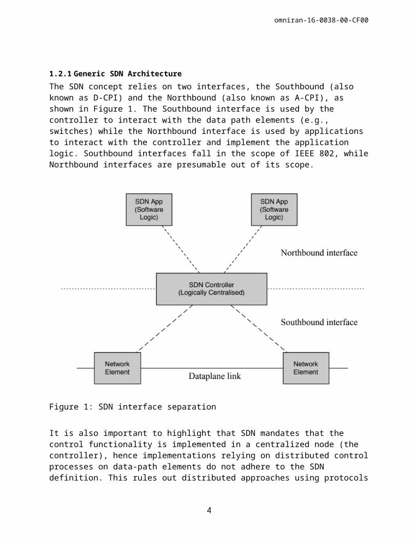
1.2.1 Generic SDN ArchitectureThe SDN concept relies on two interfaces, the Southbound (also known as D-CPI) and the Northbound (also known as A-CPI), as shown in Figure 1. The Southbound interface is used by the controller to interact with the data path elements (e.g., switches) while the Northbound interface is used by applications to interact with the controller and implement the application logic. Southbound interfaces fall in the scope of IEEE 802, while Northbound interfaces are presumable out of its scope.
4
omniran-16-0038-00-CF00
Figure 1: SDN interface separation
It is also important to highlight that SDN mandates that the control functionality is implemented in a centralized node (the controller), hence implementations relying on distributed control processes on data-path elements do not adhere to the SDN definition. This rules out distributed approaches using protocols such as SPB and/or MMRP protocols which work by exchanging information between data path elements and reaching a consensus state in the network, without the intervention of a central controller taking the decisions.
Note that Southbound protocols are used to interact with the dataplane elements. There may be different purposes for this interaction, requiring different protocols. Well known controllers such as ONOS or OpenDaylight implement several different Southbound protocols. The protocol of choice typically used for the control of the packet forwarding is the ONF OpenFlow. For network configuration there are several protocol which may be used such as OF-Config, SNMP, NETCONF, etc. Some of them are already used within IEEE 802 networks, such as SNMP.
1.2.2 Open Network Foundation: OpenFlowAmong the different protocols that can be used to realise the SDN concept, OpenFlow [REF] is the one most widely adopted by the telecommunications industry. OpenFlow design is based on 5 characteristics (known as the 5C):
Plane separation
5
omniran-16-0038-00-CF00
o Forwarding functionality, including the logic and tables for choosing how to deal with incoming packets based on characteristics such as MAC address, IP address, and VLAN ID, resides in the forwarding plane.
o The protocols, logic, and algorithms that are used to program the forwarding plane reside in the control plane.
Simplified deviceso Not implementing complex control plane protocols and operations.
Centralised Controlo Instead of hundreds of thousands of lines of complicated control plane software
running on the device and allowing the device to behave autonomously, that software is removed from the device and placed in a centralized controller.
Network automation and virtualizationo SDN can be derived precisely from the abstractions of distributed state,
forwarding, and configuration o They are derived from decomposing into simplifying abstractions the actual
complex problem of network control faced by networks today. Openness
o SDN interfaces should remain standard, well documented, and not proprietary. o The premise is that keeping open both the northbound and southbound interfaces
to the SDN controller will allow for research into new and innovative methods of network operation.
OpenFlow is used to configure the behavior of a flow within a switch. A flow in OpenFlow is defined as a set of packets, but the OpenFlow protocol is completely stateless with regards to flow characteristics. All operations of OpenFlow are based on Flow Entries which are stored in Flow Tables (one or several) within the OpenFlow Switch. A Flow Entry is composed of several elements. The most relevant to current discussion are the Match Fields and the Instructions. Basically a Flow Entry defines the packets it must be applied to by the Match Fields. OpenFlow defines different Match Fields in a very flexible way, examples of such matches may be source/destination MAC address, IP addresses, transport protocol, ports, etc.. Once a packet matches a certain Match Entry then the Instruction contained in the Flow Entry is applied. Instructions contain the treatment that the switch must applied to the packet. A packet may be modified, enqueued, meatered or just forwarded to a certain port. An special case of this behavior occurs when a packet is forwarded to the SDN controller, due to a special instruction in a Flow Entry or the lack of Flow Entry matching the packet (Table Miss Entry).
As mentioned before, one possible Instruction in OpenFlow is to enqueue a packet. It is important to understand that currently OpenFlow does not support the creation or configuration of queues. In fact, currently the administrator of the switch requires to create the queue, configure it and attach it to the switch port. After that, the OpenFlow switch can make use of it. The same is required for the use of meters (one kind of shapers defined in OpenFlow).
To finalise this section, it is worth highlighting the configuration support that OpenFlow provides. OpenFlow currently supports configuration primitives for two port classes; Ethernet and Optical ports. An Optical port is an extension of an Ethernet port with some extra configuration parameters such as the wavelength to use or the power of the laser. The
6
omniran-16-0038-00-CF00
configuration of any other parameter is currently not possible with OpenFlow. In this cases, the controller will rely on any other Southbound protocol, such as SNMP, to configure the Optical properties of the port.
1.2.3 SDN for Radio Access Networks
While so far SDN efforts have been mostly focused on wired networks, and comparatively little attention has been paid to applying it to wireless, the potential benefits of this technology extended to adequately support mobile networks are much higher than with wired networks, for the following reasons:
It allows to manage all the heterogeneous technologies (such as cellular or WLAN) in a transparent way, hiding the specificities of the technologies to the TE tool.
It allows to integrate in a single decision point different types of communication that have traditionally been handled separately, such as device-to-device and infrastructure communications.
It can also be used to address new functions that are not needed in wired networks, such as switching off those points of access that are not needed at a given point in time, and thus reduce energy consumption.
Finally, using an adequate abstraction of wireless resources, handling the complex capacity calculations in heterogeneous deployments could be as simple as in wired networks
Within the IEEE 802 set of technologies, there are multiple functionalities which can be designed based on the SDN paradigm. This document presents several use cases showcasing these functionalities:
Setup of interfaces and nodes
Detection of node attachment
Path Establishment
Path Tear Down
Path Maintenance
Path relocation
Affecting the behavior of Coordination and Information System
Configuration of connection between the Access Router and the Access Network
Event handling
Statistic gathering
Another important point raised within the SDN community has been the need of a common and extensible protocol allowing the configuration of devices in a centralized way. One of the major problems faced now in the management of large networks is the lack of a secure protocol enabling the common configuration of all devices in the network. One may argue that the use of MIBs and the SNMP protocol solves this issue but in reality the use of this protocol is not

7
omniran-16-0038-00-CF00
exempt of problems. In addition, the MIBs are difficult to maintain and their definition lacks of clarity, and the administrators of large networks usually have to use vendor locked tools and specific scripts to configure their networks. The networking community is looking at other recent tools to overcome these issues being the champion of this approach the NETCONF protocol, that uses YANG models as data representation tool. This document also presents an overview of this protocol and data representation model.
1.3 AcronymsCIS Coordination and Information System
CN Access Router
AN Access Network
1.4 Roles and identifiers Controller: Application that manages different behaviors (e.g., flow control) in a Software
Defined Networking environment.
Data path element: Hardware/Software entity in charge of executing the orders from the controller, affecting the path through which data is forwarded.
1.5 NETCONF protocol and YANG modellingAs explained in the introduction, managing a communication network is a costly and difficult operation that currently is not performed in a programmatic way:
A huge number of human resources are employed on maintaining network configuration, performance and security.
Configuration errors are the main cause of network failures. Usually these errors came from erroneous human intervention and they cost millions in downtime and recovery.
Current techniques are based on custom, locked-in CLI procedures, error prone.
There is a clear need for a programmatic mechanism for the management of configuration data and standard mechanisms for the management of heterogeneous, multiple-vendors network equipment. This is the hole that NETCONF tries to fill in.
NETCONF is a new transaction-based protocol for programmatic management of network configurations which builds on top of well-known protocols (SSH, XML, SOAP) to provide secure configuration of heterogeneous devices.
The key characteristics of the NETCONF protocol are listed in the following:
It supports partial device configuration to the most fine-grain level.
It supports full device configuration with a single operation and network wide device configuration.
It supports reporting error codes for partially or completely failed configuration requests.
8
omniran-16-0038-00-CF00
It supports sending configuration requests independent of the completion of previous requests. Requests may be queued or processed concurrently at a device. Each request has a request ID. Success or failure indications can be sent independently of other requests individually for each request ID.
It is extensible. New operations can be added and its support can be checked by capability retrieval.
Configurations of a device or for portions of it are encoded in XML
UML XML Schema is also provided
For each of the elements the specification provides UML class description and XML example
One of the key points on any management protocol is the security. In order to assure correct security for its operations, NETCONF supports SSH (RFC6242) and TLS (RFC5539) as communication transport protocols that can be used for providing integrity, privacy, and mutual authentication. All specified transport mappings for NETCONF use TLS or TCP as underlying transport protocol and thus provide reliable transport.
A data model is a consistent and complete definition of the structure, syntax and semantics of data. NETCONF uses YANG data modeling language to model both configuration data as well as state data of network elements.
YANG is a modular language representing data structures in an XML tree format, making it very appropriate for the definition of the NETCONF structures. The data modeling language comes with a number of builtin data types, from which additional data types can be derived if needed. A YANG module defines a hierarchy of data that can be used for NETCONF-based operations, including configuration, state data, Remote Procedure Calls (RPCs), and notifications. This allows a complete description of all data sent between a NETCONF client and server. The hierarchy of data is organized as a tree, in which each node has a name and either a value or a set of children. The language defines the nodes and their interaction.
The YANG data model is structured in modules, which can be formed by submodules. Any module can import data from external modules and even modify the hierarchy defined in other module by adding nodes to that module. This can be done conditionally only if certain conditions are met. In addition, through YANG, constraints can be enforced on the data, restricting the value of appearance of nodes based on the presence or value of other nodes.
To the extent possible, YANG maintains compatibility with Simple Network Management Protocol's (SNMP's) SMIv2 (Structure of Management Information version 2 [RFC2578], [RFC2579]). SMIv2-based MIB modules can be automatically translated into YANG modules for read-only access. However, YANG is not concerned with reverse translation from YANG to SMIv2.
To finalize this clause, it is worth noting that some Task Groups in the IEEE 802 are already working towards the definition of YANG models for the management of the configuration of some technologies. One example of this is the IEEE 802.1Qcp, defining the YANG model for bridges and bridged networks.

9
omniran-16-0038-00-CF00
1.6 Use CasesPlease note that although the above descriptions are clearly focused on NETCONF, we argue that this protocol is useful for some purposes but it is clearly not the best one for every single use case and there is space for other choices. It is not in the scope of IEEE 802.1cf to define such protocols.
1.6.1 Setup of interfaces and nodesThrough SDN a central controller can implement a control logic enabling it to configure several parameters in the nodes and interfaces of the data path. These parameters may change at different timescales, requiring protocols and configuration loops according to their timescales.
SDN control configuration refers to the required setup of the parameters ruling the communication between the data path element and the controller. These parameters may include IP address of the controller, kind of protocol, VLAN or interface used for the communication and certain timers governing the transmission of keep alive messages or the tear down of it in case of failure. These configuration parameters must also include the different timers, ports and protocols used for the communication between the controller and the data path element.
Short time scale configurations are related with the configuration of parameters, which may change in very short time scales. For example, transmission power, MAC QoS parameters, antenna selection, etc.
Long time scale configuration refers to the long-term configuration of the node or interface; the parameters used by the controller are the typical ones an OAM system may use. Examples of these parameters include the operational frequency, configuration regarding credentials or authentication servers to use, supported authentication modes, VLAN configuration, etc.
While considering what parameters can be configured by a central controller, one may think of all the current parameters defined in MIBs for IEEE 802 technologies.
A typical example of SDN based configuration can be taken from the world of IEEE 802.11 where WLAN controllers configure the different parameters of the technology. The typical parameters that the controller will setup are operational frequency and transmission power. Depending on the technology the controller will also be able to configure additional parameters such as RTS threshold or ESSID/BSSIDs of the different APs. The actual configuration to be installed may come from different sources ranging from fully automatic algorithms computing the best allocation of e.g., frequency/transmission power to static allocations.
1.6.2 Detection of terminal attachmentA very important operation required to use SDN control in the access network is the possibility of detecting the attachment of new terminals. The user’s terminal, typically will not include any kind of SDN software nor they are aware of connecting to a network using an SDN controller. In this way, it is needed some mechanism to handle the detection of the terminals while attaching to the network PoAs. In a PoA where the wireless interface (IEEE 802.11) is bridged to a switch, this detection of terminal attachment can be done thanks to the switch sending a LLC SNAP
1
omniran-16-0038-00-CF00
message upon attachment of a new terminal. In other technologies some other mechanisms should be analysed.For the IEEE 802 technologies is quite important to define mechanisms able to provide a central controller with information on the user attachment. Simple mechanisms as the one presented for IEEE 802.11 (bridged to a switch) are not compatible with more complex technologies involving exchanges with the AAA service of the network. In addition, technologies such as IEEE 802.16 rely on complex protocols and interactions with the core to manage the user association. A clear view on how to detect user attachments per technology should be consider in order to apply the SDN concept to a complete network.
1.6.3 Data Path EstablishmentAn IEEE 802.1cf network does not include IP layer, hence path establishment mechanisms using above layer-2 information are out of the scope of this document. In order to establish a path, a controller requires to be informed of the new flow, including its requirements in terms of capacity, delay and jitter. After receiving this information the controller can compute the best possible path and communicate this decision to the data path elements. After this, the data path elements will enforce the controller decision on the different packets traversing the data path.
For this specific clause, it is important to distinguish between the concept of SDN and the actual implementation of this concept, such as OpenFlow. While SDN is basically the concept of control/data plane split and centralized control applied to a network, OpenFlow realizes these ideas on IEEE 802.1 compliant switches. It is very important for IEEE 802 readers, to understand the differences between the technologies and how the SDN idea can be implemented on them. As an example: while a network composed completely out of switches can be discoverable by an OpenFlow controller, a network in which these switches are connected also to a wireless network composed of several nodes, cannot. This is due to the differences between the IEEE 802.1 switch and an IEEE 802.11 portal. In this case anything below the portal will be invisible to the OpenFlow controller (although IEEE 802.11ak work will solve some of these issues).
For the general case, in order to perform the data path establishment, the following information/functionality is required:
Topology information Mechanisms to compute best path based on some criteria A mechanism in the IEEE 802 device able to apply a per-flow/per-packet policy. This
policy will be named rule in the following. Communication mechanisms to set specific rules in the data path to decide output
port/modifications to frame The data path must support some mechanism for packet matching. This mechanism can
be arbitrarily complex. It can include simple mechanisms as input port matching, VLAN tag matching or complex rules indicating logical combination of parameters, including internal state of the data path element.
The data path must support the application of forwarding rules to the input traffic. In this way the decisions taken by the controller will be applied and the packet will be sent through the appropriate output port.
The data path element may support actions over the packets and internal state. The data

1
omniran-16-0038-00-CF00
path element may be able to modify certain parts of the packet and modify internal state variables, such as counters, monitoring variables, etc..
Also consider that in some of the technologies considered, a packet may not be accessible. For example, an optical link performing optical passthrough. In this cases, the data path setup will consist on the configuration of the parameters defining how the flow is managed, not in a specific packet per packet basis.There are multiple considerations when dealing with data path establishment; depending on the technology of choice (e.g., OpenFlow, MVRP, SNMP, etc.) the data path will be installed based on static rules such as port allocated VLANs or it will be installed based on intelligent packet matching rules. As result of this operation each data path element should have a rule stating the forwarding behavior for packets belonging to a certain flow. The computation of the path to be installed depends on the technology of choice for the controller, since there are technologies computing a path in a distributed way and technologies that can run traffic engineering+policying algorithms.In addition to the pro-active instantiation of a path described in the above text, a data path element may reactively interact with the controller due to some event, new packet arrival or pre-installed rule among others. Following this, the data path element may interact with the controller in order to build a path for a specific new flow that has just appeared and for any reason should not be forwarded through the pre-configured paths.
1.6.4 Data Path MaintenanceTypically a data path element will configure forwarding rules with a certain lifetime. The rules must be updated within their lifetime, or the data path element will remove them. Upon expiration of the rule, the data path element should inform the controller about the removal of the rule. In this way, the controller can keep record of the current status of the paths in the network.
1.6.5 Data Path relocationDue to several reasons such as traffic engineering, movement of the terminal or QoS degradation, it may be necessary to relocate a data path. With relocation we meant to change the data path elements the data path goes through, while keeping the most similar allocation of resources. This functionality can be divided in a sequence of Data Path establishment and Data Path Tear Down.
1.6.6 Data Path TeardownA certain path can be created for a specific flow. Once the flow finishes, there is no need to have the path established any longer, freeing resources allocated to the path. In order the controller to tear down a path, it needs to discover that the path can be deactivated. This can be done through monitoring metrics or flow information coming from the flow originator. Once the controller knows that the path can be removed, it can communicate the data path elements its decision. At this moment all data path elements will remove the stored state corresponding to this path. This implies the IEEE 802 device must be able to obtain performance statistics and reporting them to the central controller.

1
omniran-16-0038-00-CF00
1.6.7 Control Path MaintenanceIn the same way as with data paths, the communication between the controller and the different data path elements must be kept alive through the exchange of some control packets.
1.6.8 Affecting the behavior of Coordination and Information SystemTerminals and network nodes can rely on Coordination and Information Services (CIS) to gather information helping them to take some decision, such as candidate network selection, channel to use, etc. A controller may interact with the CIS in a standalone way or it may mediate in the communication between the terminal and the CIS. This later approach allows the controller to modify, apply policies, add more information or simply query different servers based on terminal information such as its user profile.The AN controller is able to communicate with the CIS system in order to add/remove/modify its information based on its knowledge about the network. One example would be to update the list of services being advertised in IEEE 802.11aq based on information obtained from the network. In addition to this, a controlled network can be configured in such a way that the controller is used as proxy for the CIS communication. In this way the controller will get the answer from the CIS and can modify it accordingly to get some expected behavior in the network. For example, a controller may be used as proxy to access an IEEE 802.21 Media Independent Information Service (MIIS) and after receiving the response filter it in order to remove the surrounding networks that do not belong to a specific operator, in this way enforcing some policy in the terminal.
1.6.9 Configuration of connection between the Access Router and the Access NetworkAn IEEE 802 access network is connected to an Access Router through a network known as backhaul. Typically, the backhaul network is composed of IEEE 802 switches or MPLS/IP routers. For the scope of this specification we will focus on the former. In addition, there is a currently a trend pushing for a separation between the radio part of the access network (implementing only some parts of the physical/MAC layers) and the processing of the signal or remaining stacks of the protocol layer in a separated way. The network connecting both elements is known as the fronthaul and has some specific and highly constrained requirements, such as high bandwidth and extremely low latency. Examples of this network in the IEEE ecosystem is the work performed in IEEE 802.1CM. All approaches rely on IEEE 802.1 switches to perform the actual forwarding of the data. Considering both transport networks (the backhaul and fronthaul), these networks must carry the user packets to the point of connection to the Access Router. Multiple Access Routers may connect to the Access Network in several points, and the Access Network (or even the transport) can be shared among multiple tenants. For this specific case, the traffic must consider to build the paths towards the destination, not only what is the most appropriate point of connection to the IP service, but also what isolation mechanism to be used to transfer each tenant traffic. Hence mechanisms for establishing Bridging (IEEE 802.1Q), Provider Bridging (IEEE 802.1ad) or Provider Backbone Bridging (802.1ah) paths through the network and automatic configuration of the end points is needed.
1.6.10 Event HandlingCurrent SDN southbound protocols provide mechanisms for Event Handling. As an example,

1
omniran-16-0038-00-CF00
OpenFlow is working on the definition of Alarms and it already includes mechanisms to notify of the change in the status of ports, among other things. The current problem of these approaches is their limitations, since they do not consider the multiple and different characteristics of the IEEE 802 technologies. In this way, for example, there is no concept of wireless port, hence none of the wireless specific characteristics, such as e.g., number of retransmissions crossing a certain level, can be rolled back to the controller. Mechanisms such as the Event Service of IEEE 802.21 may be used to solve this problem, although a common way to report this events and the definition of the data models related should be considered by the IEEE 802.
1.6.11 Statistic gatheringIn the same way as with the Event Handling in clause 1.5.10, SDN southbound protocols implement mechanisms for Statistics gathering, which can be used to alter the way flows are treated within the network. Regarding IEEE 802 technologies, this faces the same problem as Event Handling, since the statistics defined are mostly based on packet counting and do not consider the specific characteristics of IEEE 802 technologies.
1.6.12 Triggering technology specific functionality from the controllerAlthough SDN controllers have been used typically to setup data paths in the network and configure characteristics of the interface, the complete possibilities of controlling the specific features of the technologies have not been analyzed. The use of technology specific features by a controller can yield to further advantages for the network. For example, a controller may configure the QoS across a mix of wireless and wired domains, by triggering the QoS configuration mechanisms of each technology. Another example may use management frames of IEEE 802.11v to control the point of attachment of the user terminal. To open all this functionality the controller needs of a clear view of the capabilities of the interface and new APIs to trigger it in a remote way.
1.7 SDN specific attributesThis section lists possible parameters for the different functions involved in the SDN operation. We have explicitly removed the parameters that are already available in the MIB, since these parameters can already be accessible by a controller.
1.7.1 Terminal Configuration Terminal Controller:
o LIST of control capabilitieso LIST of interfaces and their capabilitieso LIST of protocols to manage interfaces
E.g., interface X supports CAPWAP+OF Interface
o Abstract parameterso LIST of parameters to be configured
Technology specific: e.g., BSSID to connect to, RTS Threshold, Short retry, long retry, fragmentation threshold, Tx/Rx MSDU lifetime, enable

1
omniran-16-0038-00-CF00
Block Ack, etc. Security parameters (technology dependent)
1.7.2 Access Network Configuration Configuration of interfaces
o Abstract parameterso LIST of parameters to be configured
Technology specific: e.g., BSSID, RTS Threshold, Short retry, long retry, fragmentation threshold, Tx/Rx MSDU lifetime, enable Block Ack, etc.
Technology specific security parameters: WPA/WPA2/WEP, parameters for key management, etc.
o Queue configuration: Capacity, max number packets, rate limitation Configuration of nodes
o Parameters to configure the connection to controller: Protocol+port Credentials Output physical port to use to connect to controller ID
Configuration of data path portso VLAN configurationo Number of tables
1.7.3 Data path Establishment Matching rule and actions
o Matching rule definition and associated actions
1.7.4 Triggering technology specific features Type for feature
o E.g., send 802.11v frame, configure 802.11aa groupcast mode Content of feature
o E.g., BSS to attach to, groupcast mode, concealment address, stations to be added
1.7.5 Interacting with CIS Parameters to enable the communication
o Protocol to be used, credentials Adding/removing/modifying information at the CIS
o CIS specific E.g., IE elements to add to ANQP
1.8 Detailed proceduresThis section will provide exemplary procedures for SDN control of an IEEE 802-based network.
1
omniran-16-0038-00-CF00
1.8.1 Simple Switch logic
Figure 2: SDN Simple Switch Logic
Figure 2 presents the flow diagram of a simple switch as implemented using the SDN concept. The switch does not have any control plane capabilities which are located in the controller. Once the switch receives a packet, it checks if there is any Flow Entry matching the packet. In this case, the packet does not match any entry, hence the switch sends it to the controller (this is one of the possible configurable behaviors) encapsulated as a packet_in OpenFlow message.The controller implements a certain logic to treat the packets. This logic can be arbitrarily complex. In this case, the controller implements a learning switch. Upon the reception of the packet, the controller will check if the source MAC address of the packet is already stored in the learning switch MAC table for the input port. If it is not, it will add it to the table. After that, it will check in the MAC table the port that connects to the destination station. In the case depicted in Figure 2, the destination MAC is found. For this case, the controller installs a Flow Entry in the switch indicating a certain Match Fields and Instructions. For example, packets with destination X must be forwarded through port Y. After installing the Flow Entry, the packet is sent back to the switch which will process again the packet. In this case, there is a Flow Entry matching the packet and it is forwarded through port Y without the controller taking part of the operation.

1
omniran-16-0038-00-CF00
1.8.2 Wireless LAN controller based on SDN
Figure 3: SDN-based WLAN control
Figure 3 illustrates a simplified version of the signalling occurring on the access network. Next, we describe how these interactions support the changing of the point of attachment when triggered by the OpenFlow command.
Following Figure 3, when a terminal powers on, it authenticates and associates with the best AP (i.e., AP1), and performs the Neighbour Report exchange to learn about the APs in the vicinity belonging to the same network. During these operations, the APs that overhear the node activity report on the different links available to the mobile terminal, and update the database accordingly (among these, AP2 in the Figure). Assuming at some point that the optimiser decides that it is better if the mobile node (MN) associates with AP2, the controller issues a OFPT_FLOW_MOD primitive to change the (only) default forwarding entry of MN, from node AP1 to node AP2. This primitive is processed by the 802.11 module with the controller, which issues a command to AP1 to trigger the 802.11v BSS Transition Request message, so the MN re-associates with AP2. Thanks to the use of 802.11r, this re- association is noticeably shorter than the original one. As we will see in the next section, the controller can duly issue other OpenFlow primitives to minimise the impact on performance.
Conclusions

1
omniran-16-0038-00-CF00
SDN principles can be directly applied to OmniRAN NRM, what the interfaces. Where should be the functionality at the MAC layer be addressed.


![Management of Sliceable Transponder with NETCONF and YANG · 2016-09-29 · NETCONF and YANG •NETCONF: Network configuration and management protocol standardized by IETF [2] −Clear](https://img.pdfslide.us/doc/110x75/5f330db2bf427d5cac204525/management-of-sliceable-transponder-with-netconf-and-2016-09-29-netconf-and-yang.jpg)