Embed Size (px)
Citation preview
IEC 61850 – The Digital Power System
1
Mark Thompson – National Grid – IEC 61850 Engineering Manager
November 12, 2018

Agenda
2
• What is Substation Automation?
• High-Level Review of IEC 61850 and Digital Control
• Communication
• Data Model
• Engineering and Testing Process
• Benefits/risks
IEC 61850 and the Digital Substation
Future IEC 61850 Applications
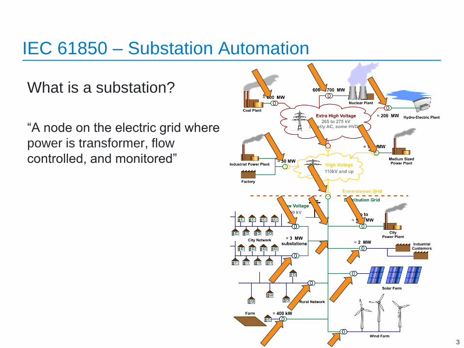
What is a substation?
“A node on the electric grid where
power is transformer, flow
controlled, and monitored”
IEC 61850 – Substation Automation
3
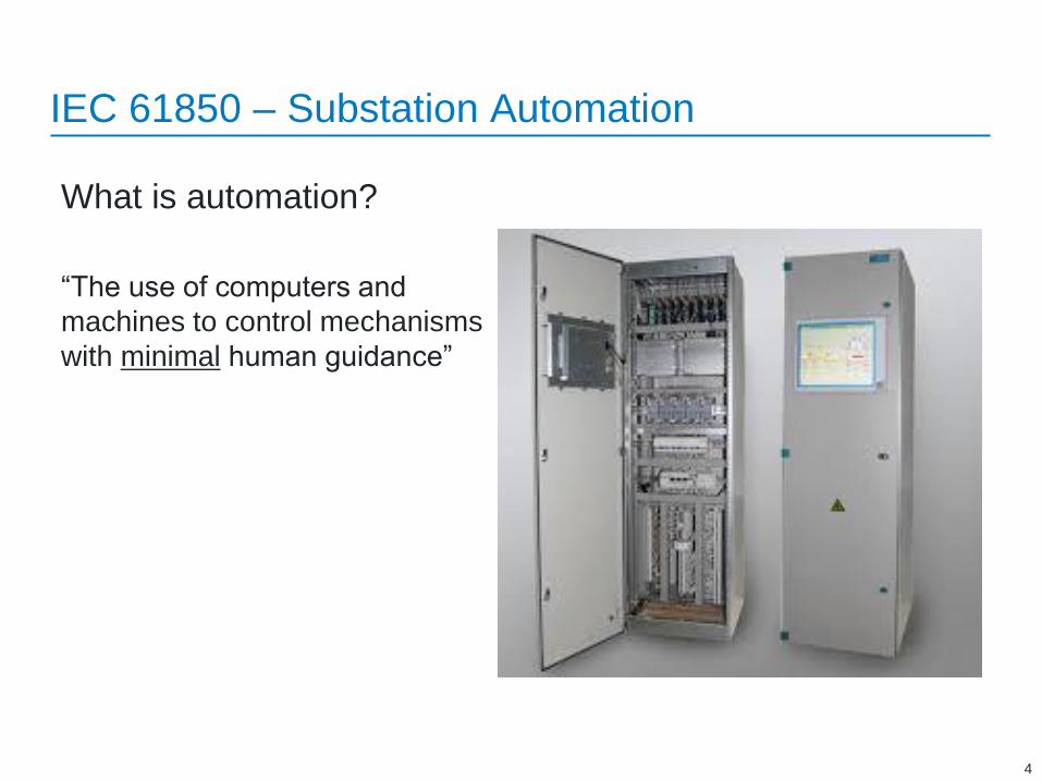
What is automation?
“The use of computers and
machines to control mechanisms
with minimal human guidance”
IEC 61850 – Substation Automation
4
IEC 61850 – Substation Automation
5
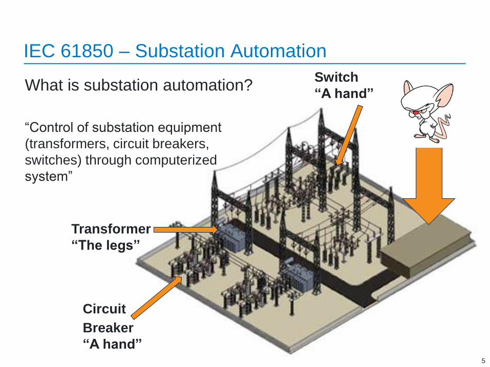
What is substation automation?
“Control of substation equipment
(transformers, circuit breakers,
switches) through computerized
system”
Circuit
Breaker
“A hand”
Switch
“A hand”
Transformer
“The legs”
Control
House
IEC 61850 is a standard for substation automation communication
aka – how does “the brain” communicate
Goals of IEC 61850
A communication protocol designed to model the entire station
“Defines the rules of engagement for communication in a substation”
Promotion of high inter-operability between systems from different vendors
“Vendor agnostic – same rules regardless of the manufacturer”
A communication protocol that can be made future proof
“Network based – similar to an office computer network”
Define testing required to ensure equipment conforms to the standard
“How are you sure that everyone is playing by the same rules”
IEC 61850 – Substation Automation
6

IEC 61850 – Substation Automation
Network Based Communication
Analog (CT/PT) and discrete
signals (contacts/trip/close) are
transmitted over IT-based
networks
Communication paths “wiring”
and logic is defined in software
in lieu of physical wiring
7
The Premise
Non-propriety, secure, and reliable network
communication within a electric substation
IEC 61850 – Substation Automation
8
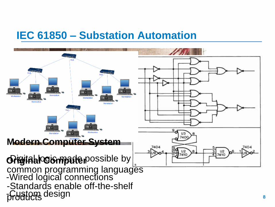
Original Computer
-Wired logical connections
-Custom design
Modern Computer System
-Digital logic made possible by
common programming languages
-Standards enable off-the-shelf
products
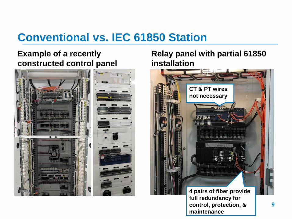
Conventional vs. IEC 61850 Station
Example of a recently
constructed control panel
Relay panel with partial 61850
installation
9
CT & PT wires
not necessary
4 pairs of fiber provide
full redundancy for
control, protection, &
maintenance
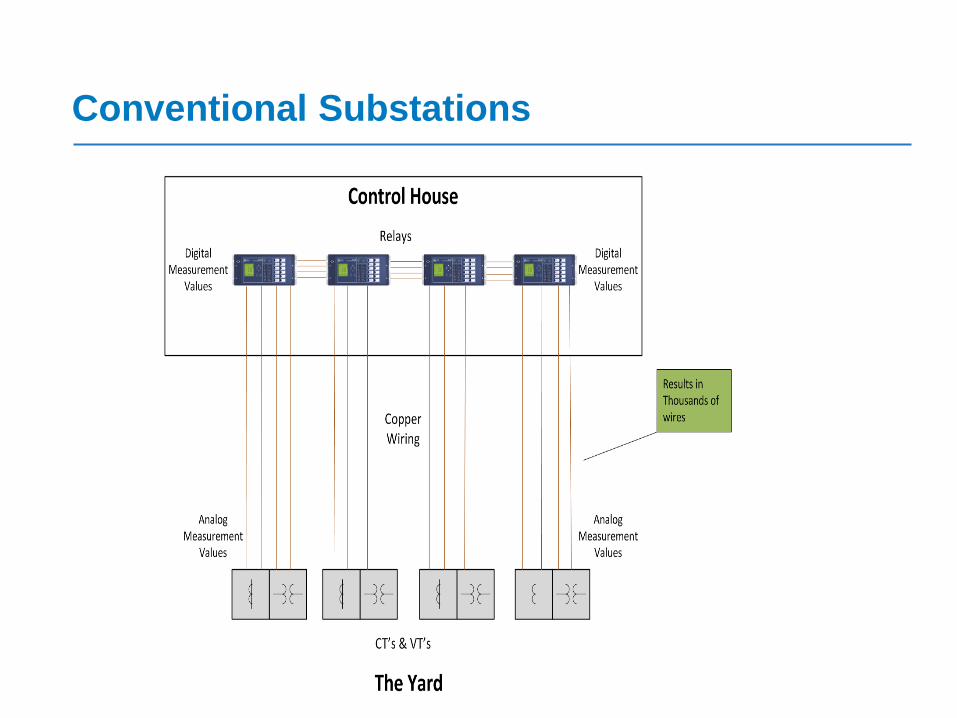
Conventional Substations

An IEC 61850 Approach

Labor intensive and
expensive wiring
Limited performance and
data transmission
capabilities
Simplified and cost-
effective
Enhanced performance
and data transmission
capabilities
Wiring Comparison
Conventional IEC 61850

IEC 61850 – Digital Control System
Digital Control/Protection System
Control is performed over
network through digital devices
(HMIs, relays, etc.)
Test switches are not needed
in the control house as
voltages and currents are
converted to digital signals in
the yard
Panel reduction and therefore
control house size reduction
13

Digital Control System Example
In-Use Digital Control
System
• Breaker Control
Screen14

IEC 61850 System Example
In-Use Digital Control @
Nearby Utility
• Breaker Control
Screen15
System 1 relay package for a 345 kV switching
station. This control house is smaller than
many medium-voltage metal-clads
Hundreds/thousands of
copper wires in a traditional
station are replaced with a few
fiber optic cables.
Cabling between system 1 and 2
control panels
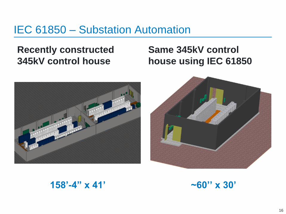
Recently constructed
345kV control house
Same 345kV control
house using IEC 61850
16
158’-4” x 41’ ~60’’ x 30’
IEC 61850 – Substation Automation

17
IEC 61850 – Substation Automation History
Today there are 28 separate
documents under IEC 61850 alone,
along with supplemental material
from IEEE and CIGRE
2012 – First
Ed. 2 relays
released
18
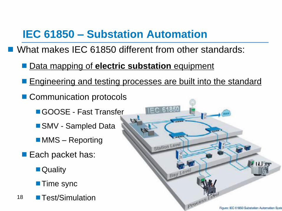
What makes IEC 61850 different from other standards:
Data mapping of electric substation equipment
Engineering and testing processes are built into the standard
Communication protocols
GOOSE - Fast Transfer
SMV - Sampled Data
MMS – Reporting
Each packet has:
Quality
Time sync
Test/Simulation
IEC 61850 – Substation Automation

Communication
19
Dial “61850” for help
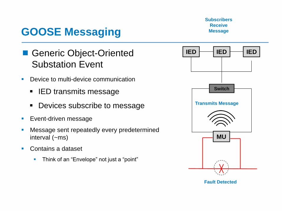
GOOSE Messaging
Generic Object-Oriented
Substation Event
Device to multi-device communication
IED transmits message
Devices subscribe to message
Event-driven message
Message sent repeatedly every predetermined
interval (~ms)
Contains a dataset
Think of an “Envelope” not just a “point”
IED
MU
IEDIED
Fault Detected
Transmits Message
Subscribers
Receive
Message
Switch
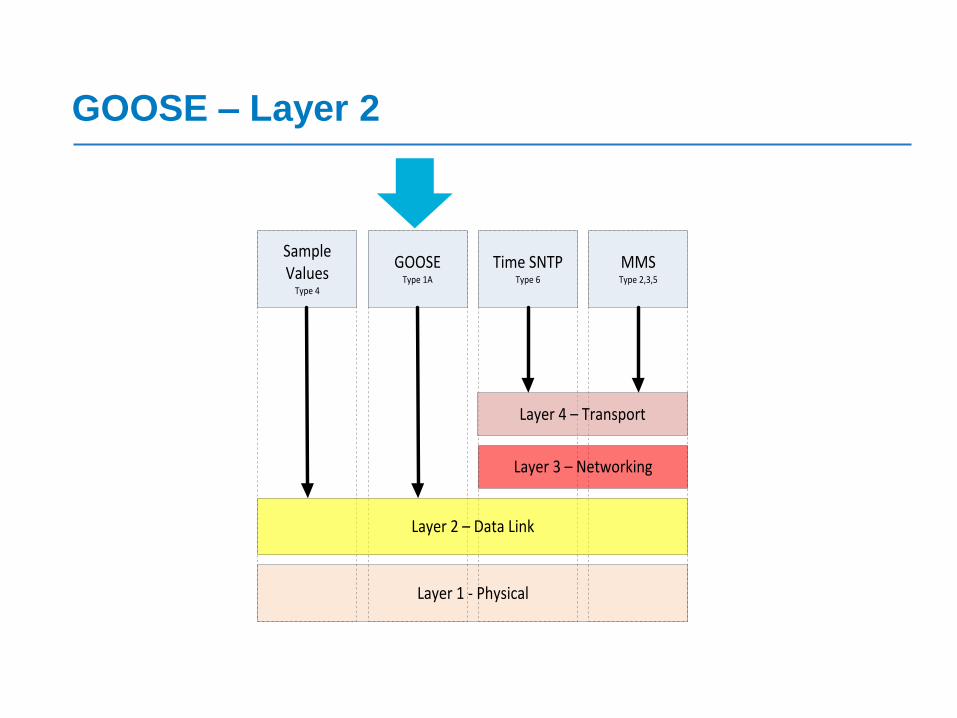
GOOSE – Layer 2
Layer 1 - Physical
Sample Values
Type 4
GOOSEType 1A
Time SNTPType 6
MMSType 2,3,5
Layer 2 – Data Link
Layer 3 – Networking
Layer 4 – Transport

Publisher-Subscriber Model
Messaging pattern to categorize
and filter data
Publisher – sends data to a network
Subscriber – subscribes to a specified type
of data
Publisher
Subscriber
Process Bus
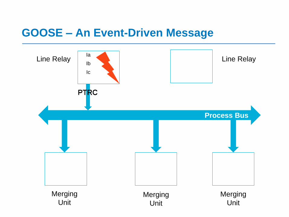
GOOSE – An Event-Driven Message
Merging
UnitMerging
Unit
Merging
Unit
Line RelayIa
Ib
Ic
Line Relay
PTRCPTRCPTRC
Process Bus
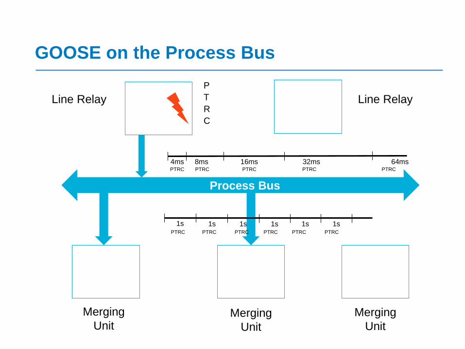
GOOSE on the Process Bus
Merging
UnitMerging
Unit
Merging
Unit
Line Relay Line Relay
P
T
R
C
4ms 8ms 16ms 32ms 64ms
1s 1s 1s 1s 1s 1s
PTRC PTRC PTRC PTRC PTRC
PTRC PTRC PTRC PTRC PTRC PTRC

Sampled Values
Time-Sampled Data from CTs & VTs
Sent from merging units to relays
Multicast messages sent over
Ethernet
For protection – 80 samples per
cycle with 4 currents and 4 voltages
in the stream, 256 samples/cycle for
metering/fault analysis
Addressed in IEC 61850 9-2
(clarified in 9-2LE)
MU
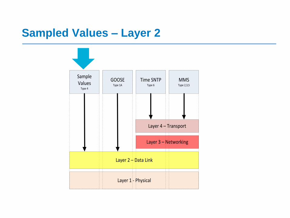
Sampled Values – Layer 2
Layer 1 - Physical
Sample Values
Type 4
GOOSEType 1A
Time SNTPType 6
MMSType 2,3,5
Layer 2 – Data Link
Layer 3 – Networking
Layer 4 – Transport
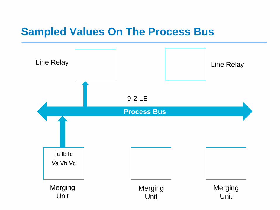
Sampled Values On The Process Bus
Process Bus
Merging
UnitMerging
Unit
Merging
Unit
Line Relay
Ia Ib Ic
Va Vb Vc
Line Relay
9-2 LE
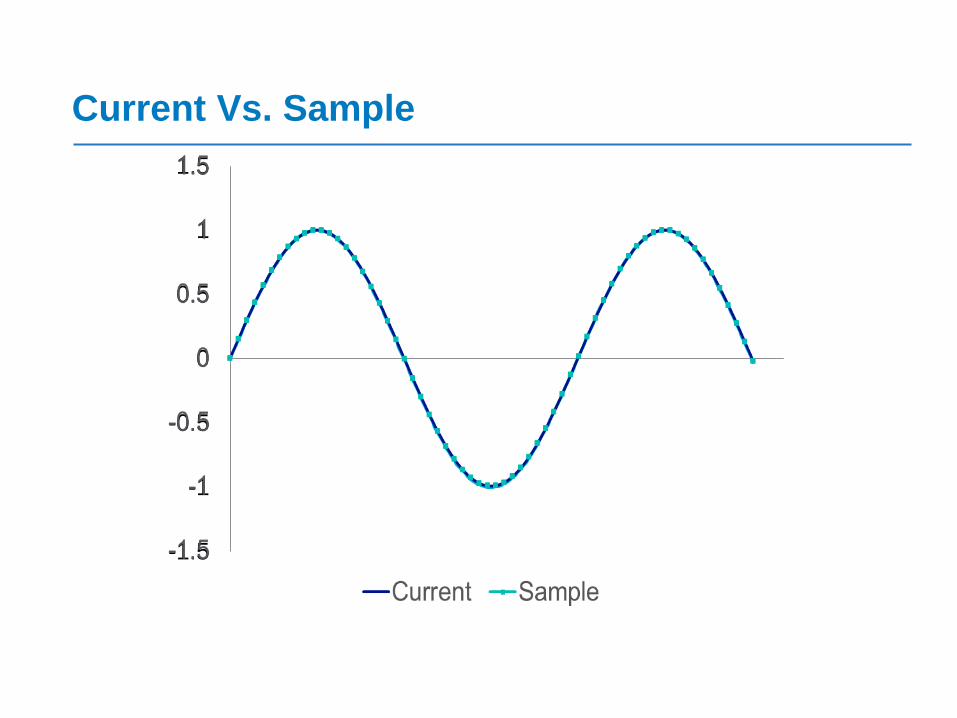
Current Vs. Sample
-1.5
-1
-0.5
0
0.5
1
1.5
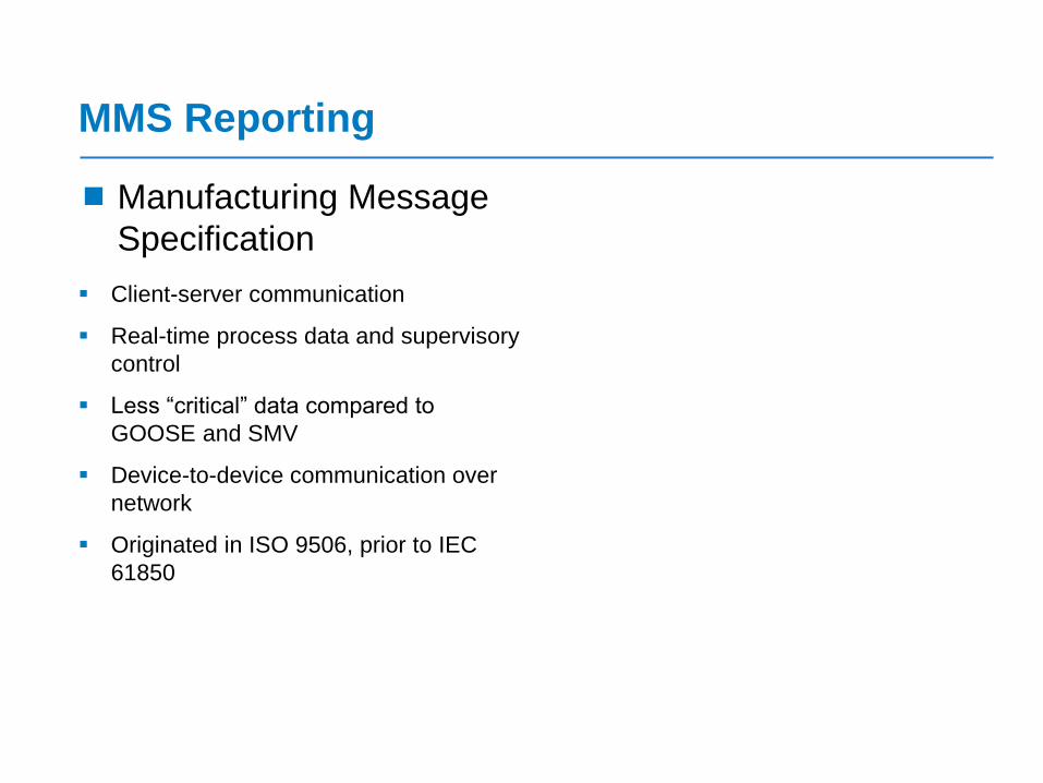
MMS Reporting
Manufacturing Message
Specification
Client-server communication
Real-time process data and supervisory
control
Less “critical” data compared to
GOOSE and SMV
Device-to-device communication over
network
Originated in ISO 9506, prior to IEC
61850

MMS – Layer 4
Layer 1 - Physical
Sample Values
Type 4
GOOSEType 1A
Time SNTPType 6
MMSType 2,3,5
Layer 2 – Data Link
Layer 3 – Networking
Layer 4 – Transport
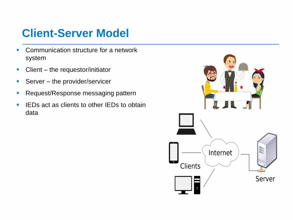
Client-Server Model
Communication structure for a network
system
Client – the requestor/initiator
Server – the provider/servicer
Request/Response messaging pattern
IEDs act as clients to other IEDs to obtain
data
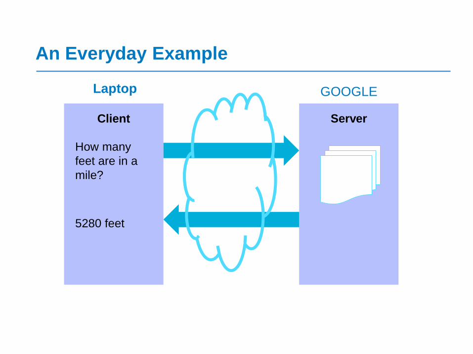
An Everyday Example
Client Server
Laptop GOOGLE
How many
feet are in a
mile?
5280 feet
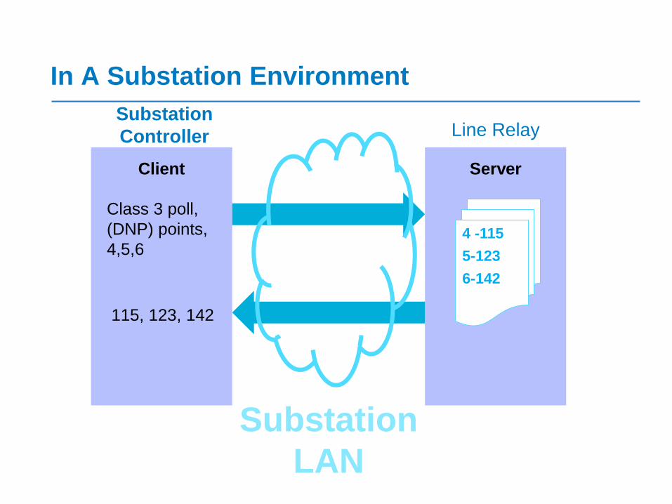
In A Substation Environment
Client Server
Substation
Controller Line Relay
Class 3 poll,
(DNP) points,
4,5,64 -115
5-123
6-142
115, 123, 142
Substation
LAN

MMS Operation
Type 1 – Fast messages
Type 1A – Trip
Type 2 – Medium speed messages
Type 3 – Low speed messages
Type 4 – Raw data messages
Type 5 – File transfer functions
Type 6 – Time synchronization
messages
Data Map
35
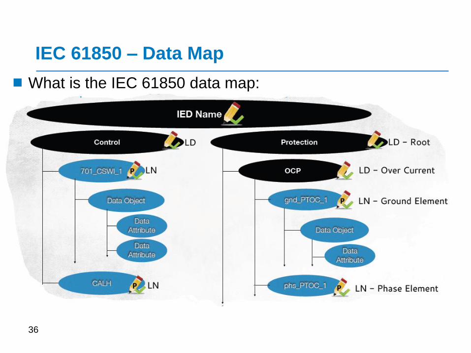
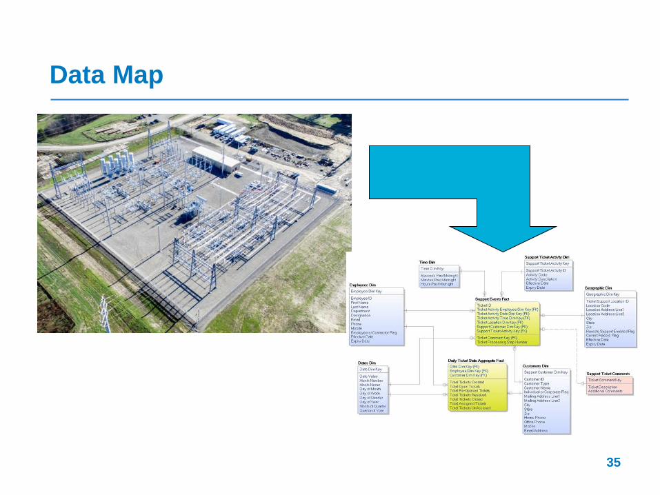
IEC 61850 – Data Map
36
What is the IEC 61850 data map:
IEC 61850 – Data Map
37
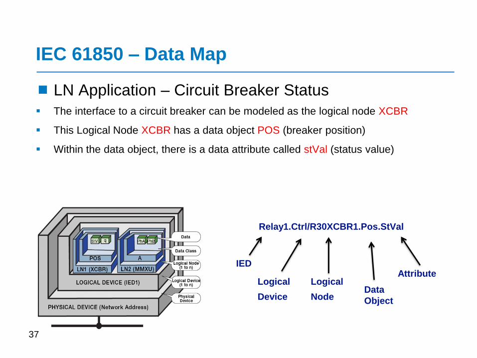
LN Application – Circuit Breaker Status
The interface to a circuit breaker can be modeled as the logical node XCBR
This Logical Node XCBR has a data object POS (breaker position)
Within the data object, there is a data attribute called stVal (status value)
Relay1.Ctrl/R30XCBR1.Pos.StVal
IED
Logical
Device
Logical
NodeData
Object
Attribute
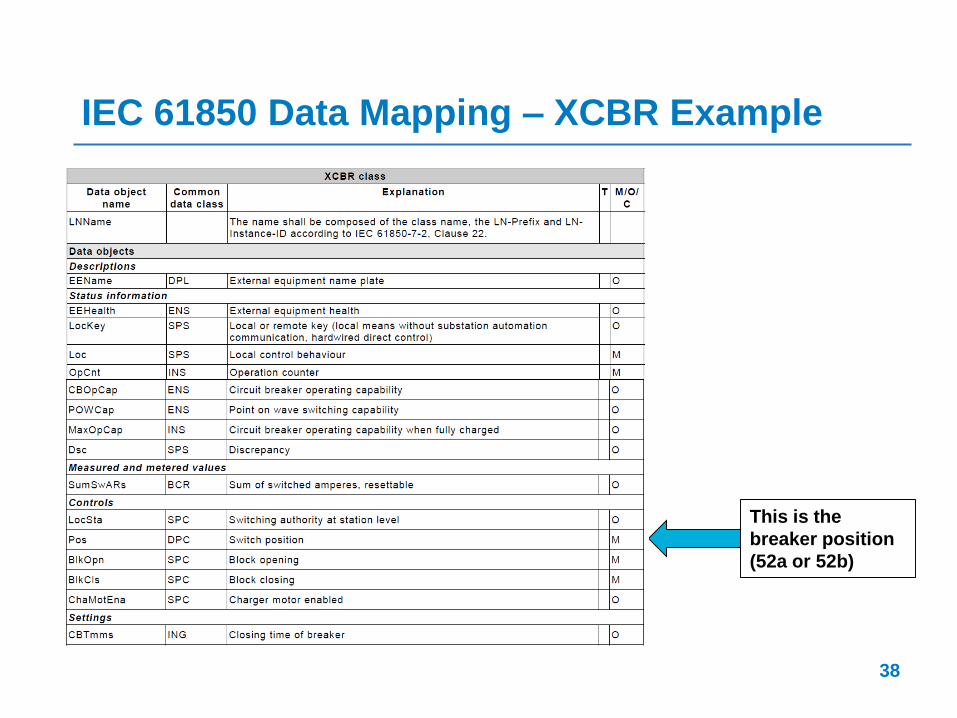
IEC 61850 Data Mapping – XCBR Example
38
This is the
breaker position
(52a or 52b)
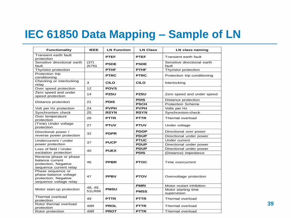
IEC 61850 Data Mapping – Sample of LN
39
Functionality IEEE LN Function LN Class LN class naming
Transient earth fault protection
PTEF PTEF Transient earth fault
Sensitive directional earth fault
(37) (67N)
PSDE PSDE Sensitive directional earth fault
Thyristor protection PTHF PTHF Thyristor protection
Protection trip conditioning
PTRC PTRC Protection trip conditioning
Checking or interlocking relay
3 CILO CILO Interlocking
Over speed protection 12 POVS
Zero speed and under speed protection
14 PZSU PZSU Zero speed and under speed
Distance protection 21 PDIS PDIS Distance protection
PSCH Protection Scheme
Volt per Hz protection 24 PVPH PVPH Volts per Hz
Synchronism check 25 RSYN RSYN Synchronism-check
Over temperature protection
26 PTTR PTTR Thermal overload
(Time) Under voltage protection
27 PTUV PTUV Under voltage
Directional power / reverse power protection
32 PDPR PDOP Directional over power
PDUP Directional under power
Undercurrent / under power protection
37 PUCP PTUC Under current
PDUP Directional under power
Loss of field / Under excitation protection
40 PUEX PDUP Directional under power
PDIS (Distance) impedance
Reverse phase or phase balance current protection, Negative sequence current relay
46 PPBR PTOC Time overcurrent
Phase sequence or phase-balance voltage protection, Negative sequence voltage relay
47 PPBV PTOV Overvoltage protection
Motor start-up protection 48, 49, 51LR66
PMSU PMRI Motor restart inhibition
PMSS Motor starting time supervision
Thermal overload protection
49 PTTR PTTR Thermal overload
Rotor thermal overload protection
49R PROL PTTR Thermal overload
Rotor protection 49R PROT PTTR Thermal overload
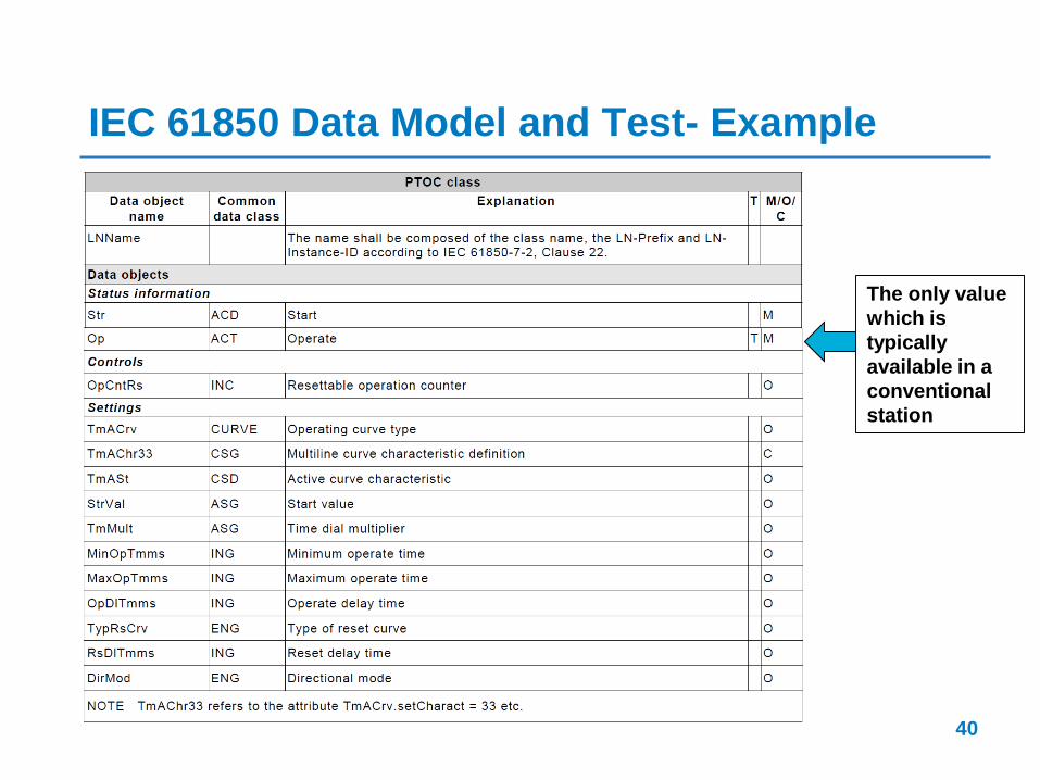
IEC 61850 Data Model and Test- Example
40
The only value
which is
typically
available in a
conventional
station

IEC 61850 Data Mapping - Example
41
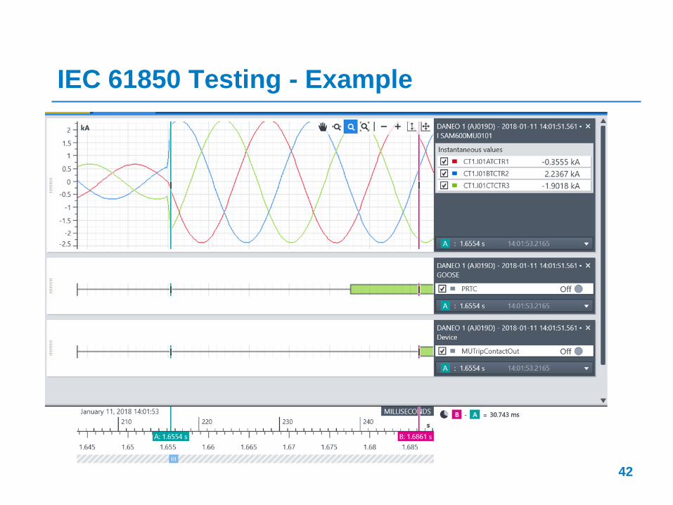
IEC 61850 Testing - Example
42
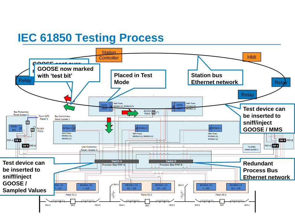
IEC 61850 Testing Process
43
HMI
Station
Controller HMI
Relay Relay
Relay
Placed in Test
Mode
Redundant
Process Bus
Ethernet network
Station bus
Ethernet network
Test device can
be inserted to
sniff/inject
GOOSE /
Sampled Values
GOOSE sent over
networkGOOSE now marked
with ‘test bit’
Test device can
be inserted to
sniff/inject
GOOSE / MMS
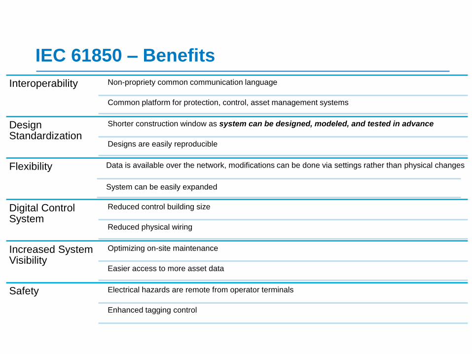
IEC 61850 – Benefits
Interoperability Non-propriety common communication language
Common platform for protection, control, asset management systems
Design Standardization
Shorter construction window as system can be designed, modeled, and tested in advance
Designs are easily reproducible
Flexibility Data is available over the network, modifications can be done via settings rather than physical changes
System can be easily expanded
Digital Control System
Reduced control building size
Reduced physical wiring
Increased System Visibility
Optimizing on-site maintenance
Easier access to more asset data
Safety Electrical hazards are remote from operator terminals
Enhanced tagging control
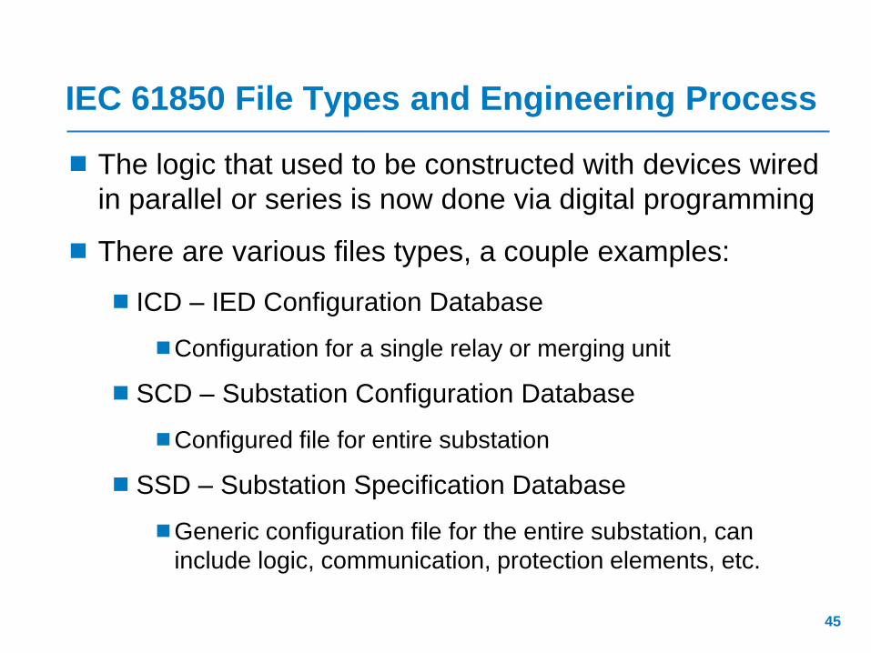
IEC 61850 File Types and Engineering Process
The logic that used to be constructed with devices wired
in parallel or series is now done via digital programming
There are various files types, a couple examples:
ICD – IED Configuration Database
Configuration for a single relay or merging unit
SCD – Substation Configuration Database
Configured file for entire substation
SSD – Substation Specification Database
Generic configuration file for the entire substation, can
include logic, communication, protection elements, etc.
45
46
Bottom-Up Engineering
Top-Down Engineering
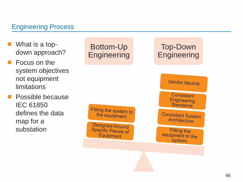
Engineering Process
What is a top-
down approach?
Focus on the
system objectives
not equipment
limitations
Possible because
IEC 61850
defines the data
map for a
substation

Top-Down vs. Bottom-Up Engineering
Goal of using a Top-Down design:
1. Standardized engineering process
2. Repeatability
3. Vendor inter-operability
Reality:
1. Mix of top-down and bottom-up
2. Standards based on top-down approach, but of the system
will need to be customized based on equipment limitations
47
Engineering Process
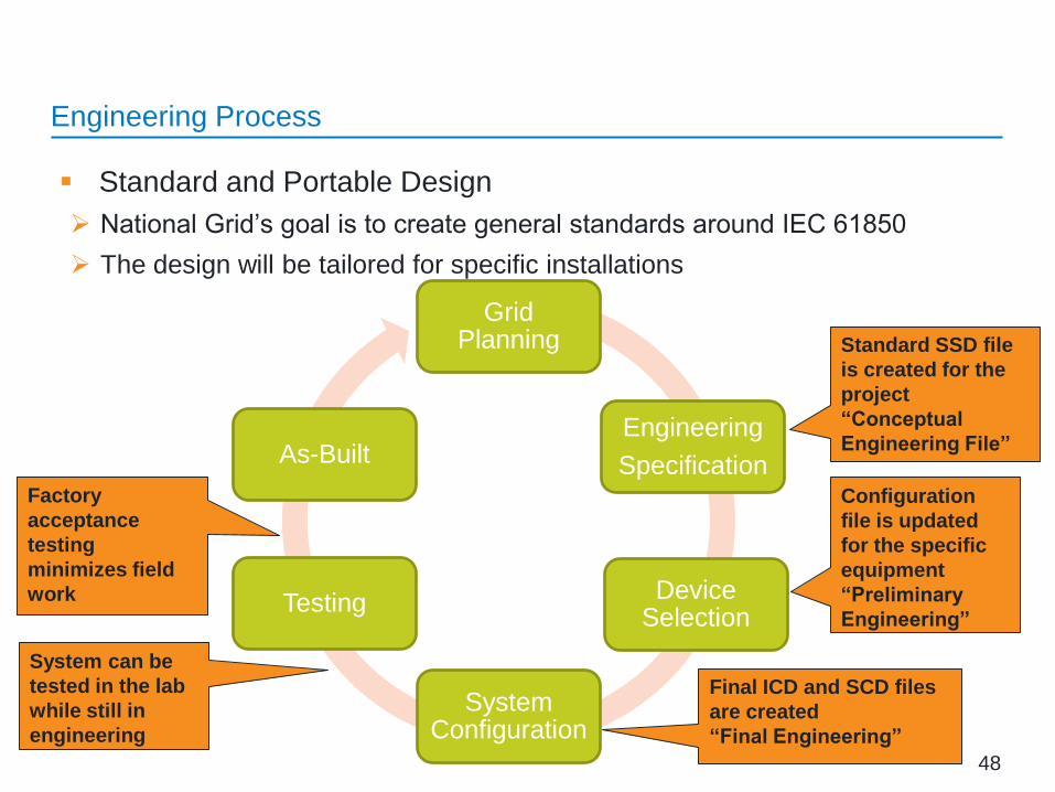
Standard and Portable Design
National Grid’s goal is to create general standards around IEC 61850
The design will be tailored for specific installations
48
Engineering Process
Grid Planning
Engineering
Specification
Device Selection
System Configuration
Testing
As-Built
Standard SSD file
is created for the
project
“Conceptual
Engineering File”
Configuration
file is updated
for the specific
equipment
“Preliminary
Engineering”
System can be
tested in the lab
while still in
engineering
Factory
acceptance
testing
minimizes field
work
Final ICD and SCD files
are created
“Final Engineering”

IEC 61850 – Substation Automation
49
Why would we want to change the
status quo?
– Decreased capital cost
– Smaller footprint
– Increased flexibility and visibility
– Proactive condition-based
maintenance and remote access

IEC 61850 – Benefits
50
Interoperability Non-propriety common communication language
Common platform for protection, control, asset management systems
Design Standardization
Shorter construction window as system can be designed, modeled, and tested in advance
Designs are easily reproducible
Flexibility Data is available over the network, modifications can be done via settings rather than physical changes
System can be easily expanded
Digital Control System
Reduced control building size
Reduced wiring
Increased System Visibility
Optimizing on-site maintenance
Easier access to more asset data
Safety Electrical hazards are remote from operator terminals
Enhanced tagging control

IEC 61850 – Risks
51
Cyber-Security Network connectivity, all devices connected to the network are potentially accessible
The network can be a single point of failure if not properly designed
Patch management requirements are greatly increased
New Technology
Some concepts are not fully proven in the field
Not all vendors offer compatible products
Limited available workforce
Engineering & Operational Learning
New standards and work methods are required
Cross discipline skillsets are not available for example, most protection engineers are not familiar with VLANS or MAC addresses
IEC 61850 – Substation Automation
In Summary…
Packet-based network communication for electric power
systems
Reduced control house size, reduced wiring,
standardized design, reduced operational costs
IEC 61850 considers the entire system lifecycle;
engineering, construction, operations
Potential new challenges that have to be addressed
– Coordination between engineers and operations is critical
52

IEC 61850 – Substation Automation
1.) What were the standard committee’s goals in the
development of the IEC 61850 standard?
Answer:
– Data mapping of the entire substation;
– Future-proof communication;
– Vendor interoperability;
– A common means of storing data,
– Defining testing for conformance to the standard
53
IEC 61850 – Substation Automation
2.) What are some of the advantages in transitioning to an
IEC 61850 digital substation?
Answer:
– Interoperability
– Design standardization
– System flexibility
– Reduced capital costs
– Reduced operational costs
– Increased system visibility
– Enhanced safety
54
IEC 61850 – Substation Automation
3.) What are the risks with digital substations?
Answer:
– Cyber-security
– New technology
– Engineering and operational learning curve
55
IEC 61850 – Substation Automation
A couple questions
4.) How are the potential risks with digital substations
being mitigated?
Answer:
– Design with security in mind
– Compartmentalized networks
– Extensive collaboration between engineering and operations
56
IEC 61850 – Substation Automation
A couple questions
5.) Does IEC 61850 have a technical, commercial, or
organizational impact?
Answer:
– All of the above! To fully realize the benefits, transitioning to a
digital substation requires complete organizational buy-in
57
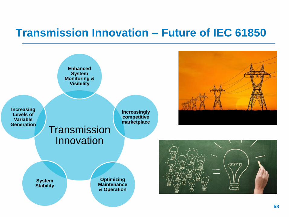
Transmission Innovation – Future of IEC 61850
58
Transmission Innovation
Enhanced System
Monitoring & Visibility
Increasingly competitive marketplace
Optimizing Maintenance & Operation
System Stability
Increasing Levels of Variable
Generation
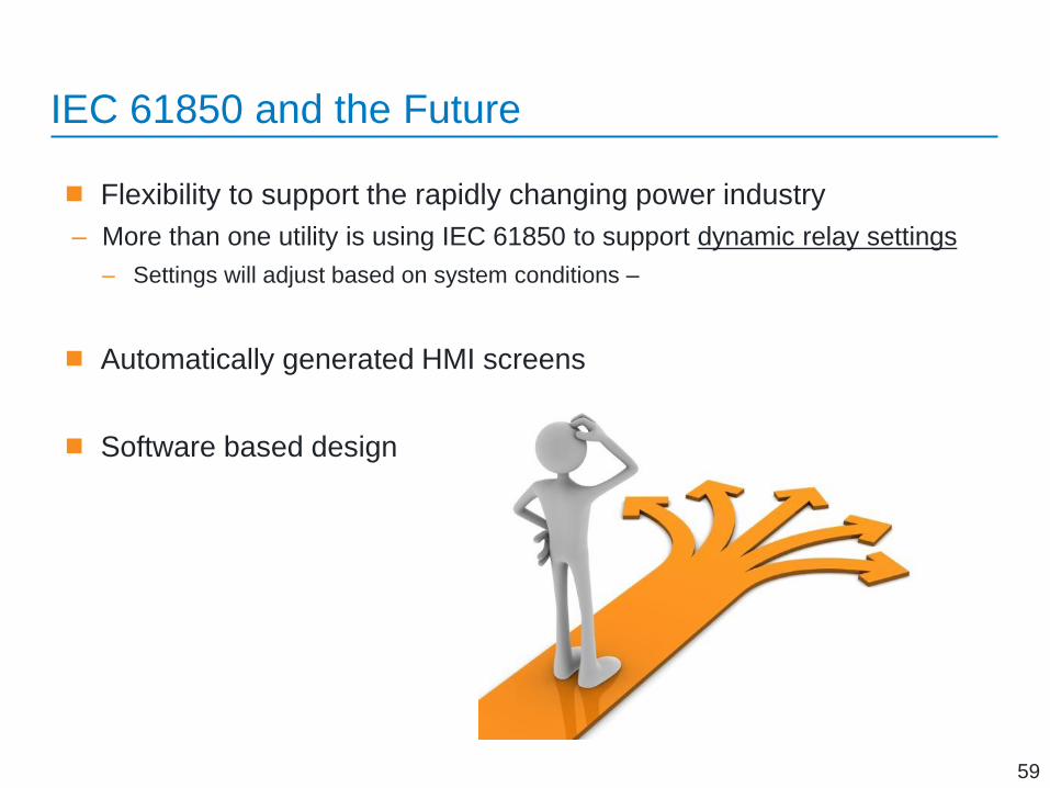
IEC 61850 and the Future
Flexibility to support the rapidly changing power industry
– More than one utility is using IEC 61850 to support dynamic relay settings
– Settings will adjust based on system conditions –
Automatically generated HMI screens
Software based design
59

Thank You The first GOOSE caught on our
network analyzer
1. Ethernet-based
communication on IEC 61850
2. Digitalization of analog
protection elements
3. Asset management support
4. Integrated engineering
5. Cyber Security - Prerequisite
of any digital substation
6. Network control support
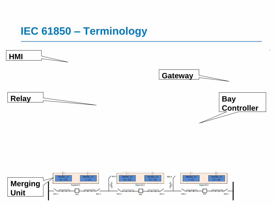
IEC 61850 – Terminology
61
Merging
Unit
Relay Bay
Controller
HMI
Gateway