Embed Size (px)
Citation preview


IDS X64 Remote Receiver 700-408-02A Issued August 2010 2
IDS X64 Remote Receiver 700-408-02A Issued August 2010 3
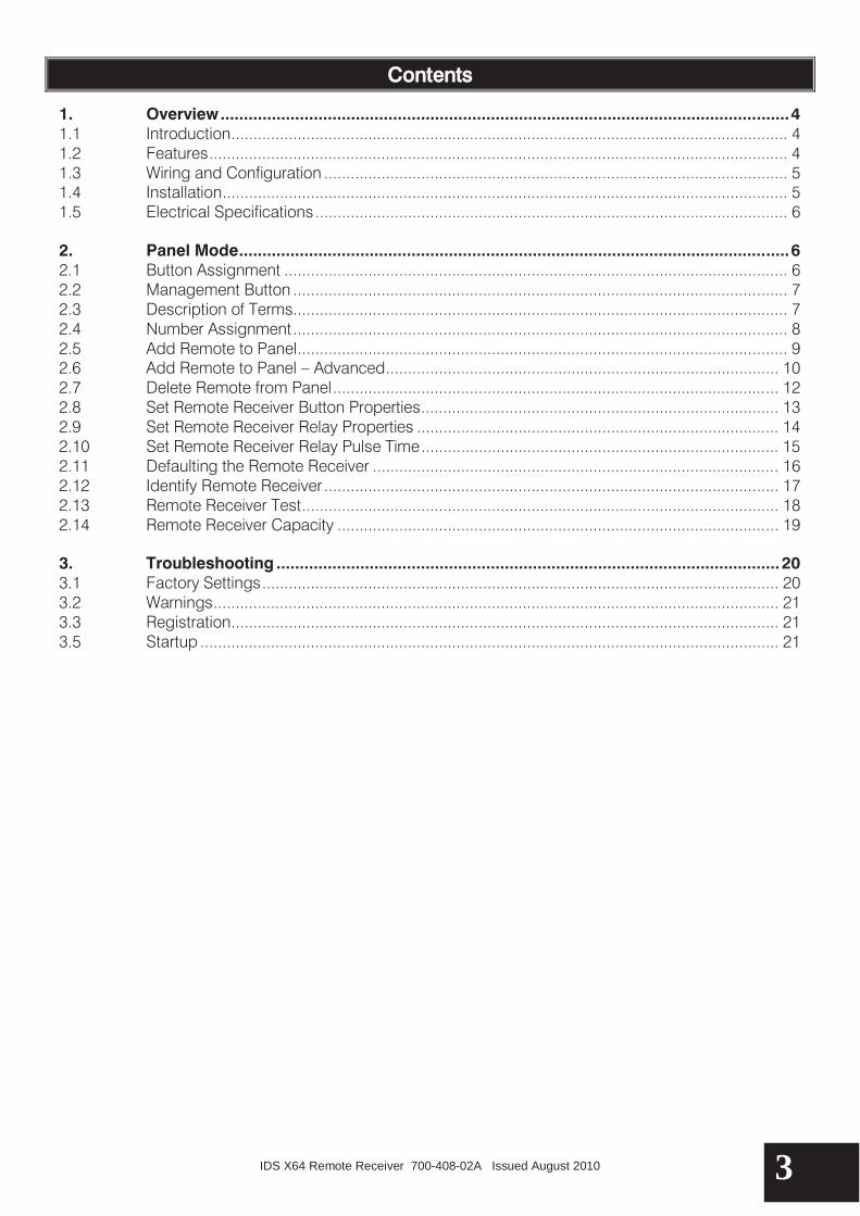
Contents
1. Overview .......................................................................................................................... 4 1.1 Introduction .............................................................................................................................. 4 1.2 Features ................................................................................................................................... 4 1.3 Wiring and Configuration ......................................................................................................... 5 1.4 Installation ................................................................................................................................ 5 1.5 Electrical Specifications ........................................................................................................... 6 2. Panel Mode ...................................................................................................................... 6 2.1 Button Assignment .................................................................................................................. 6 2.2 Management Button ................................................................................................................ 7 2.3 Description of Terms................................................................................................................ 7 2.4 Number Assignment ................................................................................................................ 8 2.5 Add Remote to Panel ............................................................................................................... 9 2.6 Add Remote to Panel – Advanced ......................................................................................... 10 2.7 Delete Remote from Panel ..................................................................................................... 12 2.8 Set Remote Receiver Button Properties ................................................................................. 13 2.9 Set Remote Receiver Relay Properties .................................................................................. 14 2.10 Set Remote Receiver Relay Pulse Time ................................................................................. 15 2.11 Defaulting the Remote Receiver ............................................................................................ 16 2.12 Identify Remote Receiver ....................................................................................................... 17 2.13 Remote Receiver Test ............................................................................................................ 18 2.14 Remote Receiver Capacity .................................................................................................... 19 3. Troubleshooting ............................................................................................................ 20 3.1 Factory Settings ..................................................................................................................... 20 3.2 Warnings ................................................................................................................................ 21 3.3 Registration ............................................................................................................................ 21 3.5 Startup ................................................................................................................................... 21

Section: 1
IDS X64 Remote Receiver 700-408-02A Issued August 2010 4
1. Overview
1.1 Introduction
The IDS X64 Remote Receiver is a 433.92 MHz RF receiver that is designed to connect to an IDS X64 Alarm Panel. The receiver connects to the keypad Bus (via D+ and D- terminals), permitting the Alarm Panel to be armed and disarmed from Remote Transmitters. When remotes are learnt, they are assigned to USER CODES stored in the IDS Alarm Panel. This means that the Alarm Panel is able to log ARM/DISARM events per user. The Remote Receiver enables users of an X64 system to remotely operate essential functions of the X64 Alarm Panel by pushing buttons on Remote Transmitters. The Remote Receiver gives the X64 system users the convenience of pressing a Remote Transmitter button instead of going to the keypad; it gives each user the additional security of carrying their own panic button. The X64 Alarm Panel functions, which can be operated via a Remote Receiver, are arm/disarm, stay arm, and panic. The Remote Receiver also provides two relays that can be operated by Remote Transmitters, which can be used to operate gates or lights.
1.2 Features
A maximum of 128 remotes in default mode. Three LEDs for communication. Support for Bus-wired operation. Communicates with the Alarm Panel via a RS485 keypad Bus. Onboard tamper switch. The X64 Alarm Panel supports up to 4 Remote Receivers The action(s) for the Remote Transmitter buttons can be configured as any non-conflicting
combination of arm/disarm; stay arm, panic, relay1, relay2, or no action. If none of the Remote Transmitter buttons are assigned as "Panic", then holding any button of a
known Remote Transmitter for 3 seconds or more will cause a "Panic" condition. If a Remote Transmitter button is assigned to “Panic”, then pushing that button is the only way to cause remote “Panic”.
Each Remote Receiver offers two Remote Transmitter controlled outputs which may operate (within their ratings) lights or gates.
The Remote Receiver is NOT waterproof or dustproof. It should be protected from rain and contaminants. It may be sealed with silicone or adhesive tape. Its components generate a bit of heat, and their warmth will attract cockroaches. It should be cleaned once or twice a year, preferably by a soft brush and compressed air.

Section: 1
IDS X64 Remote Receiver 700-408-02A Issued August 2010 5
1.3 Wiring and Configuration
NOTE: The amber LED will be a steady on when it is connected to the Bus. If it is off, then there is a problem. The green LED flashes when in standby mode.
1.4 Installation
Choose a location for the Remote Receiver:
as high as possible accessible for installation and maintenance accessible for X64 wiring accessible for wiring to controlled devices suitable for antenna
1. Straighten the antenna. It should not be kinked or coiled or rolled into a ball, and it should not lie
against metal. Hanging is best, but lying on wood is also fine. 2. Mount the Remote Receiver, using fasteners (woodscrews etc) through the tabs at each end of
the base plate. 3. Remove the Remote Receiver cover. 4. The power and data terminals of the Remote Receiver should be connected to the
corresponding terminals of the X64 Alarm Panel, or the nearest keypad or zone expander. To avoid mistakes, use sheathed cable with 4 colour-coded cores, and connect identically at each end:
12V RED GND BLACK

Section: 1
IDS X64 Remote Receiver 700-408-02A Issued August 2010 6
D+ WHITE D- GREEN
(These colours are only a guideline). 5. Equipment to be remotely switched should be connected to the RELAY1 and RELAY2 terminals
of the Remote Receiver. The relay current ratings (see section 1.5) must not be exceeded. If the Remote Receiver relays are configured as "secure", the effective terminals for "NC" (Normally Closed) and "NO" (Normally Open) will be swapped.
6. Keep the Remote Receiver cover off during configuration, so that the DIPswitches are accessible and the LEDs are visible.
7. When configuration is complete and the Remote Receiver is working, replace the cover.
1.5 Electrical Specifications
Supply Voltage: 10 to 15 VDC
Current Consumption: 30mA
Relay Rating Contacts: 1 A @ 30 VDC
Minimum Receiver Sensitivity: ≤ -100 dBm Receiver Frequency: 433.92 MHz
2. Panel Mode
These settings only apply to receivers being used with the IDS X64 Alarm Panel. All remotes follow these settings; they cannot be different from one remote to the next.
2.1 Button Assignment
The functions that can be assigned to a button are: arm/disarm, stay, relay 1, and relay 2. Each button can be assigned multiple functions, or no function. It cannot be assigned both arm/disarm and stay. Different buttons can be assigned the same function. The factory defaults for the buttons are as follows:
Button 1: Arm/Disarm Button 2: no function

Section: 2
IDS X64 Remote Receiver 700-408-02A Issued August 2010 7
Button 3: Stay Arm Button 4: no function
NOTE: When any button is held down for 3 seconds, the panel goes into panic mode. Pressing the arm/disarm button does NOT cancel the panic. The panic needs to be cancelled at the keypad.
2.2 Management Button
The management button allows for the ability to assign more than one user per remote. You can also have two users from two different partitions on the same remote. This is done by the Remote Receiver's "Add Remote to Panel - Advanced" menu, by specifying the number of the desired button (0, 1, 2, 3, or 4). A button designated as such, will perform the arm/disarm function, with the configured User Code, which must be different from the remote's default User Code. EXAMPLE: You have assigned your user code to button 1 to arm/disarm the Alarm Panel. You might want to add a second user code to a button to arm/disarm. The second code might be the maid’s code. You will then use the management button to add another user code to arm/disarm the system to button 2. If Remote Receiver 1 assigns arm/disarm to button 1, and Remote Receiver 2 assigns Stay to button 1, a remote is added to both Remote Receivers, and both Remote Receivers receive the signal when the remote's button 1 is pushed, then one Remote Receiver will send an arm/disarm command while the other sends a Stay command. If the commands go to different partitions, the result is confusing; if they go to the same partition, the result is conflict. It is therefore recommended that all Remote Receivers of a system have identical default button function assignments. NOTE:
If you choose 0 for your multi-user assignment, it will “default” the buttons on the remote that have not already been given a multi-user assignment. What this means, is that it will basically revert the remote back to how it looks on the picture on page 6. 0 can also be used to teach properties to buttons on a remote. These properties can then be carried over to other remotes on the same receiver that are taught 0 as their multi user assignment.
Whenever a management button is trained, then that button will ONLY arm/disarm for the code assigned to it. It will NOT do any of the following:
Send an immediate panic. (After 3 seconds, it will). Stay arm. Trigger any relays.
2.3 Description of Terms
Throughout the manual the use of the following terms is used to describe information that appears on the LCD keypad during programming:
N – Remote Receiver Number B – Button Number R – Relay Number RS – Relay State

Section: 2
IDS X64 Remote Receiver 700-408-02A Issued August 2010 8
UUUU – User Code RR – Remote Receiver Record Number UUU – Number of Users TTTT – Pulse Time RT – Remote Receiver
These terms will be used in bold in the document so that they can stand out.
2.4 Number Assignment
Each Remote Receiver must be assigned a number to specify the destination of commands from the panel. Allowable Remote Receiver numbers are 1, 2, 3, or 4. Each Remote Receiver must have a different number; multiple assignments of a Remote Receiver number will cause system failure. The Remote Receiver number is set by the Remote Receiver DIPswitches: 1 2 3 4 All other DIPswitch settings cause the Remote Receiver to wait with the red LED quick-flashing in groups of three.
R R R R R R R R R R R R R R R until the DIPswitch is changed to a valid number. The Remote Receiver then restarts normally.
Section: 2
IDS X64 Remote Receiver 700-408-02A Issued August 2010 9
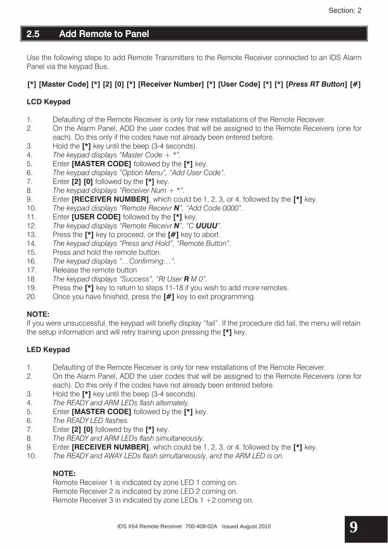
2.5 Add Remote to Panel
Use the following steps to add Remote Transmitters to the Remote Receiver connected to an IDS Alarm Panel via the keypad Bus. [*] [Master Code] [*] [2] [0] [*] [Receiver Number] [*] [User Code] [*] [*] [Press RT Button] [#]
LCD Keypad 1. Defaulting of the Remote Receiver is only for new installations of the Remote Receiver. 2. On the Alarm Panel, ADD the user codes that will be assigned to the Remote Receivers (one for
each). Do this only if the codes have not already been entered before. 3. Hold the [*] key until the beep (3-4 seconds). 4. The keypad displays “Master Code + *”. 5. Enter [MASTER CODE] followed by the [*] key. 6. The keypad displays “Option Menu”, “Add User Code”. 7. Enter [2] [0] followed by the [*] key. 8. The keypad displays “Receiver Num + *”. 9. Enter [RECEIVER NUMBER], which could be 1, 2, 3, or 4, followed by the [*] key. 10. The keypad displays “Remote Receivr N”, “Add Code 0000”. 11. Enter [USER CODE] followed by the [*] key. 12. The keypad displays “Remote Receivr N”, “C UUUU”. 13. Press the [*] key to proceed, or the [#] key to abort. 14. The keypad displays “Press and Hold”, “Remote Button”. 15. Press and hold the remote button. 16. The keypad displays “…Confirming…”. 17. Release the remote button 18. The keypad displays “Success”, “Rt User R M 0”. 19. Press the [*] key to return to steps 11-18 if you wish to add more remotes. 20. Once you have finished, press the [#] key to exit programming. NOTE: If you were unsuccessful, the keypad will briefly display “fail”. If the procedure did fail, the menu will retain the setup information and will retry training upon pressing the [*] key. LED Keypad 1. Defaulting of the Remote Receiver is only for new installations of the Remote Receiver. 2. On the Alarm Panel, ADD the user codes that will be assigned to the Remote Receivers (one for
each). Do this only if the codes have not already been entered before. 3. Hold the [*] key until the beep (3-4 seconds). 4. The READY and ARM LEDs flash alternately. 5. Enter [MASTER CODE] followed by the [*] key. 6. The READY LED flashes. 7. Enter [2] [0] followed by the [*] key. 8. The READY and ARM LEDs flash simultaneously. 9. Enter [RECEIVER NUMBER], which could be 1, 2, 3, or 4, followed by the [*] key. 10. The READY and AWAY LEDs flash simultaneously, and the ARM LED is on.
NOTE: Remote Receiver 1 is indicated by zone LED 1 coming on. Remote Receiver 2 is indicated by zone LED 2 coming on. Remote Receiver 3 in indicated by zone LEDs 1 +2 coming on.

Section: 2
IDS X64 Remote Receiver 700-408-02A Issued August 2010 10
Remote Receiver 4 is indicated by zone LED 3 coming on. 11. Enter [USER CODE] followed by the [*] key. 12. The READY and POWER LEDs flash simultaneously, and the ARM and AWAY LEDs are on. 13. Press the [*] key to proceed, or the [#] key to abort. 14. Press and hold the remote button. 15. The ARM and AWAY LEDs flash simultaneously, and the READY and POWER LEDs flash
simultaneously. 16. Release the remote button. 17. The ARM and AWAY LEDs flash simultaneously, and the READY and POWER LEDs flash
simultaneously. 18. Press the [*] key to return to steps 11-18 if you wish to add more remotes. 19. Once you have finished, press the [#] key to exit programming.
NOTE:
If you were unsuccessful, the READY and ARM LEDs flash simultaneously, and the AWAY and POWER LEDs will flash simultaneously. The keypad will beep 3 times and then repeat the beeps. If the procedure did fail, the menu will retain the setup information and will retry training upon a press of the [*] key.
A single user code cannot be assigned to multiple Remote Transmitters. Specifically, for every new Remote Transmitter used with the same code there must be a new Remote Receiver.
Only if a user code is set as a global code will it simultaneously arm/disarm all partitions assigned to that user code using the Remote Transmitter. A user code can be set as a global code using Option 10 (User Code Properties) in the User Program Menu. See the X64 User Manual.
2.6 Add Remote to Panel – Advanced
Use the following steps to add Remote Transmitters to the Remote Receiver connected to an IDS Alarm Panel via the keypad Bus using the management button.
[*] [Master Code] [*] [2] [1] [*] [Receiver Number] [*] [User Code] [*] [Management Button] [*]
[*] [Press RT Button] [#] LCD Keypad 1. Hold the [*] key until the beep (3-4 seconds). 2. The keypad displays “Master Code + *”. 3. Enter [MASTER CODE] followed by the [*] key. 4. The keypad displays “Option Menu”, “Add User Code”. 5. Enter [2] [1] followed by the [*] key. 6. The keypad displays “Receiver Num + *”. 7. Enter [RECEIVER NUMBER], which could be 1, 2, 3, or 4, followed by the [*] key. 8. The keypad displays “Receiver Receivr N”, “Add Code 0000”. 9. Enter [USER CODE] followed by the [*] key. 10. The keypad displays “Button*”. 11. Enter [MANAGEMENT BUTTON], which could be 0, 1, 2, 3, 4, followed by the [*] key. 12. The keypad displays “Remote Receivr N”, “C UUUU M B”. 13. Press the [*] key to proceed, or the [#] key to abort. 14. The keypad displays “Press and Hold”, “Remote Button”. 15. Press and hold the remote button. 16. The keypad displays “…Confirming…”. 17. Release the remote button

Section: 2
IDS X64 Remote Receiver 700-408-02A Issued August 2010 11
18. The keypad displays “Success”, “Rt User R M B”. 19. Press the [*] key to return to steps 9-18 if you wish to add more remotes. 20. Once you have finished, press the [#] key to exit programming. NOTE: If you were unsuccessful, the keypad will display “fail”. If the procedure did fail, the menu will retain the setup information and will retry training upon a [*] entry. LED Keypad 1. Hold the [*] key until the beep (3-4 seconds). 2. The READY and ARM LEDs flash alternately. 3. Enter [MASTER CODE] followed by the [*] key. 4. The READY LED flashes. 5. Enter [2] [1] followed by the [*] key. 6. The READY and ARM LEDs flash simultaneously. 7. Enter [RECEIVER NUMBER], which could be 1, 2, 3, or 4, followed by the [*] key. 8. The READY and AWAY LEDs flash simultaneously, and the ARM LED is on.
NOTE: Remote Receiver 1 is indicated by zone LED 1 coming on. Remote Receiver 2 is indicated by zone LED 2 coming on. Remote Receiver 3 in indicated by zone LEDs 1 +2 coming on. Remote Receiver 4 is indicated by zone LED 3 coming on.
9. Enter [USER CODE] followed by the [*] key. 10. The READY and POWER LEDs flash simultaneously, and the ARM and AWAY LEDs are on. 11. Enter [MANAGEMENT BUTTON], which could be 0, 1, 2, 3, 4, followed by the [*] key. 12. The READY LED flashes and the ARM, AWAY, and POWER LEDs are on.
NOTE: Button 1 is indicated by zone LED 9 coming on. Button 2 is indicated by zone LED 10 coming on. Button 3 is indicated by zone LEDS 9+10 coming on. Button 4 is indicated by zone LED 11 coming on.
13. Press the [*] key to proceed, or the [#] key to abort. 14. Press and hold the remote button. 15. The ARM and AWAY LEDs flash simultaneously, and the READY and POWER LEDs flash
simultaneously. 16. Release the remote button. 17. The ARM and AWAY LEDs flash simultaneously, and the READY and POWER LEDs flash
simultaneously. 18. Press the [*] key to return to steps 9-17 if you wish to add more remotes. 19. Once you have finished, press the [#] key to exit programming.
NOTE:
If you were unsuccessful, the READY and ARM LEDs flash simultaneously, and the AWAY and POWER LEDs will flash simultaneously. The keypad also beeps 3 times, twice. If the procedure did fail, the menu will retain the setup information and will retry training upon a press of the [*] key.
If the management buttons on a Remote Transmitter have been assigned to various user codes and it is desired that the remote be reverted to a single-user transmitter (i.e. button 1 is arm/disarm, button 3 is stay arm etc.) then all user codes on that Remote Transmitter have to be

Section: 2
IDS X64 Remote Receiver 700-408-02A Issued August 2010 12
deleted before reprogramming. If the users are not deleted then the Remote Transmitter will continue to operate in management button mode.
2.7 Delete Remote from Panel
Use the following steps to add Remote Transmitters to the Remote Receiver connected to an IDS Alarm Panel via the Keypad Bus.
[*] [Master Code] [*] [2] [2] [*] [Receiver Number] [*] [User Code] [*] [#] LCD Keypad 1. Hold the [*] key until the beep (3-4 seconds). 2. The keypad displays “Master Code + *”. 3. Enter [MASTER CODE] followed by the [*] key. 4. The keypad displays “Option Menu”, “Add User Code”. 5. Enter [2] [2] followed by the [*] key. 6. The keypad displays “Receiver Num + *”. 7. Enter [RECEIVER NUMBER], which could be 1, 2, 3, or 4, followed by the [*] key. 8. The keypad displays “Remote Receivr N”, “del Code 0000”. 9. Enter the [USER CODE] to be deleted from the Remote Transmitter followed by the [*] key. 10. The keypad briefly displays “Remote Receivr N”, “...Confirming...”, then the keypad briefly displays
“Remote Receivr N”, “Code Deleted”. 11. (If the user code does not exist, an error beep occurs and the display remains unchanged).
NOTE: If you choose to delete from all the receivers, then the menu will revert back to step 9 for the next code to delete. If you are deleting from a specific receiver, then you will receive a brief confirmation message confirming that the user remote has been removed. The menu will revert back to step 9.
12. Once you have finished, press the [#] key to exit programming. LED Keypad 1. Hold the [*] key until the beep (3-4 seconds). 2. The READY and ARM LEDs flash alternately. 3. Enter [MASTER CODE] followed by the [*] key. 4. The READY LED flashes. 5. Enter [2] [2] followed by the [*] key. 6. The READY and ARM LEDs flash simultaneously. 7. Enter [RECEIVER NUMBER], which could be 1, 2, 3, or 4, followed by the [*] key. 8. The READY and AWAY LEDs flash simultaneously, and the ARM LED is on.
NOTE: Remote Receiver 1 is indicated by zone LED 1 coming on. Remote Receiver 2 is indicated by zone LED 2 coming on. Remote Receiver 3 in indicated by zone LEDs 1 +2 coming on. Remote Receiver 4 is indicated by zone LED 3 coming on.
9. Enter the [USER CODE] to be deleted from the Remote Transmitter followed by the [*] key. (If the user code does not exist, an error beep occurs and the display remains unchanged).

Section: 2
IDS X64 Remote Receiver 700-408-02A Issued August 2010 13
10. The ARM and AWAY LEDs flash simultaneously, and the READY and POWER LEDs flash simultaneously.
11. Once you have finished, press the [#] key to exit programming.
2.8 Set Remote Receiver Button Properties
Use the following steps to set the Remote Receiver button properties. [*] [Master Code] [*] [2] [3] [*] [Receiver Number] [*] [Button Number] [*] [Property Number]
[*] [#] LCD Keypad 1. Hold the [*] key until the beep (3-4 seconds). 2. The keypad displays “Master Code + *”. 3. Enter [MASTER CODE] followed by the [*] key. 4. The keypad displays “Option Menu”, “Add User Code”. 5. Enter [2] [3] followed by the [*] key. 6. The keypad displays “Receiver Num + *”. 7. Enter [RECEIVER NUMBER], which could be 1, 2, 3, or 4, followed by the [*] key. 8. The keypad displays “Rx Button + *”. 9. Enter [BUTTON NUMBER], which could be 1, 2, 3, or 4, followed by the [*] key. 10. The keypad displays “Remote Receivr N”, “B R RS”, 11. At the keypad you can scroll through the properties with the “>>” and “<<” keys. Use the [*]
key to toggle properties. 12. Repeat steps 9-11 to set more button properties. 13. Once you have finished, press the [#] key to exit programming. LED Keypad 1. Hold the [*] key until the beep (3-4 seconds). 2. The READY and ARM LEDs flash alternately. 3. Enter [MASTER CODE] followed by the [*] key. 4. The READY LED flashes. 5. Enter [2] [3] followed by the [*] key. 6. The READY and ARM LEDs flash simultaneously. 7. Enter [RECEIVER NUMBER], which could be 1, 2, 3, or 4, followed by the [*] key. 8. The READY and AWAY LEDs flash simultaneously, and the ARM LED is on. 9. Enter [BUTTON NUMBER], which could be 1, 2, 3, or 4, followed by the [*] key. 10. The READY LED is on if you are viewing button 1, the ARM LED is on if you are viewing button 2,
the AWAY LED is on if you are viewing button 3, and the POWER LED is on if you are viewing button 4.
Section: 2
IDS X64 Remote Receiver 700-408-02A Issued August 2010 14
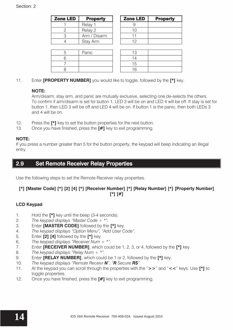
Zone LED Property Zone LED Property 1 Relay 1 9 2 Relay 2 10 3 Arm / Disarm 11 4 Stay Arm 12
5 Panic 13 6 14 7 15 8 16
11. Enter [PROPERTY NUMBER] you would like to toggle, followed by the [*] key.
NOTE: Arm/disarm, stay arm, and panic are mutually exclusive, selecting one de-selects the others. To confirm if arm/disarm is set for button 1, LED 3 will be on and LED 4 will be off. If stay is set for button 1, then LED 3 will be off and LED 4 will be on. If button 1 is the panic, then both LEDs 3 and 4 will be on.
12. Press the [*] key to set the button properties for the next button. 13. Once you have finished, press the [#] key to exit programming. NOTE: If you press a number greater than 5 for the button property, the keypad will beep indicating an illegal entry.
2.9 Set Remote Receiver Relay Properties
Use the following steps to set the Remote Receiver relay properties.
[*] [Master Code] [*] [2] [4] [*] [Receiver Number] [*] [Relay Number] [*] [Property Number] [*] [#]
LCD Keypad 1. Hold the [*] key until the beep (3-4 seconds). 2. The keypad displays “Master Code + *”. 3. Enter [MASTER CODE] followed by the [*] key. 4. The keypad displays “Option Menu”, “Add User Code”. 5. Enter [2] [4] followed by the [*] key. 6. The keypad displays “Receiver Num + *”. 7. Enter [RECEIVER NUMBER], which could be 1, 2, 3, or 4, followed by the [*] key. 8. The keypad displays “Relay Num + *”. 9. Enter [RELAY NUMBER], which could be 1 or 2, followed by the [*] key. 10. The keypad displays “Remote Receivr N”, “R Secure RS”. 11. At the keypad you can scroll through the properties with the “>>” and “<<” keys. Use [*] to
toggle properties. 12. Once you have finished, press the [#] key to exit programming.

Section: 2
IDS X64 Remote Receiver 700-408-02A Issued August 2010 15
LED Keypad 1. Hold the [*] key until the beep (3-4 seconds). 2. The READY and ARM LEDs flash alternately. 3. Enter [MASTER CODE] followed by the [*] key. 4. The READY LED flashes. 5. Enter [2] [4] followed by the [*] key. 6. The READY and ARM LEDs flash simultaneously. 7. Enter [RECEIVER NUMBER], which could be 1, 2, 3, or 4, followed by the [*] key. 8. The READY and AWAY LEDs flash simultaneously, and the ARM LED is on. 9. Enter [RELAY NUMBER] followed by the [*] key. 10. The READY LED is on if you are viewing relay 1, and the ARM LED is on if you are viewing relay 2.
Zone LED Property Zone LED Property 1 Secure 9 2 Panic 10 3 Retrigger 11 4 Pulse 12
5 13 6 14 7 15 8 16
11. Enter [PROPERTY NUMBER] which could be 1, 2, 3, or 4, followed by the [*] key. 12. Press the [*] key to scroll to next relay. 13. Once you have finished, press the [#] key to exit programming. NOTE:
If the Remote Receiver relays are configured as "secure", the effective terminals for "NC" (Normally Closed) and "NO" (Normally Open) will be swapped.
If retrigger is not enabled, the user will have to wait 30 seconds before they can press a button again. If retrigger is enabled, then the user will only have to wait 3 seconds.
2.10 Set Remote Receiver Relay Pulse Time
Use the following steps to set the Remote Receiver relay pulse time.
[*] [Master Code] [*] [2] [5] [Receiver Number] [*] [Relay Pulse Time] [*] [#] LCD Keypad 1. Hold the [*] key until the beep (3-4 seconds). 2. The keypad displays “Master Code + *”. 3. Enter [MASTER CODE] followed by the [*] key. 4. The keypad displays “Option Menu”, “Add User Code”. 5. Enter [2] [5] followed by the [*] key. 6. The keypad displays “Receiver Num + *”. 7. Enter [RECEIVER NUMBER], which could be 1, 2, 3, or 4, followed by the [*] key.

Section: 2
IDS X64 Remote Receiver 700-408-02A Issued August 2010 16
8. The keypad displays “Remote Receivr N”, “R MM:SS”. 9. Enter [RELAY PULSE TIME] followed by the [*] key. 10. The keypad displays “R time”. 11. Once you have finished, press the [#] key to exit programming. LED Keypad 1. Hold the [*] key until the beep (3-4 seconds). 2. The READY and ARM LEDs flash alternately. 3. Enter [MASTER CODE] followed by the [*] key. 4. The READY LED flashes. 5. Enter [2] [5] followed by the [*] key. 6. The READY and ARM LEDs flash simultaneously. 7. Enter [RECEIVER NUMBER], which could be 1, 2, 3, or 4, followed by the [*] key. 8. The READY LED comes on.
Time is displayed in BCD format, but is entered as 4 consecutive digits as per usual. There are four zone LEDs for every digit:
Zone LED Time Zone LED Time 1 (x 1 = 1) 9 (x 1 = 0) 2 (x 2 = 0) 10 (x 2 = 2) 3 (x 4 = 4) 11 (x 4 = 4) Mm:Ss 4 (x 8 = 0) 12 (x 8 = 0) = 45:36
5 (x 1 = 0) 13 (x 1 = 1) M = LEDs 8 through 5 6 (x 2 = 0) 14 (x 2 = 2) m = LEDs 4 through 1 7 (x 4 = 4) 15 (x 4 = 0) S = LEDs 16 through 13 8 (x 8 = 0) 16 (x 8 = 0) s = LEDs 12 through 9
EXAMPLE: To get your first minute you add up the values of LEDs 8-5. From the Table above, you will see that LED 7 is on – giving you an answer of 4. For your second minute, look at the values for LEDs 4-1. LEDs 1 and 3 are on which is a combined value of 5. For the first second we will look at LEDs 16-13. LEDs 13+14 are on, which equals 3. For our last second look at LEDs 9 through 12. The added values of LEDs 10+11 is 6. Add this all together and we get 45:36 as our time.
9. Enter [RELAY PULSE TIME], which is MMSS, followed by the [*] key. 10. The READY LED is on if viewing relay 1, and the ARM LED is on if viewing relay 2. 11. Once you have finished, press the [#] key to exit programming.
2.11 Defaulting the Remote Receiver
Use the following steps to default the Remote Receiver.
[*] [Master Code] [*] [2] [6] [*] [Receiver Number] [*] [*] [#]
LCD Keypad 1. Hold the [*] key until the beep (3-4 seconds). 2. The keypad displays “Master Code + *”. 3. Enter [MASTER CODE] followed by the [*] key. 4. The keypad displays “Option Menu”, “Add User Code”.

Section: 2
IDS X64 Remote Receiver 700-408-02A Issued August 2010 17
5. Enter [2] [6] followed by the [*] key. 6. The keypad displays “Receiver Num + *”. 7. Enter [RECEIVER NUMBER], which could be 1, 2, 3, or 4, followed by the [*] key. 8. The keypad displays “Remote Receivr N”, “Confirm with *”. 9. Press the [*] key. 10. The keypad displays “Receiver Num + *”, “Defaulted Rx N”. 11. To default additional receivers, repeat steps 7-10. 12. Once you have finished, press the [#] key to exit programming. NOTE: The keypad will beep 3 times and then repeat the beeps if the receiver is not registered. LED Keypad 1. Hold the [*] key until the beep (3-4 seconds). 2. The READY and ARM LEDs flash alternately. 3. Enter [MASTER CODE] followed by the [*] key. 4. The READY LED flashes. 5. Enter [2] [6] followed by the [*] key. 6. The READY and ARM LEDs flash simultaneously. 7. Enter [RECEIVER NUMBER], which could be 1, 2, 3, or 4, followed by the [*] key. 8. The READY and AWAY LEDs flash simultaneously, and the ARM LED is on. 9. Press the [*] key. 10. The ARM and AWAY LEDs flash simultaneously, and the READY and POWER LEDs flash
simultaneously. 11. To default additional receivers, repeat step 7. 12. Once you have finished, press the [#] key to exit programming. NOTE: Remote Receiver 1 is indicated by zone LED 1 coming on. Remote Receiver 2 is indicated by zone LED 2 coming on. Remote Receiver 3 in indicated by zone LEDs 1 +2 coming on. Remote Receiver 4 is indicated by zone LED 3 coming on.
2.12 Identify Remote Receiver
Use the following steps to identify the Remote Receiver. NOTE: Once registered, the Remote Receiver should respond to panel commands. To check, send the "Identify" command to the Remote Receiver, and verify that both Remote Receiver LEDs flash. This command may also be used to find or verify the number of a Remote Receiver, but is only useful when the Remote Receiver cover is off.
[*] [Master Code] [*] [2] [7] [*] [Receiver Number] [*] [#] LCD Keypad 1. Hold the [*] key until the beep (3-4 seconds). 2. The keypad displays “Master Code + *”. 3. Enter [MASTER CODE] followed by the [*] key. 4. The keypad displays “Option Menu”, “Add User Code”.

Section: 2
IDS X64 Remote Receiver 700-408-02A Issued August 2010 18
5. Enter [2] [7] followed by the [*] key. 6. The keypad displays “Receiver Num + *”. 7. Enter [RECEIVER NUMBER], which could be 1, 2, 3, or 4, followed by the [*] key. 8. The keypad displays “Receiver Num + *”, Identifying Rx N”.
NOTE: The keypad will beep 3 times and then repeat the beeps if the receiver is not registered. The receiver will flash both its green and red LEDs in sync. The LEDs will be pulsed on for 200ms, and then off for 200ms. This will be repeated 50 times resulting in the receiver doing an identity flash for the duration of 20 seconds.
9. To identify more receivers repeat steps 7 and 8. 10. Once you have finished, press the [#] key to exit programming. LED Keypad 1. Hold the [*] key until the beep (3-4 seconds). 2. The READY and ARM LEDs flash alternately. 3. Enter [MASTER CODE] followed by the [*] key. 4. The READY LED flashes. 5. Enter [2] [7] followed by the [*] key. 6. The READY and ARM LEDs flash simultaneously. 7. Enter [RECEIVER NUMBER], which could be 1, 2, 3, or 4, followed by the [*] key. 8. The ARM and AWAY LEDs flash simultaneously, and the READY and POWER LEDs flash
simultaneously. NOTE: The keypad will beep 3 times and then repeat the beeps if the receiver is not registered. The receiver will flash both its green and red LEDs in sync. The LEDs will be pulsed on for 200ms, and then off for 200ms. This will be repeated 50 times resulting in the receiver doing an identity flash for the duration of 20 seconds.
9. To identify more receivers repeat step 7. 10. Once you have finished, press the [#] key to exit programming. NOTE: Remote Receiver 1 is indicated by zone LED 1 coming on. Remote Receiver 2 is indicated by zone LED 2 coming on. Remote Receiver 3 in indicated by zone LEDs 1 +2 coming on. Remote Receiver 4 is indicated by zone LED 3 coming on.
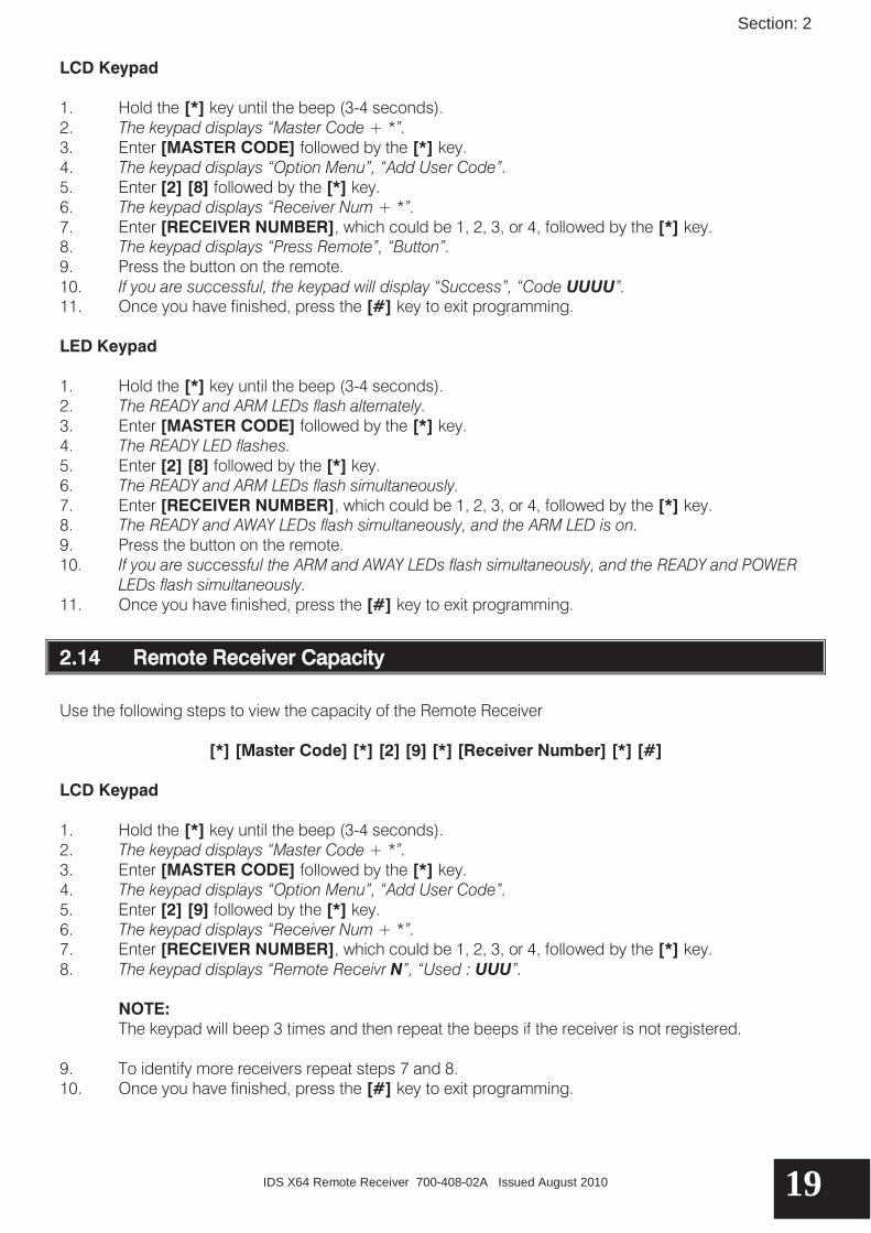
2.13 Remote Receiver Test
Use the following steps to test the remote receiver. NOTE: This command puts the Remote Receiver into test mode for a few minutes. While in test mode, the X64 Alarm Panel ignores buttons pressed on known Remote Transmitters, and the keypad displays their user codes.
[*] [Master Code] [*] [2] [8] [*] [Receiver Number] [*] [#]
Section: 2
IDS X64 Remote Receiver 700-408-02A Issued August 2010 19
LCD Keypad 1. Hold the [*] key until the beep (3-4 seconds). 2. The keypad displays “Master Code + *”. 3. Enter [MASTER CODE] followed by the [*] key. 4. The keypad displays “Option Menu”, “Add User Code”. 5. Enter [2] [8] followed by the [*] key. 6. The keypad displays “Receiver Num + *”. 7. Enter [RECEIVER NUMBER], which could be 1, 2, 3, or 4, followed by the [*] key. 8. The keypad displays “Press Remote”, “Button”. 9. Press the button on the remote. 10. If you are successful, the keypad will display “Success”, “Code UUUU”. 11. Once you have finished, press the [#] key to exit programming. LED Keypad 1. Hold the [*] key until the beep (3-4 seconds). 2. The READY and ARM LEDs flash alternately. 3. Enter [MASTER CODE] followed by the [*] key. 4. The READY LED flashes. 5. Enter [2] [8] followed by the [*] key. 6. The READY and ARM LEDs flash simultaneously. 7. Enter [RECEIVER NUMBER], which could be 1, 2, 3, or 4, followed by the [*] key. 8. The READY and AWAY LEDs flash simultaneously, and the ARM LED is on. 9. Press the button on the remote. 10. If you are successful the ARM and AWAY LEDs flash simultaneously, and the READY and POWER
LEDs flash simultaneously. 11. Once you have finished, press the [#] key to exit programming.
2.14 Remote Receiver Capacity
Use the following steps to view the capacity of the Remote Receiver
[*] [Master Code] [*] [2] [9] [*] [Receiver Number] [*] [#] LCD Keypad 1. Hold the [*] key until the beep (3-4 seconds). 2. The keypad displays “Master Code + *”. 3. Enter [MASTER CODE] followed by the [*] key. 4. The keypad displays “Option Menu”, “Add User Code”. 5. Enter [2] [9] followed by the [*] key. 6. The keypad displays “Receiver Num + *”. 7. Enter [RECEIVER NUMBER], which could be 1, 2, 3, or 4, followed by the [*] key. 8. The keypad displays “Remote Receivr N”, “Used : UUU”.
NOTE: The keypad will beep 3 times and then repeat the beeps if the receiver is not registered.
9. To identify more receivers repeat steps 7 and 8. 10. Once you have finished, press the [#] key to exit programming.
Section: 2
IDS X64 Remote Receiver 700-408-02A Issued August 2010 20
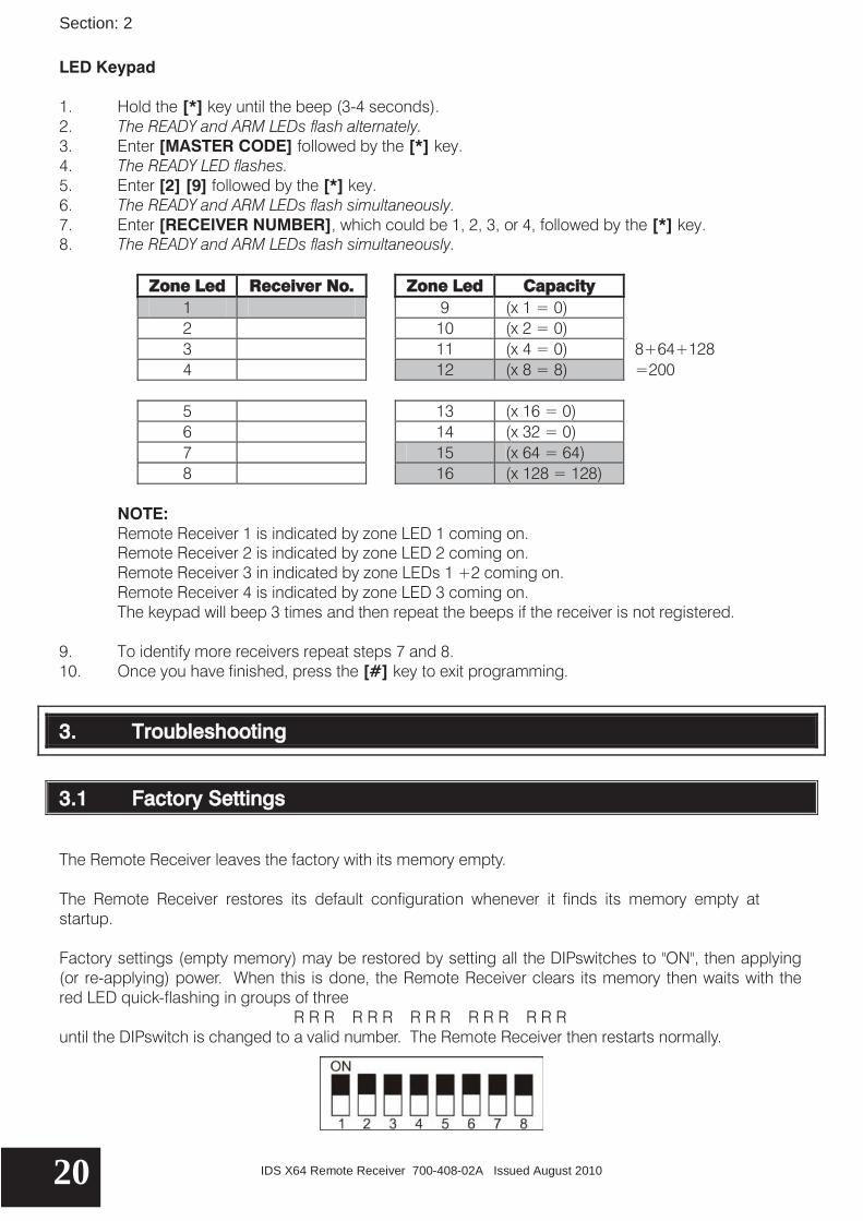
LED Keypad 1. Hold the [*] key until the beep (3-4 seconds). 2. The READY and ARM LEDs flash alternately. 3. Enter [MASTER CODE] followed by the [*] key. 4. The READY LED flashes. 5. Enter [2] [9] followed by the [*] key. 6. The READY and ARM LEDs flash simultaneously. 7. Enter [RECEIVER NUMBER], which could be 1, 2, 3, or 4, followed by the [*] key. 8. The READY and ARM LEDs flash simultaneously.
Zone Led Receiver No. Zone Led Capacity
1 9 (x 1 = 0) 2 10 (x 2 = 0) 3 11 (x 4 = 0) 8+64+128 4 12 (x 8 = 8) =200 5 13 (x 16 = 0) 6 14 (x 32 = 0) 7 15 (x 64 = 64) 8 16 (x 128 = 128)
NOTE: Remote Receiver 1 is indicated by zone LED 1 coming on. Remote Receiver 2 is indicated by zone LED 2 coming on. Remote Receiver 3 in indicated by zone LEDs 1 +2 coming on. Remote Receiver 4 is indicated by zone LED 3 coming on. The keypad will beep 3 times and then repeat the beeps if the receiver is not registered.
9. To identify more receivers repeat steps 7 and 8. 10. Once you have finished, press the [#] key to exit programming.
3. Troubleshooting
3.1 Factory Settings
The Remote Receiver leaves the factory with its memory empty. The Remote Receiver restores its default configuration whenever it finds its memory empty at startup. Factory settings (empty memory) may be restored by setting all the DIPswitches to "ON", then applying (or re-applying) power. When this is done, the Remote Receiver clears its memory then waits with the red LED quick-flashing in groups of three
R R R R R R R R R R R R R R R until the DIPswitch is changed to a valid number. The Remote Receiver then restarts normally.
Section: 3
IDS X64 Remote Receiver 700-408-02A Issued August 2010 21
3.2 Warnings
All known Remote Transmitters send the same set of button codes, but the button position for a given button code varies between manufacturers. NOTE: If Remote Transmitters of various types are used on a system, a person operating someone else's Remote Transmitter might get unexpected results. It is therefore recommended that all Remote Transmitters used on a system be identical. Remote Receivers in a system could be configured with different default button actions. But, it is possible that two Remote Receivers will receive the same Remote Transmitter signal and send its action to the panel, and if the Remote Receivers' default button actions are different they may well conflict or confuse the panel. It is therefore recommended that all Remote Receivers in any system be configured with identical default button actions.
3.3 Registration
After successful startup, the amber LED lights up whenever the X64 Bus is available. If it is not lit, and the panel is not in installer mode, then check both continuity and polarity of the data Bus wiring. After startup, the DIPswitches are ignored. Upon completion of startup, including assignment of a valid Remote Receiver number, the LEDs flash RED group 2
RR RR RR RR RR RR RR RR and the Remote Receiver waits until the Bus is available, and then requests registration. The delay before requesting registration depends on the Remote Receiver number, and traffic on the Bus. It may vary from an instant to a minute or two, or even more if the panel is in installer mode. Successful registration is indicated by LEDs flashing GREEN (standby mode)
GGGG GGGG GGGG GGGG GGGG
3.5 Startup
When the Remote Receiver starts or restarts, it flashes its LEDs in a pattern which indicates the software version. For each digit, the GREEN LED defines the digit display time, while the RED LED flashes "digit" times. The decimal is indicated by both LEDs flashing quickly. For example, version 2.03 would be displayed as: GGGGGGGGGGGGG G G G G GGGGGGG GGGGGGGGGGGGGGGGGGG RRR RRR R R R R RRR RRR RRR 2 decimal 0 3 The DIPswitch is debounced while the version is flashing, and is read when flashing is complete.

IDS X64 Remote Receiver 700-408-02A Issued August 2010 22

IDS X64 Remote Receiver 700-408-02A Issued August 2010 23

IDS X64 Remote Receiver 700-408-02A Issued August 2010 24