Embed Size (px)
Citation preview

White Paper
Identifying Sources of External PIM

2
Background:Passive intermodulation (PIM) is a well-known problem in cellular systems. Downlink signals at the cell site mix at passive, non-linear junctions in the RF path, creating new signals. If these new signals (intermodulation products) fall in an operator’s uplink band, they can elevate the noise floor and degrade system performance.
Factory PIM test equipment has been commercially available for over 20 years. RF equipment manufacturers use this equipment to verify that the components they produce are low PIM. Third order intermodulation product (IM3) levels below –107 dBm (–150 dBc) when tested using 2x 43 dBm (20 W) test signals are commonly achieved. Field PIM test equipment was introduced approximately a decade later and is used to ensure that the completed cell site is low PIM. The field test not only verifies the condition of the RF components but also verifies that the installation crew applied proper workmanship techniques while assembling the site. IM3 levels below –100 dBm (–143 dBc) are often specified and achieved.
Even with low PIM components and perfect installation techniques a site can still exhibit very poor PIM performance due to PIM sources located beyond the antenna. In these instances, signals emitting from the antenna excite non-linear objects in the main beam of the antenna as well as non-linear objects in any direction within a few wavelengths of the antenna. These non-linear objects radiate or directly couple IM products back into the antenna system at surprisingly high levels. It is not uncommon for external PIM sources to generate IM3 as high as –50 dBm (–93 dBc) when measured at the system receiver!
External PIM is typically caused by loose metal-to-metal contacts. Some of these PIM sources are relatively easy to identify:
• Airhandlingequipmentontherooftop• Overlappinglayersofmetalflashing• Sheetmetalcabletrays• Sheetmetalroofvents• Rustymetalobjects
OtherexternalPIMsourcesarenotsoobvious:
• Loosemetal-to-metalconnectionshiddenfrom view by roofing materials
• Loosecablehangersbehindtheantenna
In2010Anritsuannounced,thatithadinventedandsucceededindevelopingapatentedtechnologythat pinpoints PIM faults called Distance-to-PIM™ (DTP). DTP shows the location for PIM problems within the antenna system, as well as distance to external PIM sources outside the antenna system. This was an incredible step forward in improving the quality of information received from the on-site PIM test. But one problem still remained for pinpointing external PIM beyond the antenna, DTP could tell you how far away from the antenna the PIM source was located, but not the angle. If the antenna had a 120° beamwidth, the PIM could be located anywhere along the 120° arc at the distance measured by DTP.
In addition, depending on the site configuration, there can be multiple PIM sources simultaneously in play, both in front of and behind the antenna. This is often the case on rooftop sites where the antennas are recessed from the edge of the building or hidden behind concealment panels to improve site aesthetics.
3
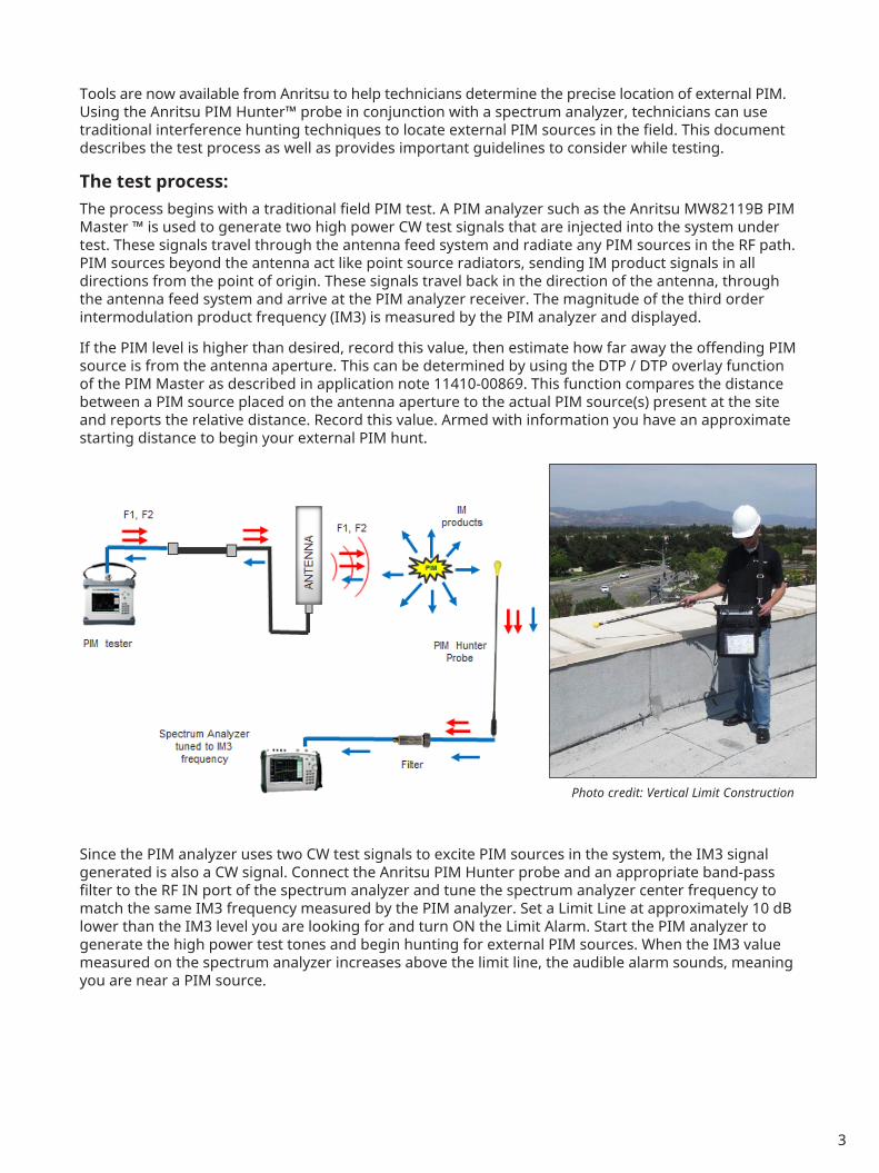
ToolsarenowavailablefromAnritsutohelptechniciansdeterminethepreciselocationofexternalPIM.UsingtheAnritsuPIMHunter™probeinconjunctionwithaspectrumanalyzer,technicianscanusetraditional interference hunting techniques to locate external PIM sources in the field. This document describes the test process as well as provides important guidelines to consider while testing.
The test process:TheprocessbeginswithatraditionalfieldPIMtest.APIManalyzersuchastheAnritsuMW82119BPIMMaster ™ is used to generate two high power CW test signals that are injected into the system under test. These signals travel through the antenna feed system and radiate any PIM sources in the RF path. PIM sources beyond the antenna act like point source radiators, sending IM product signals in all directions from the point of origin. These signals travel back in the direction of the antenna, through theantennafeedsystemandarriveatthePIManalyzerreceiver.Themagnitudeofthethirdorderintermodulationproductfrequency(IM3)ismeasuredbythePIManalyzeranddisplayed.
If the PIM level is higher than desired, record this value, then estimate how far away the offending PIM source is from the antenna aperture. This can be determined by using the DTP / DTP overlay function ofthePIMMasterasdescribedinapplicationnote11410-00869.Thisfunctioncomparesthedistancebetween a PIM source placed on the antenna aperture to the actual PIM source(s) present at the site andreportstherelativedistance.Recordthisvalue.Armedwithinformationyouhaveanapproximatestarting distance to begin your external PIM hunt.
SincethePIManalyzerusestwoCWtestsignalstoexcitePIMsourcesinthesystem,theIM3signalgeneratedisalsoaCWsignal.ConnecttheAnritsuPIMHunterprobeandanappropriateband-passfiltertotheRFINportofthespectrumanalyzerandtunethespectrumanalyzercenterfrequencytomatchthesameIM3frequencymeasuredbythePIManalyzer.SetaLimitLineatapproximately10dBlowerthantheIM3levelyouarelookingforandturnONtheLimitAlarm.StartthePIManalyzertogenerate the high power test tones and begin hunting for external PIM sources. When the IM3 value measuredonthespectrumanalyzerincreasesabovethelimitline,theaudiblealarmsounds,meaningyou are near a PIM source.
Photo credit: Vertical Limit Construction

4
Asshowninthefigureabove,whentheprobetipcomesincloseproximitytoaPIMsource,theIM3valuemeasuredonthespectrumanalyzerincreasesrapidly.WhentheprobetipismovedbeyondthePIM source, the IM3 level decreases rapidly. The change in IM3 value is typically 10 dB within 150 mm (6inches)fromthePIMsource.Movetheprobetipbackandforthintheareaofinterestuntilthemaximum signal location is identified. Mark these spots with highly visible tape and continue hunting. Continue probing the field until all significant external PIM sources have been identified.
It is not uncommon for high signal variation to occur when the probe tip is far away from PIM sources. This is due to multipath fading of the IM3 signal from multiple PIM sources or from reflective surfaces atthesite.OnceclosetoaPIMsource,thesignalfromthatPIMsourcebecomesdominant,reducingsignal level variation.
Important considerations:Safety: Care must be taken while hunting for external PIM sources to ensure that technicians performing the test are not exposed to RF fields in excess of the local jurisdiction’s maximum allowable occupational exposure limit. In the United States, the Federal Communications Commission (FCC) occupational / controlledexposurelimitsbetween300MHzand10GHzareshowninthetablebelow.Asawirelessprofessional working near antennas, it is important to know your local exposure requirements and maintain safe working distances. Safe working distances can be calculated for various site configurations using the equations provided below.
Frequency Occupational/ControlledExposure (mW/cm2)
300MHzto1500MHz F(MHz)/300
1500MHzto100,000MHz 5
150 mm (6 inch)
IM3 signal level vs. Distance from an external PIM source

5
Calculations / Conversions:EIRPdBm=Testpower(dBm)+3dB+Antennagain(dBi)–Directionadjustment(dB)–Cableloss(dB)(3 dB is added above because two high power test tones are present)EIRPW = (10^ ( EIRPdBm / 10) / 1000 )MPE (W/m2) = MPE (mW/cm2) * 10SafeDistance=SQRT(EIRPW/(4π*MPE (W/m2) ) )
Definitions:EIRPdBm = Effective Isotropic Radiated Power in dBmEIRPW = Effective Isotropic Radiated Power in WattsMPE (W/m2) = Maximum Permissible Exposure in W/m2
MPE (mW/cm2) = Maximum Permissible Exposure in mW/cm2
Direction adjustment = Front-to-Side ratio or Front-to-Back ratio based on the antenna patternSafe Distance = Distance from antenna where MPE is achieved
Using the FCC limits and assuming test cable loss = 0.5 dB, Front-to-side ratio = 15 dB and Front-to-backratio=25dBfor65°PanelAntenna,thefollowingsafeworkingdistancescanbecalculated:
Antennatype Frequency Gain(dBi) Test power (dBm)
Distance (front)
Distance (side)
Distance (rear)
65°PanelAntenna 700–900MHz 15.5 43 2.0 m 0.4 m 0.1 m
65°PanelAntenna 1700–2100MHz 17.5 43 1.8m 0.3 m 0.1 m
OmniAntenna 700–900MHz 12.0 43 1.3 m N/A N/A
OmniAntenna 1700–2100MHz 12.0 43 0.9 m N/A N/ASmallOmniAntenna 700–900MHz 3.5 37 0.3 m N/A N/A
SmallOmniAntenna 1700–2100MHz 5.0 37 0.2 m N/A N/A
Clearly it is important to be aware of these safe working distances while hunting for external PIM. The PIMHunterprobeisapproximately1minlength,allowingyoutoprobelocationsnearantennaswhileremaining in compliance with occupational exposure limits. If it becomes necessary to probe areas close to the front of an antenna, do so with your body behind or beside the antenna.
Band-pass filters: OneoftheworstPIMsourcesatthecellsiteisthereceiveronyourspectrumanalyzer!If the high power test tones used to excite external PIM sources are able to reach the receiver front end, extremelyhighPIMlevelswillbegeneratedwithinthespectrumanalyzeritself.Topreventthis,ahighqualitybandpassfiltermustbeinstalledbetweenthePIMHunterprobeandtheinputportofthespectrumanalyzer.ThisfiltermustallowtheIM3signal of interest to pass while attenuating the two high power test signals generated bythePIManalyzer.ThesamefiltersavailableforusewiththeAnritsuMA2700AInterferenceHunter™workwellforthisapplication. See Technical Datasheet 11410-00719 for available filters.
Band-pass filter with plastic case removed

6
Spectrum Analyzer Settings:ThespectrumanalyzersettingsbelowprovideagoodstartingpointforanexternalPIMhunt.Refertoyourspectrumanalyzeruserguideforinstructionsforsettingthefollowingparameters.
• Centerfrequency=IM3frequencyfromPIManalyzer• Span=100kHz• Amplitudereferencelevel=20dBhigherthanpeakIM3measuredonPIMMaster• Scale=10dB/div• AutoAtten=ON• AutoRBW=ON• AutoVBW=ON• Pre-amp=ON• TraceAOperations=Average–>A• #ofaverages=2• TraceBOperations=Maxhold–>B• SweepMode=BurstDetect• UpperLimit=ON• Limitlevel=10dBlowerthanpeakIM3measuredonPIMMaster• LimitAlarm=ON• Volume=settomaximum(foundinthesystemmenu)
TheMW82119BPIMMasterpulsestheCWPIMtestsignalsonandoffcontinuouslyduringthePIMtesttoreducebatteryconsumption.Asaresult,theIM3signalyouarehuntingisalsoapulsedsignal.Aspectrumanalyzerequippedwithburstdetect,suchastheMS2720T,isrecommendedtoeffectivelycapturethepulsingIM3signal.Averaging2or3sweepssmoothstheresultingmagnitudewhilemaintaining quick response to changes in PIM level.
Inmostcases,theIM3signalyouareseekingwillberelativelyhighlevelsignal(–50dBmto–80dBm).Withtheabovesettings,thenoisefloorofthespectrumanalyzershouldbewellbelow–100dBm.AssoonasthePIMAnalyzeristurnedon,theIM3signalshouldappearonthespectrumanalyzer.WhenthePIMHunterprobetipislocatedclosetothePIMsource,thelevelwillincreaserapidly.
Usethelimitalarmfeatureofthespectrumanalyzertoprovideanaudiblealarmonlywhentheprobetipis near a PIM source. This allows the operator “listen for PIM sources” rather than having to constantly focusonthespectrumanalyzerdisplay.Adjustthelimitlevelupordownasrequiredtoonlygeneratetones when the probe tip is within 0.25 meter of significant PIM sources.
IM3 level seen when away from a PIM source IM3 level seen when near a PIM source

7
Max hold on the B trace is useful for comparing the maximum IM3 level detected to the current IM3 level. If an audible alarm is heard while scanning across an area, slow down and scan the area more slowlylookingforthelocationwherethemaximumoccurred.OnceaPIMsourcelocationisidentifiedand marked, use the Reset Trace function to reset the maximum trace before hunting the next PIM source.
Be conscious of where you are standing:Asitturnsout,yourbodyisaprettygoodattenuator.IfyoustandbetweentheantennaandaPIMsource,thePIMlevelmayreduceby>30dB.Whileprobing,beconsciousofwheretheantennaislocatedandmakesurethePIMHunterprobetipisnotbeing“shadowed” by your body.
PIM is always high directly in front of the antenna: When probing screening walls or metal objects less than 1 wavelength in front of an antenna the CW test signals entering the probe will be significantly higher. Even with a high quality bandpass filter, the test tone levels may not be attenuated enough to preventfalsePIMreadings.Increasingtheattenuationlevelonthespectrumanalyzerand/orreducingthetestpowerlevelonthePIManalyzermayimproveresultswhentestingnearthefaceoftheantenna.
PIM seems to be coming from everywhere: The external PIM hunting process works well if the PIM sources are truly external. If, however, the dominant PIM source is inside the antenna system, the antenna will spray the IM3 frequency into the environment. The radiated IM3 signal will bounce off of metal object in front of the antenna, causing just about everything to look like a PIM generator. In somecases,justholdingthePIMHunterprobeintheairwillgenerateahighPIMresult.Withexperience,youwilllearntorecognizethiseffectandfocusyouattentionbacktotheantennaratherthan the environment..
PIM levels change dramatically and I am not moving the probe: Atanygivenmoment,thePIMHuntersystem is detecting the vector sum of all PIM sources arriving at the probe tip. In some cases, there may be highly variable PIM source somewhere on the sector that is extremely sensitive to mechanical movement. Shifting your weight may cause a PIM source 3 meters away to increase in magnitude by 40dB!ThePIMHunterprobewilldetectthisincrease,eveniftheprobeisnotdirectlyoverthesource.Try standing as still as possible while moving the probe around to see if the signal level changes. For this same reason, it is highly recommended that only one person be moving on the rooftop at a time while the PIM hunt is in progress.
AnotherthingtokeepinmindisthattheIM3frequencyyouaremeasuringmayalsobeinusebymobiles attempting to communicate with the cell site. If you see short, bursty signals that raise the noiseflooracrossthefull100kHzbandwidthofthedisplay,youarelikelyseeinglivetraffic.Ifthesignallevelfrommobilespersists,changeyourtestsettingsonboththePIManalyzerandthespectrumanalyzertomovetheIM3frequencytounusedspectrum.
Correct Not Correct

8
Correcting the PIM problems after identificationIn some cases, external PIM sources can be easily repaired on the first PIM hunting visit to a site. Examples might include removing rust and applying a fresh coat of paint to steel objects, tightening mounting hardware or wrapping metal objects in RF absorbing foam to attenuate the PIM.
Inothercases,morecomplexrepairsmightberequiredthatcannotberesolvedinasinglevisit.Atypicalexample might be unseen metal-to-metal contacts below the roofing material surface that need repair. In these situations, it is desirable to clearly document the areas of concern and deploy temporary “fixes” to determine the performance benefits that could be gained by a permanent repair. Temporary fixes in use today include deploying PIM Blankets or RF absorbing foam over the PIM sources identified during the PIM hunt. PIM Blankets are available from manufactures such as ConcealFab Corp. (www.concealfab.com) and RF absorbing foam is available from manufactures such as Cuming Microwave (www.cumingmicrowave.com).
PIM Blankets deployed over large area generating PIM RF absorber placed over small area generating PIM
PIM reduced 15 dB by tightening hardware below the antenna

9
ThePIManalyzerservesmultiplepurposesintheexternalPIMidentificationandremediationprocess.ItfirstactsasthehighpowersignalsourceenablingthePIMHuntertopreciselyidentifyexternalPIMlocations. It also performs the pass / fail measurement necessary to document whether or not fixes, both permanent as well as temporary, will meet system requirements.
Conclusion:Identifying the location of external PIM sources has been an extremely difficult problem for mobile operatorsworldwide.WithAnritsu’sPIMHunter™,PIMMaster™andSpectrumMaster™products,operatorsfinallyhavethetoolsetrequiredtopreciselyidentifyexternalPIMsources.Onceidentified,avariety of PIM mitigation techniques can be deployed to reduce PIM levels and improve system performance.
PIM level before deploying temporary fix
PIM level able to be achieved with temporary fix deployed (30 dB reduction)

11410-00992,Rev.A PrintedinUnitedStates 2016-11©2016AnritsuCompany.AllRightsReserved.
®Anritsu Alltrademarksareregisteredtrademarksoftheirrespectivecompanies.Datasubjecttochangewithout notice.For the most recent specifications visit: www.anritsu.com
• United States Anritsu Company1155 East Collins Boulevard, Suite 100, Richardson,TX,75081U.S.A. TollFree:1-800-267-4878 Phone:+1-972-644-1777 Fax:+1-972-671-1877
• Canada Anritsu Electronics Ltd.700 Silver Seven Road, Suite 120, Kanata,OntarioK2V1C3,Canada Phone:+1-613-591-2003 Fax:+1-613-591-1006
• Brazil Anritsu Electrônica Ltda.PraçaAmadeuAmaral,27-1Andar 01327-010-BelaVista-SaoPaulo-SP-Brazil Phone:+55-11-3283-2511 Fax:+55-11-3288-6940
• Mexico Anritsu Company, S.A. de C.V.Av.EjércitoNacionalNo.579Piso9,Col.Granada 11520México,D.F.,México Phone: +52-55-1101-2370 Fax: +52-55-5254-3147
• United Kingdom Anritsu EMEA Ltd.200CapabilityGreen,Luton,BedfordshireLU13LU,U.K. Phone:+44-1582-433280 Fax:+44-1582-731303
• France Anritsu S.A.12avenueduQuébec,BatimentIris1-Silic612, 91140Villebon-sur-Yvette,France Phone:+33-1-60-92-15-50 Fax:+33-1-64-46-10-65
• Germany Anritsu GmbHNemetschekHaus,Konrad-Zuse-Platz1 81829München,Germany Phone:+49-89-442308-0 Fax:+49-89-442308-55
• Italy Anritsu S.r.l.ViaElioVittorini129,00144RomaItaly Phone:+39-06-509-9711 Fax:+39-06-502-2425
• Sweden Anritsu ABKistagången20B,16440KISTA,Sweden Phone:+46-8-534-707-00 Fax:+46-8-534-707-30
• Finland Anritsu ABTeknobulevardi3-5,FI-01530VANTAA,Finland Phone:+358-20-741-8100 Fax:+358-20-741-8111
• Denmark Anritsu A/SKay Fiskers Plads 9, 2300 Copenhagen S, Denmark Phone: +45-7211-2200 Fax: +45-7211-2210
• Russia Anritsu EMEA Ltd. Representation Office in RussiaTverskayastr.16/2,bld.1,7thfloor. Moscow, 125009, Russia Phone:+7-495-363-1694 Fax:+7-495-935-8962
• Spain Anritsu EMEA Ltd. Representation Office in SpainEdificioCuzcoIV,Po.delaCastellana,141,Pta.5 28046,Madrid,Spain Phone:+34-915-726-761 Fax:+34-915-726-621
• United Arab Emirates Anritsu EMEA Ltd. Dubai Liaison OfficePOBox500413-DubaiInternetCity AlThurayaBuilding,Tower1,Suite701,7thfloor Dubai,UnitedArabEmirates Phone:+971-4-3670352 Fax:+971-4-3688460
• India Anritsu India Pvt Ltd.2nd&3rdFloor,#837/1,Binnamangla1stStage, Indiranagar,100ftRoad,Bangalore-560038,India Phone:+91-80-4058-1300 Fax:+91-80-4058-1301
• Singapore Anritsu Pte. Ltd.11ChangCharnRoad,#04-01,ShriroHouse Singapore159640 Phone:+65-6282-2400 Fax:+65-6282-2533
• P. R. China (Shanghai) Anritsu (China) Co., Ltd.27thFloor,TowerA, New Caohejing International Business Center No.391GuiPingRoadShanghai,XuHuiDiDistrict, Shanghai 200233, P.R. China Phone:+86-21-6237-0898 Fax:+86-21-6237-0899
• P. R. China (Hong Kong) Anritsu Company Ltd.Unit1006-7,10/F.,GreenfieldTower,ConcordiaPlaza, No. 1 Science Museum Road, Tsim Sha Tsui East, Kowloon,HongKong,P.R.China Phone:+852-2301-4980 Fax:+852-2301-3545
• Japan Anritsu Corporation8-5,Tamura-cho,Atsugi-shi, Kanagawa,243-0016Japan Phone:+81-46-296-6509 Fax:+81-46-225-8359
• Korea Anritsu Corporation, Ltd.5FL,235Pangyoyeok-ro,Bundang-gu,Seongnam-si,Gyeonggi-do,13494Korea Phone:+82-31-696-7750 Fax:+82-31-696-7751
• Australia Anritsu Pty Ltd.Unit 20, 21-35 Ricketts Road, MountWaverley,Victoria3149,Australia Phone:+61-3-9558-8177 Fax:+61-3-9558-8255
• Taiwan Anritsu Company Inc.7F,No.316,Sec.1,NeihuRd.,Taipei114,Taiwan Phone:+886-2-8751-1816 Fax:+886-2-8751-1817
Specificationsaresubjecttochangewithoutnotice.


![AppNote - PIM - Mitigating Ext. Sources of PIM [11410-00756A]](https://img.pdfslide.us/doc/110x75/55cf9b4e550346d033a5882d/appnote-pim-mitigating-ext-sources-of-pim-11410-00756a.jpg)