Embed Size (px)
Citation preview
University of New Hampshire 121 Technology Drive, Suite 2 InterOperability Laboratory Durham, NH 03824 Routing Consortium Phone: +1-603-862-3941 http://www.iol.unh.edu Fax: +1-603-862-4181
ROUTING CONSORTIUM
Protocol Independent Multicast – Sparse Mode Interoperability Test Suite
Technical Document
Revision 1.5
© 2006 University of New Hampshire InterOperability Laboratory
University of New Hampshire InterOperability Laboratory
ROUTING CONSORTIUM 2 PIM-SM Interoperability Test Suite
MODIFICATION RECORD Version 1.5 August 27, 2008
• Removed tests 1.2d and 1.2e. Version 1.4 July 22, 2008
• Changed Test Suite to be IPv4/IPv6 Independent Version 1.3 January 11, 2008
• Removed TR2 from 2.2b and 2.4a • Revised 3.2a and 3.3a • Added 1.2d and 1.2e
Version 1.2 June 7, 2007
• Updated to RFC 4601 Version 1.1 September 14, 2006
• Removed Test2.4c Version 1.0 May 1st, 2006
University of New Hampshire InterOperability Laboratory
ROUTING CONSORTIUM 3 PIM-SM Interoperability Test Suite
ACKNOWLEDGEMENTS The University of New Hampshire would like to acknowledge the efforts of the following individuals in the development of this test suite. David Bond University of New Hampshire Chris Burke University of New Hampshire Erica Williamsen University of New Hampshire Timothy Winters University of New Hampshire
University of New Hampshire InterOperability Laboratory
ROUTING CONSORTIUM 4 PIM-SM Interoperability Test Suite
INTRODUCTION Overview The University of New Hampshire’s InterOperability Laboratory (IOL) is an institution designed to improve the interoperability of standards based products by providing an environment where a product can be tested against other implementations of a standard. This suite of tests has been developed to help implementers evaluate the functioning of their Protocol Independent Multicast – Sparse Mode implementations. The tests do not determine if a product conforms to the specifications, nor are they purely interoperability tests. Rather, they provide a method to isolate problems within a device. Successful completion of all tests contained in this suite does not guarantee that the tested device will operate with other PIM-SM devices. However, these tests provide a reasonable level of confidence that the Router Under Test will function well in most multi-vendor PIM-SM environments. Underlying Layer 3 Protocol This Test Suite can be run with either IPv4 or IPv6 as the underlying layer 3 protocol. The Test Multicast Group for IPv4 is 224.0.6.130 and for IPv6 it is FF1E::AA. The network topologies pictures are labeled for IPv4. For IPv6 replace the term network with link. For IPv4 use IGMP and for IPv6 use MLD. Acronyms TR: Testing Router RP: Rendezvous Point DR: Designated Router IGMP: Internet Group Management Protocol MLD: Multicast Listener Discovery MRIB: Multicast Routing Information Base RPF: Reverse Path Forwarding TIB: Tree Information Base MFIB: Multicast Forwarding Information Base SPT: Shortest Path Tree RPT: Rendezvous Point Tree When several entities of the same type are present in a test configuration, a number is appended to the acronym to yield a label for each entity. For example, if there were three testing routers in the test configuration, they would be labeled TR1, TR2 and TR3. Definitions Rendezvous Point (RP):
University of New Hampshire InterOperability Laboratory
ROUTING CONSORTIUM 5 PIM-SM Interoperability Test Suite
A RP is a router that has been configured to be the root of the non-source-specific distribution tree for a multicast group. Join messages from receivers for a group are sent towards the RP, and data from senders is sent to the RP so that receivers can discover who the senders are, and start to receive traffic destined for the group. Designated Router (DR): A shared-media LAN like Ethernet may have multiple PIM-SM routers connected to it. If the LAN has directly connected hosts, then a single one of these routers, the DR, will act on behalf of those hosts with respect to the PIM-SM protocol. A single DR is elected per interface (LAN or otherwise) using a simple election process. MRIB Multicast Routing Information Base: This is the multicast topology table, which is typically derived from the unicast routing table, or routing protocols such as MBGP that carry multicast-specific topology information. In PIM-SM, the MRIB is used to decide where to send Join/Prune messages. A secondary function of the MRIB is to provide routing metrics for destination addresses, these metrics are used when sending and processing Assert messages. RPF Neighbor: RPF stands for "Reverse Path Forwarding". The RPF Neighbor of a router with respect to an address is the neighbor that the MRIB indicates should be used to forward packets to that address. In the case of a PIM-SM multicast group, the RPF neighbor is the router that a Join message for that group would be directed to, in the absence of modifying Assert state. TIB Tree Information Base: This is the collection of state at a PIM Router that has been created by receiving PIM Join/Prune messages, PIM Assert messages, and IGMP or MLD information from local hosts. It essentially stores the state of all multicast distribution trees at that router. MFIB Multicast Forwarding Information Base: The TIB holds all the state that is necessary to forward multicast packets at a router. However, although this specification defines forwarding in terms of the TIB, to actually forward packets using the TIB is very inefficient. Instead a real router implementation will normally build an efficient MFIB from the TIB state to perform forwarding. How this is done is implementation-specific, and is not discussed in this document. Upstream Towards the root of the tree. The root of tree may either be the source or the RP depending on the context. Downstream Away from the root of the tree.
University of New Hampshire InterOperability Laboratory
ROUTING CONSORTIUM 6 PIM-SM Interoperability Test Suite
TIMERS AND DEFAULT VALUES PIM-SM defines several timers and default values. For the purpose of testing, all configurable timers and values are set to their defaults, unless otherwise noted in the test description. These defaults are given here for reference, taken or calculated from RFC 4601, Section 4.12: Hello_Period: 30 Seconds Triggered_Hello_Delay: 5 Seconds Holdtime: 105 Seconds Assert_Time: 180 Seconds Assert_Override_Interval: 3 Seconds Register_Suppression_Time: 60 Seconds t_override: 2.5 Seconds t_periodic: 60 Seconds
University of New Hampshire InterOperability Laboratory
ROUTING CONSORTIUM 7 PIM-SM Interoperability Test Suite
TEST ORGANIZATION This document organizes tests by group based on related test methodology or goals. Each group begins with a brief set of comments pertaining to all tests within that group. This is followed by a series of description blocks; each block describes a single test. The format of the description block is as follows: Test Label:
The test label and title comprise the first line of the test block. The test label is composed by concatenating the short test suite name, the group number, and the test number within the group, separated by periods. The Test Number is the group and test number, also separated by a period. So, test label PIM.1.2 refers to the second test of the first test group in the PIM-SM Interop suite. The test number is 1.2.
Purpose: The Purpose is a short statement describing what the test attempts to achieve. It is usually phrased as a simple assertion of the feature or capability to be tested.
References: The References section lists cross-references to the specifications and documentation that might be helpful in understanding and evaluating the test and results.
Discussion: The Discussion is a general discussion of the test and relevant section of the specification, including any assumptions made in the design or implementation of the test as well as known limitations.
Test Setup: The Test Setup section describes the configuration of all devices prior to the start of the test. Different parts of the procedure may involve configuration steps that deviate from what is given in the test setup. If a value is not provided for a protocol parameter, then the protocol’s default is used for that parameter.
Procedure: This section of the test description contains the step-by-step instructions for carrying out the test. These steps include such things as enabling interfaces, unplugging devices from the network, or transmitting packet from a test station. The test procedure also cues the tester to make observations, which are interpreted in accordance with the observable results given for that test part.
Observable Results:
This section lists observable results that can be examined by the tester to verify that the TR is operating properly. When multiple observable results are possible, this section provides a short discussion on how to interpret them. The determination of a pass or fail for each test is usually based on how the TR’s behavior compares to the results described in this section.
Possible Problems: This section contains a description of known issues with the test procedure, which may affect test results in certain situations.
University of New Hampshire InterOperability Laboratory
ROUTING CONSORTIUM 8 PIM-SM Interoperability Test Suite
REFERENCES The following documents are referenced in this text:
• Request for Comments 4601 – Protocol Independent Multicast - Sparse Mode (PIM-SM): Protocol Specification (Revised)
• Request for Comments 2236 − Internet Group Management Protocol, Version 2 • Request for Comments 3810 − Multicast Listener Discovery Version 2 (MLDv2) for IPv6
University of New Hampshire InterOperability Laboratory
ROUTING CONSORTIUM 9 PIM-SM Interoperability Test Suite
TABLE OF CONTENTS MODIFICATION RECORD......................................................................................................................................2 TIMERS AND DEFAULT VALUES.........................................................................................................................6 TEST ORGANIZATION............................................................................................................................................7 REFERENCES ............................................................................................................................................................8 TABLE OF CONTENTS ............................................................................................................................................9 COMMON TOPOLOGY..........................................................................................................................................10
COMMON TEST SETUP 1.1 .......................................................................................................................................11 COMMON TEST CLEANUP (FOR ALL TESTS) .............................................................................................................11
SECTION 1: HELLO MESSAGES AND DESIGNATED ROUTER ELECTION ............................................12 TEST PIM_INTEROP.1.1: HELLO MESSAGES............................................................................................................13 TEST PIM_INTEROP.1.2: DR ELECTION ..................................................................................................................15
SECTION 2: JOIN/PRUNE MESSAGES...............................................................................................................17 TEST PIM_INTEROP.2.1: (*, G) JOIN MESSAGES.....................................................................................................18 TEST PIM_INTEROP.2.2: (*, G) PRUNE MESSAGES .................................................................................................20 TEST PIM_INTEROP.2.3: (S, G) JOIN MESSAGES .....................................................................................................22 TEST PIM_INTEROP.2.4: (S, G) PRUNE MESSAGES..................................................................................................24
SECTION 3: MULTICAST FORWARDING ........................................................................................................26 TEST PIM_INTEROP.3.1: REGISTER MESSAGES.......................................................................................................27 TEST PIM_INTEROP.3.2: MULTICAST DATA FORWARDING.....................................................................................29 TEST PIM_INTEROP.3.3: REGISTERSTOP MESSAGES...............................................................................................31
University of New Hampshire InterOperability Laboratory
ROUTING CONSORTIUM 10 PIM-SM Interoperability Test Suite
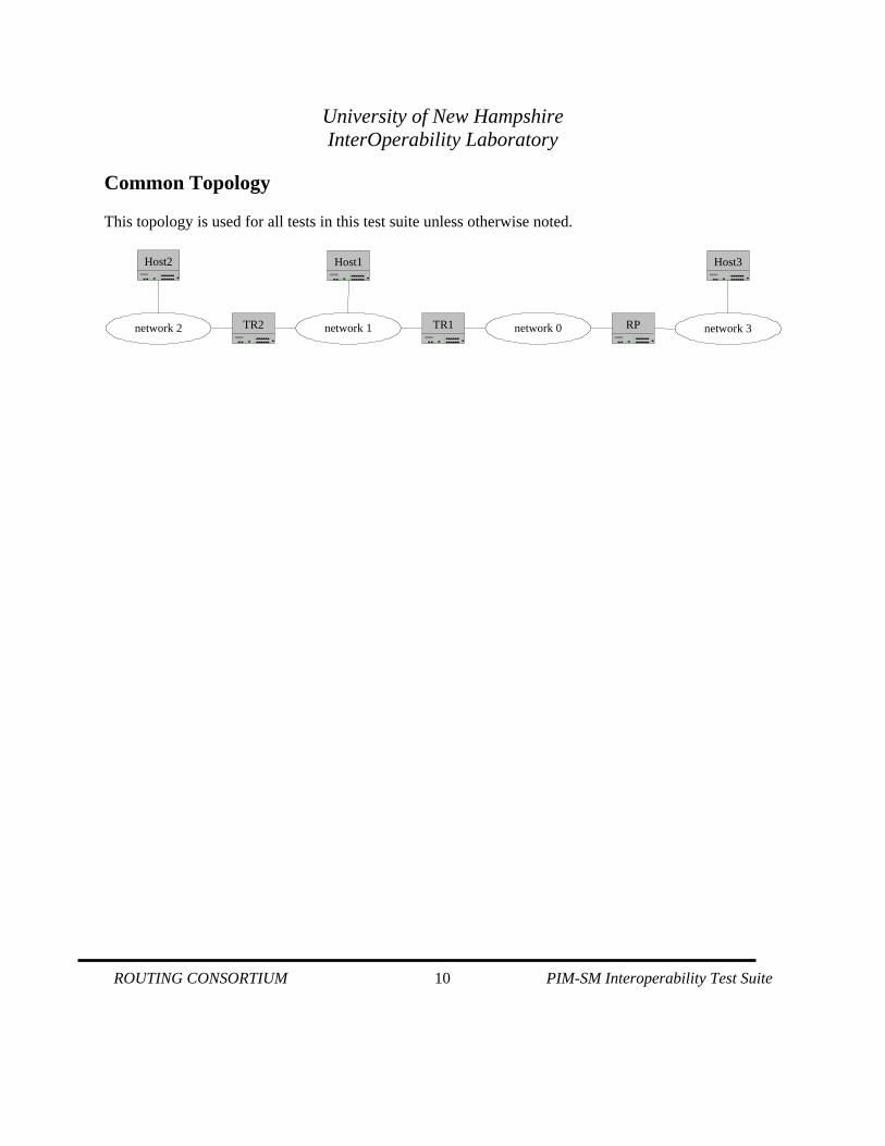
Common Topology This topology is used for all tests in this test suite unless otherwise noted.
TR2 TR1 RP
Host2 Host1 Host3
network 2 network 1 network 0 network 3
University of New Hampshire InterOperability Laboratory
ROUTING CONSORTIUM 11 PIM-SM Interoperability Test Suite
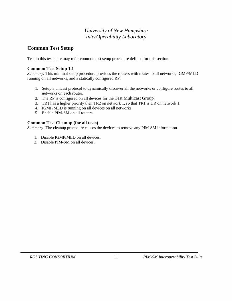
Common Test Setup Test in this test suite may refer common test setup procedure defined for this section. Common Test Setup 1.1 Summary: This minimal setup procedure provides the routers with routes to all networks, IGMP/MLD running on all networks, and a statically configured RP.
1. Setup a unicast protocol to dynamically discover all the networks or configure routes to all networks on each router.
2. The RP is configured on all devices for the Test Multicast Group. 3. TR1 has a higher priority then TR2 on network 1, so that TR1 is DR on network 1. 4. IGMP/MLD is running on all devices on all networks. 5. Enable PIM-SM on all routers.
Common Test Cleanup (for all tests) Summary: The cleanup procedure causes the devices to remove any PIM-SM information.
1. Disable IGMP/MLD on all devices. 2. Disable PIM-SM on all devices.
University of New Hampshire InterOperability Laboratory
ROUTING CONSORTIUM 12 PIM-SM Interoperability Test Suite
Section 1: Hello Messages and Designated Router Election Scope: The following tests are designed to verify interoperability with Hello messaging and DR Election for PIM-SM. Overview: PIM Routers transmit Hello Messages to notify other PIM-SM routers of their presence on a network. Designated Router Election is performed in order to elect a router to forward multicast data on a given subnet. Hello messages are also the way that option negotiation takes place in PIM, so that additional functionality can be enabled, or parameters tuned.
University of New Hampshire InterOperability Laboratory
ROUTING CONSORTIUM 13 PIM-SM Interoperability Test Suite
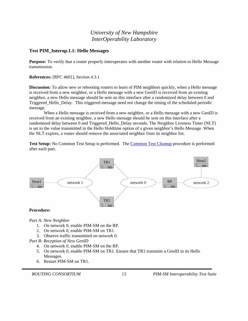
Test PIM_Interop.1.1: Hello Messages Purpose: To verify that a router properly interoperates with another router with relation to Hello Message transmission. References: [RFC 4601], Section 4.3.1 Discussion: To allow new or rebooting routers to learn of PIM neighbors quickly, when a Hello message is received from a new neighbor, or a Hello message with a new GenID is received from an existing neighbor, a new Hello message should be sent on this interface after a randomized delay between 0 and Triggered_Hello_Delay. This triggered message need not change the timing of the scheduled periodic message.
When a Hello message is received from a new neighbor, or a Hello message with a new GenID is received from an existing neighbor, a new Hello message should be sent on this interface after a randomized delay between 0 and Triggered_Hello_Delay seconds. The Neighbor Liveness Timer (NLT) is set to the value transmitted in the Hello Holdtime option of a given neighbor’s Hello Message. When the NLT expires, a router should remove the associated neighbor from its neighbor list. Test Setup: No Common Test Setup is performed. The Common Test Cleanup procedure is performed after each part.
TR2
TR1
RPHost1
Host2
network 1 network 0 network 2
Procedure: Part A: New Neighbor
1. On network 0, enable PIM-SM on the RP. 2. On network 0, enable PIM-SM on TR1. 3. Observe traffic transmitted on network 0.
Part B: Reception of New GenID 4. On network 0, enable PIM-SM on the RP. 5. On network 0, enable PIM-SM on TR1. Ensure that TR1 transmits a GenID in its Hello
Messages. 6. Restart PIM-SM on TR1.

University of New Hampshire InterOperability Laboratory
ROUTING CONSORTIUM 14 PIM-SM Interoperability Test Suite
7. Observe traffic transmitted on network 0. 8. Repeat steps 4 through 6, restarting the RP.
Part C: Holdtime in Hello Messages 9. On network 0, enable PIM-SM on the RP. 10. On network 0, enable PIM-SM on TR1. Ensure that TR1 transmits a Holdtime value of
Default_Hello_Holdtime. 11. Disable PIM-SM on TR1. 12. Observe traffic transmitted on network 0. 13. Repeat steps 9 through 12, disabling the RP.
Observable Results:
• Part A Step 3: The RP should transmit a Hello Message after a randomized delay between 0 and Triggered_Hello_Delay seconds. The RP and TR1 should set its NLT to the value transmitted in the Hello Holdtime Option of the RP.
• Part B Step 7: The RP should transmit a Hello Message after a randomized delay between 0 and Triggered_Hello_Delay seconds upon reception of a Hello Message with a new GenID from TR1. Step 8: TR1 should transmit a Hello Message after a randomized delay between 0 and Triggered_Hello_Delay seconds upon reception of a Hello Message with a new GenID from the RP.
• Part C Step 12: The RP should wait Default_Hello_Holdtime seconds before removing TR1 from its neighbor list. Step 13: TR1 should wait Default_Hello_Holdtime seconds before removing the RP from its neighbor list.
Possible Problems:
• A device may not transmit a GenID in Hello Messages.
University of New Hampshire InterOperability Laboratory
ROUTING CONSORTIUM 15 PIM-SM Interoperability Test Suite
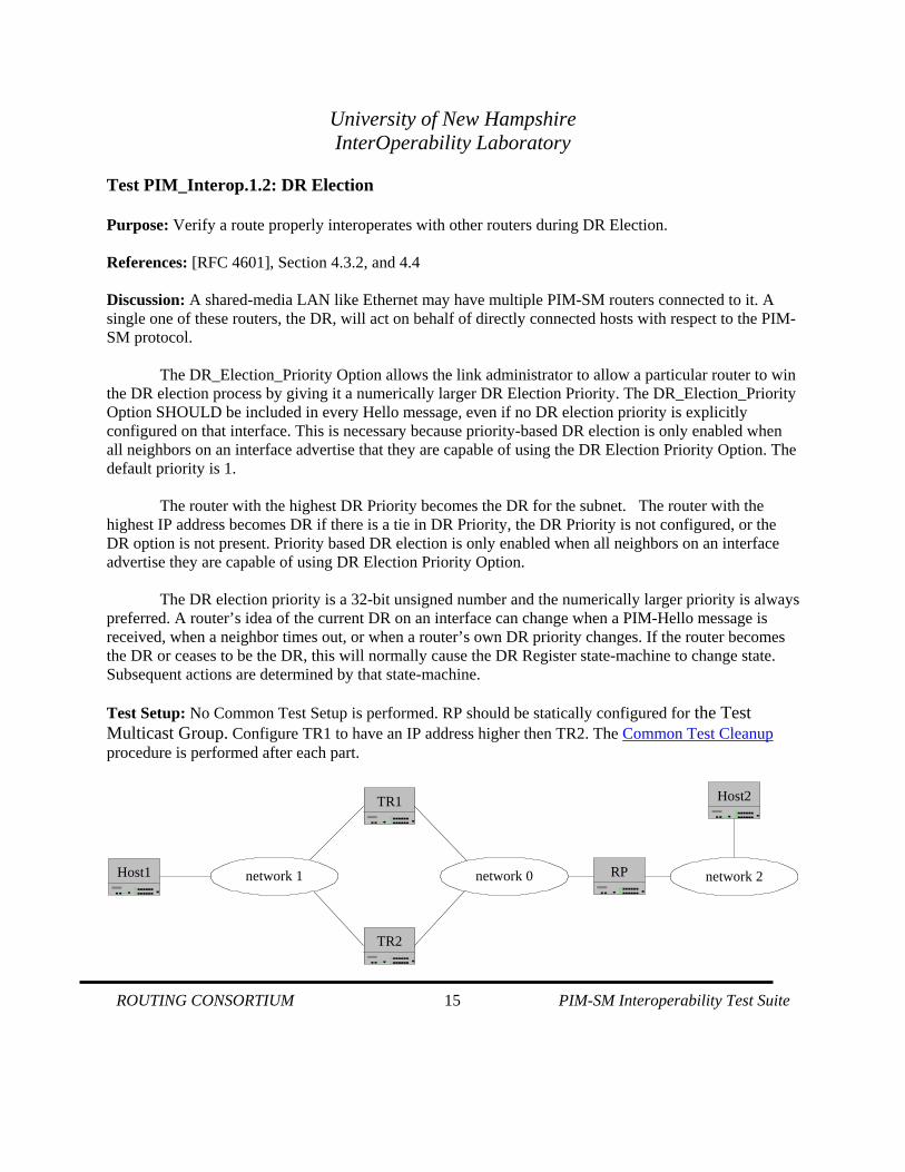
Test PIM_Interop.1.2: DR Election Purpose: Verify a route properly interoperates with other routers during DR Election. References: [RFC 4601], Section 4.3.2, and 4.4 Discussion: A shared-media LAN like Ethernet may have multiple PIM-SM routers connected to it. A single one of these routers, the DR, will act on behalf of directly connected hosts with respect to the PIM-SM protocol.
The DR_Election_Priority Option allows the link administrator to allow a particular router to win the DR election process by giving it a numerically larger DR Election Priority. The DR_Election_Priority Option SHOULD be included in every Hello message, even if no DR election priority is explicitly configured on that interface. This is necessary because priority-based DR election is only enabled when all neighbors on an interface advertise that they are capable of using the DR Election Priority Option. The default priority is 1.
The router with the highest DR Priority becomes the DR for the subnet. The router with the
highest IP address becomes DR if there is a tie in DR Priority, the DR Priority is not configured, or the DR option is not present. Priority based DR election is only enabled when all neighbors on an interface advertise they are capable of using DR Election Priority Option.
The DR election priority is a 32-bit unsigned number and the numerically larger priority is always
preferred. A router’s idea of the current DR on an interface can change when a PIM-Hello message is received, when a neighbor times out, or when a router’s own DR priority changes. If the router becomes the DR or ceases to be the DR, this will normally cause the DR Register state-machine to change state. Subsequent actions are determined by that state-machine. Test Setup: No Common Test Setup is performed. RP should be statically configured for the Test Multicast Group. Configure TR1 to have an IP address higher then TR2. The Common Test Cleanup procedure is performed after each part.
TR2
TR1
RPHost1
Host2
network 1 network 0 network 2
University of New Hampshire InterOperability Laboratory
ROUTING CONSORTIUM 16 PIM-SM Interoperability Test Suite
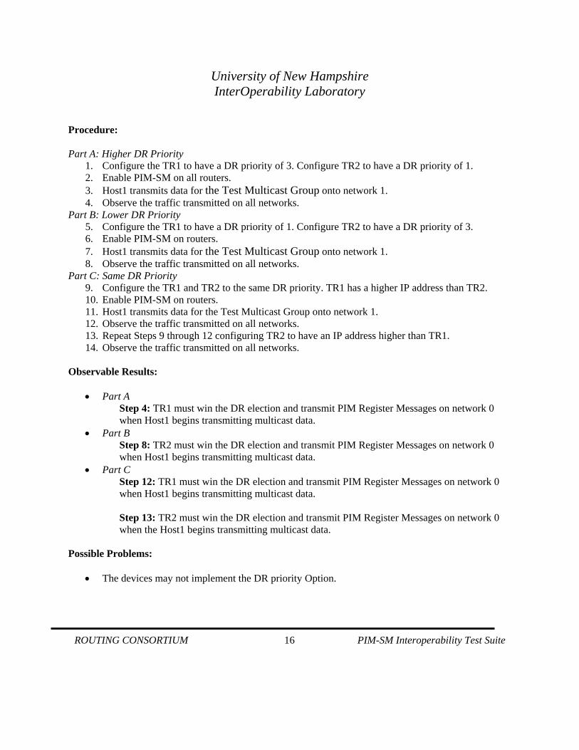
Procedure: Part A: Higher DR Priority
1. Configure the TR1 to have a DR priority of 3. Configure TR2 to have a DR priority of 1. 2. Enable PIM-SM on all routers. 3. Host1 transmits data for the Test Multicast Group onto network 1. 4. Observe the traffic transmitted on all networks.
Part B: Lower DR Priority 5. Configure the TR1 to have a DR priority of 1. Configure TR2 to have a DR priority of 3. 6. Enable PIM-SM on routers. 7. Host1 transmits data for the Test Multicast Group onto network 1. 8. Observe the traffic transmitted on all networks.
Part C: Same DR Priority 9. Configure the TR1 and TR2 to the same DR priority. TR1 has a higher IP address than TR2. 10. Enable PIM-SM on routers. 11. Host1 transmits data for the Test Multicast Group onto network 1. 12. Observe the traffic transmitted on all networks. 13. Repeat Steps 9 through 12 configuring TR2 to have an IP address higher than TR1. 14. Observe the traffic transmitted on all networks.
Observable Results:
• Part A Step 4: TR1 must win the DR election and transmit PIM Register Messages on network 0 when Host1 begins transmitting multicast data.
• Part B Step 8: TR2 must win the DR election and transmit PIM Register Messages on network 0 when Host1 begins transmitting multicast data.
• Part C Step 12: TR1 must win the DR election and transmit PIM Register Messages on network 0 when Host1 begins transmitting multicast data. Step 13: TR2 must win the DR election and transmit PIM Register Messages on network 0 when the Host1 begins transmitting multicast data.
Possible Problems:
• The devices may not implement the DR priority Option.
University of New Hampshire InterOperability Laboratory
ROUTING CONSORTIUM 17 PIM-SM Interoperability Test Suite
Section 2: Join/Prune Messages Scope: The following tests are designed to verify interoperability with Join and Prune messaging in PIM-SM. Overview: Join and Prune messages are dependent upon a per-interface state machine kept by a router. A state machine is kept for (*, *, RP), (*, G), (S, G), and (S, G, rpt) states on each interface.
University of New Hampshire InterOperability Laboratory
ROUTING CONSORTIUM 18 PIM-SM Interoperability Test Suite
Test PIM_Interop.2.1: (*, G) Join Messages Purpose: To verify that routers properly handle (*, G) Join messages. References: [RFC 4601], Section 4.5 Discussion: A PIM Join/Prune message consists of a list of groups and a list of Joined and Pruned sources for each group. When processing a received Join/Prune message, each Joined or Pruned source for a Group is effectively considered individually, and applies to one or more of the following state machines. When considering a Join/Prune message whose Upstream Neighbor Address field addresses this router, (*, G) Joins and Prunes can affect both the (*, G) and (S, G, rpt) downstream state machines, while (*, *, RP), (S, G) and (S, G, rpt) Joins and Prunes can only affect their respective downstream state machines. When considering a Join/Prune message whose Upstream Neighbor Address field addresses another router, most Join or Prune messages could affect each upstream state machine. Test Setup: The Common Test Setup 1.1 is performed before each part. The Common Test Cleanup procedure is performed after each part. Procedure: Part A: Propagate a (*, G) Join message
1. On network 2, Host2 transmits an IGMP/MLD Join message for the Test Multicast Group. 2. Observe traffic transmitted on all networks. 3. Host3 transmits data for the Test Multicast Group onto network 3. 4. Observe traffic transmitted on all networks.
Part B: Generate a (*, G) Join message 5. On network 1, Host1 transmits an IGMP/MLD Join message for the Test Multicast Group. 6. Observe traffic transmitted on all networks. 7. Host3 transmits data for the Test Multicast Group onto network 3. 8. Observe traffic transmitted on all networks.
Part C: Expire Timer 9. On network 1, Host1 transmits an IGMP/MLD Join message for the Test Multicast Group. 10. Observe traffic transmitted on all networks. 11. Host3 transmits data for the Test Multicast Group onto network 3. 12. Observe traffic transmitted on all networks. 13. On network 1, Host1 transmits an IGMP/MLD Join message for the Test Multicast Group. 14. Observe traffic transmitted on all networks.
Observable Results:
• Part A
University of New Hampshire InterOperability Laboratory
ROUTING CONSORTIUM 19 PIM-SM Interoperability Test Suite
Step 2: TR2 must generate a (*, G) Join for the Test Multicast Group. TR1 must forward the (*, G) Join message to the RP on network 0. Step 4: The RP must forward the multicast data from network 3 onto network 0.
• Part B Step 6: TR1 must generate a (*, G) Join message for the Test Multicast Group with the RP as the upstream neighbor on network 0. Step 8: The RP must forward the multicast data from network 3 onto network 0.
• Part C Step 10: TR1 must generate a (*, G) Join message for the Test Multicast Group with the RP as the upstream neighbor on network 0. Step 12: The RP must forward the multicast data from network 3 onto network 0. Step 14: After the Expiry Timer expires TR1 must transmit a (*, G) Join message for the Test Multicast Group with the RP as the upstream neighbor.
Possible Problems:
• None.
University of New Hampshire InterOperability Laboratory
ROUTING CONSORTIUM 20 PIM-SM Interoperability Test Suite
Test PIM_Interop.2.2: (*, G) Prune Messages Purpose: To verify that routers properly handle (*, G) Prune messages. References: [RFC 4601], Section 4.5 Discussion: A PIM Join/Prune message consists of a list of groups and a list of Joined and Pruned sources for each group. When processing a received Join/Prune message, each Joined or Pruned source for a Group is effectively considered individually, and applies to one or more of the following state machines. When considering a Join/Prune message whose Upstream Neighbor Address field addresses this router, (*, G) Joins and Prunes can affect both the (*, G) and (S, G, rpt) downstream state machines, while (*, *, RP), (S, G) and (S, G, rpt) Joins and Prunes can only affect their respective downstream state machines. When considering a Join/Prune message whose Upstream Neighbor Address field addresses another router, most Join or Prune messages could affect each upstream state machine. Test Setup: The Common Test Setup 1.1 is performed before each part. The Common Test Cleanup procedure is performed after each part. Procedure: Part A: Propagate a (*, G) Prune message
1. On network 2, Host2 transmits an IGMP/MLD Join message for the Test Multicast Group. 2. Observe traffic transmitted on all networks. 3. Host3 transmits data for the Test Multicast Group onto network 3. 4. Observe traffic transmitted on all networks. 5. On network 2, Host2 transmits an IGMP/MLD Leave message for the Test Multicast Group. 6. Observe traffic transmitted on all networks. 7. Host3 transmits data for the Test Multicast Group onto network 3. 8. Observe traffic transmitted on all networks.
Part B: Generate a (*, G) Prune message 9. On network 1, Host1 transmits an IGMP/MLD Join message for the Test Multicast Group. 10. Observe traffic transmitted on all networks. 11. Host3 transmits data for the Test Multicast Group onto network 3. 12. Observe traffic transmitted on all networks. 13. On network 1, Host1 transmits an IGMP/MLD Leave message for the Test Multicast Group. 14. Observe traffic transmitted on all networks. 15. Host3 transmits data for the Test Multicast Group onto network 3. 16. Observe traffic transmitted on all networks.
Observable Results:
• Part A
University of New Hampshire InterOperability Laboratory
ROUTING CONSORTIUM 21 PIM-SM Interoperability Test Suite
Step 2: TR2 must generate a (*, G) Join for the Test Multicast Group. TR1 must forward the (*, G) Join Message to the RP on network 0. Step 4: The RP must forward the multicast data from network 3 onto network 0. Step 6: TR2 must generate a (*, G) Prune message for the Test Multicast Group. TR1 must forward the (*, G) Prune message with the RP as the upstream neighbor. Upon receiving the Prune message the RP must stop forwarding multicast data onto network 0. Step 8: The RP must not forward multicast data from network 3 onto network 0.
• Part B Step 10: TR1 must generate a (*, G) Join message for the Test Multicast Group with an upstream neighbor of the RP. Step 12: The RP must forward the multicast data from network 3 onto network 0. Step 14: TR1 must generate a (*, G) Prune message for the Test Multicast Group with the RP as the upstream neighbor. Upon receiving the Prune message the RP must stop forwarding multicast data onto network 0. Step 16: The RP must not forward multicast data from network 3 onto network 0.
Possible Problems:
• TR2 may be disabled in the event of DR conflict
University of New Hampshire InterOperability Laboratory
ROUTING CONSORTIUM 22 PIM-SM Interoperability Test Suite
Test PIM_Interop.2.3: (S, G) Join messages Purpose: To verify that a router properly handles (S, G) Join messages. References: [RFC 4601], Section 4.5 Discussion: A PIM Join/Prune message consists of a list of groups and a list of Joined and Pruned sources for each group. When processing a received Join/Prune message, each Joined or Pruned source for a Group is effectively considered individually, and applies to one or more of the following state machines. When considering a Join/Prune message whose Upstream Neighbor Address field addresses this router, (*, G) Joins and Prunes can affect both the (*, G) and (S, G, rpt) downstream state machines, while (*, *, RP), (S, G) and (S, G, rpt) Joins and Prunes can only affect their respective downstream state machines. When considering a Join/Prune message whose Upstream Neighbor Address field addresses another router, most Join or Prune messages could affect each upstream state machine. Test Setup: The Common Test Setup 1.1 is performed before each part. The Common Test Cleanup procedure is performed after each part. Procedure: Part A: RP Generates (S, G) Join message
1. Host2 continuously transmits data for the Test Multicast Group onto network 2. 2. TR2 transmits Register Messages to the RP on network 1. 3. Observe traffic transmitted on all networks.
Part B: TR1 Generates (S, G) Join message 4. Host3 continuously transmits data for the Test Multicast Group onto network 3. 5. On network 1, Host1 transmits an IGMP/MLD Join message for the Test Multicast Group. 6. Observe traffic transmitted on all networks.
Part C: Expiry Timer for (S, G) 7. Host3 continuously transmits data for the Test Multicast Group onto network 3. 8. On network 1, Host1 transmits an IGMP/MLD Join message for the Test Multicast Group. 9. Observe traffic transmitted on all networks. 10. On network 1, Host1 transmits an IGMP/MLD Join message for the Test Multicast Group. 11. Observe traffic transmitted on all networks.
Observable Results:
• Part A Step 3: The RP generates a (S, G) Join message with a source of Host2 and the Test Multicast Group on network 0. TR1 must forward the (S, G) Join message onto network 1.
• Part B
University of New Hampshire InterOperability Laboratory
ROUTING CONSORTIUM 23 PIM-SM Interoperability Test Suite
Step 6: TR1 should generate a (S, G) Join message with a source of Host3 and the Test Multicast Group. Multicast data for the Test Multicast Group must be forwarded by TR1 onto network 0.
• Part C Step 9: TR1 should generate a (S, G) Join message with a source of Host3 and the Test Multicast Group. Multicast data for the Test Multicast Group must be forwarded by TR1 onto network 0. Step 11: After the Expiry Timer expires TR1 must transmit a (*, G) Join message for the Test Multicast Group with the RP as the upstream neighbor.
Possible Problems:
• TR1 may not support Shortest-Path Tree.
University of New Hampshire InterOperability Laboratory
ROUTING CONSORTIUM 24 PIM-SM Interoperability Test Suite
Test PIM_Interop.2.4: (S, G) Prune messages Purpose: To verify that a router properly handles (S, G) Prune messages. References: [RFC 4601], Section 4.5 Discussion: A PIM Join/Prune message consists of a list of groups and a list of Joined and Pruned sources for each group. When processing a received Join/Prune message, each Joined or Pruned source for a Group is effectively considered individually, and applies to one or more of the following state machines. When considering a Join/Prune message whose Upstream Neighbor Address field addresses this router, (*, G) Joins and Prunes can affect both the (*, G) and (S, G, rpt) downstream state machines, while (*, *, RP), (S, G) and (S, G, rpt) Joins and Prunes can only affect their respective downstream state machines. When considering a Join/Prune message whose Upstream Neighbor Address field addresses another router, most Join or Prune messages could affect each upstream state machine. Test Setup: The Common Test Setup 1.1 is performed before each part. The Common Test Cleanup procedure is performed after each part. Procedure: Part A: (S, G) Prune message
1. Host3 continuously transmits data for the Test Multicast Group onto network 3. 2. On network 1, Host1 transmits an IGMP/MLD Join message for the Test Multicast Group. 3. Observe traffic transmitted on all networks. 4. On network 1, Host1 transmits an IGMP/MLD Leave message for the Test Multicast Group. 5. Observe traffic transmitted on all networks.
Part B: Propagate (S, G) Prune message 6. Host3 continuously transmits data for the Test Multicast Group onto network 3. 7. On network 2, Host2 transmits an IGMP/MLD Join message for the Test Multicast Group. 8. Observe traffic transmitted on all networks. 9. On network 2, Host2 transmits an IGMP/MLD Leave message for the Test Multicast Group. 10. Observe traffic transmitted on all networks.
Part C: Propagate (S, G, rpt) Prune message 11. Host3 transmits data for the Test Multicast Group onto network 3. 12. On network 2, Host2 transmits an IGMP/MLD Join message for the Test Multicast Group. 13. Observe traffic transmitted on all networks. 14. On network 2, Host2 transmits an IGMP/MLD Leave message for the Test Multicast Group. 15. Observe traffic transmitted on all networks.
University of New Hampshire InterOperability Laboratory
ROUTING CONSORTIUM 25 PIM-SM Interoperability Test Suite
Observable Results:
• Part A Step 3: TR1 should generate a (S, G) Join message with a source of Host3 and the Test Multicast Group. Multicast data for the Test Multicast Group must be forwarded by TR1 onto network 0. Step 5: TR1 should generate a (S, G) Prune message with a source of Host3 and the Test Multicast Group. Multicast data for the Test Multicast Group must not be forwarded by TR1 onto network 0.
• Part B Step 8: TR2 should generate a (S, G) Join message with a source of Host3 and the Test Multicast Group. Multicast data for the Test Multicast Group must be forwarded by TR1 onto network 0. Step 10: TR2 should generate a (S, G) Prune message with a source of Host3 and the Test Multicast Group. TR1 must forward the (S, G) message to the RP. Multicast data for the Test Multicast Group must not be forwarded by TR1 onto network 0.
• Part C Step 13: TR2 should generate a (S, G) Join message with a source of Host3 and the Test Multicast Group. TR1 must forward the Prune message to the RP. Step 15: TR2 should generate a (S, G, rpt) Prune message with a source of Host3 and the Test Multicast Group. TR2 must forward the Prune message to the RP.
Possible Problems:
• TR1 may not support Shortest-Path Tree. • TR2 may be disabled in the event of DR conflict
University of New Hampshire InterOperability Laboratory
ROUTING CONSORTIUM 26 PIM-SM Interoperability Test Suite
Section 3: Multicast Forwarding Scope: The following tests are designed to verify multicast forwarding in PIM-SM. Overview: When a router is connected to a multicast network, PIM-SM must make certain decisions to ensure forwarding of data is properly accomplished.
University of New Hampshire InterOperability Laboratory
ROUTING CONSORTIUM 27 PIM-SM Interoperability Test Suite
Test PIM_Interop.3.1: Register Messages Purpose: To verify that a router properly handles Register messages. References: [RFC 4601], Section 4.4 Discussion: The Designated Router (DR) on a LAN or point-to-point link encapsulates multicast packets from local sources to the RP for the relevant group unless it recently received a Register-Stop message for that (S, G) or (*, G) from the RP. When the DR receives a Register-Stop message from the RP, it starts a Register-Stop Timer to maintain this state. Just before the Register-Stop Timer expires, the DR sends a Null-Register Message to the RP to allow the RP to refresh the Register-Stop information at the DR. If the Register-Stop Timer actually expires, the DR will resume encapsulating packets from the source to the RP. Test Setup The Common Test Setup 1.1 is performed before each part. The Common Test Cleanup procedure is performed after each part. Procedure: Part A: Forward Register Message
1. Host2 transmits data for the Test Multicast Group onto network 2. 2. Observe traffic transmitted on all networks. 3. On network 3, Host3 transmits an IGMP/MLD join for the Test Multicast Group. 4. Observe traffic transmitted on all networks.
Part B: Processing Register Messages 5. Host1 transmits data for the Test Multicast Group onto network 1. 6. Observe traffic transmitted on all networks. 7. On network 3, Host3 transmits an IGMP/MLD Join message for the Test Multicast Group. 8. Observe traffic transmitted on all networks.
Observable Results:
• Part A Step 2: TR2 must encapsulate the multicast data on network 2 and send a Register Message to TR1. TR1 must forward the Register Message to the RP on network 0. Step 4: The RP must forward the multicast data from the Register Message received on network 0 onto network 3.
• Part B Step 6: TR1 encapsulates the multicast data on network 1 and sends a Register Message to the RP. Step 8: The RP must forward the multicast data from the Register Messages received on network 0 onto network 3.
University of New Hampshire InterOperability Laboratory
ROUTING CONSORTIUM 28 PIM-SM Interoperability Test Suite
Possible Problems:
• None.
University of New Hampshire InterOperability Laboratory
ROUTING CONSORTIUM 29 PIM-SM Interoperability Test Suite
Test PIM_Interop.3.2: Multicast Data Forwarding Purpose: To verify that a router properly handles forwarding multicast data. References: [RFC 4601], Section 4.4 Discussion: The PIM-SM packet forwarding rules are defined below in pseudo code. iif is the incoming interface of the packet. S is the source address of the packet. G is the destination address of the packet (group address). RP is the address of the Rendezvous Point for this group. RPF_interface (S) is the interface the MRIB indicates would be used to route packets to S. RPF_interface (RP) is the interface the MRIB indicates would be used to route packets to RP, except
at the RP when it is the decapsulation interface (the "virtual" interface on which register packets are received).
First, we restart (or start) the Keepalive Timer if the source is on a directly connected subnet. Second, we check to see if the SPTbit should be set because we've now switched from the RP tree to the SPT. Next we check to see whether the packet should be accepted based on TIB state and the interface that the packet arrived on. If the packet should be forwarded using (S, G) state, we then build an outgoing interface list for the packet. If this list is not empty, then we restart the (S, G) state Keepalive Timer. If the packet should be forwarded using (*, *, RP) or (*, G) state, then we just build an outgoing interface list for the packet. We also check if we should initiate a switch to start receiving this source on a shortest path tree. Finally we remove the incoming interface from the outgoing interface list we've created, and if the resulting outgoing interface list is not empty, we forward the packet out of those interfaces. Test Setup: The Common Test Setup 1.1 is performed before each part. The Common Test Cleanup procedure is performed after each part. Procedure: Part A: Forward multicast data, intermediate router
1. On network 3, Host3 transmits an IGMP/MLD join for the Test Multicast Group.
University of New Hampshire InterOperability Laboratory
ROUTING CONSORTIUM 30 PIM-SM Interoperability Test Suite
2. Host2 transmits data for the Test Multicast Group onto network 2. 3. Observe traffic transmitted on all networks. 4. The RP generates a (S, G) Join message with a source of Host2 and the Test Multicast Group. 5. Observe traffic transmitted on all networks.
Part B: Forward multicast data, end router 6. On network 3, Host3 transmits an IGMP/MLD Join message for the Test Multicast Group. 7. Host1 transmits data for the Test Multicast Group onto network 1. 8. Observe traffic transmitted on all networks. 9. The RP generates a (S, G) Join message with source of Host1 and the Test Multicast Group. 10. Observe traffic transmitted on all networks.
Observable Results:
• Part A Step 3: TR2 must encapsulate the multicast data on network 2 and sends a Register Message to TR1. TR1 must forward the Register Message to the RP on network 0. The RP must forward the multicast data from the Register Message received on network 0 onto network 3. Step 5: TR2 must start to forward multicast data for the Test Multicast Group onto network 1. TR1 must forward the data onto network 0.
• Part B Step 8: TR1 encapsulates the multicast data on network 2 and sends a Register Message to the RP. The RP must forward the multicast data from the Register Messages received on network 0 onto network 3. Step 10: TR1 must start to forward multicast data for the Test Multicast Group onto network 0.
Possible Problems:
• The RP might not support the Shortest Path Tree.
University of New Hampshire InterOperability Laboratory
ROUTING CONSORTIUM 31 PIM-SM Interoperability Test Suite
Test PIM_Interop.3.3: RegisterStop Messages Purpose: To verify that a router properly handles RegisterStop Messages. References: [RFC 4601], Section 4.4 Discussion: The Designated Router (DR) on a LAN or point-to-point link encapsulates multicast packets from local sources to the RP for the relevant group unless it recently received a Register-Stop message for that (S, G) or (*, G) from the RP. When the DR receives a Register-Stop message from the RP, it starts a Register-Stop Timer to maintain this state. Just before the Register-Stop Timer expires, the DR sends a Null-Register Message to the RP to allow the RP to refresh the Register-Stop information at the DR. If the Register-Stop Timer actually expires, the DR will resume encapsulating packets from the source to the RP. Test Setup: The Common Test Setup 1.1 is performed before each part. The Common Test Cleanup procedure is performed after each part. Procedure: Part A: Generate RegisterStop Messages
1. On network 3, Host3 transmits an IGMP/MLD join for the Test Multicast Group. 2. Host2 transmits data for the Test Multicast Group onto network 2. 3. Observe traffic transmitted on all networks. 4. The RP generates a (S, G) Join message with a source of Host2 and the Test Multicast Group. 5. TR2 forwards multicast data for the Test Multicast Group onto network 1. TR1 forwards the data
onto network 0. 6. Observe traffic transmitted on all networks.
Part B: Receive RegisterStop Messages 7. On network 3, Host3 transmits an IGMP/MLD Join message for the Test Multicast Group. 8. Host1 transmits data for the Test Multicast Group onto network 1. 9. Observe traffic transmitted on all networks. 10. The RP generates a (S, G) Join message with source of Host1 and the Test Multicast Group. 11. Observe traffic transmitted on all networks.
Observable Results:
• Part A Step 3: TR2 must encapsulate the multicast data on network 2 and sends a Register Message to TR1. TR1 must forward the Register Message to the RP on network 0.The RP must forward the multicast data from the Register Message received on network 0 onto network 3.
University of New Hampshire InterOperability Laboratory
ROUTING CONSORTIUM 32 PIM-SM Interoperability Test Suite
Step 6: Upon receiving Register messages and multicast data the RP should transmit a RegisterStop message to TR2. TR1 should forward the RegisterStop message from network 0 to network 1.
• Part B Step 9: TR1 encapsulates the multicast data on network 2 and sends a Register Message to the RP. The RP must forward the multicast data from the Register Messages received on network 0 onto network 3. Step 11: TR1 must start to forward multicast data for the Test Multicast Group onto network 0. Upon receiving Register messages and multicast data the RP should transmits a RegisterStop messages to TR1. TR1 should stop transmitted Register messages after receiving the RegisterStop message.
Possible Problems:
• None.