Embed Size (px)
Citation preview

International Journal of Scientific Research and Management Studies (IJSRMS)
ISSN: 23493771 Volume 2 Issue 1, pg: 31-44
http://www.ijsrms.com ©IJSRMS pg. 31
IDENTIFYING ALTERNATIVES FOR CONVENTIONAL PIPES
USING CAE TECHNIQUES FOR PLASTIC COMPOSITES
1Manju Nirale, 2S. G. Dambhare, 3Swapnil S. Kulkarni 12nd Yr M.E. Mechanical. Engineering (Design), P.V.P.I.T, Bavdhan, Pune.
2Prof., Padmabhooshan Vasantdada Patil Institute of Technology Pune, India. 3Director-Able Technologies India Pvt. Ltd., Pune, India
ABSTRACT
The conventional material used for a general purpose pipe carrying fluid has the limitations while being
attempted for use under high stress environmental conditions. The current application which calls for
underground use of the pipe carrying fluids (Including water or gases) is being designed to withstand harsh
conditions of crushing pressure (and/or corrosive environment). Use of general purpose steel or any such
material may not warrant its usability under these trying conditions. The proposed work would attempt to find
an optimal solution in terms of weight (and/or cost) while complying to the performance standards set in the
industry for such applications. The use of fiber reinforced plastics and/or metal impregnated plastics (metal
pipe with suitable thick plastic coatings) appear to be suitable candidates for this dissertation work. The design
alternatives would be evaluated using FEA software for structural strength experienced under practical working
conditions. The same would be tried and tested through physical experimentation while validating the Design
for this work.
KEYWORDS: Structures Composite Laminated Composite Materials, Stress Analysis.
I. INTRODUCTION
Considerable attentions of many industries have been devoted to increasing the utilization and
integration of laminated anisotropic composite into many structural applications [1]. The development
of sandwich structure have possess several properties that make them attractive such as highly
resistant to many corrosive chemicals and compounds that the steel previously lacked, Composites
also have higher strength and stiffness to weight ratios compared to traditional engineering materials
such as steel and concrete [2]. Their low weight can help reduce installation and repair costs; under
transverse and longitudinal compressive loading condition it has good shock absorption characteristics
[3]. Another important advantage of composites is the designer's ability to tailor the material
properties for a specific application. High metal content provides maximum physical strength and
high resin content provides maximum corrosion resistance. Thus the designer can combine these two
elements to produce a satisfactory design.
Among their applications, the composite structure can be used in offshore, submarines, pressure
vessels and civil engineering structures [2]. Here in this project we are using composite as Composite
pipe made of metal impregnated plastics (metal pipe with suitable thick plastic coatings) have many
potential advantages over pipes made from conventional materials. The Trans Canadian pipeline have
wrapped steel pipe with composites to improve the structural properties, while at the same time
adding external corrosion resistance. Composites are significantly lighter than steel. In fact, when
strength-to-weight ratios are examined, composites can be much stronger than steel.
In the present report, we have studied different type of composite materials and observed that many
theoretical and experimental researches are carried out on the failure fibre reinforced composite pipe
with different winding angles[3],so that we have selected laminated structural composite as material
for composite pipe.
International Journal of Scientific Research and Management Studies (IJSRMS)
ISSN: 23493771 Volume 2 Issue 1, pg: 31-44
http://www.ijsrms.com ©IJSRMS pg. 32
In manufacturing process, composite pipe made up of five layers inside and outside layer are made of
plastic tightly bonded with melt adhesive to the mid-layer of aluminium core which is longitudinally
welded and subjected to transverse and longitudinal compressive loading condition . All layers are
extruded by one step.
Fig.1: Composite Pipe
Analytical models of different variants of structural laminated composite pipes such as High-Density
polyethylene (HDPE)-AL-HDPE. PVC-AL- PVC, HDPE-Fibre Tap (FT) – HDPE and PVC-FT-PVC
have been developed. Stress distribution and deflection within the pipe are studied. Simple analytical
method can be used to evaluate the stresses and deflection of multilayer cylindrical structures under
transverse loading conditions .The result of Experimental investigation of composite pipe are
compared to the result of analytical method and theoretical calculations. The value obtained from
experimental results is approximately same with the values obtained from analytical method when
each theory is applied separately.
II. DESIGN MODIFICATION
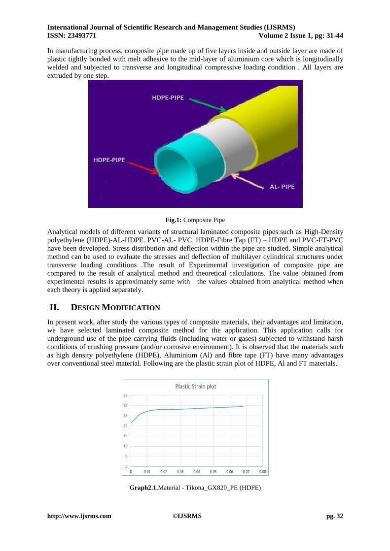
In present work, after study the various types of composite materials, their advantages and limitation,
we have selected laminated composite method for the application. This application calls for
underground use of the pipe carrying fluids (including water or gases) subjected to withstand harsh
conditions of crushing pressure (and/or corrosive environment). It is observed that the materials such
as high density polyethylene (HDPE), Aluminium (Al) and fibre tape (FT) have many advantages
over conventional steel material. Following are the plastic strain plot of HDPE, Al and FT materials.
Graph2.1.Material - Tikona_GX820_PE (HDPE)
International Journal of Scientific Research and Management Studies (IJSRMS)
ISSN: 23493771 Volume 2 Issue 1, pg: 31-44
http://www.ijsrms.com ©IJSRMS pg. 33
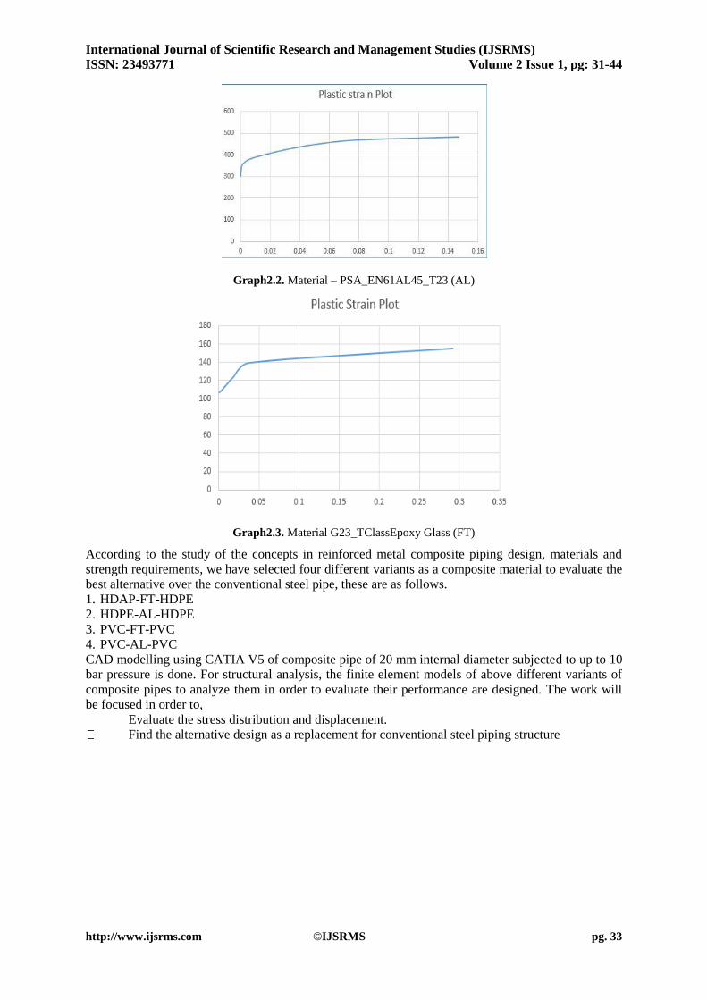
Graph2.2. Material – PSA_EN61AL45_T23 (AL)
Graph2.3. Material G23_TClassEpoxy Glass (FT)
According to the study of the concepts in reinforced metal composite piping design, materials and
strength requirements, we have selected four different variants as a composite material to evaluate the
best alternative over the conventional steel pipe, these are as follows.
1. HDAP-FT-HDPE
2. HDPE-AL-HDPE
3. PVC-FT-PVC
4. PVC-AL-PVC
CAD modelling using CATIA V5 of composite pipe of 20 mm internal diameter subjected to up to 10
bar pressure is done. For structural analysis, the finite element models of above different variants of
composite pipes to analyze them in order to evaluate their performance are designed. The work will
be focused in order to,
Evaluate the stress distribution and displacement.
Find the alternative design as a replacement for conventional steel piping structure

International Journal of Scientific Research and Management Studies (IJSRMS)
ISSN: 23493771 Volume 2 Issue 1, pg: 31-44
http://www.ijsrms.com ©IJSRMS pg. 34
Fig 2.1 . CAD Model of Composite pipe using CATIA V5
The results of CAE analysis for composite pipe having 20 mm internal diameter and 10 bar internal
pressure of different variant are as follows.
Table2.1.The material properties of selecting composite materials are as follows
Fig.2.2. Pipe Composite- HDPE-AL-HDPE
Sr. No Materials Modulus of Elasticity Poission‘s Ratio Yield Stress
1 HDPE 1832 MPa μHDPE = 0.35 σyHDPE = 16.94 MPa
2 Aluminium EAl =73800 MPa μAl = 0.33 σyAl = 300 MPa
3 PVC EPVC = 24000 MPa μpvc =0.41 σypvc= 44.8 MPa

International Journal of Scientific Research and Management Studies (IJSRMS)
ISSN: 23493771 Volume 2 Issue 1, pg: 31-44
http://www.ijsrms.com ©IJSRMS pg. 35
Fig.2.3 FEA Result- HDPE-AL-HDPE
Fig.2.4. Pipe Composite- HDPE-FT-HDPE
International Journal of Scientific Research and Management Studies (IJSRMS)
ISSN: 23493771 Volume 2 Issue 1, pg: 31-44
http://www.ijsrms.com ©IJSRMS pg. 36
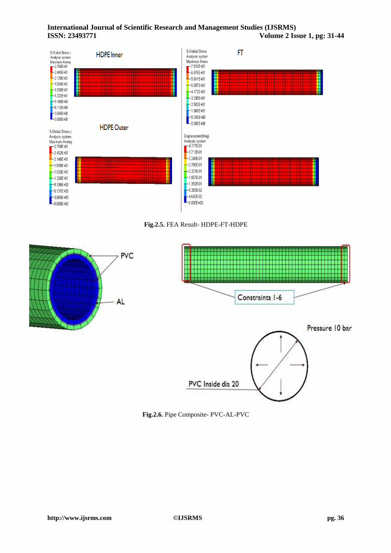
Fig.2.5. FEA Result- HDPE-FT-HDPE
Fig.2.6. Pipe Composite- PVC-AL-PVC
International Journal of Scientific Research and Management Studies (IJSRMS)
ISSN: 23493771 Volume 2 Issue 1, pg: 31-44
http://www.ijsrms.com ©IJSRMS pg. 37
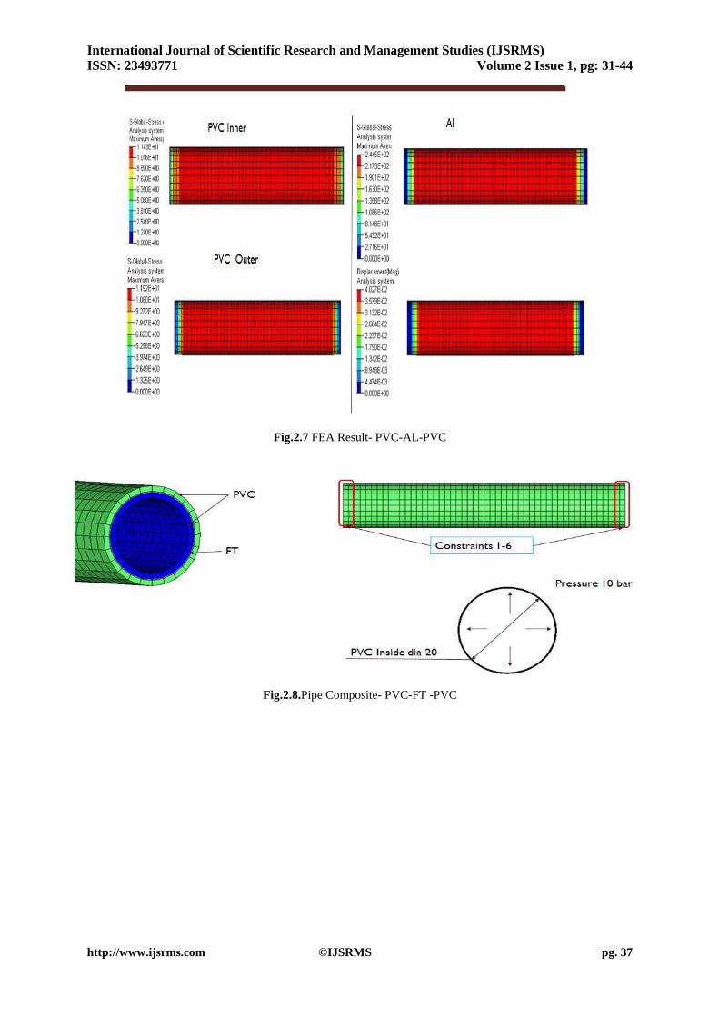
Fig.2.7 FEA Result- PVC-AL-PVC
Fig.2.8.Pipe Composite- PVC-FT -PVC

International Journal of Scientific Research and Management Studies (IJSRMS)
ISSN: 23493771 Volume 2 Issue 1, pg: 31-44
http://www.ijsrms.com ©IJSRMS pg. 38
Fig.2.9. FEA Result- PVC-FT –PVC.
Table2.2 .Comparison Results for internal pressure of composite materials over conventional Steel material.
Stress (Mpa) Strain % Dips (mm) Ply thickness
Zone01 Zone2 Zone03 Zone01 Zone2 Zone03
HDPE-FT-HDPE 27.5 75.01 27.6 1.15 2.2 1.19 0.4 1.2,0.3,1.2
HDPE-AL-HDPE 7.6 302.1 8.1 0 0 0 0.05 1.2,0.3,1.2
PVC-AL- PVC 11.43 244.5 11.92 0 0 0 0.04 1.2,0.3,1.2
PVC-FT-PVC 37.9 55.26 38.86 0 0 0 0.1 1.2,0.3,1.2
Steel 44.24 0 0.002 2.5
After comparing the FEA result of all variants with base pipe, it is observed that the variant HDPE-
AL –HDPE is the best variant for composite pipe subjected to internal pressure up to 10 bars.
III. DESIGN CALCULATION
The functional design of a HDPE-AL-HDPE composite pipe is based on the working fluid,
temperature, and internal pressure. The design factors, which those conditions influence, are the resin
(matrix), reinforcing material (fibre), and wall thickness of the pipe. The functional design of a
composite pipe is well established for a pipe having a circular or conventional cross-sectional profile.
The stress–strain distribution is easily derived from the simple geometry and applicable material
properties; optimization is possible from this information.
On comparing all variant with base pipe in the report HDPE Al HDPE configuration satisfies criteria.
The stresses in a thin-walled HDPE Al HDPE composite pipe which are subjected to External
pressure can be derived
MULTILAYER PIPE CALCULATIONS Pipe with layers of HDPE-AL-HDPE having thickness 1.2-0.3-1.2 mm Applied Force, F = 800
Kg = 8000 N
Outside Diameter of Pipe, D = 25.4 mm Inside Diameter
of Pipe, d = 20 mm Total Thickness of Pipe, t = 5.4 mm
Length of Pipe, L = 150 mm
Equivalent Modulus of Elasticity for Composite, Eeq = 8.5 MPa
Equivalent Poisson‘s Ratio for Composite, μeq = 0.33
External Pressure Acting on Cylinder, po = F/ (2*π*t*L) (1)
= 8000/ (2*π*5.4*150)
International Journal of Scientific Research and Management Studies (IJSRMS)
ISSN: 23493771 Volume 2 Issue 1, pg: 31-44
http://www.ijsrms.com ©IJSRMS pg. 39
Po = 1.572 MPa
Circumferential Stress, σc= po*D/2*t (2)
= 1.572*25.4/2*5.4
σc = 3.7 MPa
Axial Stress, σL = po*D/4*t (3)
= 1.572*25.4/4*5.4
σL = 1.85 MPa
Circumferential Strain, εc = (1/E)*( σc - μeq* σL) (4)
= (1/8.5)*(3.7 – 0.33*1.85)
εc = 0.363
Axial Strain, εc = (1/E)*( σL - μeq* σc) (5)
= (1/8.5)*(1.85 – 0.33*3.7)
εc = 0.074
Displacement, δ = D* εc (6)
= 25.4*0.363
δ =9.22mm
IV. EXPERIMENTATION
Introduction:
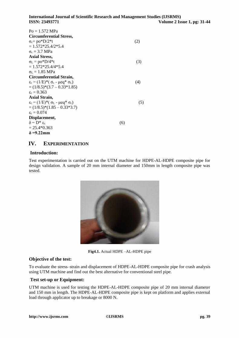
Test experimentation is carried out on the UTM machine for HDPE-AL-HDPE composite pipe for
design validation. A sample of 20 mm internal diameter and 150mm in length composite pipe was
tested.
Fig4.1. Actual HDPE –AL-HDPE pipe
Objective of the test:
To evaluate the stress–strain and displacement of HDPE-AL-HDPE composite pipe for crash analysis
using UTM machine and find out the best alternative for conventional steel pipe.
Test set-up or Equipment:
UTM machine is used for testing the HDPE-AL-HDPE composite pipe of 20 mm internal diameter
and 150 mm in length. The HDPE-AL-HDPE composite pipe is kept on platform and applies external
load through applicator up to breakage or 8000 N.

International Journal of Scientific Research and Management Studies (IJSRMS)
ISSN: 23493771 Volume 2 Issue 1, pg: 31-44
http://www.ijsrms.com ©IJSRMS pg. 40
Fig4.2. Testing on UTM machine
Fig4.3. Actual experimental prototype Fig4.4. Displacement of HDPE-AL-HDPE Composite
pipe after experimentation
CAE analysis of experimental set up
After the experiment test of selected HDPE-AL-HDPE composite materials for external load is
carried out on UTM, CAE analysis is done by creating the CAD model for same experimental set up.
International Journal of Scientific Research and Management Studies (IJSRMS)
ISSN: 23493771 Volume 2 Issue 1, pg: 31-44
http://www.ijsrms.com ©IJSRMS pg. 41
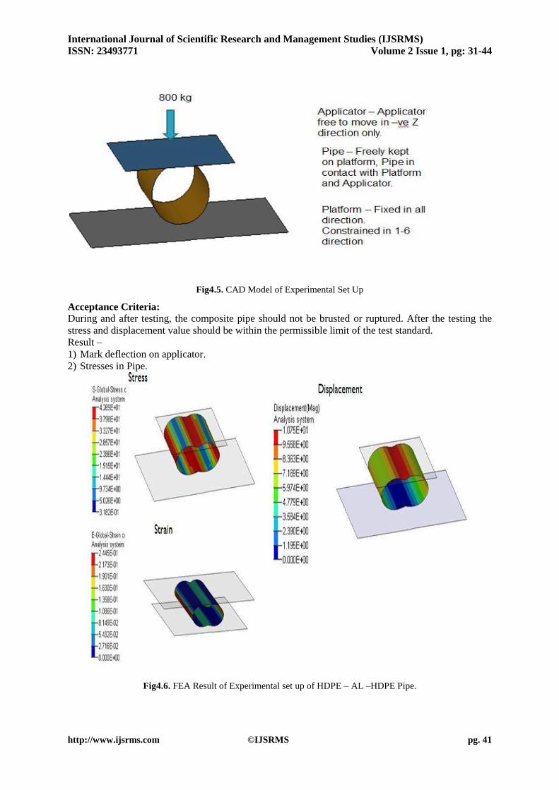
Fig4.5. CAD Model of Experimental Set Up
Acceptance Criteria: During and after testing, the composite pipe should not be brusted or ruptured. After the testing the
stress and displacement value should be within the permissible limit of the test standard.
Result –
1) Mark deflection on applicator.
2) Stresses in Pipe.
Fig4.6. FEA Result of Experimental set up of HDPE – AL –HDPE Pipe.
International Journal of Scientific Research and Management Studies (IJSRMS)
ISSN: 23493771 Volume 2 Issue 1, pg: 31-44
http://www.ijsrms.com ©IJSRMS pg. 42
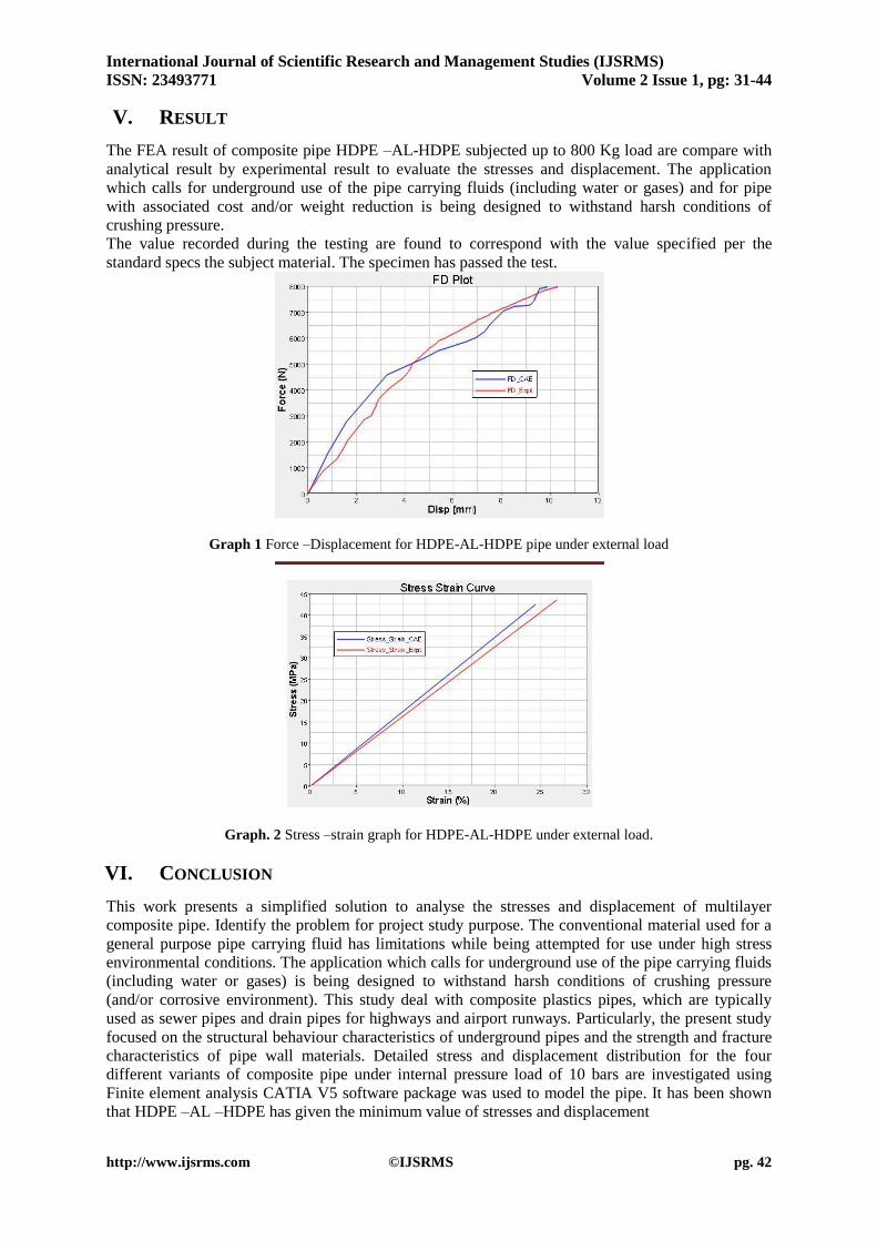
V. RESULT
The FEA result of composite pipe HDPE –AL-HDPE subjected up to 800 Kg load are compare with
analytical result by experimental result to evaluate the stresses and displacement. The application
which calls for underground use of the pipe carrying fluids (including water or gases) and for pipe
with associated cost and/or weight reduction is being designed to withstand harsh conditions of
crushing pressure.
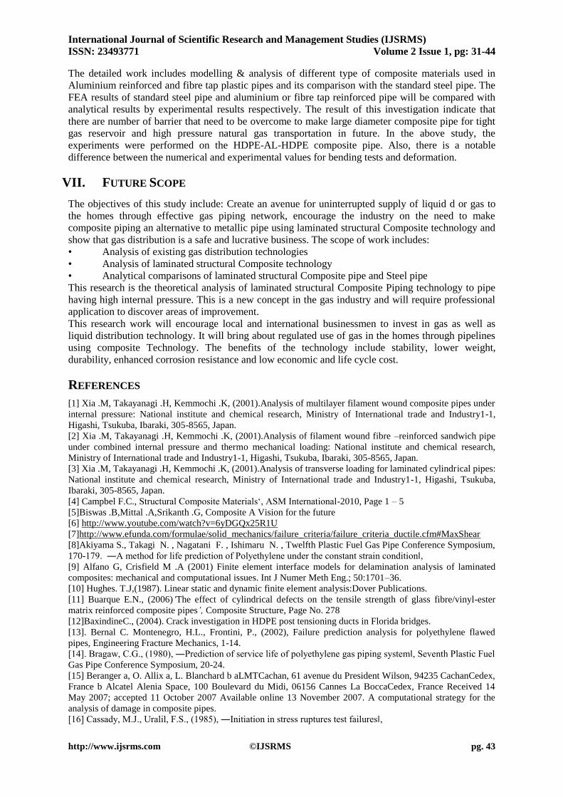
The value recorded during the testing are found to correspond with the value specified per the
standard specs the subject material. The specimen has passed the test.
Graph 1 Force –Displacement for HDPE-AL-HDPE pipe under external load
Graph. 2 Stress –strain graph for HDPE-AL-HDPE under external load.
VI. CONCLUSION
This work presents a simplified solution to analyse the stresses and displacement of multilayer
composite pipe. Identify the problem for project study purpose. The conventional material used for a
general purpose pipe carrying fluid has limitations while being attempted for use under high stress
environmental conditions. The application which calls for underground use of the pipe carrying fluids
(including water or gases) is being designed to withstand harsh conditions of crushing pressure
(and/or corrosive environment). This study deal with composite plastics pipes, which are typically
used as sewer pipes and drain pipes for highways and airport runways. Particularly, the present study
focused on the structural behaviour characteristics of underground pipes and the strength and fracture
characteristics of pipe wall materials. Detailed stress and displacement distribution for the four
different variants of composite pipe under internal pressure load of 10 bars are investigated using
Finite element analysis CATIA V5 software package was used to model the pipe. It has been shown
that HDPE –AL –HDPE has given the minimum value of stresses and displacement
International Journal of Scientific Research and Management Studies (IJSRMS)
ISSN: 23493771 Volume 2 Issue 1, pg: 31-44
http://www.ijsrms.com ©IJSRMS pg. 43
The detailed work includes modelling & analysis of different type of composite materials used in
Aluminium reinforced and fibre tap plastic pipes and its comparison with the standard steel pipe. The
FEA results of standard steel pipe and aluminium or fibre tap reinforced pipe will be compared with
analytical results by experimental results respectively. The result of this investigation indicate that
there are number of barrier that need to be overcome to make large diameter composite pipe for tight
gas reservoir and high pressure natural gas transportation in future. In the above study, the
experiments were performed on the HDPE-AL-HDPE composite pipe. Also, there is a notable
difference between the numerical and experimental values for bending tests and deformation.
VII. FUTURE SCOPE
The objectives of this study include: Create an avenue for uninterrupted supply of liquid d or gas to
the homes through effective gas piping network, encourage the industry on the need to make
composite piping an alternative to metallic pipe using laminated structural Composite technology and
show that gas distribution is a safe and lucrative business. The scope of work includes:
• Analysis of existing gas distribution technologies
• Analysis of laminated structural Composite technology
• Analytical comparisons of laminated structural Composite pipe and Steel pipe
This research is the theoretical analysis of laminated structural Composite Piping technology to pipe
having high internal pressure. This is a new concept in the gas industry and will require professional
application to discover areas of improvement.
This research work will encourage local and international businessmen to invest in gas as well as
liquid distribution technology. It will bring about regulated use of gas in the homes through pipelines
using composite Technology. The benefits of the technology include stability, lower weight,
durability, enhanced corrosion resistance and low economic and life cycle cost.
REFERENCES
[1] Xia .M, Takayanagi .H, Kemmochi .K, (2001).Analysis of multilayer filament wound composite pipes under
internal pressure: National institute and chemical research, Ministry of International trade and Industry1-1,
Higashi, Tsukuba, Ibaraki, 305-8565, Japan.
[2] Xia .M, Takayanagi .H, Kemmochi .K, (2001).Analysis of filament wound fibre –reinforced sandwich pipe
under combined internal pressure and thermo mechanical loading: National institute and chemical research,
Ministry of International trade and Industry1-1, Higashi, Tsukuba, Ibaraki, 305-8565, Japan.
[3] Xia .M, Takayanagi .H, Kemmochi .K, (2001).Analysis of transverse loading for laminated cylindrical pipes:
National institute and chemical research, Ministry of International trade and Industry1-1, Higashi, Tsukuba,
Ibaraki, 305-8565, Japan.
[4] Campbel F.C., Structural Composite Materials‘, ASM International-2010, Page 1 – 5
[5]Biswas .B,Mittal .A,Srikanth .G, Composite A Vision for the future
[6] http://www.youtube.com/watch?v=6yDGQx25R1U
[7]http://www.efunda.com/formulae/solid_mechanics/failure_criteria/failure_criteria_ductile.cfm#MaxShear
[8]Akiyama S., Takagi N. , Nagatani F. , Ishimaru N. , Twelfth Plastic Fuel Gas Pipe Conference Symposium,
170-179. ―A method for life prediction of Polyethylene under the constant strain condition‖,
[9] Alfano G, Crisfield M .A (2001) Finite element interface models for delamination analysis of laminated
composites: mechanical and computational issues. Int J Numer Meth Eng.; 50:1701–36.
[10] Hughes. T.J,(1987). Linear static and dynamic finite element analysis:Dover Publications.
[11] Buarque E.N., (2006)‘The effect of cylindrical defects on the tensile strength of glass fibre/vinyl-ester
matrix reinforced composite pipes’, Composite Structure, Page No. 278
[12]BaxindineC., (2004). Crack investigation in HDPE post tensioning ducts in Florida bridges.
[13]. Bernal C. Montenegro, H.L., Frontini, P., (2002), Failure prediction analysis for polyethylene flawed
pipes, Engineering Fracture Mechanics, 1-14.
[14]. Bragaw, C.G., (1980), ―Prediction of service life of polyethylene gas piping system‖, Seventh Plastic Fuel
Gas Pipe Conference Symposium, 20-24.
[15] Beranger a, O. Allix a, L. Blanchard b aLMTCachan, 61 avenue du President Wilson, 94235 CachanCedex,
France b Alcatel Alenia Space, 100 Boulevard du Midi, 06156 Cannes La BoccaCedex, France Received 14
May 2007; accepted 11 October 2007 Available online 13 November 2007. A computational strategy for the
analysis of damage in composite pipes.
[16] Cassady, M.J., Uralil, F.S., (1985), ―Initiation in stress ruptures test failures‖,

International Journal of Scientific Research and Management Studies (IJSRMS)
ISSN: 23493771 Volume 2 Issue 1, pg: 31-44
http://www.ijsrms.com ©IJSRMS pg. 44
Nineth Plastic Fuel Gas Pipe Conference Symposium, 281-28
[17] Choi, S., Broutman, L.J, (1983), ―Residual stresses in polyethylene pipe, AnnualTechnical Conference-
Society of Plastics Engineers, 378-379
[18] Kaveh .A,Taheri.F,Bending capacity of sandwich pipes; Department of Civil and Resource Engineering,
Dalhousie University, 1360 Barrington Street, Halifax, Nova Scotia, Canada B3J 1Z1,
[19]Huseyin .A,Failure analysis of filament wound composite pipes with an inclined surface crack under static
internal pressure;Selcuk University, Seydisehir Technical College Seydisehir, Konya, Turkey.
[20] Hutar P. a, L. Nahlik a, L. Knesl a, E. Nezbedova b. Article history: Available online 9 October 2009. A
fracture mechanics assessment of surface cracks existing in protective layers of multi-layer composite pipes
[21] Hopkins, I.L., Baker, W.D., Howard, J.B., (1950), ―Complex stressing of polyethylene‖, Journal of
applied physics, v2, n3, 206-213
[22] Hutar P.A, Nahlik A ,ŠestakovaL, ŠevcikM,Knesl Z, NezbedovaE,(2010).Composite Structures 92 1120–
1125.
[23]Soden P .D, Kitching R, T. PC Composites 1989. Experimental failure stresses for 55° filament wound glass
fibre reinforced plastic tubes under biaxial loads.
[24] Zou G, TaheriF(2006)Stress analysis of adhesively bonded sandwich pipeJoints subjected to torsional
loading‘, Journal of Solids and Structure.
[25] Zhong .Y. Analysis of Coated-after Super heater Pipe Bursting Accident in Utility Boiler. A School of
Safety and Environmental Engineering, Capital University of Economics and Business, Beijing 100070, China.
AUTHORS’ BIOGRAPHY
M.S.Nirale is currently working as H.O.D in J.S.P.M’S Bhivrabai Sawant Polytechnic,
Wagholi , Pune, India. I have done B.E from Ram Meghe College of Engineering, Badnera,
Amravati, India. in 2003 and currently doing M.E in Design from Padmabhooshan
Vasantdada Patil Institute of Technology Pune, India. I have published 1 paper in All India
seminar on “CHALLENGES IN ENVIRONMENTAL PROTECTION AND POSSIBLE
SOLUTION” organized by The Institution of Engineers (India) Amravati Local Centre,
Amravati in 2003. My topic of interest is composite and composite materials.
S.G.Dambhare is currently working in Padmabhooshan Vasantdada Patil Institute of
Technology Pune, India. He has done B.E in 1996 and M.E in 2005 and registered for Ph.D.
He has published 8 Papers in International Journals and presented more than 10 papers in
national and international Conferences. He is members of SAE and ISTE. His topic of
interest is sustainable manufacturing, Production Management and Process Modelling.
S.S.Kulkarni Director, Able Technologies India Pvt. Ltd., Pune. The Company offers
Engineering Services and Manufacturing Solutions to Automotive OEM’s and Tier I and
Tier II Companies. He is a Graduate in Industrial Engineering with PG in Operations
Management. With around 20 years of working experience in the domain of R&D, Product
Design and Tool Engineering, he has executed projects in the Automotive, Medical and
Lighting Industry. His area of interest is Research and Development in the Engineering
Industry as well as the emerging sector of Renewable Energy.