Embed Size (px)
Citation preview

installation and servicing
ideal esprit
Your Ideal installation and servicing guide
For details of document amendments, refer to page 3
When replacing any part on this appliance, use only spare parts that you can be assured conform to the safety and performance specification that we require. Do not use reconditioned or copy parts that have not been clearly authorised by Ideal Boilers.
HE24, HE30, HE35For users guide see reverse of book
For the very latest copy of literature for specification purposes please visit our websitewww.idealboilers.com where you will be able to download the relevant information in pdf format.
October 2007 UIN 203642 A02
203642-2.pmd 05/10/2007, 11:541

2 Esprit - Installation and Servicing
203642-2.pmd 05/10/2007, 11:542

3Esprit - Installation and Servicing
DOCUMENT AMENDMENTS
Relevant Installation changes implemented in this book from Mod Level ............... A01 (Sep 07) A02 (Oct 07)
Ideal Stelrad Group reserve the right to vary specification without notice
Page 72• New Techncial Helpline Telephone Number
203642-2.pmd 05/10/2007, 11:543

4 Esprit - Installation and Servicing
GENERAL
Esprit HE24 HE30 HE35Gas supply 2H - G20 - 20mbarGas Supply Connection Rc 1/2 (1/2” BSP female)Injector Size Stereomatic 5.6mm dia. 5.7mm diaInlet Connection Domestic Hot Water 15mm copper compressionOutlet Connection Domestic Hot Water 15mm copper compressionFlow Connection Central Heating 22mm copper compressionReturn Connection Central Heating 22mm copper compressionFlue Terminal Diameter mm (in) 100 (4)Average Flue Temp-Mass Flow Rate (DHW) 66oC-10g/s 74oC - 12 g/s 82oC-14g/sMaximum Working Pressure (Sealed Systems) bar (lb/in2) 2.5 (36.3)Maximum Domestic Hot Water Inlet Pressure* bar (lb/in2) 10.0 (145)Minimum Domestic Hot Water Inlet Pressure bar (lb/in2) 1.0 1.3 1.7**Electrical Supply 230 V ~ 50 Hz.Power Consumption 140 W 175 W 177 WFuse Rating External : 3A Internal : T3.15A L250 VWater content Central Heating litre (gal) 2.0 (0.44)
Domestic Hot Water 0.5 (0.11)Packaged Weight kg (lb) 54.5 (120) 54.8 (121) 55.1 (122)Maximum Installation Weight kg (lb) 46.8 (103) 47.1 (104) 47.4 (105)Boiler Casing Size Height mm (in) 750 (29 1/2)
Width mm (in) 450 (17 3/4)Depth mm (in) 330 (13)
Table 1 - General Data
Note. Gas consumption is calculated using acalorific value of 38.7 MJ/m3 (1038 Btu/ft3) grossor 34.9 MJ/m3 (935 Btu/ft3) nett
To obtain the gas consumption at a differentcalorific value:a. For l/s- divide the gross heat input (kW) by
the gross C.V. of the gas (MJ/m3)b. For ft3/h - divide the gross heat input (Btu/h)
by the gross C.V. of the gas (Btu/ft3)
Key to symbolsGB = United Kingdom IE = Ireland (Countries of destination)
PMS = Maximum operating pressure of water
C13 C33 C53 = A room sealed appliance designed for connection via ducts to ahorizontal or vertical terminal, which admits fresh air to the burnerand discharges the products of combustion to the outside throughorifices which, in this case, are concentric. The fan is up streamof the combustion chamber.
I2H = An appliance designed for use on 2nd Family gas, Group H only.
* The value is used in the UK Government's Standard Assessment Procedure (SAP) for energy rating of dwellings. The test data from which it has been calculated have been certified by a notified body.
CAUTION. To avoid the possibility of injury during the installation, servicing or cleaning ofthis appliance care should be taken when handling edges of sheet steel components
Table 2 - Performance Data - Central Heating
Maximum DHW Input : HE24 HE30 HE35
Nett CV kW 24.3 30.2 36.0
(Btu/h) (82 900) (103 000) (122 800)
Gross CV kW 27.0 33.5 39.9
(Btu/h) (92 100) (114 400) (136 200)
Gas Consumption l/s 0.7 0.87 1.03
(ft3/h) (89.0) (110) (131)
Maximum kW 23.4 29.3 35.2DHW Output (Btu/h) (80 000) (100 000) (120 000)
DHW Flow Rate l/min 9.6 12.0 14.4at 35°C temp. rise. (gpm) (2.1) 2.6 (3.2)
DHW Specific Rate l/min 11.2 14.0 16.8(gpm) (2.5) (3.1) (3.7)
Table 3 - Performance Data - Domestic Hot Water
Boiler Input : Max. Min.
Boiler Input ‘Q’ Nett CV kW 24.4 9.1(Btu/h) (83 300) (31 000)
Gross CV kW 27.1 10.1(Btu/h) (92 500) (34 400)
Gas Consumption l/s 0.70 0.26(ft3/h) (89.0) (33.1)
Boiler Output :Non Condensing kW 23.8 8.870oC Mean Water temp. (Btu/h) (81 200) (30 000)Condensing kW 25.4 9.640oC Mean Water temp. (Btu/h) (86 700) (32 800)
Seasonal efficiency* (SEDBUK) Band A [90.0]%NOx Classification Class 5
*Required for maximum flow rate. Boiler operates down to 0.2 bar.**Note: in areas of low water pressure the DHW restrictor can be removed (Refer to Frame 4).
203642-2.pmd 05/10/2007, 11:544

5Esprit - Installation and Servicing
GENERAL
Boiler size G.C. Appliance No. PI No.(Benchmark No.)
HE24 47 348 46 87 BS 051HE30 47 348 47 87 BS 051HE35 47 348 48 87 BS 051
CONTENTSAir Supply ....................................................................... 8Benchmark Commissioning Checklist ..................... 70Boiler Clearances ....................................................... 10Boiler Exploded Diagram ............................................ 15Condensate Drain .............................................11,22,23Electrical Connections ............................................... 30Extension Ducts - Fitting ............................................. 20Fault Finding ........................................................... 60-64Flow Wiring Diagram .................................................. 33Flue Fitting .................................................................... 18Flue Installation ............................................................. 8Gas Safety Regulations ................................................ 7Gas Supply ..................................................................... 8Installation ............................................................. 13-38Mandatory Requirements ........................................ 7-11Safe Handling ................................................................ 7Servicing ................................................................ 39-58Short List of Parts ....................................................... 65Thermostatic Radiator Valves ................................... 11Water and Systems ........................................... 8,11-13Water Connections ..................................................... 29Water Treatment ......................................................... 13Wiring Diagrams ................................................... 33-34
EspritNatural Gas only
Destination Country: GB, IE
Boiler PageMake and model .......................................................5Appliance serial no. on data badge ...................... 14SEDBUK No. % .........................................................4
ControlsTime and temperature control to heating ............. 31Time and temperature control to hot water .......... 31Heating zone valves ..............................................n/aTRV's ....................................................................... 11Auto bypass ............................................................ 11Boiler interlock ........................................................ 11
For all boilersFlushing to BS.7593 .............................................. 13Inhibitor .................................................................. 13
Central heating modeHeat input ................................................ to be calculated
For assistance see Technical Helpline on the back page
PageBurner operating pressure ....................................n/aCentral heating flow temp. ...... measure and recordCentral heating return temp. ... measure and record
For combination boilers onlyScale reducer .........................................................n/a
Hot water modeHeat input .......................................... to be calculatedMax. operating burner pressure ..............................n/aMax. operating water pressure ........... measure & recordCold water inlet temp ..................... measure & recordHot water outlet temp. .................... measure & recordWater flow rate at max. setting ............ measure & record
For condensing boilers onlyCondensate drain .................................................. 22
For all boilers: complete, sign & hand over to customer
For GB, to comply with Building Regulations Part L1 (Part 6 in Scotland) the boiler should be fitted in accordance with themanufacturer's instructions. Self-certification that the boiler has been installed to comply with Building Regulations can bedemonstrated by completing and signing the Benchmark Commissioning Checklist.
BENCHMARK COMMISSIONING CHECKLIST DETAILS
NOTE TO THE INSTALLER: COMPLETETHE BENCHMARK COMMISSIONING
CHECKLIST AND LEAVE THESEINSTRUCTIONS WITH APPLIANCE
Esp8896(1)
203642-2.pmd 05/10/2007, 11:545

6 Esprit - Installation and Servicing
GENERAL
INTRODUCTIONThe Esprit range of boilers are wall mounted, full sequence,automatic spark ignition, low water content, fanned flue, highefficiency, condensing, combination gas boilers.
Note.Due to the high efficiency of the boiler a plume of watervapour will form at the terminal during operation.
Central heating (CH) output is fully modulating with a range of8.8 to 23.4kW (30,000 to 80,000 Btu/h)
Instantaneous domestic hot water (DHW) output is also fullymodulating with a maximum of :
HE24 23.4kW (80,000 Btu/h)
HE30 29.3kW (100,000 Btu/h)
HE35 35.2kW (120,000 Btu/h)
The boiler is supplied fully assembled with DHW plate heatexchanger, diverter valve, circulating pump, pressure gauge,safety valve and CH expansion vessel.
Variable CH and DHW temperature controls are fitted on theuser control and the boiler features a DHW preheat facility anda preheat ON/OFF switch.
The boiler temperature controls are accessible behind thecasing lower door.
The heat exchanger is of cast aluminium.
The boiler is suitable for connection to fully pumped, sealedwater systems ONLY. Adequate arrangements for completelydraining the system by provision of drain cocks MUST beprovided in the installation pipework.
Pipework from the boiler is routed downwards as standard, butmay be routed upwards behind the boiler using the stand-offframe (supplied in a separate kit).
The boiler includes a filling loop, an automatic by-pass and a75mm condensate trap with integral siphon. Boiler frostprotection is included as standard.
OPERATIONWith no demand for CH, the boiler fires only when DHW isdrawn off, or periodically for a few seconds without any DHWdraw-off, in order to maintain the DHW calorifier in a heatedcondition. (This facility can be turned off if required).
When there is a demand for CH, the heating system issupplied at the selected temperature of between 30 oC and82oC, until DHW is drawn off. The full output from the boiler isthen directed via the diverter valve to the plate heat exchanger tosupply a nominal DHW draw-off of
HE24 9.6 l/min at 35 oC temperature rise.
HE30 12 l/min at 35 oC temperature rise.
HE35 14.4 l/min at 35 oC temperature rise.
The DHW draw off rate specified above is the nominal that theboiler flow regulator will give. Due to system variations andseasonal temperature fluctuations DHW flow rates/temperature rise will vary, requiring adjustment at the draw offtap.
At low DHW draw-off rate the maximum temperature is limitedto 65 oC by the modulating gas control.
Refer also to Frame 1 - 'Boiler Water Circuit Diagrams'
The boiler features a comprehensive diagnostic system whichgives detailed information on the boiler status when operating,and performance of key components to aid commissioning andfault finding.
SAFE HANDLINGThis boiler may require 2 or more operatives to move it to itsinstallation site, remove it from its packaging base and duringmovement into its installation location. Manoeuvring the boilermay include the use of a sack truck and involve lifting, pushingand pulling.
Caution should be exercised during these operations.
Operatives should be knowledgeable in handling techniqueswhen performing these tasks and the following precautionsshould be considered:
• Grip the boiler at the base.
• Be physically capable.
• Use PPE as appropriate, e.g. gloves, safety footwear.
During all manoeuvres and handling actions, every attemptshould be made to ensure the following unless unavoidableand/or the weight is light.
• Keep back straight.
• Avoid twisting at the waist.
• Avoid upper body/top heavy bending.
• Always grip with the palm of the hand.
• Use designated hand holds.
• Keep load as close to the body as possible.
• Always use assistance if required.
OPTIONAL EXTRA KITSFlue Extension Ducts. (1000mm long).HE24-upto 6mHE30-upto 6mHE35-upto 3m
Flue Finishing Kit.90o Elbow Kit (maximum per installation).HE24-upto 4 elbowsHE30-upto 4 elbowsHE35-upto 2 elbows
45o Elbow Kit (maximum per installation).HE24-upto 4 elbowsHE30-upto 4 elbowsHE35-upto 2 elbows
Roof Flue Kit (to a maximum of 7.5m).
Powered Vertical Flue Kit (5m primary and 17m secondary isa typical maximum length. For alternative details refer toPowered Vertical Instructions).
High Level Flue Outlet KitsFlue Deflector KitWeather CollarsTwin Fluing Kits 80mm diameter (up to a maximum of 60mcombined total flue and airducts)Twin Fluing Kits 60mm diameter (up to a maximum of 18mcombined total flue and airducts)Horizontal Flue Terminal 600mm longBoiler Stand-off KitCondensate Pump KitProgrammer Kit - Mechanical 24 hourProgrammer Kit - Electronic 7 dayRF Thermostat/Programmer Kit - Mechanical 24 hourRF Thermostat/Programmer Kit - electronic 7 day
203642-2.pmd 05/10/2007, 11:546
7Esprit - Installation and Servicing
GENERAL
SAFETYCurrent Gas Safety (installation and use) regulations or rulesin force:
The appliance is suitable only for installation in GB and IE andshould be installed in accordance with the rules in force.
In GB, the installation must be carried out by a CORGIRegistered Installer. It must be carried out in accordance withthe relevant requirements of the:
• Gas Safety (Installation and Use) Regulations
• The appropriate Building Regulations either The BuildingRegulations, The Building Regulations (Scotland), BuildingRegulations (northern Ireland).
• The Water Fittings Regulations or Water byelaws inScotland.
• The Current I.E.E. Wiring Regulations.
Where no specific instructions are given, reference should bemade to the relevant British Standard Code of Practice.
In IE, the installation must be carried out by a CompetentPerson and installed in accordance with the current edition ofI.S.813 "Domestic Gas Installations", the current BuildingRegulations and reference should be made to the current ETCIrules for electrical installation.
Detailed recommendations are contained in the following BritishStandard Codes of Practice:
BS. 5440:1 Flues (for gas appliances of rated input notexceeding 70 kW).
BS. 5440:2 Ventilation (for gas appliances of rated input notexceeding 70 kW).
BS. 5449 Forced circulation hot water systems.
BS. 5546 Installation of gas hot water supplies fordomestic purposes (2nd Family Gases)
BS. 6798 Installation of gas fired hot water boilers of ratedinput not exceeding 70 kW.
BS. 6891 Low pressure installation pipes.
Health & Safety Document No. 635.
The Electricity at Work Regulations, 1989.
The manufacturer’s notes must NOT be taken, in any way, asoverriding statutory obligations.
IMPORTANT. These appliances are CE certificated for safetyand performance. It is, therefore, important that no externalcontrol devices, e.g. flue dampers, economisers etc., aredirectly connected to these appliances unless covered by theseInstallation and Servicing Instructions or as otherwiserecommended by Ideal Stelrad Group in writing. If in doubtplease enquire.
Any direct connection of a control device not approved by IdealStelrad Group could invalidate the certification and the normalappliance warranty. It could also infringe the Gas SafetyRegulations and the above regulations.
SAFE HANDLING OF SUBSTANCESCare should be taken when handling the boiler insulationpanels, which can cause irritation to the skin. No asbestos,mercury or CFCs are included in any part of the boiler or itsmanufacture.
LOCATION OF BOILERThe boiler must be installed on a flat and vertical wall, capableof adequately supporting the weight of the boiler and anyancillary equipment.
The boiler may be fitted on a combustible wall and insulationbetween the wall and the boiler is not necessary, unlessrequired by the local authority.
For electrical safety reasons there must be no access availablefrom the back of the boiler.
The boiler must not be fitted outside.
Timber Framed Buildings
If the boiler is to be fitted in a timber framed building it shouldbe fitted in accordance with the Institute of Gas Engineeringdocument IGE/UP/7:1998.
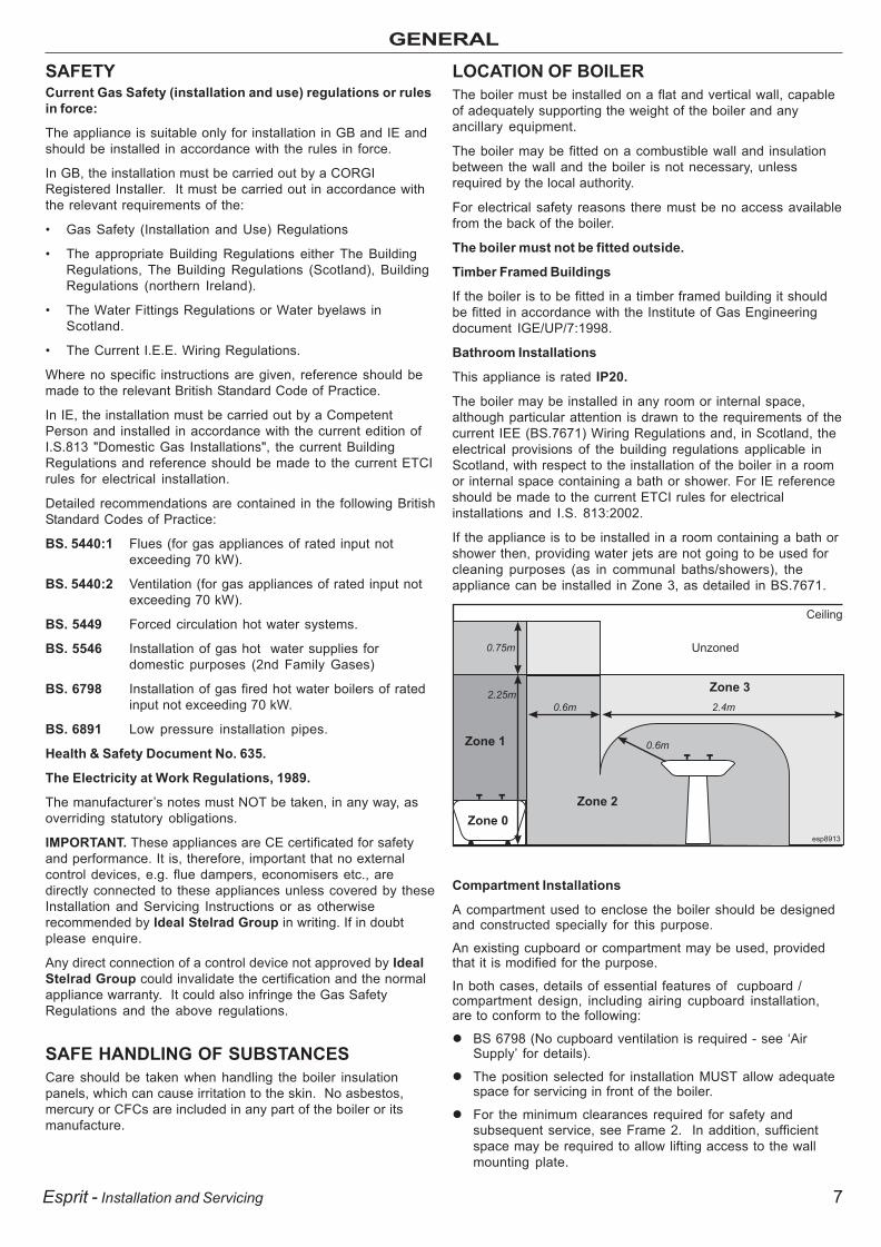
Bathroom Installations
This appliance is rated IP20.
The boiler may be installed in any room or internal space,although particular attention is drawn to the requirements of thecurrent IEE (BS.7671) Wiring Regulations and, in Scotland, theelectrical provisions of the building regulations applicable inScotland, with respect to the installation of the boiler in a roomor internal space containing a bath or shower. For IE referenceshould be made to the current ETCI rules for electricalinstallations and I.S. 813:2002.
If the appliance is to be installed in a room containing a bath orshower then, providing water jets are not going to be used forcleaning purposes (as in communal baths/showers), theappliance can be installed in Zone 3, as detailed in BS.7671.
Compartment Installations
A compartment used to enclose the boiler should be designedand constructed specially for this purpose.
An existing cupboard or compartment may be used, providedthat it is modified for the purpose.
In both cases, details of essential features of cupboard /compartment design, including airing cupboard installation,are to conform to the following:
BS 6798 (No cupboard ventilation is required - see ‘AirSupply’ for details).
The position selected for installation MUST allow adequatespace for servicing in front of the boiler.
For the minimum clearances required for safety andsubsequent service, see Frame 2. In addition, sufficientspace may be required to allow lifting access to the wallmounting plate.
0.75m
2.25m
2.4m
0.6m
0.6m
Zone 1
Zone 0
Zone 2
Unzoned
Ceiling
Zone 3
esp8913
203642-2.pmd 05/10/2007, 11:547

8 Esprit - Installation and Servicing
GENERAL
GAS SUPPLYThe local gas supplier should be consulted, at the installationplanning stage, in order to establish the availability of anadequate supply of gas. An existing service pipe must NOT beused without prior consultation with the local gas supplier.
The boiler MUST be installed on a gas supply with a governedmeter only.
A gas meter can only be connected by the local gas supplier orby a CORGI registered engineer. In IE by a competent person.
An existing meter should be checked, preferably by the gassupplier, to ensure that the meter is adequate to deal with therate of gas supply required.
N.B. The principle of the 1:1 gas valve ensures that the EspritHE range is able to deliver it’s full output at inlet pressuresdown to 14mb. However if dynamic pressures below 20mb areexperienced ensure this is adequate for ALL other gasappliances in the property.
IMPORTANT.Installation pipes must be fitted in accordance with BS.6891. InIE refer to IS.813:2002. Pipework from the meter to the boilerMUST be of an adequate size, i.e. no longer than 20m and notless than 15mm O.D.
The complete installation MUST be tested for gas soundnessand purged as described in the above code.
FLUE INSTALLATIONPluming will occur at the terminal so terminal positions wherethis could cause a nuisance should be avoided.
The flue must be installed in accordance with therecommendations of BS. 5440-1: 2000.In IE refer to I.S. 813:2002.
The following notes are intended for general guidance:
1. The boiler MUST be installed so that the terminal is exposedto external air.
2. It is important that the position of the terminal allows the freepassage of air across it at all times.
3. Minimum acceptable spacing from the terminal toobstructions and ventilation openings are specified inTable 4.
4. Where the lowest part of the terminal is fitted less than 2m(6'6") above a balcony, above ground or above a flat roof towhich people have access then the terminal MUST beprotected by a purpose designed guard.Terminal guards are available from boiler suppliers. (Ask forTFC flue guard model no. K6 - round, plastic coated). In caseof difficulty contact:
Grasslin (UK) Ltd. Tel. + 44 (0) 01732 359 888Tower House, Vale Rise Fax. + 44 (0) 01732 354 445Tonbridge. Kent TN9 1TB www.tfc-group.co.uk
Ensure that the guard is fitted centrally.
5. The flue assembly shall be so placed or shielded as toprevent ignition or damage to any part of any building.
6. The air inlet/products outlet duct and the terminal of theboiler MUST NOT be closer than 25mm (1") to combustiblematerial. Detailed recommendations on the protection ofcombustible material are given in BS. 5440-1:2000.
IMPORTANT. It is absolutely essential to ensure, in practice,that products of combustion discharging from the terminalcannot re-enter the building or any other adjacent buildingthrough ventilators, windows, doors, other sources of naturalair infiltration, or forced ventilation / air conditioning.
If this should occur the appliance MUST be turned OFF,labelled as 'unsafe' until corrective action can be taken.
TERMINALThe terminal assembly can be adapted to accommodatevarious wall thicknesses. Refer to Frame 10 .
AIR SUPPLYIt is NOT necessary to have a purpose-provided air vent in theroom or internal space in which the boiler is installed. Neitheris it necessary to ventilate a cupboard or compartment in whichthe boiler is installed, due to the low surface temperatures ofthe boiler casing during operation; therefore the requirementsof BS 6798, Clause 12, and BS 5440:2 may be disregarded.
WATER CIRCULATION SYSTEMIMPORTANT.A minimum length of 1 metre of copper pipe MUST be fitted toboth flow and return connections from the boiler beforeconnection to any plastic piping.
The central heating system should be in accordance withBS.6798 and, in addition, for smallbore and microboresystems, BS.5449.
WATER TREATMENT - see Frame 6
* Only one reduction down to 25mm is allowable per installation otherwise BS5440-1 2000 dimensions must be followed.
Flue Terminal Positions Min. Spacing*
1. Directly below, above or alongside an openingwindow, air vent or other ventilation opening. 300mm (12")
2. Below guttering, drain pipes or soil pipes. 25mm ( 1")*BS5440-1 2000 75mm (3")
3. Below eaves. 25mm (1")*BS5440-1 2000 200mm (8")
4. Below balconies or a car port roof. 25mm (1")*BS5440-1 2000 200mm (8")
5. From vertical drain pipes or soil pipes. 25mm (1")*BS5440-1 2000 150mm (6")
6. From an internal or external corner or to a 25mm (1")*boundary along side the terminal. BS5440-1 2000 300mm (12")
7. Above adjacent ground, roof or balcony level. 300mm (12")8. From a surface or a boundary facing the terminal. 600mm (24")9. From a terminal facing a terminal. 1,200mm (48")10. From an opening in a car port
(e.g. door or window) into dwelling. 1,200mm (48")11. Vertically from a terminal on the same wall. 1,500mm (60")12. Horizontally from a terminal on the wall. 300mm (12")
Vertical Terminals13. Above the roof pitch with roof slope of all angles. 300mm (12")
Above flat roof. 300mm (12")14. From a single wall face. 300mm (12")
From corner walls. 300mm (12")
Table 4 - Balanced Flue Terminal Position
203642-2.pmd 05/10/2007, 11:548

9Esprit - Installation and Servicing
GENERAL
1 BOILER WATER CIRCUIT DIAGRAMS
CENTRAL HEATING CIRCUIT
DOMESTIC HOT WATER CIRCUIT
ESP8829
Expansion
Vessel
Burner
Automatic
Air Vent
Pressure
Relief Valve
Gas Valve
Pump
Plate Heat
Exchanger
Water Pressure
Gauge
Condensate
Siphon
Divertor
Valve
Sump
Heat
Exchanger
Fan
Expansion
Vessel
Burner
Automatic
Air Vent
Pressure
Relief Valve
Gas Valve
Pump
Plate Heat
Exchanger
Water Pressure
Gauge
Divertor
Valve
Sump
Heat
Exchanger
Fan
Condensate
Dra
in
Condensate
Dra
in
DH
W O
ut
Gas
DH
W In
PR
V
CH
Flo
w
Gas
CH
Retu
rn
PR
V
Condensate
Siphon
203642-2.pmd 05/10/2007, 11:549

10 Esprit - Installation and Servicing
GENERAL
2 BOILER DIMENSIONS, SERVICES & CLEARANCES all dimensions in mm
The boiler connections are made on the boiler. Refer toFrames 30.
The following minimum clearances must be maintained foroperation and servicing.
Additional space will be required for installation, dependingupon site conditions.
Front clearance - The minimum front clearance when built in to a cupboard is 5mm from the cupboard door but 450mmoverall clearance is still required, with the cupboard door open, to allow for servicing.
* Bottom clearance - Bottom clearance after installation can be reduced to 5mm. However, 200mm must be available forservicing.
REAR FLUE ONLYMIN. Top clearance required = 160 mm
SIDE FLUE ONLYHorizontal length of flue Top clearancefrom centre line of boiler required (MIN.)
to outside wall Dim. AHE24 HE30 HE35
0.5 m 0.5 m 0.5 m 160 mm1.0 m 1.0 m 1.0 m 170 mm1.5 m 1.5 m 1.5 m 185 mm2.0 m 2.0 m 2.0 m 200 mm2.5 m 2.5 m 2.5 m 210 mm3.0 m 3.0 m 3.0 m 225 mm3.5 m 3.5 m N/A 250 mm4.0 m 4.0 m N/A 260 mm4.5 m 4.5 m N/A 265 mm5.0 m 5.0 m N/A 275 mm5.5 m 5.5 m N/A 290 mm6.0 m 6.0 m N/A 300 mm
450
460
55
330
750
BOILER DIMENSIONSCLEARANCES
200*
160
Side and Rear FlueProvided that the flue hole is cut accurately, e.g. with a core drill,the flue can be installed from inside the building where wallthicknesses do not exceed 600mm. Where the space into whichthe boiler is going to be installed is less than the length of fluerequired the flue must be fitted from the outside.
esp8820
PR
V
CH
Retu
rn
DH
W I
n
Gas
DH
W O
ut
CH
Flo
w
Condensate
Dra
in
446570466549
53
129 31
WATER AND GAS CONNECTIONS
203642-2.pmd 05/10/2007, 11:5410

11Esprit - Installation and Servicing
GENERAL
General
1. The installation must comply with all relevant national andlocal regulations.
2. The installation should be designed to work with flowtemperatures of up to 82 oC.
3. All components of the system must be suitable for a workingpressure of 3 bar and temperature of 110 oC. Extra care shouldbe taken in making all connections so that the risk of leakageis minimised.
The following components are incorporated within theappliance:
a. Circulating pump.
b. Safety valve, with a non-adjustable preset lift pressure of3 bar.
c. Pressure gauge, covering a range of 0 to 6 bar.
d. An 8-litre expansion vessel, with an initial charge pressureof 1.0 bar.
4. 'Make-up' Water. Provision must be made for replacingwater loss from the system, either :
a. From a manually filled 'make-up' vessel with a readilyvisible water level. The vessel should be mounted atleast 150mm above the highest point of the system andbe connected through a non-return valve to the system,fitted at least 150mm below the 'make-up' vessel on thereturn side of the radiators.
Notes
a. The method of filling, refilling, topping up or flushingsealed primary hot water circuits from the mains via atemporary hose connection is only allowed if acceptableto the local water authority.
b. Antifreeze fluid, corrosion and scale inhibitor fluidssuitable for use with boilers having aluminium heatexchangers may be used in the central heating system.
Advice should be sought from a local water treatmentcompany.
BOILER CONTROL INTERLOCKS
Ideal Stelrad Group recommend that heating systemsutilising full thermostatic radiator valve control of temperaturein individual rooms should also be fitted with a roomthermostat controlling the temperature in a space served byradiators not fitted with such a valve as stated in BS. 5449.
Central heating system controls should be installed toensure the boiler is switched off when there is no demandfor heating or hot water.
When thermostatic radiator valves are used, the spaceheating temperature control over a living / dining area orhallway having a heating requirement of at least 10% of theboiler heat output should be achieved using a roomthermostat, whilst other rooms are individually controlled bythermostatic radiator valves. However, if the system employsthermostatic radiator valves on all radiators, or two portvalves without end switches, then a bypass circuit isincorporated within the boiler to ensure a flow of watershould all valves be in the closed position.
ELECTRICAL SUPPLYWARNING.This appliance must be earthed.Wiring external to the appliance MUST be in accordance withthe current I.E.E. (BS.7671) Wiring Regulations and any localregulations which apply. For IE reference should be made tothe current ETCI rules for electrical installations.The point of connection to the mains should be readilyaccessible and adjacent to the boiler.N.B. THE FAN VOLTAGE IS 325VDC
CONDENSATE DRAIN Refer to Frames 21 & 49.A condensate drain is provided on the boiler. This drain mustbe connected to a drainage point on site. All pipework andfittings in the condensate drainage system MUST be made ofplastic - no other materials may be used.IMPORTANT.Any external runs must be insulated.The drain outlet on the boiler is standard 21.5mm (3/4”)overflow pipe.
3 SYSTEM REQUIREMENTS - Central Heating
or
b. Where access to a 'make-up' vessel would be difficult,by pre-pressurisation of the system.
The maximum cold water capacity of the systemshould not exceed 143 litres, if not pressurized.However, if the system is to be pressurized, theefficiency of the expansion vessel will be reduced anda larger vessel (or smaller system volume) may benecessary. If the capacity of the vessel is notconsidered sufficient for this, or for any other reason,an additional vessel MUST be installed on the returnto the boiler.
Guidance on vessel sizing is given in Frame 3.
Safety valve setting bar 3.0
Vessel charge pressure bar 0.5 to 0.75
System pre-charge pressure bar None 1.0
System volume Expansion vessel(litres) volume (litres)
25 1.6 1.8
50 3.1 3.7
75 4.7 5.5
100 6.3 7.4
125 7.8 9.2
150 9.4 11.0
175 10.9 12.9
190 11.9 14.0
200 12.5 14.7
250 15.6 18.4
300 18.8 22.1
For other system volumesmultiply by the factor across 0.063 0.074
203642-2.pmd 05/10/2007, 11:5411

12 Esprit - Installation and Servicing
GENERAL
4 SYSTEM REQUIREMENTS - CH (continued) and Hot Water
5. Filling
Where the mains pressure is excessive a pressure reducingvalve must be used to facilitate filling.
a. Thoroughly flush out the whole system withcold water.
b. Fill and vent the system until the pressuregauge registers 1.5 bar and examine for leaks.
c. Check the operation of the safety valve byraising the water pressure until the valve lifts.This should occur within 0.3 bar of the preset lift pressure.
d. Release water from the system until theminimum system design pressure is reached;1.0 bar if the system is to be pre-pressurised.
Water Flow Rate and Pressure Loss
Max CH Output kW 23.8
(Btu/h) (81 200)
Water flow rate l/sec 0.38
(gal/min) 4.8
Temperature Differential oC 15
(oF) (27)
Head available for m.w.g. 2.3
system pump. (ft.w.g.) 7.5
DOMESTIC HOT WATER1. The domestic hot water service must be in accordance
with BS 5546 and BS 6700.
2. Refer to Table 1 for minimum and maximum workingpressures.
In areas of low mains water pressures the domestic hotwater restrictor may be removed from the inlet valve. Theboiler will require the flow rate to be set to obtain atemperature rise of 35oC at the tap furthest from the boiler.
3. The boilers are suitable for connection to most types ofwashing machine and dishwasher appliances.
4. When connecting to suitable showers, ensure that:
a. The cold inlet to the boiler is fitted with an approvedanti-vacuum or syphon non-return valve.
b. Hot and cold water supplies to the shower are of equalpressure.
The boiler is fitted with an automatic bypass.
BALANCING1. Set the programmer to ON.
Close the manual or thermostatic valves on all radiators,leaving the twin lockshield valves (on the radiators referredto above) in the OPEN position.
Turn up the room thermostat and adjust these lockshieldvalves to give boiler flow and return temperatures not morethan 20oC apart.
These valves should now be left as set.
5 SYSTEM BALANCING
2. Open all manual or thermostatic radiator valves andadjust the lockshield valves on the remaining radiators,to give around 15 oC temperature drop at each radiator.
3. Adjust the room thermostat and programmer to NORMALsettings.
See note regarding thermostatic radiator valves on page 11.
5. Hard Water AreasWhere the water hardness exceeds 200mg/litre, it isrecommended that a proprietary scale reducing device isfitted into the boiler cold supply within the requirements ofthe local water company.
IMPORTANTProvision MUST be made to accommodate the expansion ofDHW contained within the appliance, if a non-return valve isfitted to the DHW inlet.
203642-2.pmd 05/10/2007, 11:5412

13
INSTALLATION
Esprit - Installation and Servicing
6 WATER TREATMENT
CENTRAL HEATINGThe Esprit range of boilers have an ALUMINIUM alloyheat exchanger.
IMPORTANT.The application of any other treatment to this productmay render the guarantee of Ideal Stelrad Group.
Ideal Stelrad Group recommend Water Treatment inaccordance with the Benchmark Guidance Notes onWater Treatment in Central Heating Systems.
If water treatment is used Ideal Stelrad Group recommendonly the use of FERNOX-COPAL or MB1, GE BETZ SENTINEL X100or Salamander Corrosion Guard inhibitors and associatedwater treatment products, which must be used in accordancewith the manufacturers' instructions.
Notes.
1. It is most important that the correct concentration of thewater treatment products is maintained in accordance withthe manufacturers' instructions.
2. If the boiler is installed in an existing system any unsuitableadditives MUST be removed by thorough cleansing. BS7593:1992 details the steps necessary to clean a domesticheating system.
3. In hard water areas, treatment to prevent lime scale may benecessary - however the use of artificially softened water isNOT permitted.
4. Under no circumstances should the boiler be fired beforethe system has been thoroughly flushed.
DOMESTIC HOT WATER
In hard water areas where main water can exceed 200ppmTotal Hardness (as defined by BS 7593:1993 Table 2) ascale reducing device should be fitted into the boiler coldsupply within the requirements of the local water company.The use of artificially softened water, however, is notpermitted.
Ideal Stelrad Group recommend the use of FernoxQantomat, GE Betz Sentinel Combiguard and CalmagCalPhos I scale reducing devices, which must be used inaccordance with the manufacturers' instructions.
For further information contact:
Fernox Manufacturing Co. LtdCookson ElectronicsForsyth RoadSheerwaterWokingSurrey GU21 5RZ+44 (0) 1799 521133
Sentinel Performance SolutionsThe Heath Business & Technical ParkRuncornCheshire WA7 4QXTel: 0800 389 4670www.sentinel-solutions.net
Salamander Engineering LtdUnit 24 Reddicap Trading EstateSutton ColdfieldWest Midlands B75 7BUTel: +44 (0) 121 3780952
Calmag Ltd.Unit 4-6, Crown WorksBradford RoadSandbeds, KeighleyWest Yorkshire BD20 5LNTel: +44 (0) 1535 210 320
INS
TA
LL
AT
ION
203642-2.pmd 05/10/2007, 11:5413

14
INSTALLATION
Esprit - Installation and Servicing
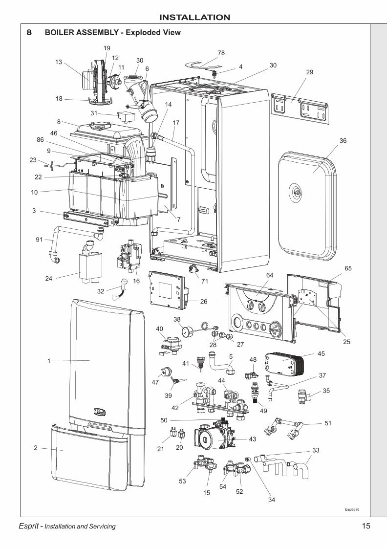
7 BOILER ASSEMBLY - Exploded View Legend1. Front Casing Panel
2. Front Casing Door
3. Sump Cover Plate
4. Flue Sensing Nipple
5. Return Pipe
6. Flue Manifold
7. Interpanel
8. Burner
9. Combustion Chamber Insulation
10. Heat Engine
11. Injector & Housing
12. Venturi
13. Fan
14. Automatic Air Vent (Heat Exchanger)
15. Gas Service Cock
16. Gas Valve
17. Gas Injector Pipe
18. Fan Bracket
19. Orifice Plate
20. Control Thermistor (Flow/Return)
21. Overheat Thermostat
22. Ignition Electrode
23. Flame Sensing Electrode
24. Condensate Trap/Siphon
25. User Control PCB
26. PCB Primary Controls
27. Mains Switch
28. Pre-Heat & Winter/Summer Switch
29. Wall Mounting Bracket
30. Turret Gasket
31. Spark Generator
32. Ignition Lead
33. Connection Pipes
34. Flow Regulator
35. Pressure Relief Valve
36. Expansion Vessel
37. Expansion Vessel Pipe
38. Pressure Gauge
39. DHW Thermistor
40. Diverter Valve Head
41. Diverter Valve Cartridge
42. Flow Group Manifold
43. Pump
44. Return Group Manifold
45. Plate Heat Exchanger
46. Dry Fire Thermistor
47. Water Pressure Switch
48. Reed Switch
49. Reed Switch Cartridge & Filter
50. Air Vent (Pump)
51. Filling Loop
52. Return Valve
53. Flow Valve
54. DHW Valve
64. Control Box Sub Assy
65. Control Box Lid
71. Control Box Hinge
78. Turret Clamp
86. Burner Earth Pin
91. Flow Pipe
INS
TA
LL
AT
ION
203642-2.pmd 05/10/2007, 11:5414
15
INSTALLATION
Esprit - Installation and Servicing
8 BOILER ASSEMBLY - Exploded View
13
1912
1130
6
18
318
8646
923
22
10
3
91
32
21 20
53
1554
52
33
51
35
37
43
42
39
47
415 48
45
49
34
50
44
78
4 3029
36
6465
25
38
26
71
7
17
14
16
1
2
24
28 27
40
Esp8895
203642-2.pmd 05/10/2007, 11:5415

16
INSTALLATION
Esprit - Installation and Servicing
9 UNPACKINGThe boiler is supplied fully assembled in one Pack A, together with a telescopic flueassembly for lengths up to 595mm, rear or side flue outlet, in Pack B.
Unpack and check the contents.
Pack A Contents
A BoilerB Hardware Pack Box
(positioned at bottom of boiler)C Wall Mounting Bracket
(positioned at bottom of boiler)D Installation/Users
InstructionsE Wall Mounting TemplateF 2 Year Guarantee
PACK B CONTENTSA Telescopic flue terminalB Flue turretC ScrewsD Sealing tape
nm8751
AB
C
D
B
CEA
DF
esp8821
Flow Valve Pack Filling Loop PackDHW Pack
Accessory Pack1. Screws x 32. Wall Plugs x33. 1/2" Fibre washer (spare) x 14. 1/2" Gas washer (blue) (spare) x 15. 3/4" Fibre washer (spare) x 1
Gas Pack1. Gas Cock x 12. 1/2" Gas washer (blue) x 13. Gas Inlet Bend 15mm x 1
Return Valve Pack1. Return Valve Assembly2. Outlet bend 22mm3. Fibre Washer
Flow Valve Pack1. Outlet bend 22mm x 12. 22mm CH valve c/w drain, nut & olive x 13. 3/4" Fibre washer x 1
DHW Pack1. Pipe DHW outlet x 12. 15mm valve c/w nut & olive & flow regulator x 13. Inlet bend 15mm x 14. Nut G1/2 x 25. 1/2" Fibre washer x 3
Filling Loop Pack1. Isolating valve c/w double non return valve x 12. Flexible Hose x 1
1
3
2
1
3
1
1
3
2 2
2
4
1
3
2
4
5 1
2
3
5
Gas Pack Return Valve PackAccessory Pack
esp8875
HARDWARE PACK CONTENTS
INS
TA
LL
AT
ION
203642-2.pmd 05/10/2007, 11:5416

17
INSTALLATION
Esprit - Installation and Servicing
Wall thickness X
169 mm
169 + S = 202mm
esp8815
(with optional
stand-off frame)
FLUE KITS
Pack B - supplied as standard
Pack D - optional extension kit for side flue orrear flue outlet.
Finishing Kit - Supplied as an optional extra.
Refer to 'Flue Extension Ducts'
IMPORTANT. The boiler MUST be installed in a vertical position
Dimension X - Wall thickness.
Dimension L - Wall thickness plus boiler spacing.
Dimension S - Optional Stand-off frame depth = 33mm
10 DETERMINING THE FLUE LENGTH AND FLUE PACKS REQUIRED
Notes.1. When extension ‘D’ packs are used the flue duct MUST be inclined
at 1.5 degrees to the horizontal to allow condensate to drain backinto the boiler and out through the condensate drain.
2. If the telescopic ‘B’ pack, or horizontal flue terminal (600 long) onlyare used, they may be mounted horizontally. The 1.5 degrees istaken care of by the inclination of the flue within the air pipe.
3. If the boiler is to be installed with upward piping routed behind theboiler then the optional stand-off kit should be used. Care must betaken when cutting the ducts and marking the wall to suit thiscondition.
Note. MAXIMUM FLUE LENGTHS:HE24 & 30 - 6M (HORIZONTAL FLUE)HE35 - 3M (HORIZONTAL FLUE)HE24, 30 & 35 - 7.5M (ROOF FLUE)HE 24, 30 & 35 - 5M PRIMARY AND 17M SECONDARY IS A
TYPICAL MAX. FLUE LENGTH. (For alternative details refer toPowered Vertical Instructions)
90O ELBOW KIT 60/100 (EQUIVALENT FLUE LENGTH RESISTANCE = 1M)45O ELBOW KIT 60/100 (EQUIVALENT FLUE LENGTH RESISTANCE = 0.6M)HE24, HE30 & HE35 - 18M TOTAL (AIR PLUS FLUE DUCT-60/60 TWIN FLUE KIT)HE24, HE30 & HE35 - 60M TOTAL (AIR PLUS FLUE DUCT - 80/80 TWIN FLUE KIT)NOTE. If the option of a loft terminal grille is used with the 80/80 twin flue, then a minimumof 300mm radial clearance around the grill must be maintained at ALL times.
MINIMUM HORIZONTAL FLUE LENGTHS - TELESCOPIC TERMINAL = 370MM(Centre Line of turret to outside of wall terminal) - ONE PIECE TERMINAL = 285MM
Total Flue length dimension Flue(measuring from CL of turret to outside wall)
Rear flue Side flue Extra packs Boilerdim. X+169 dim. L+225 required Size
Up to 595 mm Up to 595 mm none HE24,30 & 35
Up to 1545 mm Up to 1545 mm Pack D - 1 off HE24,30 & 35
Up to 2495 mm Up to 2495 mm Pack D - 2 off HE24,30 & 35
Up to 3445 mm Up to 3445 mm Pack D - 3 off HE24, 30 & 35*
Up to 4395 mm Up to 4395 mm Pack D - 4 off HE24 & 30
Up to 5345 mm Up to 5345 mm Pack D - 5 off HE24 & 30
Up to 6000 mm Up to 6000 mm Pack D - 6 off HE24 & 30
*Esprit HE35 is capable of 3m flue only
225mm 225mm
Wall thickness X
Side flue length L
SIDE FLUE
REAR FLUE
INS
TA
LL
AT
ION
203642-2.pmd 05/10/2007, 11:5417

18
INSTALLATION
Esprit - Installation and Servicing
2037
07A
01
esp8914
1
2
169mm
Extended
centre
line
12 WALL MOUNTING TEMPLATE
11 FLUE ASSEMBLY - Exploded View
An optional flue duct extension kit is required forwall thicknesses greater than :
Side 365mm (14 3/8")
Rear 426mm (15 3/4").
Rear flue arrangement shown
nm
87
61
LEGEND
1. Duct assembly.
2. Flue turret.
3. Turret gasket.
4. M5 x 10 pozi screw.
5. Turret clamp.
1
esp8822
Note.The template shows the positions of the fixing holes and therear flue outlet hole centre for standard installation. CareMUST be taken to ensure the correct holes are drilled.
1. Tape template into the selected position. Ensuresquareness by hanging a plumbline as shown.
2. If fitting a side flue extend the flue centre line onto the sidewall and measure in 169mm for standard installation.
Note. If using stand-off kit distance increases to 202mm.
3. Mark onto the wall the following:
a The wall mounting plate screwpositions (choose one from eachgroup).
b. The position of the flue duct hole(see diagram).
Note. Mark the centre of the hole as wellas the circumference
4. Remove the template from the wall.
INS
TA
LL
AT
ION
203642-2.pmd 05/10/2007, 11:5418
19
INSTALLATION
Esprit - Installation and Servicing
F
LU
E O
UT
LE
T
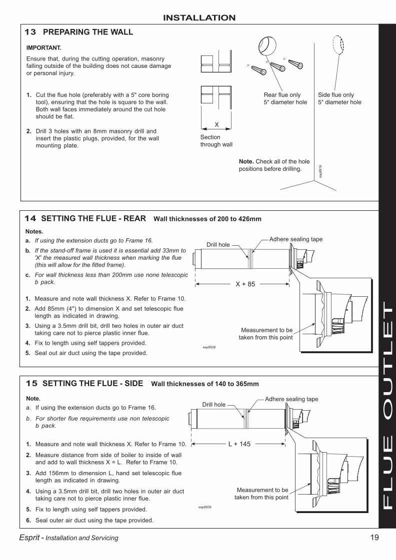
13 PREPARING THE WALL
IMPORTANT.
Ensure that, during the cutting operation, masonryfalling outside of the building does not cause damageor personal injury.
1. Cut the flue hole (preferably with a 5" core boringtool), ensuring that the hole is square to the wall.Both wall faces immediately around the cut holeshould be flat.
2. Drill 3 holes with an 8mm masonry drill andinsert the plastic plugs, provided, for the wallmounting plate.
14 SETTING THE FLUE - REAR Wall thicknesses of 200 to 426mm
Notes.a. If using the extension ducts go to Frame 16.
b. If the stand-off frame is used it is essential add 33mm to'X' the measured wall thickness when marking the flue(this will allow for the fitted frame).
c. For wall thickness less than 200mm use none telescopicb pack.
1. Measure and note wall thickness X. Refer to Frame 10.
2. Add 85mm (4") to dimension X and set telescopic fluelength as indicated in drawing.
3. Using a 3.5mm drill bit, drill two holes in outer air ducttaking care not to pierce plastic inner flue.
4. Fix to length using self tappers provided.
5. Seal out air duct using the tape provided.
15 SETTING THE FLUE - SIDE Wall thicknesses of 140 to 365mm
Note.a. If using the extension ducts go to Frame 16.
b. For shorter flue requirements use non telescopicb pack.
1. Measure and note wall thickness X. Refer to Frame 10.
2. Measure distance from side of boiler to inside of walland add to wall thickness X = L. Refer to Frame 10.
3. Add 156mm to dimension L, hand set telescopic fluelength as indicated in drawing.
4. Using a 3.5mm drill bit, drill two holes in outer air ducttaking care not to pierce plastic inner flue.
5. Fix to length using self tappers provided.
6. Seal outer air duct using the tape provided.
esp8938
X + 85
Drill holeAdhere sealing tape
Measurement to be
taken from this point
esp8939
L + 145
Drill holeAdhere sealing tape
Measurement to be
taken from this point
esp8816
X
Sectionthrough wall
Note. Check all of the holepositions before drilling.
Side flue only5" diameter hole
Rear flue only5" diameter hole
203642-2.pmd 05/10/2007, 11:5419

20
INSTALLATION
Esprit - Installation and Servicing
F
LU
E O
UT
LE
T
1. A maximum of 6 extension ducts for the HE24/HE30 and a maximum of 3 extension ducts forthe HE35 (one suitably cut) plus the standardflue duct may be used together.
2. Flue extensions of greater length than 1m (39")should be supported with the bracket provided,suitably adjusted. Refer to Frames 16 and 24.
17 FLUE EXTENSION DUCTS - continued
18 FITTING THE KIT
16 FLUE EXTENSION DUCTS - For total flue lengths greater than 595mm
Pack D Flue extension duct kit contents
Note. Side flue shown
General arrangement
Flue duct support
Flue support cutting aid (shown folded up)
Wall plugs - 4 off
Extension duct & clamp1.0m (39") long
No. 10 x2" wood screw - 4 offnm8732
nm8762
Boiler
Standard flue
Terminal grille
Flue length
Extension flue
Use a maximum of 6m extended flue ONLY (HE24 & 30)
Use a maximum of 3m extended flue ONLY (HE35)
Because of the flexibility of the telescopic flue terminal it is notalways necessary to cut an extension pack.
1. Measure the total flue length from the centre of the boileroutlet to the outside wall.
2. Subtract 70mm from this dimension.
3. Subtract 950mm for each ‘D’ pack to be used.
4. If the remainder Y is 300mm -525mm this can be taken upby the adjustment in thetelescopic flue.
5. If the remainder Y is 525mm -950mm it will be necessary tocut a ‘D’ pack to 400mm.
6. If the remainder Y is less than 300mm, shorten theprevious ‘D’ pack to 400mm and adjust the telescopicterminal.
7. Measure and mark the length on the flue, to ensure asquare cut mark the flue all the way around and cut tolength.
L
300
525
Y95070
esp8940
203642-2.pmd 05/10/2007, 11:5420

21
INSTALLATION
Esprit - Installation and Servicing
F
LU
E O
UT
LE
T
19 FITTING THE WALL MOUNTING PLATE
Screw the wall mounting plate to thewall using 3 wall plugs (previouslyfitted) with the 3 screws provided.
Choose one of the 3 sets of slots in left,right and centre bank. Ensuring that atleast one of the screws is fitted into atop slot.
esp8817
Example of fixing
20 MOUNTING THE BOILER1. Ensure the plastic plugs are removed
from both the CH and DHW connectionsbefore mounting the boiler.
2. Lift the boiler onto the wall mounting plate(refer to the Introduction section for safehandling advice), locating it over the topangled return.
esp8828
203642-2.pmd 05/10/2007, 11:5421
22
INSTALLATION
Esprit - Installation and Servicing
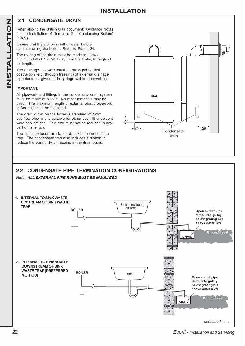
21 CONDENSATE DRAINRefer also to the British Gas document: 'Guidance Notesfor the Installation of Domestic Gas Condensing Boilers'(1989).
Ensure that the siphon is full of water beforecommissioning the boiler . Refer to Frame 24.
The routing of the drain must be made to allow aminimum fall of 1 in 20 away from the boiler, throughoutits length.
The drainage pipework must be arranged so thatobstruction (e.g. through freezing) of external drainagepipe does not give rise to spillage within the dwelling.
IMPORTANT.All pipework and fittings in the condensate drain systemmust be made of plastic. No other materials may beused. The maximum length of external plastic pipeworkis 3m and must be insulated.
The drain outlet on the boiler is standard 21.5mmoverflow pipe and is suitable for either push fit or solventweld applications. This size must not be reduced in anypart of its length.
The boiler includes as standard, a 75mm condensatetrap. The condensate trap also includes a siphon toreduce the possibility of freezing in the drain outlet.
BOILER
esp8880
Sink constitutesair break
DRAIN
Ground Level
Open end of pipe
direct into gulley
below grating but
above water level
BOILER
esp8881
DRAIN
Sink
Ground Level
Open end of pipe
direct into gulley
below grating but
above water level
1. INTERNAL TO SINK WASTEUPSTREAM OF SINK WASTETRAP
2. INTERNAL TO SINK WASTEDOWNSTREAM OF SINKWASTE TRAP (PREFERREDMETHOD)
Note. ALL EXTERNAL PIPE RUNS MUST BE INSULATED
22 CONDENSATE PIPE TERMINATION CONFIGURATIONS
continued . . . .
49
53
129Condensate
Drain
INS
TA
LL
AT
ION
203642-2.pmd 05/10/2007, 11:5422

23
INSTALLATION
Esprit - Installation and Servicing
23 CONDENSATE PIPE TERMINATION CONFIGURATIONS . . . continued
BOILER
esp8882
3. INTERNAL CONNECTION TO SOIL AND VENT STACK* Make connection to SVP using a solvent welded saddle
BOILER
External
wall
Ground Level
Termination
to Soak away
cla7774
minimum
500mm
BOILER
External
wall
Ground Level
Open end of pipe
direct into gulley
below grating but
above water level
DRAIN
cla7775
4. TERMINATION TO SOAK AWAY
5. TERMINATION TO DRAIN / GULLEYIN
ST
AL
LA
TIO
N
203642-2.pmd 05/10/2007, 11:5423

24
INSTALLATION
Esprit - Installation and Servicing
esp8824
2
1
3
24 CONNECTING THE FLUE TO THE BOILER
Note. Before fitting the flue turret fill the condensate trap within theboiler by pouring a cupful of water into the flue outlet A.Take care to ensure that the water is only poured into the flueoutlet, and does not spill into the boiler casing.
1. Locate the flue into the turret.2. Insert the flue assembly through the prepared hole in the
wall. Push through and pull back to seal against outsidewall face.
3. Locate the flue turret on the top of the boiler, ensuring thatthe turret gasket is in place. Also ensure the turret islocated concentric with the flue aperture on the boiler toppanel. Check that the flue seal located in the top of the fluemanifold is secure and giving an effective seal.
4. Secure the flue turret on top of the boiler by inserting theopen ends of the turret clamp under the 2 studs and fixingit in the middle with the single M5 x 10mm pozi-hex screwprovided.
5. Flues over 1 metre long.Fix the flue support bracket to the wall, using the 4 wallplugs and wood screws.NB. The space bracket will utilise one fixing hole onlywhilst used in conjunction with the stand-off option.
INS
TA
LL
AT
ION
203642-2.pmd 05/10/2007, 11:5424

25
INSTALLATION
Esprit - Installation and Servicing
F
LU
E O
UT
LE
T
Note.A flat or pitched roof flashing plate (not supplied) is required beforeproceeding with the installation of this kit.
This kit is suitable for both flat and pitched roof terminations, using aconcentric flue to run vertically from the top of the boiler and terminatingabove roof level.
WEATHER PROOFING
Where the flue passes through the roof line an adequate seal mustbe made. This is achieved by using either:
- Flat roof weather collaror- Universal weather collar.
ACCESSORIES
Flue Duct Extension Kits are available forflue lengths extending beyond 1m. Thesepacks contain 1m extension ducts and maybe cut to the desired length.
If the offset vertical option is used an elbowKit is required. For a full accessories listrefer to page 6, Optional Extras and Frames26 and 28, Flue Arrangement.
Flueduct
support
Vertical connector
UIN 20313590o elbow
UIN 203130
45o elbow
UIN 203131
Roof Flue Extentsion Duct
UIN 203129
nm
87
35
Flue Terminal
UIN 203132
Flue Seal Collar - Flat Roof
UIN 152259
Flue Seal Collar - Tile Roof
UIN 152258
26 ROOF FLUE KIT CONTENTS / OPTIONS
25 FITTING THE OPTIONAL ROOF FLUE KIT (Flat or Pitched)
nm8736
203642-2.pmd 05/10/2007, 11:5425

26
INSTALLATION
Esprit - Installation and Servicing
F
LU
E O
UT
LE
T
rf8394-1
690mmFixed
300mm
min
27 FLUE TERMINAL POSITION
rf8393-1
300mm
min
300mm
min
625mmFixed
Flat roof - with structure
The terminal should be positioned so that products ofcombustion can safely disperse at all times.
Pluming may occur at the termination so, wherepossible, terminal positions where this could causea nuisance should be avoided.
Minimum dimensions are shown below
Terminal Position Minimum DimensionDirectly below an opening,
air brick, windows, etc. 300 mmBelow plastic / painted gutters 300 mm
Painted surface 300 mmBelow eaves or balcony 500 mm
rf8392
203642-2.pmd 05/10/2007, 11:5426

27
INSTALLATION
Esprit - Installation and Servicing
F
LU
E O
UT
LE
T
rf8
73
7
rf8
73
8
28 FLUE ARRANGEMENT
Note.The equivalent flue length resistance of the elbow kits are:90o elbow kit = 1m45o elbow kit = 0.6m
203642-2.pmd 05/10/2007, 11:5427

28
INSTALLATION
Esprit - Installation and Servicing
F
LU
E O
UT
LE
T
29 ASSEMBLING THE ROOF FLUE KITDetermine the correct height that the flue should terminateabove the roof. If after calculating or measuring the overall flueheight from the top of the boiler, it is necessary to cut bothpipes, then ensure they are cut equally leaving the inner fluetube longer than the outer air tube as supplied.
Ensure the cut pipe ends are free from any burrs.
1. Position the roof flashing plate (supplied separately) over thehole cut in the roof and insert flue terminal from the roof end.
esp
88
87
min
16
o
max 4
1o
MAX LENGTH:
7.5m
BOILER
nm8740
Flue Terminal
Pitched roof tile
weather collarFlat roof tile
weather collar
1
esp8850
2
Extension
Duct
Vertical
connector
Turret
clamp
3
nm
8743
'X'4
2. Push fit the vertical connector (supplied separately) into theboiler flue connection and retain with the turret clamp andsecuring screw (supplied with the boiler). ENSURING THEGASKETS IN THE BOILER FLUE OUTLET ARE CORRECTLYFITTED.
3. "Push" fit extension duct (if required (supplied separately)) intovertical connector.
4. If the last extension duct requires cutting, measure ‘X’, the distance(outer ducts), between the duct and the terminal and add 100 mm tothis dimension. This gives the length of the last extension duct.
Note. Check the position of the inner flue duct relative to the outer ducton the assembled extension duct(s) and ensure the terminal flue ductis cut longer than the air duct to ensure engagement in the final flueduct seal.
5. Finally ensure the roof flashing plate is correctly sealed to the roof.
203642-2.pmd 05/10/2007, 11:5428

29
INSTALLATION
Esprit - Installation and Servicing
esp8826
CH Return
Connection
DHW Inlet
Connection
Gas
Connection
DHW Outlet
Connection
CH Flow
Connection
Inlet Pressure
Test Point
Flow
RegulatorFilling Loop Valve
(shown in closed postion)Filling Loop Valve
(shown in closed postion)
CH Filling
Loop
GAS CONNECTIONIMPORTANT. The gas service cock is sealed with a non-metallicblue fibre washer so must not be overheated when making capillaryconnections.
Refer to Frame 2 for details of the position of the gas connection.
N.B. The principle of the 1:1 gas valve ensures that the Esprit HErange is able to deliver it’s full output at inlet pressures down to14mb. However if dynamic pressures below 20mb are experiencedensure this is adequate for ALL other gas appliances in the property.
A boiler gas supply pipe length of 20m and not less than 15mm O.D.can be connected to the boiler via the gas service cock union.
30 WATER AND GAS CONNECTIONS
WATER CONNECTIONS - CHNotes.
1. For heating loads in excess of 60,000 Btu/h use28mm x 22mm connectors to connect the boilerflow and return pipes to 28mm system pipework.
2. Do not subject any of the isolating valves to heat asthe seals may be damaged.
WATER CONNECTIONS - DHWNote. The DHW inlet isolating valve incorporates aflow regulator and a CH filling loop connection.
The safety valve is located at the rear RHS of the boiler service connection area.
The discharge pipe should be positioned so that the discharge of water or steam cannot create a hazard to the occupantsof the premises or damage the electrical components and wiring.
31 SAFETY VALVE DRAIN
INS
TA
LL
AT
ION
32 FILLINGCentral Heating1. Remove the front panel. Refer to Frame 45.2. Ensure that the CH isolating valves are open.3. Fill and vent the system using the filling loop, fitted between the DHW
inlet valve and the CH return valve. Refer to Frame 30 and Frame 4 forsetting pressure.
Check for water soundness.
IMPORTANT - when filling:A. Ensure dust cap on auto air vent is opened up one full turn.B. When filling, there may be a slight water leak from the air vent
therefore electrical connections should be protected.Domestic Hot Water1. Fully open all DHW taps and ensure that water flows freely from them.
2. Close all taps.
Note. The domestic hot water flow rate isautomatically regulated to a maximum:HE24 = 9.6 l/m (2.1 gpm)HE30 = 12.0 l/m (2.6 gpm)HE35 = 14.4 l/m (3.2 gpm)
A
203642-2.pmd 05/10/2007, 11:5429

30
INSTALLATION
Esprit - Installation and Servicing
33 ELECTRICAL CONNECTIONS
Wiring should be 3 core PVC insulated cable, not less than0.75 mm2 (24 x 0.2mm) and no greater than 1.25mm2, andto BS 6500 Table 16.
Connection must be made in a way that allows completeisolation of the electrical supply such as a double poleswitch having a 3mm (1/8") contact separation in bothpoles, or an unswitched plug and socket, serving only theboiler and system controls. The means of isolation must beaccessible to the user after installation.
WARNING. This appliance MUST be earthed.
A mains supply of 230 V ~ 50 Hz is required.
The fuse rating should be 3A. All external controls and wiringmust be suitable for mains voltage.
Wiring external to the boiler MUST be in accordance with thecurrent I.E.E. (BS.7671) Wiring Regulations and any localregulations.
For IE reference should be made to the current ETCI rules forelectrical installations.
34 ELECTRICAL CONNECTIONS - INSTALLER WIRING
L
N
F1
F2
R1
R2
R3
esp
88
25
Pre fitted
mains cable
Pre fitted
link wire
The Esprit boiler comes pre-fitted with 1m of mains cable.This must be connected to a permanent live supply and NOTswitched by thermostats/programmers. For installerswishing to change this cable refer to Frame 35.
The Esprit boiler comes pre-fitted with a link wire between R1and R2 on the terminal strip. This creates a permanent callfor heat and must be removed when adding a roomthermostat/programmer.
To add thermostat/programmer:
1. Isolate the mains supply to the boiler.
2. Remove the front panel. Refer to Frame 45.
3. Swing the control box down into the servicing position.Refer to Frame 46.
4. Remove the terminal block cover to access the terminalsfor electrical connections.
LEGENDL LiveN NeutralF1 Frost Thermostat Switched LiveF2 Frost Thermostat Live FeedR1 Room Thermostat Switched LiveR2 Room Thermostat Live FeedR3 Room Thermostat Switched Live
(When using optional internal programmer kits)
esp8854
4
5. Route incoming cables through cable glands provided, afterremoving air sealing plugs.
6. Connect wires to terminal block, see instructions opposite.
7. Re-fit terminal block cover, nibbling out the plastic as required fromthe cable entry to secure the cables.
8. Tighten cable gland to provide cable anchorage.
9. Swing the control box back up into the operating condition and re-fitthe front panel ensuring a good seal is made.
INS
TA
LL
AT
ION
203642-2.pmd 05/10/2007, 11:5430

31
INSTALLATION
Esprit - Installation and Servicing
34 CONT’D ..........ELECTRICAL CONNECTIONS - INSTALLER WIRING
Ideal Boilers offer 4 kits as follows:(see individual kits for installation instructions)
PROGRAMMER KIT MECHANICAL 24 HOUR- 24 hour mechanical programmer fits into the control box of the boiler. This can befitted in conjunction with a room thermostat.
PROGRAMMER KIT ELECTRONIC 7 DAY - 7 day electronic programmer fits into the control box of the boiler. This can be fitted inconjunction with a room thermostat.
RF THERMOSTAT/PROGRAMMER KIT MECHANICAL 24 HOUR - Combined 24 hour mechanical programmer and roomthermostat with wireless communication to receiver unit which fits into control box of the boiler.
RF THERMOSTAT/PROGRAMMER KIT ELECTRONIC 7 DAY - Combined 7 day programmer and room thermostat with wirelesscommunication to receiver unit which fits into control box of the boiler.
ROOM THERMOSTAT (NO PROGRAMMER)1. Remove link wire between R1 and R2.
2. Connect room thermostat across terminals R1 andR2 as shown in diagram A
3. If room thermostat has a neutral connection,connect this to terminal N.
ROOM THERMOSTAT + PROGRAMMER1. Remove link wire between R1 & R2.
2. Connect room thermostat and programmer inseries as shown in diagram B.
3. If room thermostat has a neutral connection,connect this to terminal N.
FROST THERMOSTATIf parts of the system are vulnerable to freezing or theprogrammer is likely to be left off during cold weather, afrost thermostat should be fitted.
1. Position the frost thermostat in a suitable position,i.e. area vulnerable to freezing.
2. Connect frost thermostat across terminalsF1 and F2 as shown in diagrams A and B.
esp
89
18
OptionalFrost Stat
If required
N
R3 connection is used with integral programmer kit
L
N
F1
F2
R1
R2
R3
RoomStat
esp
89
19
OptionalFrost Stat
ExternalProgrammer
L
N
F1
F2
R1
R2
R3
If required
N
RoomStat
DIAGRAM B - EXTERNAL PROGRAMMER
DIAGRAM A - NO PROGRAMMER
INS
TA
LL
AT
ION
203642-2.pmd 05/10/2007, 11:5431

32
INSTALLATION
Esprit - Installation and Servicing
35 REPLACING PRE-FITTED MAINS CABLE
If it is necessary to use an alternative mains cable to the onepre-fitted then use the following guide.
Replacement wiring should comply with notes in Frame 33.
1. Isolate the mains supply to the boiler.
2. Remove the front panel. Refer to Frame 45.
3. Swing the control box down into the service position.Refer to Frame 46.
4. Remove the terminal block cover to access the terminalsfor electrical connections.
5. Remove the mains cover to access the earth post.
6. Remove the live and neutral wires from the terminal block.
7. Remove the top nut from the earth post and remove theearth connection ring terminal from the post.
8. Slacken the cable gland and withdraw the mains cable.
esp8931
4
5
Earth Post
9. Route replacement cable back through the cable glandand re-tighten to provide cord anchorage.
10. Connect the earth wire to the earth post by trapping thestripped end between the cupped and flat washer. Securewith nut provided.
11. Connect the live and neutral wires to the terminal strip.
When making the mains electrical connections to theboiler it is important that the wires are prepared in such away that the earth conductor is longer than the currentcarrying conductors, such that if the cord anchorageshould slip, the current carrying conductors become tautbefore the earthing conductor.
12. Re-fit the mains and terminal block covers ensuringcables are located in the cable entry position.
13. Swing the control box back up into the operating positionand re-fit the front panel ensuring a good seal is made.
INS
TA
LL
AT
ION
203642-2.pmd 05/10/2007, 11:5432

33
INSTALLATION
Esprit - Installation and Servicing
36 PICTORIAL WIRING DIAGRAMLEGENDb - bluebk - blackbr - brown
gy - greyor - orangepk - pinkr - red
DHW preheatswitch
DHW flowswitch
esp
88
74
Dry firethermistor
DiverterValve
br
b
b
br
r
bk
1 2 3
bk
w
y/g
y/g
ON/OFFswitch
EMIscreen
summer/winterswitch
Prog. connection(Optional)
MainsSupply
Water pressureswitch
Supply earthstud(Ctrls. assy)
R3
R2
R1
F2
F1
N
L
v - violetw - whitey - yellowy/g - yellow/green
INS
TA
LL
AT
ION
203642-2.pmd 05/10/2007, 11:5433

34
INSTALLATION
Esprit - Installation and Servicing
Dry firethermistor
esp8889
Diverter
Valvev brr b
gy bk
Water
pressure
switch
ExternalSwitche.g.room’stat
bb
br
br
bk
r
bkbk
N
L
E
Prog.(optional)
R2
R3
R1Summer/winter
switch
DHW PreheatSwitch
DHW Thermistor
DHW Flow Switch
b
b
b
bb
b
b
b
37 FUNCTIONAL FLOW WIRING DIAGRAM
WARNING. Whilst effecting the required gas soundness test and purging air from the gas installation,open all windows and doors, extinguish naked lights and DO NOT SMOKE.
A. Electrical Installation
1. Checks to ensure electrical safety should be carried out bya competent person.
2. ALWAYS carry out the preliminary electrical system checks,i.e. earth continuity, polarity, resistance to earth and shortcircuit, using a suitable test meter.
B. Gas Installation
1. The whole of the gas installation, including the meter,should be inspected and tested for tightness and purgedin accordance with the recommendations of BS. 6891.In IE refer to IS.813:2002.
2. Purge air from the gas installation by the approvedmethods only.
38 COMMISSIONING AND TESTING
LEGENDb - bluebk - blackbr - browngy - grey
or - orangepk - pinkr - redv - violet
w - whitey - yellowy/g - yellow/green
INS
TA
LL
AT
ION
203642-2.pmd 05/10/2007, 11:5434

35
INSTALLATION
Esprit - Installation and Servicing
maxminmaxmin
preheat on winter boiler on
off summer off
reset
AJ BC
G
N
T
U
S L R PM
E
F
H
D
K
X
W
esp8848
V
Z
39 INITIAL LIGHTING
1. Check that the system has been filled and that the boiler isnot airlocked. Ensure the automatic air vent caps (W & Z) areopen.
Note.It is important the burner is not operated before the system isfully vented of air. If it is necessary to operate the appliancepump to assist venting of the air this must be done with thegas service cock turned off.
2. Swing the control box to the working position .
3. Refit the boiler front panel. Refer to Frame 45.
4. Check that all the drain cocks are closed and that the CHand DHW isolating valves (N, P and R) are OPEN.
5. Check that the electrical supply is OFF.
6. Check that the boiler on/off switch (A) is off, the winter/summerswitch (B) is in the winter position and the preheat switch (C)is on.
7. Check that the gas service cock (M) is OPEN.
8. Slacken the screw in the inlet pressure test point (L) andconnect a gas pressure gauge via a flexible tube.
9. Switch the electricity supply ON and check all external controlsare calling for heat.
10. CENTRAL HEATINGSet the CH temperature control (D) to maximum and switchthe boiler on/off switch (A) to ON. The boiler control shouldnow go through its ignition sequence until the burner isestablished.
11. If the boiler does not light after 3 attempts the fault code will be displayed, Press the reset button (H) and the boilerwill repeat its ignition sequence.
When the burner is established the WHITE 'Burner On' light(F) will be illuminated, the display will show status c.
THE DISPLAYThe user control has one light and one display to inform theuser about the status. The display will show the status of theboiler. The light will show the status of the flame. If no flame isdetected the light is blinking. When the flame is detected thelight will be lit permanently.
Below is a list with display function in normal operation.
Standby, no demand for heat present.
Boiler is active for central heating.
Boiler is active for domestic hot water.
Boiler is heating up the plate heat exchanger.
Boiler is in lockout for a specific error. Display will beblinking, alternating with a number or letter to show whicherror is detected.
Boiler is in lockout for a specific error. Display will beblinking, alternating with a number or letter to show whicherror is detected.
Note.If the boiler displays fault code ‘LE’ on installation, check thepressure gauge (J). The required minimum system pressurecold is 1.0 bar. See Frame 32 if system need filling.
continued . . . .
LEGEND
A. Boiler On/Off switch
B. Winter/Summer Switch
C. Preheat On/Off Switch
D. CH Temperature Control
E. DHW Temperature Control
F. Burner Light
G. Display
H. Reset Button
J. Pressure Gauge
K. Programmer Kit (Optional)
L. Inlet Pressure Test Point
M. Gas Service Cock
N. CH Flow Isolating Valve
P. CH Return Isolating Valve
R. DHW Inlet Isolating Valve
S. DHW Outlet
T. Overheat Thermostat
U. Control thermistor (flow)
V. Return Thermistor
W. Auto Air Vent (Heat exch.)
X. Spark Generator
Z. Auto Air Vent (Pump)
INS
TA
LL
AT
ION
203642-2.pmd 05/10/2007, 11:5535

36
INSTALLATION
Esprit - Installation and Servicing
41 GENERAL CHECKS
40 INITIAL LIGHTING - continued
12. DOMESTIC HOT WATER
With the boiler firing, set the DHW temperature control(E) to maximum and fully open a DHW tap.
The boiler should continue to run and the LED displayshould show status .
13. Ensure that with the boiler operating the dynamic gaspressure is able to obtain maximum output. Refer toTable 2.N.B. The principle of the 1:1 gas valve ensures that theEsprit HE range is able to deliver it’s full output at inletpressures down to 14mb. However if dynamicpressures below 20mb are experienced ensure this isadequate for ALL other gas appliances in the property.
DOMESTIC HOT WATER (DHW) MODE1. With no call for CH or DHW the boiler should fire for a
short period to preheat the DHW plate heat exchanger.The display should read
returning to
when the burner switches off.
Notes.a. If no DHW is drawn off, the boiler will fire periodically
for a short time, to maintain the plate heat exchangertemperature.
b. The DHW preheat operates 24 hours a day with thepreheat switch in the ‘ON’ position. Preheat can bedisabled with the switch in the ‘OFF’ position.
2. Fully open all DHW taps in turn and ensure that waterflows freely from them. The display should read:
flashing then
when the burner lights.
Make the following checks for correct operation in:
3. Close all taps except the furthest one from the boiler andcheck that the boiler is firing at maximum rate.
This is factory set to give a DHW temperature rise ofapproximately 35oC at the flow rate stated on page 6 under“operation”.
4. Reduce the DHW draw-off rate to about 3 l/min (0.7gpm)and check that the boiler modulates to deliver DHW atapproximately 65oC.
5. Close the DHW tap and check that the main burnerextinguishes. The pump should overrun for a few secondsand the display sequence should read:
When the pump stops the display sequence shouldread:
Note. On systems in excess of 2 bar inlet pressure a waterpressure governor may be required to prevent water noise.
IMPORTANTThe gas input to the burner is regulated by the gas valveaccording to the air flow produced by the fan. It is NOTuser-adjustable. Any interference to sealed settings onthe gas valve will adversely affect operation and renderour warranty void.
14. Turn off the DHW tap.
15. Set the boiler on/off switch (A) to OFF.
16. Remove the pressure gauge and tube. Tighten thesealing screw in the pressure test point. Ensure a gastight seal is made.
INS
TA
LL
AT
ION
203642-2.pmd 05/10/2007, 11:5536

37
INSTALLATION
Esprit - Installation and Servicing
WATER TEMPERATURESTemperatures can be selected via the CH and DHWtemperature controls.
42 GENERAL CHECKS - continued
CH & DHW CONT.
5. Set the central heating external controls to OFF. Theburner should go off and the pump continue to run for afew seconds.
The display should read:
returning to
when the pump stops.
6. Check the correct operation of the programmer (if fitted)and all other system controls. Operate each controlseparately and check that the main burner responds.
WATER CIRCULATION SYSTEM1. With the system COLD, check that the initial pressure is
correct to the system design requirements.
For pre-pressurised systems, this should be 1.0 bar.
2. With the system HOT, examine all water connections forsoundness. The system pressure will increase withtemperature rise but should not exceed 2.5 bar.
3. With the system still hot, turn off the gas, water andelectricity supplies to the boiler and drain down tocomplete the flushing process.
Note.A flushing solution should be used during the flushingprocedure. Flushing solutions: Fernox Superfloc,Sentinel X300 (new systems) or X400 (existingsystems). Refer to Frame 6.
4. Refill and vent the system, add inhibitor (see Frame 6),clear all air locks and again check for water soundness.Affix the water treatment warning label, supplied in thehardware pack, in a prominent position on the system, toprevent the use of incorrect water treatment additives.
5. Reset the system initial pressure to the designrequirement.
6. Balance the system. Refer to Frame 5.
7. Check the condensate drain for leaks and check that it isdischarging correctly.
8. Finally, set the controls to the User's requirements.
Note.The pump will operate briefly as a self-check onceevery 24 hours in the absence of any system demand.
Knob Setting CH Flow DHW OutletTemp TempoC (oF) oC (oF)
Max 82 (180) 65 (150)
Min 30 (86) 42 (110)
CENTRAL HEATING (CH) & DOMESTIC HOT WATER (DHW)MODE.
1. Ensure that the CH external controls are calling for heat.The display should read:
after first satisfying DHW preheat if necessary. ( )
2. Fully open a DHW tap and check that hot water isdelivered.The display should read:
3. Gas RateCheck the boiler gas rate when the boiler is at full DHWoutput.Check at the gas meter, with no other appliance in use.Refer to Table 3 for gas rates.
4. Close the DHW tap. The burner should go off and thepump continue to run.The display should read:
flashing
then
flashing
After 15 seconds the burner should relight, to supplycentral heating.The display should read:
INS
TA
LL
AT
ION
203642-2.pmd 05/10/2007, 11:5537

38
INSTALLATION
Esprit - Installation and Servicing
43 HANDING OVER
6. Explain and demonstrate the function of time andtemperature controls, radiator valves etc., for the economicuse of the system.
7. If a programmer is fitted draw attention to the ProgrammerUsers Instructions and hand them to the householder.
8. Loss of system water pressure
Explain that the dial behind the controls panel indicates thecentral heating system pressure and that if the normalCOLD pressure of the system is seen to decrease over aperiod of time then a water leak is indicated. Explain the re-pressurising procedure and if unable to re-pressurise or ifthe pressure continues to drop a registered local heatinginstaller should be consulted.
WARNING.Do not fire the boiler if the pressure has reduced to zerofrom the original setting.
9. After installation and commissioning please completethe Commissioning Checklist beforehandover to the customer.For IE, its is necessary to complete a “Declaration ofConformity” to indicate compliance to I.S. 813:2002.
10. IMPORTANT
A comprehensive service should be carried out ANNUALLY.
Stress the importance of regular servicing by a CORGIregistered installer. In IE servicing work must be carried outby a competent person.
11. As the installer you may wish to undertake the servicecontract yourself or alternatively offer to the customer thebenefits of the Ideal Care Scheme, details of which areoutlined in the householder pack supplied with this boiler.
1. Hand the User Instructions to the householder andexplain his/her responsibilities under the relevantnational regulations.
2. Explain and demonstrate the lighting and shuttingdown procedures.
3. The operation of the boiler and the use and adjustmentof all system controls should be fully explained to thehouseholder, to ensure the greatest possible fueleconomy consistent with the household requirementsof both heating and hot water consumption.
Advise the User of the precautions necessary to preventdamage to the system and to the building, in the eventof the system remaining inoperative during frostyconditions.
4. Explain the function and the use of the boiler heatingand domestic hot water controls.
Explain that due to system variations and seasonaltemperature fluctuations DHW flow rates/temperaturerise will vary, requiring adjustment at the draw off tap. Itis therefore necessary to draw the users attention to thesection in the Users Instructions titled “Control of WaterTemperature” and the following statement:
“Additionally, the temperature can be controlled bythe user via the draw-off tap: the lower the rate thehigher the temperature, and vice versa”.
5. Explain the function of the boiler fault mode.
Emphasise that if a fault is indicated, the boiler shouldbe turned off and a CORGI registered local heatinginstaller consulted. In IE contact a competent person.
After completing the installation and commissioning of the system the installer should hand over to the householderby the following actions:
INS
TA
LL
AT
ION
203642-2.pmd 05/10/2007, 11:5538

39
SERVICING
Esprit - Installation and Servicing
44 SERVICING SCHEDULE
WARNING. Always turn OFF the gas supply at the gas service cock, and switch OFF and disconnect the electricitysupply to the appliance before servicing.
Note. In order to carry out either servicing or replacement ofcomponents the boiler front panel must be removed. Refer toFrame 45.
IMPORTANT.
8. After completing the servicing or exchange of componentsalways test for gas tightness.
9. When work is complete the boiler front panel MUST becorrectly refitted, ensuring that a good seal is made.
Do NOT OPERATE the boiler if the front panel is not fitted.
10. If, for any reason, the condensate trap/siphon has beenremoved ensure it is refilled with water beforereassembling.
11. Check the gas consumption.
12. Connect a suitable gas analyser to the sampling point onthe top of the boiler (refer to Frame 45) or into the flueterminal if access is possible (optional test).For correct boiler operation, the CO/CO2 content of the fluegas should not be greater than 0.004 ratio.
13. Complete the service section in the BenchmarkCommissioning Checklist.
To ensure the continued safe and efficient operation of theappliance it is recommended that it is checked at regularintervals and serviced as necessary. The frequency ofservicing will depend upon the installation condition andusage but should be carried out at least annually.
It is the law that any service work must be carried out by aCORGI registered installer. In IE service work must be carriedout by a competent person.
1. Light the boiler and carry out a pre-service check, notingany operational faults.
2. Clean the main burner.
3. Clean the heat exchanger and the condensate trap/siphon.
4. Check the condition of the combustion chamberinsulation. Any cracked, damaged or displaced piecesshould be replaced.
5. Check the main injector for blockage or damage.
6. Check that the flue terminal is unobstructed and that theflue system is sealed correctly.
7. Check the DHW filter for blockage. Refer to Frame 75.
The servicing procedures are covered more fully in Frames46-51 and MUST be carried out in sequence.
45 BOILER FRONT PANEL REMOVAL
1. Loosen the 2 screws securing the frontpanel (located under the boiler).
2. Pull the tabs on the retaining clips torelease the bottom of the front panel.
3. Pull the panel forward at the bottom andlift to disengage the top lugs.
Fluesamplingpoint
esp8852(1)
1
2
SE
RV
ICIN
G
203642-2.pmd 05/10/2007, 11:5539

40
SERVICING
Esprit - Installation and Servicing
23
14
Ecl 6073
47 FAN AND VENTURI ASSEMBLY REMOVAL AND CLEANING
48 BURNER REMOVAL AND CLEANING
1. Remove the 6 screws securing the burner (the 3 screws at therear are extended to ease access).
2. Lift off the burner from the combustion chamber.IMPORTANT
The burner head is a ceramic plaque construction. Care mustbe taken to ensure that the burner is not placed down upon itsface as this may cause damage to the ceramic.
3. Brush off any deposits that may be on the ceramic with a SOFTbrush.
4. Inspect the sealing gasket around the burner and combustionchamber insulation for any signs of damage. Replace asnecessary.
Note.Take care not to disturb the ionisation probes at the front and rearof the combustion chamber.
1. Disconnect the electrical leads from thefan.
2. Undo the gas pipe union connection to theinjector housing.
3. Undo the screw on the fan mountingbracket.
4. Lift off fan and venturi assembly.
5. Inspect the injector for blockage ordamage.
nm7400
Ionisation
Probes
1
2
4
46 THE CONTROL BOX IN THE SERVICING POSITION
1. Pull the panel forward at the top to disengage thetwo clips.
2. Carefully swing the control down into itsservicing position.
esp8854
SE
RV
ICIN
G
203642-2.pmd 05/10/2007, 11:5540

41
SERVICING
Esprit - Installation and Servicing
50 CLEANING THE HEAT EXCHANGER
Reassemble the boiler in the following order:
1. Refit the sump cover.
2. Refit the electrodes. (Check dimensions; Frames 58 & 59).
3. Refit the burner.
4. Refit the fan / venturi assembly.
5. Reconnect the fan electrical leads.
1. Remove ignition and flame detection electrodes.Refer to Frames 58 & 59.
2. Remove the 3 screws retaining the sump cover andremove.
3. Using a suitable tool as supplied in the standardBritish Gas Flue brush kit, clean between the heatexchanger fins from the top of the heat exchanger.
4. Access to the base of the heat exchanger is nowpossible. Brush clean any deposits from the base ofthe heat exchanger and remove any loose depositsfrom the sump.
5. Inspect the ignition and detection electrodes. Ensurethat they are clean and in good condition - replace ifnecessary.
6. Check the condition of the combustion chamberinsulation. Any cracked or damaged pieces must bereplaced.
Note. Take care not to disturb the ionisation probes at thefront and rear of the combustion chamber.
7. Check that the ignition and detection gaps arecorrect. Refer to Frames 58 & 59.
6. Swing the control box back into its working position andsecure.
7. Re-fit the boiler front panel.
IMPORTANT.
8. Ensure that the boiler front panel is correctly fitted byengaging the securing clips and that a good seal is made.
9. Turn on the gas supply at the gas service cock.
10. Reconnect the electrical supply.
51 REASSEMBLY
1. Remove the cleaning plug and allow any residualcondensate / debris to drain.
49 CLEANING THE CONDENSATE TRAP/SIPHON
nm
7401
2
Sump cover
3
Ionisation
probes
Heat exchanger
2. If necessary pull off the top tube and flush out anydebris.
3. Replace the tube and cleaning plug.1
2
SE
RV
ICIN
G
203642-2.pmd 05/10/2007, 11:5541

42
SERVICING
Esprit - Installation and Servicing
GasketOrifice plate
esp8861
4
2
6
3
52 REPLACEMENT OF COMPONENTS
GENERAL
When replacing ANY component
1. Isolate the electricity supply.
2. Turn off the gas supply.
3. Remove the boiler front panel. Refer to Frame 45.
After replacing ANY component check operation of the boiler,including gas tightness, gas rate and combustion test.
1. Refer to Frame 52.
2. Drain down the boiler. Refer to Frame 72.
3. Unplug the electrical lead.
4. Unscrew the thermistor.
5. Fit the new thermistor using the sealing washerprovided.
6. Reassemble in the reverse order.
7. Check the operation of the boiler. Refer to Frame 52 .
53 DRY FIRE THERMISTOR REPLACEMENT
54 FAN REPLACEMENT
1. Refer to Frame 52.
2. Disconnect the electrical leads from the fan.
3. Undo the gas pipe union connection to the injector housing.
4. Remove the screw retaining the fan mounting bracket.
5. Remove the fan and venturi assembly. Refer to Frame 47.
6. Unscrew the 3 screws and remove the venturiassembly, noting the orientation of the venturi inrelation to the fan body.
7. Transfer the venturi assembly to the new fan,replacing the gasket if evidence of damage ordeterioration is visible.
8. Fit the new fan / venturi assembly.
9. Reassemble the boiler in reverse order, taking carenot to overtighten the screw on the fan mountingbracket.
10. Check the operation of the boiler. Refer to Frame 52.
IMPORTANT.When work is complete, the front panel, if removed, must becorrectly refitted - ensuring that a good seal is made.
Notes.1. In order to assist fault finding, the control panel has an
LED diagnostic display. The key to boiler fault conditionsis shown in Frame 84.
2. In order to replace some components it is necessary todrain the boiler. Refer to Frame 72.
THE BOILER MUST NOT BE OPERATED WITHOUT THE FRONT PANEL FITTED
nm8766
SE
RV
ICIN
G
203642-2.pmd 05/10/2007, 11:5542
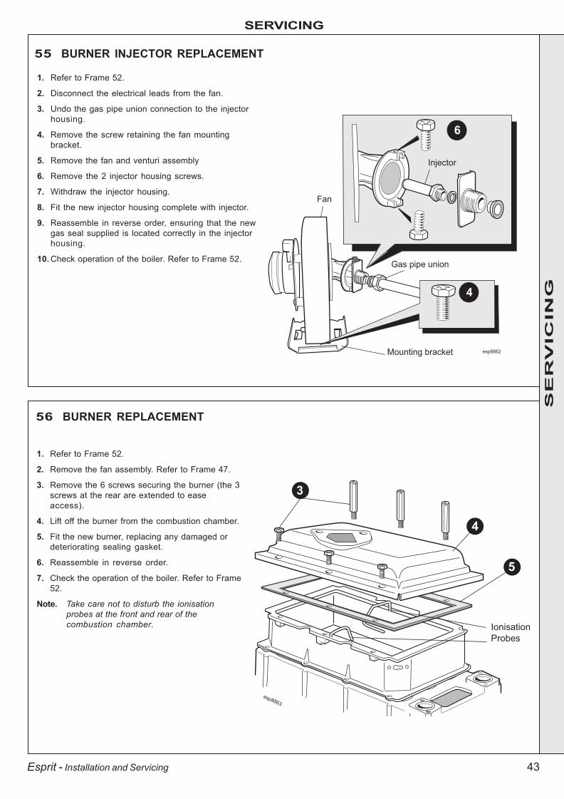
43
SERVICING
Esprit - Installation and Servicing
56 BURNER REPLACEMENT
1. Refer to Frame 52.
2. Remove the fan assembly. Refer to Frame 47.
3. Remove the 6 screws securing the burner (the 3screws at the rear are extended to easeaccess).
4. Lift off the burner from the combustion chamber.
5. Fit the new burner, replacing any damaged ordeteriorating sealing gasket.
6. Reassemble in reverse order.
7. Check the operation of the boiler. Refer to Frame52.
Note. Take care not to disturb the ionisationprobes at the front and rear of thecombustion chamber.
55 BURNER INJECTOR REPLACEMENT
1. Refer to Frame 52.
2. Disconnect the electrical leads from the fan.
3. Undo the gas pipe union connection to the injectorhousing.
4. Remove the screw retaining the fan mountingbracket.
5. Remove the fan and venturi assembly
6. Remove the 2 injector housing screws.
7. Withdraw the injector housing.
8. Fit the new injector housing complete with injector.
9. Reassemble in reverse order, ensuring that the newgas seal supplied is located correctly in the injectorhousing.
10. Check operation of the boiler. Refer to Frame 52.
Mounting bracket
6
esp8862
4
Injector
Fan
Gas pipe union
esp8863
Ionisation
Probes
3
4
5
SE
RV
ICIN
G
203642-2.pmd 05/10/2007, 11:5543

44
SERVICING
Esprit - Installation and Servicing
esp8865
4
3
58 IGNITION ELECTRODE REPLACEMENT
1. Refer to Frame 52.
2. Unplug the ignition lead from theelectrode.
3. Remove the earth lead from the ignitionelectrode.
4. Remove the remaining screw holding theignition electrode to the combustionchamber.
5. Remove the electrode.
6. Fit the new ignition electrode, using thenew gasket supplied. Check dimensionsas shown.
7. Reassemble in reverse order, and checkthat no damage to the combustionchamber insulation has occurred duringthe electrode replacement.
8. Check the operation of the boiler. Refer toFrame 52.
57 CONTROL THERMISTOR, RETURN THERMISTOR & OVERHEAT ‘STAT REPLACEMENT(Note. Refer to Frame 39 for locations)
1. Refer to Frame 52.
2. Unclip the thermistor / thermostat from the flow / returnpipe and withdraw it from the controls compartment.
3. Disconnect the electrical leads from the thermistor /thermostat.
4. Reconnect the electrical leads to the replacement partand reassemble in reverse order, ensuring that thespring clip is securely on the pipe.
5. Check the operation of the boiler. Refer to Frame 52.
Control Thermistor
Return ThermistorOverheat Thermostat
SE
RV
ICIN
G
203642-2.pmd 05/10/2007, 11:5544

45
SERVICING
Esprit - Installation and Servicing
esp8864
3
59 FLAME DETECTION ELECTRODE REPLACEMENT
1. Refer to Frame 52.
2. Unplug the flame detection lead from the electrode.
3. Remove the 2 screws holding the flame detectionelectrode to the combustion chamber.
4. Remove the electrode.
60 SPARK GENERATOR REPLACEMENT
1. Refer to Frame 52.2. Disconnect the leads from the spark
generator and bracket.3. Remove the M5 screw securing the spark
generator bracket to the flue casting.4. Remove the 2 M4 screws securing the
spark generator to the bracket.5. Fit the new spark generator and re-
assemble in reverse order.6. Check operation of the boiler. Refer to
Frame 52.
esp8802
2
3
2
2
4
5. Fit the new flame detection electrode, using the newgasket supplied. Check dimensions as shown.
6. Reassemble in reverse order, and check that no damageto the combustion chamber insulation has occurredduring the electrode replacement.
7. Check the operation of the boiler. Refer to Frame 52.
SE
RV
ICIN
G
203642-2.pmd 05/10/2007, 11:5545

46
SERVICING
Esprit - Installation and Servicing
61 GAS CONTROL VALVE REPLACEMENT
1. Refer to Frame 52.2. Swing the control box down into the servicing position.
Refer to Frame 46.3. Unplug the electrical lead connection from the gas
control valve and disconnect the earth wire.4. Undo the gas inlet pipe union at the gas service cock.5. Undo the union nut on the outlet of the gas control valve.6. Remove the back nut retaining the valve to the bottom
panel and withdraw the valve upwards.7. Fit the new gas control valve.8. Check operation of the boiler. Refer to Frame 52.
62 DIVERTER VALVE ACTUATOR REPLACEMENT
1. Refer to Frame 52.
2. Swing the control box down into theservicing position. Refer to Frame 46.
3. Remove the electrical connection.
4. Using a suitable tool pull out the retainingclip and lift the diverter head from thebrass body.
5. Fit new actuator head and reassemble inreverse order.
6. Check operation of the boiler. Refer toFrame 52.
4
6
4
5
3
3
SE
RV
ICIN
G
203642-2.pmd 05/10/2007, 11:5546

47
SERVICING
Esprit - Installation and Servicing
Rear
Front
Combustion
chamber
LH Side
RH Side
esp8866
5
4
6
8
63 COMBUSTION CHAMBER INSULATION REPLACEMENT
The insulation boards used in the combustion chamber ofthis product are made of high temperature glass fibres with abinder of organic and inorganic materials.
Ideal Stelrad Group recommend that, for your own comfortand safety and to comply with good working practice, theprocedure described below is followed:
1. Refer to Frame 52.
2. Remove the fan / venturi assembly. Refer to Frame 47.
3. Remove the burner. Refer to Frame 48.
4. Remove the ignition electrode. Refer to Frame 58.
5. Remove the flame detection electrode. Refer to Frame 59.
6. Remove the front and rear ionisation probes.
Prior to removal of the board the following protectiveequipment should be worn:
Face mask supplied with the spare part.
Gloves supplied with the spare part.
7. Damp down the combustion chamber area containing theinsulation boards.
8. Remove the split pin and washer from the RHS of thecombustion chamber.
9. Remove the insulation boards. The replacement boardsare supplied in a plastic bag. This bag should be retainedand the discarded boards should now be placed into it.
10. Sweep any dampened particles and place in the plasticbag.
11. Fit new insulation boards.Note.
The boards are designed to be interlocking and should befitted as shown.
12. Fit the new split pin and washer in the RHS of thechamber.
13. Remove the gloves and face mask and place them in theplastic bag.
14. Wash your hands and any areas of skin which may havecome into contact with any of the particles from theinsulation board.
Note. Seal the plastic bag and dispose of it and its contentsinto a commercial tip.
15. Reassemble in reverse order, remembering to re-fit theionisation probes first.
16. Check operation of the boiler. Refer to Frame 52.
Fit insulation in the following order:
1. Rear.
2. Left Hand Side.
3. Front.
4. Right Hand Side.
SE
RV
ICIN
G
203642-2.pmd 05/10/2007, 11:5547

48
SERVICING
Esprit - Installation and Servicing
64 CONDENSATE TRAP/SIPHON REPLACEMENT
1. Refer to Frame 52.
2. Swing the control box down into the servicing position.Refer to Frame 46.
3. Pull off the rubber top pipe.
4. Undo the siphon plastic union connection.
65 DHW THERMISTOR REPLACEMENT
1. Refer to Frames 52 & 72 for draining the appliance.
2. Swing the control box into the servicing position. Referto Frame 46.
3. Drain the DHW circuit. Refer to Frame 72.
4. Unscrew the knurled retaining nut.
3
5. Remove the backnut retaining the siphon to the bottompanel.
6. Fit the new siphon in reverse order ensuring the siphonis full of water.
7. Check operation of the boiler. Refer to Frame 52.
5
5. Disconnect the in line electrical connection andwithdraw the thermistor.
6. Reassemble in reverse order.
7. Check operation of the boiler. Refer to Frame 52.
4
54
SE
RV
ICIN
G
203642-2.pmd 05/10/2007, 11:5548

49
SERVICING
Esprit - Installation and Servicing
67 MAINS, PREHEAT AND SUMMER SWITCH REPLACEMENT
66 PRIMARY PCB REPLACEMENT
6
esp8849
5
4
3
1. Refer to Frame 52.
2. Swing the control box down into the servicingposition. Refer to Frame 46.
3. Remove the two screws retaining the control box lid.
4. Unclip the controls box lid and remove.
5. Push the switch/switches to be replaced out from therear.
6. Disconnect electrical leads from switches.
7. Fit new switch, ensuring that the electrical leads arereplaced on the correct terminals (refer to Frames 36and 37) and the key on the switch is correctly alignedwith the slot in the plastic moulding.
8. Reassemble in reverse order.
9. Check operation of boiler. Refer to Frame 52.
esp8853
5
6
4
3
1. Refer to Frame 52.
2. Swing the control box down into the servicing position.Refer to Frame 46.
3. Remove the two screws retaining the control box lid.
4. Unclip the controls box lid and remove.
5. Remove all of the terminal connections to the primaryPCB.
6. Unclip the two plastic posts retaining the primary PCB andremove.
7. Fit the new primary PCB.
8. Reassemble in reverse order.
9. Check the operation of the boiler. Refer to Frame 52.
SE
RV
ICIN
G
203642-2.pmd 05/10/2007, 11:5549

50
SERVICING
Esprit - Installation and Servicing
68 USER CONTROL PCB
69 PRESSURE GAUGE REPLACEMENT
1. Refer to Frame 52.2. Drain the boiler. Refer to Frame 72.3. Swing the control box into the servicing position. Refer to
Frame 46.4. Unscrew the pressure gauge connection.5. Remove the 2 screws retaining the controls box lid.6. Remove the controls box lid by unclipping the plastic clips.7. Unclip the pressure gauge head from the plastic control
box surround.8. Fit the new pressure gauge.9. Re-assemble the boiler in reverse order.10. Check the operation of the boiler. Refer to Frame 52.
4
esp8855
4
56
3
9
1. Refer to Frame 52.
2. Swing the control box into the servicingposition. Refer to Frame 46.
3. Remove the 2 screws retaining the controlbox lid.
4. Remove the Controls box lid by unclippingthe plastic clips.
5. Unclip and remove the primary PCB. Referto Frame 67.
6. Remove the plate interface shield.
7. Attach the earth strap supplied to wrist andclip on to main boiler chassis.
8. Remove the electrical connection from theback of the user control PCB.
9. Remove the three screws retaining theuser control PCB and replace.
10. Re assemble the boiler in reverse order.11. Check the operation of the boiler. Refer to
Frame 52.
esp8867
5
6
7
SE
RV
ICIN
G
203642-2.pmd 05/10/2007, 11:5550

51
SERVICING
Esprit - Installation and Servicing
esp8936
Air vent
Plug
Fan6
5
70 SAFETY RELIEF VALVE REPLACEMENT1. Refer to Frame 52.
2. Drain the boiler CH circuit. Refer to Frame72.
3. Unscrew the nut securing the pipe to thepump outlet.
4. Disconnect the electrical connections.
5. Withdraw the pump clip.
6. Remove screw securing pump throughbottom panel.
7. Pull pump forward to disengage frommanifold and remove.
8. Unscrew the discharge pipe union nut.
9. Unscrew the safety valve retaining screw.
10. Pull the safety valve upwards to remove.
11. Fit the new safety valve and tighten thesecuring screw.
12. Reassemble in reverse order.
13. Refill the boiler. Refer to Frame 32.
14. Check operation of the boiler. Refer toFrame 52.
71 AUTOMATIC AIR VENT REPLACEMENT
1. Refer to Frame 52.2. Drain the boiler. Refer to frame 72.3. Remove the turret from the boiler. Refer to
frame 24.4. Release the silicon tubing from the sample
point.5. Release the electrical connections from the
spark generator.6. Remove the M5 x 10 screw retaining the top
flue manifold casting.7. Remove the top flue manifold casting.8. Remove the fan from the boiler. Refer to
Frame 47.9. Remove the burner from the heat exchanger.
Refer to Frame 48.10. Unscrew the air vent from its heat exchanger
mount and replace.11. Re assemble the boiler in reverse order.
12. Refill the boiler. Refer to frame 32. Check forleaks around the new air vent joint.
13. Check the operation of the boiler. Refer to frame 52.
8
9
10
34
5
6
SE
RV
ICIN
G
203642-2.pmd 05/10/2007, 11:5551
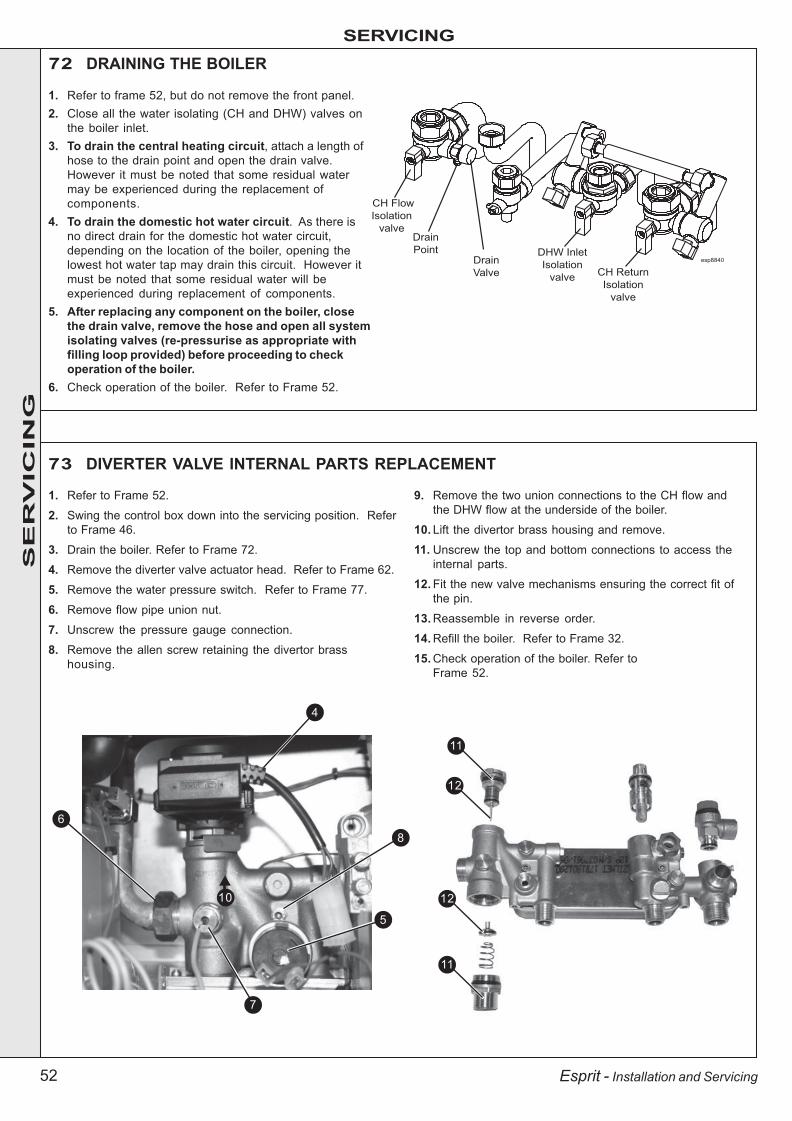
52
SERVICING
Esprit - Installation and Servicing
72 DRAINING THE BOILER
1. Refer to frame 52, but do not remove the front panel.2. Close all the water isolating (CH and DHW) valves on
the boiler inlet.3. To drain the central heating circuit, attach a length of
hose to the drain point and open the drain valve.However it must be noted that some residual watermay be experienced during the replacement ofcomponents.
4. To drain the domestic hot water circuit. As there isno direct drain for the domestic hot water circuit,depending on the location of the boiler, opening thelowest hot water tap may drain this circuit. However itmust be noted that some residual water will beexperienced during replacement of components.
5. After replacing any component on the boiler, closethe drain valve, remove the hose and open all systemisolating valves (re-pressurise as appropriate withfilling loop provided) before proceeding to checkoperation of the boiler.
6. Check operation of the boiler. Refer to Frame 52.
73 DIVERTER VALVE INTERNAL PARTS REPLACEMENT
1. Refer to Frame 52.
2. Swing the control box down into the servicing position. Referto Frame 46.
3. Drain the boiler. Refer to Frame 72.
4. Remove the diverter valve actuator head. Refer to Frame 62.
5. Remove the water pressure switch. Refer to Frame 77.
6. Remove flow pipe union nut.
7. Unscrew the pressure gauge connection.
8. Remove the allen screw retaining the divertor brasshousing.
CH Flow
Isolation
valveDrain
PointDrain
Valve
DHW Inlet
Isolation
valveCH Return
Isolation
valve
esp8840
4
9. Remove the two union connections to the CH flow andthe DHW flow at the underside of the boiler.
10. Lift the divertor brass housing and remove.
11. Unscrew the top and bottom connections to access theinternal parts.
12. Fit the new valve mechanisms ensuring the correct fit ofthe pin.
13. Reassemble in reverse order.
14. Refill the boiler. Refer to Frame 32.
15. Check operation of the boiler. Refer toFrame 52.
68
5
11
12
12
11
10
7
SE
RV
ICIN
G
203642-2.pmd 05/10/2007, 11:5552

53
SERVICING
Esprit - Installation and Servicing
74 DHW FLOW SWITCH REPLACEMENT
1. Refer to frame 52.2. Swing the control box down into the servicing
position. Refer to Frame 46.3. Unplug the electrical connection.4. Carefully pull the switch upwards to
disengage.5. Fit the new switch and replace the electrical
plug connection.6. Re-assemble in reverse order7. Check operation of the boiler. Refer to
Frame 52.
5
75 DHW FILTER REPLACEMENT
1. Refer to frame 52.2. Swing the control box down into the
servicing position. Refer to Frame 46.3. Drain the boiler. Refer to Frame 72.4. Remove the DHW flow switch. Refer to
Frame 74.5. Unscrew the DHW filter housing from the
main brass body.6. Remove and fit new filter.7. Re-assemble in reverse order.8. Refill the boiler. Refer to Frame 32.9. Check operation of the boiler. Refer to
Frame 52.
5
3
6
SE
RV
ICIN
G
4
203642-2.pmd 05/10/2007, 11:5553

54
SERVICING
Esprit - Installation and Servicing
76 FLOW LIMITER REPLACEMENT
77 WATER PRESSURE SWITCH REPLACEMENT1. Refer to frame 52.2. Swing the control box down into the servicing
position. Refer to Frame 46.3. Drain the boiler CH circuit. Refer to Frame 72.4. Pull off the two electrical connections.5. Unscrew the water pressure switch.6. Re-assemble in reverse order.7. Refill the boiler. Refer to Frame 32.8. Check operation of the boiler. Refer to Frame 52.
5
4
1. Refer to frame 52.2. Isolate the mains cold water supply to
the boiler.3. Drain the boiler DHW circuit. Refer to
Frame 72.4. Unscrew the three union connections at
the DHW isolating valve and remove thevalve.
5. Remove the circlip retaining the flowlimiter.
6. Using a suitable tool, pull the flowlimiter from the valve body.
7. Fit the new flow limiter and reassemblein reverse order.
8. Refill the boiler. Refer to Frame 32.9. Check operation of the boiler. Refer to
Frame 52.
5
64
SE
RV
ICIN
G
203642-2.pmd 05/10/2007, 11:5554

55
SERVICING
Esprit - Installation and Servicing
79 PUMP HEAD REPLACEMENT
1. Refer to Frame 52.
2. Drain the boiler CH circuit. Refer to Frame 72.
3. Swing the control box down into the servicingposition. Refer to Frame 46.
4. Disconnect the electrical lead from the pump.
5. Remove the 4 Allen screws retaining the pumphead.
6. Remove the pump head.
7. Fit the new pump head.
8. Reassemble in reverse order.
9. Refill the boiler. Refer to Frame 32.
10. Check operation of the boiler. Refer to Frame 52.
78 DHW PLATE HEAT EXCHANGER REPLACEMENT
1. Refer to Frame 52.
2. Swing the control box down into theservicing position. Refer to Frame 46.
3. Drain the boiler. Refer to Frame 72.
4. Remove divertor valve actuator. Refer toFrame 62.
5. Remove gas valve. Refer to Frame 61.
6. Remove the 2 allen screws securing theplate heat exchanger to the brasshousings.
7. Manoeuvre the plate heat exchanger out ofthe boiler.
8. Fit the new plate heat exchanger, using thenew o-rings supplied.
9. Reassemble in reverse order.
10. Refill the boiler. Refer to Frame 32.
11. Check operation of the boiler. Refer toFrame 52.
66 7
54
4
SE
RV
ICIN
G
203642-2.pmd 05/10/2007, 11:5555

56
SERVICING
Esprit - Installation and Servicing
Refer also to Frame 8 - 'Boiler Exploded View'.IMPORTANTBefore starting the removal procedure, protect the gas andelectrical controls with a waterproof sheet or plastic bag.
1. Refer to Frame 52.
2. Drain the boiler. Refer to Frame 72.
3. Swing the control box down into the servicing position.Refer to Frame 46.
4. Remove the fan / venturi assembly and place on oneside. Refer to Frame 47.
5. Remove the burner and place on one side. Refer toFrame 56.
6. Remove the ignition and detection electrodes. Refer toFrames 58 & 59.
7. Remove the spark generator. Refer to Frame 60.
8. Release the flue from the turret. Refer to Frame 24.
9. Remove the turret from the boiler. Refer to Frame 24.
10. Release the silicone tubing from the sampling point.
11. Release the electrical connection to the dry firethermistor.
12. Remove the M5 x 10 screw retaining the top flue manifoldcasting.
13. Remove the top casting of the flue manifold from theappliance.
80 HEAT ENGINE REPLACEMENT14. Remove the automatic air vent. Refer to Frame 71.
15. Undo the M5 x 12 screws securing the bottom fluemanifold casting and remove.
16. Remove the M5 screw and remove the return pipesecuring bracket by sliding forwards.
17. Remove the overheat thermostat and the controlthermistor. Refer to Frame 57.
18. Unscrew the brass union connection to release the flowpipe.
19. Remove the condensate trap/ siphon. Refer to Frame 64.
20. Loosen the 2 bottom M5 screws securing the inter panel tothe back panel and remove the 2 upper M5 screws.
21. Slide the heat exchanger and inter panel assemblyupward to disengage and remove from the casing,complete with the flow pipe.
22. Remove the 2 M6 countersunk screws, remove the interpanel and transfer to the new heat exchanger.
23. Remove the M5 screw and remove the flow pipe securingbracket.
24. Remove the flow pipe and transfer to the new heatexchanger.
25. Reassemble in reverse order, replacing gaskets or sealsif any sign of damage or deterioration is evident.
Note.The heat exchanger is supplied with new combustionchamber insulation boards. These should be fitted (referto Frame 63 before the burner and fan / venturiassembly and before the ignition and detectionelectrodes are replaced).
26. Refill the boiler. Refer to Frame 32.
27. Check operation of the boiler. Refer to Frame 52.
esp
88
69
2012 10
11 14
15
15
16
23
22
18
SE
RV
ICIN
G
203642-2.pmd 05/10/2007, 11:5556
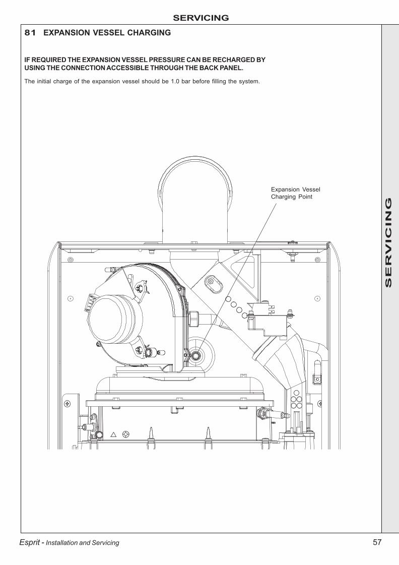
57
SERVICING
Esprit - Installation and Servicing
81 EXPANSION VESSEL CHARGING
IF REQUIRED THE EXPANSION VESSEL PRESSURE CAN BE RECHARGED BYUSING THE CONNECTION ACCESSIBLE THROUGH THE BACK PANEL.
The initial charge of the expansion vessel should be 1.0 bar before filling the system.
Expansion VesselCharging Point
SE
RV
ICIN
G
203642-2.pmd 05/10/2007, 11:5557
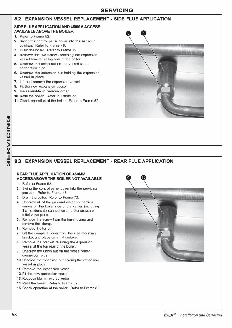
58
SERVICING
Esprit - Installation and Servicing
82 EXPANSION VESSEL REPLACEMENT - SIDE FLUE APPLICATIONSIDE FLUE APPLICATION AND 450MM ACCESSAVAILABLE ABOVE THE BOILER1. Refer to Frame 52.2. Swing the control panel down into the servicing
position. Refer to Frame 46.3. Drain the boiler. Refer to Frame 72.4. Remove the two screws retaining the expansion
vessel bracket at top rear of the boiler.5. Unscrew the union nut on the vessel water
connection pipe.6. Unscrew the extension nut holding the expansion
vessel in place7. Lift and remove the expansion vessel.8. Fit the new expansion vessel.9. Re-assemble in reverse order10. Refill the boiler. Refer to Frame 32.11. Check operation of the boiler. Refer to Frame 52.
REAR FLUE APPLICATION OR 450MMACCESS ABOVE THE BOILER NOT AVAILABLE1. Refer to Frame 52.2. Swing the control panel down into the servicing
position. Refer to Frame 46.3. Drain the boiler. Refer to Frame 72.4. Unscrew all of the gas and water connection
unions on the boiler side of the valves (includingthe condensate connection and the pressurerelief valve pipe).
5. Remove the screw from the turret clamp andremove the clamp.
6. Remove the turret.7. Lift the complete boiler from the wall mounting
bracket and place on a flat surface.8. Remove the bracket retaining the expansion
vessel at the top rear of the boiler.9. Unscrew the union nut on the vessel water
connection pipe.10. Unscrew the extension nut holding the expansion
vessel in place.11. Remove the expansion vessel.12. Fit the new expansion vessel.13. Reassemble in reverse order14. Refill the boiler. Refer to Frame 32.15. Check operation of the boiler. Refer to Frame 52.
65
109
83 EXPANSION VESSEL REPLACEMENT - REAR FLUE APPLICATION
SE
RV
ICIN
G
203642-2.pmd 05/10/2007, 11:5558

59Esprit - Installation and Servicing
203642-2.pmd 05/10/2007, 11:5559
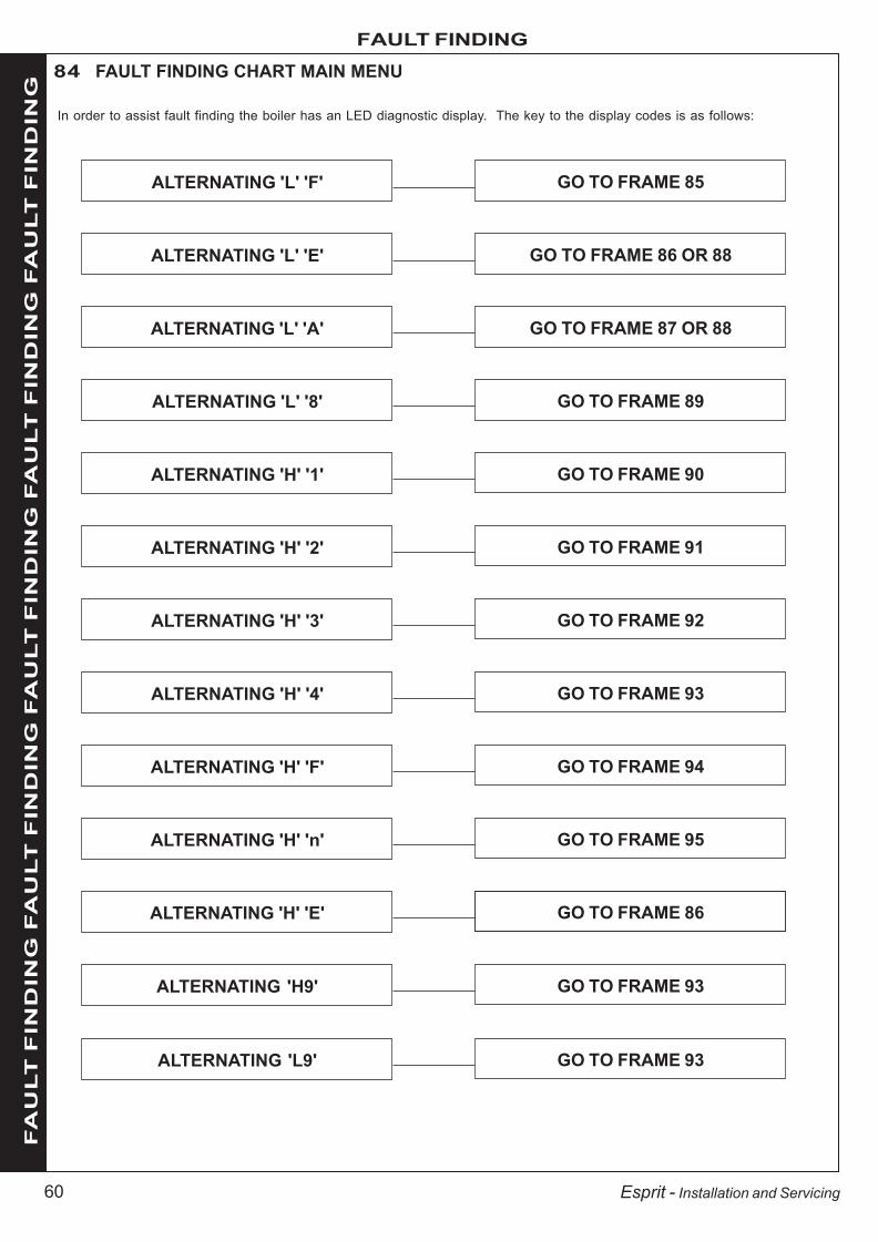
60
FAULT FINDINGF
AU
LT
FIN
DIN
G F
AU
LT
FIN
DIN
G F
AU
LT
FIN
DIN
G F
AU
LT
FIN
DIN
G F
AU
LT
FIN
DIN
G
Esprit - Installation and Servicing
84 FAULT FINDING CHART MAIN MENU
ALTERNATING 'L' 'F' GO TO FRAME 85
ALTERNATING 'L' 'E' GO TO FRAME 86 OR 88
ALTERNATING 'L' 'A' GO TO FRAME 87 OR 88
ALTERNATING 'L' '8' GO TO FRAME 89
ALTERNATING 'H' '1' GO TO FRAME 90
ALTERNATING 'H' '2' GO TO FRAME 91
ALTERNATING 'H' '3' GO TO FRAME 92
ALTERNATING 'H' '4' GO TO FRAME 93
ALTERNATING 'H' 'F' GO TO FRAME 94
In order to assist fault finding the boiler has an LED diagnostic display. The key to the display codes is as follows:
ALTERNATING 'H' 'n' GO TO FRAME 95
ALTERNATING 'H' 'E' GO TO FRAME 86
ALTERNATING 'H9' GO TO FRAME 93
ALTERNATING 'L9' GO TO FRAME 93
203642-2.pmd 05/10/2007, 11:5560

61
FAULT FINDING
FA
UL
T F
IND
ING
FA
UL
T F
IND
ING
FA
UL
T F
IND
ING
FA
UL
T F
IND
ING
FA
UL
T F
IND
ING
Esprit - Installation and Servicing
85 L.....F.....(FLAME DETECTION ERROR)
Check the ignition electrode and associated harnessfor: continuity, visual condition, position
(Refer to Frame 58).
Are these functioning correctly ?
Check gas valvewiring forcontinuity
YES
Check the detection electrode andassociated harness for:
continuity, visual condition, position(Refer to Frame 59).
Replace as necessary.
If the boiler reset button ispressed does the boiler ignite for
a short time then extinguish?
Is 200V DC supply availableat the gas valve ?
(see Note)
NO
YESYES
Is gas pressure available atthe boiler inlet ?
Replace PCB
Check gas supplyand rectify fault
Replace ignition electrode and associatedharness as necessary
NO
Replace gas valve
YES
NO
NO
86 L.....E..... or H.....E..... (PCB ERROR)
Note. Due to the wave form of the rectified voltage, the reading will vary depending on the type of meter used tomeasure the value (some may measure the possible peak voltage of 339V). In general terms a reading greaterthan 150V indicates that the correct voltage is supplied to the gas valve. As an alternative to a meter, a mainsvoltage checking device may be used. E.g. an electrical screwdriver or mains tester.
Check spark generator and associatedharness for continuity and visual condition.
(Refer to Frame 60).
Are these functioning correctly ? Replace sparkgenerator
YES
NO
Internal fault within the PCB
Replace PCB
Press and hold reset button for 2seconds. Does boiler operate
correctly?
Turn boiler off and wait for 5seconds. Turn boiler on.
Does boiler operate correctly?
NO
NO
YESOK
YESOK
Check syphonand condensatedrain pipework
for blockage
203642-2.pmd 05/10/2007, 11:5561

62
FAULT FINDINGF
AU
LT
FIN
DIN
G F
AU
LT
FIN
DIN
G F
AU
LT
FIN
DIN
G F
AU
LT
FIN
DIN
G F
AU
LT
FIN
DIN
G
Esprit - Installation and Servicing
Does the pump setting give a differentialacross the boiler in excess of 25 oC ?
Can the overheat condition be reset by pressingthe boiler reset button when the system is cold ?
Replace the system pumpSet CH control knob to maximum.If the overheat trips again measure the flow temp:
Over 90 oC Check control thermistor(Refer to Frame 90)
Under 90 oC Replace overheat 'stat
YES (also refer to Frame 88)
YES
Check that the pump is rotating freely.Is differential now below 25 oC ?
NO
NO
87 L.....A..... (OVERHEAT ERROR)
Fill and vent the system and open allisolation valves
YES
Is the boiler and CH system filled withwater and all isolation valves open ?
OK
NO YES
NOReplace overheat thermostat
89 L....8..... (FAN ERROR)
Is nominal 330 V DC present acrossred and blue at the fan connector as
reset button is pressed?
Replace fanYES
NO
Replace harness
Replace PCB
YES Is 14V DC present acrossyellow and pink at the fan
connector?
Check wiring harness for continuity.Is there continuity? NO
YESNO
88 L.....E..... OR L.....A..... (WATER PRESSURE SWITCH)
Is 230V available across the water pressureswitch electrical leads
Can the overheat condition be reset by pressingthe boiler reset button when the system is cold ?
YES (also refer to Frame 86)
NO
Replace PCB
NO Fill and vent the system and open allisolation valves
NO
Is the boiler and CH system filled with waterwith a minimum pressure of 1.0 bar (cold)
and all isolation valves open?
YES
Replace water pressure switch
Note.LE occurs when boiler is cold.LA occurs when boiler is hot.
YESOK
Note. With V9 Primary Control PCB, overheat LA/HA or H9/L9 whenreset will display 3 horizontal lines and will not attempt to refire untilthe temperature in the heat exchanger drops below 50oC.
Note. With V9 Primary Control PCB, overheat LA/HA or H9/L9 whenreset will display 3 horizontal lines and will not attempt to refire untilthe temperature in the heat exchanger drops below 50oC.
203642-2.pmd 05/10/2007, 11:5562

63
FAULT FINDING
FA
UL
T F
IND
ING
FA
UL
T F
IND
ING
FA
UL
T F
IND
ING
FA
UL
T F
IND
ING
FA
UL
T F
IND
ING
Esprit - Installation and Servicing
92 H.....3..... (DHW THERMISTOR ERROR)
YES
Is there continuity between the PCB and the thermistor ?
Remove the boiler DHW thermistor from the plateheat exchanger and disconnect thermistor wires.
Are the thermistor values correct ? Replace the thermistorNO
NO
YES Replace PCB
Check and replace wiring as necessary
Check resistance using a suitable multimeterconnected across the thermistor’s terminal pinsAt 25 oC expect 9,700 - 10,300 OhmsAt 60 oC expect 2,400 - 2,600 OhmsAt 85 oC expect 1,000 - 1,100 Ohms
91 H.....2..... (CONTROL THERMISTOR [RETURN] ERROR)
YES
Is there continuity between the PCB and the thermistor ?
Remove the boiler return thermistor from the CH return pipe.
Are the thermistor values correct ? Replace the thermistorNO
NO
YES Replace PCB
Check and replace wiring as necessary
Check resistance using a suitable multimeterconnected across the thermistor’s terminal pinsAt 25 oC expect 9,700 - 10,300 OhmsAt 60 oC expect 2,400 - 2,600 OhmsAt 85 oC expect 1,000 - 1,100 Ohms
90 H.....1..... (CONTROL THERMISTOR [FLOW] ERROR)
YES
Is there continuity between the PCB and the thermistor ?
Remove the boiler control thermistor from the CHflow pipe and disconnect thermistor wires.
Are the thermistor values correct ? Replace the thermistorNO
NO
YES Replace PCB
Check and replace wiring as necessary
Check resistance using a suitable multimeterconnected across the thermistor’s terminal pinsAt 25 oC expect 9,700 - 10,300 OhmsAt 60 oC expect 2,400 - 2,600 OhmsAt 85 oC expect 1,000 - 1,100 Ohms
203642-2.pmd 05/10/2007, 11:5563

64
FAULT FINDINGF
AU
LT
FIN
DIN
G F
AU
LT
FIN
DIN
G F
AU
LT
FIN
DIN
G F
AU
LT
FIN
DIN
G F
AU
LT
FIN
DIN
G
Esprit - Installation and Servicing
93 H.....4.... (DRY FIRE THERMISTOR ERROR)
Check wiring for continuity from thePCB to the dry fire thermistor
Can the fault condition be reset by switching offthe mains supply to the boiler ?
Is the system filled and vented andall isolation valves open ?
Is the pump operating correctly?Ensure flow through system.
NO
Are thermistor values correct ?
Replace PCB Replace thermistor
Fill and vent thesystem and open all
isolating valves
YES
Are thermistor values correct ?
Inspect heatexchanger for
blockage or damagein the flueways.
Clean or replace asnecessary
Replace thermistorNO
95 H......n..... (PHASE REVERSAL ERROR)
Check wiring to the boiler forreversed live and neutral
YES NO
YES NO
94 H......F..... (FLAME DETECTION ERROR)
Replace flame detection electrode
Is there continuity between the 2 terminal pins ?NO
YES
Remove flame detection electrode terminal from PCB
Replace PCB
Check resistance using a suitable multimeterconnected across the thermistor’s terminal pins
At 25 oC expect 9,700 - 10,300 Ohms
At 60 oC expect 2,400 - 2,600 Ohms
At 85 oC expect 1,000 - 1,100 Ohms
Check resistance using a suitable multimeterconnected across the dry fire thermistor’s
terminal pins
At 25 oC expect 9,700 - 10,300 Ohms
At 60 oC expect 2,400 - 2,600 Ohms
At 85 oC expect 1,000 - 1,100 Ohms
H9/L9 (HEAT EXCHANGER OVERHEAT)
Note. With V9 Primary Control PCB, overheat LA/HAor H9/L9 when reset will display 3 horizontal lines andwill not attempt to refire until the temperature in theheat exchanger drops below 50oC.
203642-2.pmd 05/10/2007, 11:5564

65
SHORT LIST OF PARTS
Esprit - Installation and Servicing
Key No. G.C. Part No. Description Product Number
1. Front Casing Panel 174792 2. Front Casing Door 174783
8. E67489 Burner 1709059. H07660 Combustion Chamber Insulation 17352211. E67492 Injector & Housing 24, 30 17090811. H07770 Injector & Housing 35 17352213. E85097 Fan 24, 30 17262513. H07771 Fan 35 17352514. Automatic Air Vent Kit (Heat Exchanger) 17266816. Gas Valve 17478920. Control Thermistor (Flow / Return) 17479021. Overheat Thermostat 17479122. H07664 Ignition Electrode 17352823. H07665 Flame sensing electrode 17352924. Kit – Trap and Seal 17424425. User Control PCB 17497526. PCB Primary Controls 17448627. Mains Switch 17479628. Pre-Heat & Winter/Summer Switch 17479730. Turret Gasket 17480631. H07731 Spark Generator 17353832. H07790 Ignition Lead 17351035. Pressure Relief Valve Kit 17481136. Expansion Vessel 17481238. Pressure Gauge 17389239. DHW Thermistor 17484940. Diverter Valve Head 17481341. Diverter Valve Cartridge 17481443. Pump 17481745. Plate Heat Exchanger 24 17482045. Plate Heat Exchanger 30 17482145. Plate Heat Exchanger 35 17482246. Dry Fire Thermistor 17408747. Water Pressure Switch 17482448. Reed Switch 17481949. REED Switch Cartridge & Filter 17484450. Air Vent (Pump) 17489451. Filling Loop 17482559. Detection Lead 17478769. Control Box Clip Kit 17482686. E78200 Burner Earth Pin 17184587. Heat Engine Gasket Kit 17487790. E67519 Fuse - PCB Kit 170931
When ordering spares please quote:
1. Boiler model
2. Appliance G.C. No.
3. Description.
4. Quantity.
5. Product number.
The following are parts commonly required due to damage orexpendability. Their failure or absence is likely to affect safety orperformance of this appliance.
The list is extracted from the British Gas List of Parts, whichcontains all available spare parts.
The full list is held by British Gas Services, Ideal Stelrad Groupdistributors and merchants.
When replacing any part on this appliance use only spare parts that you can be assured conform to the safety and performancespecification that we require. Do not use reconditioned or copy parts that have not been clearly authorised by Ideal Boilers.
203642-2.pmd 05/10/2007, 11:5565

66
SHORT LIST OF PARTS
Esprit - Installation and Servicing
96 SHORT LIST
16
24
40
Esp8893
8
14
9
11
13
22
26
23
90
31
87
21
20
27 & 28
36
30
35
39
32
46
59
38
51
45
48
49
41
47
43
50
1
2
25
6986
203642-2.pmd 05/10/2007, 11:5566

67
SHORT LIST OF PARTS
Esprit - Installation and Servicing
Ecl 1598
97 CONTROLS ASSEMBLY
98 BURNER ASSEMBLY
8. Burner assembly with screws and gasket.
67
66
25
69
68
70
272838
64
26
65
Esp8894
25. User Control PCB
26. PCB Primary Control
27. Mains Switch
28. Pre-heat and Winter/Summer Switch
38. Pressure Gauge
65. Control Box Lid
66. Mains Cover
67. Controls Cover
68. Potentiometer Knob
69. Control Box Clip
70. Programmer Insert
203642-2.pmd 05/10/2007, 11:5567

68
NOTES
Esprit - Installation and Servicing
203642-2.pmd 05/10/2007, 11:5568

INSTALLER NOTIFICATION GUIDELINES
IT IS A REQUIREMENT OF CORGI MEMBERSHIP TO REGISTER EVERY GAS APPLIANCE
In addition a change to Building Regulations (England and Wales) requires the installer to notify
when installing a heating appliance, as from 1st April 2005.
Competent Person's
SELF CERTIFICATION SCHEME BUILDING CONTROL
Install and commission
this appliance to
manufacturers' instructions
Complete the
Benchmark Checklist
Choose
Buildings Regulations
notification route
Contact your relevant
Local Authority
Building Control (LABC) who
will arrange an inspection
or contact a government
approved inspector
LABC will record the data
and will issue a
certificate of compliance
If you notify via CORGI Scheme,
CORGI will then notify the
relevant Local Authority Building
Control (LABC) scheme
on members behalf
Scheme members only:
Call CORGI on 0870 88 88 777
or log onto:
www.corgi-notify.com
within 10 days
You must ensure that the
notification number
issued by CORGI is written
onto the Benchmark Checklist
CORGI will record the data and
will send a certificate of
compliance to the property
IT IS A CONDITION OF THE
MANUFACTURERS WARRANTY
THAT THE BENCHMARK
COMMISSIONING CHECKLIST IS
FULLY COMPLETED AND LEFT
WITH THE APPLIANCE
203642-2.pmd 05/10/2007, 11:5569

CONTROLS To comply with the Building Regulations, each section must have a tick in one or other of the boxes
TIME & TEMPERATURE CONTROL TO HEATING ROOM T/STAT & PROGRAMMER/TIMER PROGRAMMABLE ROOMSTAT
TIME & TEMPERATURE CONTROL TO HOT WATER CYLINDER T/STAT & PROGRAMMER/TIMER COMBI BOILER
HEATING ZONE VALVES FITTED NOT REQUIRED
HOT WATER ZONE VALVES FITTED NOT REQUIRED
THERMOSTATIC RADIATOR VALVES FITTED
AUTOMATIC BYPASS TO SYSTEM FITTED NOT REQUIRED
FOR ALL BOILERS CONFIRM THE FOLLOWING
THE SYSTEM HAS BEEN FLUSHED IN ACCORDANCE WITH THE BOILER MANUFACTURERÕS INSTRUCTIONS?
THE SYSTEM CLEANER USED
THE INHIBITOR USED
FOR THE CENTRAL HEATING MODE, MEASURE & RECORD
GAS RATE ft3/hr
BURNER OPERATING PRESSURE (IF APPLICABLE) mbar
CENTRAL HEATING FLOW TEMPERATUREoC
CENTRAL HEATING RETURN TEMPERATUREoC
FOR COMBINATION BOILERS ONLY
HAS A WATER SCALE REDUCER BEEN FITTED? YES NO
WHAT TYPE OF SCALE REDUCER HAS BEEN FITTED?
FOR THE DOMESTIC HOT WATER MODE, MEASURE & RECORD
GAS RATE ft3/hr
MAXIMUM BURNER OPERATING PRESSURE (IF APPLICABLE) mbar
COLD WATER INLET TEMPERATUREoC
HOT WATER OUTLET TEMPERATUREoC
WATER FLOW RATE lts/min
FOR CONDENSING BOILERS ONLY CONFIRM THE FOLLOWING
THE CONDENSATE DRAIN HAS BEEN INSTALLED IN ACCORDANCE WITH
THE MANUFACTURER'S INSTRUCTIONS? YES
FOR ALL INSTALLATIONS CONFIRM THE FOLLOWING
THE HEATING AND HOT WATER SYSTEM COMPLIES
WITH CURRENT BUILDING REGULATIONS
THE APPLIANCE AND ASSOCIATED EQUIPMENT HAS BEEN INSTALLED AND COMMISSIONED
IN ACCORDANCE WITH THE MANUFACTURER'S INSTRUCTIONS
IF REQUIRED BY THE MANUFACTURER, HAVE YOU RECORDED A CO/CO2 RATIO READING? N/A YES CO/CO2 RATIO
THE OPERATION OF THE APPLIANCE AND SYSTEM
CONTROLS HAVE BEEN DEMONSTRATED TO THE CUSTOMER
THE MANUFACTURER'S LITERATURE HAS BEEN LEFT WITH THE CUSTOMER
m3/hr
m3/hr
COMMISSIONING ENG'S NAME PRINT CORGI ID No.
SIGN DATE
BOILER SERIAL No. NOTIFICATION No.
BENCHMARK No.
GAS BOILER COMMISSIONING CHECKLISTC O L L E C T I V E M A R K
N/A
N/A
203642-2.pmd 05/10/2007, 11:5570

SERVICE INTERVAL RECORD
It is recommended that your heating system is serviced regularly
and that you complete the appropriate Service Interval Record Below.
Service Provider. Before completing the appropriate Service Interval Record below, please ensure you have carried out the service
as described in the boiler manufacturer's instructions. Always use the manufacturer's specified spare part when replacing all controls
SERVICE 1 DATE
ENGINEER NAME
COMPANY NAME
TEL No.
CORGI ID CARD SERIAL No.
COMMENTS
SIGNATURE
SERVICE 2 DATE
ENGINEER NAME
COMPANY NAME
TEL No.
CORGI ID CARD SERIAL No.
COMMENTS
SIGNATURE
SERVICE 3 DATE
ENGINEER NAME
COMPANY NAME
TEL No.
CORGI ID CARD SERIAL No.
COMMENTS
SIGNATURE
SERVICE 4 DATE
ENGINEER NAME
COMPANY NAME
TEL No.
CORGI ID CARD SERIAL No.
COMMENTS
SIGNATURE
SERVICE 5 DATE
ENGINEER NAME
COMPANY NAME
TEL No.
CORGI ID CARD SERIAL No.
COMMENTS
SIGNATURE
SERVICE 6 DATE
ENGINEER NAME
COMPANY NAME
TEL No.
CORGI ID CARD SERIAL No.
COMMENTS
SIGNATURE
SERVICE 7 DATE
ENGINEER NAME
COMPANY NAME
TEL No.
CORGI ID CARD SERIAL No.
COMMENTS
SIGNATURE
SERVICE 8 DATE
ENGINEER NAME
COMPANY NAME
TEL No.
CORGI ID CARD SERIAL No.
COMMENTS
SIGNATURE
SERVICE 9 DATE
ENGINEER NAME
COMPANY NAME
TEL No.
CORGI ID CARD SERIAL No.
COMMENTS
SIGNATURE
SERVICE 10 DATE
ENGINEER NAME
COMPANY NAME
TEL No.
CORGI ID CARD SERIAL No.
COMMENTS
SIGNATURE
203642-2.pmd 05/10/2007, 11:5571

Ideal Boilers, P.O. Box 103, National Ave, Kingston upon Hull,HU5 4JN. Telephone: 01482 492 251 Fax: 01482 448 858.Registration No. London 322 137.
Technical Training
Ideal Stelrad Group pursues a policy of continuingimprovement in the design and performance of its products. Theright is therefore reserved to vary specification without notice.
The Ideal Boilers Technical Training Centre offers a seriesof first class training courses for domestic, commercial andindustrial heating installers, engineers and systemspecifiers.For details of courses please ring: ............. 01482 498 432
CERTIFIED PRODUCTManufactured under a BS EN ISO 9001:2000 Quality System accepted by BSI
The code of practice for the installation,commissioning & servicing of central heating systems
Ideal Installer/Technical Helpline: 01482 498 673www.idealboilers.com
203642-2.pmd 05/10/2007, 11:5572

users guide
ideal espritYour Ideal users guide
When replacing any part on this appliance use only spare parts that you can be assured conform to the safety and performance specification that we require. Do not use reconditioned or copy parts that have not been clearly authorised by Ideal Boilers.
HE24, HE30, HE35For installation guide see reverse of book
203642-1.pmd 07/09/2007, 10:1173

2 Esprit - User’s
Children should be supervised to ensure that they do not play with theappliance.
In cases of repeated or continuous shutdown a CORGI registered installer orin IE a competent person should be called to investigate and rectify thecondition causing this and carry out an operational test. Only themanufacturers original parts should be used for replacement.
Minimum ClearancesClearances of 160mm above, 200mm below, 5mm at the sides and450mm at the front of the boiler casing must be allowed for servicing.The minimum front and bottom clearance allowed when built into a cupboardis 5mm.
To light the boiler Refer to Frame 1If a programmer is fitted refer to separate instructions for the programmerbefore continuing.1. CHECK THAT THE ELECTRICITY SUPPLY TO THE BOILER IS OFF.2. Set the mains ON/OFF switch (A) to OFF and the DHW temperature
control (F) and CH temperature control (E) to maximum.3. Set the preheat switch (H) to ON and the Winter/Summer switch (J) to
winter.4. Ensure that all DHW taps are turned off.5. Switch ON the electricity supply to the boiler and check that all external
controls, e.g. programmer, room thermostat etc., are ON.6. Set the mains ON/OFF switch (A) to ON.The boiler will commence the ignition sequence, first supplying heat topreheat the domestic hot water and then to the central heating, if required.Note. In normal operation the control unit display (B) will show codes:
0 Standby - no demand for heat.CH being supplied.
DHW being supplied.
DHW preheat.
During ignition, the light (D) will flash.During normal running the light (D) will remain illuminated.
Note. If the boiler fails to light after 3 attempts the fault code willbe displayed.Press the reset button (C) for 2 seconds then release. The boiler will repeatthe ignition sequence. If the boiler still fails to light consult a CORGI registeredinstaller or in IE a competent person.
OperationWinter conditions - i.e. CH and DHW required.Ensure the Winter/Summer switch (J) is set to winter.The boiler will fire and supply heat to the radiators but will give priority toDHW on demand.The DHW preheat will operate as described under 'Summer conditions'during periods when there is no call for CH.
Destination Countries: GB, IE
Esprit HE24, HE30, HE35(Natural Gas Only)
HE24 G.C. Appliance No. 47-348-46HE30 G.C. Appliance No. 47-348-47HE35 G.C. Appliance No. 47-348-48
IntroductionThe Esprit is a wall mounted, room sealed, condensing combinationboiler, featuring full sequence automatic spark ignition and fan assistedcombustion.Due to the high efficiency of the boiler, condensate is produced from theflue gases and this is drained to a suitable disposal point through theplastic waste pipe at the lower rear of the boiler. A condensate 'plume'will also be visible at the flue terminal.The Esprit is a combination boiler providing both central heating andinstantaneous domestic hot water.
SafetyCurrent Gas Safety (Installation & Use)Regulations or rules in force.In your own interest, and that of safety, it is the law that this boiler mustbe installed by a CORGI registered installer, in accordance with theabove regulations.In IE, the installation must be carried out by a Competent Person andinstalled in accordance with the current edition of I.S. 813 “Domestic GasInstallations”, the current Building Regulations and reference should bemade to the current ETCI rules for electrical installation.It is essential that the instructions in this booklet are strictlyfollowed, for safe and economical operation of the boiler.
Electricity SupplyThis appliance must be earthed.Supply: 230 V ~ 50 Hz. The fusing should be 3A.Connection must be made in a way that allows complete isolation of theelectrical supply such as a double-pole switch, having a 3mm (1/8")contact separation in both poles, serving only the boiler and systemcontrols. Alternatively, a 3-pin UNSWITCHED socket may be used. Themeans of isolation must be accessible to the user after installation.
Important NotesThis appliance must not be operated without the casing correctlyfitted and forming an adequate seal.If the boiler is installed in a compartment then the compartment MUSTNOT be used for storage purposes.If it is known or suspected that a fault exists on the boiler then itMUST NOT BE USED until the fault has been corrected by a CORGIregistered installer or in IE a competent person.Under NO circumstances should any of the sealed components on thisappliance be used incorrectly or tampered with.If the option of a loft terminal grille is used then a minimum radial clearanceof 300mm must be maintained at all times.This appliance is not intended for use by persons (including children) withreduced physical, sensory or mental capabilities, or lack of experience andknowledge, unless they have been given supervision or instructionconcerning use of the appliance by a person responsible for their safety.
All CORGI registered installers carry a CORGI ID card, and have a registration number. Both should be recordedin the Benchmark Commissioning Checklist. You can check your installer by calling CORGI direct on 01256 372300.
THE BENCHMARK SERVICE INTERVAL RECORD MUST BE COMPLETED AFTER EACH SERVICE
Ideal Stelrad Group is a member of the Benchmark initiative and fully supports the aims ofthe programme. Benchmark has been introduced to improve the standards of installation andcommissioning of central heating systems in the UK and to encourage the regular servicing ofall central heating systems to ensure safety and efficiency.
203642-1.pmd 07/09/2007, 10:1174

3Esprit - User’s
Legend
A. Boiler ON/OFF switch
B. Display
C. Reset button
D. Burner light
E CH temperature control
CAUTION. To avoid the possibility of injury during the installation, servicing or cleaningof this appliance care should be taken when handling edges of sheet steel components.
1 BOILER CONTROLS
Summer conditions - i.e. DHW only required.Ensure the Winter/Summer switch (J) is set to summer.
Set the CH external controls to OFF.
Preheat will operate with the preheat switch (H) set to on.
The boiler will fire periodically for a few seconds to maintain the DHWcalorifier in a preheated condition. The average time period betweenfiring is 90 minutes. This may vary considerably due to the surroundingambient temperature of the boiler. The boiler will fire whenever there isa demand for DHW.
The boiler preheat facility can be immobilised by turning the preheatswitch (H) to off. This will stop the boiler operating for short periods.This facility is primarily provided for boiler installations in a sensitive area(i.e. bedroom etc.).
Note. The pump will operate briefly as a self-check once every 24hours, regardless of system demand.
Control of water temperatureDomestic Hot WaterThe DHW temperature is limited by the boiler controls to 65oC maximum atlow draw-off rate, adjustable via the DHW temperature control (F).
Due to system variations and seasonal temperature fluctuations DHWflow rates/temperature rise will vary, requiring adjustment at the drawoff tap : the lower the flow rate the higher the temperature, and viceversa.
Central HeatingThe boiler controls the central heating radiator temperature to a maximumof 82oC, adjustable via the CH temperature control (F).
To shut down the boiler1. For short periods
Set the mains ON/OFF switch (A) to OFF2. For longer periods
Set the mains ON/OFF switch (A) to OFF, and switch the electricitysupply to OFF. For longer periods the entire system should bedrained.
To relight the boilerRepeat the procedure detailed in 'To light the boiler'.
Frost protectionIf no system frost protection is provided and frost is likely during a shortabsence from home, leave the heating controls (if fitted) at a reducedtemperature setting. For longer periods, the entire system should bedrained.
If the system includes a frost thermostat then, during cold weather, theboiler should be turned OFF at the time switch (if fitted) ONLY. The mainssupply should be left switched ON, with the CH temperature control leftin the normal running position.
Boiler overheat thermostatThis thermostat will shut down the boiler in the event of overheating.Should this occur a fault code will be displayed. Press the resetbutton (C), 3 horizontal lines will display until the boiler cools and thenthe boiler will re-light.If the fault recurs, turn off the boiler and consult a CORGI registeredinstaller or in IE a competent person.
Flame failureShould this occur a fault code will be displayed.Press the rest button (C) and the boiler will relight.If the fault recurs, turns off the boiler and consult a CORGI registeredinstaller or in IE a competent person.
Loss of system water pressureThe gauge (G) indicates the central heating system pressure. If thepressure is seen to fall below the original installation pressure of 1-2 barover a period of time then a water leak may be indicated. In this eventconduct the re-pressurising procedure (see Trouble Shooting - Problem4). If unable to do so or if the pressure continues to drop a CORGIregistered installer or in IE a competent person should be consulted.DO NOT FIRE THE BOILER IF THE PRESSURE HAS REDUCED TOZERO FROM THE ORIGINAL SETTING.
Condensate DrainThe condensate drain must not be modified or blocked.Blockage of the condensate drain, caused by debris or freezing, cancause automatic shutdown of the boiler.If freezing is suspected and the pipe run is accessible an attempt maybe made to free the obstruction by pouring hot water over the exposedpipe and clearing any blockage from the end of the pipe. If this fails toremedy the problem the assistance of a CORGI registered installer or inIE a competent person should be sought.
Escape of gasShould a gas leak or fault be suspected contact your local gas supplierwithout delay.Do NOT search for gas leaks with a naked flame.
Approx. flow temperatures for the boiler thermostat settings are:
Knob Setting Flow TemperatureoC oF
Minimum 30 86Maximum 82 180
maxminmaxmin
preheat on winter boiler on
off summer off
reset
A KG JH
B
F
D
C
E
esp8814
F. DHW temperature control
G. Pressure gauge
H. Preheat On/Off switch
J. Winter/Summer switch
K. Programmer (Optional)
203642-1.pmd 07/09/2007, 10:1175

Ideal Boilers, P.O. Box 103, National Ave, Kingston Upon Hull, HU5 4JN. Tel.01482 492251 Fax. 01482 448858. Registration No. London 322 137.
Ideal Stelrad Group pursues a policy of continuing improvement in the design and performanceof its products. The right is therefore reserved to vary specification without notice.Ideal Consumer Helpline
Tel: 01482 498660www.idealboilers.com
POINTS FOR THE BOILER USERNote. In line with our current warranty policy we would ask that you check through the following guide to identify anyproblems external to the boiler prior to requesting a service engineers visit. Should the problem be found to be other thanwith the appliance we reserve the right to levy a charge for the visit, or for any pre-arranged visit where access is not gainedby the engineer.
TROUBLESHOOTING - TYPICAL NON PRODUCT FAULTS
Problem Solution
Boiler is not working forcentral heating or hot water.
• Check there is power to the boiler – switch (A) in the ON position and ‘0 ’ displayed on thecontrols.
• If ‘0 ’ not displayed then not a boiler fault – contact your installer/service company.
Boiler is not working forcentral heating or hot waterand the display shows ‘L:A L:A L:A L:A L:A ’(flashing).
• Press reset button (C) for 2 seconds, the boiler should then re-light. If fault recurs thisindicates an overheat condition. The boiler should be turned off and your installer contacted.
Boiler is not working forcentral heating or hot waterand the display shows ‘L:E L:E L:E L:E L:E ’(flashing).
• Check pressure gauge on boiler shows a minimum of 1 bar. If not re-pressurise via the fillingloop to 1 bar (if unsure contact your installer), turn off the tap on the filling loop and turn the on/off switch (A) off and then back on again to reset the boiler. If unable to do so or if the pressurecontinues to drop after filling then contact your installer.
Boiler is not working forcentral heating or hot waterbut attempts to fire by goingthrough 3 ignition attempts.Display shows ‘L : F L : F L : F L : F L : F ’ (flashing).
• Press reset button (C) for 2 seconds to repeat ignition sequence.
• Check gas supply (try another appliance – cooker/fire etc.) – If no gas supply then not a boilerfault – contact gas supplier.
• Check condensate pipe is not blocked or frozen. If blocked clear blockage – if not possible tocheck contact your installer.
Boiler will not fire for centralheating.
• Check programmer (fitted to the boiler or external) is set to an ‘ON’ period.
• If already set to an ‘ON’ period then check the programmer by setting to continuous if boilerthen fires – Contact your installer to rectify the programmer.
• Check room thermostat by turning fully up, If ‘0’ is not displayed on the user controls thencontact your installer.
Boiler comes on fordomestic hot water without atap being opened.
• Check for dripping / dribbling taps or showers – turn fully off.
• Check for leaks from the domestic hot water pipework and if found contact your installer.
Boiler fires occasionally forapprox. 2 minutes - thedisplay shows ‘t’.
• This is a normal function of the boiler (when the pre-heat switch is in the on position) toperiodically pre heat the plate heat exchanger to optimise delivery time for domestic hot waterto taps or showers.
The nature of all combination boilers is to heat up water directly from the incoming mains water supply directly through the boilerto supply domestic hot water at the stated flow rates, (as shown in the boiler installation instructions), to achieve a 35oCtemperature rise. As the ambient temperature of the cold main varies during the summer and winter months it is likely in thecolder winter months that the flow rate will need to be reduced at the outlet taps to achieve the same temperatures achieved in thewarmer summer months. This is not a fault with the appliance but is relevant to the varying temperature of the incoming coldmains water supply.
CleaningFor normal cleaning simply dust with a dry cloth.To remove stubborn marks and stains, wipe with a damp cloth andfinish off with a dry cloth.DO NOT use abrasive cleaning materials.
MaintenanceThe appliance should be serviced at least once a year by a CORGIregistered installer or in IE a competent person.
1
2
3
4
5
6
7
203642-1.pmd 07/09/2007, 10:1176