Embed Size (px)
Citation preview

IdeaCentre K430K410Hardware Maintenance Manual
ideaideaideaCentreidea
Machine Types 1008631094743 K430 1008911684744 K410
IdeaCentre K430K410Hardware Maintenance Manual
Machine Types 1008631094743 K430 1008911684744 K410
Contents
Chapter 1 About this manual 1Important Safety Information 1
Chapter 2 Safety information 3General safety 3Electrical safety 3Safety inspection guide 5Handling electrostatic discharge-sensitivedevices 5Grounding requirements 6Safety notices 6
Chapter 3 General information 9Specifications 9
Chapter 4 General Checkout 11
Chapter 5 Using the Setup Utility 13Starting the Lenovo BIOS Setup Utility program 13Viewing and changing settings 13Using passwords 13Enabling or disabling a device 15Selecting a startup device 16Exiting the Lenovo BIOS Setup Utility program 17
Chapter 6 Symptom-to-FRU Index 19Hard disk drive boot error 19Power Supply Problems 19
POST error codes 20Undetermined problems 20
Chapter 7 Locations 21Identifying internal components 21Identifying parts on the system board 21
Chapter 8 Replacing hardware 25General information 25Replacing the keyboard and mouse 26Removing the computer cover 26Removing the front bezel 27Replacing a memory module 28Replacing a hard disk drive 29Replacing an optical drive 30Replacing a graphics card 31Replacing the TV-Tuner card 33Replacing the Power supply 35Replacing the microprocessor fan 35Replacing the heat-sink 36Replacing the CPU 37Replacing the Wi-Fi card 39Replacing the motherboard 40FRU lists 41
Chapter 9 General information 51Additional Service Information 51
copy Copyright Lenovo 2012 iii
iv IdeaCentre K430K410Hardware Maintenance Manual
Chapter 1 About this manual
This manual contains service and reference information for IdeaCentre K430 amp K410 computers listed on thecover It is intended only for trained servicers who are familiar with Lenovo computer products
Before servicing a Lenovo product be sure to read the Safety Information
The description of the TV card in this manual is only used for the machines which have the TV card It isinvalid for those machines which do not have TV card
Important Safety InformationBe sure to read all caution and danger statements in this book before performing any of the instructions
Veuillez lire toutes les consignes de type DANGER et ATTENTION du preacutesent document avant drsquoexeacutecuterles instructions
Lesen Sie unbedingt alle Hinweise vom Typ ldquoACHTUNGrdquo oder ldquoVORSICHTrdquo in dieser Dokumentation bevorSie irgendwelche Vorgaumlnge durchfuumlhren
Leggere le istruzioni introdotte da ATTENZIONE e PERICOLO presenti nel manuale prima di eseguire unaqualsiasi delle istruzioni
Certifique-se de ler todas as instruccedilotildees de cuidado e perigo neste manual antes de executar qualqueruma das instruccedilotildees
Es importante que lea todas las declaraciones de precaucioacuten y de peligro de este manual antes de seguirlas instrucciones
copy Copyright Lenovo 2012 1
2 IdeaCentre K430K410Hardware Maintenance Manual
Chapter 2 Safety information
This chapter contains the safety information that you need to be familiar with before servicing a computer
General safetyFollow these rules to ensure general safety
bull Observe good housekeeping in the area of the machines during and after maintenance
bull When lifting any heavy object
1 Ensure you can stand safely without slipping
2 Distribute the weight of the object equally between your feet
3 Use a slow lifting force Never move suddenly or twist when you attempt to lift
4 Lift by standing or by pushing up with your leg muscles this action removes the strain from themuscles in your backDo not attempt to lift any objects that weigh more than 16 kg (35 lb) or objects that you think aretoo heavy for you
bull Do not perform any action that causes hazards to the customer or that makes the equipment unsafe
bull Before you start the machine ensure that other service representatives and the customerrsquos personnel arenot in a hazardous position
bull Place removed covers and other parts in a safe place away from all personnel while you are servicingthe machine
bull Keep your tool case away from walk areas so that other people will not trip over it
bull Do not wear loose clothing that can be trapped in the moving parts of a machine Ensure that your sleevesare fastened or rolled up above your elbows If your hair is long fasten it
bull Insert the ends of your necktie or scarf inside clothing or fasten it with a nonconductive clip approximately8 centimeters (3 inches) from the end
bull Do not wear jewelry chains metal-frame eyeglasses or metal fasteners for your clothingRemember Metal objects are good electrical conductors
bull Wear safety glasses when you are hammering drilling soldering cutting wire attaching springs usingsolvents or working in any other conditions that might be hazardous to your eyes
bull After service reinstall all safety shields guards labels and ground wires Replace any safety devicethat is worn or defective
bull Reinstall all covers correctly before returning the machine to the customer
Electrical safety
CAUTIONElectrical current from power telephone and communication cables can be hazardous To avoidpersonal injury or equipment damage disconnect the attached power cords telecommunicationsystems networks and modems before you open the computer covers unless instructed otherwisein the installation and configuration procedures
copy Copyright Lenovo 2012 3
Observe the following rules when working on electrical equipment
Important Use only approved tools and test equipment Some hand tools have handles covered with a softmaterial that does not insulate you when working with live electrical currents Many customers have neartheir equipment rubber floor mats that contain small conductive fibers to decrease electrostatic dischargesDo not use this type of mat to protect yourself from electrical shock
bull Find the room emergency power-off (EPO) switch disconnecting switch or electrical outlet If an electricalaccident occurs you can then operate the switch or unplug the power cord quickly
bull Do not work alone under hazardous conditions or near equipment that has hazardous voltages
bull Disconnect all power before
ndash Performing a mechanical inspection
ndash Working near power supplies
ndash Removing or installing Field Replaceable Units (FRUs)
bull Before you start to work on the machine unplug the power cord If you cannot unplug it ask the customerto power-off the wall box that supplies power to the machine and to lock the wall box in the off position
bull If you need to work on a machine that has exposed electrical circuits observe the following precautions
ndash Ensure that another person familiar with the power-off controls is near youRemember Another person must be there to switch off the power if necessary
ndash Use only one hand when working with powered-on electrical equipment keep the other hand in yourpocket or behind your backRemember There must be a complete circuit to cause electrical shock By observing the above ruleyou may prevent a current from passing through your body
ndash When using a tester set the controls correctly and use the approved probe leads and accessories forthat tester
ndash Stand on suitable rubber mats (obtained locally if necessary) to insulate you from grounds such asmetal floor strips and machine frames
Observe the special safety precautions when you work with very high voltages these instructions are inthe safety sections of maintenance information Use extreme care when measuring high voltages
bull Regularly inspect and maintain your electrical hand tools for safe operational condition
bull Do not use worn or broken tools and testers
bull Never assume that power has been disconnected from a circuit First check that it has been powered-off
bull Always look carefully for possible hazards in your work area Examples of these hazards are moist floorsnongrounded power extension cables power surges and missing safety grounds
bull Do not touch live electrical circuits with the reflective surface of a plastic dental mirror The surface isconductive such touching can cause personal injury and machine damage
bull Do not service the following parts with the power on when they are removed from their normal operatingplaces in a machine
ndash Power supply units
ndash Pumps
ndash Blowers and fans
ndash Motor generators
and similar units (This practice ensures correct grounding of the units)
bull If an electrical accident occurs
ndash Use caution do not become a victim yourself
ndash Switch off power
4 IdeaCentre K430K410Hardware Maintenance Manual
ndash Send another person to get medical aid
Safety inspection guideThe intent of this inspection guide is to assist you in identifying potentially unsafe conditions on theseproducts Each machine as it was designed and built had required safety items installed to protect usersand service personnel from injury This guide addresses only those items However good judgment shouldbe used to identify potential safety hazards due to attachment of features or options not covered by thisinspection guide
If any unsafe conditions are present you must determine how serious the apparent hazard could be andwhether you can continue without first correcting the problem
Consider these conditions and the safety hazards they present
bull Electrical hazards especially primary power (primary voltage on the frame can cause serious or fatalelectrical shock)
bull Explosive hazards such as a damaged CRT face or bulging capacitor
bull Mechanical hazards such as loose or missing hardware
The guide consists of a series of steps presented in a checklist Begin the checks with the power off andthe power cord disconnected
Checklist
1 Check exterior covers for damage (loose broken or sharp edges)
2 Power-off the computer Disconnect the power cord
3 Check the power cord for
a A third-wire ground connector in good condition Use a meter to measure third-wire groundcontinuity for 01 ohm or less between the external ground pin and frame ground
b The power cord should be the appropriate type as specified in the parts listings
c Insulation must not be frayed or worn
4 Remove the cover
5 Check for any obvious alterations Use good judgment as to the safety of any alterations
6 Check inside the unit for any obvious unsafe conditions such as metal filings contamination water orother liquids or signs of fire or smoke damage
7 Check for worn frayed or pinched cables
8 Check that the power-supply cover fasteners (screws or rivets) have not been removed or tampered with
Handling electrostatic discharge-sensitive devicesAny computer part containing transistors or integrated circuits (ICs) should be considered sensitive toelectrostatic discharge (ESD) ESD damage can occur when there is a difference in charge between objectsProtect against ESD damage by equalizing the charge so that the machine the part the work mat and theperson handling the part are all at the same charge
Notes
1 Use product-specific ESD procedures when they exceed the requirements noted here
2 Make sure that the ESD protective devices you use have been certified (ISO 9000) as fully effective
When handling ESD-sensitive parts
bull Keep the parts in protective packages until they are inserted into the product
Chapter 2 Safety information 5
bull Avoid contact with other people while handling the part
bull Wear a grounded wrist strap against your skin to eliminate static on your body
bull Prevent the part from touching your clothing Most clothing is insulative and retains a charge even whenyou are wearing a wrist strap
bull Use the black side of a grounded work mat to provide a static-free work surface The mat is especiallyuseful when handling ESD-sensitive devices
bull Select a grounding system such as those listed below to provide protection that meets the specificservice requirement
Note The use of a grounding system is desirable but not required to protect against ESD damage
ndash Attach the ESD ground clip to any frame ground ground braid or green-wire ground
ndash Use an ESD common ground or reference point when working on a double-insulated orbattery-operated system You can use coax or connector-outside shells on these systems
ndash Use the round ground-prong of the ac plug on ac-operated computers
Grounding requirementsElectrical grounding of the computer is required for operator safety and correct system function Propergrounding of the electrical outlet can be verified by a certified electrician
Safety noticesThe caution and danger safety notices in this section are provided in the the language of English
DANGER
Electrical current from power telephone and communication cables is hazardous
To avoid a shock hazard
bull Do not connect or disconnect any cables or perform installation maintenance or reconfigurationof this product during an electrical storm
bull Connect all power cords to a properly wired and grounded electrical outlet
bull Connect to properly wired outlets any equipment that will be attached to this product
bull When possible use one hand only to connect or disconnect signal cables
bull Never turn on any equipment when there is evidence of fire water or structural damage
bull Disconnect the attached power cords telecommunications systems networks and modemsbefore you open the device covers unless instructed otherwise in the installation and configurationprocedures
bull Connect and disconnect cables as described in the following table when installing moving oropening covers on this product or attached devices
6 IdeaCentre K430K410Hardware Maintenance Manual
To Connect To Disconnect
1 Turn everything OFF
2 First attach all cables to devices
3 Attach signal cables to connectors
4 Attach power cords to outlet
5 Turn device ON
1 Turn everything OFF
2 First remove power cords from outlet
3 Remove signal cables from connectors
4 Remove all cables from devices
CAUTIONWhen replacing the lithium battery use only Part Number 45C1566 or an equivalent type batteryrecommended by the manufacturer If your system has a module containing a lithium battery replaceit only with the same module type made by the same manufacturer The battery contains lithium andcan explode if not properly used handled or disposed ofDo not
bull Throw or immerse into water
bull Heat to more than 100degC (212degF)
bull Repair or disassemble
Dispose of the battery as required by local ordinances or regulations
CAUTIONWhen laser products (such as CD-ROMs DVD-ROM drives fiber optic devices or transmitters) areinstalled note the following
bull Do not remove the covers Removing the covers of the laser product could result in exposure tohazardous laser radiation There are no serviceable parts inside the device
bull Use of controls or adjustments or performance of procedures other than those specified hereinmight result in hazardous radiation exposure
DANGER
Some laser products contain an embedded Class 3A or Class 3B laser diode Note the following
Laser radiation when open Do not stare into the beam do not view directly with opticalinstruments and avoid direct exposure to the beam
Chapter 2 Safety information 7
ge18 kg(37 lbs) ge32 kg(705 lbs) ge55 kg(1212 lbs)
CAUTIONUse safe practices when lifting
CAUTIONThe power control button on the device and the power switch on the power supply do not turn offthe electrical current supplied to the device The device also might have more than one powercord To remove all electrical current from the device ensure that all power cords are disconnectedfrom the power source
1
2
CAUTIONDo not place any object weighing more than 82 kg (180 lbs) on top of rack-mounted devices
8 IdeaCentre K430K410Hardware Maintenance Manual
Chapter 3 General information
This chapter provides general information that applies to all machine types supported by this publication
SpecificationsThis section lists the physical specifications for your computer
This section lists the physical specifications for your computer
Type IdeaCentre K430 amp K410
This section lists the physical specifications
Environment
Air temperature
Operating 10deg to 35degC
Transit -20deg to 55degC
Humidity
Operating 35 to 80
Transit 20 to 90 (40degC)
Altitude 86KPa to 106KPa
Electrical input
Input voltage 90V-264V(AC)
Input frequency 47Hz-63Hz
copy Copyright Lenovo 2012 9
10 IdeaCentre K430K410Hardware Maintenance Manual
Chapter 4 General Checkout
Attention The drives in the computer you are servicing might have been rearranged or the drive startupsequence changed Be extremely careful during write operations such as copying saving or formattingData or programs can be overwritten if you select an incorrect drive
General error messages appear if a problem or conflict is found by an application program the operatingsystem or both For an explanation of these messages refer to the information supplied with that softwarepackage
Use the following procedure to help determine the cause of the problem
1 Power-off the computer and all external devices
2 Check all cables and power cords
3 Set all display controls to the middle position
4 Power-on all external devices
5 Power-on the computer
bull Look for displayed error codes
bull Look for readable instructions or a main menu on the display
If you did not receive the correct response proceed to step 6
If you do receive the correct response proceed to step 7
6 Look at the following conditions and follow the instructions
bull If the computer displays a POST error go to ldquoPOST error codesrdquo
bull If the computer hangs and no error is displayed continue at step 7
7 If the test stops and you cannot continue replace the last device tested
copy Copyright Lenovo 2012 11
12 IdeaCentre K430K410Hardware Maintenance Manual
Chapter 5 Using the Setup Utility
The Setup Utility program is used to view and change the configuration settings of your computer regardlessof which operating system you are using However the operating-system settings might override any similarsettings in the Setup Utility program
Starting the Lenovo BIOS Setup Utility programTo start the Lenovo BIOS Setup Utility program do the following
1 If your computer is already on when you start this procedure shut down the operating system andturn off the computer
2 Press and hold the F1 key then turn on the computer When the Lenovo BIOS Setup Utility program isdisplayed release the F1 key
Note If a Power-On Password or an Administrator Password has been set the Setup Utility program menuis not displayed until you type your password For more information see ldquoUsing passwordsrdquo
Viewing and changing settingsSystem configuration options are listed in the Lenovo BIOS Setup Utility program menu To view or changesettings see ldquoStarting the Setup Utility programrdquo
You must use the keyboard when using the Lenovo BIOS Setup Utility menu The keys used to performvarious tasks are displayed on the bottom of each screen
Using passwordsYou can use the Lenovo BIOS Setup Utility program to set passwords to prevent unauthorized personsfrom gaining access to your computer and data See ldquoStarting the Setup Utility programrdquo The followingtypes of passwords are available
bull Administrator Password
bull Power-On Password
You do not have to set any passwords to use your computer However if you decide to set passwords readthe following sections
Password considerations
A password can be any combination of letters and numbers up to 16 character (a-z and 0-9) For securityreasons it is a good idea to use a strong password that cannot be easily compromised We suggest thatpasswords should follow these rules
bull Strong passwords contain 7-16 characters combine letters and numbers
bull Do not use your name or your user name
bull Do not use a common word or a common name
bull Be significantly different from your previous password
Attention Administrator and Power-On passwords are not case sensitive
copy Copyright Lenovo 2012 13
Administrator Password
Setting an Administrator Password deters unauthorized persons from changing configuration settings Youmight want to set an Administrator Password if you are responsible for maintaining the settings of severalcomputers
After you set an Administrator Password a password prompt is displayed every time you access the LenovoBIOS Setup Utility program
If both the Administrator and Power-On Password are set you can type either password However you mustuse your Administrator Password to change any configuration settings
Setting changing or deleting an Administrator password
To set an Administrator Password do the following
Note A password can be any combination of letters and numbers up to 16 character (a-z and 0-9) Formore information see ldquoPassword considerationsrdquo on page 13
1 Start the Lenovo BIOS Setup Utility program (see ldquoStarting the Lenovo BIOS Setup Utility programrdquo onpage 13)
2 From the Security menu select Set Administrator Password and press the Enter key
3 The password dialog box will be displayed Type the password then press the Enter key
4 Re-type the password to confirm then press the Enter key If you type the password correctly thepassword will be installed
To change an Administrator Password do the following
1 Start the Lenovo BIOS Setup Utility program (see ldquoStarting the Lenovo BIOS Setup Utility programrdquo onpage 13)
2 From the Security menu select Set Administrator Password and press the Enter key
3 The password dialog box will be displayed Type the current password then press Enter key
4 Type the new password then press Enter key Re-type the password to confirm the new password ifyou type the new password correctly the new password will be installed A Setup Notice will displaythat changes have been saved
To delete a previously set Administrator Password do the following
1 From the Security menu select Set Administrator Password and press the Enter key
2 The password dialog box will be displayed Type the current password and press the Enter key
3 To delete an Administrator Password Enter blank fields for each new password line item A setupnotice will display that changes have been saved
4 Return to the Lenovo BIOS Setup Utility program menu and select the Exit option
5 Select Save changes and Exit from the menu
Power-On Password
When a Power-On Password is set you cannot start the Lenovo BIOS Setup Utility program until a validpassword is typed from the keyboard
Setting changing or deleting a Power-On Password
Note A password can be any combination of letters and numbers up to 16 character (a-z and 0-9)
14 IdeaCentre K430K410Hardware Maintenance Manual
To set a Power-On Password do the following
1 Start the Lenovo BIOS Setup Utility program (See rdquoStarting the Lenovo BIOS Setup Utility programrdquo onpage 13)
2 From the Security menu select Set Power-On Password and press the Enter key
3 The password dialog box will be displayed Type the password and press the Enter key
4 Re-type the password to confirm if you type the password correctly the password will be installed
To change a Power-On Password do the following
1 Start the Lenovo BIOS Setup Utility program (See rdquoStarting the Lenovo BIOS Setup Utility programrdquo onpage 13)
2 From the Security menu select Set Power-On Password and press the Enter key
3 The password dialog box will be displayed Type the current password then press the Enter key
4 Type the new password then press the Enter key Re-type the password to confirm the new passwordif you type the new password correctly the new password will be installed A setup notice will displaythat changes have been saved
To delete a previously set Power-On Password do the following
1 From the Security menu select Set Power-On Password and press the Enter key
2 The password dialog box will be displayed Type the current password and press the Enter key
3 To delete the Power-On Password Enter blank fields for each new password line item A setupnotice will display that changes have been saved
4 Return to the Lenovo BIOS Setup Utility program menu and select the Exit option
5 Select Save changes and Exit from the menu
Enabling or disabling a deviceThe Devices options is used to enable or disable user access to the following devices
USB Functions Select whether to enable or disable USB (Universal SerialBus) functions If the functions are disabled no USBdevices can be used
ATA Drive Setup Select IDE or ACHI mode Device driver support isrequired for ACHI mode Depending on how the hard diskimage was installed changing this setting may preventthe system from booting
Onboard Audio Controller Select whether to enable or disable the Onboard AudioController when feature is set to Disabled all devicesconnected to the audio connectors (eg a headphone ora microphone) are disabled and canrsquot be used
Onboard Ethernet Controller or Boot Agent Select whether to enable or disable Onboard EthernetController or select whether to enable or disable loadonboard PXE (Preboot Execution Environment) orSMC (Secure Managed Client) This feature will allowthe computer to boot from a server image
To enable or disable a device do the following
1 Start the Setup Utility program (see ldquoStarting the Setup Utility programrdquo on page 13)
2 From the Setup Utility program menu select Devices
3 Select
Chapter 5 Using the Setup Utility 15
USB Setup press the Enter key and then select USB Functions
ATA Device Setup press the Enter key Select Configure SATA as press the Enter key and thenselect SATA mode
Audio Setup press the Enter key and then select Onboard Audio Controller
Network Setup press the Enter key then select Onboard Ethernet Support or Boot Agent
4 Select Disabled or Enabled and press the Enter key
5 Return to the Lenovo BIOS Setup Utility program menu and select the Exit option
6 Select Save changes and Exit from the menu
Note If you do not want to save the settings select Discard changes and Exit from the menu
Selecting a startup deviceIf your computer does not boot from a device such as the CDDVD-ROM drive disk or hard disk as expectedfollow one of the procedures below
Selecting a temporary startup device
Use this procedure to startup from any boot device
Note Not all CDs DVDs or hard disk drives are bootable
1 Turn off your computer
2 Press and hold the F12 key then turn on the computer When the Startup Device Menu appearsrelease the F12 key
Note If the Startup Device Menu does not display using these steps repeatedly press and release theF12 key rather than keeping it pressed when turning on the computer
3 Use uarr and darr arrows to select the desired startup device from the Startup Device Menu and pressthe Enter key to begin
Note Selecting a startup device from the Startup Device Menu does not permanently change thestartup sequence
Selecting or changing the startup device sequence
To view or permanently change the configured startup device sequence do the following
1 Start the Lenovo BIOS Setup Utility program (see ldquoStarting the Lenovo BIOS Setup Utility programrdquo onpage 13)
2 From the Lenovo BIOS Setup Utility program main menu select the Startup option
3 Press the Enter key and select the devices for the Primary Boot Sequence Read the informationdisplayed on the right side of the screen
4 Use shy and macr arrows to select a device Use the lt+gt or lt-gt keys to move a device up or down Use thelttimesgt key to exclude the device from or include the device in the boot sequence
5 Return to the Lenovo BIOS Setup Utility program menu and select the Exit option
6 Select Save changes and Exit from the menu
Notes
a If you do not want to save the settings select Discard changes and Exit from the menu
16 IdeaCentre K430K410Hardware Maintenance Manual
b If you have changed these settings and want to return to the default settings select Load OptimalDefaults from the menu
Exiting the Lenovo BIOS Setup Utility programAfter you finish viewing or changing settings press the Esc key to return to the Lenovo BIOS Setup Utilityprogram main menu You might have to press the Esc key several times Do one of the following
bull If you want to save the new settings select Save changes and Exit from the menu When the Save ampreset window shows select the Yes button and then press the Enter key to exit the Lenovo BIOSSetup Utility program
bull If you do not want to save the settings select Discard changes and Exit from the menu When theReset Without Saving window shows select the Yes button and then press the Enter key to exit theSetup Utility program
Chapter 5 Using the Setup Utility 17
18 IdeaCentre K430K410Hardware Maintenance Manual
Chapter 6 Symptom-to-FRU Index
The Symptom-to-FRU index lists error symptoms and possible causes The most likely cause is listed firstAlways begin with Chapter 4 ldquoGeneral Checkoutrdquo on page 11 This index can also be used to help youdecide which FRUs to have available when servicing a computer If you are unable to correct the problemusing this index go to ldquoUndetermined problemsrdquo on page 20
Notes
bull If you have both an error message and an incorrect audio response diagnose the error message first
bull If you cannot run the diagnostic tests or you get a diagnostic error code when running a test but didreceive a POST error message diagnose the POST error message first
bull If you did not receive any error message look for a description of your error symptoms in the first part ofthis index
Hard disk drive boot errorA hard disk drive boot error can have the following causes
Error FRUAction
The startup drive is not included in the boot sequencein configuration
Check the configuration and ensure the startup drive isin the boot sequence
No operating system installed on the boot drive Install an operating system on the boot drive
The boot sector on the startup drive is corrupted The drive must be formatted Do the following
1 Attempt to back-up the data on the failing hard diskdrive
2 Use the operating system to format the hard diskdrive
The drive is defective Replace the hard disk drive
Power Supply ProblemsFollow these procedures if you suspect there is a power supply problem
CheckVerify FRUAction
Check that the following are properly installed
bull Power Cord
bull OnOff Switch connector
bull System Board Power Supply connectors
bull Microprocessor(s) connection
Reseat connectors
Check the power cord Power Cord
Check the power-on switch Power-on Switch
copy Copyright Lenovo 2012 19
POST error codesEach time you turn the computer on it performs a series of tests to check that the system is operatingcorrectly and that certain options are set This series of tests is called the Power-On Self-Test or POSTPOST does the following
bull Checks some basic system-board operations
bull Checks that the memory is working correctly
bull Starts video operations
bull Verifies that the boot drive is working
POST Error Message DescriptionAction
Keyboard error Cannot initialize the keyboard Make sure the keyboardis properly connected to the computer and that no keysare held pressed during POST To purposely configurethe computer without a keyboard select Keyboardlessoperation in Startup option to Enabled The BIOS thenignores the missing keyboard during POST
Reboot and Select proper Boot device or Insert BootMedia in selected Boot device
The BIOS was unable to find a suitable boot device Makesure the boot drive is properly connected to the computerMake sure you have bootable media in the boot device
Undetermined problems1 Power-off the computer
2 Remove or disconnect the following components (if connected or installed) one at a time
a External devices (modem printer or mouse)
b Extended video memory
c External Cache
d External Cache RAM
e Hard disk drive
f Disk drive
3 Power-on the computer to re-test the system
4 Repeat steps 1 through 3 until you find the failing device or component
If all devices and components have been removed and the problem continues replace the system board
20 IdeaCentre K430K410Hardware Maintenance Manual
Chapter 7 Locations
This section provides illustrations to help locate the various connectors controls and components of thecomputer
Identifying internal componentsThe following illustration shows the components inside your computer
1 2
3
5
4
6
1 Optical disk drive 4 Memory modules
2 Hard disk drive 5 System fan
3 Graphics card 6 Power supply
Identifying parts on the system boardThe system board (also known as the ldquomainboardrdquo or ldquomotherboardrdquo) is the main circuit board in yourcomputer It provides basic computer functions and supports a variety of devices that are factory-installedor that you can install later
The following illustrations show the locations of the different parts on the system board
copy Copyright Lenovo 2012 21
IdeaCentre K430
1 2 3 4
5
89
6
7
101113 1214151617
1 12V power connector 10 Front USB connector
2 Microprocessor and heat sink 11 Front USB connector
3 Microprocessor fan connector 12 Mode SW connector
4 Memory slots (4) 13 Serial (COM2)connector
5 Power connector 14 Battery
6 Mini PCI Express slot 15 LPC debug connector
7 PCI Express times 16 adapter slots (2) 16 Front audio connector
8 Power fan header 17 PCI Express times 1 adapter slots (2)
9 Front panel connector 18 System fan connector
22 IdeaCentre K430K410Hardware Maintenance Manual
IdeaCentre K410
1 2 3 4 5
6
7
8
9
10111214 131617 15181920
1 12V power connector 10 Power fan header
2 Microprocessor and heat sink 11 Front panel connector
3 Microprocessor fan connector 12 Clear CMOS jumper
4 Memory slots (2) 13 Front USB connectors (2)
5 Thermal sensor header connector 14 Mini PCI Express slot
6 Power connector 15 PCI Express times 1 adapter slots (3)
7 Battery 16 Front audio connector
8 SATA connectors (3) 17 PCI Express times 16 adapter slot
9 eSATA connector 18 System fan connector
Chapter 7 Locations 23
24 IdeaCentre K430K410Hardware Maintenance Manual
Chapter 8 Replacing hardware
Attention Do not remove the computer cover or attempt any repair before reading the ldquoImportant safetyinformationrdquo in the Safety and Warranty Guide that was included with your computer To obtain copies of theSafety and Warranty Guide go to the Support Web site athttpconsumersupportlenovocom
General information
Pre-disassembly instructions
Before proceeding with the disassembly procedure make sure that you do the following
1 Turn off the power to the system and all peripherals
2 Unplug all power and signal cables from the computer
3 Place the system on a flat stable surface
General informationPre-disassembly instructions
Before proceeding with the disassembly procedure make sure that you do the following
1 Turn off the power to the system and all peripherals
2 Unplug all power and signal cables from the computer
3 Place the system on a flat stable surface
copy Copyright Lenovo 2012 25
Replacing the keyboard and mouseNote Your keyboard will be connected to a USB connector at either front or at the rear of the computer
To replace the keyboard
Step 1 Remove any media (disks CDs or memory cards) from the drives shut down the computer andturn off all attached devices
Step 2 Unplug all power cords from electrical outlets
Step 3 Locate the connector for the keyboard Refer to ldquoFront view of the chassisrdquo and ldquoRear view of thechassisrdquo
Step 4 Disconnect the defective keyboard cable from the computer and connect the new keyboard cableto the same connector
Step 5 The mouse can be replaced using the same method
Removing the computer coverAttention
bull Turn off the computer and wait 3 to 5 minutes to let it cool down before removing the cover
bull For this procedure it helps to lay the computer on a flat stable surface
To remove the computer cover
Step 1 Remove any media (disks CDs or memory cards) from the drives shut down the computer andturn off all attached devices
Step 2 Unplug all power cords from electrical outlets
Step 3 Disconnect all cables attached to the computer This includes power cords inputoutput (IO)cables and any other cables that are connected to the computer Refer to ldquoLocating connectorson the rear of the computerrdquo
Step 4 Remove the two screws that secure the computer cover at the rear of the chassis
26 IdeaCentre K430K410Hardware Maintenance Manual
Step 5 Slide the computer cover out to remove it
Step 6 To reinstall the computer cover
a Line up the computer cover with the chassis then slide it back
b Secure the computer cover to the chassis with the screws
Removing the front bezelNote For this procedure it helps to lay the computer flat
To remove the front bezel
Step 1 Remove the computer cover Refer to ldquoRemoving the computer coverrdquo
Chapter 8 Replacing hardware 27
Step 2 Remove the front bezel by releasing the three plastic tabs inside the chassis and sliding the bezelout as shown
Step 3 To reattach the bezel align the plastic tabs on the bottom of the bezel with the corresponding holesin the chassis and then snap it into position
Replacing a memory moduleNote For this procedure it helps to lay the computer flat
To replace a memory module
Step 1 Remove the computer cover Refer to ldquoRemoving the computer coverrdquo
Step 2 Locate the memory module connectors Refer to ldquoLocating componentsrdquo
Step 3 Remove the memory module to be replaced by opening the retaining clips as shown
28 IdeaCentre K430K410Hardware Maintenance Manual
Step 4 Position the new memory module over the memory connector Make sure that the notch 1 on thememory module aligns correctly with the connector key 2 on the system board Push the memorymodule straight down into the connector until the retaining clips close
Step 5 Reattach the computer cover
Replacing a hard disk driveNote For this procedure it helps to lay the computer flat
To replace a hard disk drive
Step 1 Remove the computer cover Refer to ldquoRemoving the computer coverrdquo
Step 2 Disconnect the data and power cables from the hard disk drive
Step 3 Lift up the plastic handle and slide the hard disk drive out of the drive bay 1 2
1
2
Chapter 8 Replacing hardware 29
Step 4 Remove the hard disk drive from the plastic bracket as shown
Step 5 Line up the new hard disk drive with the plastic bracket and snap it into position
Step 6 Slide the new hard disk drive into the drive bay and slide the drive bay into place
Step 7 Connect the power and signal cables to the new hard disk drive
Step 8 Reattach the computer cover
Replacing an optical driveNote For this procedure it helps to lay the computer flat
To replace an optical drive
Step 1 Remove the computer cover Refer to ldquoRemoving the computer coverrdquo
Step 2 Remove the front bezel Refer to ldquoRemoving the front bezelrdquo
Step 3 Disconnect the data and power cables from the rear of the optical drive 1
Step 4 Press the release button and push the optical drive straight out of the front of the chassis 2 3
1
2
3
Step 5 Slide the new optical drive into the bay from the front until it snaps into position
Step 6 Connect the data and power cables to the new disk drive
Step 7 Reattach the front bezel and computer cover
30 IdeaCentre K430K410Hardware Maintenance Manual
Replacing a graphics cardNote For this procedure it helps to lay the computer flat
To replace a graphics card
Step 1 Remove the computer cover Refer to ldquoRemoving the computer coverrdquo
Step 2 Follow the below steps to remove a graphics card
If your computer has a Duo-graphics cards installed follow the steps below to replace it
a Remove the screw that secures the Duo-graphics cards fixing bracket and lift the bracket up
Chapter 8 Replacing hardware 31
b Remove the screw that secures the graphics card latch to the chassis open it and removethe Duo-graphics cards connector
1
2
3
4
c Remove the graphics card by pulling it straight out of the connector
If your computer has a single graphics card installed follow the steps below to replace it
32 IdeaCentre K430K410Hardware Maintenance Manual
a Remove the screw that secures the graphics latch to the chassis and open it
1
2
3
b Remove the graphics card by pulling it straight out of the connector
Step 3 Install the new adapter into the same adapter connector
Step 4 Turn the graphics card latch to the closed position and secure it with the screw
Step 5 Connect the two graphics cards with the Duo-graphics cards connector and reattach theDuo-graphics cards fixing bracket to the chassis (For models with Duo-graphics cards only)
Step 6 Reattach the computer cover
Replacing the TV-Tuner cardNote For this procedure it helps to lay the computer on a flat stable surface
Chapter 8 Replacing hardware 33
To replace the TV-Tuner card
Step 1 Remove the computer cover Refer to ldquoRemoving the computer coverrdquo
Step 2 Remove the screw that secures the graphics card latch to the chassis and open it 1 2 3
1
2
3
Step 3 Remove the TV-Tuner card by pulling it straight out of the connector
Step 4 Install the new TV-tuner into the same connector
Step 5 Turn the graphics card latch to the closed position and secure it with the screw
34 IdeaCentre K430K410Hardware Maintenance Manual
Step 6 Reattach the computer cover
Replacing the Power supplyNote For this procedure it helps to lay the computer flat
To replace the Power supply
Step 1 Remove any media (disks CDs DVDs or memory cards) from the drives shut down the operatingsystem and turn off the computer and all attached devices
Step 2 Unplug all power cords from electrical outlets
Step 3 Disconnect all cables attached to the computer This includes power cords inputoutput (IO)cables and any other cables that are connected to the computer Refer to ldquoLeft and right viewrdquoand ldquoRear viewrdquo for help with locating the various connectors
Step 4 Remove the computer cover Refer to ldquoRemoving the computer coverrdquo
Step 5 Disconnect the power cables from the connectors on motherboard 1
Step 6 Remove the 4 screws that secure the Power supply to the chassis 2
Step 7 Slide then lift the Power supply out of chassis 3 4
2
3
4
1
Step 8 Install the new power supplya Line up the holes on the new power supply with mounting holes on the rear of the chassis and
secure it to the chassis with the 4 screws
b Connect the power cables to the connectors on the motherboard
Step 9 Reattach the computer cover
Replacing the microprocessor fanTo replace the microprocessor fan
Chapter 8 Replacing hardware 35
Step 1 Remove any media (disks CDs DVDs or memory cards) from the drives shut down the operatingsystem and turn off the computer and all attached devices
Step 2 Unplug all power cords from electrical outlets
Step 3 Disconnect all cables attached to the computer This includes power cords inputoutput (IO)cables and any other cables that are connected to the computer Refer to ldquoLeft and right viewrdquoand ldquoRear viewrdquo for help with locating the various connectors
Step 4 Remove the computer cover Refer to ldquoRemoving the computer coverrdquo
Step 5 Disconnect the fan power cable from the connector on the motherboard
Step 6 Remove the 4 screws that secure the microprocessor fan to the heat-sink and lift up themicroprocessor fan to remove it
Step 7 To install the new microprocessor fan
a Line up the new microprocessor fan with the heat-sink and secure it to the heat-sink with4 screws
b Connect the microprocessor fan power cable to the connector on the board
Step 8 Reattach the computer cover
Replacing the heat-sinkNote For this procedure it helps to lay the computer flat
To replace the heat-sink
Step 1 Remove any media (disks CDs DVDs or memory cards) from the drives shut down the operatingsystem and turn off the computer and all attached devices
Step 2 Unplug all power cords from electrical outlets
36 IdeaCentre K430K410Hardware Maintenance Manual
Step 3 Disconnect all cables attached to the computer This includes power cords inputoutput (IO)cables and any other cables that are connected to the computer Refer to ldquoLeft and right viewrdquoand ldquoRear viewrdquo for help with locating the various connectors
Step 4 Remove the computer cover Refer to ldquoRemoving the computer coverrdquo
Step 5 Remove the microprocessor fan Refer to ldquoReplacing the microprocessor fanrdquo
Step 6 Remove the 4 screws that secure the heat-sink to the motherboard
Step 7 Lift up the heat-sink to remove it
Step 8 Install the new heat-sinka Line up the screws on the new heat-sink with mounting holes on the motherboard and secure
it with the 4 screws
b Reattach the microprocessor fan to the heat-sink
c Reconnect the microprocessor fan power cable to the connector on the motherboard
Step 9 Reattach the computer cover
Replacing the CPUNote For this procedure it helps to lay the computer flat
To replace the CPU
Step 1 Remove any media (disks CDs DVDs or memory cards) from the drives shut down the operatingsystem and turn off the computer and all attached devices
Step 2 Unplug all power cords from electrical outlets
Step 3 Disconnect all cables attached to the computer This includes power cords inputoutput (IO)cables and any other cables that are connected to the computer Refer to ldquoLeft and right viewrdquoand ldquoRear viewrdquo for help with locating the various connectors
Chapter 8 Replacing hardware 37
Step 4 Remove the computer cover Refer to ldquoRemoving the computer coverrdquo
Step 5 Remove the microprocessor fan Refer to ldquoReplacing the microprocessor fanrdquo
Step 6 Remove the heat-sink Refer to ldquoReplacing the heat-sinkrdquo
Step 7 To remove the microprocessor 3 from the system board press then slide the small handle outto spring it up 1 and open the retainer 2
Attention Do not touch the gold contacts on the bottom of the microprocessor When handing themicroprocessor touch only the sides
Note Do not drop anything onto the microprocessor socket while it is exposed The socket pins mustbe kept as clean as possible
38 IdeaCentre K430K410Hardware Maintenance Manual
Step 8 Holding the sides of the microprocessor with your fingers remove the protective cover 1 thatprotects the gold contacts on the new microprocessor 2
Step 9 Holding the sides of the microprocessor with your fingers position the microprocessor so that thenotches on the microprocessor are aligned with the tabs in the microprocessor socket
Important To avoid damaging the microprocessor contacts keep the microprocessor completely levelwhile installing it into the socket
Step 10 Lower the microprocessor straight down into its socket on the motherboard
Step 11 To secure the microprocessor in the socket close the microprocessor retainer and lock it intoposition with the small handle
Step 12 Use a thermal grease syringe to place 5 drops of grease on the top of the microprocessor Eachdrop of grease should be 003ml (3 tick marks on the grease syringe)
Step 13 Reattach the heat-sink microprocessor fan computer cover
Replacing the Wi-Fi cardNote For this procedure it helps to lay the computer flat
Chapter 8 Replacing hardware 39
To replace the Wi-Fi card
Step 1 Remove any media (disks CDs DVDs or memory cards) from the drives shut down the operatingsystem and turn off the computer and all attached devices
Step 2 Unplug all power cords from electrical outlets
Step 3 Disconnect all cables attached to the computer This includes power cords inputoutput (IO)cables and any other cables that are connected to the computer Refer to ldquoLeft and right viewrdquoand ldquoRear viewrdquo for help with locating the various connectors
Step 4 Remove the computer cover Refer to ldquoRemoving the computer coverrdquo
Step 5 Disconnect the 2 antenna cables from the Wi-Fi card
Step 6 Remove the 2 screws that secure the Wi-Fi card to the motherboard
Step 7 Pull the Wi-Fi card upward to remove it from the card port
Step 8 Install the new Wi-Fi card
a Line up the new Wi-Fi card then insert it into the same card port
b Secure the Wi-Fi card to the motherboard with the 2 screws
c Connect the 2 antenna cables to the new Wi-Fi card
Step 9 Reattach the computer cover
Replacing the motherboardNote For this procedure it helps to lay the computer flat
To replace the motherboard
Step 1 Remove any media (disks CDs DVDs or memory cards) from the drives shut down the operatingsystem and turn off the computer and all attached devices
40 IdeaCentre K430K410Hardware Maintenance Manual
Step 2 Unplug all power cords from electrical outlets
Step 3 Disconnect all cables attached to the computer This includes power cords inputoutput (IO)cables and any other cables that are connected to the computer Refer to ldquoLeft and right viewrdquoand ldquoRear viewrdquo for help with locating the various connectors
Step 4 Remove the computer cover Refer to ldquoRemoving the computer coverrdquo
Step 5 Remove the memory module Refer to ldquoReplacing a memory modulerdquo
Step 6 Remove the microprocessor fan Refer to ldquoReplacing the microprocessor fanrdquo
Step 7 Remove the heat-sink Refer to ldquoReplacing the heat-sinkrdquo
Step 8 Remove the graphic card Refer to ldquoReplacing the graphic cardrdquo
Step 9 Remove the TV-Tuner card Refer to ldquoReplacing the TV-Tuner cardrdquo
Step 10 Remove the Wi-Fi card Refer to ldquoReplacing the Wi-Fi cardrdquo
Step 11 Remove the CPU Refer to ldquoReplacing the CPUrdquo
Step 12 Disconnect the all cables from the connectors on motherboard
Step 13 Remove the 8 screws that secure the motherboard to the chassis
Step 14 Slide then lift the motherboard out of the chassis to remove it
Step 15 Install the new motherboard
a Line up the holes on the new motherboard with mounting holes on the chassis and secureit with screws
b Reattach the memory module Wi-Fi card CPU and the heat-sink to the new motherboard
c Connect the all cables to the new motherboard
d Attach the graphic card and TV-Tuner card to the new motherboard
Step 16 Reattach the computer cover
FRU listsThis chapter lists the information on the field replaceable units (FRUs)
Attention Be sure to read and understand all the safety information before replacing any FRUs
Chapter 8 Replacing hardware 41
Notes FRUs that have a 1 or 2 in the CRU column are Customer Replaceable Units (CRUs)
bull 1ndash identifies parts that are fairly simple to replace requiring few or no tools
bull 2ndash identifies parts that are slightly more difficult to replace
bull N-identifies parts that are not to be replaced by the customer
Description Lenovo PN CRUID
Processor
I I73770K 35160081155 77 E1 CPU 1100334
I I73770 34160081155 77 E1 CPU 1100335
I I53570K 34160061155 77 E1 CPU 1100336
I I53550 33160061155 77 E1 CPU 1100337
I I53450 31160061155 77 E1 CPU 1100338
I I3-3220 33160031155 55 L1 CPUreg 1100456
I I3-3240 34160031155 55 L1 CPUreg 1100454
I I53330 30160061155 77 E1 CPU 1100393
I I52320 30133361155 95 D2 CPUreg 1100103
I SNB Ci3 2120 333M115565GT1 Q0reg 1007388
I I3 2130 34133331155 65 Q0 CPUreg 1100102
I G640 28310661155 65 Q0 CPU 1100474
N
Motherboard
ECS H61 MATX 10 95W MB RTL8111F_A662(R) 11200369
MSI Z75 MATX MB MP MBRTL8111E_ALC892reg 11200302
N
Heat Sink
TSL CEL3102836A6 Intel 6595W Cooler 31045550
AVC Z8UL06S012 Intel 6595W Cooler 31045549
N
Fan Module
FOX PV902512PSPF 0JG2 9225 Sysfan(R) 31039640
AVC DS09225R12HP183 9225 Sysfan(R) 31039310
AVC DS09225R12HP251 Frontfan 31500949
N
Memory
HMT325U6CFR8C-H9 2GB D3-1333 RAM-HF 1100200
MT8KTF25664AZ-1G4M1 2GB D3-1333 RAM-HF 1100201
Mic_R D9PFW 2GB DDRIII1333 RAM(R) 1100186
Mic_S D9PFW 2GB DDRIII1333 RAM(R) 1100187
Elp_R J2108BCSE-DJ-F 2GB DDRIII1333 RAMreg 1007495
Psc_S A3P2GF3CKF-GDJ 2GB D3-1333 RAM 1100044
M378B5773DH0-CH900 2GB DDRIII1333 RAMreg 1007407
Mic_S D9LGK 2GB DDRIII1333 RAM(R) 1006968
HMT325U6BFR8C-H9 2GB DDRIII1333 RAMreg 1006931
N
42 IdeaCentre K430K410Hardware Maintenance Manual
MT8JTF25664AZ-1G4D1 2GB DDRIII1333 RAM(R) 1007003
HMT351U6CFR8C-H9 4GB D3-1333 RAM-HF 1100203
MT16KTF51264AZ-1G4M1 4GB D3-1333 RAM-HF 1100204
EBJ41UF8BDW0-GN-F 4GB D3-1600 RAM-HF 1100216
Mic_R D9PFW 4GB DDRIII1333 RAM(R) 1100188
Mic_S D9PFW 4GB DDRIII1333 RAM(R) 1100189
Psc_S A3P2GF3CKF-GDJ 4GB D3-1333 RAM(R) 1100154
Elp_R J2108BCSE-DJ-F 4GB DDRIII1333 RAMreg 1100007
M378B5273DH0-CH900 4GB DDRIII1333 RAMreg 1007408
MT16JTF51264AZ-1G4D1 4GB DDRIII1333 RAM(R) 1006919
HMT351U6BFR8C-H9N0 4GB DDRIII1333 RAM(R) 1006920
HMT325U6CFR8C-H9 2GB D3-1333 RAM-HF 1-100200
HMT351U6CFR8C-H9 4GB D3-1333 RAM-HF 1-100203
MT8KTF25664AZ-1G4M1 2GB D3-1333 RAM-HF 1-100201
MT16KTF51264AZ-1G4M1 4GB D3-1333 RAM-HF 1-100204
Mic_S D9PFW 2GB DDRIII1333 RAM(R) 1-100187
Mic_S D9PFW 4GB DDRIII1333 RAM(R) 1-100189
Elp_R J2108BCSE-DJ-F 2GB DDRIII1333 RAMreg 1-007495
Elp_R J2108BCSE-DJ-F 4GB DDRIII1333 RAMreg 1-100007
M378B5773DH0-CH900 2GB DDRIII1333 RAMreg 1-007407
M378B5273DH0-CH900 4GB DDRIII1333 RAMreg 1-007408
M378B5773DH0-CK0 2GB D3-1600 RAM-HF 1-100209
HMT325U6CFR8C-PB 2GB D3-1600 RAM-HF 1-100210
MT8KTF25664AZ-1G6M1 2GB D3-1600 RAM-HF 1-100211
Elp_R J2108BDBG-GN-F 2GB D3-1600 RAM 1-100436
M378B5273DH0-CK0 4GB D3-1600 RAM-HF 1-100213
HMT351U6CFR8C-PB 4GB D3-1600 RAM-HF 1-100214
MT16KTF51264AZ-1G6M1 4GB D3-1600 RAM-HF 1-100215
Elp_R J2108BDBG-GN-F 4GB D3-1600 RAM 1-100437
M378B5773DH0CK0 2GB D31600RAMHF 1100209
HMT325U6CFR8CPB 2GB D31600RAMHF 1100210
MT8KTF25664AZ1G6M1 2GB D31600RAMHF 1100211
M378B5273DH0CK0 4GB D31600RAMHF 1100213
HMT351U6CFR8CPB 4GB D31600RAMHF 1100214
MT16KTF51264AZ1G6M1 4GB D31600RAMHF 1100215
M378B1G73BH0CK0 8GB D31600RAMHF 1100217
HMT41GU6MFR8CPB 8GB D31600RAMHF 1100218
MT16JTF1G64AZ1G6D1 8GB D31600RAMHF 1100096
Chapter 8 Replacing hardware 43
Hard Disk Drive
Seagate Pharaoh6Gbs ST3500413AS 500G HDDLH 16200064
WD XL500SM6G WD5000AAKX083CA1 500G HDDLH 16200031
Seagate Pharaoh 4K ST500DM002 500G HDDLH 16200178
Seagate Pharaoh6Gbs ST31000524AS 1TB HDDLH 16200065
WD XL500SM6G WD10EALX089BA1 1TB HDDLH 16200032
Seagate Grenada ST1000DM003 1TB HDDLH 16200182
Seagate Grenada ST1500DM003 15TB HDDLH 16200183
Hitachi HDS723020BLA642 2T64M7200SATA6G HDDLH 16005286
Seagate Grenada ST2000DM001 2TB HDDLH 16200184
Samsung PM830 64G mSATA SSD 16200109
Samsung PM830 128G mSATA SSD 16200110
2
Portable Hard Disk Drive
Lenovo Portable HardDrive(SP) F410(500G) 16005961
1
Optical Drive
PLDS 16XDH16ABSH SATA Black DVDRWLH 25011181
TSST 16XSH216AB SATA Black DVDRWLH 25200416
HLDS 16XGH70N SATA Black DVDRWLH 25200485
Optiarc16XAD7290H SATA Black DVDRWLH 25201497
PLDS 16XDH16ACSH SATA Black DVDRWLH 25201626
Panasoinc 16XSW810 SATA Black DVDRWLH 25201490
Optiarc16XAD7250H SATA Black DVDRWLH 25011199
HLDS BH30N Black BD RecorderLH(BE) 25200322
PLDS DH12B2SH HH Black BD RecorderLH 25202896
2
Graphic Card
Bitland HD7450512MADBH Graphic Card 11-200448
MSI HD7450512MADBH Graphic Card 11-200449
Bitland Geforce GT 6302GADBH Graphic Card 11-200899
Bitland Geforce GT 6201GADBH Graphic Card 11-200739
MSI Geforce 605512MADBH Graphic Card 11-200733
Bitland Geforce 605512MADBH Graphic Card 11-200737
MSI HD75702GADBH Graphic Card 11200576
Bitland HD74501GADBH Graphic Cardreg 11200452
MSI HD74501GADBH Graphic Cardreg 11200453
MSI HD77501GADDPH Graphic Card 11200901
MSI Geforce GT 5302GADBH Graphic Card 11200462
MSI Geforce 6051GADBH Graphic Card 11200731
Bitland Geforce GT 6201GADBH Graphic Card 11200739
MSI Geforce GTX 56025GA2DDPH Graphic Card 11200047
Bitland Geforce GT 54515GADBDH Graphic Card 11200046
2
44 IdeaCentre K430K410Hardware Maintenance Manual
Bitland Geforce GT 6302GADBH Graphic Card 11200899
Power Supply
HuntKey HK380-12GP S2(S7) ATX280W Power Supply 36-200158
LiteonPS-5281-7VR5-RoHS ATX280W Power Supply 36-200157
AcBelPC6001-EL9G ATX280W Power Supply 36-200156
FSP280-50EPA ATX280W 85 Power Supply 36-200161
LiteonPS-5281-02VA-RoHS ATX280W 85 Power Supply 36-200160
AcBelPC9008-EL1G ATX280W 85 Power Supply 36-200159
AcBel PC7033-EL0G 450W NEW CABLE Power Supply(R) 36-001873
AcBel PC6001EL6G ATX 280W Robust Power Supply(R) 36001720
HuntKey HK38012GP S2 ATX 280W WW Power Supply(R) 36001795
Liteon PS52817VR4ROHS ATX280W TW cap Power Supply 36002064
HuntKeyHK38012GP S2(S6) ATX280W Power Supplyreg 36002008
PS52817VR2RoHS 280W Robust Powerreg 36001721
AcBel PC6001EL8G ATX280W Power Supply 36200020
Liteon PS528102VA ATX 280W 85plus Power Supply(R) 36001697
AcBelPC9008EL0G ATX 280W 85plus Power Supply(R) 36001698
FSP28050EPA ATX 280W 85plusPower Supply(R) 36001699
Liteon PS53117VR3 110V220V 310W Power Supply(R) 36001874
HuntKeyHK41011FP 110V220V 310WPower Supplyreg 36002011
AcBel PC7033EL0G 450W NEW CABLE Power Supply(R) 36001873
AcBelFS8003EL1G 625W Power Supplyreg 36001663
ACBEL FS8003EL1G ES50 625W PSUreg 36200221
N
Wi-Fi Card
LTN RTL8188CE 11n HMC WiFi card 11200352
LS 400mm Antenna_Black_Roatan 31501133
LS 400mm Antenna_Gray_Roatan 31501134
N
TV-Tunner Card
YUAN PE988D DVBTampAnalog TV Tunner 11012024
YUAN PE988A ATSCampAnalog TV Tunner 11012025
JYT DMBTH 15Z TV Tunner 11012934
JYT SBTVDT 15Z TV Tunner 11012932
2
Remote Control
Phillips Win7 IR Black 43-key remote controller 888010934
Phillips Win7 IR receiver 888010662
SMK IR RC Win7 Japan 888011291
SMK IR Receiver Win7 Japan 888011292
1
Chapter 8 Replacing hardware 45
Cables
Luxshare460mm Thermal Cable 6PIN(R) 31034561
Grandsun 460mmThermal Cable 6PIN(R) 31045784
Grandsun 2H300mmSATA Cable with Latch(R) 31024767
Luxshare 2H300mmSATA Cable with Latch(R) 31024785
Grandsun 2H300mmSATA Cable with Latch(R) 31024767
Luxshare 2H300mmSATA Cable with Latch(R) 31024785
Grandsun 2H420mmSATA Cable with Latch(R) 31030139
Luxshare 2H420mmSATA Cable with Latch(R) 31024760
Grandsun 2H420mmSATA Cable with Latch(R) 31030139
Luxshare 2H420mmSATA Cable with Latch(R) 31024760
Grandsun 2H420mmSATA Cable with Latch(R) 31030139
Luxshare 2H420mmSATA Cable with Latch(R) 31024760
Luxshare 370mmSATA Cable 31034778
Grandsun 370mmSATA Cable 31034820
LS DVIDVI cable 18m 31501245
LX 200mmHDMI to DVIDS cablereg 31041295
Luxshare 130mm DVItoVGA cord(R) 31024556
JT VGA port cap 31049015
JT HDMI port cap 31049017
GS 2H100mm 4pinSATA cable Latchreg 31024761
Luxshare 2H100mm HDD Power Supply adaptor with Latch(R) 31024766
MSI graphics card SLI cable 31048424
ATI graphics card crossfire cable 31047520
JT Z75 MB rearIO shielding 31500766
N
Monitor
Lenovo Black LI2361dwATPVARWW 18200176
Lenovo Black LI2361dwATPVARCN 18200177
Lenovo L2262wATPVARWW 0560HB1 18004685
Lenovo Black L2262wATPVARCN 18004767
Lenovo L2262wTPVARWWW3YSD 18200125
Lenovo Black L2062wATPVARWW 18004891
Lenovo Black L2062wATPVARCN 18004890
Lenovo L2062wTPVARIDW3YSD 18200071
Lenovo L2364wATPVARWW 1187HB1 18200040
Lenovo L2364w ATPVARCN 18200041
Lenovo L2364w TPVARWWW3YSD 18200127
N
Speaker
Lenovo M0620 (black) 25013742
1
46 IdeaCentre K430K410Hardware Maintenance Manual
Mechanical
JT LX319 K4 chassis card bracket 31500767
JT mobile HDD case 31501000
RoatonK4 Bitland mSATA Conversion Card 11200762
JT SSD plastic bracket 31500999
JT M2X3 Dedicated Screw 31501076
N
Chassis
JT LX-319CTA Front Bezel 90200579
JT LX-319CTA Upper Bezel with Mode Switch amp Power Botton 90200580
JT LX-319CTA ODD holder 90200581
JT Tinian LX-320AT hard drive rail 31038607
AVC DS09225R12HP183 9225 Sysfan(R) 31039310
FOX PV902512PSPF 0J-G-2 9225 Sysfan(R) 31039640
AVC DS09225R12HP251 system fan 31500949
Foxconn 460 mm thermal sensor cable with 6 pins 31034567
Luxshare 6P 460mm sensor cable with holder 31034561
Luxshare K4 Ambient LED cable_400mm 31501040
JiaHao K4 Ambient LED cable_400mm 31501071
Bitland K4 Mode switch Card 11200417
Bitland RTS5182 front USB30 with card reader 11200656
Taisol GL839 Front USB30 with card reader 11200657
Bitland RTS5182 front USB30 with card reader 11200658
Taisol GL839 front USB30 with card reader 11200659
Luxshare K4 LEDswitch cable_650mm 31501041
JiaHao K4 LEDswitch cable_650mm 31501072
N
Keyboard amp Mouse
Sunrex LXH-EKB-10YA(TH) B-Silk KB-LVT 25200495
Sunrex LXH-EKB-10YA(CZ-SL) B-Silk KB-LVT 25200496
Sunrex LXH-EKB-10YA(IN) B-Silk KB-LVT 25200497
Sunrex LXH-EKB-10YA(US-EU) B-Silk KB-LVT 25200498
Sunrex LXH-EKB-10YA(RU) B-Silk KB-LVT 25200499
Sunrex LXH-EKB-10YA(UK) B-Silk KB-LVT 25200500
Sunrex LXH-EKB-10YA(Nordic) B-S KB-LVT 25200501
Sunrex LXH-EKB-10YA(LA) B-Silk KB-LVT 25200502
Sunrex LXH-EKB-10YA(AR) B-Silk KB-LVT 25200503
Sunrex LXH-EKB-10YA(SW) B-Silk KB-LVT 25200504
Sunrex LXH-EKB-10YA(GE) B-Silk KB-LVT 25200505
Sunrex LXH-EKB-10YA(TR) B-Silk KB-LVT 25200506
Sunrex LXH-EKB-10YA(IS) B-Silk KB-LVT 25200507
Sunrex LXH-EKB-10YA(PT) B-Silk KB-LVT 25200508
1
Chapter 8 Replacing hardware 47
Sunrex LXH-EKB-10YA(SP) B-Silk KB-LVT 25200509
Sunrex LXH-EKB-10YA(SL) B-Silk KB-LVT 25200510
Sunrex LXH-EKB-10YA(NL) B-Silk KB-LVT 25200511
Sunrex LXH-EKB-10YA(IT) B-Silk KB-LVT 25200512
Sunrex LXH-EKB-10YA(HB) B-Silk KB-LVT 25200513
Sunrex LXH-EKB-10YA(FR) B-Silk KB-LVT 25200514
Sunrex LXH-EKB-10YA(BE) B-Silk KB-LVT 25200515
Sunrex LXH-EKB-10YA(GK) B-Silk KB-LVT 25200516
Sunrex LXH-EKB-10YA(HG) B-Silk KB-LVT 25200517
Sunrex LXH-EKB-10YA(BG) B-Silk KB-LVT 25200518
Sunrex LXH-EKB-10YA(HR) B-Silk KB-LVT 25200519
Sunrex LXH-EKB-10YA(BR) B-Silk KB-LVT 25200520
Sunrex LXH-EKB-10YA(JP) B-Silk KB-LVT 25200521
Sunrex LXH-EKB-10YA(EN-FR) B-S KB-LVT 25201039
Liteon LXH-SM-8825 B-Silk Mouse 25200528
Chicony LXH-MSU-1111 B-Silk Mouse 25200529
Chicony LXH-MSU-1111 B-Silk Mouse 25203466
Sunrex LXH-EMS-10ZA B-Silk Mouse 25200530
Liteon SK-8861(US) S-Silk KB-Black(WW) 90200692
Liteon SK-8861(US-MY)S-Silk KB-Black(WW) 90200693
Liteon SK-8861(TW) S-Silk KB-Black(WW) 90200694
Liteon SK-8861(TH) S-Silk KB-Black(WW) 90200695
Liteon SK-8861(CS-SK)S-SilkKB-Black(WW) 90200696
Liteon SK-8861(US-IN)S-Silk KB-Black(WW) 90200697
Liteon SK-8861(US-EU)S-SilkKB-Black(WW) 90200698
Liteon SK-8861(RU) S-Silk KB-Black(WW) 90200699
Liteon SK-8861(GB) S-Silk KB-Black(WW) 90200700
Liteon SK-8861(Nordic)S-SilkKB-Black(WW) 90200701
Liteon SK-8861(LA) S-Silk KB-Black(WW) 90200702
Liteon SK-8861(LA-AR)S-Silk KB-Black(WW) 90200703
Liteon SK-8861(SA) S-Silk KB-Black(WW) 90200704
Liteon SK-8861(CH) S-Silk KB-Black(WW) 90200705
Liteon SK-8861(DE) S-Silk KB-Black(WW) 90200706
Liteon SK-8861(TR) S-Silk KB-Black(WW) 90200707
Liteon SK-8861(IS) S-Silk KB-Black(WW) 90200708
Liteon SK-8861(ES) S-Silk KB-Black(WW) 90200709
Liteon SK-8861(PT) S-Silk KB-Black(WW) 90200710
Liteon SK-8861(SL) S-Silk KB-Black(WW) 90200711
Liteon SK-8861(NL) S-Silk KB-Black(WW) 90200712
Liteon SK-8861(IT) S-Silk KB-Black(WW) 90200713
2
48 IdeaCentre K430K410Hardware Maintenance Manual
Liteon SK-8861(IL) S-Silk KB-Black(WW) 90200714
Liteon SK-8861(FR) S-Silk KB-Black(WW) 90200715
Liteon SK-8861(BE) S-Silk KB-Black(WW) 90200716
Liteon SK-8861(GR) S-Silk KB-Black(WW) 90200717
Liteon SK-8861(HU) S-Silk KB-Black(WW) 90200718
Liteon SK-8861(BG) S-Silk KB-Black(WW) 90200719
Liteon SK-8861(KR) S-Silk KB-Black(WW) 90200720
Liteon SK-8861(BR) S-Silk KB-Black(WW) 90200721
Liteon SK-8861(JP) S-Silk KB-Black(WW) 90200722
Liteon SK-8861(EN-FR)S-Silk KB-Black(WW) 90200723
Liteon SM-8861(WW) Mouse Black 90200724
Liteon SM-8861 Mouse(No Battery) Black 90200725
Liteon SM-8861(JP) Mouse-Black(WW) 90200779
Chapter 8 Replacing hardware 49
50 IdeaCentre K430K410Hardware Maintenance Manual
Chapter 9 General information
This chapter provides general information that applies to all machine types supported by this publication
Additional Service InformationThis chapter provides additional information that the service representative might find helpful
Power management
Power management reduces the power consumption of certain components of the computer such as thesystem power supply processor hard disk drives and some monitors
Advanced configuration and power interface (ACPI) BIOS
As this computer has an ACPI BIOS system the operating system is allowed to control the powermanagement features of the computer and the settings for Advanced Power Management (APM) BIOS modeis ignored Not all operating systems support ACPI BIOS mode
Automatic Power-On features
The Automatic Power-On features within the Power Management menu allow you to enable and disablefeatures that turn on the computer automatically
bull Wake Up on Alarm You can specify a date and time at which the computer will be turned on automaticallyThis can be either a single event a daily event or a weekly event
bull Wake Up on LAN This feature allows LAN adapter card to wake the System
copy Copyright Lenovo 2012 51
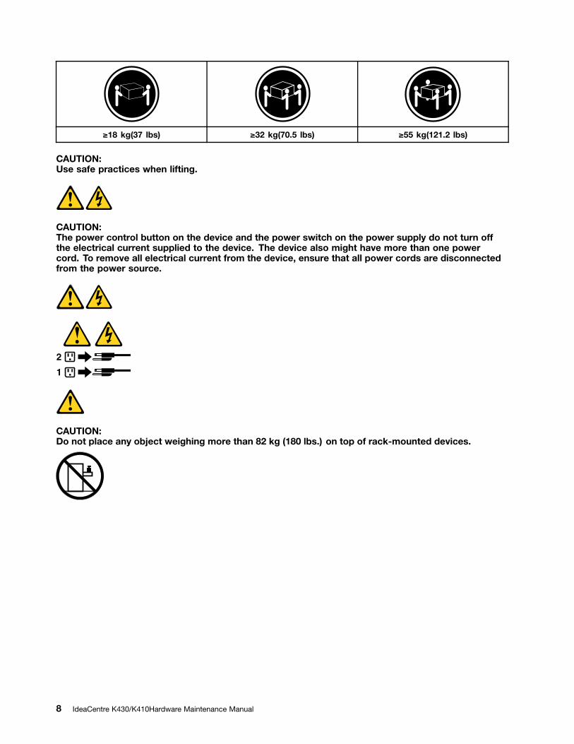
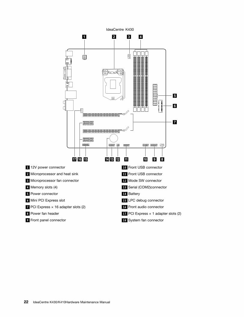
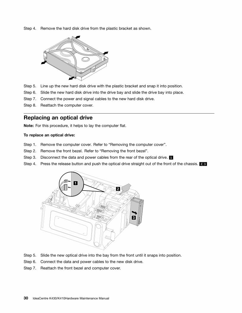

Step 1 Remove any media (disks CDs DVDs or memory cards) from the drives shut down the operatingsystem and turn off the computer and all attached devices
Step 2 Unplug all power cords from electrical outlets
Step 3 Disconnect all cables attached to the computer This includes power cords inputoutput (IO)cables and any other cables that are connected to the computer Refer to ldquoLeft and right viewrdquoand ldquoRear viewrdquo for help with locating the various connectors
Step 4 Remove the computer cover Refer to ldquoRemoving the computer coverrdquo
Step 5 Disconnect the fan power cable from the connector on the motherboard
Step 6 Remove the 4 screws that secure the microprocessor fan to the heat-sink and lift up themicroprocessor fan to remove it
Step 7 To install the new microprocessor fan
a Line up the new microprocessor fan with the heat-sink and secure it to the heat-sink with4 screws
b Connect the microprocessor fan power cable to the connector on the board
Step 8 Reattach the computer cover
Replacing the heat-sinkNote For this procedure it helps to lay the computer flat
To replace the heat-sink
Step 1 Remove any media (disks CDs DVDs or memory cards) from the drives shut down the operatingsystem and turn off the computer and all attached devices
Step 2 Unplug all power cords from electrical outlets
36 IdeaCentre K430K410Hardware Maintenance Manual
Step 3 Disconnect all cables attached to the computer This includes power cords inputoutput (IO)cables and any other cables that are connected to the computer Refer to ldquoLeft and right viewrdquoand ldquoRear viewrdquo for help with locating the various connectors
Step 4 Remove the computer cover Refer to ldquoRemoving the computer coverrdquo
Step 5 Remove the microprocessor fan Refer to ldquoReplacing the microprocessor fanrdquo
Step 6 Remove the 4 screws that secure the heat-sink to the motherboard
Step 7 Lift up the heat-sink to remove it
Step 8 Install the new heat-sinka Line up the screws on the new heat-sink with mounting holes on the motherboard and secure
it with the 4 screws
b Reattach the microprocessor fan to the heat-sink
c Reconnect the microprocessor fan power cable to the connector on the motherboard
Step 9 Reattach the computer cover
Replacing the CPUNote For this procedure it helps to lay the computer flat
To replace the CPU
Step 1 Remove any media (disks CDs DVDs or memory cards) from the drives shut down the operatingsystem and turn off the computer and all attached devices
Step 2 Unplug all power cords from electrical outlets
Step 3 Disconnect all cables attached to the computer This includes power cords inputoutput (IO)cables and any other cables that are connected to the computer Refer to ldquoLeft and right viewrdquoand ldquoRear viewrdquo for help with locating the various connectors
Chapter 8 Replacing hardware 37
Step 4 Remove the computer cover Refer to ldquoRemoving the computer coverrdquo
Step 5 Remove the microprocessor fan Refer to ldquoReplacing the microprocessor fanrdquo
Step 6 Remove the heat-sink Refer to ldquoReplacing the heat-sinkrdquo
Step 7 To remove the microprocessor 3 from the system board press then slide the small handle outto spring it up 1 and open the retainer 2
Attention Do not touch the gold contacts on the bottom of the microprocessor When handing themicroprocessor touch only the sides
Note Do not drop anything onto the microprocessor socket while it is exposed The socket pins mustbe kept as clean as possible
38 IdeaCentre K430K410Hardware Maintenance Manual
Step 8 Holding the sides of the microprocessor with your fingers remove the protective cover 1 thatprotects the gold contacts on the new microprocessor 2
Step 9 Holding the sides of the microprocessor with your fingers position the microprocessor so that thenotches on the microprocessor are aligned with the tabs in the microprocessor socket
Important To avoid damaging the microprocessor contacts keep the microprocessor completely levelwhile installing it into the socket
Step 10 Lower the microprocessor straight down into its socket on the motherboard
Step 11 To secure the microprocessor in the socket close the microprocessor retainer and lock it intoposition with the small handle
Step 12 Use a thermal grease syringe to place 5 drops of grease on the top of the microprocessor Eachdrop of grease should be 003ml (3 tick marks on the grease syringe)
Step 13 Reattach the heat-sink microprocessor fan computer cover
Replacing the Wi-Fi cardNote For this procedure it helps to lay the computer flat
Chapter 8 Replacing hardware 39
To replace the Wi-Fi card
Step 1 Remove any media (disks CDs DVDs or memory cards) from the drives shut down the operatingsystem and turn off the computer and all attached devices
Step 2 Unplug all power cords from electrical outlets
Step 3 Disconnect all cables attached to the computer This includes power cords inputoutput (IO)cables and any other cables that are connected to the computer Refer to ldquoLeft and right viewrdquoand ldquoRear viewrdquo for help with locating the various connectors
Step 4 Remove the computer cover Refer to ldquoRemoving the computer coverrdquo
Step 5 Disconnect the 2 antenna cables from the Wi-Fi card
Step 6 Remove the 2 screws that secure the Wi-Fi card to the motherboard
Step 7 Pull the Wi-Fi card upward to remove it from the card port
Step 8 Install the new Wi-Fi card
a Line up the new Wi-Fi card then insert it into the same card port
b Secure the Wi-Fi card to the motherboard with the 2 screws
c Connect the 2 antenna cables to the new Wi-Fi card
Step 9 Reattach the computer cover
Replacing the motherboardNote For this procedure it helps to lay the computer flat
To replace the motherboard
Step 1 Remove any media (disks CDs DVDs or memory cards) from the drives shut down the operatingsystem and turn off the computer and all attached devices
40 IdeaCentre K430K410Hardware Maintenance Manual
Step 2 Unplug all power cords from electrical outlets
Step 3 Disconnect all cables attached to the computer This includes power cords inputoutput (IO)cables and any other cables that are connected to the computer Refer to ldquoLeft and right viewrdquoand ldquoRear viewrdquo for help with locating the various connectors
Step 4 Remove the computer cover Refer to ldquoRemoving the computer coverrdquo
Step 5 Remove the memory module Refer to ldquoReplacing a memory modulerdquo
Step 6 Remove the microprocessor fan Refer to ldquoReplacing the microprocessor fanrdquo
Step 7 Remove the heat-sink Refer to ldquoReplacing the heat-sinkrdquo
Step 8 Remove the graphic card Refer to ldquoReplacing the graphic cardrdquo
Step 9 Remove the TV-Tuner card Refer to ldquoReplacing the TV-Tuner cardrdquo
Step 10 Remove the Wi-Fi card Refer to ldquoReplacing the Wi-Fi cardrdquo
Step 11 Remove the CPU Refer to ldquoReplacing the CPUrdquo
Step 12 Disconnect the all cables from the connectors on motherboard
Step 13 Remove the 8 screws that secure the motherboard to the chassis
Step 14 Slide then lift the motherboard out of the chassis to remove it
Step 15 Install the new motherboard
a Line up the holes on the new motherboard with mounting holes on the chassis and secureit with screws
b Reattach the memory module Wi-Fi card CPU and the heat-sink to the new motherboard
c Connect the all cables to the new motherboard
d Attach the graphic card and TV-Tuner card to the new motherboard
Step 16 Reattach the computer cover
FRU listsThis chapter lists the information on the field replaceable units (FRUs)
Attention Be sure to read and understand all the safety information before replacing any FRUs
Chapter 8 Replacing hardware 41
Notes FRUs that have a 1 or 2 in the CRU column are Customer Replaceable Units (CRUs)
bull 1ndash identifies parts that are fairly simple to replace requiring few or no tools
bull 2ndash identifies parts that are slightly more difficult to replace
bull N-identifies parts that are not to be replaced by the customer
Description Lenovo PN CRUID
Processor
I I73770K 35160081155 77 E1 CPU 1100334
I I73770 34160081155 77 E1 CPU 1100335
I I53570K 34160061155 77 E1 CPU 1100336
I I53550 33160061155 77 E1 CPU 1100337
I I53450 31160061155 77 E1 CPU 1100338
I I3-3220 33160031155 55 L1 CPUreg 1100456
I I3-3240 34160031155 55 L1 CPUreg 1100454
I I53330 30160061155 77 E1 CPU 1100393
I I52320 30133361155 95 D2 CPUreg 1100103
I SNB Ci3 2120 333M115565GT1 Q0reg 1007388
I I3 2130 34133331155 65 Q0 CPUreg 1100102
I G640 28310661155 65 Q0 CPU 1100474
N
Motherboard
ECS H61 MATX 10 95W MB RTL8111F_A662(R) 11200369
MSI Z75 MATX MB MP MBRTL8111E_ALC892reg 11200302
N
Heat Sink
TSL CEL3102836A6 Intel 6595W Cooler 31045550
AVC Z8UL06S012 Intel 6595W Cooler 31045549
N
Fan Module
FOX PV902512PSPF 0JG2 9225 Sysfan(R) 31039640
AVC DS09225R12HP183 9225 Sysfan(R) 31039310
AVC DS09225R12HP251 Frontfan 31500949
N
Memory
HMT325U6CFR8C-H9 2GB D3-1333 RAM-HF 1100200
MT8KTF25664AZ-1G4M1 2GB D3-1333 RAM-HF 1100201
Mic_R D9PFW 2GB DDRIII1333 RAM(R) 1100186
Mic_S D9PFW 2GB DDRIII1333 RAM(R) 1100187
Elp_R J2108BCSE-DJ-F 2GB DDRIII1333 RAMreg 1007495
Psc_S A3P2GF3CKF-GDJ 2GB D3-1333 RAM 1100044
M378B5773DH0-CH900 2GB DDRIII1333 RAMreg 1007407
Mic_S D9LGK 2GB DDRIII1333 RAM(R) 1006968
HMT325U6BFR8C-H9 2GB DDRIII1333 RAMreg 1006931
N
42 IdeaCentre K430K410Hardware Maintenance Manual
MT8JTF25664AZ-1G4D1 2GB DDRIII1333 RAM(R) 1007003
HMT351U6CFR8C-H9 4GB D3-1333 RAM-HF 1100203
MT16KTF51264AZ-1G4M1 4GB D3-1333 RAM-HF 1100204
EBJ41UF8BDW0-GN-F 4GB D3-1600 RAM-HF 1100216
Mic_R D9PFW 4GB DDRIII1333 RAM(R) 1100188
Mic_S D9PFW 4GB DDRIII1333 RAM(R) 1100189
Psc_S A3P2GF3CKF-GDJ 4GB D3-1333 RAM(R) 1100154
Elp_R J2108BCSE-DJ-F 4GB DDRIII1333 RAMreg 1100007
M378B5273DH0-CH900 4GB DDRIII1333 RAMreg 1007408
MT16JTF51264AZ-1G4D1 4GB DDRIII1333 RAM(R) 1006919
HMT351U6BFR8C-H9N0 4GB DDRIII1333 RAM(R) 1006920
HMT325U6CFR8C-H9 2GB D3-1333 RAM-HF 1-100200
HMT351U6CFR8C-H9 4GB D3-1333 RAM-HF 1-100203
MT8KTF25664AZ-1G4M1 2GB D3-1333 RAM-HF 1-100201
MT16KTF51264AZ-1G4M1 4GB D3-1333 RAM-HF 1-100204
Mic_S D9PFW 2GB DDRIII1333 RAM(R) 1-100187
Mic_S D9PFW 4GB DDRIII1333 RAM(R) 1-100189
Elp_R J2108BCSE-DJ-F 2GB DDRIII1333 RAMreg 1-007495
Elp_R J2108BCSE-DJ-F 4GB DDRIII1333 RAMreg 1-100007
M378B5773DH0-CH900 2GB DDRIII1333 RAMreg 1-007407
M378B5273DH0-CH900 4GB DDRIII1333 RAMreg 1-007408
M378B5773DH0-CK0 2GB D3-1600 RAM-HF 1-100209
HMT325U6CFR8C-PB 2GB D3-1600 RAM-HF 1-100210
MT8KTF25664AZ-1G6M1 2GB D3-1600 RAM-HF 1-100211
Elp_R J2108BDBG-GN-F 2GB D3-1600 RAM 1-100436
M378B5273DH0-CK0 4GB D3-1600 RAM-HF 1-100213
HMT351U6CFR8C-PB 4GB D3-1600 RAM-HF 1-100214
MT16KTF51264AZ-1G6M1 4GB D3-1600 RAM-HF 1-100215
Elp_R J2108BDBG-GN-F 4GB D3-1600 RAM 1-100437
M378B5773DH0CK0 2GB D31600RAMHF 1100209
HMT325U6CFR8CPB 2GB D31600RAMHF 1100210
MT8KTF25664AZ1G6M1 2GB D31600RAMHF 1100211
M378B5273DH0CK0 4GB D31600RAMHF 1100213
HMT351U6CFR8CPB 4GB D31600RAMHF 1100214
MT16KTF51264AZ1G6M1 4GB D31600RAMHF 1100215
M378B1G73BH0CK0 8GB D31600RAMHF 1100217
HMT41GU6MFR8CPB 8GB D31600RAMHF 1100218
MT16JTF1G64AZ1G6D1 8GB D31600RAMHF 1100096
Chapter 8 Replacing hardware 43
Hard Disk Drive
Seagate Pharaoh6Gbs ST3500413AS 500G HDDLH 16200064
WD XL500SM6G WD5000AAKX083CA1 500G HDDLH 16200031
Seagate Pharaoh 4K ST500DM002 500G HDDLH 16200178
Seagate Pharaoh6Gbs ST31000524AS 1TB HDDLH 16200065
WD XL500SM6G WD10EALX089BA1 1TB HDDLH 16200032
Seagate Grenada ST1000DM003 1TB HDDLH 16200182
Seagate Grenada ST1500DM003 15TB HDDLH 16200183
Hitachi HDS723020BLA642 2T64M7200SATA6G HDDLH 16005286
Seagate Grenada ST2000DM001 2TB HDDLH 16200184
Samsung PM830 64G mSATA SSD 16200109
Samsung PM830 128G mSATA SSD 16200110
2
Portable Hard Disk Drive
Lenovo Portable HardDrive(SP) F410(500G) 16005961
1
Optical Drive
PLDS 16XDH16ABSH SATA Black DVDRWLH 25011181
TSST 16XSH216AB SATA Black DVDRWLH 25200416
HLDS 16XGH70N SATA Black DVDRWLH 25200485
Optiarc16XAD7290H SATA Black DVDRWLH 25201497
PLDS 16XDH16ACSH SATA Black DVDRWLH 25201626
Panasoinc 16XSW810 SATA Black DVDRWLH 25201490
Optiarc16XAD7250H SATA Black DVDRWLH 25011199
HLDS BH30N Black BD RecorderLH(BE) 25200322
PLDS DH12B2SH HH Black BD RecorderLH 25202896
2
Graphic Card
Bitland HD7450512MADBH Graphic Card 11-200448
MSI HD7450512MADBH Graphic Card 11-200449
Bitland Geforce GT 6302GADBH Graphic Card 11-200899
Bitland Geforce GT 6201GADBH Graphic Card 11-200739
MSI Geforce 605512MADBH Graphic Card 11-200733
Bitland Geforce 605512MADBH Graphic Card 11-200737
MSI HD75702GADBH Graphic Card 11200576
Bitland HD74501GADBH Graphic Cardreg 11200452
MSI HD74501GADBH Graphic Cardreg 11200453
MSI HD77501GADDPH Graphic Card 11200901
MSI Geforce GT 5302GADBH Graphic Card 11200462
MSI Geforce 6051GADBH Graphic Card 11200731
Bitland Geforce GT 6201GADBH Graphic Card 11200739
MSI Geforce GTX 56025GA2DDPH Graphic Card 11200047
Bitland Geforce GT 54515GADBDH Graphic Card 11200046
2
44 IdeaCentre K430K410Hardware Maintenance Manual
Bitland Geforce GT 6302GADBH Graphic Card 11200899
Power Supply
HuntKey HK380-12GP S2(S7) ATX280W Power Supply 36-200158
LiteonPS-5281-7VR5-RoHS ATX280W Power Supply 36-200157
AcBelPC6001-EL9G ATX280W Power Supply 36-200156
FSP280-50EPA ATX280W 85 Power Supply 36-200161
LiteonPS-5281-02VA-RoHS ATX280W 85 Power Supply 36-200160
AcBelPC9008-EL1G ATX280W 85 Power Supply 36-200159
AcBel PC7033-EL0G 450W NEW CABLE Power Supply(R) 36-001873
AcBel PC6001EL6G ATX 280W Robust Power Supply(R) 36001720
HuntKey HK38012GP S2 ATX 280W WW Power Supply(R) 36001795
Liteon PS52817VR4ROHS ATX280W TW cap Power Supply 36002064
HuntKeyHK38012GP S2(S6) ATX280W Power Supplyreg 36002008
PS52817VR2RoHS 280W Robust Powerreg 36001721
AcBel PC6001EL8G ATX280W Power Supply 36200020
Liteon PS528102VA ATX 280W 85plus Power Supply(R) 36001697
AcBelPC9008EL0G ATX 280W 85plus Power Supply(R) 36001698
FSP28050EPA ATX 280W 85plusPower Supply(R) 36001699
Liteon PS53117VR3 110V220V 310W Power Supply(R) 36001874
HuntKeyHK41011FP 110V220V 310WPower Supplyreg 36002011
AcBel PC7033EL0G 450W NEW CABLE Power Supply(R) 36001873
AcBelFS8003EL1G 625W Power Supplyreg 36001663
ACBEL FS8003EL1G ES50 625W PSUreg 36200221
N
Wi-Fi Card
LTN RTL8188CE 11n HMC WiFi card 11200352
LS 400mm Antenna_Black_Roatan 31501133
LS 400mm Antenna_Gray_Roatan 31501134
N
TV-Tunner Card
YUAN PE988D DVBTampAnalog TV Tunner 11012024
YUAN PE988A ATSCampAnalog TV Tunner 11012025
JYT DMBTH 15Z TV Tunner 11012934
JYT SBTVDT 15Z TV Tunner 11012932
2
Remote Control
Phillips Win7 IR Black 43-key remote controller 888010934
Phillips Win7 IR receiver 888010662
SMK IR RC Win7 Japan 888011291
SMK IR Receiver Win7 Japan 888011292
1
Chapter 8 Replacing hardware 45
Cables
Luxshare460mm Thermal Cable 6PIN(R) 31034561
Grandsun 460mmThermal Cable 6PIN(R) 31045784
Grandsun 2H300mmSATA Cable with Latch(R) 31024767
Luxshare 2H300mmSATA Cable with Latch(R) 31024785
Grandsun 2H300mmSATA Cable with Latch(R) 31024767
Luxshare 2H300mmSATA Cable with Latch(R) 31024785
Grandsun 2H420mmSATA Cable with Latch(R) 31030139
Luxshare 2H420mmSATA Cable with Latch(R) 31024760
Grandsun 2H420mmSATA Cable with Latch(R) 31030139
Luxshare 2H420mmSATA Cable with Latch(R) 31024760
Grandsun 2H420mmSATA Cable with Latch(R) 31030139
Luxshare 2H420mmSATA Cable with Latch(R) 31024760
Luxshare 370mmSATA Cable 31034778
Grandsun 370mmSATA Cable 31034820
LS DVIDVI cable 18m 31501245
LX 200mmHDMI to DVIDS cablereg 31041295
Luxshare 130mm DVItoVGA cord(R) 31024556
JT VGA port cap 31049015
JT HDMI port cap 31049017
GS 2H100mm 4pinSATA cable Latchreg 31024761
Luxshare 2H100mm HDD Power Supply adaptor with Latch(R) 31024766
MSI graphics card SLI cable 31048424
ATI graphics card crossfire cable 31047520
JT Z75 MB rearIO shielding 31500766
N
Monitor
Lenovo Black LI2361dwATPVARWW 18200176
Lenovo Black LI2361dwATPVARCN 18200177
Lenovo L2262wATPVARWW 0560HB1 18004685
Lenovo Black L2262wATPVARCN 18004767
Lenovo L2262wTPVARWWW3YSD 18200125
Lenovo Black L2062wATPVARWW 18004891
Lenovo Black L2062wATPVARCN 18004890
Lenovo L2062wTPVARIDW3YSD 18200071
Lenovo L2364wATPVARWW 1187HB1 18200040
Lenovo L2364w ATPVARCN 18200041
Lenovo L2364w TPVARWWW3YSD 18200127
N
Speaker
Lenovo M0620 (black) 25013742
1
46 IdeaCentre K430K410Hardware Maintenance Manual
Mechanical
JT LX319 K4 chassis card bracket 31500767
JT mobile HDD case 31501000
RoatonK4 Bitland mSATA Conversion Card 11200762
JT SSD plastic bracket 31500999
JT M2X3 Dedicated Screw 31501076
N
Chassis
JT LX-319CTA Front Bezel 90200579
JT LX-319CTA Upper Bezel with Mode Switch amp Power Botton 90200580
JT LX-319CTA ODD holder 90200581
JT Tinian LX-320AT hard drive rail 31038607
AVC DS09225R12HP183 9225 Sysfan(R) 31039310
FOX PV902512PSPF 0J-G-2 9225 Sysfan(R) 31039640
AVC DS09225R12HP251 system fan 31500949
Foxconn 460 mm thermal sensor cable with 6 pins 31034567
Luxshare 6P 460mm sensor cable with holder 31034561
Luxshare K4 Ambient LED cable_400mm 31501040
JiaHao K4 Ambient LED cable_400mm 31501071
Bitland K4 Mode switch Card 11200417
Bitland RTS5182 front USB30 with card reader 11200656
Taisol GL839 Front USB30 with card reader 11200657
Bitland RTS5182 front USB30 with card reader 11200658
Taisol GL839 front USB30 with card reader 11200659
Luxshare K4 LEDswitch cable_650mm 31501041
JiaHao K4 LEDswitch cable_650mm 31501072
N
Keyboard amp Mouse
Sunrex LXH-EKB-10YA(TH) B-Silk KB-LVT 25200495
Sunrex LXH-EKB-10YA(CZ-SL) B-Silk KB-LVT 25200496
Sunrex LXH-EKB-10YA(IN) B-Silk KB-LVT 25200497
Sunrex LXH-EKB-10YA(US-EU) B-Silk KB-LVT 25200498
Sunrex LXH-EKB-10YA(RU) B-Silk KB-LVT 25200499
Sunrex LXH-EKB-10YA(UK) B-Silk KB-LVT 25200500
Sunrex LXH-EKB-10YA(Nordic) B-S KB-LVT 25200501
Sunrex LXH-EKB-10YA(LA) B-Silk KB-LVT 25200502
Sunrex LXH-EKB-10YA(AR) B-Silk KB-LVT 25200503
Sunrex LXH-EKB-10YA(SW) B-Silk KB-LVT 25200504
Sunrex LXH-EKB-10YA(GE) B-Silk KB-LVT 25200505
Sunrex LXH-EKB-10YA(TR) B-Silk KB-LVT 25200506
Sunrex LXH-EKB-10YA(IS) B-Silk KB-LVT 25200507
Sunrex LXH-EKB-10YA(PT) B-Silk KB-LVT 25200508
1
Chapter 8 Replacing hardware 47
Sunrex LXH-EKB-10YA(SP) B-Silk KB-LVT 25200509
Sunrex LXH-EKB-10YA(SL) B-Silk KB-LVT 25200510
Sunrex LXH-EKB-10YA(NL) B-Silk KB-LVT 25200511
Sunrex LXH-EKB-10YA(IT) B-Silk KB-LVT 25200512
Sunrex LXH-EKB-10YA(HB) B-Silk KB-LVT 25200513
Sunrex LXH-EKB-10YA(FR) B-Silk KB-LVT 25200514
Sunrex LXH-EKB-10YA(BE) B-Silk KB-LVT 25200515
Sunrex LXH-EKB-10YA(GK) B-Silk KB-LVT 25200516
Sunrex LXH-EKB-10YA(HG) B-Silk KB-LVT 25200517
Sunrex LXH-EKB-10YA(BG) B-Silk KB-LVT 25200518
Sunrex LXH-EKB-10YA(HR) B-Silk KB-LVT 25200519
Sunrex LXH-EKB-10YA(BR) B-Silk KB-LVT 25200520
Sunrex LXH-EKB-10YA(JP) B-Silk KB-LVT 25200521
Sunrex LXH-EKB-10YA(EN-FR) B-S KB-LVT 25201039
Liteon LXH-SM-8825 B-Silk Mouse 25200528
Chicony LXH-MSU-1111 B-Silk Mouse 25200529
Chicony LXH-MSU-1111 B-Silk Mouse 25203466
Sunrex LXH-EMS-10ZA B-Silk Mouse 25200530
Liteon SK-8861(US) S-Silk KB-Black(WW) 90200692
Liteon SK-8861(US-MY)S-Silk KB-Black(WW) 90200693
Liteon SK-8861(TW) S-Silk KB-Black(WW) 90200694
Liteon SK-8861(TH) S-Silk KB-Black(WW) 90200695
Liteon SK-8861(CS-SK)S-SilkKB-Black(WW) 90200696
Liteon SK-8861(US-IN)S-Silk KB-Black(WW) 90200697
Liteon SK-8861(US-EU)S-SilkKB-Black(WW) 90200698
Liteon SK-8861(RU) S-Silk KB-Black(WW) 90200699
Liteon SK-8861(GB) S-Silk KB-Black(WW) 90200700
Liteon SK-8861(Nordic)S-SilkKB-Black(WW) 90200701
Liteon SK-8861(LA) S-Silk KB-Black(WW) 90200702
Liteon SK-8861(LA-AR)S-Silk KB-Black(WW) 90200703
Liteon SK-8861(SA) S-Silk KB-Black(WW) 90200704
Liteon SK-8861(CH) S-Silk KB-Black(WW) 90200705
Liteon SK-8861(DE) S-Silk KB-Black(WW) 90200706
Liteon SK-8861(TR) S-Silk KB-Black(WW) 90200707
Liteon SK-8861(IS) S-Silk KB-Black(WW) 90200708
Liteon SK-8861(ES) S-Silk KB-Black(WW) 90200709
Liteon SK-8861(PT) S-Silk KB-Black(WW) 90200710
Liteon SK-8861(SL) S-Silk KB-Black(WW) 90200711
Liteon SK-8861(NL) S-Silk KB-Black(WW) 90200712
Liteon SK-8861(IT) S-Silk KB-Black(WW) 90200713
2
48 IdeaCentre K430K410Hardware Maintenance Manual
Liteon SK-8861(IL) S-Silk KB-Black(WW) 90200714
Liteon SK-8861(FR) S-Silk KB-Black(WW) 90200715
Liteon SK-8861(BE) S-Silk KB-Black(WW) 90200716
Liteon SK-8861(GR) S-Silk KB-Black(WW) 90200717
Liteon SK-8861(HU) S-Silk KB-Black(WW) 90200718
Liteon SK-8861(BG) S-Silk KB-Black(WW) 90200719
Liteon SK-8861(KR) S-Silk KB-Black(WW) 90200720
Liteon SK-8861(BR) S-Silk KB-Black(WW) 90200721
Liteon SK-8861(JP) S-Silk KB-Black(WW) 90200722
Liteon SK-8861(EN-FR)S-Silk KB-Black(WW) 90200723
Liteon SM-8861(WW) Mouse Black 90200724
Liteon SM-8861 Mouse(No Battery) Black 90200725
Liteon SM-8861(JP) Mouse-Black(WW) 90200779
Chapter 8 Replacing hardware 49
50 IdeaCentre K430K410Hardware Maintenance Manual
Chapter 9 General information
This chapter provides general information that applies to all machine types supported by this publication
Additional Service InformationThis chapter provides additional information that the service representative might find helpful
Power management
Power management reduces the power consumption of certain components of the computer such as thesystem power supply processor hard disk drives and some monitors
Advanced configuration and power interface (ACPI) BIOS
As this computer has an ACPI BIOS system the operating system is allowed to control the powermanagement features of the computer and the settings for Advanced Power Management (APM) BIOS modeis ignored Not all operating systems support ACPI BIOS mode
Automatic Power-On features
The Automatic Power-On features within the Power Management menu allow you to enable and disablefeatures that turn on the computer automatically
bull Wake Up on Alarm You can specify a date and time at which the computer will be turned on automaticallyThis can be either a single event a daily event or a weekly event
bull Wake Up on LAN This feature allows LAN adapter card to wake the System
copy Copyright Lenovo 2012 51

Step 3 Disconnect all cables attached to the computer This includes power cords inputoutput (IO)cables and any other cables that are connected to the computer Refer to ldquoLeft and right viewrdquoand ldquoRear viewrdquo for help with locating the various connectors
Step 4 Remove the computer cover Refer to ldquoRemoving the computer coverrdquo
Step 5 Remove the microprocessor fan Refer to ldquoReplacing the microprocessor fanrdquo
Step 6 Remove the 4 screws that secure the heat-sink to the motherboard
Step 7 Lift up the heat-sink to remove it
Step 8 Install the new heat-sinka Line up the screws on the new heat-sink with mounting holes on the motherboard and secure
it with the 4 screws
b Reattach the microprocessor fan to the heat-sink
c Reconnect the microprocessor fan power cable to the connector on the motherboard
Step 9 Reattach the computer cover
Replacing the CPUNote For this procedure it helps to lay the computer flat
To replace the CPU
Step 1 Remove any media (disks CDs DVDs or memory cards) from the drives shut down the operatingsystem and turn off the computer and all attached devices
Step 2 Unplug all power cords from electrical outlets
Step 3 Disconnect all cables attached to the computer This includes power cords inputoutput (IO)cables and any other cables that are connected to the computer Refer to ldquoLeft and right viewrdquoand ldquoRear viewrdquo for help with locating the various connectors
Chapter 8 Replacing hardware 37
Step 4 Remove the computer cover Refer to ldquoRemoving the computer coverrdquo
Step 5 Remove the microprocessor fan Refer to ldquoReplacing the microprocessor fanrdquo
Step 6 Remove the heat-sink Refer to ldquoReplacing the heat-sinkrdquo
Step 7 To remove the microprocessor 3 from the system board press then slide the small handle outto spring it up 1 and open the retainer 2
Attention Do not touch the gold contacts on the bottom of the microprocessor When handing themicroprocessor touch only the sides
Note Do not drop anything onto the microprocessor socket while it is exposed The socket pins mustbe kept as clean as possible
38 IdeaCentre K430K410Hardware Maintenance Manual
Step 8 Holding the sides of the microprocessor with your fingers remove the protective cover 1 thatprotects the gold contacts on the new microprocessor 2
Step 9 Holding the sides of the microprocessor with your fingers position the microprocessor so that thenotches on the microprocessor are aligned with the tabs in the microprocessor socket
Important To avoid damaging the microprocessor contacts keep the microprocessor completely levelwhile installing it into the socket
Step 10 Lower the microprocessor straight down into its socket on the motherboard
Step 11 To secure the microprocessor in the socket close the microprocessor retainer and lock it intoposition with the small handle
Step 12 Use a thermal grease syringe to place 5 drops of grease on the top of the microprocessor Eachdrop of grease should be 003ml (3 tick marks on the grease syringe)
Step 13 Reattach the heat-sink microprocessor fan computer cover
Replacing the Wi-Fi cardNote For this procedure it helps to lay the computer flat
Chapter 8 Replacing hardware 39
To replace the Wi-Fi card
Step 1 Remove any media (disks CDs DVDs or memory cards) from the drives shut down the operatingsystem and turn off the computer and all attached devices
Step 2 Unplug all power cords from electrical outlets
Step 3 Disconnect all cables attached to the computer This includes power cords inputoutput (IO)cables and any other cables that are connected to the computer Refer to ldquoLeft and right viewrdquoand ldquoRear viewrdquo for help with locating the various connectors
Step 4 Remove the computer cover Refer to ldquoRemoving the computer coverrdquo
Step 5 Disconnect the 2 antenna cables from the Wi-Fi card
Step 6 Remove the 2 screws that secure the Wi-Fi card to the motherboard
Step 7 Pull the Wi-Fi card upward to remove it from the card port
Step 8 Install the new Wi-Fi card
a Line up the new Wi-Fi card then insert it into the same card port
b Secure the Wi-Fi card to the motherboard with the 2 screws
c Connect the 2 antenna cables to the new Wi-Fi card
Step 9 Reattach the computer cover
Replacing the motherboardNote For this procedure it helps to lay the computer flat
To replace the motherboard
Step 1 Remove any media (disks CDs DVDs or memory cards) from the drives shut down the operatingsystem and turn off the computer and all attached devices
40 IdeaCentre K430K410Hardware Maintenance Manual
Step 2 Unplug all power cords from electrical outlets
Step 3 Disconnect all cables attached to the computer This includes power cords inputoutput (IO)cables and any other cables that are connected to the computer Refer to ldquoLeft and right viewrdquoand ldquoRear viewrdquo for help with locating the various connectors
Step 4 Remove the computer cover Refer to ldquoRemoving the computer coverrdquo
Step 5 Remove the memory module Refer to ldquoReplacing a memory modulerdquo
Step 6 Remove the microprocessor fan Refer to ldquoReplacing the microprocessor fanrdquo
Step 7 Remove the heat-sink Refer to ldquoReplacing the heat-sinkrdquo
Step 8 Remove the graphic card Refer to ldquoReplacing the graphic cardrdquo
Step 9 Remove the TV-Tuner card Refer to ldquoReplacing the TV-Tuner cardrdquo
Step 10 Remove the Wi-Fi card Refer to ldquoReplacing the Wi-Fi cardrdquo
Step 11 Remove the CPU Refer to ldquoReplacing the CPUrdquo
Step 12 Disconnect the all cables from the connectors on motherboard
Step 13 Remove the 8 screws that secure the motherboard to the chassis
Step 14 Slide then lift the motherboard out of the chassis to remove it
Step 15 Install the new motherboard
a Line up the holes on the new motherboard with mounting holes on the chassis and secureit with screws
b Reattach the memory module Wi-Fi card CPU and the heat-sink to the new motherboard
c Connect the all cables to the new motherboard
d Attach the graphic card and TV-Tuner card to the new motherboard
Step 16 Reattach the computer cover
FRU listsThis chapter lists the information on the field replaceable units (FRUs)
Attention Be sure to read and understand all the safety information before replacing any FRUs
Chapter 8 Replacing hardware 41
Notes FRUs that have a 1 or 2 in the CRU column are Customer Replaceable Units (CRUs)
bull 1ndash identifies parts that are fairly simple to replace requiring few or no tools
bull 2ndash identifies parts that are slightly more difficult to replace
bull N-identifies parts that are not to be replaced by the customer
Description Lenovo PN CRUID
Processor
I I73770K 35160081155 77 E1 CPU 1100334
I I73770 34160081155 77 E1 CPU 1100335
I I53570K 34160061155 77 E1 CPU 1100336
I I53550 33160061155 77 E1 CPU 1100337
I I53450 31160061155 77 E1 CPU 1100338
I I3-3220 33160031155 55 L1 CPUreg 1100456
I I3-3240 34160031155 55 L1 CPUreg 1100454
I I53330 30160061155 77 E1 CPU 1100393
I I52320 30133361155 95 D2 CPUreg 1100103
I SNB Ci3 2120 333M115565GT1 Q0reg 1007388
I I3 2130 34133331155 65 Q0 CPUreg 1100102
I G640 28310661155 65 Q0 CPU 1100474
N
Motherboard
ECS H61 MATX 10 95W MB RTL8111F_A662(R) 11200369
MSI Z75 MATX MB MP MBRTL8111E_ALC892reg 11200302
N
Heat Sink
TSL CEL3102836A6 Intel 6595W Cooler 31045550
AVC Z8UL06S012 Intel 6595W Cooler 31045549
N
Fan Module
FOX PV902512PSPF 0JG2 9225 Sysfan(R) 31039640
AVC DS09225R12HP183 9225 Sysfan(R) 31039310
AVC DS09225R12HP251 Frontfan 31500949
N
Memory
HMT325U6CFR8C-H9 2GB D3-1333 RAM-HF 1100200
MT8KTF25664AZ-1G4M1 2GB D3-1333 RAM-HF 1100201
Mic_R D9PFW 2GB DDRIII1333 RAM(R) 1100186
Mic_S D9PFW 2GB DDRIII1333 RAM(R) 1100187
Elp_R J2108BCSE-DJ-F 2GB DDRIII1333 RAMreg 1007495
Psc_S A3P2GF3CKF-GDJ 2GB D3-1333 RAM 1100044
M378B5773DH0-CH900 2GB DDRIII1333 RAMreg 1007407
Mic_S D9LGK 2GB DDRIII1333 RAM(R) 1006968
HMT325U6BFR8C-H9 2GB DDRIII1333 RAMreg 1006931
N
42 IdeaCentre K430K410Hardware Maintenance Manual
MT8JTF25664AZ-1G4D1 2GB DDRIII1333 RAM(R) 1007003
HMT351U6CFR8C-H9 4GB D3-1333 RAM-HF 1100203
MT16KTF51264AZ-1G4M1 4GB D3-1333 RAM-HF 1100204
EBJ41UF8BDW0-GN-F 4GB D3-1600 RAM-HF 1100216
Mic_R D9PFW 4GB DDRIII1333 RAM(R) 1100188
Mic_S D9PFW 4GB DDRIII1333 RAM(R) 1100189
Psc_S A3P2GF3CKF-GDJ 4GB D3-1333 RAM(R) 1100154
Elp_R J2108BCSE-DJ-F 4GB DDRIII1333 RAMreg 1100007
M378B5273DH0-CH900 4GB DDRIII1333 RAMreg 1007408
MT16JTF51264AZ-1G4D1 4GB DDRIII1333 RAM(R) 1006919
HMT351U6BFR8C-H9N0 4GB DDRIII1333 RAM(R) 1006920
HMT325U6CFR8C-H9 2GB D3-1333 RAM-HF 1-100200
HMT351U6CFR8C-H9 4GB D3-1333 RAM-HF 1-100203
MT8KTF25664AZ-1G4M1 2GB D3-1333 RAM-HF 1-100201
MT16KTF51264AZ-1G4M1 4GB D3-1333 RAM-HF 1-100204
Mic_S D9PFW 2GB DDRIII1333 RAM(R) 1-100187
Mic_S D9PFW 4GB DDRIII1333 RAM(R) 1-100189
Elp_R J2108BCSE-DJ-F 2GB DDRIII1333 RAMreg 1-007495
Elp_R J2108BCSE-DJ-F 4GB DDRIII1333 RAMreg 1-100007
M378B5773DH0-CH900 2GB DDRIII1333 RAMreg 1-007407
M378B5273DH0-CH900 4GB DDRIII1333 RAMreg 1-007408
M378B5773DH0-CK0 2GB D3-1600 RAM-HF 1-100209
HMT325U6CFR8C-PB 2GB D3-1600 RAM-HF 1-100210
MT8KTF25664AZ-1G6M1 2GB D3-1600 RAM-HF 1-100211
Elp_R J2108BDBG-GN-F 2GB D3-1600 RAM 1-100436
M378B5273DH0-CK0 4GB D3-1600 RAM-HF 1-100213
HMT351U6CFR8C-PB 4GB D3-1600 RAM-HF 1-100214
MT16KTF51264AZ-1G6M1 4GB D3-1600 RAM-HF 1-100215
Elp_R J2108BDBG-GN-F 4GB D3-1600 RAM 1-100437
M378B5773DH0CK0 2GB D31600RAMHF 1100209
HMT325U6CFR8CPB 2GB D31600RAMHF 1100210
MT8KTF25664AZ1G6M1 2GB D31600RAMHF 1100211
M378B5273DH0CK0 4GB D31600RAMHF 1100213
HMT351U6CFR8CPB 4GB D31600RAMHF 1100214
MT16KTF51264AZ1G6M1 4GB D31600RAMHF 1100215
M378B1G73BH0CK0 8GB D31600RAMHF 1100217
HMT41GU6MFR8CPB 8GB D31600RAMHF 1100218
MT16JTF1G64AZ1G6D1 8GB D31600RAMHF 1100096
Chapter 8 Replacing hardware 43
Hard Disk Drive
Seagate Pharaoh6Gbs ST3500413AS 500G HDDLH 16200064
WD XL500SM6G WD5000AAKX083CA1 500G HDDLH 16200031
Seagate Pharaoh 4K ST500DM002 500G HDDLH 16200178
Seagate Pharaoh6Gbs ST31000524AS 1TB HDDLH 16200065
WD XL500SM6G WD10EALX089BA1 1TB HDDLH 16200032
Seagate Grenada ST1000DM003 1TB HDDLH 16200182
Seagate Grenada ST1500DM003 15TB HDDLH 16200183
Hitachi HDS723020BLA642 2T64M7200SATA6G HDDLH 16005286
Seagate Grenada ST2000DM001 2TB HDDLH 16200184
Samsung PM830 64G mSATA SSD 16200109
Samsung PM830 128G mSATA SSD 16200110
2
Portable Hard Disk Drive
Lenovo Portable HardDrive(SP) F410(500G) 16005961
1
Optical Drive
PLDS 16XDH16ABSH SATA Black DVDRWLH 25011181
TSST 16XSH216AB SATA Black DVDRWLH 25200416
HLDS 16XGH70N SATA Black DVDRWLH 25200485
Optiarc16XAD7290H SATA Black DVDRWLH 25201497
PLDS 16XDH16ACSH SATA Black DVDRWLH 25201626
Panasoinc 16XSW810 SATA Black DVDRWLH 25201490
Optiarc16XAD7250H SATA Black DVDRWLH 25011199
HLDS BH30N Black BD RecorderLH(BE) 25200322
PLDS DH12B2SH HH Black BD RecorderLH 25202896
2
Graphic Card
Bitland HD7450512MADBH Graphic Card 11-200448
MSI HD7450512MADBH Graphic Card 11-200449
Bitland Geforce GT 6302GADBH Graphic Card 11-200899
Bitland Geforce GT 6201GADBH Graphic Card 11-200739
MSI Geforce 605512MADBH Graphic Card 11-200733
Bitland Geforce 605512MADBH Graphic Card 11-200737
MSI HD75702GADBH Graphic Card 11200576
Bitland HD74501GADBH Graphic Cardreg 11200452
MSI HD74501GADBH Graphic Cardreg 11200453
MSI HD77501GADDPH Graphic Card 11200901
MSI Geforce GT 5302GADBH Graphic Card 11200462
MSI Geforce 6051GADBH Graphic Card 11200731
Bitland Geforce GT 6201GADBH Graphic Card 11200739
MSI Geforce GTX 56025GA2DDPH Graphic Card 11200047
Bitland Geforce GT 54515GADBDH Graphic Card 11200046
2
44 IdeaCentre K430K410Hardware Maintenance Manual
Bitland Geforce GT 6302GADBH Graphic Card 11200899
Power Supply
HuntKey HK380-12GP S2(S7) ATX280W Power Supply 36-200158
LiteonPS-5281-7VR5-RoHS ATX280W Power Supply 36-200157
AcBelPC6001-EL9G ATX280W Power Supply 36-200156
FSP280-50EPA ATX280W 85 Power Supply 36-200161
LiteonPS-5281-02VA-RoHS ATX280W 85 Power Supply 36-200160
AcBelPC9008-EL1G ATX280W 85 Power Supply 36-200159
AcBel PC7033-EL0G 450W NEW CABLE Power Supply(R) 36-001873
AcBel PC6001EL6G ATX 280W Robust Power Supply(R) 36001720
HuntKey HK38012GP S2 ATX 280W WW Power Supply(R) 36001795
Liteon PS52817VR4ROHS ATX280W TW cap Power Supply 36002064
HuntKeyHK38012GP S2(S6) ATX280W Power Supplyreg 36002008
PS52817VR2RoHS 280W Robust Powerreg 36001721
AcBel PC6001EL8G ATX280W Power Supply 36200020
Liteon PS528102VA ATX 280W 85plus Power Supply(R) 36001697
AcBelPC9008EL0G ATX 280W 85plus Power Supply(R) 36001698
FSP28050EPA ATX 280W 85plusPower Supply(R) 36001699
Liteon PS53117VR3 110V220V 310W Power Supply(R) 36001874
HuntKeyHK41011FP 110V220V 310WPower Supplyreg 36002011
AcBel PC7033EL0G 450W NEW CABLE Power Supply(R) 36001873
AcBelFS8003EL1G 625W Power Supplyreg 36001663
ACBEL FS8003EL1G ES50 625W PSUreg 36200221
N
Wi-Fi Card
LTN RTL8188CE 11n HMC WiFi card 11200352
LS 400mm Antenna_Black_Roatan 31501133
LS 400mm Antenna_Gray_Roatan 31501134
N
TV-Tunner Card
YUAN PE988D DVBTampAnalog TV Tunner 11012024
YUAN PE988A ATSCampAnalog TV Tunner 11012025
JYT DMBTH 15Z TV Tunner 11012934
JYT SBTVDT 15Z TV Tunner 11012932
2
Remote Control
Phillips Win7 IR Black 43-key remote controller 888010934
Phillips Win7 IR receiver 888010662
SMK IR RC Win7 Japan 888011291
SMK IR Receiver Win7 Japan 888011292
1
Chapter 8 Replacing hardware 45
Cables
Luxshare460mm Thermal Cable 6PIN(R) 31034561
Grandsun 460mmThermal Cable 6PIN(R) 31045784
Grandsun 2H300mmSATA Cable with Latch(R) 31024767
Luxshare 2H300mmSATA Cable with Latch(R) 31024785
Grandsun 2H300mmSATA Cable with Latch(R) 31024767
Luxshare 2H300mmSATA Cable with Latch(R) 31024785
Grandsun 2H420mmSATA Cable with Latch(R) 31030139
Luxshare 2H420mmSATA Cable with Latch(R) 31024760
Grandsun 2H420mmSATA Cable with Latch(R) 31030139
Luxshare 2H420mmSATA Cable with Latch(R) 31024760
Grandsun 2H420mmSATA Cable with Latch(R) 31030139
Luxshare 2H420mmSATA Cable with Latch(R) 31024760
Luxshare 370mmSATA Cable 31034778
Grandsun 370mmSATA Cable 31034820
LS DVIDVI cable 18m 31501245
LX 200mmHDMI to DVIDS cablereg 31041295
Luxshare 130mm DVItoVGA cord(R) 31024556
JT VGA port cap 31049015
JT HDMI port cap 31049017
GS 2H100mm 4pinSATA cable Latchreg 31024761
Luxshare 2H100mm HDD Power Supply adaptor with Latch(R) 31024766
MSI graphics card SLI cable 31048424
ATI graphics card crossfire cable 31047520
JT Z75 MB rearIO shielding 31500766
N
Monitor
Lenovo Black LI2361dwATPVARWW 18200176
Lenovo Black LI2361dwATPVARCN 18200177
Lenovo L2262wATPVARWW 0560HB1 18004685
Lenovo Black L2262wATPVARCN 18004767
Lenovo L2262wTPVARWWW3YSD 18200125
Lenovo Black L2062wATPVARWW 18004891
Lenovo Black L2062wATPVARCN 18004890
Lenovo L2062wTPVARIDW3YSD 18200071
Lenovo L2364wATPVARWW 1187HB1 18200040
Lenovo L2364w ATPVARCN 18200041
Lenovo L2364w TPVARWWW3YSD 18200127
N
Speaker
Lenovo M0620 (black) 25013742
1
46 IdeaCentre K430K410Hardware Maintenance Manual
Mechanical
JT LX319 K4 chassis card bracket 31500767
JT mobile HDD case 31501000
RoatonK4 Bitland mSATA Conversion Card 11200762
JT SSD plastic bracket 31500999
JT M2X3 Dedicated Screw 31501076
N
Chassis
JT LX-319CTA Front Bezel 90200579
JT LX-319CTA Upper Bezel with Mode Switch amp Power Botton 90200580
JT LX-319CTA ODD holder 90200581
JT Tinian LX-320AT hard drive rail 31038607
AVC DS09225R12HP183 9225 Sysfan(R) 31039310
FOX PV902512PSPF 0J-G-2 9225 Sysfan(R) 31039640
AVC DS09225R12HP251 system fan 31500949
Foxconn 460 mm thermal sensor cable with 6 pins 31034567
Luxshare 6P 460mm sensor cable with holder 31034561
Luxshare K4 Ambient LED cable_400mm 31501040
JiaHao K4 Ambient LED cable_400mm 31501071
Bitland K4 Mode switch Card 11200417
Bitland RTS5182 front USB30 with card reader 11200656
Taisol GL839 Front USB30 with card reader 11200657
Bitland RTS5182 front USB30 with card reader 11200658
Taisol GL839 front USB30 with card reader 11200659
Luxshare K4 LEDswitch cable_650mm 31501041
JiaHao K4 LEDswitch cable_650mm 31501072
N
Keyboard amp Mouse
Sunrex LXH-EKB-10YA(TH) B-Silk KB-LVT 25200495
Sunrex LXH-EKB-10YA(CZ-SL) B-Silk KB-LVT 25200496
Sunrex LXH-EKB-10YA(IN) B-Silk KB-LVT 25200497
Sunrex LXH-EKB-10YA(US-EU) B-Silk KB-LVT 25200498
Sunrex LXH-EKB-10YA(RU) B-Silk KB-LVT 25200499
Sunrex LXH-EKB-10YA(UK) B-Silk KB-LVT 25200500
Sunrex LXH-EKB-10YA(Nordic) B-S KB-LVT 25200501
Sunrex LXH-EKB-10YA(LA) B-Silk KB-LVT 25200502
Sunrex LXH-EKB-10YA(AR) B-Silk KB-LVT 25200503
Sunrex LXH-EKB-10YA(SW) B-Silk KB-LVT 25200504
Sunrex LXH-EKB-10YA(GE) B-Silk KB-LVT 25200505
Sunrex LXH-EKB-10YA(TR) B-Silk KB-LVT 25200506
Sunrex LXH-EKB-10YA(IS) B-Silk KB-LVT 25200507
Sunrex LXH-EKB-10YA(PT) B-Silk KB-LVT 25200508
1
Chapter 8 Replacing hardware 47
Sunrex LXH-EKB-10YA(SP) B-Silk KB-LVT 25200509
Sunrex LXH-EKB-10YA(SL) B-Silk KB-LVT 25200510
Sunrex LXH-EKB-10YA(NL) B-Silk KB-LVT 25200511
Sunrex LXH-EKB-10YA(IT) B-Silk KB-LVT 25200512
Sunrex LXH-EKB-10YA(HB) B-Silk KB-LVT 25200513
Sunrex LXH-EKB-10YA(FR) B-Silk KB-LVT 25200514
Sunrex LXH-EKB-10YA(BE) B-Silk KB-LVT 25200515
Sunrex LXH-EKB-10YA(GK) B-Silk KB-LVT 25200516
Sunrex LXH-EKB-10YA(HG) B-Silk KB-LVT 25200517
Sunrex LXH-EKB-10YA(BG) B-Silk KB-LVT 25200518
Sunrex LXH-EKB-10YA(HR) B-Silk KB-LVT 25200519
Sunrex LXH-EKB-10YA(BR) B-Silk KB-LVT 25200520
Sunrex LXH-EKB-10YA(JP) B-Silk KB-LVT 25200521
Sunrex LXH-EKB-10YA(EN-FR) B-S KB-LVT 25201039
Liteon LXH-SM-8825 B-Silk Mouse 25200528
Chicony LXH-MSU-1111 B-Silk Mouse 25200529
Chicony LXH-MSU-1111 B-Silk Mouse 25203466
Sunrex LXH-EMS-10ZA B-Silk Mouse 25200530
Liteon SK-8861(US) S-Silk KB-Black(WW) 90200692
Liteon SK-8861(US-MY)S-Silk KB-Black(WW) 90200693
Liteon SK-8861(TW) S-Silk KB-Black(WW) 90200694
Liteon SK-8861(TH) S-Silk KB-Black(WW) 90200695
Liteon SK-8861(CS-SK)S-SilkKB-Black(WW) 90200696
Liteon SK-8861(US-IN)S-Silk KB-Black(WW) 90200697
Liteon SK-8861(US-EU)S-SilkKB-Black(WW) 90200698
Liteon SK-8861(RU) S-Silk KB-Black(WW) 90200699
Liteon SK-8861(GB) S-Silk KB-Black(WW) 90200700
Liteon SK-8861(Nordic)S-SilkKB-Black(WW) 90200701
Liteon SK-8861(LA) S-Silk KB-Black(WW) 90200702
Liteon SK-8861(LA-AR)S-Silk KB-Black(WW) 90200703
Liteon SK-8861(SA) S-Silk KB-Black(WW) 90200704
Liteon SK-8861(CH) S-Silk KB-Black(WW) 90200705
Liteon SK-8861(DE) S-Silk KB-Black(WW) 90200706
Liteon SK-8861(TR) S-Silk KB-Black(WW) 90200707
Liteon SK-8861(IS) S-Silk KB-Black(WW) 90200708
Liteon SK-8861(ES) S-Silk KB-Black(WW) 90200709
Liteon SK-8861(PT) S-Silk KB-Black(WW) 90200710
Liteon SK-8861(SL) S-Silk KB-Black(WW) 90200711
Liteon SK-8861(NL) S-Silk KB-Black(WW) 90200712
Liteon SK-8861(IT) S-Silk KB-Black(WW) 90200713
2
48 IdeaCentre K430K410Hardware Maintenance Manual
Liteon SK-8861(IL) S-Silk KB-Black(WW) 90200714
Liteon SK-8861(FR) S-Silk KB-Black(WW) 90200715
Liteon SK-8861(BE) S-Silk KB-Black(WW) 90200716
Liteon SK-8861(GR) S-Silk KB-Black(WW) 90200717
Liteon SK-8861(HU) S-Silk KB-Black(WW) 90200718
Liteon SK-8861(BG) S-Silk KB-Black(WW) 90200719
Liteon SK-8861(KR) S-Silk KB-Black(WW) 90200720
Liteon SK-8861(BR) S-Silk KB-Black(WW) 90200721
Liteon SK-8861(JP) S-Silk KB-Black(WW) 90200722
Liteon SK-8861(EN-FR)S-Silk KB-Black(WW) 90200723
Liteon SM-8861(WW) Mouse Black 90200724
Liteon SM-8861 Mouse(No Battery) Black 90200725
Liteon SM-8861(JP) Mouse-Black(WW) 90200779
Chapter 8 Replacing hardware 49
50 IdeaCentre K430K410Hardware Maintenance Manual
Chapter 9 General information
This chapter provides general information that applies to all machine types supported by this publication
Additional Service InformationThis chapter provides additional information that the service representative might find helpful
Power management
Power management reduces the power consumption of certain components of the computer such as thesystem power supply processor hard disk drives and some monitors
Advanced configuration and power interface (ACPI) BIOS
As this computer has an ACPI BIOS system the operating system is allowed to control the powermanagement features of the computer and the settings for Advanced Power Management (APM) BIOS modeis ignored Not all operating systems support ACPI BIOS mode
Automatic Power-On features
The Automatic Power-On features within the Power Management menu allow you to enable and disablefeatures that turn on the computer automatically
bull Wake Up on Alarm You can specify a date and time at which the computer will be turned on automaticallyThis can be either a single event a daily event or a weekly event
bull Wake Up on LAN This feature allows LAN adapter card to wake the System
copy Copyright Lenovo 2012 51

Step 4 Remove the computer cover Refer to ldquoRemoving the computer coverrdquo
Step 5 Remove the microprocessor fan Refer to ldquoReplacing the microprocessor fanrdquo
Step 6 Remove the heat-sink Refer to ldquoReplacing the heat-sinkrdquo
Step 7 To remove the microprocessor 3 from the system board press then slide the small handle outto spring it up 1 and open the retainer 2
Attention Do not touch the gold contacts on the bottom of the microprocessor When handing themicroprocessor touch only the sides
Note Do not drop anything onto the microprocessor socket while it is exposed The socket pins mustbe kept as clean as possible
38 IdeaCentre K430K410Hardware Maintenance Manual
Step 8 Holding the sides of the microprocessor with your fingers remove the protective cover 1 thatprotects the gold contacts on the new microprocessor 2
Step 9 Holding the sides of the microprocessor with your fingers position the microprocessor so that thenotches on the microprocessor are aligned with the tabs in the microprocessor socket
Important To avoid damaging the microprocessor contacts keep the microprocessor completely levelwhile installing it into the socket
Step 10 Lower the microprocessor straight down into its socket on the motherboard
Step 11 To secure the microprocessor in the socket close the microprocessor retainer and lock it intoposition with the small handle
Step 12 Use a thermal grease syringe to place 5 drops of grease on the top of the microprocessor Eachdrop of grease should be 003ml (3 tick marks on the grease syringe)
Step 13 Reattach the heat-sink microprocessor fan computer cover
Replacing the Wi-Fi cardNote For this procedure it helps to lay the computer flat
Chapter 8 Replacing hardware 39
To replace the Wi-Fi card
Step 1 Remove any media (disks CDs DVDs or memory cards) from the drives shut down the operatingsystem and turn off the computer and all attached devices
Step 2 Unplug all power cords from electrical outlets
Step 3 Disconnect all cables attached to the computer This includes power cords inputoutput (IO)cables and any other cables that are connected to the computer Refer to ldquoLeft and right viewrdquoand ldquoRear viewrdquo for help with locating the various connectors
Step 4 Remove the computer cover Refer to ldquoRemoving the computer coverrdquo
Step 5 Disconnect the 2 antenna cables from the Wi-Fi card
Step 6 Remove the 2 screws that secure the Wi-Fi card to the motherboard
Step 7 Pull the Wi-Fi card upward to remove it from the card port
Step 8 Install the new Wi-Fi card
a Line up the new Wi-Fi card then insert it into the same card port
b Secure the Wi-Fi card to the motherboard with the 2 screws
c Connect the 2 antenna cables to the new Wi-Fi card
Step 9 Reattach the computer cover
Replacing the motherboardNote For this procedure it helps to lay the computer flat
To replace the motherboard
Step 1 Remove any media (disks CDs DVDs or memory cards) from the drives shut down the operatingsystem and turn off the computer and all attached devices
40 IdeaCentre K430K410Hardware Maintenance Manual
Step 2 Unplug all power cords from electrical outlets
Step 3 Disconnect all cables attached to the computer This includes power cords inputoutput (IO)cables and any other cables that are connected to the computer Refer to ldquoLeft and right viewrdquoand ldquoRear viewrdquo for help with locating the various connectors
Step 4 Remove the computer cover Refer to ldquoRemoving the computer coverrdquo
Step 5 Remove the memory module Refer to ldquoReplacing a memory modulerdquo
Step 6 Remove the microprocessor fan Refer to ldquoReplacing the microprocessor fanrdquo
Step 7 Remove the heat-sink Refer to ldquoReplacing the heat-sinkrdquo
Step 8 Remove the graphic card Refer to ldquoReplacing the graphic cardrdquo
Step 9 Remove the TV-Tuner card Refer to ldquoReplacing the TV-Tuner cardrdquo
Step 10 Remove the Wi-Fi card Refer to ldquoReplacing the Wi-Fi cardrdquo
Step 11 Remove the CPU Refer to ldquoReplacing the CPUrdquo
Step 12 Disconnect the all cables from the connectors on motherboard
Step 13 Remove the 8 screws that secure the motherboard to the chassis
Step 14 Slide then lift the motherboard out of the chassis to remove it
Step 15 Install the new motherboard
a Line up the holes on the new motherboard with mounting holes on the chassis and secureit with screws
b Reattach the memory module Wi-Fi card CPU and the heat-sink to the new motherboard
c Connect the all cables to the new motherboard
d Attach the graphic card and TV-Tuner card to the new motherboard
Step 16 Reattach the computer cover
FRU listsThis chapter lists the information on the field replaceable units (FRUs)
Attention Be sure to read and understand all the safety information before replacing any FRUs
Chapter 8 Replacing hardware 41
Notes FRUs that have a 1 or 2 in the CRU column are Customer Replaceable Units (CRUs)
bull 1ndash identifies parts that are fairly simple to replace requiring few or no tools
bull 2ndash identifies parts that are slightly more difficult to replace
bull N-identifies parts that are not to be replaced by the customer
Description Lenovo PN CRUID
Processor
I I73770K 35160081155 77 E1 CPU 1100334
I I73770 34160081155 77 E1 CPU 1100335
I I53570K 34160061155 77 E1 CPU 1100336
I I53550 33160061155 77 E1 CPU 1100337
I I53450 31160061155 77 E1 CPU 1100338
I I3-3220 33160031155 55 L1 CPUreg 1100456
I I3-3240 34160031155 55 L1 CPUreg 1100454
I I53330 30160061155 77 E1 CPU 1100393
I I52320 30133361155 95 D2 CPUreg 1100103
I SNB Ci3 2120 333M115565GT1 Q0reg 1007388
I I3 2130 34133331155 65 Q0 CPUreg 1100102
I G640 28310661155 65 Q0 CPU 1100474
N
Motherboard
ECS H61 MATX 10 95W MB RTL8111F_A662(R) 11200369
MSI Z75 MATX MB MP MBRTL8111E_ALC892reg 11200302
N
Heat Sink
TSL CEL3102836A6 Intel 6595W Cooler 31045550
AVC Z8UL06S012 Intel 6595W Cooler 31045549
N
Fan Module
FOX PV902512PSPF 0JG2 9225 Sysfan(R) 31039640
AVC DS09225R12HP183 9225 Sysfan(R) 31039310
AVC DS09225R12HP251 Frontfan 31500949
N
Memory
HMT325U6CFR8C-H9 2GB D3-1333 RAM-HF 1100200
MT8KTF25664AZ-1G4M1 2GB D3-1333 RAM-HF 1100201
Mic_R D9PFW 2GB DDRIII1333 RAM(R) 1100186
Mic_S D9PFW 2GB DDRIII1333 RAM(R) 1100187
Elp_R J2108BCSE-DJ-F 2GB DDRIII1333 RAMreg 1007495
Psc_S A3P2GF3CKF-GDJ 2GB D3-1333 RAM 1100044
M378B5773DH0-CH900 2GB DDRIII1333 RAMreg 1007407
Mic_S D9LGK 2GB DDRIII1333 RAM(R) 1006968
HMT325U6BFR8C-H9 2GB DDRIII1333 RAMreg 1006931
N
42 IdeaCentre K430K410Hardware Maintenance Manual
MT8JTF25664AZ-1G4D1 2GB DDRIII1333 RAM(R) 1007003
HMT351U6CFR8C-H9 4GB D3-1333 RAM-HF 1100203
MT16KTF51264AZ-1G4M1 4GB D3-1333 RAM-HF 1100204
EBJ41UF8BDW0-GN-F 4GB D3-1600 RAM-HF 1100216
Mic_R D9PFW 4GB DDRIII1333 RAM(R) 1100188
Mic_S D9PFW 4GB DDRIII1333 RAM(R) 1100189
Psc_S A3P2GF3CKF-GDJ 4GB D3-1333 RAM(R) 1100154
Elp_R J2108BCSE-DJ-F 4GB DDRIII1333 RAMreg 1100007
M378B5273DH0-CH900 4GB DDRIII1333 RAMreg 1007408
MT16JTF51264AZ-1G4D1 4GB DDRIII1333 RAM(R) 1006919
HMT351U6BFR8C-H9N0 4GB DDRIII1333 RAM(R) 1006920
HMT325U6CFR8C-H9 2GB D3-1333 RAM-HF 1-100200
HMT351U6CFR8C-H9 4GB D3-1333 RAM-HF 1-100203
MT8KTF25664AZ-1G4M1 2GB D3-1333 RAM-HF 1-100201
MT16KTF51264AZ-1G4M1 4GB D3-1333 RAM-HF 1-100204
Mic_S D9PFW 2GB DDRIII1333 RAM(R) 1-100187
Mic_S D9PFW 4GB DDRIII1333 RAM(R) 1-100189
Elp_R J2108BCSE-DJ-F 2GB DDRIII1333 RAMreg 1-007495
Elp_R J2108BCSE-DJ-F 4GB DDRIII1333 RAMreg 1-100007
M378B5773DH0-CH900 2GB DDRIII1333 RAMreg 1-007407
M378B5273DH0-CH900 4GB DDRIII1333 RAMreg 1-007408
M378B5773DH0-CK0 2GB D3-1600 RAM-HF 1-100209
HMT325U6CFR8C-PB 2GB D3-1600 RAM-HF 1-100210
MT8KTF25664AZ-1G6M1 2GB D3-1600 RAM-HF 1-100211
Elp_R J2108BDBG-GN-F 2GB D3-1600 RAM 1-100436
M378B5273DH0-CK0 4GB D3-1600 RAM-HF 1-100213
HMT351U6CFR8C-PB 4GB D3-1600 RAM-HF 1-100214
MT16KTF51264AZ-1G6M1 4GB D3-1600 RAM-HF 1-100215
Elp_R J2108BDBG-GN-F 4GB D3-1600 RAM 1-100437
M378B5773DH0CK0 2GB D31600RAMHF 1100209
HMT325U6CFR8CPB 2GB D31600RAMHF 1100210
MT8KTF25664AZ1G6M1 2GB D31600RAMHF 1100211
M378B5273DH0CK0 4GB D31600RAMHF 1100213
HMT351U6CFR8CPB 4GB D31600RAMHF 1100214
MT16KTF51264AZ1G6M1 4GB D31600RAMHF 1100215
M378B1G73BH0CK0 8GB D31600RAMHF 1100217
HMT41GU6MFR8CPB 8GB D31600RAMHF 1100218
MT16JTF1G64AZ1G6D1 8GB D31600RAMHF 1100096
Chapter 8 Replacing hardware 43
Hard Disk Drive
Seagate Pharaoh6Gbs ST3500413AS 500G HDDLH 16200064
WD XL500SM6G WD5000AAKX083CA1 500G HDDLH 16200031
Seagate Pharaoh 4K ST500DM002 500G HDDLH 16200178
Seagate Pharaoh6Gbs ST31000524AS 1TB HDDLH 16200065
WD XL500SM6G WD10EALX089BA1 1TB HDDLH 16200032
Seagate Grenada ST1000DM003 1TB HDDLH 16200182
Seagate Grenada ST1500DM003 15TB HDDLH 16200183
Hitachi HDS723020BLA642 2T64M7200SATA6G HDDLH 16005286
Seagate Grenada ST2000DM001 2TB HDDLH 16200184
Samsung PM830 64G mSATA SSD 16200109
Samsung PM830 128G mSATA SSD 16200110
2
Portable Hard Disk Drive
Lenovo Portable HardDrive(SP) F410(500G) 16005961
1
Optical Drive
PLDS 16XDH16ABSH SATA Black DVDRWLH 25011181
TSST 16XSH216AB SATA Black DVDRWLH 25200416
HLDS 16XGH70N SATA Black DVDRWLH 25200485
Optiarc16XAD7290H SATA Black DVDRWLH 25201497
PLDS 16XDH16ACSH SATA Black DVDRWLH 25201626
Panasoinc 16XSW810 SATA Black DVDRWLH 25201490
Optiarc16XAD7250H SATA Black DVDRWLH 25011199
HLDS BH30N Black BD RecorderLH(BE) 25200322
PLDS DH12B2SH HH Black BD RecorderLH 25202896
2
Graphic Card
Bitland HD7450512MADBH Graphic Card 11-200448
MSI HD7450512MADBH Graphic Card 11-200449
Bitland Geforce GT 6302GADBH Graphic Card 11-200899
Bitland Geforce GT 6201GADBH Graphic Card 11-200739
MSI Geforce 605512MADBH Graphic Card 11-200733
Bitland Geforce 605512MADBH Graphic Card 11-200737
MSI HD75702GADBH Graphic Card 11200576
Bitland HD74501GADBH Graphic Cardreg 11200452
MSI HD74501GADBH Graphic Cardreg 11200453
MSI HD77501GADDPH Graphic Card 11200901
MSI Geforce GT 5302GADBH Graphic Card 11200462
MSI Geforce 6051GADBH Graphic Card 11200731
Bitland Geforce GT 6201GADBH Graphic Card 11200739
MSI Geforce GTX 56025GA2DDPH Graphic Card 11200047
Bitland Geforce GT 54515GADBDH Graphic Card 11200046
2
44 IdeaCentre K430K410Hardware Maintenance Manual
Bitland Geforce GT 6302GADBH Graphic Card 11200899
Power Supply
HuntKey HK380-12GP S2(S7) ATX280W Power Supply 36-200158
LiteonPS-5281-7VR5-RoHS ATX280W Power Supply 36-200157
AcBelPC6001-EL9G ATX280W Power Supply 36-200156
FSP280-50EPA ATX280W 85 Power Supply 36-200161
LiteonPS-5281-02VA-RoHS ATX280W 85 Power Supply 36-200160
AcBelPC9008-EL1G ATX280W 85 Power Supply 36-200159
AcBel PC7033-EL0G 450W NEW CABLE Power Supply(R) 36-001873
AcBel PC6001EL6G ATX 280W Robust Power Supply(R) 36001720
HuntKey HK38012GP S2 ATX 280W WW Power Supply(R) 36001795
Liteon PS52817VR4ROHS ATX280W TW cap Power Supply 36002064
HuntKeyHK38012GP S2(S6) ATX280W Power Supplyreg 36002008
PS52817VR2RoHS 280W Robust Powerreg 36001721
AcBel PC6001EL8G ATX280W Power Supply 36200020
Liteon PS528102VA ATX 280W 85plus Power Supply(R) 36001697
AcBelPC9008EL0G ATX 280W 85plus Power Supply(R) 36001698
FSP28050EPA ATX 280W 85plusPower Supply(R) 36001699
Liteon PS53117VR3 110V220V 310W Power Supply(R) 36001874
HuntKeyHK41011FP 110V220V 310WPower Supplyreg 36002011
AcBel PC7033EL0G 450W NEW CABLE Power Supply(R) 36001873
AcBelFS8003EL1G 625W Power Supplyreg 36001663
ACBEL FS8003EL1G ES50 625W PSUreg 36200221
N
Wi-Fi Card
LTN RTL8188CE 11n HMC WiFi card 11200352
LS 400mm Antenna_Black_Roatan 31501133
LS 400mm Antenna_Gray_Roatan 31501134
N
TV-Tunner Card
YUAN PE988D DVBTampAnalog TV Tunner 11012024
YUAN PE988A ATSCampAnalog TV Tunner 11012025
JYT DMBTH 15Z TV Tunner 11012934
JYT SBTVDT 15Z TV Tunner 11012932
2
Remote Control
Phillips Win7 IR Black 43-key remote controller 888010934
Phillips Win7 IR receiver 888010662
SMK IR RC Win7 Japan 888011291
SMK IR Receiver Win7 Japan 888011292
1
Chapter 8 Replacing hardware 45
Cables
Luxshare460mm Thermal Cable 6PIN(R) 31034561
Grandsun 460mmThermal Cable 6PIN(R) 31045784
Grandsun 2H300mmSATA Cable with Latch(R) 31024767
Luxshare 2H300mmSATA Cable with Latch(R) 31024785
Grandsun 2H300mmSATA Cable with Latch(R) 31024767
Luxshare 2H300mmSATA Cable with Latch(R) 31024785
Grandsun 2H420mmSATA Cable with Latch(R) 31030139
Luxshare 2H420mmSATA Cable with Latch(R) 31024760
Grandsun 2H420mmSATA Cable with Latch(R) 31030139
Luxshare 2H420mmSATA Cable with Latch(R) 31024760
Grandsun 2H420mmSATA Cable with Latch(R) 31030139
Luxshare 2H420mmSATA Cable with Latch(R) 31024760
Luxshare 370mmSATA Cable 31034778
Grandsun 370mmSATA Cable 31034820
LS DVIDVI cable 18m 31501245
LX 200mmHDMI to DVIDS cablereg 31041295
Luxshare 130mm DVItoVGA cord(R) 31024556
JT VGA port cap 31049015
JT HDMI port cap 31049017
GS 2H100mm 4pinSATA cable Latchreg 31024761
Luxshare 2H100mm HDD Power Supply adaptor with Latch(R) 31024766
MSI graphics card SLI cable 31048424
ATI graphics card crossfire cable 31047520
JT Z75 MB rearIO shielding 31500766
N
Monitor
Lenovo Black LI2361dwATPVARWW 18200176
Lenovo Black LI2361dwATPVARCN 18200177
Lenovo L2262wATPVARWW 0560HB1 18004685
Lenovo Black L2262wATPVARCN 18004767
Lenovo L2262wTPVARWWW3YSD 18200125
Lenovo Black L2062wATPVARWW 18004891
Lenovo Black L2062wATPVARCN 18004890
Lenovo L2062wTPVARIDW3YSD 18200071
Lenovo L2364wATPVARWW 1187HB1 18200040
Lenovo L2364w ATPVARCN 18200041
Lenovo L2364w TPVARWWW3YSD 18200127
N
Speaker
Lenovo M0620 (black) 25013742
1
46 IdeaCentre K430K410Hardware Maintenance Manual
Mechanical
JT LX319 K4 chassis card bracket 31500767
JT mobile HDD case 31501000
RoatonK4 Bitland mSATA Conversion Card 11200762
JT SSD plastic bracket 31500999
JT M2X3 Dedicated Screw 31501076
N
Chassis
JT LX-319CTA Front Bezel 90200579
JT LX-319CTA Upper Bezel with Mode Switch amp Power Botton 90200580
JT LX-319CTA ODD holder 90200581
JT Tinian LX-320AT hard drive rail 31038607
AVC DS09225R12HP183 9225 Sysfan(R) 31039310
FOX PV902512PSPF 0J-G-2 9225 Sysfan(R) 31039640
AVC DS09225R12HP251 system fan 31500949
Foxconn 460 mm thermal sensor cable with 6 pins 31034567
Luxshare 6P 460mm sensor cable with holder 31034561
Luxshare K4 Ambient LED cable_400mm 31501040
JiaHao K4 Ambient LED cable_400mm 31501071
Bitland K4 Mode switch Card 11200417
Bitland RTS5182 front USB30 with card reader 11200656
Taisol GL839 Front USB30 with card reader 11200657
Bitland RTS5182 front USB30 with card reader 11200658
Taisol GL839 front USB30 with card reader 11200659
Luxshare K4 LEDswitch cable_650mm 31501041
JiaHao K4 LEDswitch cable_650mm 31501072
N
Keyboard amp Mouse
Sunrex LXH-EKB-10YA(TH) B-Silk KB-LVT 25200495
Sunrex LXH-EKB-10YA(CZ-SL) B-Silk KB-LVT 25200496
Sunrex LXH-EKB-10YA(IN) B-Silk KB-LVT 25200497
Sunrex LXH-EKB-10YA(US-EU) B-Silk KB-LVT 25200498
Sunrex LXH-EKB-10YA(RU) B-Silk KB-LVT 25200499
Sunrex LXH-EKB-10YA(UK) B-Silk KB-LVT 25200500
Sunrex LXH-EKB-10YA(Nordic) B-S KB-LVT 25200501
Sunrex LXH-EKB-10YA(LA) B-Silk KB-LVT 25200502
Sunrex LXH-EKB-10YA(AR) B-Silk KB-LVT 25200503
Sunrex LXH-EKB-10YA(SW) B-Silk KB-LVT 25200504
Sunrex LXH-EKB-10YA(GE) B-Silk KB-LVT 25200505
Sunrex LXH-EKB-10YA(TR) B-Silk KB-LVT 25200506
Sunrex LXH-EKB-10YA(IS) B-Silk KB-LVT 25200507
Sunrex LXH-EKB-10YA(PT) B-Silk KB-LVT 25200508
1
Chapter 8 Replacing hardware 47
Sunrex LXH-EKB-10YA(SP) B-Silk KB-LVT 25200509
Sunrex LXH-EKB-10YA(SL) B-Silk KB-LVT 25200510
Sunrex LXH-EKB-10YA(NL) B-Silk KB-LVT 25200511
Sunrex LXH-EKB-10YA(IT) B-Silk KB-LVT 25200512
Sunrex LXH-EKB-10YA(HB) B-Silk KB-LVT 25200513
Sunrex LXH-EKB-10YA(FR) B-Silk KB-LVT 25200514
Sunrex LXH-EKB-10YA(BE) B-Silk KB-LVT 25200515
Sunrex LXH-EKB-10YA(GK) B-Silk KB-LVT 25200516
Sunrex LXH-EKB-10YA(HG) B-Silk KB-LVT 25200517
Sunrex LXH-EKB-10YA(BG) B-Silk KB-LVT 25200518
Sunrex LXH-EKB-10YA(HR) B-Silk KB-LVT 25200519
Sunrex LXH-EKB-10YA(BR) B-Silk KB-LVT 25200520
Sunrex LXH-EKB-10YA(JP) B-Silk KB-LVT 25200521
Sunrex LXH-EKB-10YA(EN-FR) B-S KB-LVT 25201039
Liteon LXH-SM-8825 B-Silk Mouse 25200528
Chicony LXH-MSU-1111 B-Silk Mouse 25200529
Chicony LXH-MSU-1111 B-Silk Mouse 25203466
Sunrex LXH-EMS-10ZA B-Silk Mouse 25200530
Liteon SK-8861(US) S-Silk KB-Black(WW) 90200692
Liteon SK-8861(US-MY)S-Silk KB-Black(WW) 90200693
Liteon SK-8861(TW) S-Silk KB-Black(WW) 90200694
Liteon SK-8861(TH) S-Silk KB-Black(WW) 90200695
Liteon SK-8861(CS-SK)S-SilkKB-Black(WW) 90200696
Liteon SK-8861(US-IN)S-Silk KB-Black(WW) 90200697
Liteon SK-8861(US-EU)S-SilkKB-Black(WW) 90200698
Liteon SK-8861(RU) S-Silk KB-Black(WW) 90200699
Liteon SK-8861(GB) S-Silk KB-Black(WW) 90200700
Liteon SK-8861(Nordic)S-SilkKB-Black(WW) 90200701
Liteon SK-8861(LA) S-Silk KB-Black(WW) 90200702
Liteon SK-8861(LA-AR)S-Silk KB-Black(WW) 90200703
Liteon SK-8861(SA) S-Silk KB-Black(WW) 90200704
Liteon SK-8861(CH) S-Silk KB-Black(WW) 90200705
Liteon SK-8861(DE) S-Silk KB-Black(WW) 90200706
Liteon SK-8861(TR) S-Silk KB-Black(WW) 90200707
Liteon SK-8861(IS) S-Silk KB-Black(WW) 90200708
Liteon SK-8861(ES) S-Silk KB-Black(WW) 90200709
Liteon SK-8861(PT) S-Silk KB-Black(WW) 90200710
Liteon SK-8861(SL) S-Silk KB-Black(WW) 90200711
Liteon SK-8861(NL) S-Silk KB-Black(WW) 90200712
Liteon SK-8861(IT) S-Silk KB-Black(WW) 90200713
2
48 IdeaCentre K430K410Hardware Maintenance Manual
Liteon SK-8861(IL) S-Silk KB-Black(WW) 90200714
Liteon SK-8861(FR) S-Silk KB-Black(WW) 90200715
Liteon SK-8861(BE) S-Silk KB-Black(WW) 90200716
Liteon SK-8861(GR) S-Silk KB-Black(WW) 90200717
Liteon SK-8861(HU) S-Silk KB-Black(WW) 90200718
Liteon SK-8861(BG) S-Silk KB-Black(WW) 90200719
Liteon SK-8861(KR) S-Silk KB-Black(WW) 90200720
Liteon SK-8861(BR) S-Silk KB-Black(WW) 90200721
Liteon SK-8861(JP) S-Silk KB-Black(WW) 90200722
Liteon SK-8861(EN-FR)S-Silk KB-Black(WW) 90200723
Liteon SM-8861(WW) Mouse Black 90200724
Liteon SM-8861 Mouse(No Battery) Black 90200725
Liteon SM-8861(JP) Mouse-Black(WW) 90200779
Chapter 8 Replacing hardware 49
50 IdeaCentre K430K410Hardware Maintenance Manual
Chapter 9 General information
This chapter provides general information that applies to all machine types supported by this publication
Additional Service InformationThis chapter provides additional information that the service representative might find helpful
Power management
Power management reduces the power consumption of certain components of the computer such as thesystem power supply processor hard disk drives and some monitors
Advanced configuration and power interface (ACPI) BIOS
As this computer has an ACPI BIOS system the operating system is allowed to control the powermanagement features of the computer and the settings for Advanced Power Management (APM) BIOS modeis ignored Not all operating systems support ACPI BIOS mode
Automatic Power-On features
The Automatic Power-On features within the Power Management menu allow you to enable and disablefeatures that turn on the computer automatically
bull Wake Up on Alarm You can specify a date and time at which the computer will be turned on automaticallyThis can be either a single event a daily event or a weekly event
bull Wake Up on LAN This feature allows LAN adapter card to wake the System
copy Copyright Lenovo 2012 51
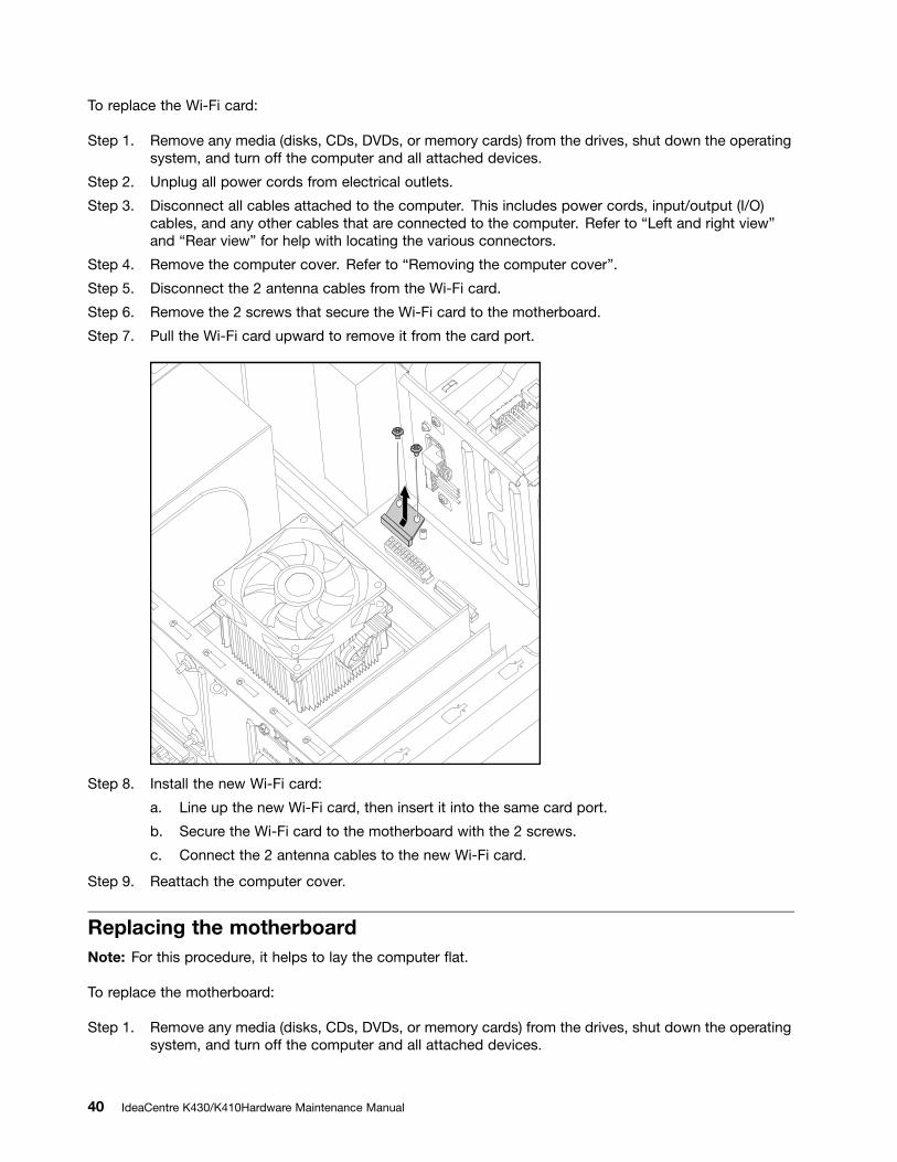


