Embed Size (px)
Citation preview

IDEA Connections user guide
IDEA RS s.r.o. | Jihomoravské inovační centrum, U Vodárny 2a, 616 00 BRNO
tel.: +420 - 511 205 263, fax: +420 - 541 143 011, www.idea-rs.cz, www.idea-rs.com
IDEA Connections
User guide
IDEA Connections user guide
IDEA RS s.r.o. | Jihomoravské inovační centrum, U Vodárny 2a, 616 00 BRNO
tel.: +420 - 511 205 263, fax: +420 - 541 143 011, www.idea-rs.cz, www.idea-rs.com
Content
1.1 Program requirements ...................................................................................................... 4
1.1 Installation guidelines ...................................................................................................... 4
2 User interface .......................................................................................................................... 5
2.1 3D view in the main window ........................................................................................... 5
2.1.1 Manipulating 3D view ............................................................................................... 6
3 Working with project .............................................................................................................. 8
3.1 Starting new project ......................................................................................................... 8
4 Joint input and design ............................................................................................................ 10
4.1 Project data ..................................................................................................................... 10
4.2 Joint geometry ................................................................................................................ 11
4.2.1 Ribbon group Member edit ..................................................................................... 12
4.3 Load effects .................................................................................................................... 13
4.3.1 Ribbon group Loads edit ......................................................................................... 14
4.3.2 Ribbon group Advanced mode ................................................................................ 14
4.4 Joint design and manufacturing operations .................................................................... 15
4.4.1 Cut ........................................................................................................................... 17
4.4.2 Stiffener ................................................................................................................... 20
4.4.3 Widener ................................................................................................................... 24
4.4.4 Rib ........................................................................................................................... 28
4.4.5 Opening ................................................................................................................... 31
4.4.6 Plate to plate ............................................................................................................ 33
4.4.7 End plate .................................................................................................................. 37
4.4.8 Shifted end plate ...................................................................................................... 42
4.4.9 Stub .......................................................................................................................... 45
4.4.10 Fin plate ................................................................................................................. 48
4.4.11 Gusset plate ........................................................................................................... 51
4.4.12 Base plate .............................................................................................................. 60
4.4.13 Splice ..................................................................................................................... 64
4.4.14 Connecting plate (hollow sections) ....................................................................... 70
4.4.15 Cleat ...................................................................................................................... 79
4.4.16 General plate ......................................................................................................... 83
4.4.17 Plate cut ................................................................................................................. 91
4.4.18 Fastener grid .......................................................................................................... 96
4.4.19 Weld ...................................................................................................................... 99
4.4.20 Welds properties .................................................................................................. 101
IDEA Connections user guide
IDEA RS s.r.o. | Jihomoravské inovační centrum, U Vodárny 2a, 616 00 BRNO
tel.: +420 - 511 205 263, fax: +420 - 541 143 011, www.idea-rs.cz, www.idea-rs.com
4.4.21 Input of bolts by layers ........................................................................................ 101
4.4.22 Input of bolt assembly ......................................................................................... 102
4.4.23 User defined templates of manufacturing operations .......................................... 103
4.4.24 Ribbon group Operations .................................................................................... 107
4.4.25 Ribbon group CBFEM ........................................................................................ 107
4.5 Plate editor .................................................................................................................... 109
4.5.1 Ribbon group Operations ...................................................................................... 109
5 Joint check ........................................................................................................................... 113
5.1 Analysis status .............................................................................................................. 114
5.2 Plates check .................................................................................................................. 115
5.3 Bolts check ................................................................................................................... 116
5.4 Concrete block check ................................................................................................... 118
5.5 Shear in contact plane check ........................................................................................ 119
5.6 Welds check ................................................................................................................. 120
5.7 Evaluation of joint stiffness .......................................................................................... 122
5.8 Evaluation of local buckling analysis ........................................................................... 123
5.9 Ribbon group CBFEM ................................................................................................. 124
5.10 Ribbon group FEM analysis ....................................................................................... 124
5.11 Report of current joint check ...................................................................................... 125
5.12 Bill of material of current joint .................................................................................. 126
5.13 National code and calculation settings ....................................................................... 127
5.14 Advanced FEM analysis settings ............................................................................... 129
6 Joints in project ................................................................................................................... 131
6.1 Ribbon group New item ............................................................................................... 132
6.2 Adding a new joint ....................................................................................................... 132
6.3 Calculation report ......................................................................................................... 133
6.4 One line report .......................................................................................................... 133
6.4.1 One page report ..................................................................................................... 133
6.5 Detailed report .......................................................................................................... 134
6.6 Ribbon group Report view ....................................................................................... 135
7 Materials, cross-sections and bolts in project ...................................................................... 136
7.1 Cross-sections ............................................................................................................... 136
7.2 Materials ....................................................................................................................... 138
7.3 Bolt assemblies ............................................................................................................. 139
IDEA Connections user guide 4
IDEA RS s.r.o. | Jihomoravské inovační centrum, U Vodárny 2a, 616 00 BRNO
tel.: +420 - 511 205 263, fax: +420 - 541 143 011, www.idea-rs.cz, www.idea-rs.com
1.1 Program requirements
Application requires .NET Framework 4.5 to be installed on your computer. You can
download it from web pages of Microsoft company.
(http://www.microsoft.com/downloads/details.aspx?displaylang=en&FamilyID=0a391abd-
25c1-4fc0-919f-b21f31ab88b7). In case of a missing .NET Framework 4 the installation will
not be launched.
1.1 Installation guidelines
IDEA Connections program is installed as a part of IDEA StatiCa package.
IDEA Connections user guide 5
IDEA RS s.r.o. | Jihomoravské inovační centrum, U Vodárny 2a, 616 00 BRNO
tel.: +420 - 511 205 263, fax: +420 - 541 143 011, www.idea-rs.cz, www.idea-rs.com
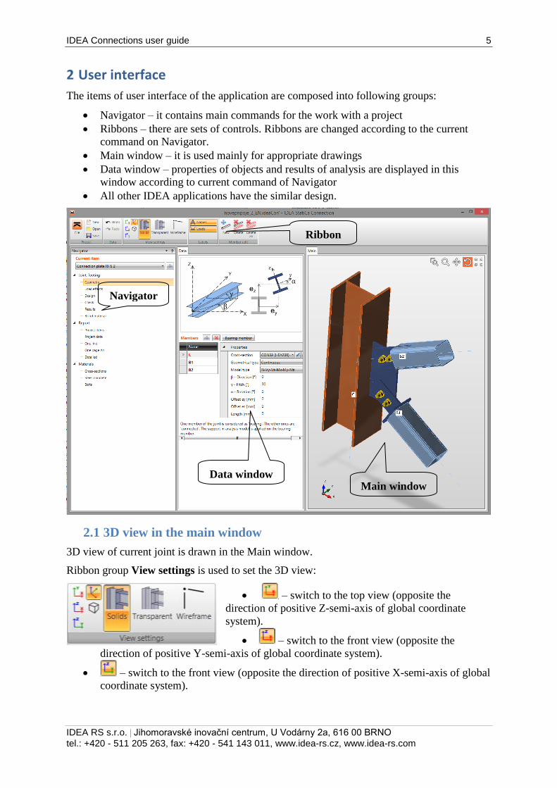
2 User interface
The items of user interface of the application are composed into following groups:
Navigator – it contains main commands for the work with a project
Ribbons – there are sets of controls. Ribbons are changed according to the current
command on Navigator.
Main window – it is used mainly for appropriate drawings
Data window – properties of objects and results of analysis are displayed in this
window according to current command of Navigator
All other IDEA applications have the similar design.
2.1 3D view in the main window
3D view of current joint is drawn in the Main window.
Ribbon group View settings is used to set the 3D view:
– switch to the top view (opposite the
direction of positive Z-semi-axis of global coordinate
system).
– switch to the front view (opposite the
direction of positive Y-semi-axis of global coordinate system).
– switch to the front view (opposite the direction of positive X-semi-axis of global
coordinate system).
Ribbon
Main window Data window
Navigator
IDEA Connections user guide 6
IDEA RS s.r.o. | Jihomoravské inovační centrum, U Vodárny 2a, 616 00 BRNO
tel.: +420 - 511 205 263, fax: +420 - 541 143 011, www.idea-rs.cz, www.idea-rs.com
– switch to the default 3D view and zooms the structure to fit into the main
window.
– switch on/off the perspective view mode.
Solids – switch to draw all joint items as solids respecting the edges visibility.
Transparent – switch to draw all joint items as transparent solids.
Wireframe – switch to draw only the axial scheme of joint members.
Ribbon group Labels is used to draw load effects and labels:
Names – switch on/off drawing of names of joint members.
Loads – switch on/off drawing of defined load effects in the
current load case.
Plates – switch on/off drawing of names of plates.
LCS – switch on/off drawing of local coordinate systems of members.
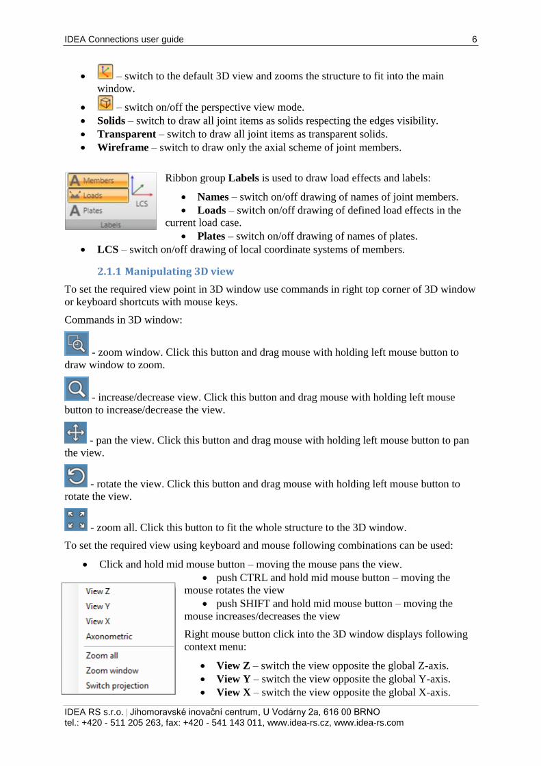
2.1.1 Manipulating 3D view
To set the required view point in 3D window use commands in right top corner of 3D window
or keyboard shortcuts with mouse keys.
Commands in 3D window:
- zoom window. Click this button and drag mouse with holding left mouse button to
draw window to zoom.
- increase/decrease view. Click this button and drag mouse with holding left mouse
button to increase/decrease the view.
- pan the view. Click this button and drag mouse with holding left mouse button to pan
the view.
- rotate the view. Click this button and drag mouse with holding left mouse button to
rotate the view.
- zoom all. Click this button to fit the whole structure to the 3D window.
To set the required view using keyboard and mouse following combinations can be used:
Click and hold mid mouse button – moving the mouse pans the view.
push CTRL and hold mid mouse button – moving the
mouse rotates the view
push SHIFT and hold mid mouse button – moving the
mouse increases/decreases the view
Right mouse button click into the 3D window displays following
context menu:
View Z – switch the view opposite the global Z-axis.
View Y – switch the view opposite the global Y-axis.
View X – switch the view opposite the global X-axis.
IDEA Connections user guide 7
IDEA RS s.r.o. | Jihomoravské inovační centrum, U Vodárny 2a, 616 00 BRNO
tel.: +420 - 511 205 263, fax: +420 - 541 143 011, www.idea-rs.cz, www.idea-rs.com
Zoom all – zoom the view to fit the whole structure.
Zoom window – zoom the defined rectangular area.
Switch projection – switch between the axonometric and perspective view.
IDEA Connections user guide 8
IDEA RS s.r.o. | Jihomoravské inovační centrum, U Vodárny 2a, 616 00 BRNO
tel.: +420 - 511 205 263, fax: +420 - 541 143 011, www.idea-rs.cz, www.idea-rs.com
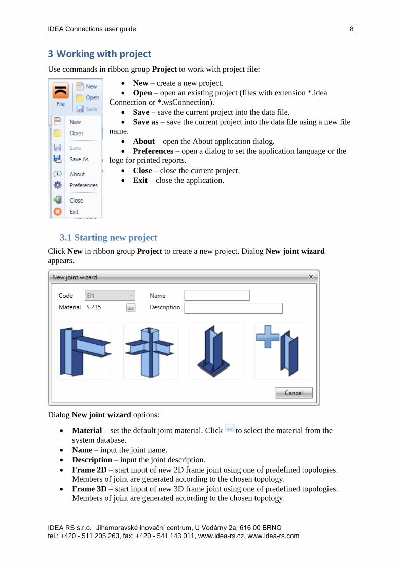
3 Working with project
Use commands in ribbon group Project to work with project file:
New – create a new project.
Open – open an existing project (files with extension *.idea
Connection or *.wsConnection).
Save – save the current project into the data file.
Save as – save the current project into the data file using a new file
name.
About – open the About application dialog.
Preferences – open a dialog to set the application language or the
logo for printed reports.
Close – close the current project.
Exit – close the application.
3.1 Starting new project
Click New in ribbon group Project to create a new project. Dialog New joint wizard
appears.
Dialog New joint wizard options:
Material – set the default joint material. Click to select the material from the
system database.
Name – input the joint name.
Description – input the joint description.
Frame 2D – start input of new 2D frame joint using one of predefined topologies.
Members of joint are generated according to the chosen topology.
Frame 3D – start input of new 3D frame joint using one of predefined topologies.
Members of joint are generated according to the chosen topology.

IDEA Connections user guide 9
IDEA RS s.r.o. | Jihomoravské inovační centrum, U Vodárny 2a, 616 00 BRNO
tel.: +420 - 511 205 263, fax: +420 - 541 143 011, www.idea-rs.cz, www.idea-rs.com
Anchor - start input of new anchor joint using one of predefined topologies. Members
of joint are generated according to the chosen topology.
General – start input of new general joint. Individual members of joint must be
defined manually.
IDEA Connections user guide 10
IDEA RS s.r.o. | Jihomoravské inovační centrum, U Vodárny 2a, 616 00 BRNO
tel.: +420 - 511 205 263, fax: +420 - 541 143 011, www.idea-rs.cz, www.idea-rs.com
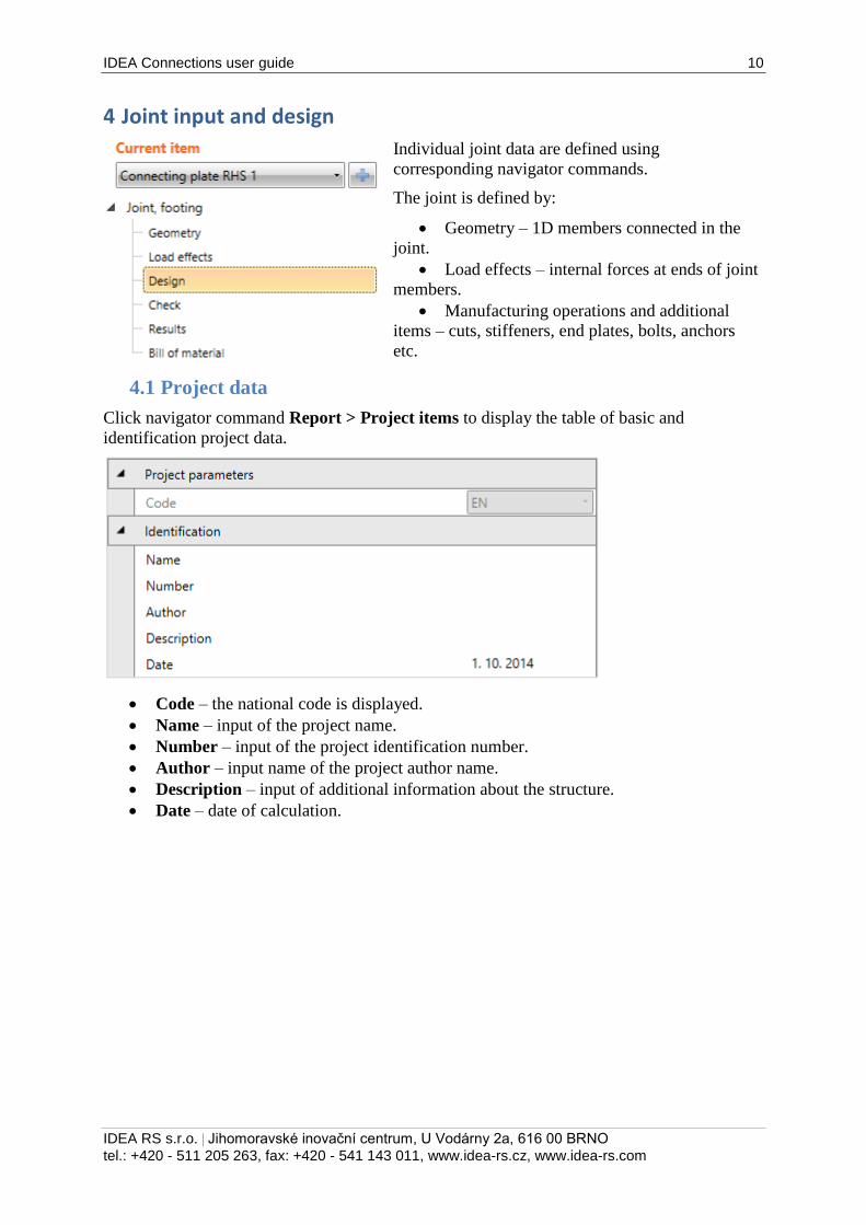
4 Joint input and design
Individual joint data are defined using
corresponding navigator commands.
The joint is defined by:
Geometry – 1D members connected in the
joint.
Load effects – internal forces at ends of joint
members.
Manufacturing operations and additional
items – cuts, stiffeners, end plates, bolts, anchors
etc.
4.1 Project data
Click navigator command Report > Project items to display the table of basic and
identification project data.
Code – the national code is displayed.
Name – input of the project name.
Number – input of the project identification number.
Author – input name of the project author name.
Description – input of additional information about the structure.
Date – date of calculation.
IDEA Connections user guide 11
IDEA RS s.r.o. | Jihomoravské inovační centrum, U Vodárny 2a, 616 00 BRNO
tel.: +420 - 511 205 263, fax: +420 - 541 143 011, www.idea-rs.cz, www.idea-rs.com
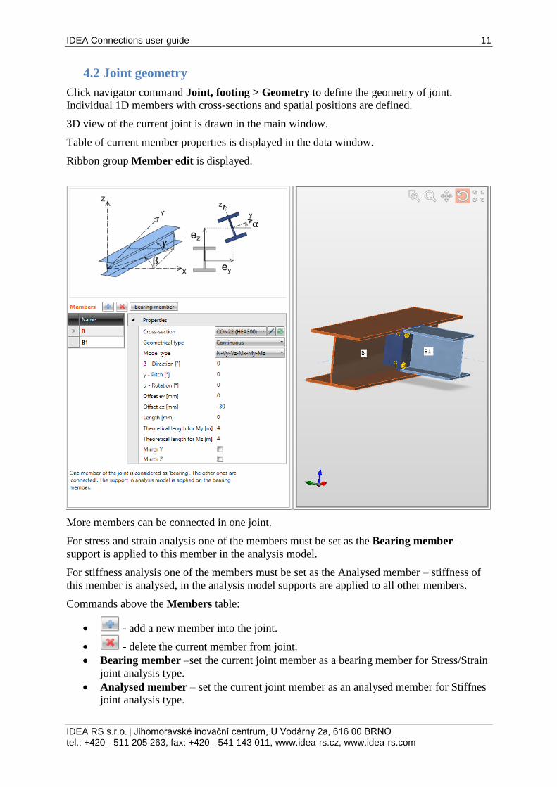
4.2 Joint geometry
Click navigator command Joint, footing > Geometry to define the geometry of joint.
Individual 1D members with cross-sections and spatial positions are defined.
3D view of the current joint is drawn in the main window.
Table of current member properties is displayed in the data window.
Ribbon group Member edit is displayed.
More members can be connected in one joint.
For stress and strain analysis one of the members must be set as the Bearing member –
support is applied to this member in the analysis model.
For stiffness analysis one of the members must be set as the Analysed member – stiffness of
this member is analysed, in the analysis model supports are applied to all other members.
Commands above the Members table:
- add a new member into the joint.
- delete the current member from joint.
Bearing member –set the current joint member as a bearing member for Stress/Strain
joint analysis type.
Analysed member – set the current joint member as an analysed member for Stiffnes
joint analysis type.
IDEA Connections user guide 12
IDEA RS s.r.o. | Jihomoravské inovační centrum, U Vodárny 2a, 616 00 BRNO
tel.: +420 - 511 205 263, fax: +420 - 541 143 011, www.idea-rs.cz, www.idea-rs.com
List of joint members is displayed in the Members table:
Name – input the name of the current member. The name of bearing (analysed)
member is highlighted.
The table of member properties is displayed for the current member:
Cross-section - assign the selected cross-section to the member. Cross-section can be
selected from the list of all available cross-sections. Click to change cross-section
parameters. Click to add a new cross-section and assign it to the appropriate
member.
Type of geometry – select the geometrical model of member:
o Continuous – the member is continuous – it means that the mid of the member
is placed into the theoretical centre of joint.
o Ended – the end of the member is placed into the theoretical centre of joint.
Model type – select the physical model of the member:
o N –member can transfer forces only in the direction of local x-axis – normal
force N.
o N-Vz-My – member can transfer forces only in xz -plane of local axes –
normal force N, shear force Vz, bending moment My.
o N-Vy_Mz – member can transfer forces only in xy -plane of local axes –
normal force N, shear force Vy, bending moment Mz.
o N-Vy-Vz-Mx-My-Mz – member can transfer forces in all directions.
β – direction – input the rotation of member about Z-axis of global coordinate system
(the direction of member in global XY-plane).
γ – pitch – input the angle between the member x-axis and the XY-plane of global
coordinate system.
α – rotation – input the rotation of the member about the local x-axis of the member.
Offset ey – input of offset (eccentricity) of the current member in the direction of y-
axis of local coordinate system of the member.
Offset ez – input of offset (eccentricity) of the current member in the direction of z-
axis of local coordinate system of the member.
Length – input of the length of member. Value 0 means that the length is calculated
automatically according to the height of cross-section.
Theoretical length My – input of theoretical length for stiffness classification.
Theoretical length Mz – input of theoretical length for stiffness classification.
Mirror Y – if selected, the cross-section of member is mirrored according to plane
XY of local coordinate system of member.
Mirror Z – if selected, the cross-section of member is mirrored according to plane XZ
of local coordinate system of member.
4.2.1 Ribbon group Member edit
New – add a new member into the joint.
Delete – delete the current member from the joint.
Delete all – delete all members from the joint.
IDEA Connections user guide 13
IDEA RS s.r.o. | Jihomoravské inovační centrum, U Vodárny 2a, 616 00 BRNO
tel.: +420 - 511 205 263, fax: +420 - 541 143 011, www.idea-rs.cz, www.idea-rs.com
4.3 Load effects
Click navigator command Joint, footing > Load effects to input values of load effects
(internal forces) in the joint.
The joint is loaded by load effects (internal forces) acting on individual members of joint. The
load effects are assigned to groups – load cases. More load cases can be defined in one joint.
The calculation and check is performed separately per each defined load case.
Load effects may be defined in one of following modes:
Complete input of load effects on all members. Load effects equilibrium is checked.
Limited input only on connected members. Load effect cannot be defined on bearing
member. Bearing member is fully supported, continuous member is supported on
ends.
The mode of load effects definition can be selected in ribbon group Advanced mode.
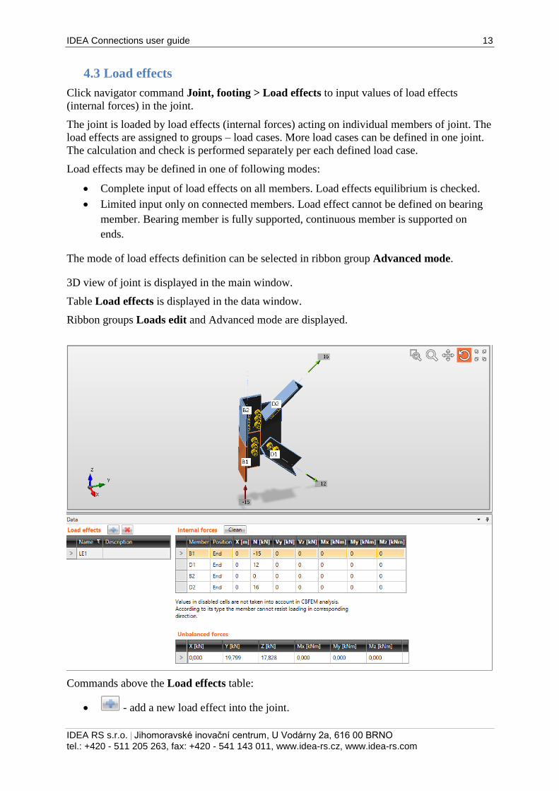
3D view of joint is displayed in the main window.
Table Load effects is displayed in the data window.
Ribbon groups Loads edit and Advanced mode are displayed.
Commands above the Load effects table:
- add a new load effect into the joint.
IDEA Connections user guide 14
IDEA RS s.r.o. | Jihomoravské inovační centrum, U Vodárny 2a, 616 00 BRNO
tel.: +420 - 511 205 263, fax: +420 - 541 143 011, www.idea-rs.cz, www.idea-rs.com
- delete the current load effect from the joint.
Columns in the Load effect table:
Name – input name of load effects group.
Description – input description of load effects group.
Values of internal forces on ends of individual members are defined in the Internal forces
table.
Columns in Internal forces table:
Member – name of member is displayed.
Position – position of load effect on individual member is displayed.
X - input of distance of force from the beginning of joint.
N – input of axial force in the direction of x-axis of the member local coordinate
system.
Vy – input of shear force in the direction of y-axis of the member local coordinate
system.
Vz – input of shear force in the direction of z-axis of the member local coordinate
system.
Mx – input of torsional moment about x-axis of the member local coordinate system.
My – input of bending moment about y-axis of the member local coordinate system.
Mz – input of bending moment about z-axis of the member local coordinate system.
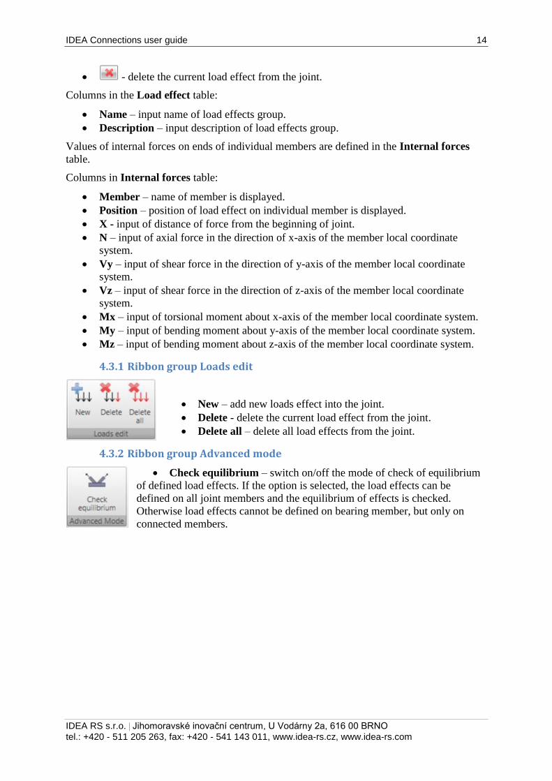
4.3.1 Ribbon group Loads edit
New – add new loads effect into the joint.
Delete - delete the current load effect from the joint.
Delete all – delete all load effects from the joint.
4.3.2 Ribbon group Advanced mode
Check equilibrium – switch on/off the mode of check of equilibrium
of defined load effects. If the option is selected, the load effects can be
defined on all joint members and the equilibrium of effects is checked.
Otherwise load effects cannot be defined on bearing member, but only on
connected members.
IDEA Connections user guide 15
IDEA RS s.r.o. | Jihomoravské inovační centrum, U Vodárny 2a, 616 00 BRNO
tel.: +420 - 511 205 263, fax: +420 - 541 143 011, www.idea-rs.cz, www.idea-rs.com
4.4 Joint design and manufacturing operations
The joint design consists of several manufacturing operations, which modify the shape of
members and create additional items required for proper joint check (cuts, end plates,
stiffeners, bolts, anchors etc.). Click navigator command Joint, footing > Design to design
the joint.
3D view of joint is displayed in the main window.
Table Manufacturing operations is displayed in the data window.
Ribbon groups Operations and CBFEM are displayed.
Commands above the table Manufacturing operations:
- add a new manufacturing operation into the joint.
- delete the current manufacturing operation from the joint.
Delete all – delete all manufacturing operations from the joint.
Calculate – start analysis of the joint.
Editor – launch plates editor. This command is available only for operations, which
create plates.
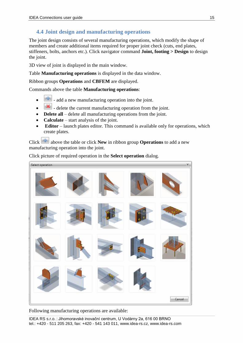
Click above the table or click New in ribbon group Operations to add a new
manufacturing operation into the joint.
Click picture of required operation in the Select operation dialog.
Following manufacturing operations are available:
IDEA Connections user guide 16
IDEA RS s.r.o. | Jihomoravské inovační centrum, U Vodárny 2a, 616 00 BRNO
tel.: +420 - 511 205 263, fax: +420 - 541 143 011, www.idea-rs.cz, www.idea-rs.com
Cut – see 4.4.1 Cut.
Stiffener – 4.4.2 Stiffener.
Widener – see 4.4.3 Widener.
Rib - see 4.4.4 Rib.
Opening – see 4.4.5 Opening.
End plate – see 4.4.7 End plate.
Shifted end plate – see 4.4.8 Shifted end plate.
Stub – see 4.4.9 Stub.
Plate to plate – see 4.4.6 Plate to plate.
Splice – see 4.4.14 Splice.
Gusset plate – see 4.4.11 Gusset plate.
Connecting plate for hollow sections – see 4.4.16 Connecting plate (hollow
sections).Fin plate – see 4.4.10 Fin plate.
Cleat – see 4.4.18 Cleat.
Base plate – see 4.4.13 Base plate.
General plate – see 4.4.20 General plate.
Plate cut – see 4.4.21 Plate cut.
Fasteners grid – see 4.4.22 Fastener grid
General weld – see 4.4.24 Weld
IDEA Connections user guide 17
IDEA RS s.r.o. | Jihomoravské inovační centrum, U Vodárny 2a, 616 00 BRNO
tel.: +420 - 511 205 263, fax: +420 - 541 143 011, www.idea-rs.cz, www.idea-rs.com
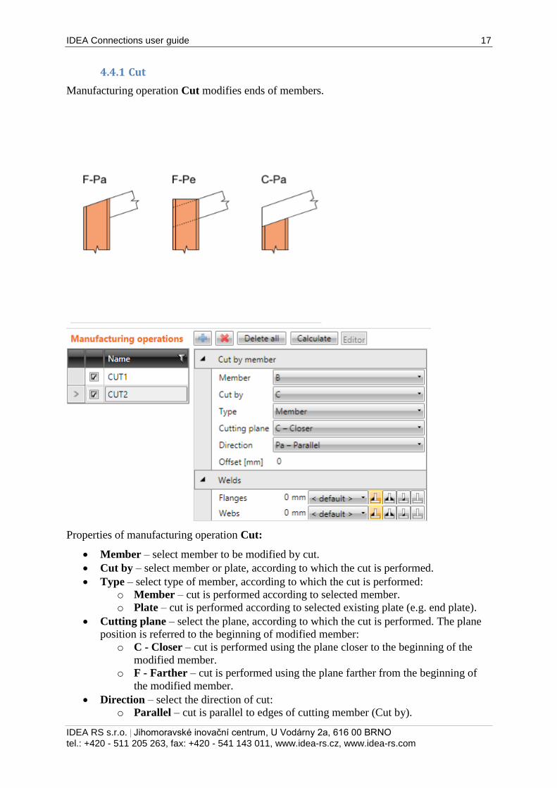
4.4.1 Cut
Manufacturing operation Cut modifies ends of members.
Properties of manufacturing operation Cut:
Member – select member to be modified by cut.
Cut by – select member or plate, according to which the cut is performed.
Type – select type of member, according to which the cut is performed:
o Member – cut is performed according to selected member.
o Plate – cut is performed according to selected existing plate (e.g. end plate).
Cutting plane – select the plane, according to which the cut is performed. The plane
position is referred to the beginning of modified member:
o C - Closer – cut is performed using the plane closer to the beginning of the
modified member.
o F - Farther – cut is performed using the plane farther from the beginning of
the modified member.
Direction – select the direction of cut:
o Parallel – cut is parallel to edges of cutting member (Cut by).
IDEA Connections user guide 18
IDEA RS s.r.o. | Jihomoravské inovační centrum, U Vodárny 2a, 616 00 BRNO
tel.: +420 - 511 205 263, fax: +420 - 541 143 011, www.idea-rs.cz, www.idea-rs.com
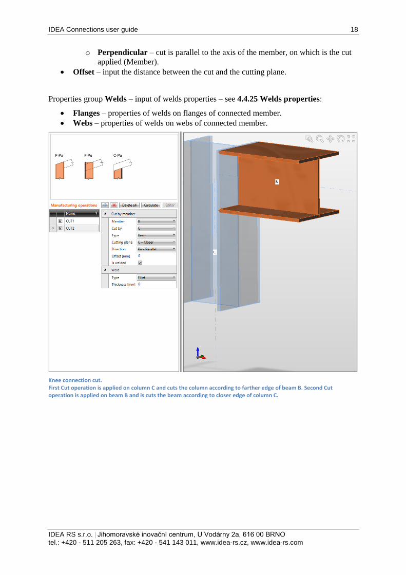
o Perpendicular – cut is parallel to the axis of the member, on which is the cut
applied (Member).
Offset – input the distance between the cut and the cutting plane.
Properties group Welds – input of welds properties – see 4.4.25 Welds properties:
Flanges – properties of welds on flanges of connected member.
Webs – properties of welds on webs of connected member.
Knee connection cut. First Cut operation is applied on column C and cuts the column according to farther edge of beam B. Second Cut operation is applied on beam B and is cuts the beam according to closer edge of column C.
IDEA Connections user guide 19
IDEA RS s.r.o. | Jihomoravské inovační centrum, U Vodárny 2a, 616 00 BRNO
tel.: +420 - 511 205 263, fax: +420 - 541 143 011, www.idea-rs.cz, www.idea-rs.com
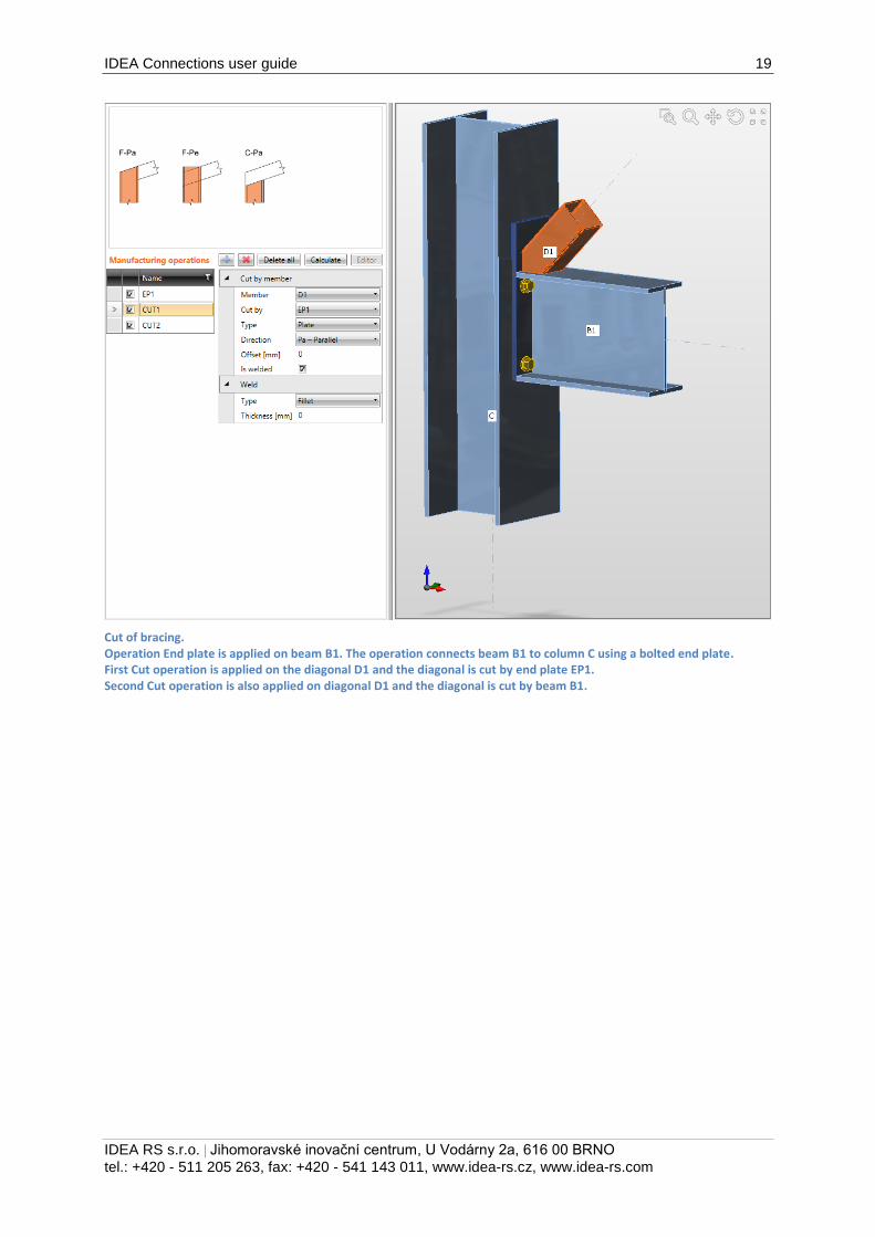
Cut of bracing. Operation End plate is applied on beam B1. The operation connects beam B1 to column C using a bolted end plate. First Cut operation is applied on the diagonal D1 and the diagonal is cut by end plate EP1. Second Cut operation is also applied on diagonal D1 and the diagonal is cut by beam B1.
IDEA Connections user guide 20
IDEA RS s.r.o. | Jihomoravské inovační centrum, U Vodárny 2a, 616 00 BRNO
tel.: +420 - 511 205 263, fax: +420 - 541 143 011, www.idea-rs.cz, www.idea-rs.com
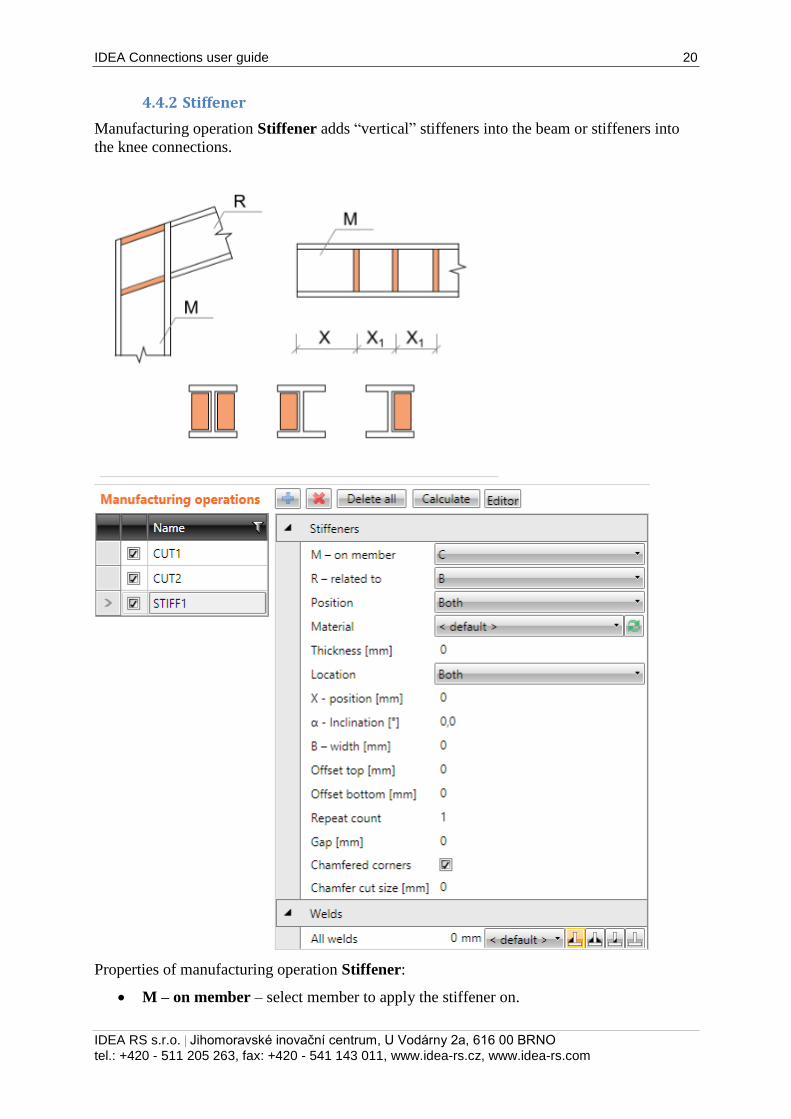
4.4.2 Stiffener
Manufacturing operation Stiffener adds “vertical” stiffeners into the beam or stiffeners into
the knee connections.
Properties of manufacturing operation Stiffener:
M – on member – select member to apply the stiffener on.
IDEA Connections user guide 21
IDEA RS s.r.o. | Jihomoravské inovační centrum, U Vodárny 2a, 616 00 BRNO
tel.: +420 - 511 205 263, fax: +420 - 541 143 011, www.idea-rs.cz, www.idea-rs.com
R – related to – select member, to which the stiffener is also related. The “Related to”
member is required to define the direction of stiffener in frame knee.
Position – select position of stiffener in knee connection:
o Upper – stiffener is positioned to the upper edge of cross-section of “Related
to” member.
o Lower – stiffener is positioned to the lower edge of cross-section of “Related
to” member.
o Both – stiffeners are positioned to both edges of cross-section of “Related to”
member.
o Centre – stiffener is positioned to the centre of height of cross-section of
“Related to” member.
Material – select material of stiffener. Member material is taken as default.
Thickness – input thickness of stiffener. Value 0 means, that the plate thickness is
determined according to the cross-section.
Location – select side location of stiffener:
o Both – stiffener is located on both sides of modified member.
o Front – stiffener is located on one side of modified member.
o Rear – stiffener is located on the other side of modified member.
X – position – input of plate position related to the beginning of modified member or
to origin according to defined position of stiffener to the “Related to” member.
α – inclination – input of stiffener inclination related to the axis of modified member.
B – width – input of stiffener width. Value 0 means, that the width is determined
automatically according to the cross-section of modified member.
Offset top – input of offset of top edge of stiffener from the flange of member. The
stiffener edge with nonzero offset is not welded to cross-section flange.
Offset bottom – input of offset of bottom edge of stiffener from the flange of
member. The stiffener edge with nonzero offset is not welded to cross-section flange.
Repeat count – input of count of repeated stiffeners.
Xd – delta x – input of distance between repeated stiffeners.
Gap – input of distance between stiffener edges and edges of cross-section of
modified member. The stiffener is welded to cross-section in the gap area.
Chamfered corners – switch on/off chamfers of stiffener corners (between flange and
web of modified member).
Chamfer cut size – input the length of cut along edges (from the corner). Value 0
means, that the length of cut is determined automatically according to the cross-
section (only for rolled sections).
Properties group Welds – input of welds properties – see 4.4.25 Welds properties:
All welds – properties of all stiffener welds.
IDEA Connections user guide 22
IDEA RS s.r.o. | Jihomoravské inovační centrum, U Vodárny 2a, 616 00 BRNO
tel.: +420 - 511 205 263, fax: +420 - 541 143 011, www.idea-rs.cz, www.idea-rs.com
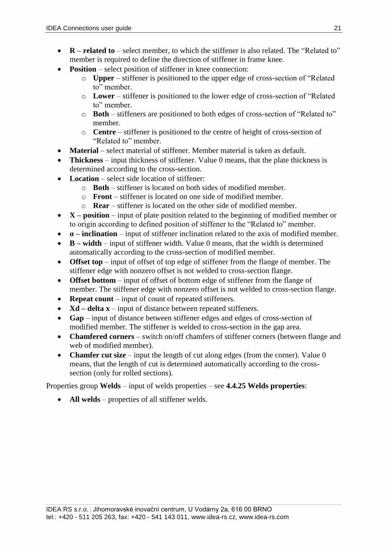
Stiffener in the knee connection. First manufacturing operation Cut is defined on member C, to cut the column according to the farther edge of beam B. Second manufacturing operation Cut is defined on beam B, to cut the beam B according to the closer edge of column C. Manufacturing operation Stiffener is defined on column C. The stiffener is related also to the beam B – to respect the inclination of beam B.
IDEA Connections user guide 23
IDEA RS s.r.o. | Jihomoravské inovační centrum, U Vodárny 2a, 616 00 BRNO
tel.: +420 - 511 205 263, fax: +420 - 541 143 011, www.idea-rs.cz, www.idea-rs.com
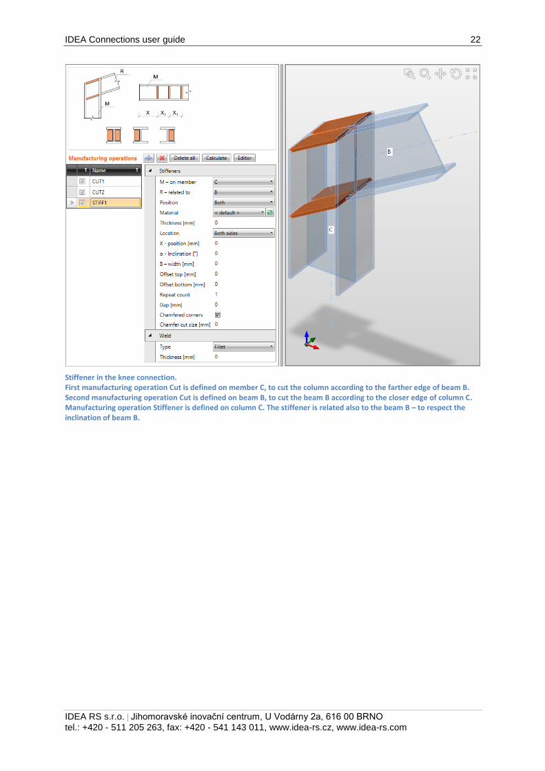
Stiffeners on beam. Manufacturing operation Stiffener is defined on beam B. The stiffener is both-sided and repeated along the beam.
IDEA Connections user guide 24
IDEA RS s.r.o. | Jihomoravské inovační centrum, U Vodárny 2a, 616 00 BRNO
tel.: +420 - 511 205 263, fax: +420 - 541 143 011, www.idea-rs.cz, www.idea-rs.com
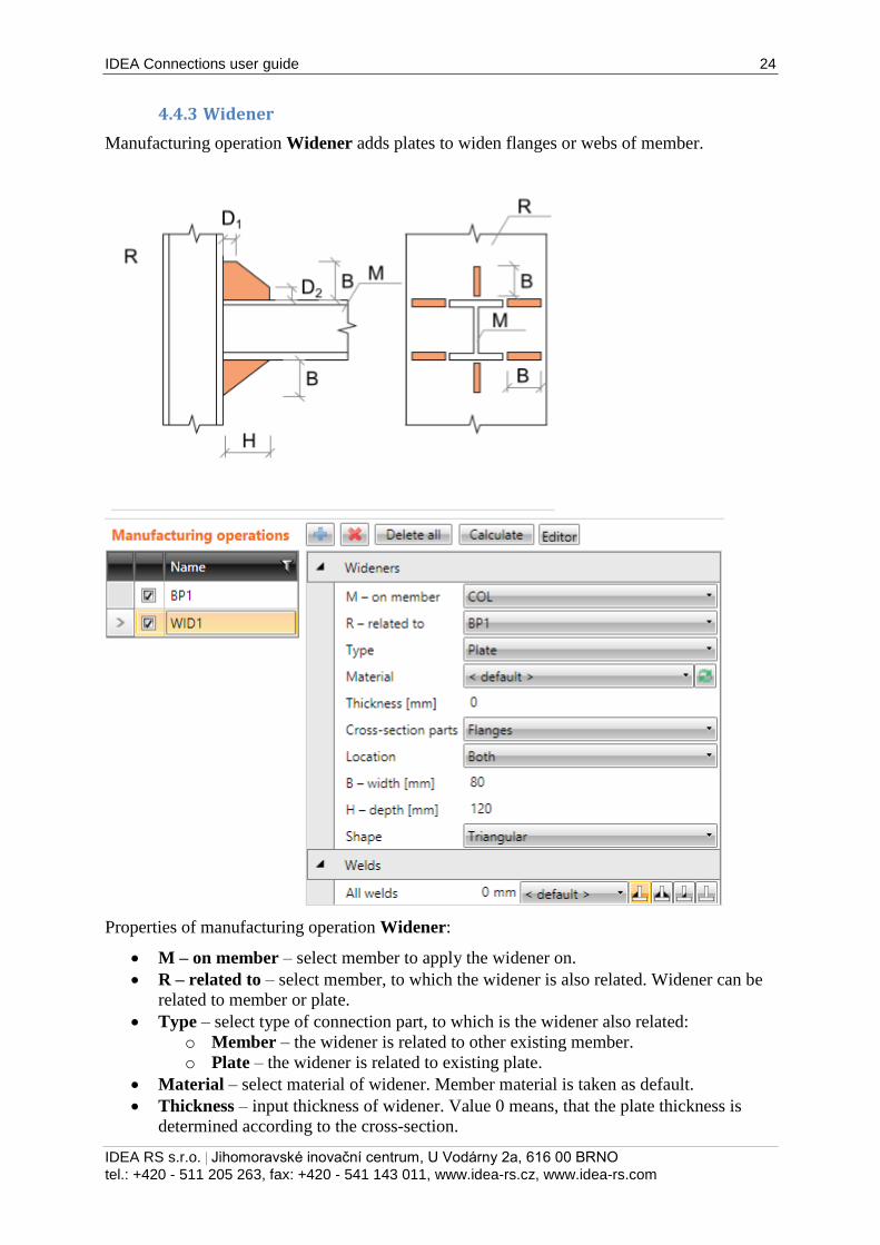
4.4.3 Widener
Manufacturing operation Widener adds plates to widen flanges or webs of member.
Properties of manufacturing operation Widener:
M – on member – select member to apply the widener on.
R – related to – select member, to which the widener is also related. Widener can be
related to member or plate.
Type – select type of connection part, to which is the widener also related:
o Member – the widener is related to other existing member.
o Plate – the widener is related to existing plate.
Material – select material of widener. Member material is taken as default.
Thickness – input thickness of widener. Value 0 means, that the plate thickness is
determined according to the cross-section.
IDEA Connections user guide 25
IDEA RS s.r.o. | Jihomoravské inovační centrum, U Vodárny 2a, 616 00 BRNO
tel.: +420 - 511 205 263, fax: +420 - 541 143 011, www.idea-rs.cz, www.idea-rs.com
Cross-section parts – select the cross-section part, on which the widener is applied:
o All parts – widener is applied on all flanges and webs of cross-section of
modified member.
o Flanges – widener is applied on all flanges of cross-section of modified
member.
o Bottom flange – widener is applied on bottom flange of cross-section of
modified member.
o Top flange – widener is applied on top flange of cross-section of modified
member.
o Webs – widener is applied on webs of cross-section of modified member.
Location – side location of widener:
o Front – widener is applied on one side of selected cross-section part.
o Rear – widener is applied on the other side of selected cross-section part.
o Both – widener is applied on both sides of selected cross-section part.
B – width – input width of widener (length on “Related to” member).
H – height – input height of widener (length on modified member).
Shape – select shape of widener:
o Rectangular – the widener is rectangular.
o Triangular – the widener is triangular.
o Chamfered – the widener is rectangular with chamfered corners. The chamfer
dimensions are defined by:
D1 – input chamfer length along “Related to” member.
D2 – input chamfer length along modified member.
o Triangular with flange – the widener is rectangular with welded flange. The
widener flange is defined by:
TF – flange thickness – input thickness of widener flange.
BF – flange width – input width of widener flange.
Properties group Welds – input of welds properties – see 4.4.25 Welds properties:
All welds – properties of all welds of widener.
IDEA Connections user guide 26
IDEA RS s.r.o. | Jihomoravské inovační centrum, U Vodárny 2a, 616 00 BRNO
tel.: +420 - 511 205 263, fax: +420 - 541 143 011, www.idea-rs.cz, www.idea-rs.com
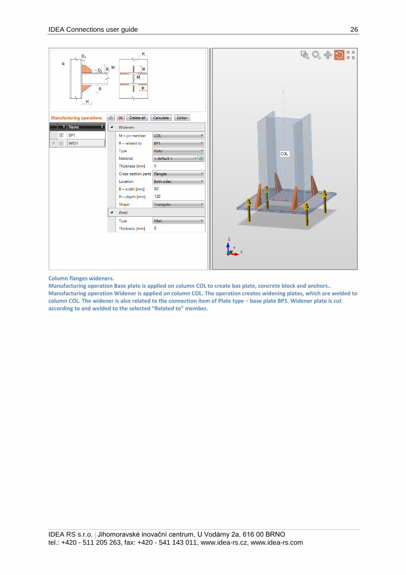
Column flanges wideners. Manufacturing operation Base plate is applied on column COL to create bas plate, concrete block and anchors.. Manufacturing operation Widener is applied on column COL. The operation creates widening plates, which are welded to column COL. The widener is also related to the connection item of Plate type – base plate BP1. Widener plate is cut according to and welded to the selected “Related to” member.
IDEA Connections user guide 27
IDEA RS s.r.o. | Jihomoravské inovační centrum, U Vodárny 2a, 616 00 BRNO
tel.: +420 - 511 205 263, fax: +420 - 541 143 011, www.idea-rs.cz, www.idea-rs.com
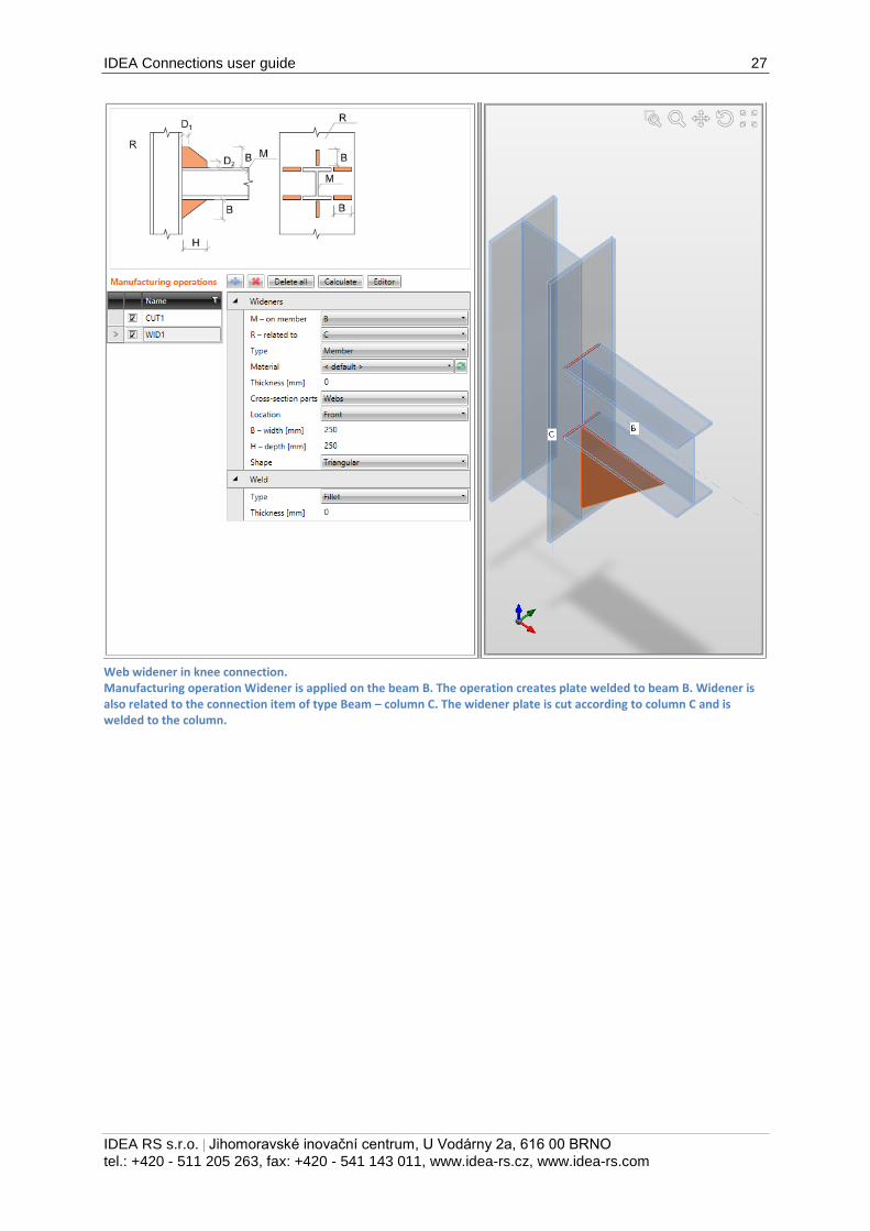
Web widener in knee connection. Manufacturing operation Widener is applied on the beam B. The operation creates plate welded to beam B. Widener is also related to the connection item of type Beam – column C. The widener plate is cut according to column C and is welded to the column.
IDEA Connections user guide 28
IDEA RS s.r.o. | Jihomoravské inovační centrum, U Vodárny 2a, 616 00 BRNO
tel.: +420 - 511 205 263, fax: +420 - 541 143 011, www.idea-rs.cz, www.idea-rs.com
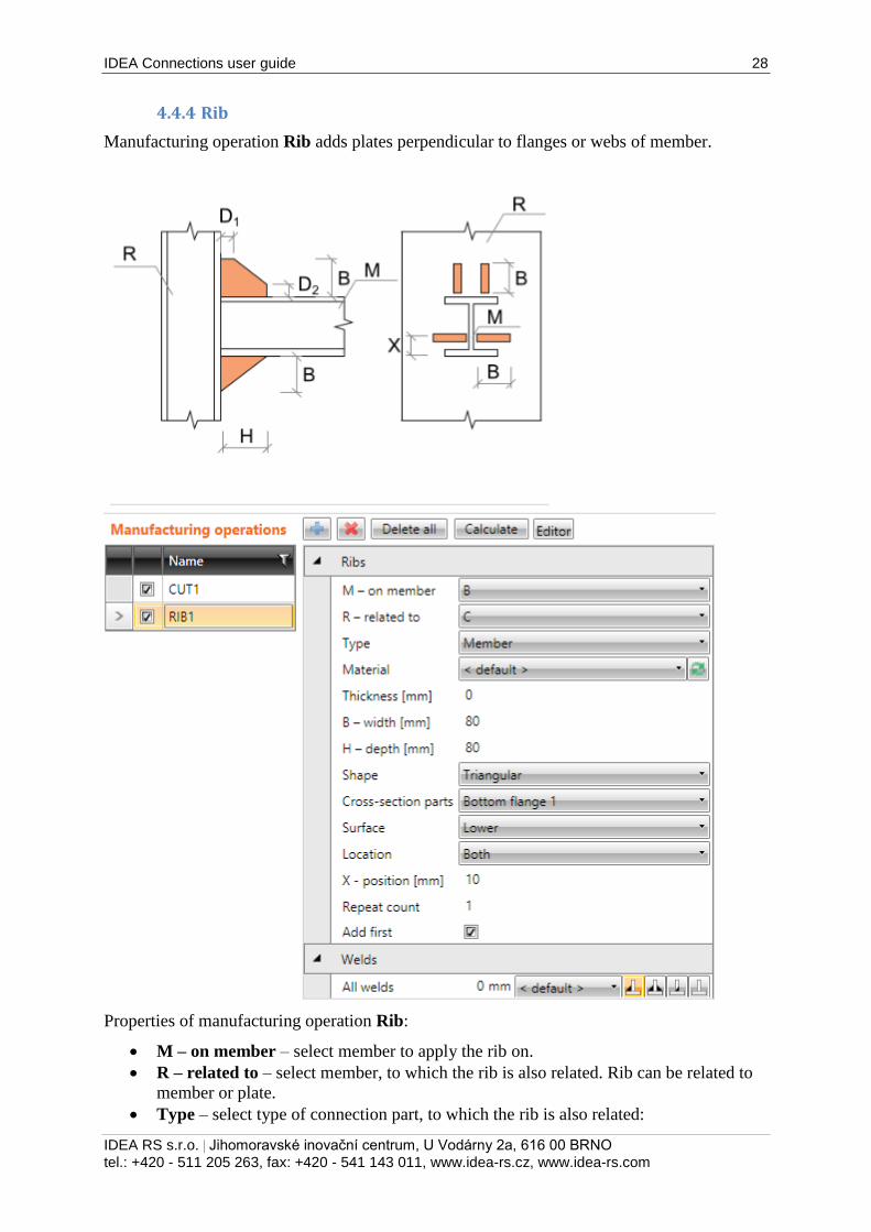
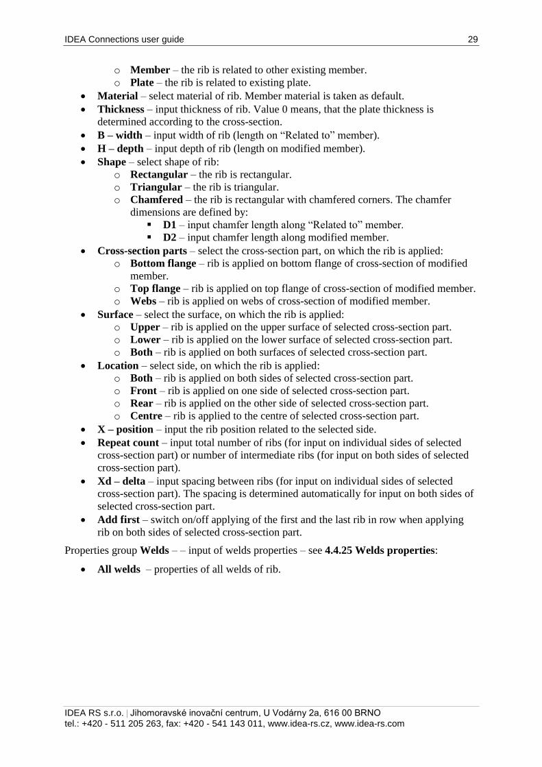
4.4.4 Rib
Manufacturing operation Rib adds plates perpendicular to flanges or webs of member.
Properties of manufacturing operation Rib:
M – on member – select member to apply the rib on.
R – related to – select member, to which the rib is also related. Rib can be related to
member or plate.
Type – select type of connection part, to which the rib is also related:
IDEA Connections user guide 29
IDEA RS s.r.o. | Jihomoravské inovační centrum, U Vodárny 2a, 616 00 BRNO
tel.: +420 - 511 205 263, fax: +420 - 541 143 011, www.idea-rs.cz, www.idea-rs.com
o Member – the rib is related to other existing member.
o Plate – the rib is related to existing plate.
Material – select material of rib. Member material is taken as default.
Thickness – input thickness of rib. Value 0 means, that the plate thickness is
determined according to the cross-section.
B – width – input width of rib (length on “Related to” member).
H – depth – input depth of rib (length on modified member).
Shape – select shape of rib:
o Rectangular – the rib is rectangular.
o Triangular – the rib is triangular.
o Chamfered – the rib is rectangular with chamfered corners. The chamfer
dimensions are defined by:
D1 – input chamfer length along “Related to” member.
D2 – input chamfer length along modified member.
Cross-section parts – select the cross-section part, on which the rib is applied:
o Bottom flange – rib is applied on bottom flange of cross-section of modified
member.
o Top flange – rib is applied on top flange of cross-section of modified member.
o Webs – rib is applied on webs of cross-section of modified member.
Surface – select the surface, on which the rib is applied:
o Upper – rib is applied on the upper surface of selected cross-section part.
o Lower – rib is applied on the lower surface of selected cross-section part.
o Both – rib is applied on both surfaces of selected cross-section part.
Location – select side, on which the rib is applied:
o Both – rib is applied on both sides of selected cross-section part.
o Front – rib is applied on one side of selected cross-section part.
o Rear – rib is applied on the other side of selected cross-section part.
o Centre – rib is applied to the centre of selected cross-section part.
X – position – input the rib position related to the selected side.
Repeat count – input total number of ribs (for input on individual sides of selected
cross-section part) or number of intermediate ribs (for input on both sides of selected
cross-section part).
Xd – delta – input spacing between ribs (for input on individual sides of selected
cross-section part). The spacing is determined automatically for input on both sides of
selected cross-section part.
Add first – switch on/off applying of the first and the last rib in row when applying
rib on both sides of selected cross-section part.
Properties group Welds – – input of welds properties – see 4.4.25 Welds properties:
All welds – properties of all welds of rib.
IDEA Connections user guide 30
IDEA RS s.r.o. | Jihomoravské inovační centrum, U Vodárny 2a, 616 00 BRNO
tel.: +420 - 511 205 263, fax: +420 - 541 143 011, www.idea-rs.cz, www.idea-rs.com
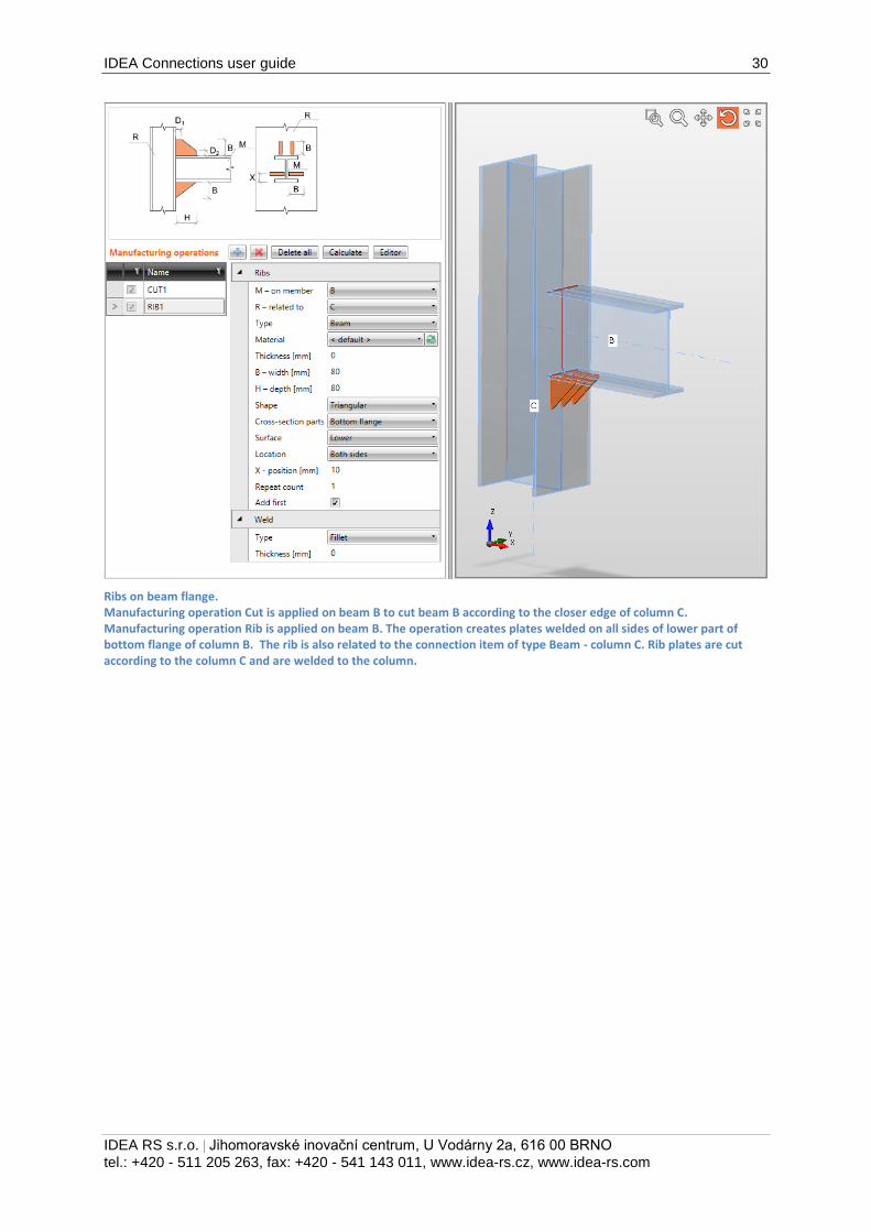
Ribs on beam flange. Manufacturing operation Cut is applied on beam B to cut beam B according to the closer edge of column C. Manufacturing operation Rib is applied on beam B. The operation creates plates welded on all sides of lower part of bottom flange of column B. The rib is also related to the connection item of type Beam - column C. Rib plates are cut according to the column C and are welded to the column.
IDEA Connections user guide 31
IDEA RS s.r.o. | Jihomoravské inovační centrum, U Vodárny 2a, 616 00 BRNO
tel.: +420 - 511 205 263, fax: +420 - 541 143 011, www.idea-rs.cz, www.idea-rs.com
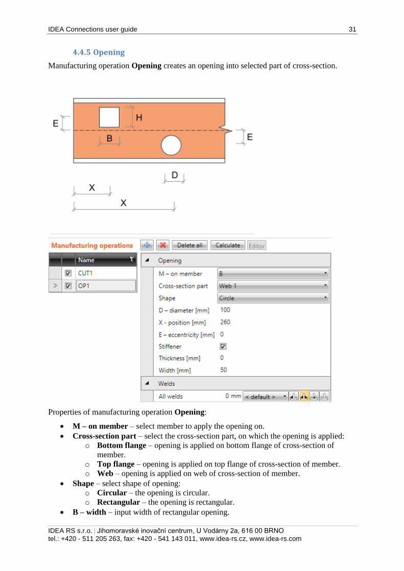
4.4.5 Opening
Manufacturing operation Opening creates an opening into selected part of cross-section.
Properties of manufacturing operation Opening:
M – on member – select member to apply the opening on.
Cross-section part – select the cross-section part, on which the opening is applied:
o Bottom flange – opening is applied on bottom flange of cross-section of
member.
o Top flange – opening is applied on top flange of cross-section of member.
o Web – opening is applied on web of cross-section of member.
Shape – select shape of opening:
o Circular – the opening is circular.
o Rectangular – the opening is rectangular.
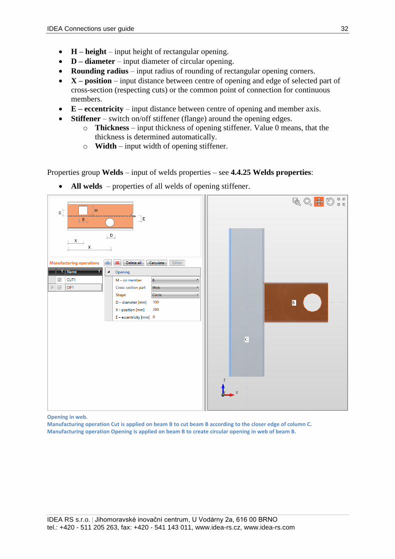
B – width – input width of rectangular opening.
IDEA Connections user guide 32
IDEA RS s.r.o. | Jihomoravské inovační centrum, U Vodárny 2a, 616 00 BRNO
tel.: +420 - 511 205 263, fax: +420 - 541 143 011, www.idea-rs.cz, www.idea-rs.com
H – height – input height of rectangular opening.
D – diameter – input diameter of circular opening.
Rounding radius – input radius of rounding of rectangular opening corners.
X – position – input distance between centre of opening and edge of selected part of
cross-section (respecting cuts) or the common point of connection for continuous
members.
E – eccentricity – input distance between centre of opening and member axis.
Stiffener – switch on/off stiffener (flange) around the opening edges.
o Thickness – input thickness of opening stiffener. Value 0 means, that the
thickness is determined automatically.
o Width – input width of opening stiffener.
Properties group Welds – input of welds properties – see 4.4.25 Welds properties:
All welds – properties of all welds of opening stiffener.
Opening in web. Manufacturing operation Cut is applied on beam B to cut beam B according to the closer edge of column C. Manufacturing operation Opening is applied on beam B to create circular opening in web of beam B.
IDEA Connections user guide 33
IDEA RS s.r.o. | Jihomoravské inovační centrum, U Vodárny 2a, 616 00 BRNO
tel.: +420 - 511 205 263, fax: +420 - 541 143 011, www.idea-rs.cz, www.idea-rs.com
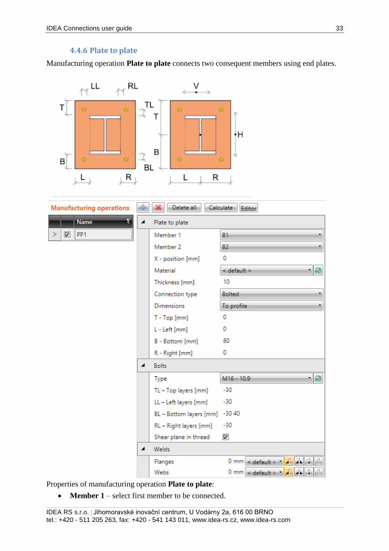
4.4.6 Plate to plate
Manufacturing operation Plate to plate connects two consequent members using end plates.
Properties of manufacturing operation Plate to plate:
Member 1 – select first member to be connected.
IDEA Connections user guide 34
IDEA RS s.r.o. | Jihomoravské inovační centrum, U Vodárny 2a, 616 00 BRNO
tel.: +420 - 511 205 263, fax: +420 - 541 143 011, www.idea-rs.cz, www.idea-rs.com
Member 2 – select second member to be connected.
X – position – input position of plate-to-plate connection from the beginning of
connected member.
Material – select material of plates. Member material is taken as default.
Thickness – input thickness of end plates.
Connection type – select the type of connection between Member 1 and Member2:
o Bolted – the connection is bolted using two end plates.
o Welded – the connection is welded, both beams are connected using one
common end plate.
Dimensions – select mode to determine the end plate dimensions:
o To profile – plate dimensions are defined by offset to top, bottom, left and
right most outer edge of cross-section.
o To profile symmetrical – plate dimensions are defined by offset to top and
left most outer edge of cross-section.
o Rectangle – plate dimensions are defined by distances of top, bottom, left and
right plate edge from the centroid of member cross-section.
o Rectangle symmetrical – plate dimensions are defined by distances of top and
left plate edge from the centroid of member cross-section.
o Circle – circular plate dimension is defined by outer radius and radius of
opening.
T – Top – input offset of top plate edge from most outer top cross-section edge or
centroid of cross-section.
L – Left – input offset of left plate edge from most outer left cross-section edge or
centroid of cross-section.
B – Bottom – input offset of bottom plate edge from most outer bottom cross-section
edge or centroid of cross-section.
R – Right – input offset of right plate edge from most outer right cross-section edge or
centroid of cross-section.
Radius – input outer radius of circular end plate.
Inner radius – input radius of opening in circular end plate.
Property group Bolts – definition of bolts in connection – see 4.4.26 Input of bolts by layers.
Properties group Welds – input of welds properties – see 4.4.25 Welds properties:
Flanges – properties of welds on flanges of connected member.
Webs – properties of welds on webs of connected member.
IDEA Connections user guide 35
IDEA RS s.r.o. | Jihomoravské inovační centrum, U Vodárny 2a, 616 00 BRNO
tel.: +420 - 511 205 263, fax: +420 - 541 143 011, www.idea-rs.cz, www.idea-rs.com
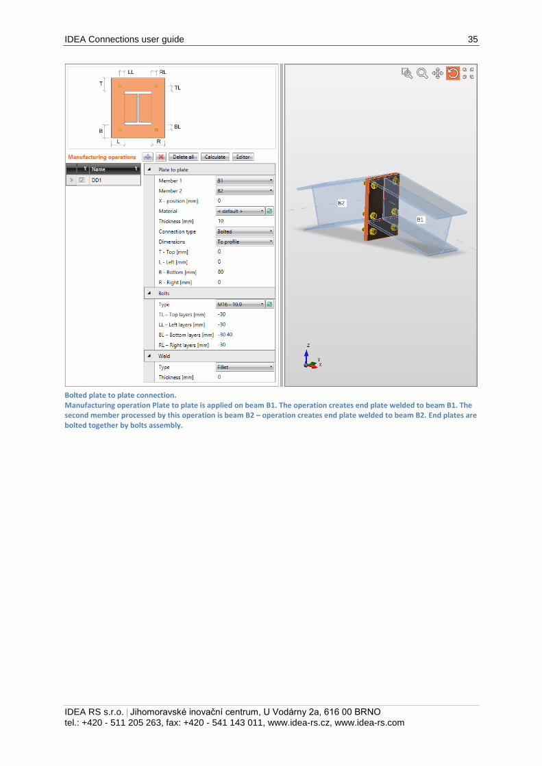
Bolted plate to plate connection. Manufacturing operation Plate to plate is applied on beam B1. The operation creates end plate welded to beam B1. The second member processed by this operation is beam B2 – operation creates end plate welded to beam B2. End plates are bolted together by bolts assembly.
IDEA Connections user guide 36
IDEA RS s.r.o. | Jihomoravské inovační centrum, U Vodárny 2a, 616 00 BRNO
tel.: +420 - 511 205 263, fax: +420 - 541 143 011, www.idea-rs.cz, www.idea-rs.com
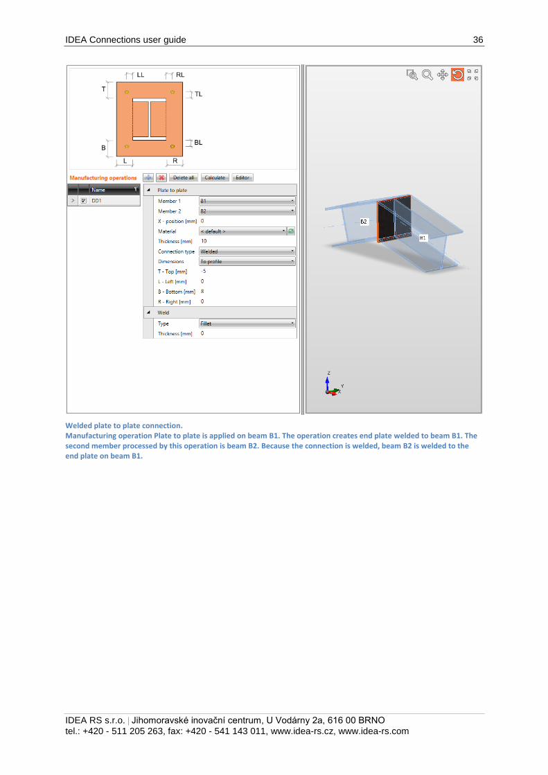
Welded plate to plate connection. Manufacturing operation Plate to plate is applied on beam B1. The operation creates end plate welded to beam B1. The second member processed by this operation is beam B2. Because the connection is welded, beam B2 is welded to the end plate on beam B1.
IDEA Connections user guide 37
IDEA RS s.r.o. | Jihomoravské inovační centrum, U Vodárny 2a, 616 00 BRNO
tel.: +420 - 511 205 263, fax: +420 - 541 143 011, www.idea-rs.cz, www.idea-rs.com
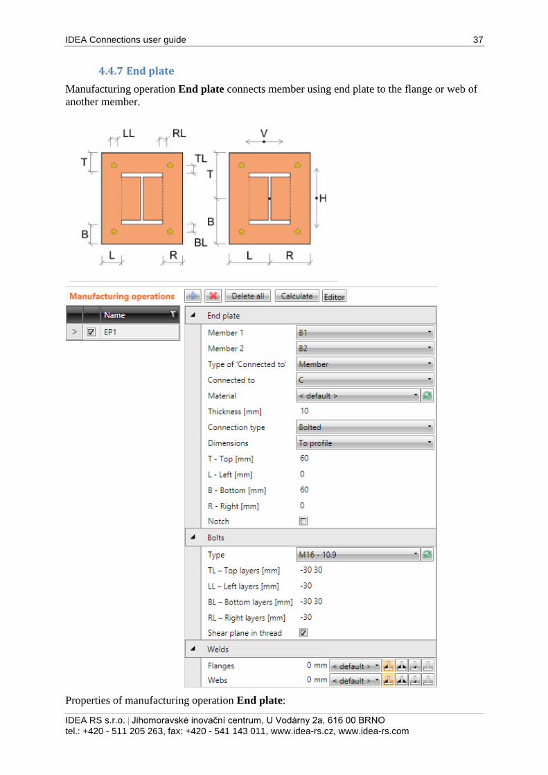
4.4.7 End plate
Manufacturing operation End plate connects member using end plate to the flange or web of
another member.
Properties of manufacturing operation End plate:
IDEA Connections user guide 38
IDEA RS s.r.o. | Jihomoravské inovační centrum, U Vodárny 2a, 616 00 BRNO
tel.: +420 - 511 205 263, fax: +420 - 541 143 011, www.idea-rs.cz, www.idea-rs.com
Member 1 – select first member to be connected by end plate to the “Connected to”
member.
Member 2 – select second member (opposite to Member 1) to be connected by end
plate to the “Connected to” member using the same bolt assembly as for Member 1.
Type of ‚Connected to‘ – select type of connection part, to which Member 1 or
Member 2 are connected using the end plate(s):
o Member – members are connected to another member.
o Plate – members are connected to plate.
Connected to – select member, to which Member 1 and Member 2 are connected by
end plate.
Material – select material of end plate. Member material is taken as default.
Thickness – input thickness of end plate.
Connection type – select the type of connection between end plate and “Connected
to” member:
o Bolted – end plate is bolted to the “Connected to” member.
o Welded – end plate is welded to the “Connected to” member.
Dimensions – select mode to determine the end plate dimensions:
o To profile – plate dimensions are defined by offset to top, bottom, left and
right most outer edge of cross-section.
o To profile symmetrical – plate dimensions are defined by offset to top and
left most outer edge of cross-section.
o Rectangle – plate dimensions are defined by distances of top, bottom, left and
right plate edge from the centroid of member cross-section.
o Rectangle symmetrical – plate dimensions are defined by distances of top and
left plate edge from the centroid of member cross-section.
o Circle – circular plate dimension is defined by outer radius and radius of
opening.
T – Top – input offset of top plate edge from most outer top cross-section edge or
centroid of cross-section.
L – Left – input offset of left plate edge from most outer left cross-section edge or
centroid of cross-section.
B – Bottom – input offset of bottom plate edge from most outer bottom cross-section
edge or centroid of cross-section.
R – Right – input offset of right plate edge from most outer right cross-section edge or
centroid of cross-section.
Radius – input outer radius of circular end plate.
Inner radius – input radius of opening in circular end plate.
Notch – switch on/off generation of flange (and web) notch in case the flanges of
connected member are aligned to flanges of “Connected to” member and the flanges
are in collision.
Notch offset – input distance between edges of plates in notched area.
Property group Bolts – see 4.4.26 Input of bolts by layers.
Properties group Welds – input of welds properties – see 4.4.25 Welds properties:
Flanges – properties of welds on flanges of connected member.
Webs – properties of welds on webs of connected member.
IDEA Connections user guide 39
IDEA RS s.r.o. | Jihomoravské inovační centrum, U Vodárny 2a, 616 00 BRNO
tel.: +420 - 511 205 263, fax: +420 - 541 143 011, www.idea-rs.cz, www.idea-rs.com
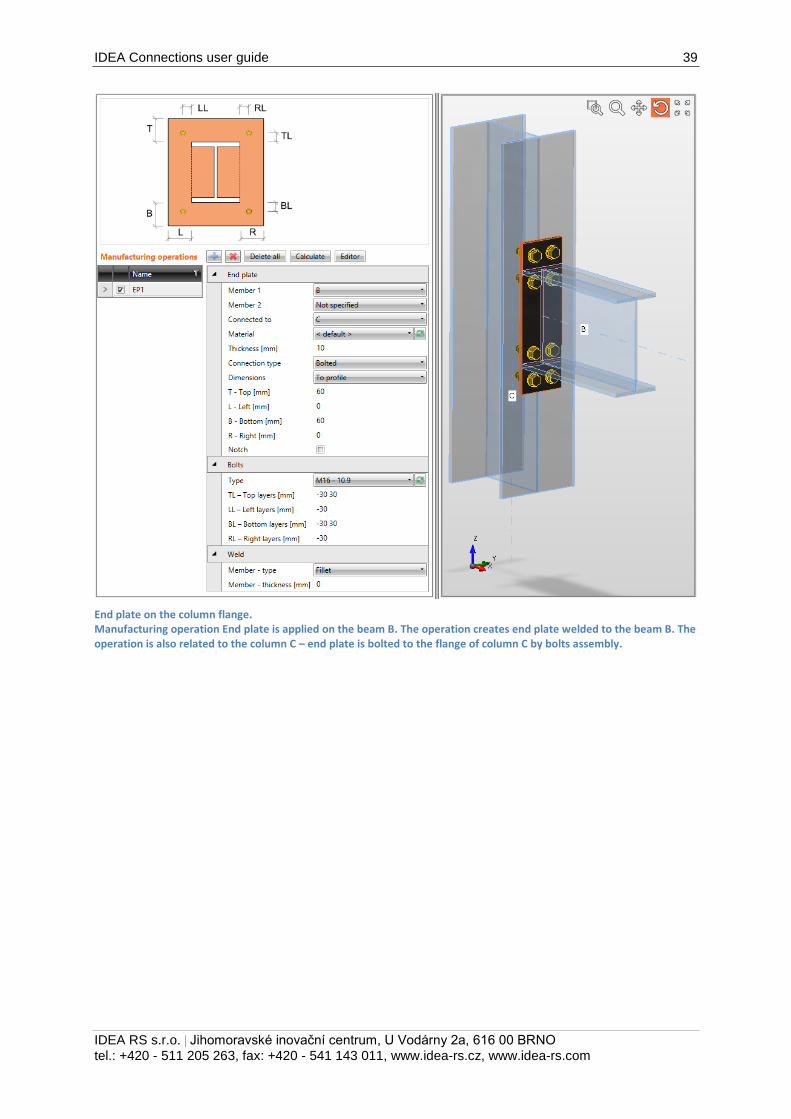
End plate on the column flange. Manufacturing operation End plate is applied on the beam B. The operation creates end plate welded to the beam B. The operation is also related to the column C – end plate is bolted to the flange of column C by bolts assembly.
IDEA Connections user guide 40
IDEA RS s.r.o. | Jihomoravské inovační centrum, U Vodárny 2a, 616 00 BRNO
tel.: +420 - 511 205 263, fax: +420 - 541 143 011, www.idea-rs.cz, www.idea-rs.com
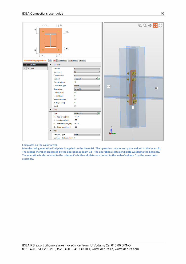
End plates on the column web. Manufacturing operation End plate is applied on the beam B1. The operation creates end plate welded to the beam B1. The second member processed by the operation is beam B2 – the operation creates end plate welded to the beam B2. The operation is also related to the column C – both end plates are bolted to the web of column C by the same bolts assembly.
IDEA Connections user guide 41
IDEA RS s.r.o. | Jihomoravské inovační centrum, U Vodárny 2a, 616 00 BRNO
tel.: +420 - 511 205 263, fax: +420 - 541 143 011, www.idea-rs.cz, www.idea-rs.com
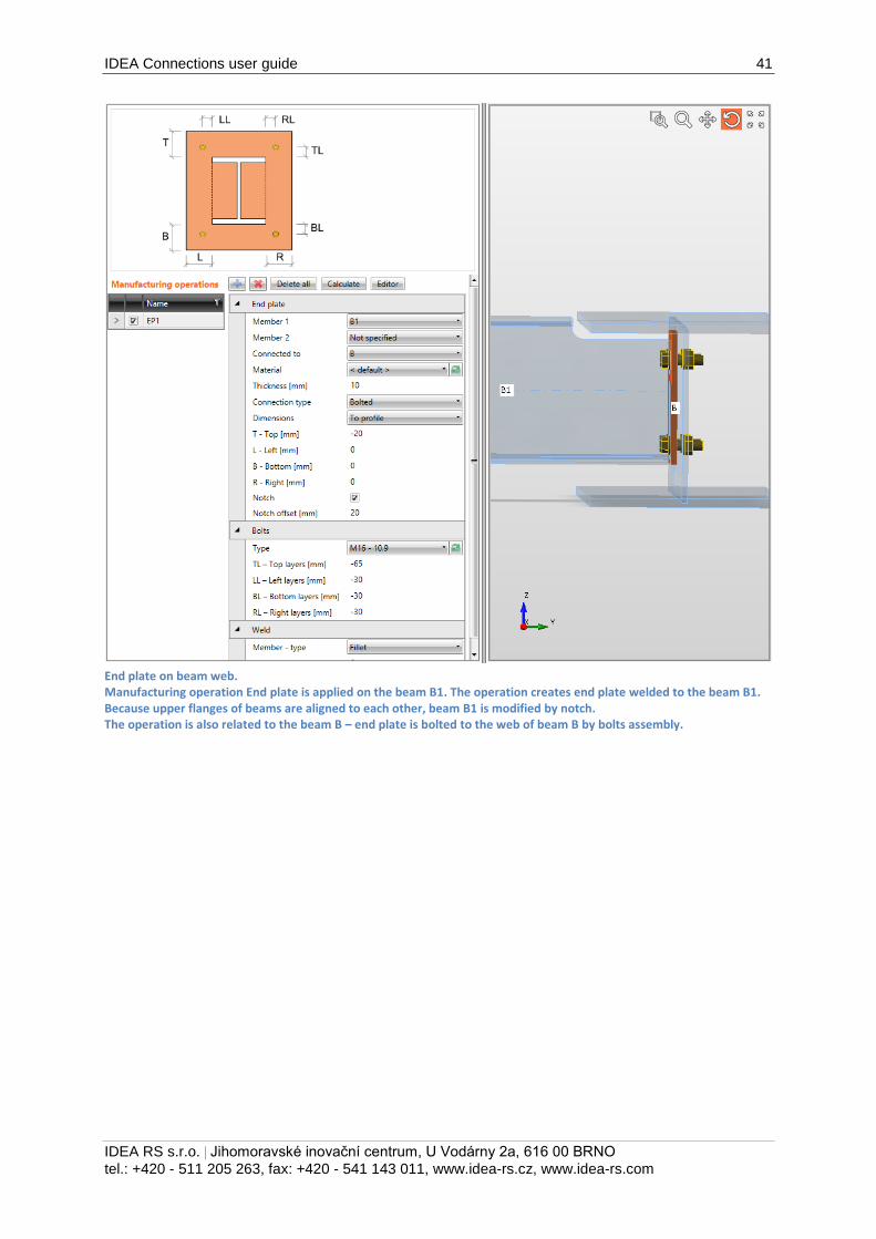
End plate on beam web. Manufacturing operation End plate is applied on the beam B1. The operation creates end plate welded to the beam B1. Because upper flanges of beams are aligned to each other, beam B1 is modified by notch. The operation is also related to the beam B – end plate is bolted to the web of beam B by bolts assembly.
IDEA Connections user guide 42
IDEA RS s.r.o. | Jihomoravské inovační centrum, U Vodárny 2a, 616 00 BRNO
tel.: +420 - 511 205 263, fax: +420 - 541 143 011, www.idea-rs.cz, www.idea-rs.com
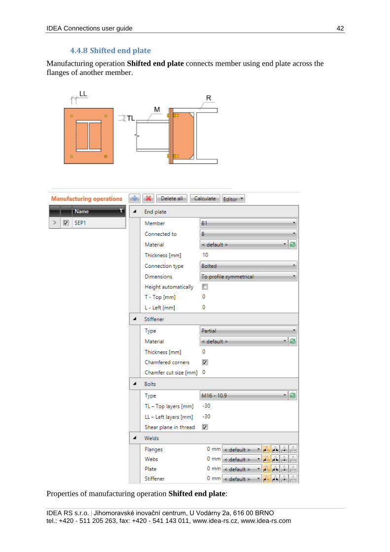
4.4.8 Shifted end plate
Manufacturing operation Shifted end plate connects member using end plate across the
flanges of another member.
Properties of manufacturing operation Shifted end plate:
IDEA Connections user guide 43
IDEA RS s.r.o. | Jihomoravské inovační centrum, U Vodárny 2a, 616 00 BRNO
tel.: +420 - 511 205 263, fax: +420 - 541 143 011, www.idea-rs.cz, www.idea-rs.com
Member – select member to be connected by shifted end plate to the “Connected to”
member.
Connected to – select member, to which the Member is connected by shifted end
plate.
Material – select material of shifted end plate. Member material is taken as default.
Thickness – input thickness of shifted end plate.
Connection type – select the connection type:
o Bolted – the connection contains two end plates – one is welded to flanges of
“Connected to” member, second is welded to the end of connected member.
Both end plates are connected by bolts assembly.
o Welded – connection contains only one end plate, which is welded both to
flanges of “Connected to” member and to the end of connected member.
Dimensions – select mode to determine the end plate dimensions:
o To profile – plate dimensions are defined by offset to top, bottom, left and
right most outer edge of cross-section.
o To profile symmetrical – plate dimensions are defined by offset to top and
left most outer edge of cross-section.
o Rectangle – plate dimensions are defined by distances of top, bottom, left and
right plate edge from the centroid of member cross-section.
o Rectangle symmetrical – plate dimensions are defined by distances of top and
left plate edge from the centroid of member cross-section.
Height automatically – if the option is selected, the height of end plates is calculated
automatically according to the height of “Connected to” member and only width of
plates can be defined. If the option is not selected, the both height and width of end
plate can be defined.
T – Top – input offset of top plate edge from most outer top cross-section edge or
centroid of cross-section.
L – Left – input offset of left plate edge from most outer left cross-section edge or
centroid of cross-section.
B – Bottom – input offset of bottom plate edge from most outer bottom cross-section
edge or centroid of cross-section.
R – Right – input offset of right plate edge from most outer right cross-section edge or
centroid of cross-section.
Properties group Stiffener – parameters of vertical stiffener under end plate:
Type – select type of stiffener:
o None – no stiffener under end plate is applied.
o Full – the height of stiffener under the end plate is equal to inner distance
between flanges of “Connected to” member.
o Partial – the height of stiffener under the end plate is equal to the height of the
end plate.
Material –select material of stiffener. Member material is taken as default.
Thickness – input thickness of stiffener.
Chamfered corners – switch on/off chamfers of stiffener corners (between flange and
web of modified member).
Chamfer cut size – input the length of cut along edges (from the corner). Value 0
means, that the length of cut is determined automatically according to the cross-
section (only for rolled sections).
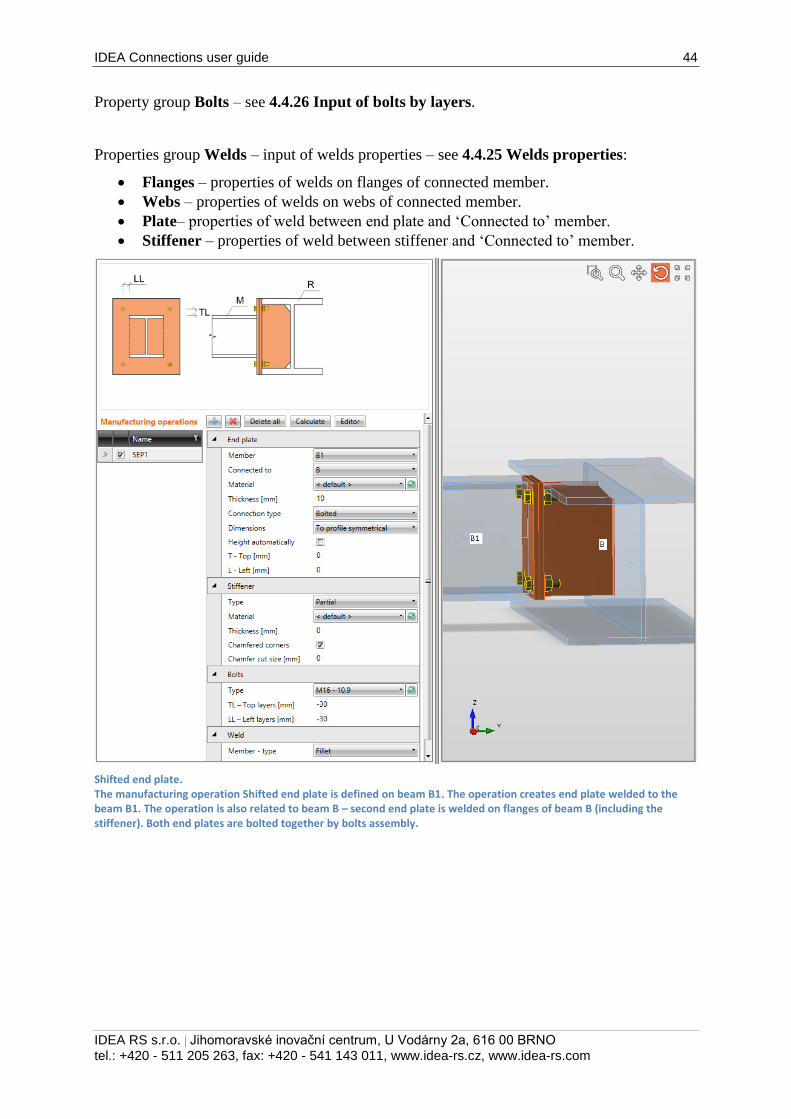
IDEA Connections user guide 44
IDEA RS s.r.o. | Jihomoravské inovační centrum, U Vodárny 2a, 616 00 BRNO
tel.: +420 - 511 205 263, fax: +420 - 541 143 011, www.idea-rs.cz, www.idea-rs.com
Property group Bolts – see 4.4.26 Input of bolts by layers.
Properties group Welds – input of welds properties – see 4.4.25 Welds properties:
Flanges – properties of welds on flanges of connected member.
Webs – properties of welds on webs of connected member.
Plate– properties of weld between end plate and ‘Connected to’ member.
Stiffener – properties of weld between stiffener and ‘Connected to’ member.
Shifted end plate. The manufacturing operation Shifted end plate is defined on beam B1. The operation creates end plate welded to the beam B1. The operation is also related to beam B – second end plate is welded on flanges of beam B (including the stiffener). Both end plates are bolted together by bolts assembly.
IDEA Connections user guide 45
IDEA RS s.r.o. | Jihomoravské inovační centrum, U Vodárny 2a, 616 00 BRNO
tel.: +420 - 511 205 263, fax: +420 - 541 143 011, www.idea-rs.cz, www.idea-rs.com
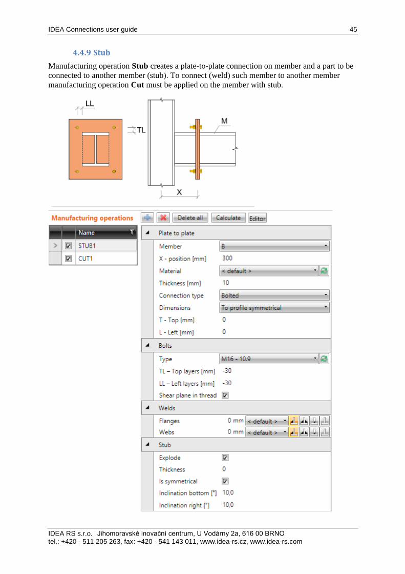
4.4.9 Stub
Manufacturing operation Stub creates a plate-to-plate connection on member and a part to be
connected to another member (stub). To connect (weld) such member to another member
manufacturing operation Cut must be applied on the member with stub.
IDEA Connections user guide 46
IDEA RS s.r.o. | Jihomoravské inovační centrum, U Vodárny 2a, 616 00 BRNO
tel.: +420 - 511 205 263, fax: +420 - 541 143 011, www.idea-rs.cz, www.idea-rs.com
Properties of manufacturing operation Stub:
Member – select member to apply the stub on.
X – position – input position of plate-to-plate connection from the beginning of
modified member.
Material – select material of plates. Member material is taken as default.
Thickness – input thickness of end plates.
Connection type – select the connection type:
o Bolted – the connection is bolted using two end plates – one end plate is
welded to the stub, second on the end of modified member. Plates are
connected by bolts assembly.
o Welded – the connection is welded. End plate is welded to the stub and to the
end of modified member.
Dimensions – select mode to determine the end plate dimensions:
o To profile – plate dimensions are defined by offset to top, bottom, left and
right most outer edge of cross-section.
o To profile symmetrical – plate dimensions are defined by offset to top and
left most outer edge of cross-section.
o Rectangle – plate dimensions are defined by distances of top, bottom, left and
right plate edge from the centroid of member cross-section.
o Rectangle symmetrical – plate dimensions are defined by distances of top and
left plate edge from the centroid of member cross-section.
o Circle – circular plate dimension is defined by outer radius and radius of
opening.
T – Top – input offset of top plate edge from most outer top cross-section edge or
centroid of cross-section.
L – Left – input offset of left plate edge from most outer left cross-section edge or
centroid of cross-section.
B – Bottom – input offset of bottom plate edge from most outer bottom cross-section
edge or centroid of cross-section.
R – Right – input offset of right plate edge from most outer right cross-section edge or
centroid of cross-section.
Radius – input outer radius of circular end plate.
Inner radius – input radius of opening in circular end plate.
Property group Bolts – see 4.4.26 Input of bolts by layers:
Properties group Welds – input of welds properties:
Welds – input of welds properties – see 4.4.25 Welds properties:
Flanges – properties of welds on flanges of connected member.
Webs – properties of welds on webs of connected member.
Properties group Stub – definition of stub:
Explode – if the option is selected, the cross-section of stub is exploded to individual
plates. If the option is not selected, the cross-section of stub is prismatic and the same

IDEA Connections user guide 47
IDEA RS s.r.o. | Jihomoravské inovační centrum, U Vodárny 2a, 616 00 BRNO
tel.: +420 - 511 205 263, fax: +420 - 541 143 011, www.idea-rs.cz, www.idea-rs.com
as the cross-section of modified member. If the stub is exploded, inclination of
individual plates can be defined.
Is symmetrical – if the option is selected, the exploded stub is considered to be
symmetrical around vertical and horizontal axis and thus two inclinations can be
defined. If the option is not selected, inclinations can be defined on all sides of stub..
Inclination bottom – input inclination of bottom plate of stub.
Inclination right – input inclination of right plate of stub.
Inclination top – input inclination of top plate of stub.
Inclination left – input inclination of left plate of stub.
Stub bolted on beam and welded on column. Manufacturing operation Stub is applied on beam B. The operation divides the beam to two parts and creates two end plates. One end plate is welded to the beam, second is welded to the stub. End plates are bolted together by bolts assembly. The stub is exploded to individual plates and the plates are inclined to create taper. Manufacturing operation Cut is applied on beam B to cut the beam B according the closer edge of column C – the stub is welded to the flange of column C.
IDEA Connections user guide 48
IDEA RS s.r.o. | Jihomoravské inovační centrum, U Vodárny 2a, 616 00 BRNO
tel.: +420 - 511 205 263, fax: +420 - 541 143 011, www.idea-rs.cz, www.idea-rs.com
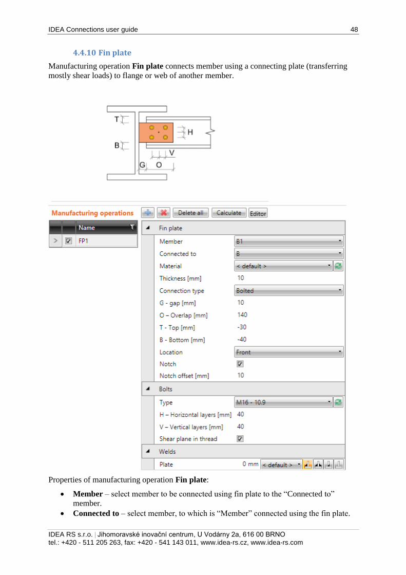
4.4.10 Fin plate
Manufacturing operation Fin plate connects member using a connecting plate (transferring
mostly shear loads) to flange or web of another member.
Properties of manufacturing operation Fin plate:
Member – select member to be connected using fin plate to the “Connected to”
member.
Connected to – select member, to which is “Member” connected using the fin plate.
IDEA Connections user guide 49
IDEA RS s.r.o. | Jihomoravské inovační centrum, U Vodárny 2a, 616 00 BRNO
tel.: +420 - 511 205 263, fax: +420 - 541 143 011, www.idea-rs.cz, www.idea-rs.com
Material – select material of fin plate. Member material is taken as default.
Thickness – input thickness of fin plate.
Connection type – select the type of connection between fin plate and “Member”:
o Bolted – selected “Member” is bolted to the fin plate.
o Welded – selected “Member” is welded to the fin plate.
G – Gap – input distance between “Member” and “Connected to” member.
O – Overlap – input overlap of fin plate and the web of “Member”, from the web
edge of “Member”.
T – Top – input offset of top edge of fin plate from the top edge of cross-section of
“Member”.
B – Bottom – input offset of bottom edge of fin plate from the bottom edge of cross-
section of “Member”.
Location – select side, on which the fin plate is applied:
o Front – fin plate is applied on one side of the web of selected member.
o Rear – fin plate is applied on the other side of the web of selected member.
Notch - switch on/off generation of flange (and web) notch in case the flanges of
connected member are aligned to flanges of “Connected to” member and the flanges
are in collision.
Notch offset – input distance between edges of plates in notched area.
Property group Bolts – definition of bolts in connection:
Type – select bolts assembly. Click to add new bolts assembly.
H – Horizontal layers – input distances of horizontal bolt layers (separated by
spaces) from the centroid of overlap of fin plate and web of selected “Member”.
V – Vertical layers – – input distances of vertical bolt layers (separated by spaces)
from the centroid of overlap of fin plate and web of selected “Member”.
Shear plane in thread – if selected, the gross area of bolt (reduced by thread) is taken
into account in the bolts check.
Properties group Welds – input of welds properties – see 4.4.25 Welds properties:
Plate – properties of weld between fin plate and ‘Connected to’ member.
Member – properties of weld between connected member and fin plate (for welded
connection).
IDEA Connections user guide 50
IDEA RS s.r.o. | Jihomoravské inovační centrum, U Vodárny 2a, 616 00 BRNO
tel.: +420 - 511 205 263, fax: +420 - 541 143 011, www.idea-rs.cz, www.idea-rs.com
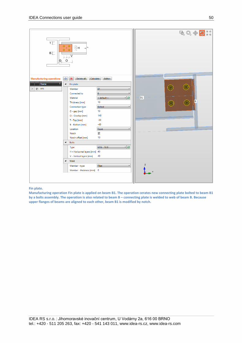
Fin plate. Manufacturing operation Fin plate is applied on beam B1. The operation cerates new connecting plate bolted to beam B1 by a bolts assembly. The operation is also related to beam B – connecting plate is welded to web of beam B. Because upper flanges of beams are aligned to each other, beam B1 is modified by notch.
IDEA Connections user guide 51
IDEA RS s.r.o. | Jihomoravské inovační centrum, U Vodárny 2a, 616 00 BRNO
tel.: +420 - 511 205 263, fax: +420 - 541 143 011, www.idea-rs.cz, www.idea-rs.com
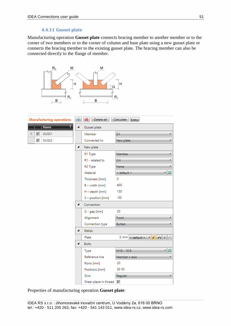
4.4.11 Gusset plate
Manufacturing operation Gusset plate connects bracing member to another member or to the
corner of two members or to the corner of column and base plate using a new gusset plate or
connects the bracing member to the existing gusset plate. The bracing member can also be
connected directly to the flange of member.
Properties of manufacturing operation Gusset plate:
IDEA Connections user guide 52
IDEA RS s.r.o. | Jihomoravské inovační centrum, U Vodárny 2a, 616 00 BRNO
tel.: +420 - 511 205 263, fax: +420 - 541 143 011, www.idea-rs.cz, www.idea-rs.com
Member – select member to be connected using the gusset plate.
Connected to – select gusset plate to connect the “Member” to the “Related to”
member:
o New plate – member is connected using newly created gusset plate.
o Existing plate – member is connected using existing plate:
Plate –select the existing gusset plate to connect the member to.
o Member plate – member is connected directly to flange (part) of another
member:
Member –.select another member to connect the member to its flange
(part).
Part of member – select part of another member to be considered as
gusset plate. The connected member is connected to the selected part.
Properties group New plate – definition of newly created gusset plate:
R1 type – select type of connection part, to which is the gusset plate related:
o Member – gusset plate is related to member.
o Plate – gusset plate is related to another plate.
R1 – related to – select the “Related to” member, to which the gusset plate is
connected.
R2 type – select type of second connection part, to which is the gusset plate also
related:
o None – gusset plate is not related to any other connection part.
o Member – gusset plate is related to another member.
o Plate – gusset plate is related to another plate.
R2 – related also to – select the second member, to which the gusset plate is also
related.
Material – select material of gusset plate. Member material is taken as default.
Thickness – input thickness of gusset plate. Value 0 means, that the thickness is
determined automatically according to the cross-section of member.
B – width – input width of gusset plate (length on “Related to” member).
H – depth – input height of gusset plate.
X - position – input shift of gusset plate along the axis of “Related to” member
(distance between plate edge centre and intersection of x-axis of connected member
and edge of “Related to ” member).
Shape – select shape of gusset plate (for gusset plate between two “Related to”
members):
o Rectangular – the gusset plate is rectangular.
o Triangular – the gusset plate is triangular.
o Chamfered – the gusset plate is rectangular with chamfered corners. The
chamfer dimensions are defined by:
D1 – input chamfer length along “Related to” member.
D2 – input chamfer length along second “Related to” member.
Properties group Connection
G – gap – input distance between edge of “Related to” member and edge of connected
member.
Alignment – select alignment of connected member to the gusset plate:
IDEA Connections user guide 53
IDEA RS s.r.o. | Jihomoravské inovační centrum, U Vodárny 2a, 616 00 BRNO
tel.: +420 - 511 205 263, fax: +420 - 541 143 011, www.idea-rs.cz, www.idea-rs.com
o Centre – axis of connected member is aligned to the centre plane of gusset
plate.
o Front – one side of connected member is aligned to the face of gusset plate.
o Rear – the other side of connected member is aligned to the face of gusset
plate.
Notched – select type of notch in gusset plate. Notch is available only if the alignment
is set to centre.
o None – notch for gusset plate is created into the connected member.
o Rectangular – a rectangular opening around edges of the connected member
is created into the gusset plate.
o Rounding A - a rectangular opening around edges of the connected member
with internal rounding of corners is created into the gusset plate.
o Rounding B - a rectangular opening around edges of the connected member
with external rounding of corners is created into the gusset plate.
Notch clearance – input extension of notch depth.
Connection type – select type of connection between gusset plate and connected
member:
o Bolted – connected member is bolted to the gusset plate.
o Welded – connected member is welded to the gusset plate.
Properties group Bolts – see 4.4.25 Welds properties
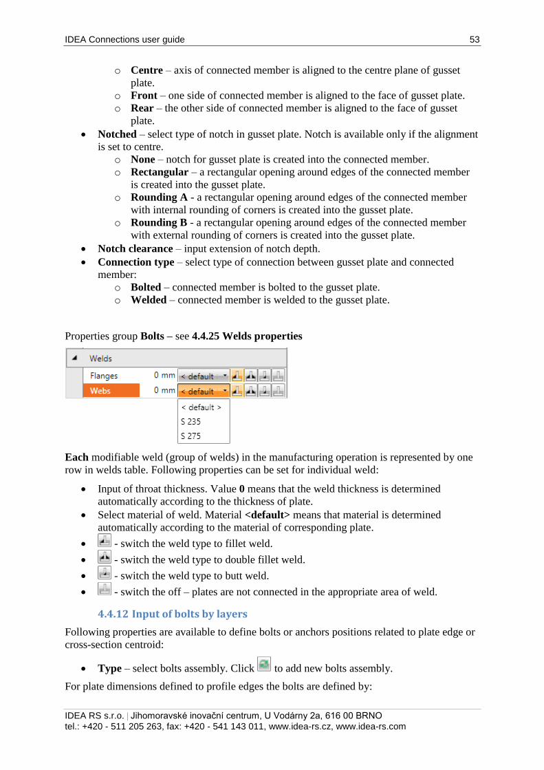
Each modifiable weld (group of welds) in the manufacturing operation is represented by one
row in welds table. Following properties can be set for individual weld:
Input of throat thickness. Value 0 means that the weld thickness is determined
automatically according to the thickness of plate.
Select material of weld. Material <default> means that material is determined
automatically according to the material of corresponding plate.
- switch the weld type to fillet weld.
- switch the weld type to double fillet weld.
- switch the weld type to butt weld.
- switch the off – plates are not connected in the appropriate area of weld.
4.4.12 Input of bolts by layers
Following properties are available to define bolts or anchors positions related to plate edge or
cross-section centroid:
Type – select bolts assembly. Click to add new bolts assembly.
For plate dimensions defined to profile edges the bolts are defined by:
IDEA Connections user guide 54
IDEA RS s.r.o. | Jihomoravské inovační centrum, U Vodárny 2a, 616 00 BRNO
tel.: +420 - 511 205 263, fax: +420 - 541 143 011, www.idea-rs.cz, www.idea-rs.com
TL – Top layers – input distances of bolt layers (separated by spaces) from the most
outer left edge of cross-section.
LL – Left layers – input distances of bolt layers (separated by spaces) from the most
outer top edge of cross-section.
BL – Bottom layers – input distances of bolt layers (separated by spaces) from the
most outer bottom edge of cross-section.
RL – Right layers – input distances of bolt layers (separated by spaces) from the most
outer right edge of cross-section.
For plate dimensions defined by rectangle the bolts are defined by:
H – Horizontal layers – input distances of horizontal bolt layers (separated by
spaces) from the centroid of plate.
V – Vertical layers – – input distances of vertical bolt layers (separated by spaces)
from the centroid of plate.
Bolts for circular plate are defined by:
Radius – input radius of bolts pitch circle.
Number – input number of bolts on the pitch circle.
Shear plane in thread – if selected, the gross area of bolt (reduced by thread) is taken
into account in the bolts check.
Input of bolt assembly.
Properties group Welds – input of welds properties – see 4.4.25 Welds properties:
Plate – properties of weld between gusset plate and ‘Related to’ member.
Member – properties of weld between connected member and fin plate (for welded
connection).
IDEA Connections user guide 55
IDEA RS s.r.o. | Jihomoravské inovační centrum, U Vodárny 2a, 616 00 BRNO
tel.: +420 - 511 205 263, fax: +420 - 541 143 011, www.idea-rs.cz, www.idea-rs.com
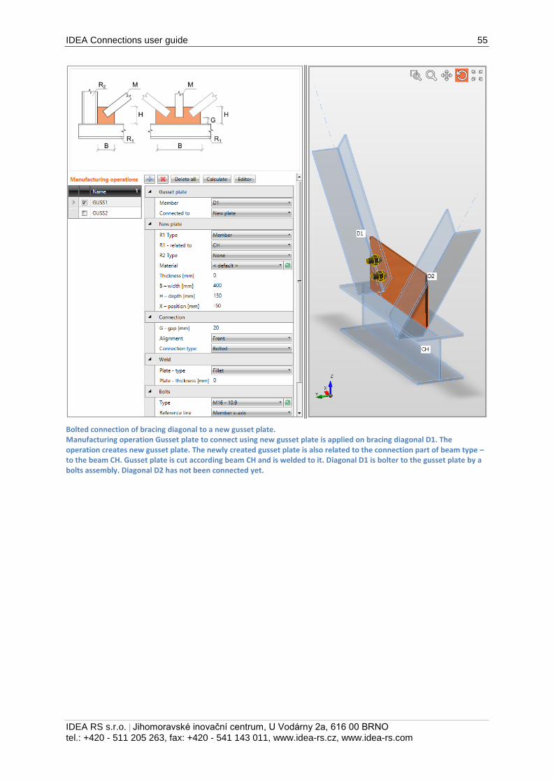
Bolted connection of bracing diagonal to a new gusset plate. Manufacturing operation Gusset plate to connect using new gusset plate is applied on bracing diagonal D1. The operation creates new gusset plate. The newly created gusset plate is also related to the connection part of beam type – to the beam CH. Gusset plate is cut according beam CH and is welded to it. Diagonal D1 is bolter to the gusset plate by a bolts assembly. Diagonal D2 has not been connected yet.
IDEA Connections user guide 56
IDEA RS s.r.o. | Jihomoravské inovační centrum, U Vodárny 2a, 616 00 BRNO
tel.: +420 - 511 205 263, fax: +420 - 541 143 011, www.idea-rs.cz, www.idea-rs.com
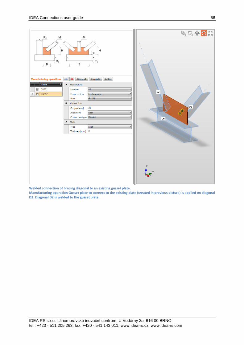
Welded connection of bracing diagonal to an existing gusset plate. Manufacturing operation Gusset plate to connect to the existing plate (created in previous picture) is applied on diagonal D2. Diagonal D2 is welded to the gusset plate.
IDEA Connections user guide 57
IDEA RS s.r.o. | Jihomoravské inovační centrum, U Vodárny 2a, 616 00 BRNO
tel.: +420 - 511 205 263, fax: +420 - 541 143 011, www.idea-rs.cz, www.idea-rs.com
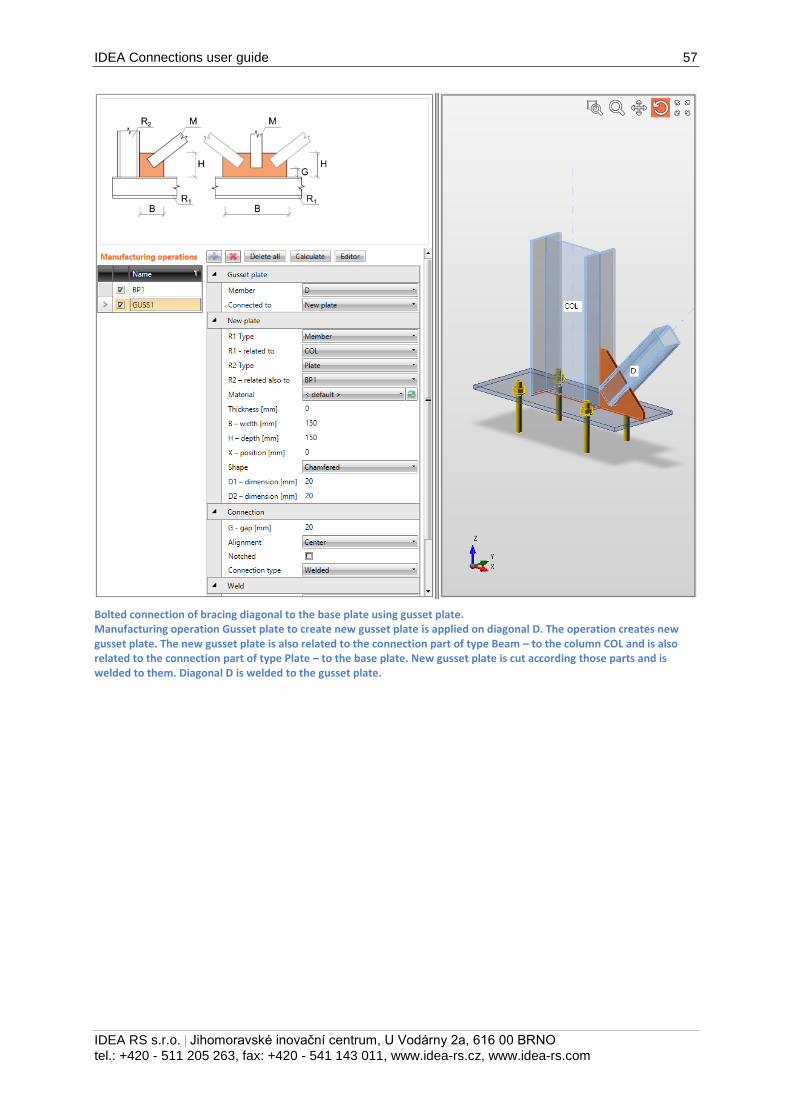
Bolted connection of bracing diagonal to the base plate using gusset plate. Manufacturing operation Gusset plate to create new gusset plate is applied on diagonal D. The operation creates new gusset plate. The new gusset plate is also related to the connection part of type Beam – to the column COL and is also related to the connection part of type Plate – to the base plate. New gusset plate is cut according those parts and is welded to them. Diagonal D is welded to the gusset plate.
IDEA Connections user guide 58
IDEA RS s.r.o. | Jihomoravské inovační centrum, U Vodárny 2a, 616 00 BRNO
tel.: +420 - 511 205 263, fax: +420 - 541 143 011, www.idea-rs.cz, www.idea-rs.com
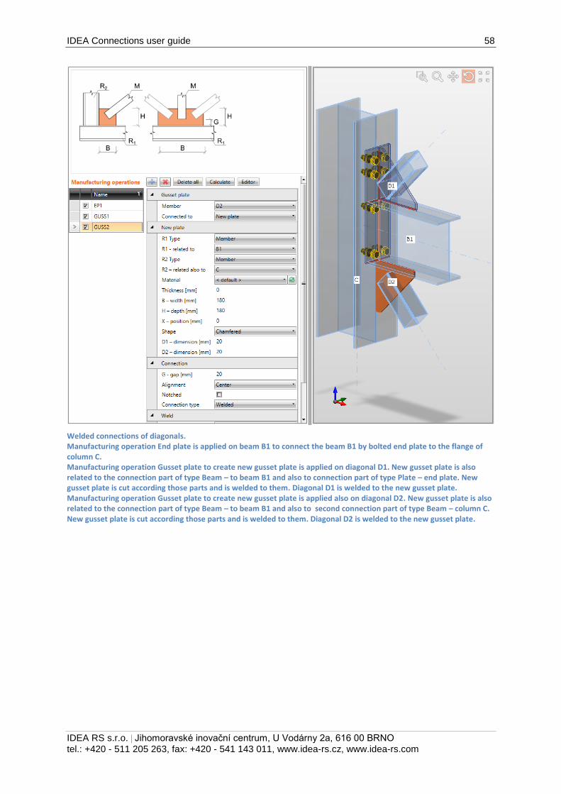
Welded connections of diagonals. Manufacturing operation End plate is applied on beam B1 to connect the beam B1 by bolted end plate to the flange of column C. Manufacturing operation Gusset plate to create new gusset plate is applied on diagonal D1. New gusset plate is also related to the connection part of type Beam – to beam B1 and also to connection part of type Plate – end plate. New gusset plate is cut according those parts and is welded to them. Diagonal D1 is welded to the new gusset plate. Manufacturing operation Gusset plate to create new gusset plate is applied also on diagonal D2. New gusset plate is also related to the connection part of type Beam – to beam B1 and also to second connection part of type Beam – column C. New gusset plate is cut according those parts and is welded to them. Diagonal D2 is welded to the new gusset plate.
IDEA Connections user guide 59
IDEA RS s.r.o. | Jihomoravské inovační centrum, U Vodárny 2a, 616 00 BRNO
tel.: +420 - 511 205 263, fax: +420 - 541 143 011, www.idea-rs.cz, www.idea-rs.com
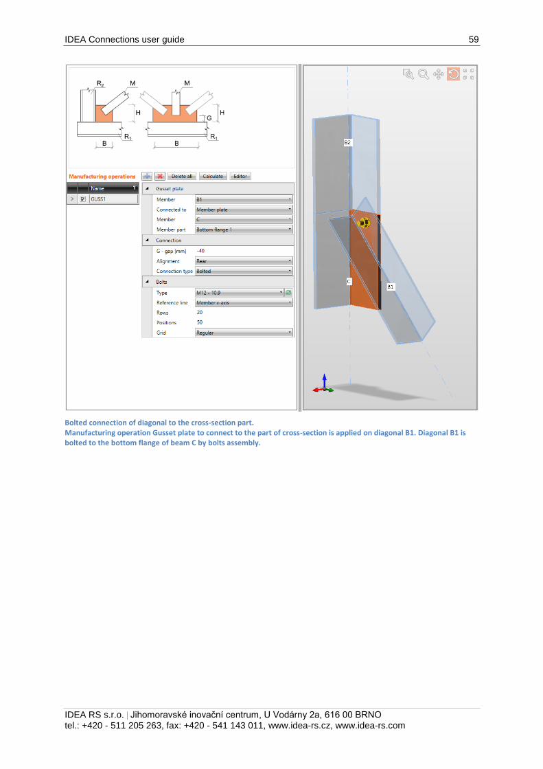
Bolted connection of diagonal to the cross-section part. Manufacturing operation Gusset plate to connect to the part of cross-section is applied on diagonal B1. Diagonal B1 is bolted to the bottom flange of beam C by bolts assembly.
IDEA Connections user guide 60
IDEA RS s.r.o. | Jihomoravské inovační centrum, U Vodárny 2a, 616 00 BRNO
tel.: +420 - 511 205 263, fax: +420 - 541 143 011, www.idea-rs.cz, www.idea-rs.com
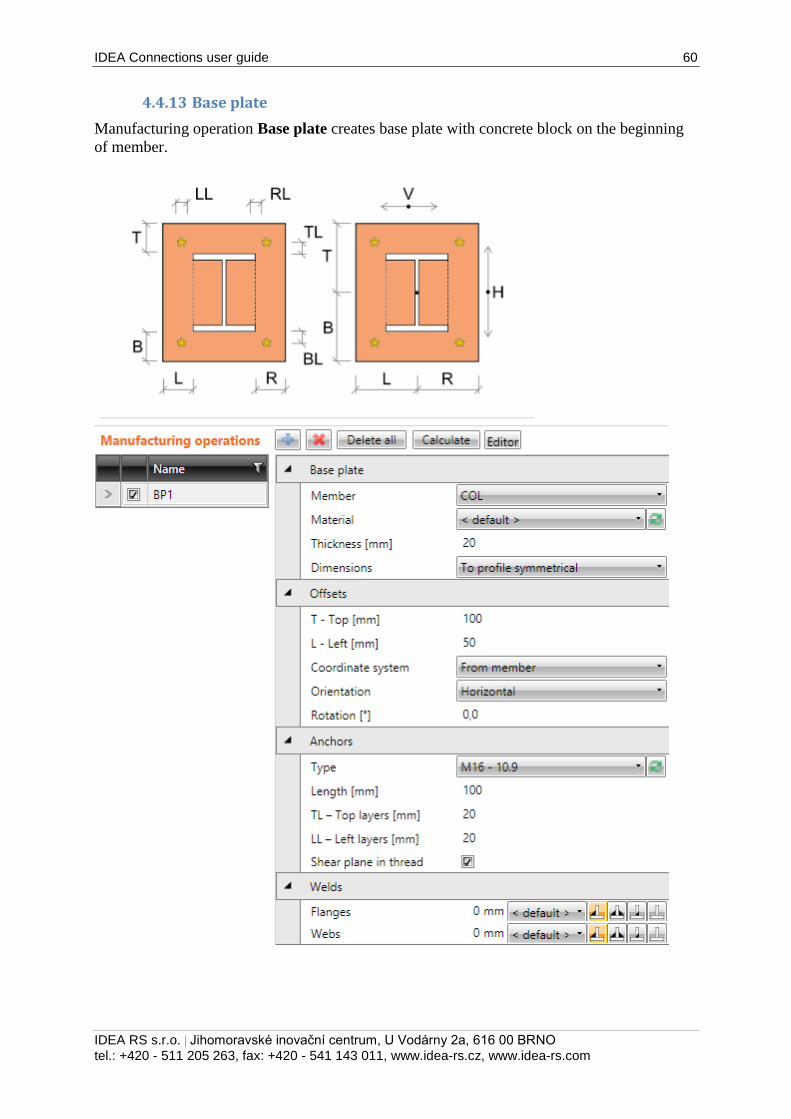
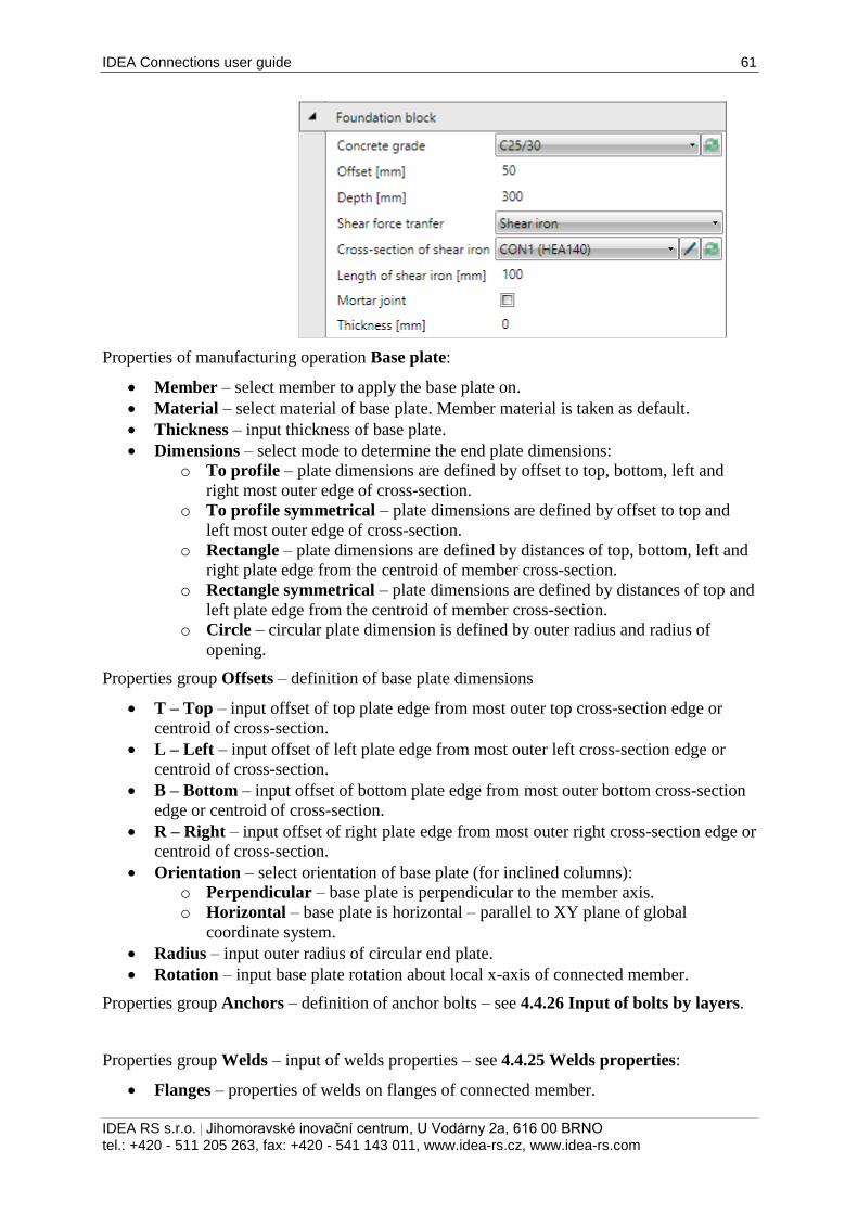
4.4.13 Base plate
Manufacturing operation Base plate creates base plate with concrete block on the beginning
of member.
IDEA Connections user guide 61
IDEA RS s.r.o. | Jihomoravské inovační centrum, U Vodárny 2a, 616 00 BRNO
tel.: +420 - 511 205 263, fax: +420 - 541 143 011, www.idea-rs.cz, www.idea-rs.com
Properties of manufacturing operation Base plate:
Member – select member to apply the base plate on.
Material – select material of base plate. Member material is taken as default.
Thickness – input thickness of base plate.
Dimensions – select mode to determine the end plate dimensions:
o To profile – plate dimensions are defined by offset to top, bottom, left and
right most outer edge of cross-section.
o To profile symmetrical – plate dimensions are defined by offset to top and
left most outer edge of cross-section.
o Rectangle – plate dimensions are defined by distances of top, bottom, left and
right plate edge from the centroid of member cross-section.
o Rectangle symmetrical – plate dimensions are defined by distances of top and
left plate edge from the centroid of member cross-section.
o Circle – circular plate dimension is defined by outer radius and radius of
opening.
Properties group Offsets – definition of base plate dimensions
T – Top – input offset of top plate edge from most outer top cross-section edge or
centroid of cross-section.
L – Left – input offset of left plate edge from most outer left cross-section edge or
centroid of cross-section.
B – Bottom – input offset of bottom plate edge from most outer bottom cross-section
edge or centroid of cross-section.
R – Right – input offset of right plate edge from most outer right cross-section edge or
centroid of cross-section.
Orientation – select orientation of base plate (for inclined columns):
o Perpendicular – base plate is perpendicular to the member axis.
o Horizontal – base plate is horizontal – parallel to XY plane of global
coordinate system.
Radius – input outer radius of circular end plate.
Rotation – input base plate rotation about local x-axis of connected member.
Properties group Anchors – definition of anchor bolts – see 4.4.26 Input of bolts by layers.
Properties group Welds – input of welds properties – see 4.4.25 Welds properties:
Flanges – properties of welds on flanges of connected member.
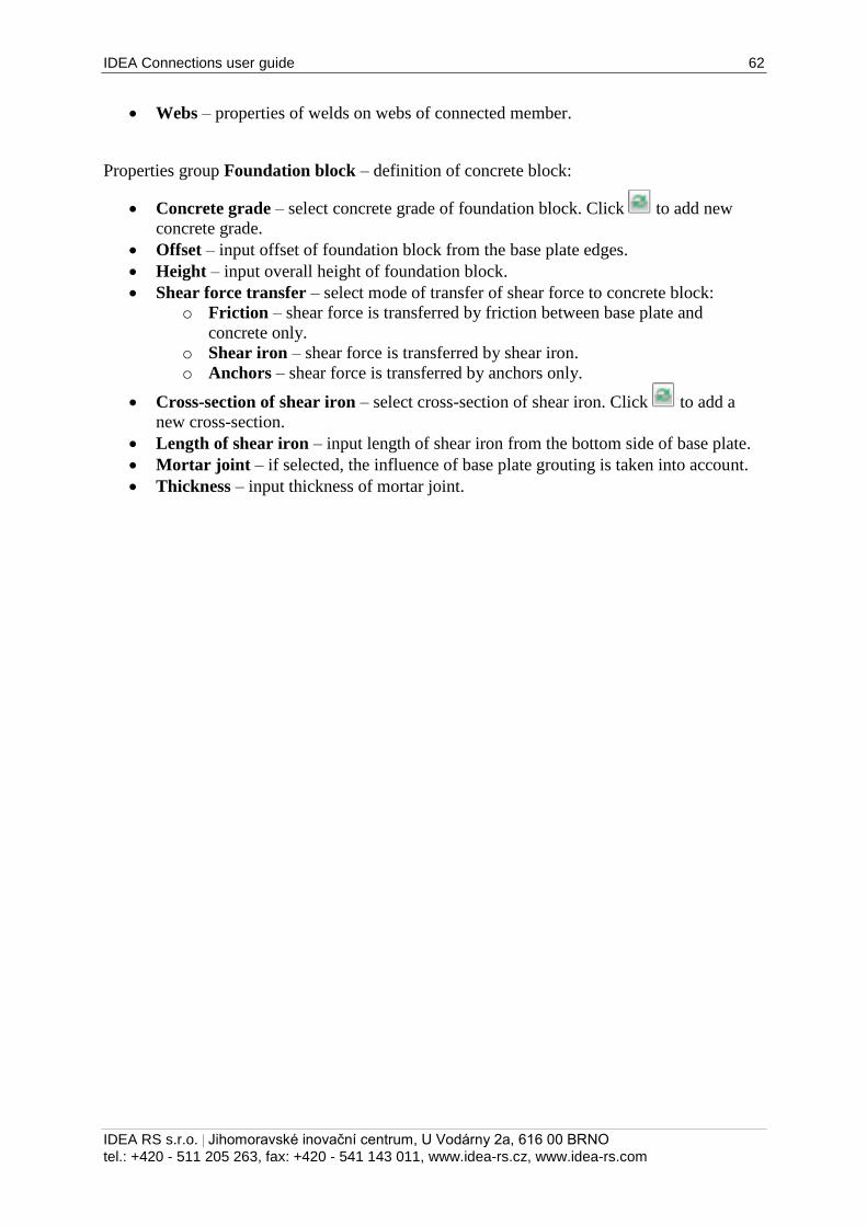
IDEA Connections user guide 62
IDEA RS s.r.o. | Jihomoravské inovační centrum, U Vodárny 2a, 616 00 BRNO
tel.: +420 - 511 205 263, fax: +420 - 541 143 011, www.idea-rs.cz, www.idea-rs.com
Webs – properties of welds on webs of connected member.
Properties group Foundation block – definition of concrete block:
Concrete grade – select concrete grade of foundation block. Click to add new
concrete grade.
Offset – input offset of foundation block from the base plate edges.
Height – input overall height of foundation block.
Shear force transfer – select mode of transfer of shear force to concrete block:
o Friction – shear force is transferred by friction between base plate and
concrete only.
o Shear iron – shear force is transferred by shear iron.
o Anchors – shear force is transferred by anchors only.
Cross-section of shear iron – select cross-section of shear iron. Click to add a
new cross-section.
Length of shear iron – input length of shear iron from the bottom side of base plate.
Mortar joint – if selected, the influence of base plate grouting is taken into account.
Thickness – input thickness of mortar joint.
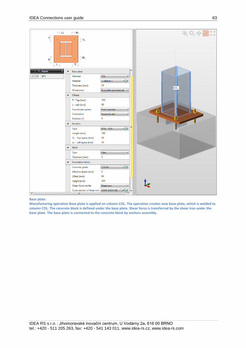
IDEA Connections user guide 63
IDEA RS s.r.o. | Jihomoravské inovační centrum, U Vodárny 2a, 616 00 BRNO
tel.: +420 - 511 205 263, fax: +420 - 541 143 011, www.idea-rs.cz, www.idea-rs.com
Base plate. Manufacturing operation Base plate is applied on column COL. The operation creates new base plate, which is welded to column COL. The concrete block is defined under the base plate. Shear force is transferred by the shear iron under the base plate. The base plate is connected to the concrete block by anchors assembly.
IDEA Connections user guide 64
IDEA RS s.r.o. | Jihomoravské inovační centrum, U Vodárny 2a, 616 00 BRNO
tel.: +420 - 511 205 263, fax: +420 - 541 143 011, www.idea-rs.cz, www.idea-rs.com
4.4.14 Splice
Manufacturing operation Splice adds a new splice on member or connects member to existing
splice. Splices can be welded or bolted. Two members can be connected by splice.
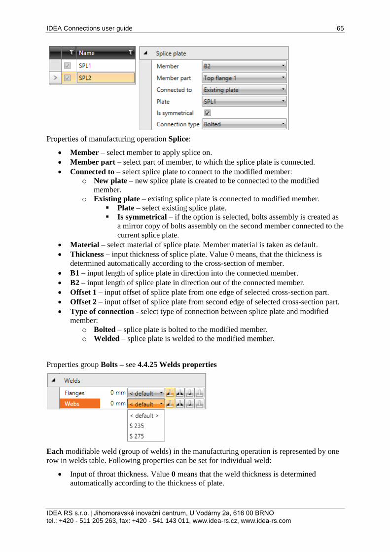
IDEA Connections user guide 65
IDEA RS s.r.o. | Jihomoravské inovační centrum, U Vodárny 2a, 616 00 BRNO
tel.: +420 - 511 205 263, fax: +420 - 541 143 011, www.idea-rs.cz, www.idea-rs.com
Properties of manufacturing operation Splice:
Member – select member to apply splice on.
Member part – select part of member, to which the splice plate is connected.
Connected to – select splice plate to connect to the modified member:
o New plate – new splice plate is created to be connected to the modified
member.
o Existing plate – existing splice plate is connected to modified member.
Plate – select existing splice plate.
Is symmetrical – if the option is selected, bolts assembly is created as
a mirror copy of bolts assembly on the second member connected to the
current splice plate.
Material – select material of splice plate. Member material is taken as default.
Thickness – input thickness of splice plate. Value 0 means, that the thickness is
determined automatically according to the cross-section of member.
B1 – input length of splice plate in direction into the connected member.
B2 – input length of splice plate in direction out of the connected member.
Offset 1 – input offset of splice plate from one edge of selected cross-section part.
Offset 2 – input offset of splice plate from second edge of selected cross-section part.
Type of connection - select type of connection between splice plate and modified
member:
o Bolted – splice plate is bolted to the modified member.
o Welded – splice plate is welded to the modified member.
Properties group Bolts – see 4.4.25 Welds properties
Each modifiable weld (group of welds) in the manufacturing operation is represented by one
row in welds table. Following properties can be set for individual weld:
Input of throat thickness. Value 0 means that the weld thickness is determined
automatically according to the thickness of plate.
IDEA Connections user guide 66
IDEA RS s.r.o. | Jihomoravské inovační centrum, U Vodárny 2a, 616 00 BRNO
tel.: +420 - 511 205 263, fax: +420 - 541 143 011, www.idea-rs.cz, www.idea-rs.com
Select material of weld. Material <default> means that material is determined
automatically according to the material of corresponding plate.
- switch the weld type to fillet weld.
- switch the weld type to double fillet weld.
- switch the weld type to butt weld.
- switch the off – plates are not connected in the appropriate area of weld.
4.4.15 Input of bolts by layers
Following properties are available to define bolts or anchors positions related to plate edge or
cross-section centroid:
Type – select bolts assembly. Click to add new bolts assembly.
For plate dimensions defined to profile edges the bolts are defined by:
TL – Top layers – input distances of bolt layers (separated by spaces) from the most
outer left edge of cross-section.
LL – Left layers – input distances of bolt layers (separated by spaces) from the most
outer top edge of cross-section.
BL – Bottom layers – input distances of bolt layers (separated by spaces) from the
most outer bottom edge of cross-section.
RL – Right layers – input distances of bolt layers (separated by spaces) from the most
outer right edge of cross-section.
For plate dimensions defined by rectangle the bolts are defined by:
H – Horizontal layers – input distances of horizontal bolt layers (separated by
spaces) from the centroid of plate.
V – Vertical layers – – input distances of vertical bolt layers (separated by spaces)
from the centroid of plate.
Bolts for circular plate are defined by:
Radius – input radius of bolts pitch circle.
Number – input number of bolts on the pitch circle.
Shear plane in thread – if selected, the gross area of bolt (reduced by thread) is taken
into account in the bolts check.
Input of bolt assembly.
Properties group Welds – input of welds properties – see 4.4.25 Welds properties:
Longitudinal – properties of welds in direction of x-axis of member.
Transversal – properties of welds in direction perpendicular to x-axis of member.
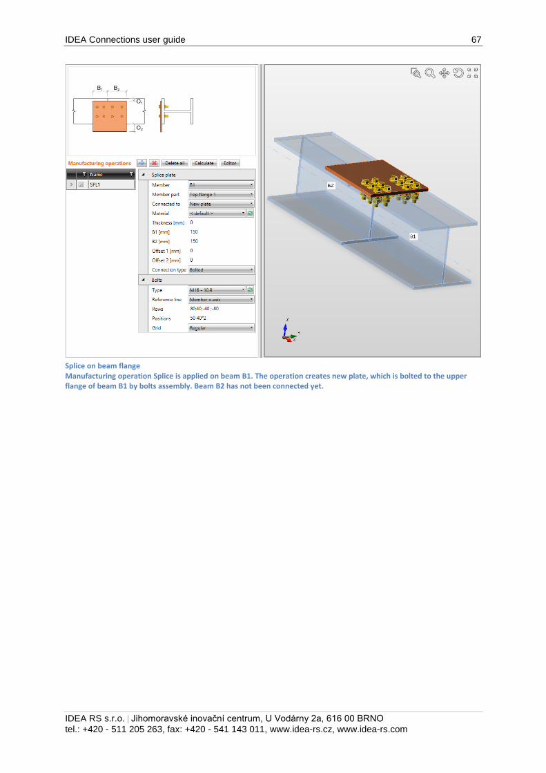
IDEA Connections user guide 67
IDEA RS s.r.o. | Jihomoravské inovační centrum, U Vodárny 2a, 616 00 BRNO
tel.: +420 - 511 205 263, fax: +420 - 541 143 011, www.idea-rs.cz, www.idea-rs.com
Splice on beam flange Manufacturing operation Splice is applied on beam B1. The operation creates new plate, which is bolted to the upper flange of beam B1 by bolts assembly. Beam B2 has not been connected yet.
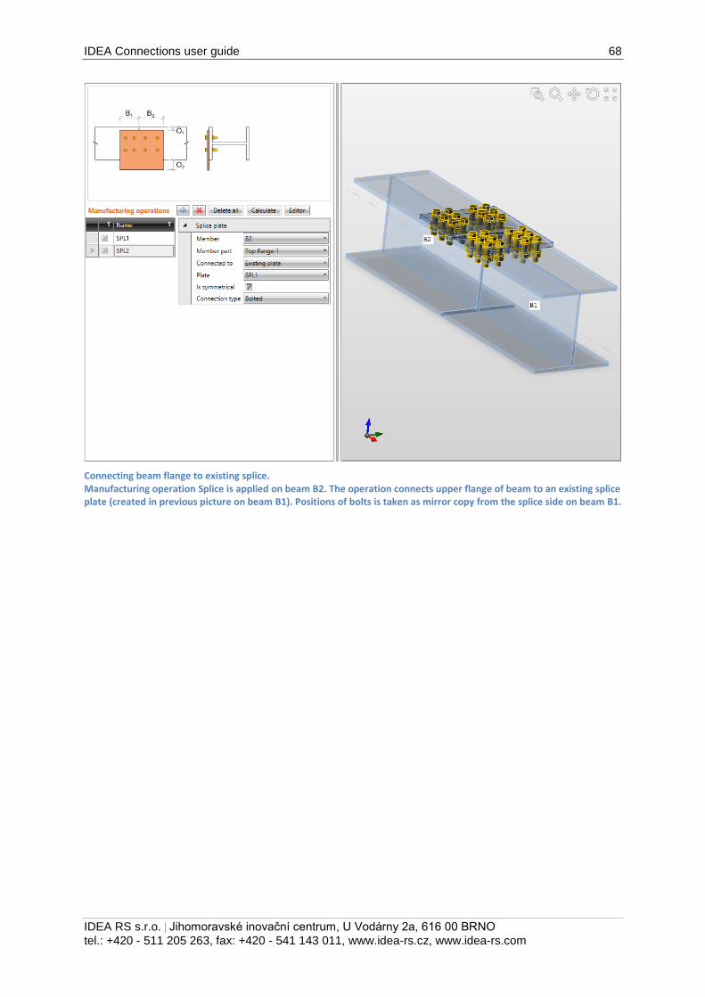
IDEA Connections user guide 68
IDEA RS s.r.o. | Jihomoravské inovační centrum, U Vodárny 2a, 616 00 BRNO
tel.: +420 - 511 205 263, fax: +420 - 541 143 011, www.idea-rs.cz, www.idea-rs.com
Connecting beam flange to existing splice. Manufacturing operation Splice is applied on beam B2. The operation connects upper flange of beam to an existing splice plate (created in previous picture on beam B1). Positions of bolts is taken as mirror copy from the splice side on beam B1.
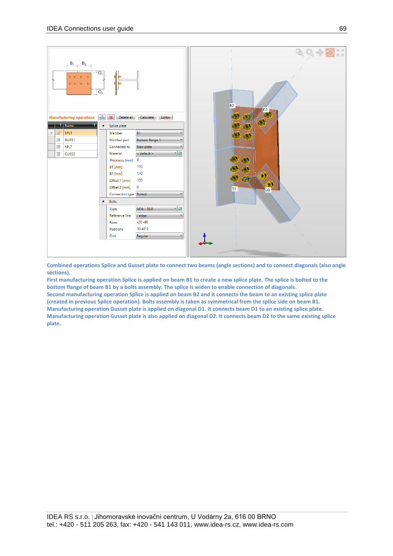
IDEA Connections user guide 69
IDEA RS s.r.o. | Jihomoravské inovační centrum, U Vodárny 2a, 616 00 BRNO
tel.: +420 - 511 205 263, fax: +420 - 541 143 011, www.idea-rs.cz, www.idea-rs.com
Combined operations Splice and Gusset plate to connect two beams (angle sections) and to connect diagonals (also angle sections). First manufacturing operation Splice is applied on beam B1 to create a new splice plate. The splice is bolted to the bottom flange of beam B1 by a bolts assembly. The splice is widen to enable connection of diagonals. Second manufacturing operation Splice is applied on beam B2 and it connects the beam to an existing splice plate (created in previous Splice operation). Bolts assembly is taken as symmetrical from the splice side on beam B1. Manufacturing operation Gusset plate is applied on diagonal D1. It connects beam D1 to an existing splice plate. Manufacturing operation Gusset plate is also applied on diagonal D2. It connects beam D2 to the same existing splice plate.
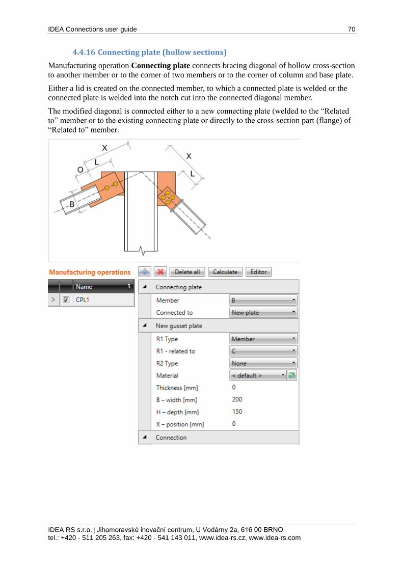
IDEA Connections user guide 70
IDEA RS s.r.o. | Jihomoravské inovační centrum, U Vodárny 2a, 616 00 BRNO
tel.: +420 - 511 205 263, fax: +420 - 541 143 011, www.idea-rs.cz, www.idea-rs.com
4.4.16 Connecting plate (hollow sections)
Manufacturing operation Connecting plate connects bracing diagonal of hollow cross-section
to another member or to the corner of two members or to the corner of column and base plate.
Either a lid is created on the connected member, to which a connected plate is welded or the
connected plate is welded into the notch cut into the connected diagonal member.
The modified diagonal is connected either to a new connecting plate (welded to the “Related
to” member or to the existing connecting plate or directly to the cross-section part (flange) of
“Related to” member.
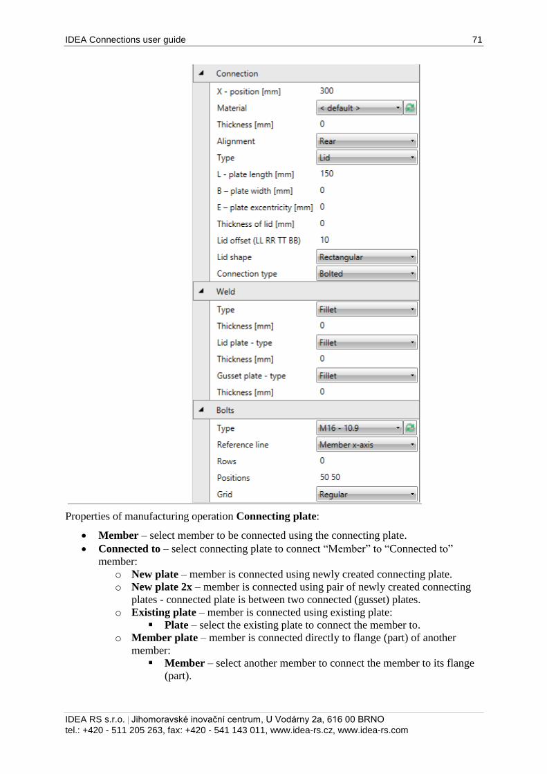
IDEA Connections user guide 71
IDEA RS s.r.o. | Jihomoravské inovační centrum, U Vodárny 2a, 616 00 BRNO
tel.: +420 - 511 205 263, fax: +420 - 541 143 011, www.idea-rs.cz, www.idea-rs.com
Properties of manufacturing operation Connecting plate:
Member – select member to be connected using the connecting plate.
Connected to – select connecting plate to connect “Member” to “Connected to”
member:
o New plate – member is connected using newly created connecting plate.
o New plate 2x – member is connected using pair of newly created connecting
plates - connected plate is between two connected (gusset) plates.
o Existing plate – member is connected using existing plate:
Plate – select the existing plate to connect the member to.
o Member plate – member is connected directly to flange (part) of another
member:
Member – select another member to connect the member to its flange
(part).
IDEA Connections user guide 72
IDEA RS s.r.o. | Jihomoravské inovační centrum, U Vodárny 2a, 616 00 BRNO
tel.: +420 - 511 205 263, fax: +420 - 541 143 011, www.idea-rs.cz, www.idea-rs.com
Part of member – select part of another member to be considered as
connecting plate. The connected member is connected to the selected
part.
Properties group New plate – definition of newly created connecting plate, welded to
“Related to” member:
R1 type – select type of connection part, to which is the connecting plate related:
o Member – connecting plate is related to member.
o Plate – connecting plate is related to another plate.
R1 – related to – select member, to which the connecting plate is connected.
R2 type – select type of second connection part, to which is the connecting plate also
related:
o None – connecting plate is not related to any other connection part.
o Member – connecting plate is related to another member.
o Plate – connecting plate is related to another plate.
R2 – related also to – select the second member, to which the connecting plate is also
related.
Material – select material of connecting plate. Member material is taken as default.
Thickness – input thickness of connecting plate. Value 0 means, that the thickness is
determined automatically according to the cross-section of member.
B – width – input width of connecting plate (length on “Related to” member).
H – depth – input height of connecting plate.
X - position – input shift of gusset plate along the axis of “Related to” member
(distance between plate edge centre and intersection of x-axis of connected member
and edge of “Related to ” member).
Shape – select shape of connecting plate (for connecting plate between two “Related
to” members):
o Rectangular – the connecting plate is rectangular.
o Triangular – the connecting plate is triangular.
o Chamfered – the connecting plate is rectangular with chamfered corners. The
chamfer dimensions are defined by:
D1 – input chamfer length along “Related to” member.
D2 – input chamfer length along second “Related to” member.
Properties group Connection:
X – position – distance between axis of “Related to” member and edge of “Member”
or edge of lid (in the axis of “Member”).
Material – select material of connecting plate.
Thickness – input thickness of connecting plate. Value 0 means, that the thickness is
determined automatically according to the cross-section of member.
Alignment – select alignment of connected plate to connecting plate:
o Front – connected plate is aligned to one side of connecting plate.
o Rear – connected plate is aligned to the other side of connecting plate.
Type – select type of connection between connected member and connecting plate:
o Lid – end of connected member is closed by a lid, the connected plate is
welded to the lid.
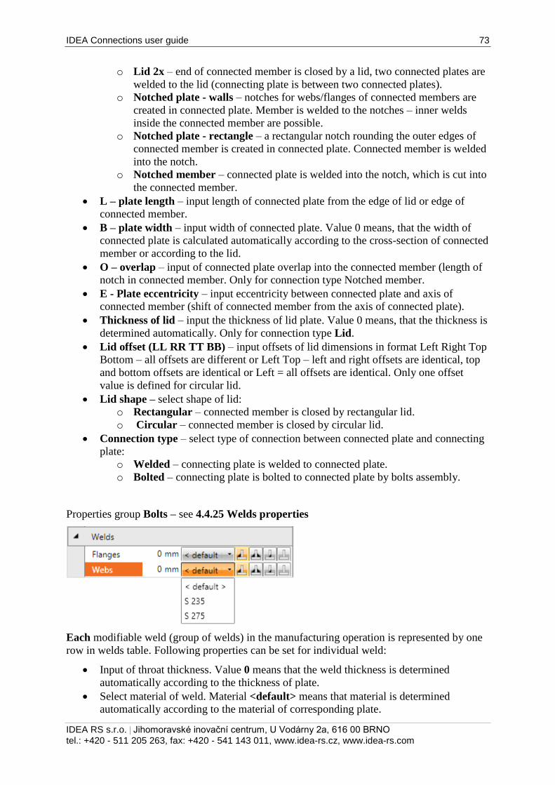
IDEA Connections user guide 73
IDEA RS s.r.o. | Jihomoravské inovační centrum, U Vodárny 2a, 616 00 BRNO
tel.: +420 - 511 205 263, fax: +420 - 541 143 011, www.idea-rs.cz, www.idea-rs.com
o Lid 2x – end of connected member is closed by a lid, two connected plates are
welded to the lid (connecting plate is between two connected plates).
o Notched plate - walls – notches for webs/flanges of connected members are
created in connected plate. Member is welded to the notches – inner welds
inside the connected member are possible.
o Notched plate - rectangle – a rectangular notch rounding the outer edges of
connected member is created in connected plate. Connected member is welded
into the notch.
o Notched member – connected plate is welded into the notch, which is cut into
the connected member.
L – plate length – input length of connected plate from the edge of lid or edge of
connected member.
B – plate width – input width of connected plate. Value 0 means, that the width of
connected plate is calculated automatically according to the cross-section of connected
member or according to the lid.
O – overlap – input of connected plate overlap into the connected member (length of
notch in connected member. Only for connection type Notched member.
E - Plate eccentricity – input eccentricity between connected plate and axis of
connected member (shift of connected member from the axis of connected plate).
Thickness of lid – input the thickness of lid plate. Value 0 means, that the thickness is
determined automatically. Only for connection type Lid.
Lid offset (LL RR TT BB) – input offsets of lid dimensions in format Left Right Top
Bottom – all offsets are different or Left Top – left and right offsets are identical, top
and bottom offsets are identical or Left = all offsets are identical. Only one offset
value is defined for circular lid.
Lid shape – select shape of lid:
o Rectangular – connected member is closed by rectangular lid.
o Circular – connected member is closed by circular lid.
Connection type – select type of connection between connected plate and connecting
plate:
o Welded – connecting plate is welded to connected plate.
o Bolted – connecting plate is bolted to connected plate by bolts assembly.
Properties group Bolts – see 4.4.25 Welds properties
Each modifiable weld (group of welds) in the manufacturing operation is represented by one
row in welds table. Following properties can be set for individual weld:
Input of throat thickness. Value 0 means that the weld thickness is determined
automatically according to the thickness of plate.
Select material of weld. Material <default> means that material is determined
automatically according to the material of corresponding plate.
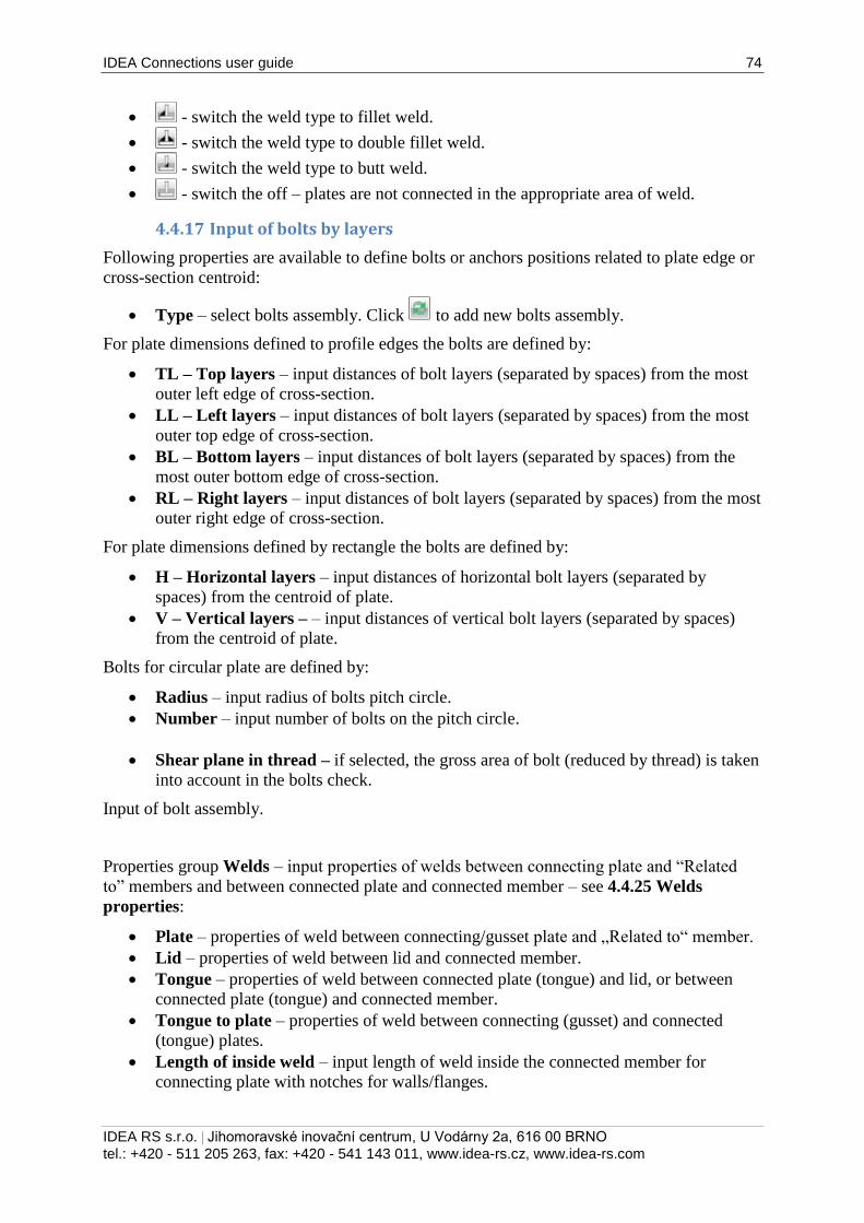
IDEA Connections user guide 74
IDEA RS s.r.o. | Jihomoravské inovační centrum, U Vodárny 2a, 616 00 BRNO
tel.: +420 - 511 205 263, fax: +420 - 541 143 011, www.idea-rs.cz, www.idea-rs.com
- switch the weld type to fillet weld.
- switch the weld type to double fillet weld.
- switch the weld type to butt weld.
- switch the off – plates are not connected in the appropriate area of weld.
4.4.17 Input of bolts by layers
Following properties are available to define bolts or anchors positions related to plate edge or
cross-section centroid:
Type – select bolts assembly. Click to add new bolts assembly.
For plate dimensions defined to profile edges the bolts are defined by:
TL – Top layers – input distances of bolt layers (separated by spaces) from the most
outer left edge of cross-section.
LL – Left layers – input distances of bolt layers (separated by spaces) from the most
outer top edge of cross-section.
BL – Bottom layers – input distances of bolt layers (separated by spaces) from the
most outer bottom edge of cross-section.
RL – Right layers – input distances of bolt layers (separated by spaces) from the most
outer right edge of cross-section.
For plate dimensions defined by rectangle the bolts are defined by:
H – Horizontal layers – input distances of horizontal bolt layers (separated by
spaces) from the centroid of plate.
V – Vertical layers – – input distances of vertical bolt layers (separated by spaces)
from the centroid of plate.
Bolts for circular plate are defined by:
Radius – input radius of bolts pitch circle.
Number – input number of bolts on the pitch circle.
Shear plane in thread – if selected, the gross area of bolt (reduced by thread) is taken
into account in the bolts check.
Input of bolt assembly.
Properties group Welds – input properties of welds between connecting plate and “Related
to” members and between connected plate and connected member – see 4.4.25 Welds
properties:
Plate – properties of weld between connecting/gusset plate and „Related to“ member.
Lid – properties of weld between lid and connected member.
Tongue – properties of weld between connected plate (tongue) and lid, or between
connected plate (tongue) and connected member.
Tongue to plate – properties of weld between connecting (gusset) and connected
(tongue) plates.
Length of inside weld – input length of weld inside the connected member for
connecting plate with notches for walls/flanges.
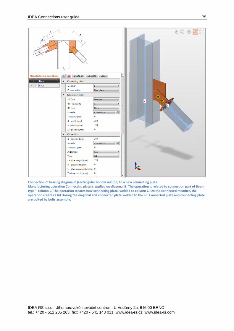
IDEA Connections user guide 75
IDEA RS s.r.o. | Jihomoravské inovační centrum, U Vodárny 2a, 616 00 BRNO
tel.: +420 - 511 205 263, fax: +420 - 541 143 011, www.idea-rs.cz, www.idea-rs.com
Connection of bracing diagonal B (rectangular hollow section) to a new connecting plate. Manufacturing operation Connecting plate is applied on diagonal B. The operation is related to connection part of Beam type – column C. The operation creates new connecting plate, welded to column C. On the connected member, the operation creates a lid closing the diagonal and connected plate welded to the lid. Connected plate and connecting plate are bolted by bolts assembly.
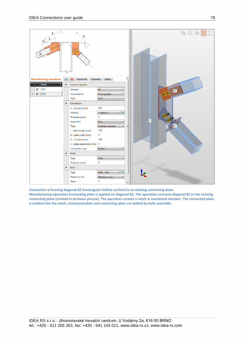
IDEA Connections user guide 76
IDEA RS s.r.o. | Jihomoravské inovační centrum, U Vodárny 2a, 616 00 BRNO
tel.: +420 - 511 205 263, fax: +420 - 541 143 011, www.idea-rs.cz, www.idea-rs.com
Connection of bracing diagonal B2 (rectangular hollow section) to an existing connecting plate. Manufacturing operation Connecting plate is applied on diagonal B2. The operation connects diagonal B2 to the existing connecting plate (created in previous picture). The operation creates a notch in connected member. The connected plate is welded into the notch. Connected plate and connecting plate are bolted by bolts assembly.
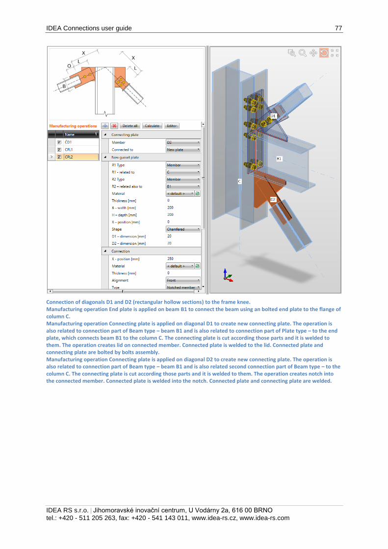
IDEA Connections user guide 77
IDEA RS s.r.o. | Jihomoravské inovační centrum, U Vodárny 2a, 616 00 BRNO
tel.: +420 - 511 205 263, fax: +420 - 541 143 011, www.idea-rs.cz, www.idea-rs.com
Connection of diagonals D1 and D2 (rectangular hollow sections) to the frame knee. Manufacturing operation End plate is applied on beam B1 to connect the beam using an bolted end plate to the flange of column C. Manufacturing operation Connecting plate is applied on diagonal D1 to create new connecting plate. The operation is also related to connection part of Beam type – beam B1 and is also related to connection part of Plate type – to the end plate, which connects beam B1 to the column C. The connecting plate is cut according those parts and it is welded to them. The operation creates lid on connected member. Connected plate is welded to the lid. Connected plate and connecting plate are bolted by bolts assembly. Manufacturing operation Connecting plate is applied on diagonal D2 to create new connecting plate. The operation is also related to connection part of Beam type – beam B1 and is also related second connection part of Beam type – to the column C. The connecting plate is cut according those parts and it is welded to them. The operation creates notch into the connected member. Connected plate is welded into the notch. Connected plate and connecting plate are welded.
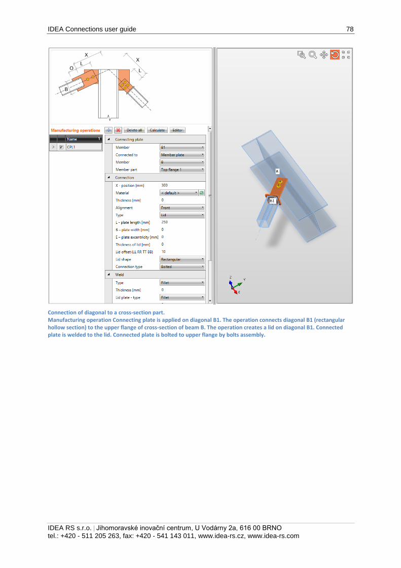
IDEA Connections user guide 78
IDEA RS s.r.o. | Jihomoravské inovační centrum, U Vodárny 2a, 616 00 BRNO
tel.: +420 - 511 205 263, fax: +420 - 541 143 011, www.idea-rs.cz, www.idea-rs.com
Connection of diagonal to a cross-section part. Manufacturing operation Connecting plate is applied on diagonal B1. The operation connects diagonal B1 (rectangular hollow section) to the upper flange of cross-section of beam B. The operation creates a lid on diagonal B1. Connected plate is welded to the lid. Connected plate is bolted to upper flange by bolts assembly.
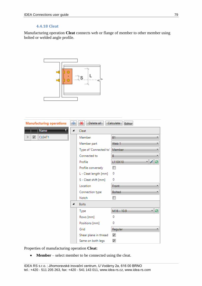
IDEA Connections user guide 79
IDEA RS s.r.o. | Jihomoravské inovační centrum, U Vodárny 2a, 616 00 BRNO
tel.: +420 - 511 205 263, fax: +420 - 541 143 011, www.idea-rs.cz, www.idea-rs.com
4.4.18 Cleat
Manufacturing operation Cleat connects web or flange of member to other member using
bolted or welded angle profile.
Properties of manufacturing operation Cleat:
Member – select member to be connected using the cleat.
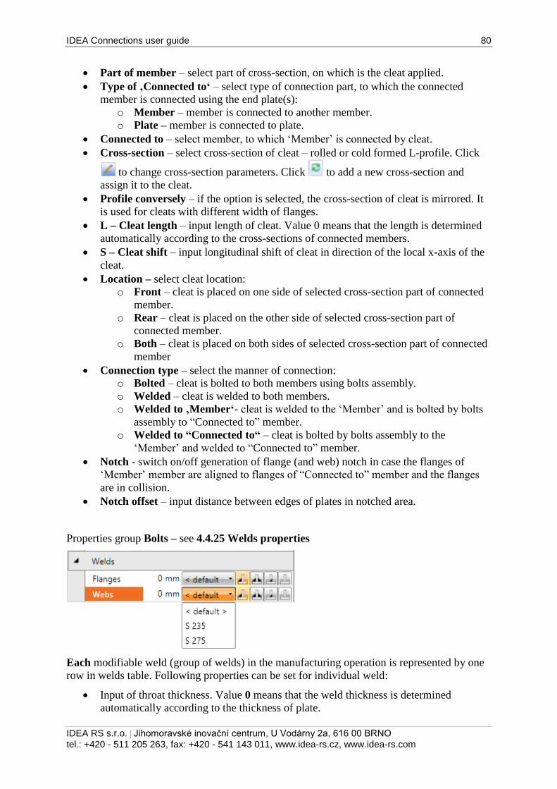
IDEA Connections user guide 80
IDEA RS s.r.o. | Jihomoravské inovační centrum, U Vodárny 2a, 616 00 BRNO
tel.: +420 - 511 205 263, fax: +420 - 541 143 011, www.idea-rs.cz, www.idea-rs.com
Part of member – select part of cross-section, on which is the cleat applied.
Type of ‚Connected to‘ – select type of connection part, to which the connected
member is connected using the end plate(s):
o Member – member is connected to another member.
o Plate – member is connected to plate.
Connected to – select member, to which ‘Member’ is connected by cleat.
Cross-section – select cross-section of cleat – rolled or cold formed L-profile. Click
to change cross-section parameters. Click to add a new cross-section and
assign it to the cleat.
Profile conversely – if the option is selected, the cross-section of cleat is mirrored. It
is used for cleats with different width of flanges.
L – Cleat length – input length of cleat. Value 0 means that the length is determined
automatically according to the cross-sections of connected members.
S – Cleat shift – input longitudinal shift of cleat in direction of the local x-axis of the
cleat.
Location – select cleat location:
o Front – cleat is placed on one side of selected cross-section part of connected
member.
o Rear – cleat is placed on the other side of selected cross-section part of
connected member.
o Both – cleat is placed on both sides of selected cross-section part of connected
member
Connection type – select the manner of connection:
o Bolted – cleat is bolted to both members using bolts assembly.
o Welded – cleat is welded to both members.
o Welded to ‚Member‘- cleat is welded to the ‘Member’ and is bolted by bolts
assembly to “Connected to” member.
o Welded to “Connected to“ – cleat is bolted by bolts assembly to the
‘Member’ and welded to “Connected to” member.
Notch - switch on/off generation of flange (and web) notch in case the flanges of
‘Member’ member are aligned to flanges of “Connected to” member and the flanges
are in collision.
Notch offset – input distance between edges of plates in notched area.
Properties group Bolts – see 4.4.25 Welds properties
Each modifiable weld (group of welds) in the manufacturing operation is represented by one
row in welds table. Following properties can be set for individual weld:
Input of throat thickness. Value 0 means that the weld thickness is determined
automatically according to the thickness of plate.
IDEA Connections user guide 81
IDEA RS s.r.o. | Jihomoravské inovační centrum, U Vodárny 2a, 616 00 BRNO
tel.: +420 - 511 205 263, fax: +420 - 541 143 011, www.idea-rs.cz, www.idea-rs.com
Select material of weld. Material <default> means that material is determined
automatically according to the material of corresponding plate.
- switch the weld type to fillet weld.
- switch the weld type to double fillet weld.
- switch the weld type to butt weld.
- switch the off – plates are not connected in the appropriate area of weld.
4.4.19 Input of bolts by layers
Following properties are available to define bolts or anchors positions related to plate edge or
cross-section centroid:
Type – select bolts assembly. Click to add new bolts assembly.
For plate dimensions defined to profile edges the bolts are defined by:
TL – Top layers – input distances of bolt layers (separated by spaces) from the most
outer left edge of cross-section.
LL – Left layers – input distances of bolt layers (separated by spaces) from the most
outer top edge of cross-section.
BL – Bottom layers – input distances of bolt layers (separated by spaces) from the
most outer bottom edge of cross-section.
RL – Right layers – input distances of bolt layers (separated by spaces) from the most
outer right edge of cross-section.
For plate dimensions defined by rectangle the bolts are defined by:
H – Horizontal layers – input distances of horizontal bolt layers (separated by
spaces) from the centroid of plate.
V – Vertical layers – – input distances of vertical bolt layers (separated by spaces)
from the centroid of plate.
Bolts for circular plate are defined by:
Radius – input radius of bolts pitch circle.
Number – input number of bolts on the pitch circle.
Shear plane in thread – if selected, the gross area of bolt (reduced by thread) is taken
into account in the bolts check.
Input of bolt assembly. The change of reference line is not allowed, bolts are related to the
centroid of individual cleat flanges.
Same on both legs – if not selected, the different bolts assembly can be specified for
each leg of cleat, otherwise the bolt assembly definition is common for both legs.
Properties group Welds – input of welds properties – see 4.4.25 Welds properties:
Member – properties of weld between cleat and connected member.
Connected to - properties of weld between cleat and ‚Connected to‘ member.
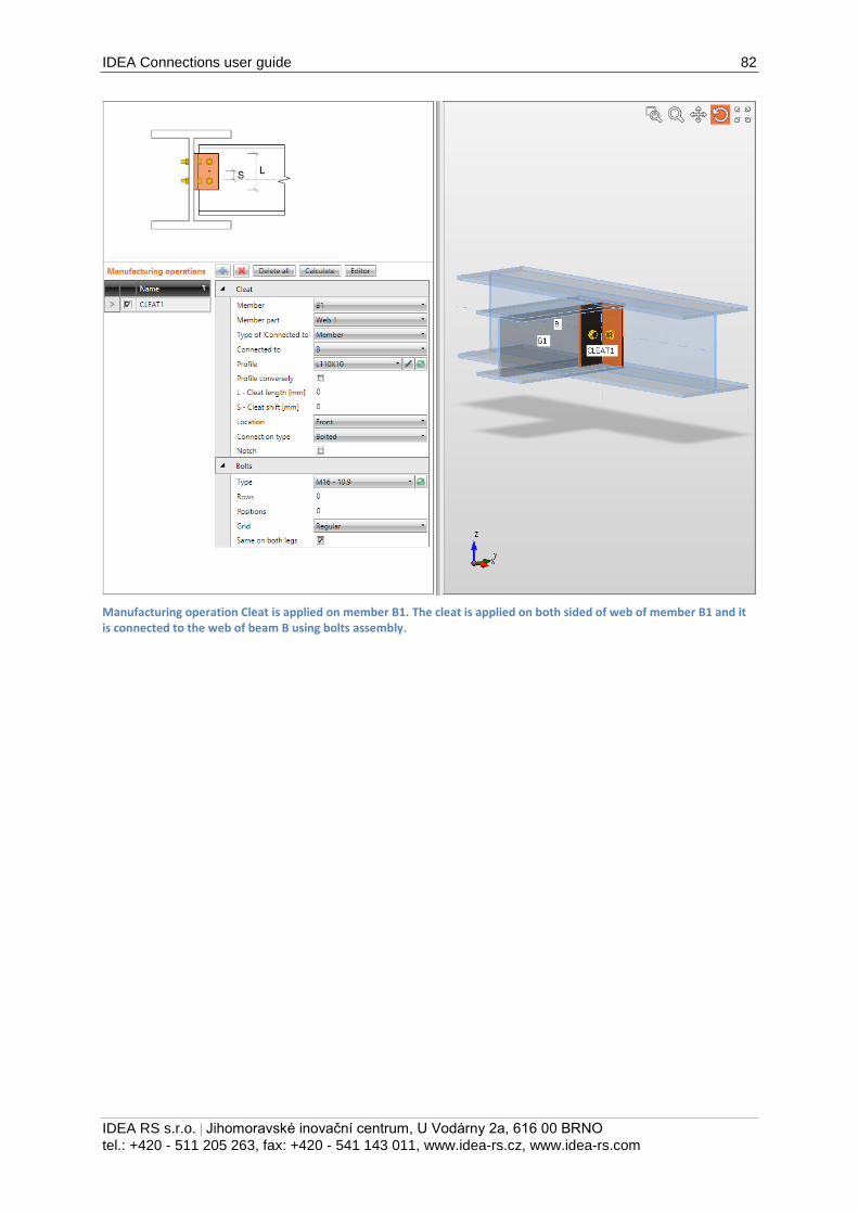
IDEA Connections user guide 82
IDEA RS s.r.o. | Jihomoravské inovační centrum, U Vodárny 2a, 616 00 BRNO
tel.: +420 - 511 205 263, fax: +420 - 541 143 011, www.idea-rs.cz, www.idea-rs.com
Manufacturing operation Cleat is applied on member B1. The cleat is applied on both sided of web of member B1 and it is connected to the web of beam B using bolts assembly.
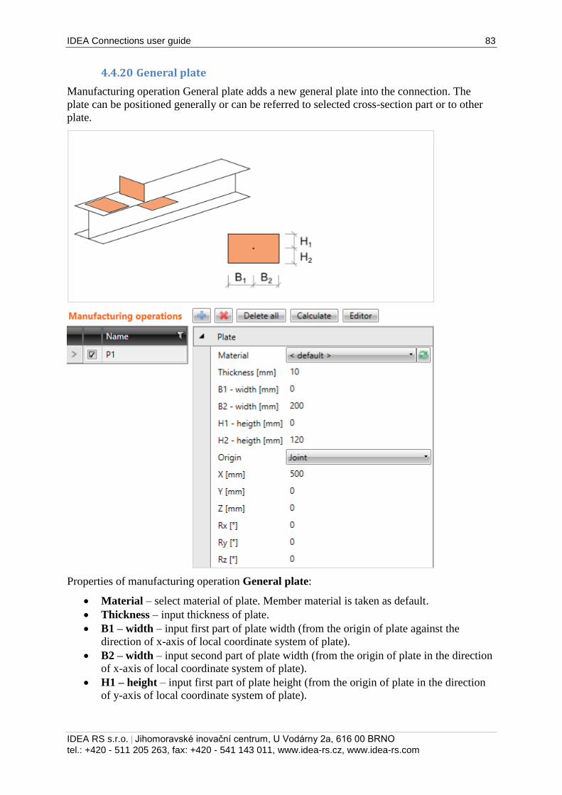
IDEA Connections user guide 83
IDEA RS s.r.o. | Jihomoravské inovační centrum, U Vodárny 2a, 616 00 BRNO
tel.: +420 - 511 205 263, fax: +420 - 541 143 011, www.idea-rs.cz, www.idea-rs.com
4.4.20 General plate
Manufacturing operation General plate adds a new general plate into the connection. The
plate can be positioned generally or can be referred to selected cross-section part or to other
plate.
Properties of manufacturing operation General plate:
Material – select material of plate. Member material is taken as default.
Thickness – input thickness of plate.
B1 – width – input first part of plate width (from the origin of plate against the
direction of x-axis of local coordinate system of plate).
B2 – width – input second part of plate width (from the origin of plate in the direction
of x-axis of local coordinate system of plate).
H1 – height – input first part of plate height (from the origin of plate in the direction
of y-axis of local coordinate system of plate).
IDEA Connections user guide 84
IDEA RS s.r.o. | Jihomoravské inovační centrum, U Vodárny 2a, 616 00 BRNO
tel.: +420 - 511 205 263, fax: +420 - 541 143 011, www.idea-rs.cz, www.idea-rs.com
H2 – height – input second part of plate height (from the origin of plate against the
direction of y-axis of local coordinate system of plate).
Origin – select origin to define the position of the plate:
o Joint – position of plate origin is related to the theoretical origin of the whole
joint. Plate related to joint origin is not connected to any connection part. It
must be connected by other manufacturing operations (plate cut, bolts
group…).
o Member – position of plate origin is related to the selected cross-section part
of selected member.
o Plate – position of plate origin is related to another selected plate.
Following properties can be defined for the plate related to the joint origin:
X – input distance of plate origin from joint origin in direction of global X-axis.
Y – input distance of plate origin from joint origin in direction of global Y-axis .
Z – input distance of plate origin from joint origin in direction of global Z-axis.
Rx – input rotation about axis through the plate origin and parallel to the global X-
axis.
Ry – input rotation about axis through the plate origin and parallel to the global Y-
axis.
Rz – input rotation about axis through the plate origin and parallel to the global Z-
axis.
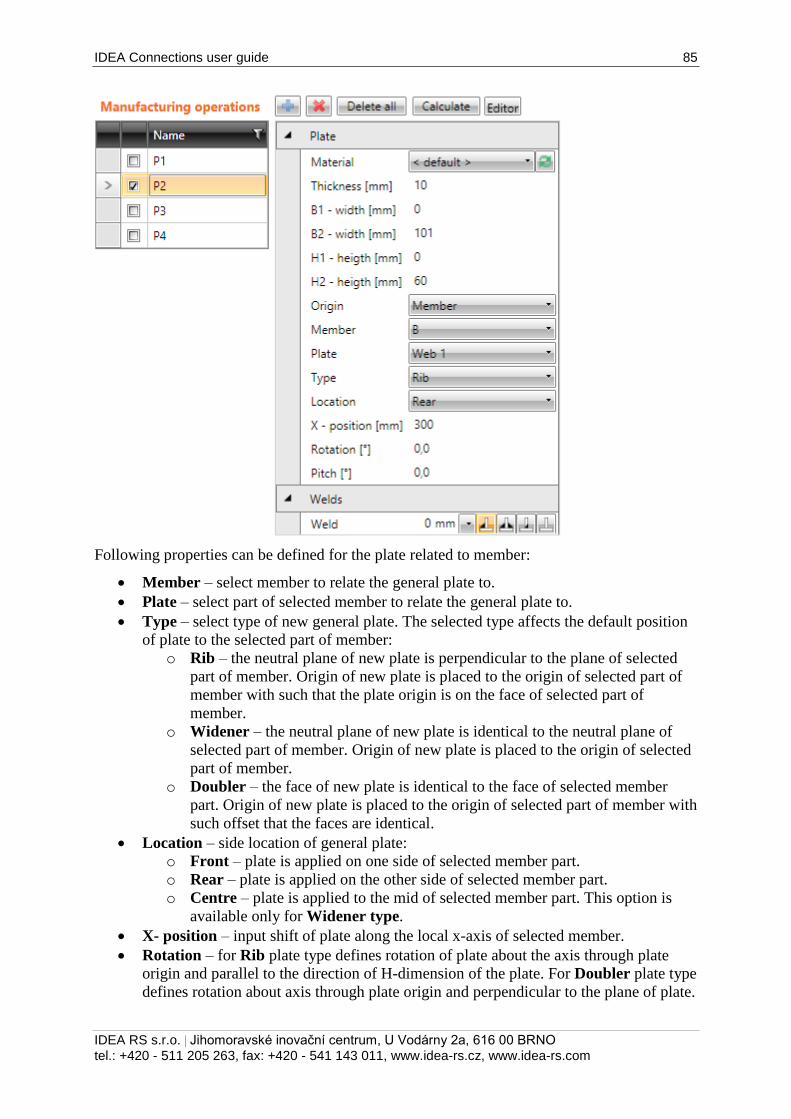
IDEA Connections user guide 85
IDEA RS s.r.o. | Jihomoravské inovační centrum, U Vodárny 2a, 616 00 BRNO
tel.: +420 - 511 205 263, fax: +420 - 541 143 011, www.idea-rs.cz, www.idea-rs.com
Following properties can be defined for the plate related to member:
Member – select member to relate the general plate to.
Plate – select part of selected member to relate the general plate to.
Type – select type of new general plate. The selected type affects the default position
of plate to the selected part of member:
o Rib – the neutral plane of new plate is perpendicular to the plane of selected
part of member. Origin of new plate is placed to the origin of selected part of
member with such that the plate origin is on the face of selected part of
member.
o Widener – the neutral plane of new plate is identical to the neutral plane of
selected part of member. Origin of new plate is placed to the origin of selected
part of member.
o Doubler – the face of new plate is identical to the face of selected member
part. Origin of new plate is placed to the origin of selected part of member with
such offset that the faces are identical.
Location – side location of general plate:
o Front – plate is applied on one side of selected member part.
o Rear – plate is applied on the other side of selected member part.
o Centre – plate is applied to the mid of selected member part. This option is
available only for Widener type.
X- position – input shift of plate along the local x-axis of selected member.
Rotation – for Rib plate type defines rotation of plate about the axis through plate
origin and parallel to the direction of H-dimension of the plate. For Doubler plate type
defines rotation about axis through plate origin and perpendicular to the plane of plate.
IDEA Connections user guide 86
IDEA RS s.r.o. | Jihomoravské inovační centrum, U Vodárny 2a, 616 00 BRNO
tel.: +420 - 511 205 263, fax: +420 - 541 143 011, www.idea-rs.cz, www.idea-rs.com
Pitch – for Rib plate type defines inclination of plate plane from the normal of
selected member part. For Widener plate type defines inclination of plate plane from
the plane of selected member part.
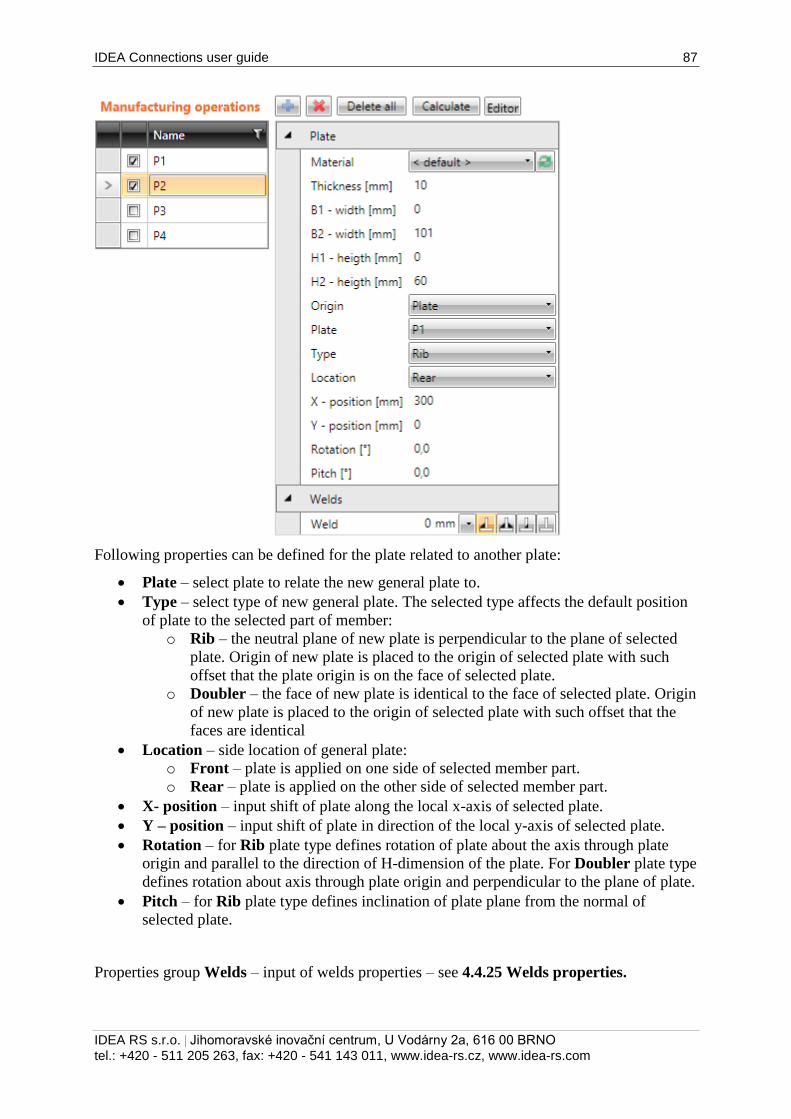
IDEA Connections user guide 87
IDEA RS s.r.o. | Jihomoravské inovační centrum, U Vodárny 2a, 616 00 BRNO
tel.: +420 - 511 205 263, fax: +420 - 541 143 011, www.idea-rs.cz, www.idea-rs.com
Following properties can be defined for the plate related to another plate:
Plate – select plate to relate the new general plate to.
Type – select type of new general plate. The selected type affects the default position
of plate to the selected part of member:
o Rib – the neutral plane of new plate is perpendicular to the plane of selected
plate. Origin of new plate is placed to the origin of selected plate with such
offset that the plate origin is on the face of selected plate.
o Doubler – the face of new plate is identical to the face of selected plate. Origin
of new plate is placed to the origin of selected plate with such offset that the
faces are identical
Location – side location of general plate:
o Front – plate is applied on one side of selected member part.
o Rear – plate is applied on the other side of selected member part.
X- position – input shift of plate along the local x-axis of selected plate.
Y – position – input shift of plate in direction of the local y-axis of selected plate.
Rotation – for Rib plate type defines rotation of plate about the axis through plate
origin and parallel to the direction of H-dimension of the plate. For Doubler plate type
defines rotation about axis through plate origin and perpendicular to the plane of plate.
Pitch – for Rib plate type defines inclination of plate plane from the normal of
selected plate.
Properties group Welds – input of welds properties – see 4.4.25 Welds properties.
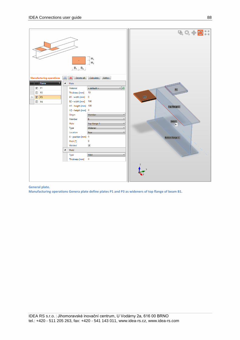
IDEA Connections user guide 88
IDEA RS s.r.o. | Jihomoravské inovační centrum, U Vodárny 2a, 616 00 BRNO
tel.: +420 - 511 205 263, fax: +420 - 541 143 011, www.idea-rs.cz, www.idea-rs.com
General plate. Manufacturing operations Genera plate define plates P1 and P3 as wideners of top flange of beam B1.
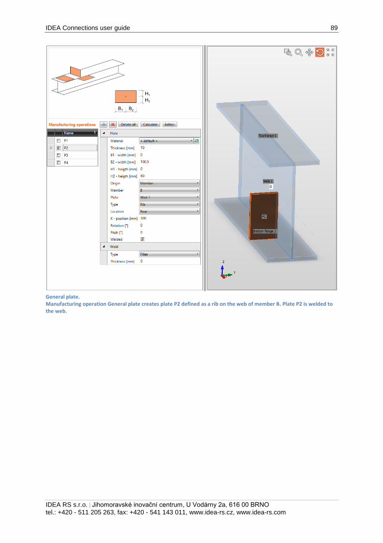
IDEA Connections user guide 89
IDEA RS s.r.o. | Jihomoravské inovační centrum, U Vodárny 2a, 616 00 BRNO
tel.: +420 - 511 205 263, fax: +420 - 541 143 011, www.idea-rs.cz, www.idea-rs.com
General plate. Manufacturing operation General plate creates plate P2 defined as a rib on the web of member B. Plate P2 is welded to the web.
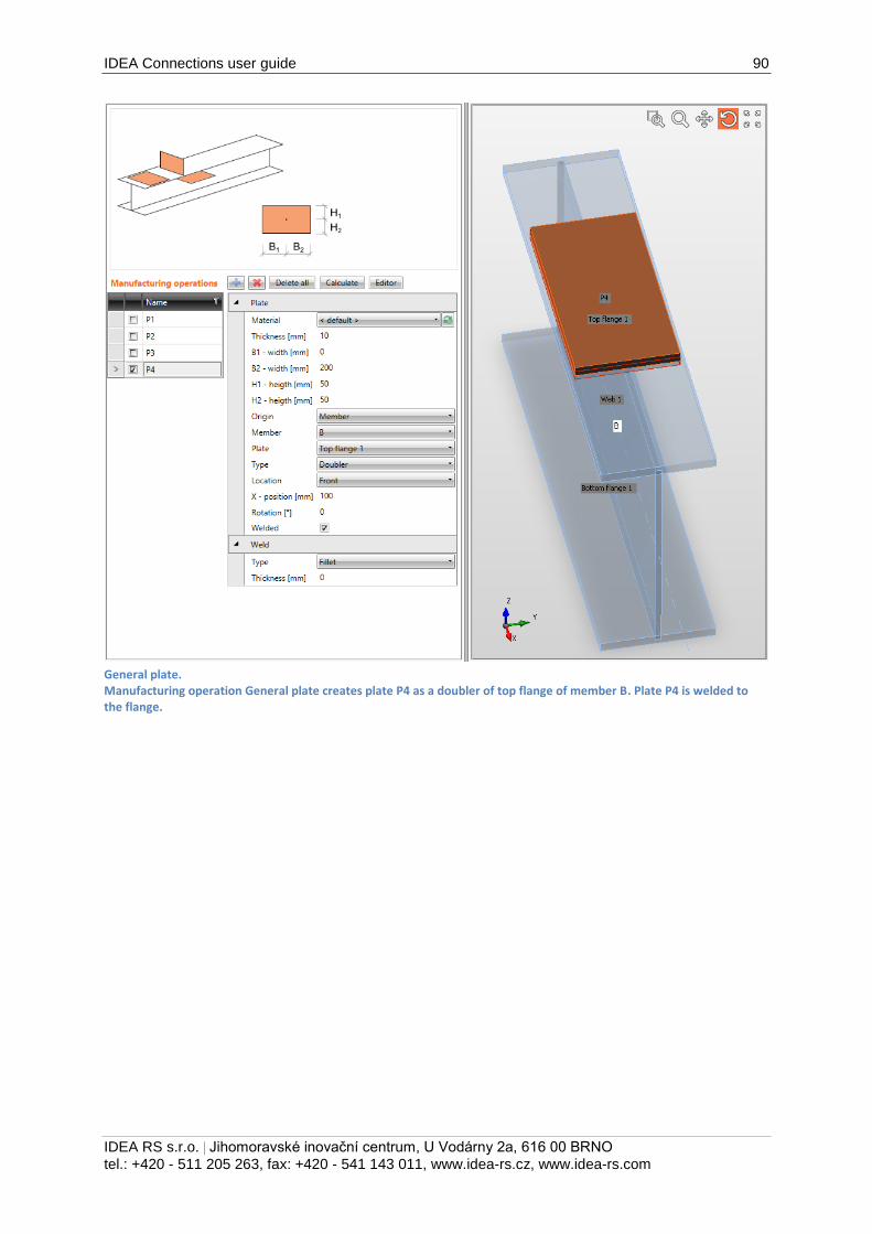
IDEA Connections user guide 90
IDEA RS s.r.o. | Jihomoravské inovační centrum, U Vodárny 2a, 616 00 BRNO
tel.: +420 - 511 205 263, fax: +420 - 541 143 011, www.idea-rs.cz, www.idea-rs.com
General plate. Manufacturing operation General plate creates plate P4 as a doubler of top flange of member B. Plate P4 is welded to the flange.
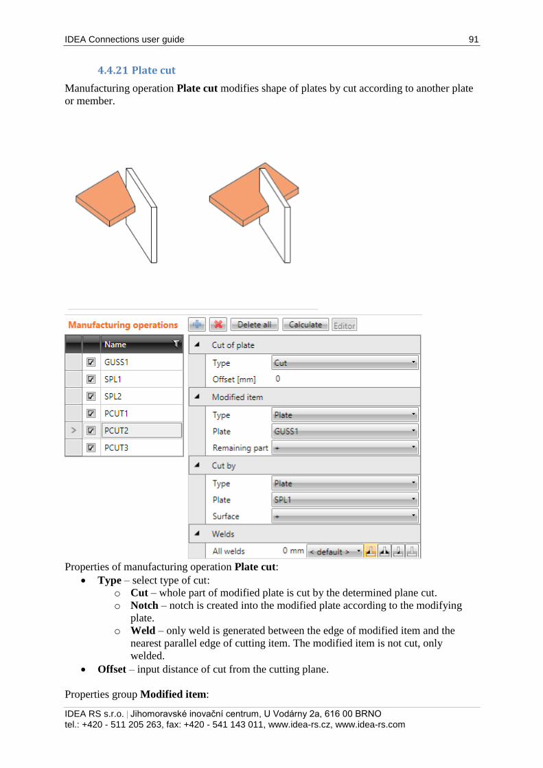
IDEA Connections user guide 91
IDEA RS s.r.o. | Jihomoravské inovační centrum, U Vodárny 2a, 616 00 BRNO
tel.: +420 - 511 205 263, fax: +420 - 541 143 011, www.idea-rs.cz, www.idea-rs.com
4.4.21 Plate cut
Manufacturing operation Plate cut modifies shape of plates by cut according to another plate
or member.
Properties of manufacturing operation Plate cut:
Type – select type of cut:
o Cut – whole part of modified plate is cut by the determined plane cut.
o Notch – notch is created into the modified plate according to the modifying
plate.
o Weld – only weld is generated between the edge of modified item and the
nearest parallel edge of cutting item. The modified item is not cut, only
welded.
Offset – input distance of cut from the cutting plane.
Properties group Modified item:
IDEA Connections user guide 92
IDEA RS s.r.o. | Jihomoravské inovační centrum, U Vodárny 2a, 616 00 BRNO
tel.: +420 - 511 205 263, fax: +420 - 541 143 011, www.idea-rs.cz, www.idea-rs.com
Type – select type of item, which is modified by cut:
o Member – plate of cross-section part of member is modified by cut. Following
properties are defined for this type:
Member – select member to modify its part.
Member part – select member part to be modified by plate cut.
o Plate – existing plate of joint is modified by cut. Following properties are
defined for this type:
Plate – select plate to be modified by cut.
Remaining part– select part of modified plate, which should be kept after cutting.
The other part is removed:
o + - one part of plate is kept after cutting.
o - - the other part of plate is kept after cutting.
Properties group Cut by – properties of modifying item:
Type – select type of modifying member:
o Plate – cut of modified plate is performed according to another plate.
Following properties are defined for this type:
Plate – select exiting plate to cut the modified item by it.
o Member plate – cut of modified plate is performed according to selected part
of member. Following properties are defined for this type:
Member – select member to cut the modified item by its part.
Member part – select part of member to be used as modifying item.
o Member – cut of modified plate is performed according to plane perpendicular
to the x-axis of selected member in the end point of the member. Following
properties are defined for this type:
Member – select member to perform the cut according to its end plane.
Surface – select surface of modifying plate (member part) to be used as the cutting
plane:
+ - cutting plane is created by one surface of plate.
- - cutting plane is created by the other surface of plate.
Properties group Welds – input of welds properties – see 4.4.25 Welds properties.
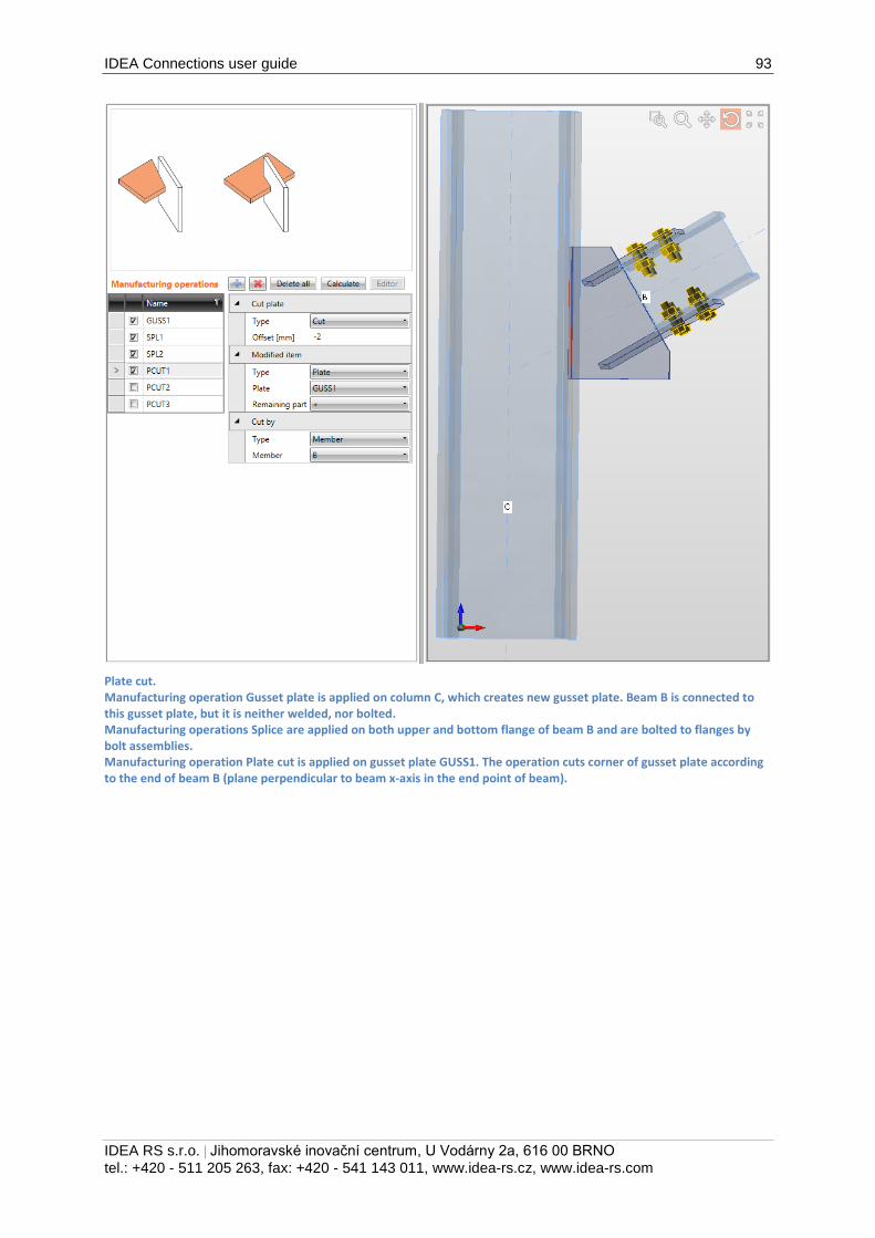
IDEA Connections user guide 93
IDEA RS s.r.o. | Jihomoravské inovační centrum, U Vodárny 2a, 616 00 BRNO
tel.: +420 - 511 205 263, fax: +420 - 541 143 011, www.idea-rs.cz, www.idea-rs.com
Plate cut. Manufacturing operation Gusset plate is applied on column C, which creates new gusset plate. Beam B is connected to this gusset plate, but it is neither welded, nor bolted. Manufacturing operations Splice are applied on both upper and bottom flange of beam B and are bolted to flanges by bolt assemblies. Manufacturing operation Plate cut is applied on gusset plate GUSS1. The operation cuts corner of gusset plate according to the end of beam B (plane perpendicular to beam x-axis in the end point of beam).
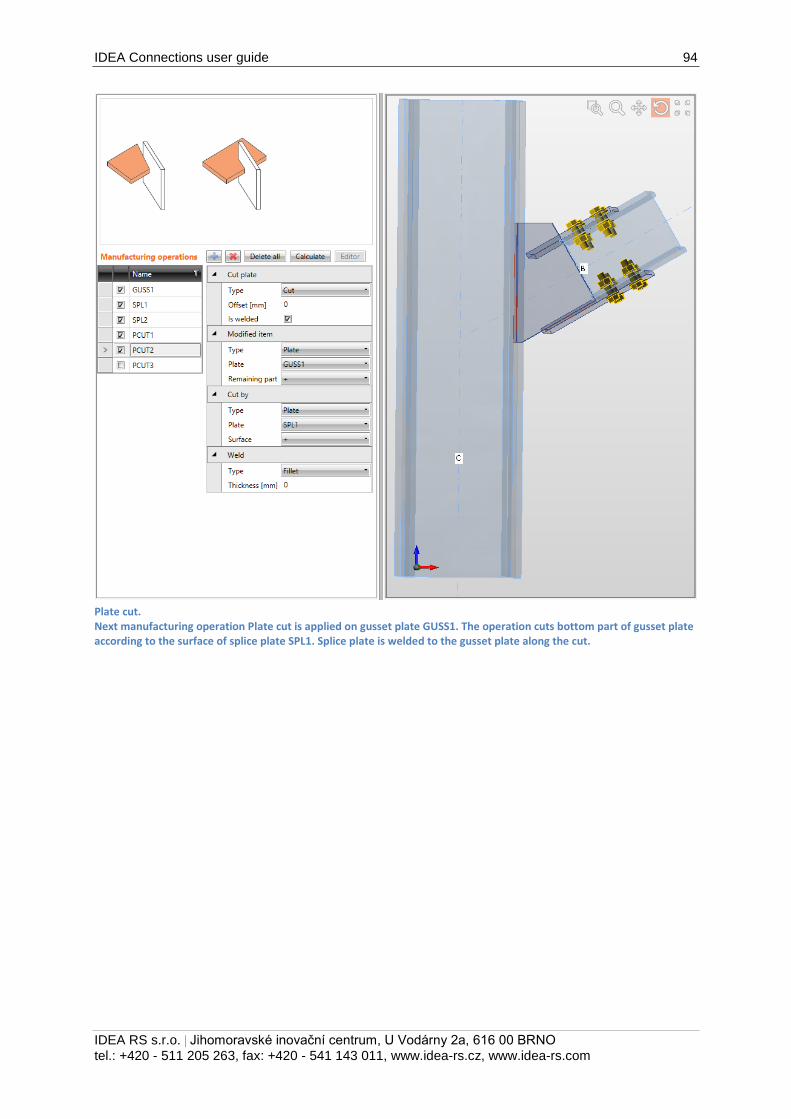
IDEA Connections user guide 94
IDEA RS s.r.o. | Jihomoravské inovační centrum, U Vodárny 2a, 616 00 BRNO
tel.: +420 - 511 205 263, fax: +420 - 541 143 011, www.idea-rs.cz, www.idea-rs.com
Plate cut. Next manufacturing operation Plate cut is applied on gusset plate GUSS1. The operation cuts bottom part of gusset plate according to the surface of splice plate SPL1. Splice plate is welded to the gusset plate along the cut.
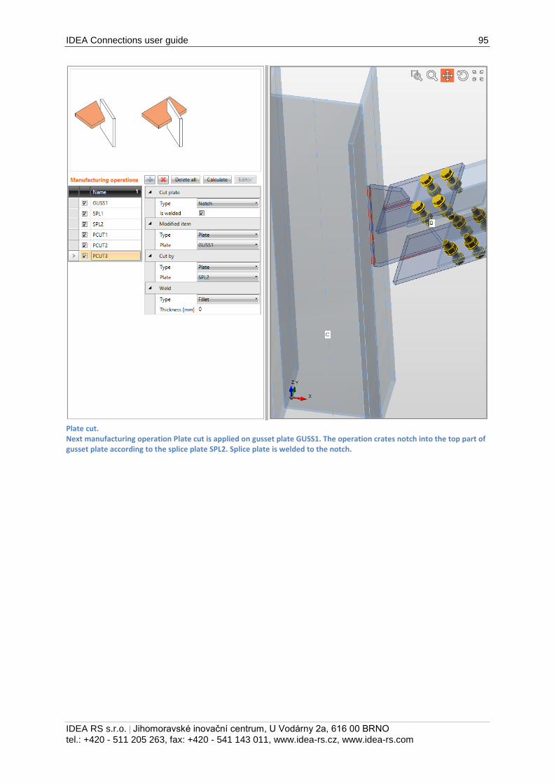
IDEA Connections user guide 95
IDEA RS s.r.o. | Jihomoravské inovační centrum, U Vodárny 2a, 616 00 BRNO
tel.: +420 - 511 205 263, fax: +420 - 541 143 011, www.idea-rs.cz, www.idea-rs.com
Plate cut. Next manufacturing operation Plate cut is applied on gusset plate GUSS1. The operation crates notch into the top part of gusset plate according to the splice plate SPL2. Splice plate is welded to the notch.
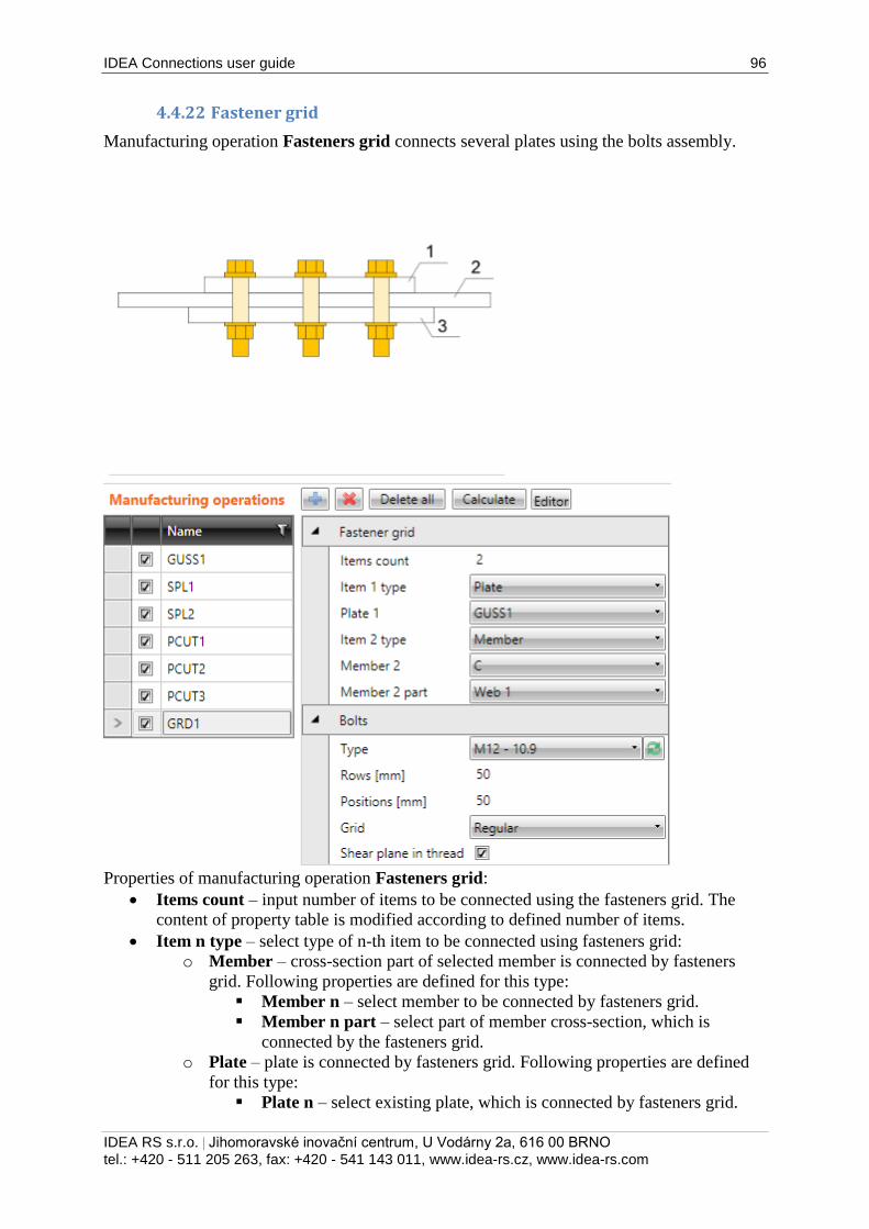
IDEA Connections user guide 96
IDEA RS s.r.o. | Jihomoravské inovační centrum, U Vodárny 2a, 616 00 BRNO
tel.: +420 - 511 205 263, fax: +420 - 541 143 011, www.idea-rs.cz, www.idea-rs.com
4.4.22 Fastener grid
Manufacturing operation Fasteners grid connects several plates using the bolts assembly.
Properties of manufacturing operation Fasteners grid:
Items count – input number of items to be connected using the fasteners grid. The
content of property table is modified according to defined number of items.
Item n type – select type of n-th item to be connected using fasteners grid:
o Member – cross-section part of selected member is connected by fasteners
grid. Following properties are defined for this type:
Member n – select member to be connected by fasteners grid.
Member n part – select part of member cross-section, which is
connected by the fasteners grid.
o Plate – plate is connected by fasteners grid. Following properties are defined
for this type:
Plate n – select existing plate, which is connected by fasteners grid.
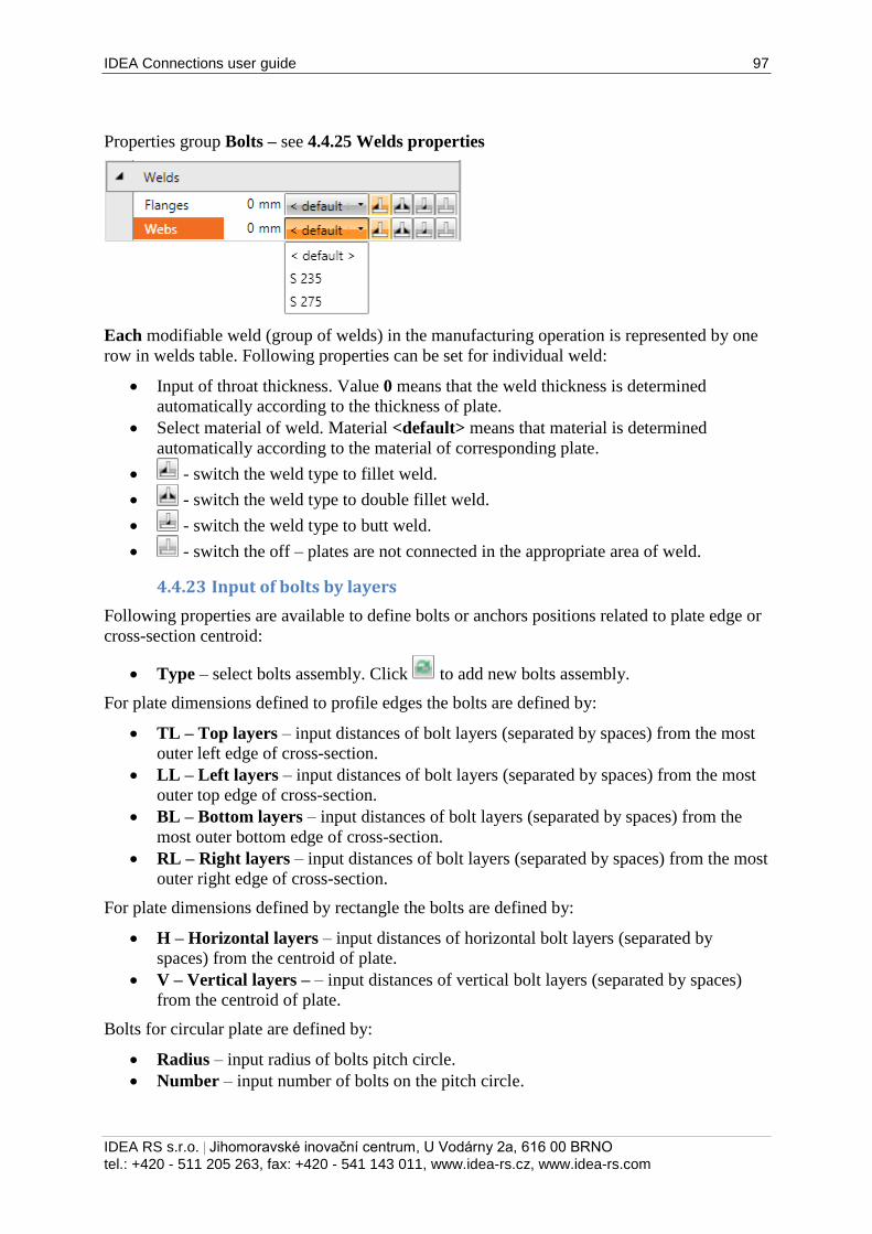
IDEA Connections user guide 97
IDEA RS s.r.o. | Jihomoravské inovační centrum, U Vodárny 2a, 616 00 BRNO
tel.: +420 - 511 205 263, fax: +420 - 541 143 011, www.idea-rs.cz, www.idea-rs.com
Properties group Bolts – see 4.4.25 Welds properties
Each modifiable weld (group of welds) in the manufacturing operation is represented by one
row in welds table. Following properties can be set for individual weld:
Input of throat thickness. Value 0 means that the weld thickness is determined
automatically according to the thickness of plate.
Select material of weld. Material <default> means that material is determined
automatically according to the material of corresponding plate.
- switch the weld type to fillet weld.
- switch the weld type to double fillet weld.
- switch the weld type to butt weld.
- switch the off – plates are not connected in the appropriate area of weld.
4.4.23 Input of bolts by layers
Following properties are available to define bolts or anchors positions related to plate edge or
cross-section centroid:
Type – select bolts assembly. Click to add new bolts assembly.
For plate dimensions defined to profile edges the bolts are defined by:
TL – Top layers – input distances of bolt layers (separated by spaces) from the most
outer left edge of cross-section.
LL – Left layers – input distances of bolt layers (separated by spaces) from the most
outer top edge of cross-section.
BL – Bottom layers – input distances of bolt layers (separated by spaces) from the
most outer bottom edge of cross-section.
RL – Right layers – input distances of bolt layers (separated by spaces) from the most
outer right edge of cross-section.
For plate dimensions defined by rectangle the bolts are defined by:
H – Horizontal layers – input distances of horizontal bolt layers (separated by
spaces) from the centroid of plate.
V – Vertical layers – – input distances of vertical bolt layers (separated by spaces)
from the centroid of plate.
Bolts for circular plate are defined by:
Radius – input radius of bolts pitch circle.
Number – input number of bolts on the pitch circle.
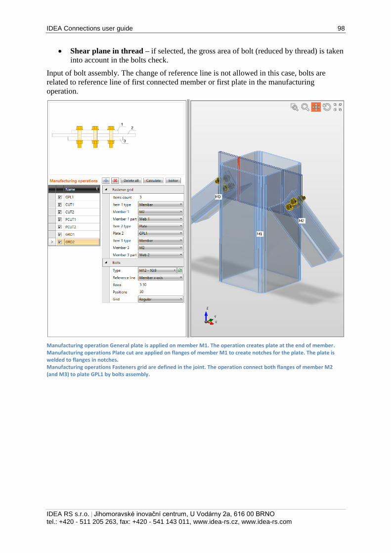
IDEA Connections user guide 98
IDEA RS s.r.o. | Jihomoravské inovační centrum, U Vodárny 2a, 616 00 BRNO
tel.: +420 - 511 205 263, fax: +420 - 541 143 011, www.idea-rs.cz, www.idea-rs.com
Shear plane in thread – if selected, the gross area of bolt (reduced by thread) is taken
into account in the bolts check.
Input of bolt assembly. The change of reference line is not allowed in this case, bolts are
related to reference line of first connected member or first plate in the manufacturing
operation.
Manufacturing operation General plate is applied on member M1. The operation creates plate at the end of member. Manufacturing operations Plate cut are applied on flanges of member M1 to create notches for the plate. The plate is welded to flanges in notches. Manufacturing operations Fasteners grid are defined in the joint. The operation connect both flanges of member M2 (and M3) to plate GPL1 by bolts assembly.
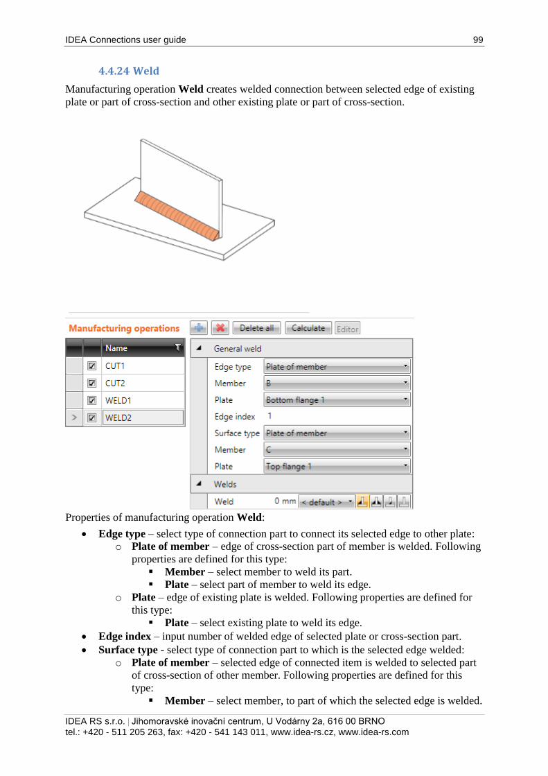
IDEA Connections user guide 99
IDEA RS s.r.o. | Jihomoravské inovační centrum, U Vodárny 2a, 616 00 BRNO
tel.: +420 - 511 205 263, fax: +420 - 541 143 011, www.idea-rs.cz, www.idea-rs.com
4.4.24 Weld
Manufacturing operation Weld creates welded connection between selected edge of existing
plate or part of cross-section and other existing plate or part of cross-section.
Properties of manufacturing operation Weld:
Edge type – select type of connection part to connect its selected edge to other plate:
o Plate of member – edge of cross-section part of member is welded. Following
properties are defined for this type:
Member – select member to weld its part.
Plate – select part of member to weld its edge.
o Plate – edge of existing plate is welded. Following properties are defined for
this type:
Plate – select existing plate to weld its edge.
Edge index – input number of welded edge of selected plate or cross-section part.
Surface type - select type of connection part to which is the selected edge welded:
o Plate of member – selected edge of connected item is welded to selected part
of cross-section of other member. Following properties are defined for this
type:
Member – select member, to part of which the selected edge is welded.
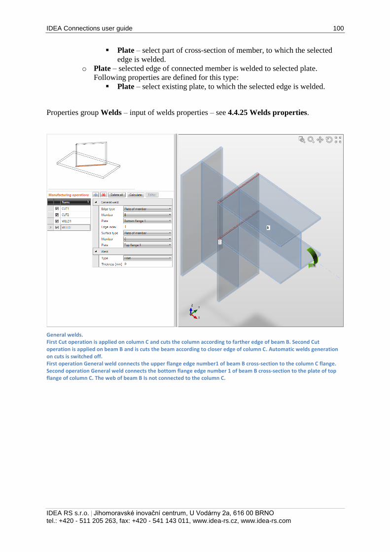
IDEA Connections user guide 100
IDEA RS s.r.o. | Jihomoravské inovační centrum, U Vodárny 2a, 616 00 BRNO
tel.: +420 - 511 205 263, fax: +420 - 541 143 011, www.idea-rs.cz, www.idea-rs.com
Plate – select part of cross-section of member, to which the selected
edge is welded.
o Plate – selected edge of connected member is welded to selected plate.
Following properties are defined for this type:
Plate – select existing plate, to which the selected edge is welded.
Properties group Welds – input of welds properties – see 4.4.25 Welds properties.
General welds. First Cut operation is applied on column C and cuts the column according to farther edge of beam B. Second Cut operation is applied on beam B and is cuts the beam according to closer edge of column C. Automatic welds generation on cuts is switched off. First operation General weld connects the upper flange edge number1 of beam B cross-section to the column C flange. Second operation General weld connects the bottom flange edge number 1 of beam B cross-section to the plate of top flange of column C. The web of beam B Is not connected to the column C.
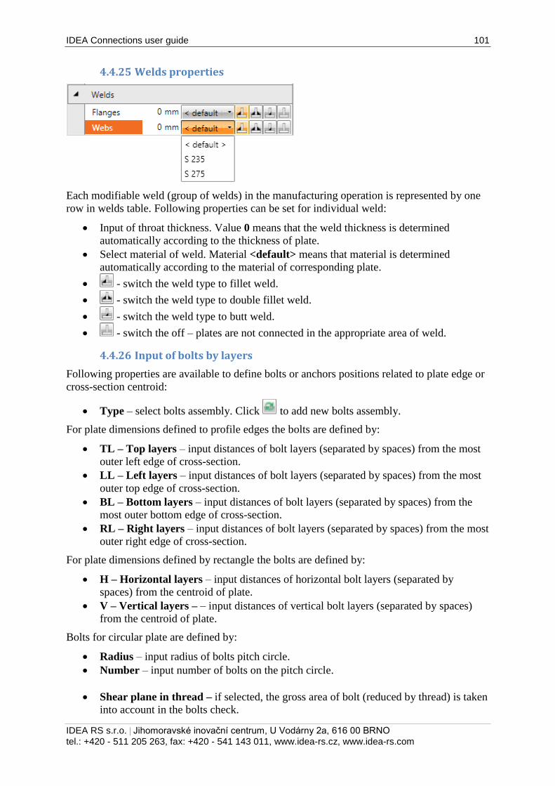
IDEA Connections user guide 101
IDEA RS s.r.o. | Jihomoravské inovační centrum, U Vodárny 2a, 616 00 BRNO
tel.: +420 - 511 205 263, fax: +420 - 541 143 011, www.idea-rs.cz, www.idea-rs.com
4.4.25 Welds properties
Each modifiable weld (group of welds) in the manufacturing operation is represented by one
row in welds table. Following properties can be set for individual weld:
Input of throat thickness. Value 0 means that the weld thickness is determined
automatically according to the thickness of plate.
Select material of weld. Material <default> means that material is determined
automatically according to the material of corresponding plate.
- switch the weld type to fillet weld.
- switch the weld type to double fillet weld.
- switch the weld type to butt weld.
- switch the off – plates are not connected in the appropriate area of weld.
4.4.26 Input of bolts by layers
Following properties are available to define bolts or anchors positions related to plate edge or
cross-section centroid:
Type – select bolts assembly. Click to add new bolts assembly.
For plate dimensions defined to profile edges the bolts are defined by:
TL – Top layers – input distances of bolt layers (separated by spaces) from the most
outer left edge of cross-section.
LL – Left layers – input distances of bolt layers (separated by spaces) from the most
outer top edge of cross-section.
BL – Bottom layers – input distances of bolt layers (separated by spaces) from the
most outer bottom edge of cross-section.
RL – Right layers – input distances of bolt layers (separated by spaces) from the most
outer right edge of cross-section.
For plate dimensions defined by rectangle the bolts are defined by:
H – Horizontal layers – input distances of horizontal bolt layers (separated by
spaces) from the centroid of plate.
V – Vertical layers – – input distances of vertical bolt layers (separated by spaces)
from the centroid of plate.
Bolts for circular plate are defined by:
Radius – input radius of bolts pitch circle.
Number – input number of bolts on the pitch circle.
Shear plane in thread – if selected, the gross area of bolt (reduced by thread) is taken
into account in the bolts check.
IDEA Connections user guide 102
IDEA RS s.r.o. | Jihomoravské inovační centrum, U Vodárny 2a, 616 00 BRNO
tel.: +420 - 511 205 263, fax: +420 - 541 143 011, www.idea-rs.cz, www.idea-rs.com
4.4.27 Input of bolt assembly
Following properties are available to define the bolts assembly:
Type – select bolts assembly. Click to add new bolts assembly.
Reference line – select line, to which the bolts positions are referred:
o Member x-axis – bolts positions are referred to the axis of appropriate cross-
section part.
o + edge - bolts positions are referred to the edge with positive coordinate of
appropriate cross-section part.
o – edge – bolts positions are referred to the edge with negative coordinate of
appropriate cross-section part.
Rows – input bolt rows positions (transversal spacing) to the reference line.
Positions – input bolts positions along x-axis of member (longitudinal spacing).
Positions of bolt centres for both transversal and longitudinal spacing are defined by
string in format a1 a2*n...an*n; b1 b2*m...b3*m, where ';' is group separator. For each
group (a, b,... etc.) a1 is position of first centre from the origin, a2*n - is pitch *
repeats count. For example 80 60*3 80; 500 60*3 80*2 creates two groups of bolt
rows, first group coordinates (to the reference line) are 80, 140, 200, 260, 340 and
second group coordinates are 500; 560; 620; 680; 760; 840.
Grid – select type of bolts grid:
o Regular – grid of bolts is regular.
o 1st staggered – first (and then each odd) bolts row is shifted by half of bolt
diameter.
o 2nd
staggered – second (a then each even) bolts row is shifted by half of bolt
diameter.
o 1st staggered short – first (and then each odd) bolts row is shifted by half of
bolt diameter. Last bolt in staggered row is omitted.
o 2nd
staggered short – second (a then each even) bolts row is shifted by half of
bolt diameter. Last bolt in staggered row is omitted.
Shear plane in thread – if selected, the gross area of bolt (reduced by thread) is taken
into account in the bolts check.
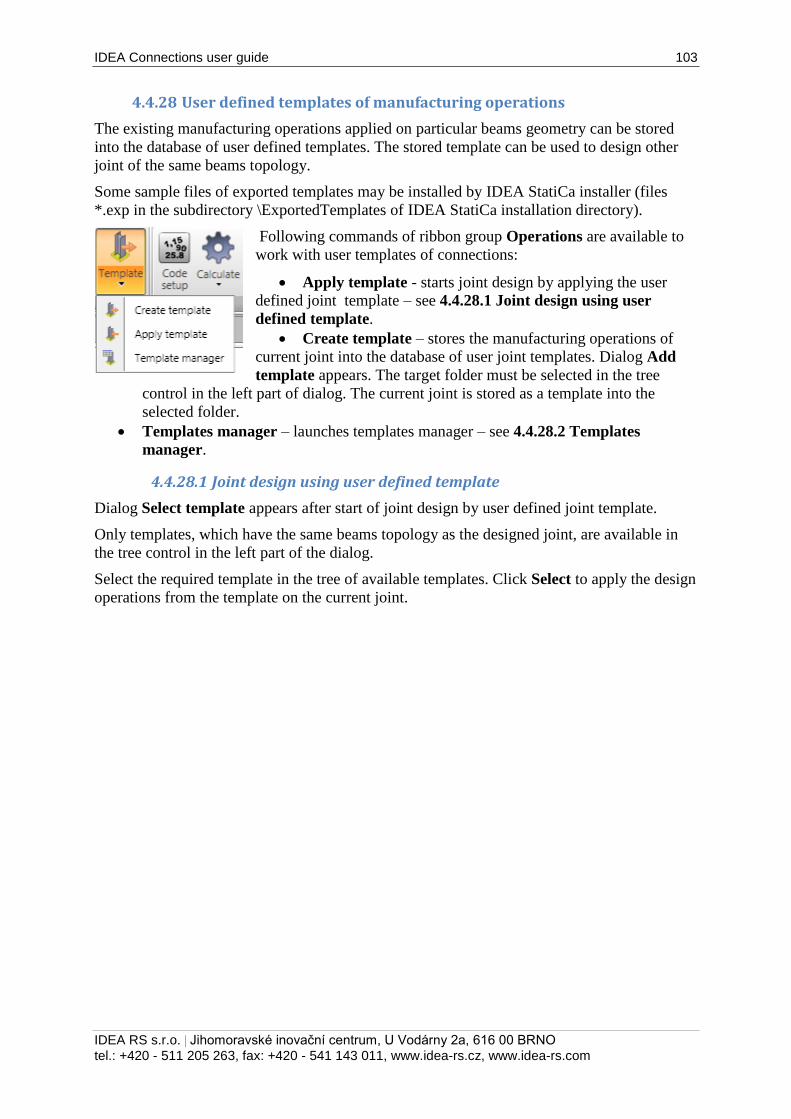
IDEA Connections user guide 103
IDEA RS s.r.o. | Jihomoravské inovační centrum, U Vodárny 2a, 616 00 BRNO
tel.: +420 - 511 205 263, fax: +420 - 541 143 011, www.idea-rs.cz, www.idea-rs.com
4.4.28 User defined templates of manufacturing operations
The existing manufacturing operations applied on particular beams geometry can be stored
into the database of user defined templates. The stored template can be used to design other
joint of the same beams topology.
Some sample files of exported templates may be installed by IDEA StatiCa installer (files
*.exp in the subdirectory \ExportedTemplates of IDEA StatiCa installation directory).
Following commands of ribbon group Operations are available to
work with user templates of connections:
Apply template - starts joint design by applying the user
defined joint template – see 4.4.28.1 Joint design using user
defined template.
Create template – stores the manufacturing operations of
current joint into the database of user joint templates. Dialog Add
template appears. The target folder must be selected in the tree
control in the left part of dialog. The current joint is stored as a template into the
selected folder.
Templates manager – launches templates manager – see 4.4.28.2 Templates
manager.
4.4.28.1 Joint design using user defined template
Dialog Select template appears after start of joint design by user defined joint template.
Only templates, which have the same beams topology as the designed joint, are available in
the tree control in the left part of the dialog.
Select the required template in the tree of available templates. Click Select to apply the design
operations from the template on the current joint.
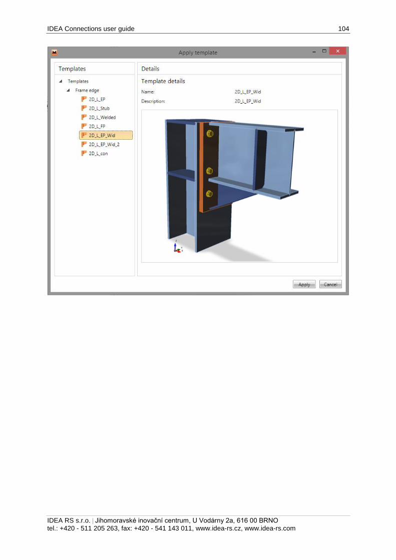
IDEA Connections user guide 104
IDEA RS s.r.o. | Jihomoravské inovační centrum, U Vodárny 2a, 616 00 BRNO
tel.: +420 - 511 205 263, fax: +420 - 541 143 011, www.idea-rs.cz, www.idea-rs.com
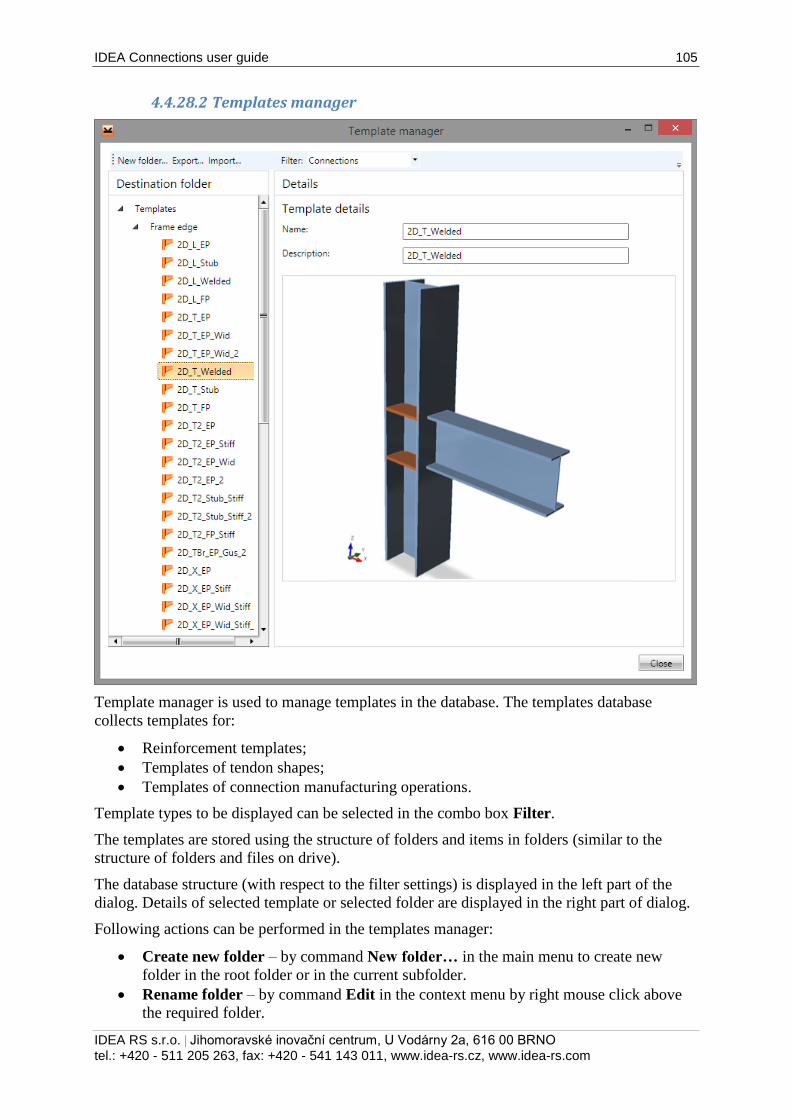
IDEA Connections user guide 105
IDEA RS s.r.o. | Jihomoravské inovační centrum, U Vodárny 2a, 616 00 BRNO
tel.: +420 - 511 205 263, fax: +420 - 541 143 011, www.idea-rs.cz, www.idea-rs.com
4.4.28.2 Templates manager
Template manager is used to manage templates in the database. The templates database
collects templates for:
Reinforcement templates;
Templates of tendon shapes;
Templates of connection manufacturing operations.
Template types to be displayed can be selected in the combo box Filter.
The templates are stored using the structure of folders and items in folders (similar to the
structure of folders and files on drive).
The database structure (with respect to the filter settings) is displayed in the left part of the
dialog. Details of selected template or selected folder are displayed in the right part of dialog.
Following actions can be performed in the templates manager:
Create new folder – by command New folder… in the main menu to create new
folder in the root folder or in the current subfolder.
Rename folder – by command Edit in the context menu by right mouse click above
the required folder.
IDEA Connections user guide 106
IDEA RS s.r.o. | Jihomoravské inovační centrum, U Vodárny 2a, 616 00 BRNO
tel.: +420 - 511 205 263, fax: +420 - 541 143 011, www.idea-rs.cz, www.idea-rs.com
Move folder – drag and drop selected folder(s) to the required target folder.
Remove folder (s) – by command Delete in the context menu by right mouse click
above the selected folder (s). The folder is removed including all subfolders and all
templates in removed folders and subfolders.
Edit template name and description – template name and description of selected
template is displayed in the right part of the dialog. The template name and description
can be modified.
Move template – drag and drop selected template(s) by mouse to the required target
folder.
Delete template(s) – by command Delete in the context menu by right mouse click
above the selected template.
Export templates – by command Export… in the main menu. Selected templates are
stored into the file with extension *.EXP. Exported templates can be e.g. used on other
computer.
Import templates – by command Import… in the main menu. Templates from the
selected file with extension *.EXP are imported into the database of templates.
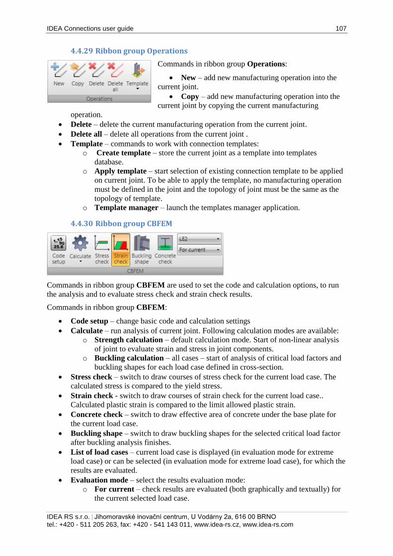
IDEA Connections user guide 107
IDEA RS s.r.o. | Jihomoravské inovační centrum, U Vodárny 2a, 616 00 BRNO
tel.: +420 - 511 205 263, fax: +420 - 541 143 011, www.idea-rs.cz, www.idea-rs.com
4.4.29 Ribbon group Operations
Commands in ribbon group Operations:
New – add new manufacturing operation into the
current joint.
Copy – add new manufacturing operation into the
current joint by copying the current manufacturing
operation.
Delete – delete the current manufacturing operation from the current joint.
Delete all – delete all operations from the current joint .
Template – commands to work with connection templates:
o Create template – store the current joint as a template into templates
database.
o Apply template – start selection of existing connection template to be applied
on current joint. To be able to apply the template, no manufacturing operation
must be defined in the joint and the topology of joint must be the same as the
topology of template.
o Template manager – launch the templates manager application.
4.4.30 Ribbon group CBFEM
Commands in ribbon group CBFEM are used to set the code and calculation options, to run
the analysis and to evaluate stress check and strain check results.
Commands in ribbon group CBFEM:
Code setup – change basic code and calculation settings
Calculate – run analysis of current joint. Following calculation modes are available:
o Strength calculation – default calculation mode. Start of non-linear analysis
of joint to evaluate strain and stress in joint components.
o Buckling calculation – all cases – start of analysis of critical load factors and
buckling shapes for each load case defined in cross-section.
Stress check – switch to draw courses of stress check for the current load case. The
calculated stress is compared to the yield stress.
Strain check - switch to draw courses of strain check for the current load case..
Calculated plastic strain is compared to the limit allowed plastic strain.
Concrete check – switch to draw effective area of concrete under the base plate for
the current load case.
Buckling shape – switch to draw buckling shapes for the selected critical load factor
after buckling analysis finishes.
List of load cases – current load case is displayed (in evaluation mode for extreme
load case) or can be selected (in evaluation mode for extreme load case), for which the
results are evaluated.
Evaluation mode – select the results evaluation mode:
o For current – check results are evaluated (both graphically and textually) for
the current selected load case.
IDEA Connections user guide 108
IDEA RS s.r.o. | Jihomoravské inovační centrum, U Vodárny 2a, 616 00 BRNO
tel.: +420 - 511 205 263, fax: +420 - 541 143 011, www.idea-rs.cz, www.idea-rs.com
o For extreme – load cases, which cause the extreme check value, are found for
each connection part. Results for such extreme cases are displayed in check
results tables. Graphically are results evaluated for load case corresponding to
the current row of check results table.
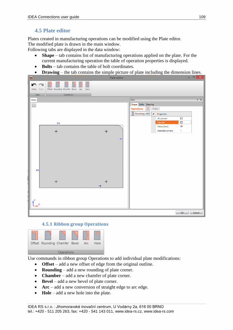
IDEA Connections user guide 109
IDEA RS s.r.o. | Jihomoravské inovační centrum, U Vodárny 2a, 616 00 BRNO
tel.: +420 - 511 205 263, fax: +420 - 541 143 011, www.idea-rs.cz, www.idea-rs.com
4.5 Plate editor
Plates created in manufacturing operations can be modified using the Plate editor.
The modified plate is drawn in the main window.
Following tabs are displayed in the data window:
Shape – tab contains list of manufacturing operations applied on the plate. For the
current manufacturing operation the table of operation properties is displayed.
Bolts – tab contains the table of bolt coordinates.
Drawing – the tab contains the simple picture of plate including the dimension lines.
4.5.1 Ribbon group Operations
Use commands in ribbon group Operations to add individual plate modifications:
Offset – add a new offset of edge from the original outline.
Rounding – add a new rounding of plate corner.
Chamber – add a new chamfer of plate corner.
Bevel – add a new bevel of plate corner.
Arc – add a new conversion of straight edge to arc edge.
Hole – add a new hole into the plate.
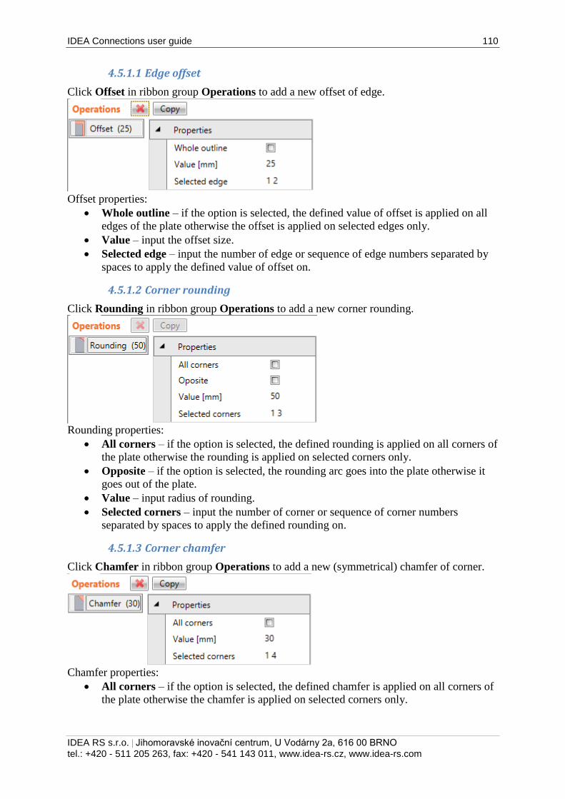
IDEA Connections user guide 110
IDEA RS s.r.o. | Jihomoravské inovační centrum, U Vodárny 2a, 616 00 BRNO
tel.: +420 - 511 205 263, fax: +420 - 541 143 011, www.idea-rs.cz, www.idea-rs.com
4.5.1.1 Edge offset
Click Offset in ribbon group Operations to add a new offset of edge.
Offset properties:
Whole outline – if the option is selected, the defined value of offset is applied on all
edges of the plate otherwise the offset is applied on selected edges only.
Value – input the offset size.
Selected edge – input the number of edge or sequence of edge numbers separated by
spaces to apply the defined value of offset on.
4.5.1.2 Corner rounding
Click Rounding in ribbon group Operations to add a new corner rounding.
Rounding properties:
All corners – if the option is selected, the defined rounding is applied on all corners of
the plate otherwise the rounding is applied on selected corners only.
Opposite – if the option is selected, the rounding arc goes into the plate otherwise it
goes out of the plate.
Value – input radius of rounding.
Selected corners – input the number of corner or sequence of corner numbers
separated by spaces to apply the defined rounding on.
4.5.1.3 Corner chamfer
Click Chamfer in ribbon group Operations to add a new (symmetrical) chamfer of corner.
Chamfer properties:
All corners – if the option is selected, the defined chamfer is applied on all corners of
the plate otherwise the chamfer is applied on selected corners only.
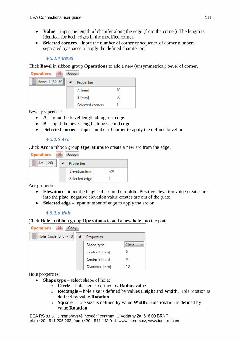
IDEA Connections user guide 111
IDEA RS s.r.o. | Jihomoravské inovační centrum, U Vodárny 2a, 616 00 BRNO
tel.: +420 - 511 205 263, fax: +420 - 541 143 011, www.idea-rs.cz, www.idea-rs.com
Value – input the length of chamfer along the edge (from the corner). The length is
identical for both edges in the modified corner.
Selected corners – input the number of corner or sequence of corner numbers
separated by spaces to apply the defined chamfer on.
4.5.1.4 Bevel
Click Bevel in ribbon group Operations to add a new (unsymmetrical) bevel of corner.
Bevel properties:
A – input the bevel length along one edge.
B – input the bevel length along second edge.
Selected corner – input number of corner to apply the defined bevel on.
4.5.1.5 Arc
Click Arc in ribbon group Operations to create a new arc from the edge.
Arc properties:
Elevation – input the height of arc in the middle. Positive elevation value creates arc
into the plate, negative elevation value creates arc out of the plate.
Selected edge – input number of edge to apply the arc on.
4.5.1.6 Hole
Click Hole in ribbon group Operations to add a new hole into the plate.
Hole properties:
Shape type – select shape of hole:
o Circle – hole size is defined by Radius value.
o Rectangle – hole size is defined by values Height and Width. Hole rotation is
defined by value Rotation.
o Square – hole size is defined by value Width. Hole rotation is defined by
value Rotation.

IDEA Connections user guide 112
IDEA RS s.r.o. | Jihomoravské inovační centrum, U Vodárny 2a, 616 00 BRNO
tel.: +420 - 511 205 263, fax: +420 - 541 143 011, www.idea-rs.cz, www.idea-rs.com
Centre X – x-coordinate of hole centre.
Centre Y - y-coordinate of hole centre.
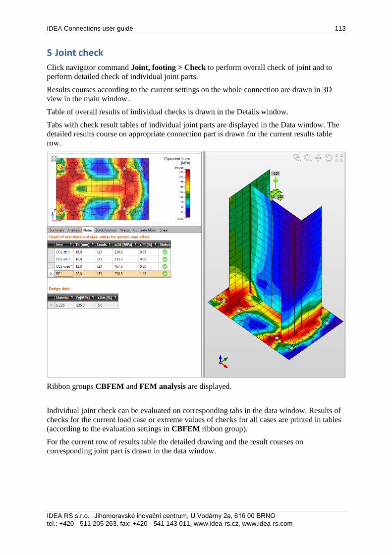
IDEA Connections user guide 113
IDEA RS s.r.o. | Jihomoravské inovační centrum, U Vodárny 2a, 616 00 BRNO
tel.: +420 - 511 205 263, fax: +420 - 541 143 011, www.idea-rs.cz, www.idea-rs.com
5 Joint check
Click navigator command Joint, footing > Check to perform overall check of joint and to
perform detailed check of individual joint parts.
Results courses according to the current settings on the whole connection are drawn in 3D
view in the main window..
Table of overall results of individual checks is drawn in the Details window.
Tabs with check result tables of individual joint parts are displayed in the Data window. The
detailed results course on appropriate connection part is drawn for the current results table
row.
Ribbon groups CBFEM and FEM analysis are displayed.
Individual joint check can be evaluated on corresponding tabs in the data window. Results of
checks for the current load case or extreme values of checks for all cases are printed in tables
(according to the evaluation settings in CBFEM ribbon group).
For the current row of results table the detailed drawing and the result courses on
corresponding joint part is drawn in the data window.
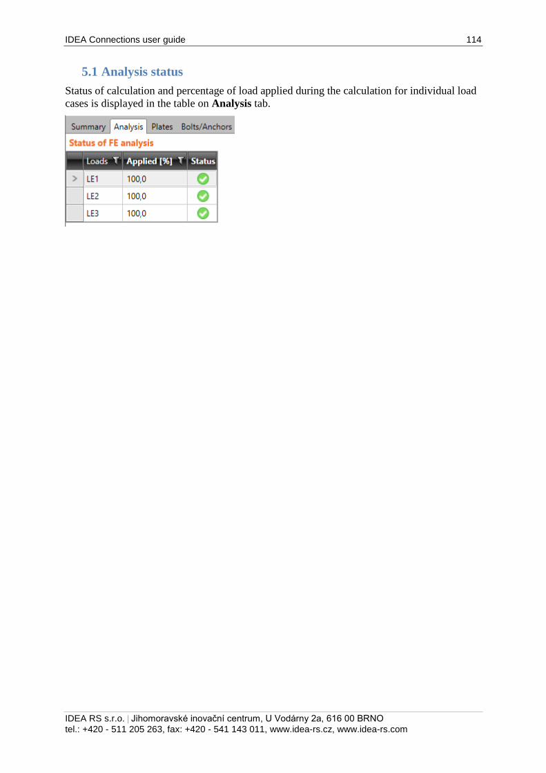
IDEA Connections user guide 114
IDEA RS s.r.o. | Jihomoravské inovační centrum, U Vodárny 2a, 616 00 BRNO
tel.: +420 - 511 205 263, fax: +420 - 541 143 011, www.idea-rs.cz, www.idea-rs.com
5.1 Analysis status
Status of calculation and percentage of load applied during the calculation for individual load
cases is displayed in the table on Analysis tab.
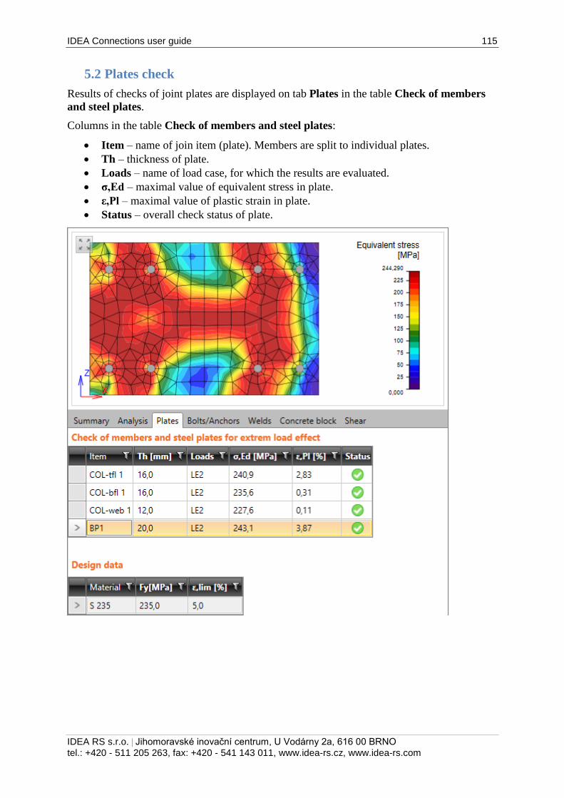
IDEA Connections user guide 115
IDEA RS s.r.o. | Jihomoravské inovační centrum, U Vodárny 2a, 616 00 BRNO
tel.: +420 - 511 205 263, fax: +420 - 541 143 011, www.idea-rs.cz, www.idea-rs.com
5.2 Plates check
Results of checks of joint plates are displayed on tab Plates in the table Check of members
and steel plates.
Columns in the table Check of members and steel plates:
Item – name of join item (plate). Members are split to individual plates.
Th – thickness of plate.
Loads – name of load case, for which the results are evaluated.
σ,Ed – maximal value of equivalent stress in plate.
ε,Pl – maximal value of plastic strain in plate.
Status – overall check status of plate.
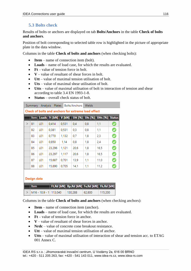
IDEA Connections user guide 116
IDEA RS s.r.o. | Jihomoravské inovační centrum, U Vodárny 2a, 616 00 BRNO
tel.: +420 - 511 205 263, fax: +420 - 541 143 011, www.idea-rs.cz, www.idea-rs.com
5.3 Bolts check
Results of bolts or anchors are displayed on tab Bolts/Anchors in the table Check of bolts
and anchors.
Position of bolt corresponding to selected table row is highlighted in the picture of appropriate
plate in the data window.
Columns in the table Check of bolts and anchors (when checking bolts):
Item – name of connection item (bolt).
Loads – name of load case, for which the results are evaluated.
Ft – value of tension force in bolt.
V – value of resultant of shear forces in bolt.
Utt – value of maximal tension utilisation of bolt.
Uts – value of maximal shear utilisation of bolt.
Utts – value of maximal utilisation of bolt in interaction of tension and shear
according to table 3.4 EN 1993-1-8.
Status – overall check status of bolt.
Columns in the table Check of bolts and anchors (when checking anchors):
Item – name of connection item (anchor).
Loads – name of load case, for which the results are evaluated.
Ft – value of tension force in anchor.
V – value of resultant of shear forces in anchor.
Nrdc – value of concrete cone breakout resistance.
Utt – value of maximal tension utilisation of anchor.
Utts – value of maximal utilisation of interaction of shear and tension acc. to ETAG
001 Annex C.
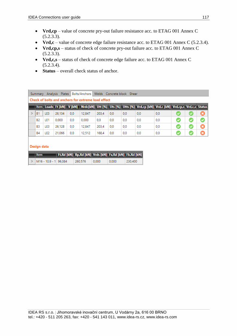
IDEA Connections user guide 117
IDEA RS s.r.o. | Jihomoravské inovační centrum, U Vodárny 2a, 616 00 BRNO
tel.: +420 - 511 205 263, fax: +420 - 541 143 011, www.idea-rs.cz, www.idea-rs.com
Vrd,cp – value of concrete pry-out failure resistance acc. to ETAG 001 Annex C
(5.2.3.3).
Vrd,c – value of concrete edge failure resistance acc. to ETAG 001 Annex C (5.2.3.4).
Vrd,cp,s – status of check of concrete pry-out failure acc. to ETAG 001 Annex C
(5.2.3.3).
Vrd,c,s – status of check of concrete edge failure acc. to ETAG 001 Annex C
(5.2.3.4).
Status – overall check status of anchor.
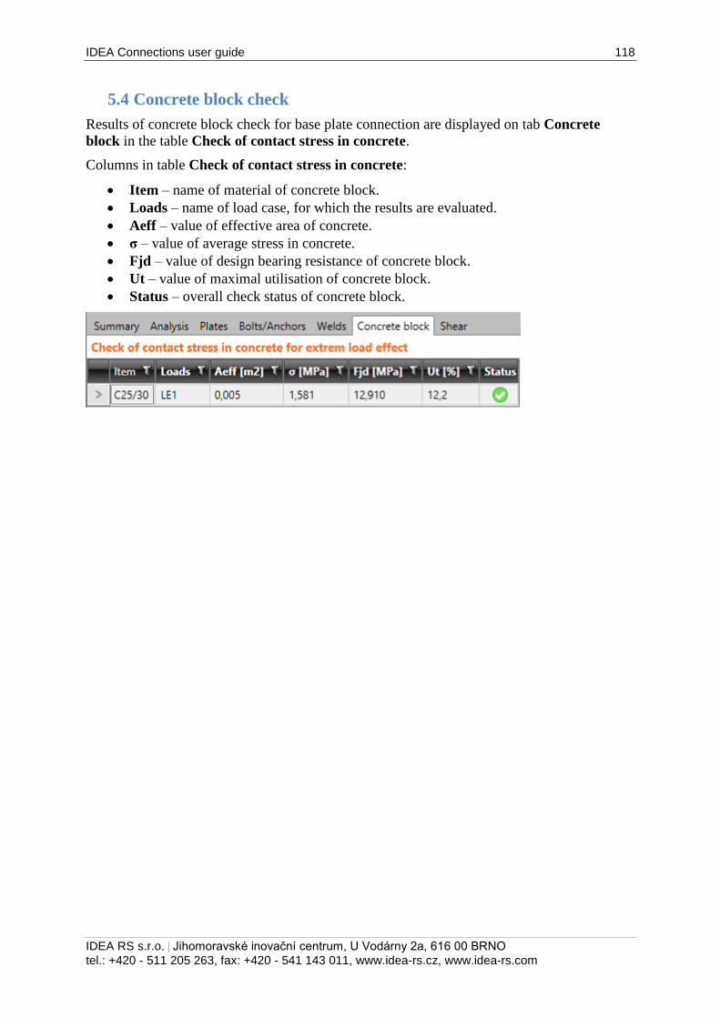
IDEA Connections user guide 118
IDEA RS s.r.o. | Jihomoravské inovační centrum, U Vodárny 2a, 616 00 BRNO
tel.: +420 - 511 205 263, fax: +420 - 541 143 011, www.idea-rs.cz, www.idea-rs.com
5.4 Concrete block check
Results of concrete block check for base plate connection are displayed on tab Concrete
block in the table Check of contact stress in concrete.
Columns in table Check of contact stress in concrete:
Item – name of material of concrete block.
Loads – name of load case, for which the results are evaluated.
Aeff – value of effective area of concrete.
σ – value of average stress in concrete.
Fjd – value of design bearing resistance of concrete block.
Ut – value of maximal utilisation of concrete block.
Status – overall check status of concrete block.
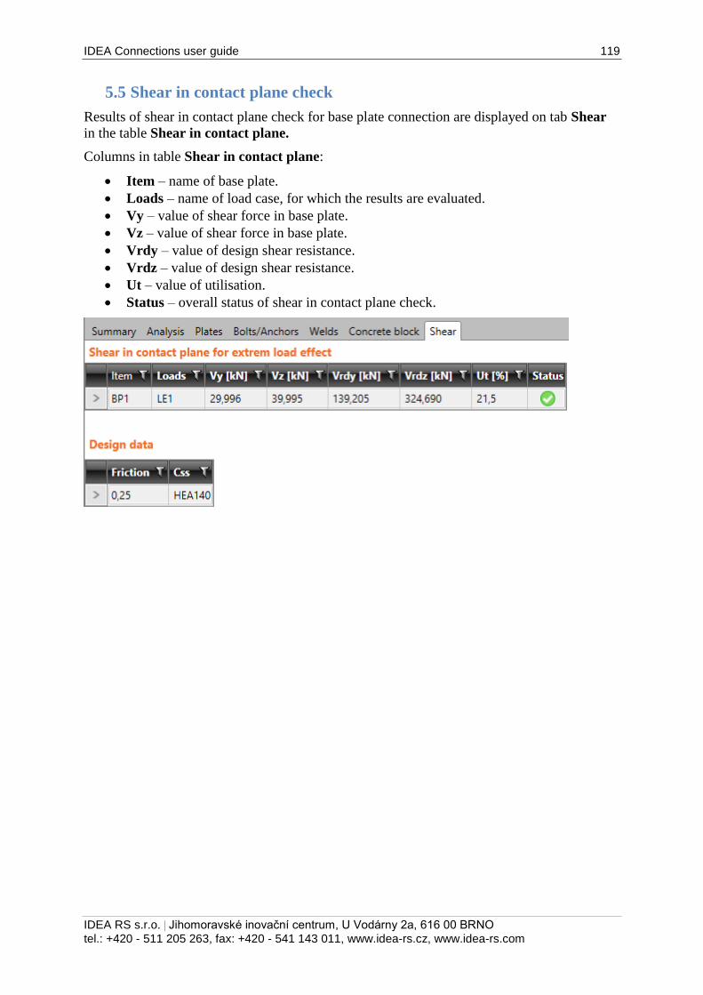
IDEA Connections user guide 119
IDEA RS s.r.o. | Jihomoravské inovační centrum, U Vodárny 2a, 616 00 BRNO
tel.: +420 - 511 205 263, fax: +420 - 541 143 011, www.idea-rs.cz, www.idea-rs.com
5.5 Shear in contact plane check
Results of shear in contact plane check for base plate connection are displayed on tab Shear
in the table Shear in contact plane.
Columns in table Shear in contact plane:
Item – name of base plate.
Loads – name of load case, for which the results are evaluated.
Vy – value of shear force in base plate.
Vz – value of shear force in base plate.
Vrdy – value of design shear resistance.
Vrdz – value of design shear resistance.
Ut – value of utilisation.
Status – overall status of shear in contact plane check.
IDEA Connections user guide 120
IDEA RS s.r.o. | Jihomoravské inovační centrum, U Vodárny 2a, 616 00 BRNO
tel.: +420 - 511 205 263, fax: +420 - 541 143 011, www.idea-rs.cz, www.idea-rs.com
5.6 Welds check
Results of welds check are displayed on tab Welds in the table Check of welds.
Weld corresponding to current table row is highlighted in the picture of appropriate plate in
the data window.
Columns in table Check of welds:
Item – name of weld.
Edge – generated name of edge, to which the weld is related.
Th. – value of throat thickness of weld.
L – length of weld.
Type – type of weld.
Loads – name of load case, for which the results are evaluated.
σw,Ed –value of equivalent stress in weld.
σ┴ - value of stress perpendicular to weld throat.
τ|| - shear stress parallel to the weld axis.
τ┴ - shear stress perpendicular to the weld axis.
Ut – value of maximal weld utilisation.
Status – overall check status of weld.
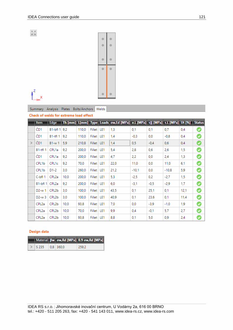
IDEA Connections user guide 121
IDEA RS s.r.o. | Jihomoravské inovační centrum, U Vodárny 2a, 616 00 BRNO
tel.: +420 - 511 205 263, fax: +420 - 541 143 011, www.idea-rs.cz, www.idea-rs.com
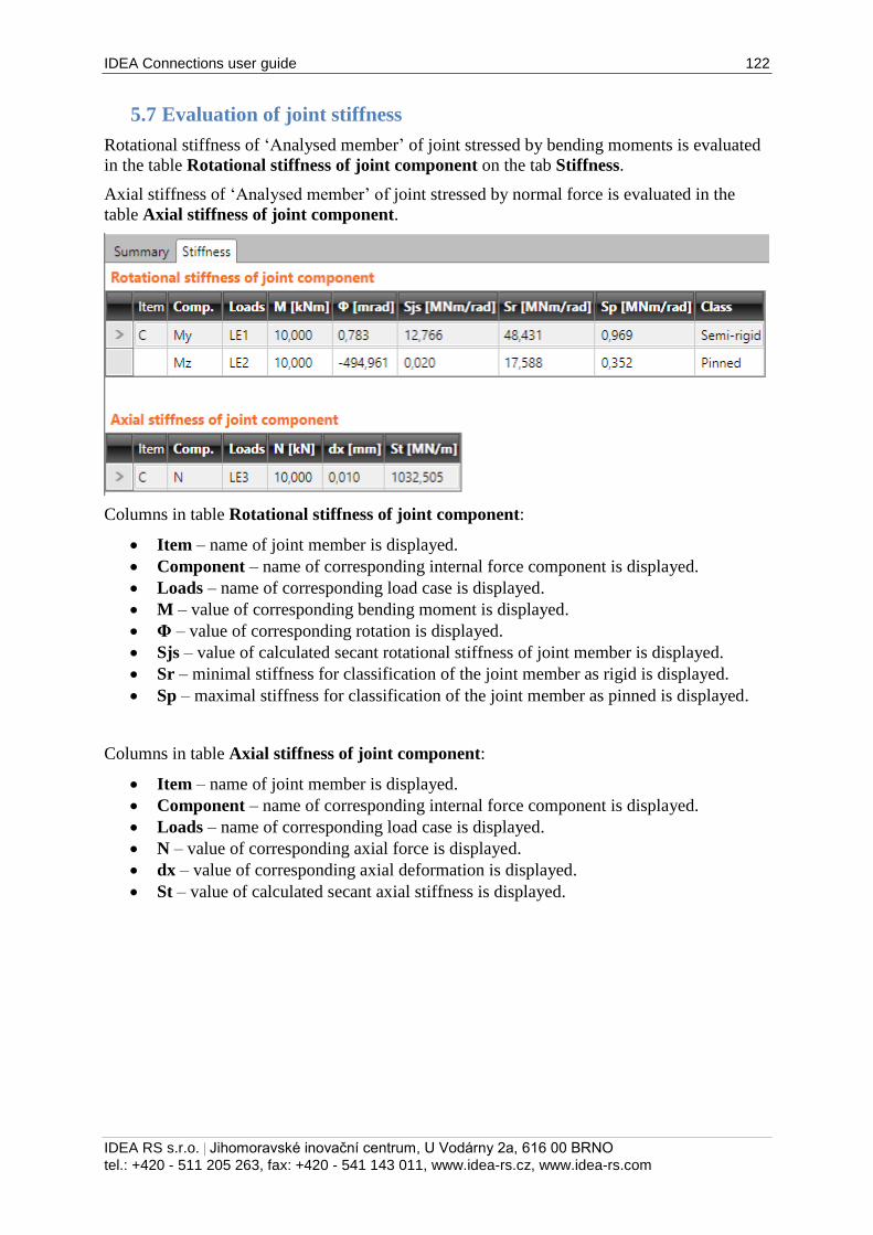
IDEA Connections user guide 122
IDEA RS s.r.o. | Jihomoravské inovační centrum, U Vodárny 2a, 616 00 BRNO
tel.: +420 - 511 205 263, fax: +420 - 541 143 011, www.idea-rs.cz, www.idea-rs.com
5.7 Evaluation of joint stiffness
Rotational stiffness of ‘Analysed member’ of joint stressed by bending moments is evaluated
in the table Rotational stiffness of joint component on the tab Stiffness.
Axial stiffness of ‘Analysed member’ of joint stressed by normal force is evaluated in the
table Axial stiffness of joint component.
Columns in table Rotational stiffness of joint component:
Item – name of joint member is displayed.
Component – name of corresponding internal force component is displayed.
Loads – name of corresponding load case is displayed.
M – value of corresponding bending moment is displayed.
Φ – value of corresponding rotation is displayed.
Sjs – value of calculated secant rotational stiffness of joint member is displayed.
Sr – minimal stiffness for classification of the joint member as rigid is displayed.
Sp – maximal stiffness for classification of the joint member as pinned is displayed.
Columns in table Axial stiffness of joint component:
Item – name of joint member is displayed.
Component – name of corresponding internal force component is displayed.
Loads – name of corresponding load case is displayed.
N – value of corresponding axial force is displayed.
dx – value of corresponding axial deformation is displayed.
St – value of calculated secant axial stiffness is displayed.
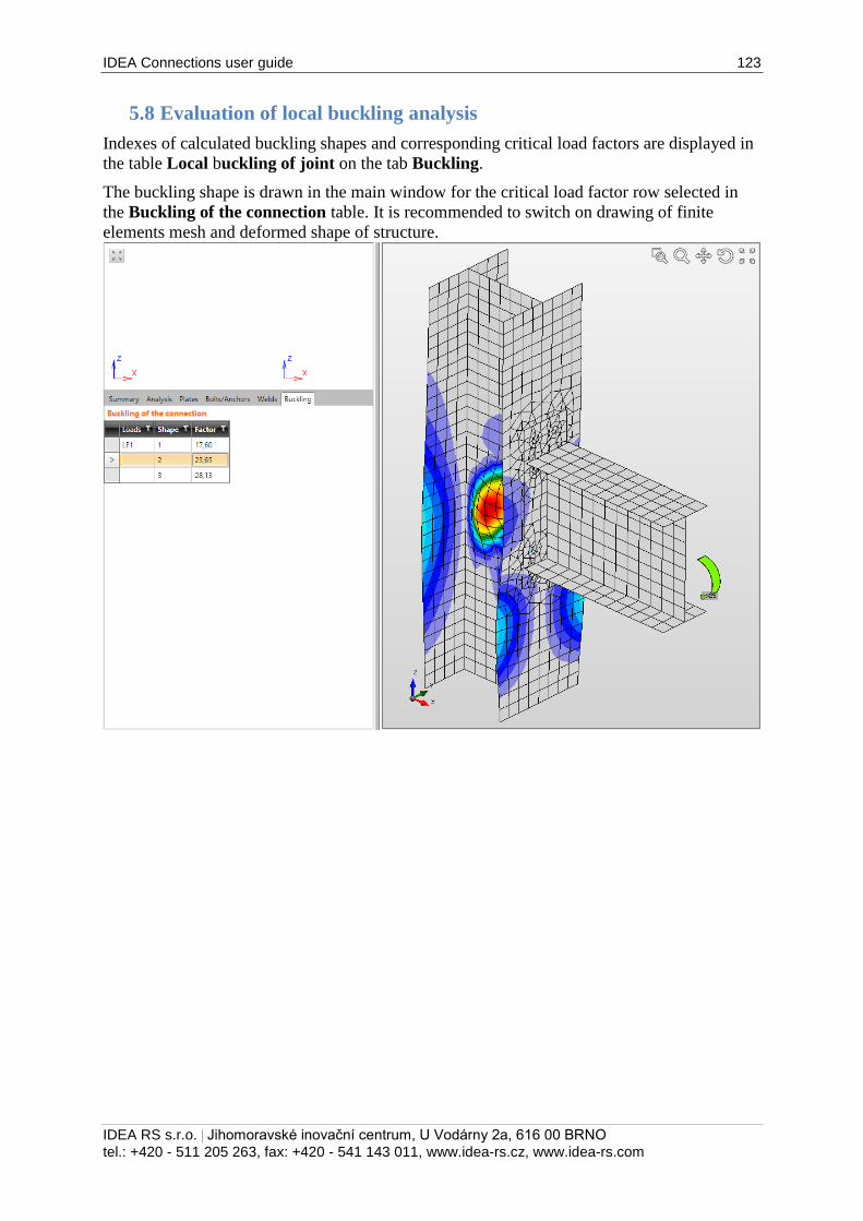
IDEA Connections user guide 123
IDEA RS s.r.o. | Jihomoravské inovační centrum, U Vodárny 2a, 616 00 BRNO
tel.: +420 - 511 205 263, fax: +420 - 541 143 011, www.idea-rs.cz, www.idea-rs.com
5.8 Evaluation of local buckling analysis
Indexes of calculated buckling shapes and corresponding critical load factors are displayed in
the table Local buckling of joint on the tab Buckling.
The buckling shape is drawn in the main window for the critical load factor row selected in
the Buckling of the connection table. It is recommended to switch on drawing of finite
elements mesh and deformed shape of structure.
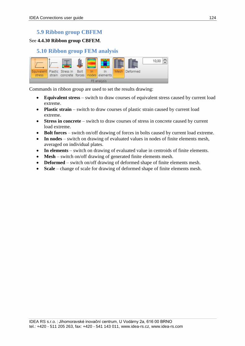
IDEA Connections user guide 124
IDEA RS s.r.o. | Jihomoravské inovační centrum, U Vodárny 2a, 616 00 BRNO
tel.: +420 - 511 205 263, fax: +420 - 541 143 011, www.idea-rs.cz, www.idea-rs.com
5.9 Ribbon group CBFEM
See 4.4.30 Ribbon group CBFEM.
5.10 Ribbon group FEM analysis
Commands in ribbon group are used to set the results drawing:
Equivalent stress – switch to draw courses of equivalent stress caused by current load
extreme.
Plastic strain – switch to draw courses of plastic strain caused by current load
extreme.
Stress in concrete – switch to draw courses of stress in concrete caused by current
load extreme.
Bolt forces – switch on/off drawing of forces in bolts caused by current load extreme.
In nodes – switch on drawing of evaluated values in nodes of finite elements mesh,
averaged on individual plates.
In elements – switch on drawing of evaluated value in centroids of finite elements.
Mesh – switch on/off drawing of generated finite elements mesh.
Deformed – switch on/off drawing of deformed shape of finite elements mesh.
Scale – change of scale for drawing of deformed shape of finite elements mesh.
IDEA Connections user guide 125
IDEA RS s.r.o. | Jihomoravské inovační centrum, U Vodárny 2a, 616 00 BRNO
tel.: +420 - 511 205 263, fax: +420 - 541 143 011, www.idea-rs.cz, www.idea-rs.com
5.11 Report of current joint check
Click navigator item Joint, footing > Results to generate check report of the current joint.
The content of report can be changed in data window – see 6.5 Detailed report.
The generated check report is displayed in the main window.
Ribbon group Report view is displayed.
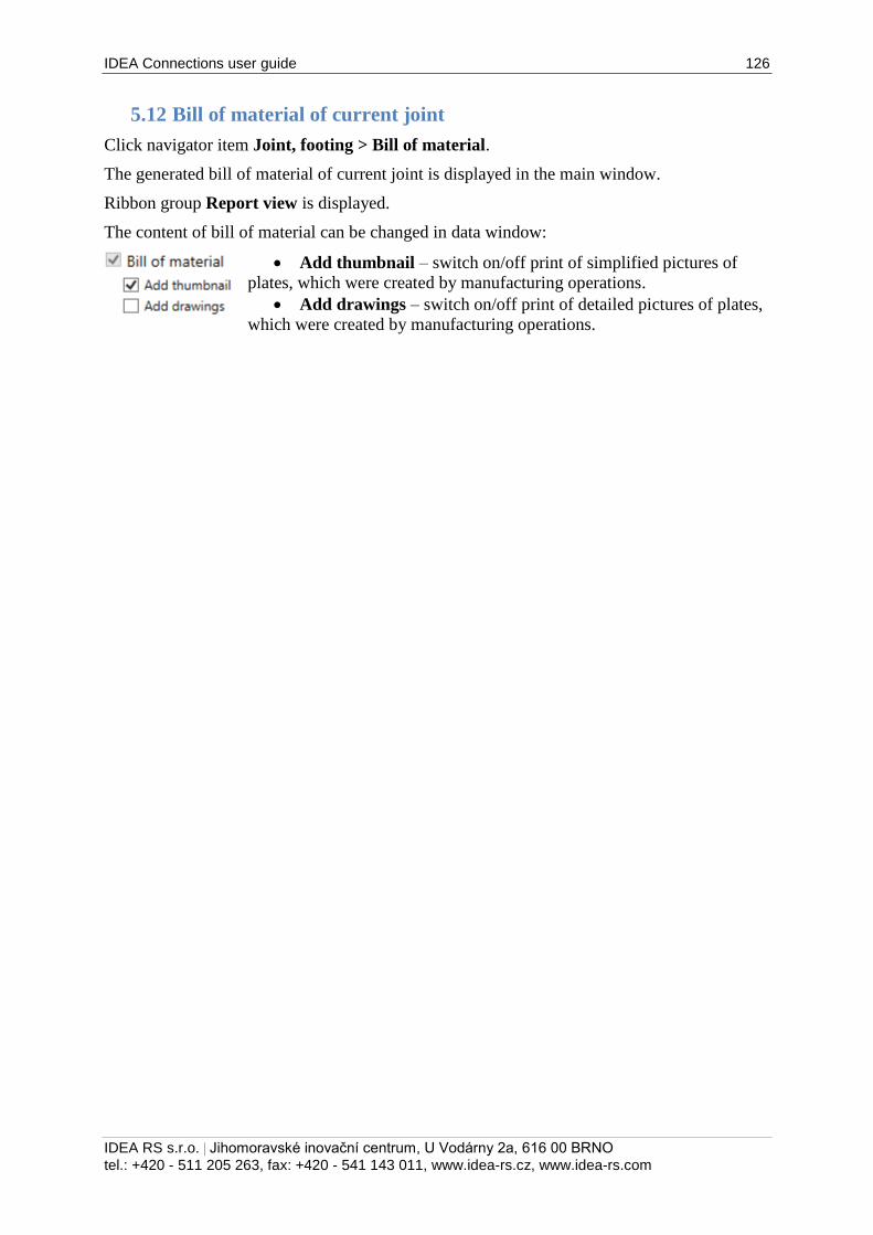
IDEA Connections user guide 126
IDEA RS s.r.o. | Jihomoravské inovační centrum, U Vodárny 2a, 616 00 BRNO
tel.: +420 - 511 205 263, fax: +420 - 541 143 011, www.idea-rs.cz, www.idea-rs.com
5.12 Bill of material of current joint
Click navigator item Joint, footing > Bill of material.
The generated bill of material of current joint is displayed in the main window.
Ribbon group Report view is displayed.
The content of bill of material can be changed in data window:
Add thumbnail – switch on/off print of simplified pictures of
plates, which were created by manufacturing operations.
Add drawings – switch on/off print of detailed pictures of plates,
which were created by manufacturing operations.
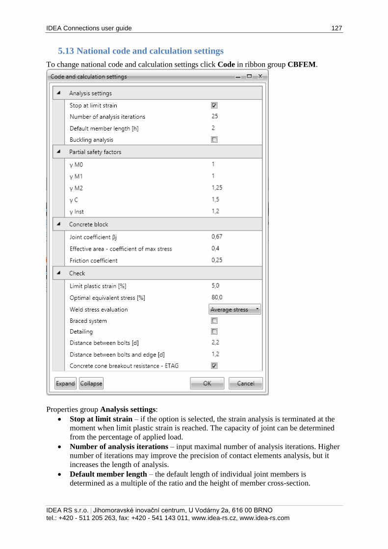
IDEA Connections user guide 127
IDEA RS s.r.o. | Jihomoravské inovační centrum, U Vodárny 2a, 616 00 BRNO
tel.: +420 - 511 205 263, fax: +420 - 541 143 011, www.idea-rs.cz, www.idea-rs.com
5.13 National code and calculation settings
To change national code and calculation settings click Code in ribbon group CBFEM.
Properties group Analysis settings:
Stop at limit strain – if the option is selected, the strain analysis is terminated at the
moment when limit plastic strain is reached. The capacity of joint can be determined
from the percentage of applied load.
Number of analysis iterations – input maximal number of analysis iterations. Higher
number of iterations may improve the precision of contact elements analysis, but it
increases the length of analysis.
Default member length – the default length of individual joint members is
determined as a multiple of the ratio and the height of member cross-section.
IDEA Connections user guide 128
IDEA RS s.r.o. | Jihomoravské inovační centrum, U Vodárny 2a, 616 00 BRNO
tel.: +420 - 511 205 263, fax: +420 - 541 143 011, www.idea-rs.cz, www.idea-rs.com
Buckling analysis – if the option is selected, the analysis of local buckling of joint can
be performed to determine critical load factors and buckling shapes.
Properties group Partial safety factors:
γ M0 – partial factor for resistance of cross-section.
γ M1 – partial safety factor for resistance of members.
γ M2 – partial safety factor for resistance of bolts, rivets, pins, welds, plates in
bearing.
γ C – partial safety factor for resistance of concrete.
γ Inst – partial safety factor for installation safety.
Properties group Concrete block:
Joint coefficient βj – input value of coefficient to determine the design bearing
strength of concrete Fjd.
Effective area – coeff of maximal stress – input value of maximal stress coefficient
to determine the effective area of concrete. The effective area is determined from the
area, where stress is higher than the multiple of defined coefficient and maximal
stress.
Friction coefficient – input value of friction coefficient between the base plate and the
concrete block.
Properties group Check:
Limit plastic strain – value of allowed limit plastic strain. The joint does not satisfy if
the limit plastic strain is exceeded.
Optimal equivalent stress – lower limit of optimal range of equivalent stress (drawn
using green color) as the percentage of yield stress.
Weld stress evaluation – select method for evaluation of stress in welds:
o Maximal stress – the weld stress value is determined as the maximal value of
stress along the weld.
o Average stress – the weld stress value is determined as average stress along
the weld.
o Linear interpolation – the weld stress value is determined using linear
interpolation method.
Braced system – if selected, the structural system is considered as braced during
calculation of joint stiffness.
Detailing – switch on/off check of detailing provisions.
Distance between bolts – input the multiple of bolt diameter to determine the allowed
distance between bolts.
Distance between bolts and edge – input the multiple of bolt diameter to determine
the minimal allowed distance between bolt and plate edge.
Concrete cone breakout resistance – ETAG – switch on/off check of concrete cone
breakout resistance.
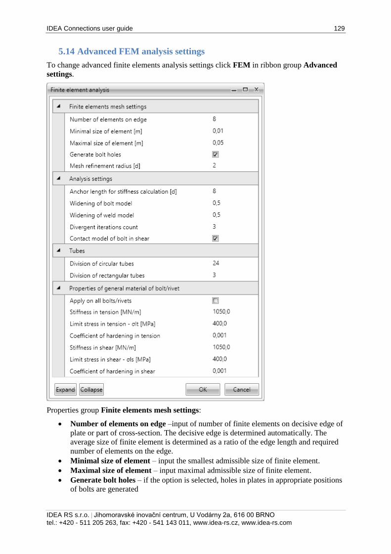
IDEA Connections user guide 129
IDEA RS s.r.o. | Jihomoravské inovační centrum, U Vodárny 2a, 616 00 BRNO
tel.: +420 - 511 205 263, fax: +420 - 541 143 011, www.idea-rs.cz, www.idea-rs.com
5.14 Advanced FEM analysis settings
To change advanced finite elements analysis settings click FEM in ribbon group Advanced
settings.
Properties group Finite elements mesh settings:
Number of elements on edge –input of number of finite elements on decisive edge of
plate or part of cross-section. The decisive edge is determined automatically. The
average size of finite element is determined as a ratio of the edge length and required
number of elements on the edge.
Minimal size of element – input the smallest admissible size of finite element.
Maximal size of element – input maximal admissible size of finite element.
Generate bolt holes – if the option is selected, holes in plates in appropriate positions
of bolts are generated
IDEA Connections user guide 130
IDEA RS s.r.o. | Jihomoravské inovační centrum, U Vodárny 2a, 616 00 BRNO
tel.: +420 - 511 205 263, fax: +420 - 541 143 011, www.idea-rs.cz, www.idea-rs.com
Mesh refinement radius [d] – input radius of circular area around the bolt, where the
mesh is refined, as the multiple of bolt diameter.
Properties group Analysis settings:
Anchor length for stiffness calculation [d] – input of length of spring modelling the
anchor in stiffness analysis, as the multiple of anchor diameter.
Widening of bolt model – input of width increase of interpolation constraint, which is
modelling the bolt, as the multiple of plate thickness.
Widening of weld model – input of width increase of interpolation constraint, which
is modelling the weld, as the multiple of plate thickness.
Divergent iterations count – input the admissible number of divergent iterations.
Contact model of bolt in shear – if the option is selected, bolts in shear are modelled
using contact elements taking effect only in compressed area of bolt hole.
Properties group Tubes:
Division of circular tubes – input number of straight lines substituting the circle of
circular tubes.
Division of rectangular tubes – input number of straight lines substituting the arc in
edge of rectangular tubes.
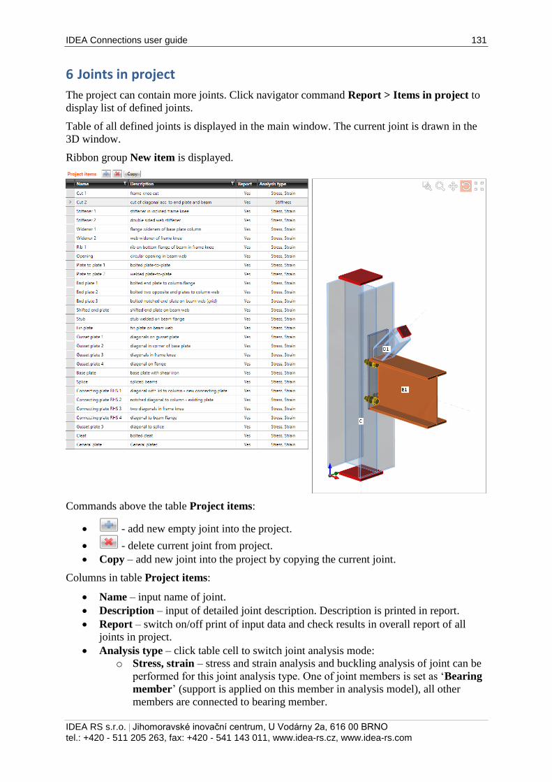
IDEA Connections user guide 131
IDEA RS s.r.o. | Jihomoravské inovační centrum, U Vodárny 2a, 616 00 BRNO
tel.: +420 - 511 205 263, fax: +420 - 541 143 011, www.idea-rs.cz, www.idea-rs.com
6 Joints in project
The project can contain more joints. Click navigator command Report > Items in project to
display list of defined joints.
Table of all defined joints is displayed in the main window. The current joint is drawn in the
3D window.
Ribbon group New item is displayed.
Commands above the table Project items:
- add new empty joint into the project.
- delete current joint from project.
Copy – add new joint into the project by copying the current joint.
Columns in table Project items:
Name – input name of joint.
Description – input of detailed joint description. Description is printed in report.
Report – switch on/off print of input data and check results in overall report of all
joints in project.
Analysis type – click table cell to switch joint analysis mode:
o Stress, strain – stress and strain analysis and buckling analysis of joint can be
performed for this joint analysis type. One of joint members is set as ‘Bearing
member’ (support is applied on this member in analysis model), all other
members are connected to bearing member.
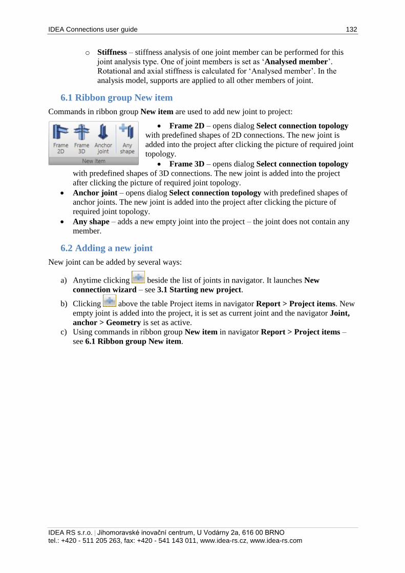
IDEA Connections user guide 132
IDEA RS s.r.o. | Jihomoravské inovační centrum, U Vodárny 2a, 616 00 BRNO
tel.: +420 - 511 205 263, fax: +420 - 541 143 011, www.idea-rs.cz, www.idea-rs.com
o Stiffness – stiffness analysis of one joint member can be performed for this
joint analysis type. One of joint members is set as ‘Analysed member’.
Rotational and axial stiffness is calculated for ‘Analysed member’. In the
analysis model, supports are applied to all other members of joint.
6.1 Ribbon group New item
Commands in ribbon group New item are used to add new joint to project:
Frame 2D – opens dialog Select connection topology
with predefined shapes of 2D connections. The new joint is
added into the project after clicking the picture of required joint
topology.
Frame 3D – opens dialog Select connection topology
with predefined shapes of 3D connections. The new joint is added into the project
after clicking the picture of required joint topology.
Anchor joint – opens dialog Select connection topology with predefined shapes of
anchor joints. The new joint is added into the project after clicking the picture of
required joint topology.
Any shape – adds a new empty joint into the project – the joint does not contain any
member.
6.2 Adding a new joint
New joint can be added by several ways:
a) Anytime clicking beside the list of joints in navigator. It launches New
connection wizard – see 3.1 Starting new project.
b) Clicking above the table Project items in navigator Report > Project items. New
empty joint is added into the project, it is set as current joint and the navigator Joint,
anchor > Geometry is set as active.
c) Using commands in ribbon group New item in navigator Report > Project items –
see 6.1 Ribbon group New item.
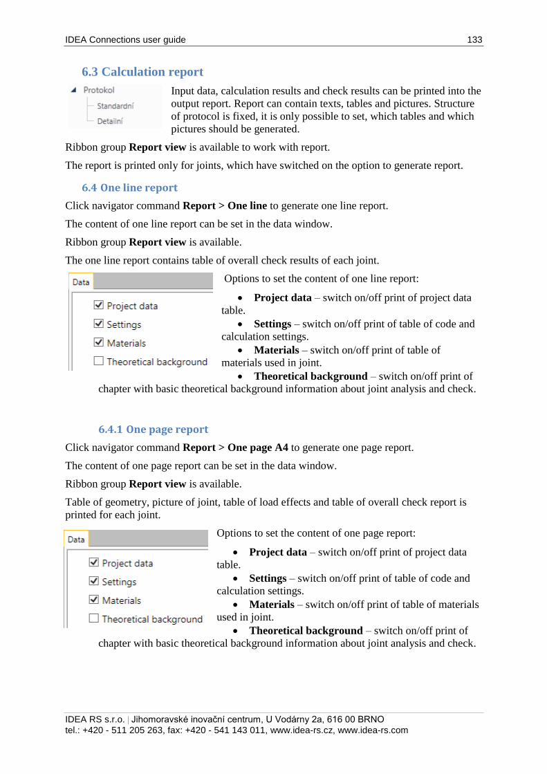
IDEA Connections user guide 133
IDEA RS s.r.o. | Jihomoravské inovační centrum, U Vodárny 2a, 616 00 BRNO
tel.: +420 - 511 205 263, fax: +420 - 541 143 011, www.idea-rs.cz, www.idea-rs.com
6.3 Calculation report
Input data, calculation results and check results can be printed into the
output report. Report can contain texts, tables and pictures. Structure
of protocol is fixed, it is only possible to set, which tables and which
pictures should be generated.
Ribbon group Report view is available to work with report.
The report is printed only for joints, which have switched on the option to generate report.
6.4 One line report
Click navigator command Report > One line to generate one line report.
The content of one line report can be set in the data window.
Ribbon group Report view is available.
The one line report contains table of overall check results of each joint.
Options to set the content of one line report:
Project data – switch on/off print of project data
table.
Settings – switch on/off print of table of code and
calculation settings.
Materials – switch on/off print of table of
materials used in joint.
Theoretical background – switch on/off print of
chapter with basic theoretical background information about joint analysis and check.
6.4.1 One page report
Click navigator command Report > One page A4 to generate one page report.
The content of one page report can be set in the data window.
Ribbon group Report view is available.
Table of geometry, picture of joint, table of load effects and table of overall check report is
printed for each joint.
Options to set the content of one page report:
Project data – switch on/off print of project data
table.
Settings – switch on/off print of table of code and
calculation settings.
Materials – switch on/off print of table of materials
used in joint.
Theoretical background – switch on/off print of
chapter with basic theoretical background information about joint analysis and check.
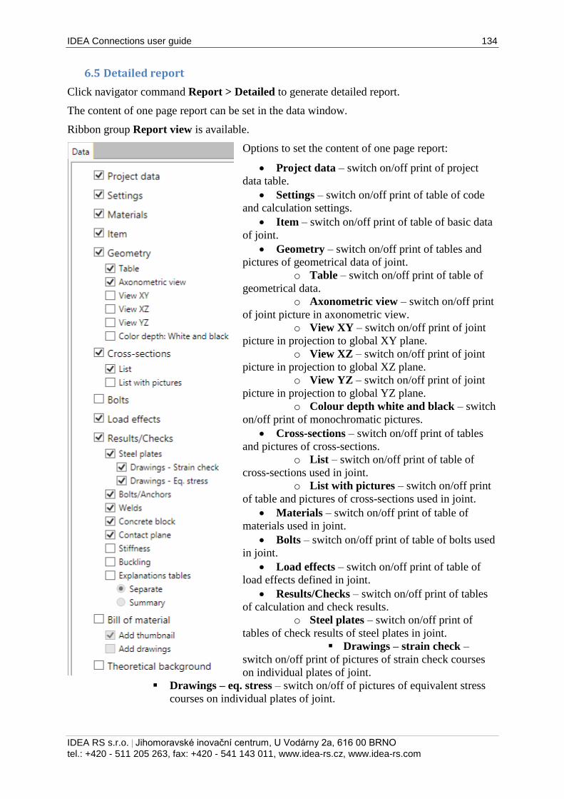
IDEA Connections user guide 134
IDEA RS s.r.o. | Jihomoravské inovační centrum, U Vodárny 2a, 616 00 BRNO
tel.: +420 - 511 205 263, fax: +420 - 541 143 011, www.idea-rs.cz, www.idea-rs.com
6.5 Detailed report
Click navigator command Report > Detailed to generate detailed report.
The content of one page report can be set in the data window.
Ribbon group Report view is available.
Options to set the content of one page report:
Project data – switch on/off print of project
data table.
Settings – switch on/off print of table of code
and calculation settings.
Item – switch on/off print of table of basic data
of joint.
Geometry – switch on/off print of tables and
pictures of geometrical data of joint.
o Table – switch on/off print of table of
geometrical data.
o Axonometric view – switch on/off print
of joint picture in axonometric view.
o View XY – switch on/off print of joint
picture in projection to global XY plane.
o View XZ – switch on/off print of joint
picture in projection to global XZ plane.
o View YZ – switch on/off print of joint
picture in projection to global YZ plane.
o Colour depth white and black – switch
on/off print of monochromatic pictures.
Cross-sections – switch on/off print of tables
and pictures of cross-sections.
o List – switch on/off print of table of
cross-sections used in joint.
o List with pictures – switch on/off print
of table and pictures of cross-sections used in joint.
Materials – switch on/off print of table of
materials used in joint.
Bolts – switch on/off print of table of bolts used
in joint.
Load effects – switch on/off print of table of
load effects defined in joint.
Results/Checks – switch on/off print of tables
of calculation and check results.
o Steel plates – switch on/off print of
tables of check results of steel plates in joint.
Drawings – strain check –
switch on/off print of pictures of strain check courses
on individual plates of joint.
Drawings – eq. stress – switch on/off of pictures of equivalent stress
courses on individual plates of joint.
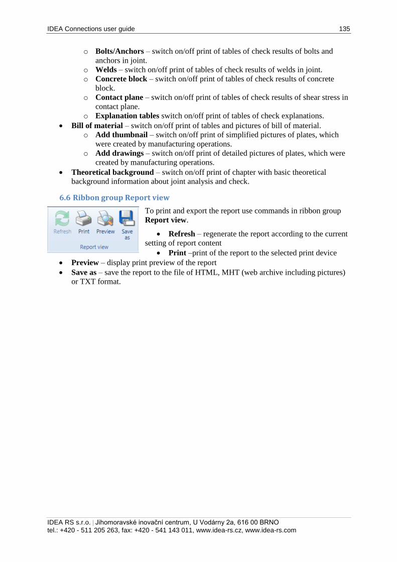
IDEA Connections user guide 135
IDEA RS s.r.o. | Jihomoravské inovační centrum, U Vodárny 2a, 616 00 BRNO
tel.: +420 - 511 205 263, fax: +420 - 541 143 011, www.idea-rs.cz, www.idea-rs.com
o Bolts/Anchors – switch on/off print of tables of check results of bolts and
anchors in joint.
o Welds – switch on/off print of tables of check results of welds in joint.
o Concrete block – switch on/off print of tables of check results of concrete
block.
o Contact plane – switch on/off print of tables of check results of shear stress in
contact plane.
o Explanation tables switch on/off print of tables of check explanations.
Bill of material – switch on/off print of tables and pictures of bill of material.
o Add thumbnail – switch on/off print of simplified pictures of plates, which
were created by manufacturing operations.
o Add drawings – switch on/off print of detailed pictures of plates, which were
created by manufacturing operations.
Theoretical background – switch on/off print of chapter with basic theoretical
background information about joint analysis and check.
6.6 Ribbon group Report view
To print and export the report use commands in ribbon group
Report view.
Refresh – regenerate the report according to the current
setting of report content
Print –print of the report to the selected print device
Preview – display print preview of the report
Save as – save the report to the file of HTML, MHT (web archive including pictures)
or TXT format.
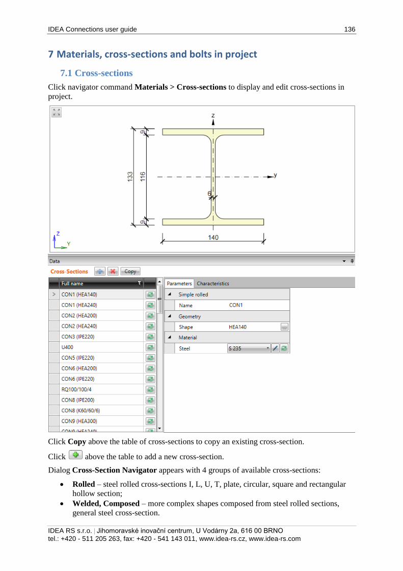
IDEA Connections user guide 136
IDEA RS s.r.o. | Jihomoravské inovační centrum, U Vodárny 2a, 616 00 BRNO
tel.: +420 - 511 205 263, fax: +420 - 541 143 011, www.idea-rs.cz, www.idea-rs.com
7 Materials, cross-sections and bolts in project
7.1 Cross-sections
Click navigator command Materials > Cross-sections to display and edit cross-sections in
project.
Click Copy above the table of cross-sections to copy an existing cross-section.
Click above the table to add a new cross-section.
Dialog Cross-Section Navigator appears with 4 groups of available cross-sections:
Rolled – steel rolled cross-sections I, L, U, T, plate, circular, square and rectangular
hollow section;
Welded, Composed – more complex shapes composed from steel rolled sections,
general steel cross-section.
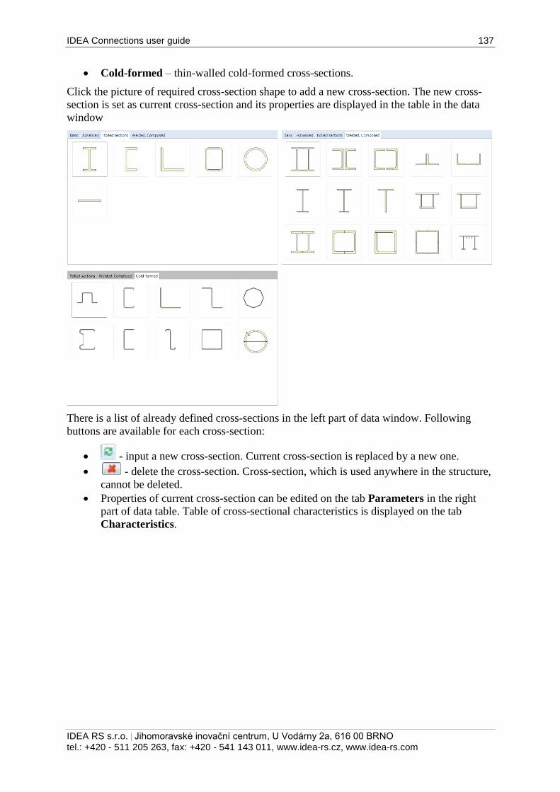
IDEA Connections user guide 137
IDEA RS s.r.o. | Jihomoravské inovační centrum, U Vodárny 2a, 616 00 BRNO
tel.: +420 - 511 205 263, fax: +420 - 541 143 011, www.idea-rs.cz, www.idea-rs.com
Cold-formed – thin-walled cold-formed cross-sections.
Click the picture of required cross-section shape to add a new cross-section. The new cross-
section is set as current cross-section and its properties are displayed in the table in the data
window
There is a list of already defined cross-sections in the left part of data window. Following
buttons are available for each cross-section:
- input a new cross-section. Current cross-section is replaced by a new one.
- delete the cross-section. Cross-section, which is used anywhere in the structure,
cannot be deleted.
Properties of current cross-section can be edited on the tab Parameters in the right
part of data table. Table of cross-sectional characteristics is displayed on the tab
Characteristics.
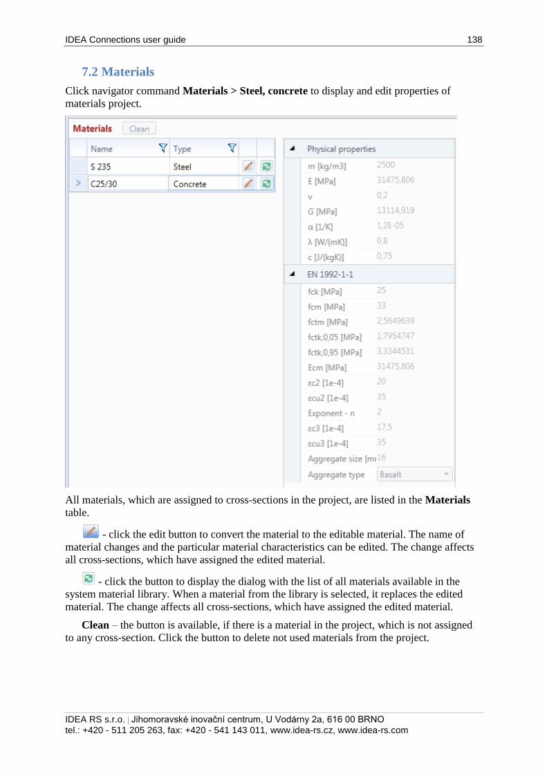
IDEA Connections user guide 138
IDEA RS s.r.o. | Jihomoravské inovační centrum, U Vodárny 2a, 616 00 BRNO
tel.: +420 - 511 205 263, fax: +420 - 541 143 011, www.idea-rs.cz, www.idea-rs.com
7.2 Materials
Click navigator command Materials > Steel, concrete to display and edit properties of
materials project.
All materials, which are assigned to cross-sections in the project, are listed in the Materials
table.
- click the edit button to convert the material to the editable material. The name of
material changes and the particular material characteristics can be edited. The change affects
all cross-sections, which have assigned the edited material.
- click the button to display the dialog with the list of all materials available in the
system material library. When a material from the library is selected, it replaces the edited
material. The change affects all cross-sections, which have assigned the edited material.
Clean – the button is available, if there is a material in the project, which is not assigned
to any cross-section. Click the button to delete not used materials from the project.
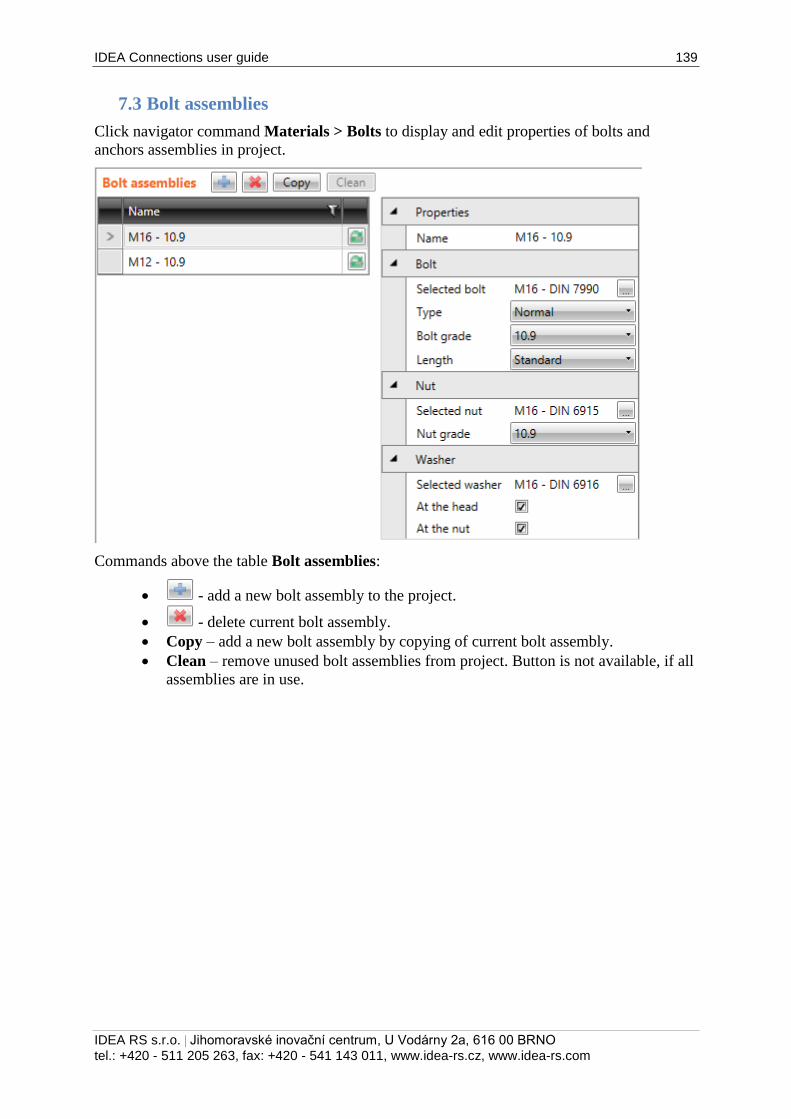
IDEA Connections user guide 139
IDEA RS s.r.o. | Jihomoravské inovační centrum, U Vodárny 2a, 616 00 BRNO
tel.: +420 - 511 205 263, fax: +420 - 541 143 011, www.idea-rs.cz, www.idea-rs.com
7.3 Bolt assemblies
Click navigator command Materials > Bolts to display and edit properties of bolts and
anchors assemblies in project.
Commands above the table Bolt assemblies:
- add a new bolt assembly to the project.
- delete current bolt assembly.
Copy – add a new bolt assembly by copying of current bolt assembly.
Clean – remove unused bolt assemblies from project. Button is not available, if all
assemblies are in use.