Embed Size (px)
Citation preview
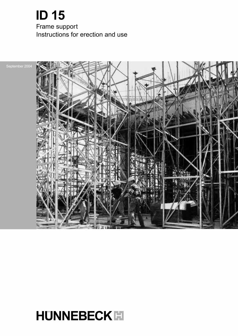
ID 15Frame supportInstructions for erection and use
September 2004
1-1182.Aufbauanl.ID15 D+GB 05.10.2004 8:56 Uhr Seite 4
1.0 Product features & information 3
2.0 Overview 4
3.0 Components 5–7
4.0 Application planning & preparatory work 8
5.0 Determination of material 9
6.0 Load-bearing capacity 10–11
7.0 ID15 Frame support with H20 beams
ID15 Frame support with R24 beams 12–13
8.0 Erection and dismantling 14–18
9.0 Application examples 19–21
10.0 Construction sites 22–23
Contents
3
ID 15
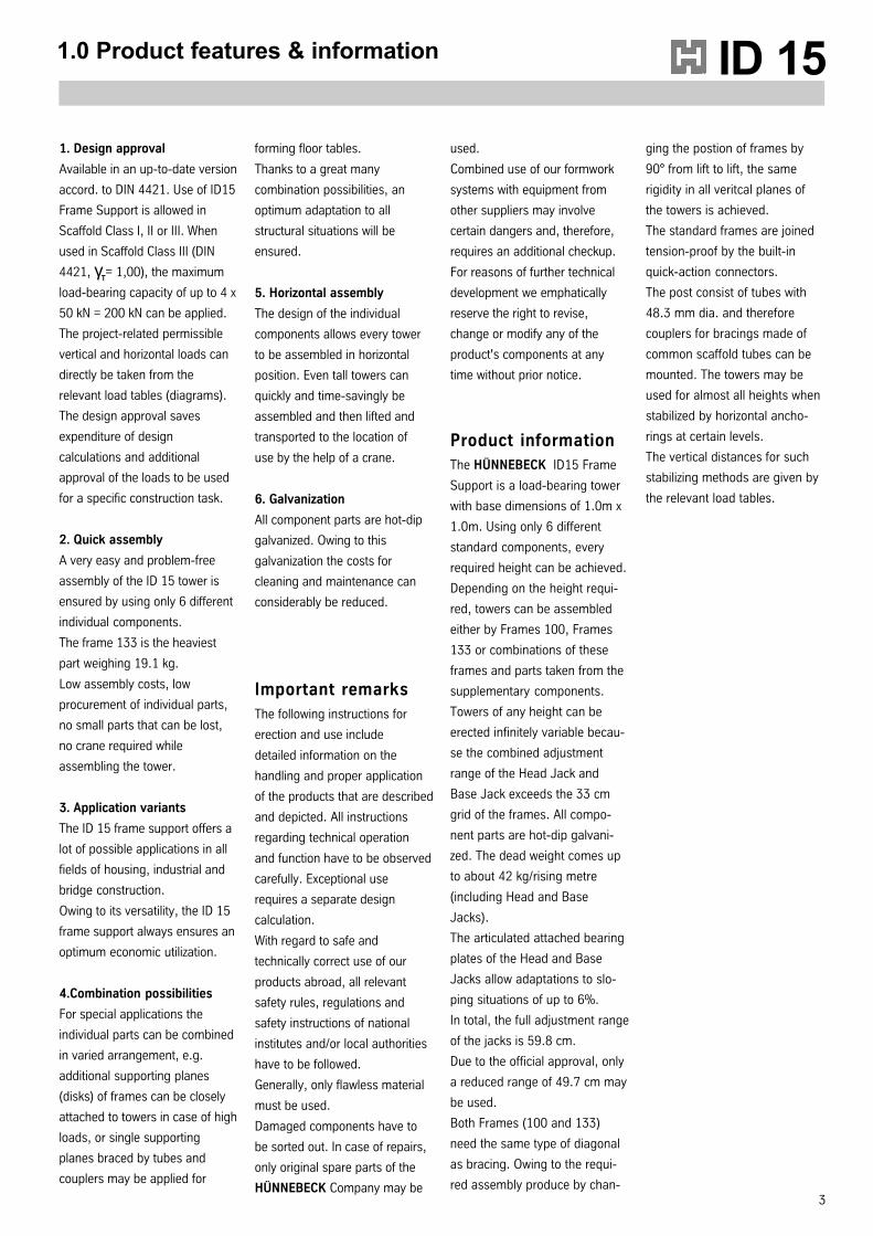
1. Design approval
Available in an up-to-date version
accord. to DIN 4421. Use of ID15
Frame Support is allowed in
Scaffold Class I, II or III. When
used in Scaffold Class III (DIN
4421, γT= 1,00), the maximum
load-bearing capacity of up to 4 x
50 kN = 200 kN can be applied.
The project-related permissible
vertical and horizontal loads can
directly be taken from the
relevant load tables (diagrams).
The design approval saves
expenditure of design
calculations and additional
approval of the loads to be used
for a specific construction task.
2. Quick assembly
A very easy and problem-free
assembly of the ID 15 tower is
ensured by using only 6 different
individual components.
The frame 133 is the heaviest
part weighing 19.1 kg.
Low assembly costs, low
procurement of individual parts,
no small parts that can be lost,
no crane required while
assembling the tower.
3. Application variants
The ID 15 frame support offers a
lot of possible applications in all
fields of housing, industrial and
bridge construction.
Owing to its versatility, the ID 15
frame support always ensures an
optimum economic utilization.
4.Combination possibilities
For special applications the
individual parts can be combined
in varied arrangement, e.g.
additional supporting planes
(disks) of frames can be closely
attached to towers in case of high
loads, or single supporting
planes braced by tubes and
couplers may be applied for
1.0 Product features & information
forming floor tables.
Thanks to a great many
combination possibilities, an
optimum adaptation to all
structural situations will be
ensured.
5. Horizontal assembly
The design of the individual
components allows every tower
to be assembled in horizontal
position. Even tall towers can
quickly and time-savingly be
assembled and then lifted and
transported to the location of
use by the help of a crane.
6. Galvanization
All component parts are hot-dip
galvanized. Owing to this
galvanization the costs for
cleaning and maintenance can
considerably be reduced.
Important remarksThe following instructions for
erection and use include
detailed information on the
handling and proper application
of the products that are described
and depicted. All instructions
regarding technical operation
and function have to be observed
carefully. Exceptional use
requires a separate design
calculation.
With regard to safe and
technically correct use of our
products abroad, all relevant
safety rules, regulations and
safety instructions of national
institutes and/or local authorities
have to be followed.
Generally, only flawless material
must be used.
Damaged components have to
be sorted out. In case of repairs,
only original spare parts of the
HÜNNEBECK Company may be
used.
Combined use of our formwork
systems with equipment from
other suppliers may involve
certain dangers and, therefore,
requires an additional checkup.
For reasons of further technical
development we emphatically
reserve the right to revise,
change or modify any of the
product's components at any
time without prior notice.
Product informationThe HÜNNEBECK ID15 Frame
Support is a load-bearing tower
with base dimensions of 1.0m x
1.0m. Using only 6 different
standard components, every
required height can be achieved.
Depending on the height requi-
red, towers can be assembled
either by Frames 100, Frames
133 or combinations of these
frames and parts taken from the
supplementary components.
Towers of any height can be
erected infinitely variable becau-
se the combined adjustment
range of the Head Jack and
Base Jack exceeds the 33 cm
grid of the frames. All compo-
nent parts are hot-dip galvani-
zed. The dead weight comes up
to about 42 kg/rising metre
(including Head and Base
Jacks).
The articulated attached bearing
plates of the Head and Base
Jacks allow adaptations to slo-
ping situations of up to 6%.
In total, the full adjustment range
of the jacks is 59.8 cm.
Due to the official approval, only
a reduced range of 49.7 cm may
be used.
Both Frames (100 and 133)
need the same type of diagonal
as bracing. Owing to the requi-
red assembly produce by chan-
ging the postion of frames by
90° from lift to lift, the same
rigidity in all veritcal planes of
the towers is achieved.
The standard frames are joined
tension-proof by the built-in
quick-action connectors.
The post consist of tubes with
48.3 mm dia. and therefore
couplers for bracings made of
common scaffold tubes can be
mounted. The towers may be
used for almost all heights when
stabilized by horizontal ancho-
rings at certain levels.
The vertical distances for such
stabilizing methods are given by
the relevant load tables.
4
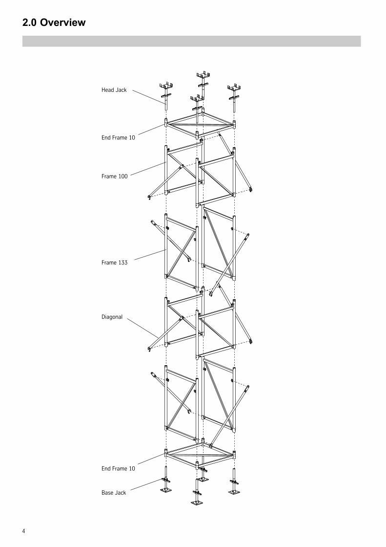
2.0 Overview
Head Jack
End Frame 10
Frame 100
Frame 133
Diagonal
End Frame 10
Base Jack
5
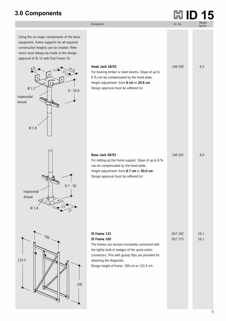
Designation Art. No.Weightkg/pce.
ID 153.0 Components
Head Jack 38/52
For bearing timber or steel beams. Slope of up to
6 % can be compensated by the head plate.
Height adjustment: from 8 cm to 29.8 cm.
Design approval must be adhered to!
8.2148 530
Base Jack 38/52
For setting-up the frame support. Slope of up to 6 %
can be compensated by the head plate.
Height adjustment: from 8.7 cm to 30.0 cm.
Design approval must be adhered to!
8.0148 552
ID Frame 133
ID Frame 100
The frames are tension-resistantly connected with
the tightly built-in wedges of the quick-action
connectors. Pins with gravity flips are provided for
attaching the diagonals.
Design height of frame: 100 cm or 133.5 cm.
19.1
16.1
057 162
057 173
17.611
8 - 29.8
8.6
Ø 1.2
Ø 3.8
8.7 - 30
17Ø 1.8 11
trapezoidal
thread
trapezoidal
thread
100
133.5
100
Using the six major components of the basic
equipment, frame supports for all required
construction heights can be created. Refe-
rence must always be made to the design
approval of ID 15 with End Frame 10.
Designation Art. No.Weightkg/pce.
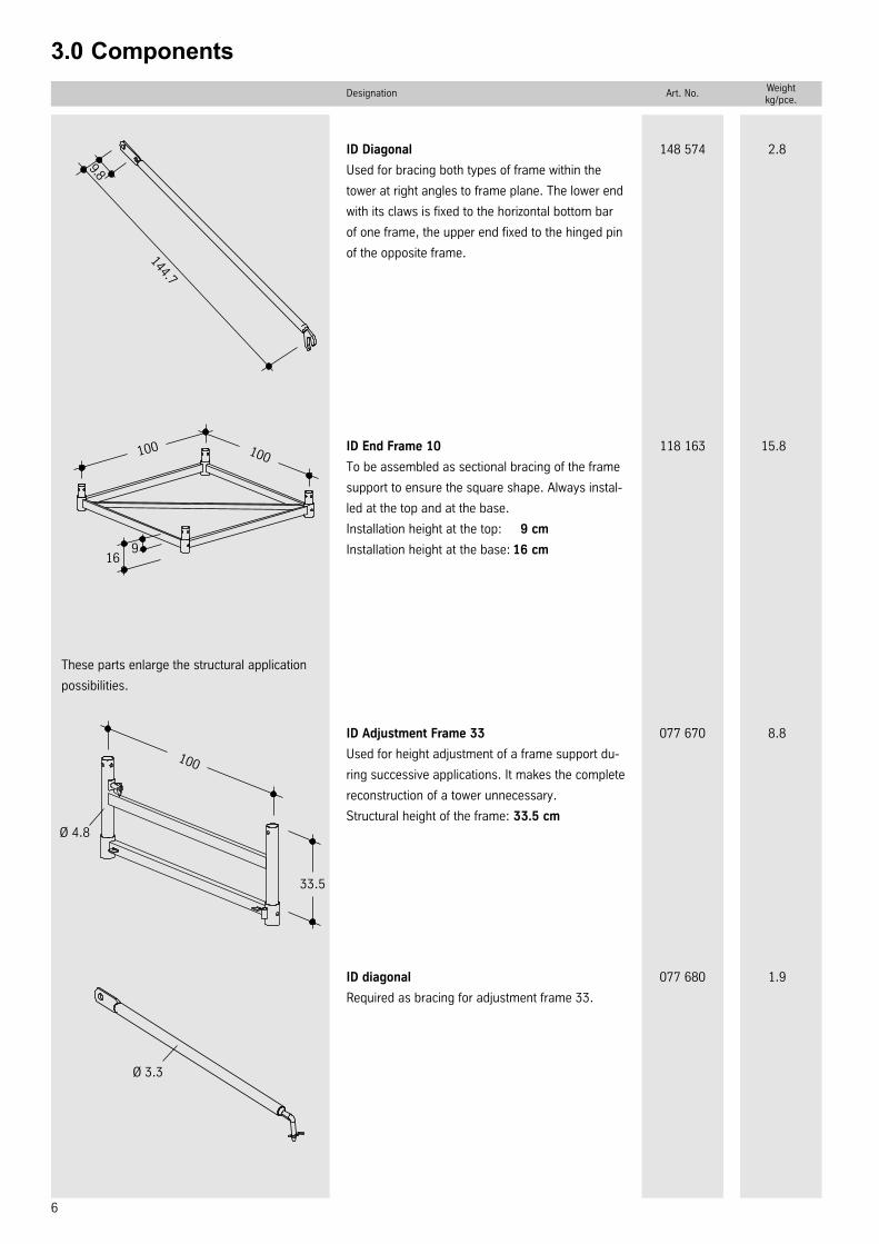
6
3.0 Components
ID Diagonal
Used for bracing both types of frame within the
tower at right angles to frame plane. The lower end
with its claws is fixed to the horizontal bottom bar
of one frame, the upper end fixed to the hinged pin
of the opposite frame.
2.8148 574
9.8
144.7
ID End Frame 10
To be assembled as sectional bracing of the frame
support to ensure the square shape. Always instal-
led at the top and at the base.
Installation height at the top: 9 cm
Installation height at the base: 16 cm
15.8118 163100 100
169
These parts enlarge the structural application
possibilities.
ID Adjustment Frame 33
Used for height adjustment of a frame support du-
ring successive applications. It makes the complete
reconstruction of a tower unnecessary.
Structural height of the frame: 33.5 cm
8.8077 670
100
33.5
Ø 4.8
ID diagonal
Required as bracing for adjustment frame 33.
1.9077 680
Ø 3.3
7
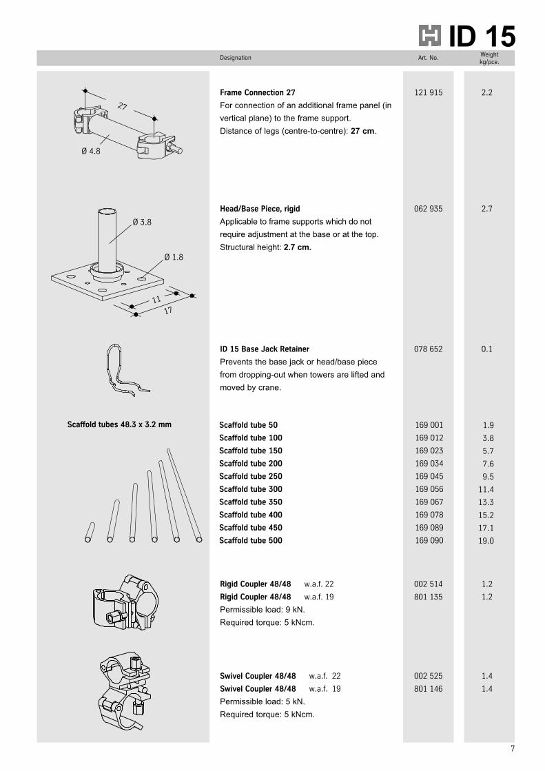
Designation Art. No.Weightkg/pce.
ID 153.0 Components3.0 Components3.0 Components3.0 Components3.0 Components
Frame Connection 27
For connection of an additional frame panel (in
vertical plane) to the frame support.
Distance of legs (centre-to-centre): 27 cm.
2.2121 915
27
Ø 4.8
1711
Ø 3.8
Ø 1.8
Head/Base Piece, rigid
Applicable to frame supports which do not
require adjustment at the base or at the top.
Structural height: 2.7 cm.
2.7062 935
ID 15 Base Jack Retainer
Prevents the base jack or head/base piece
from dropping-out when towers are lifted and
moved by crane.
0.1078 652
Scaffold tube 50
Scaffold tube 100
Scaffold tube 150
Scaffold tube 200
Scaffold tube 250
Scaffold tube 300
Scaffold tube 350
Scaffold tube 400
Scaffold tube 450
Scaffold tube 500
169 001
169 012
169 023
169 034
169 045
169 056
169 067
169 078
169 089
169 090
1.9
3.8
5.7
7.6
9.5
11.4
13.3
15.2
17.1
19.0
Scaffold tubes 48.3 x 3.2 mm
Rigid Coupler 48/48 w.a.f. 22
Rigid Coupler 48/48 w.a.f. 19
Permissible load: 9 kN.
Required torque: 5 kNcm.
1.2
1.2
002 514
801 135
Swivel Coupler 48/48 w.a.f. 22
Swivel Coupler 48/48 w.a.f. 19
Permissible load: 5 kN.
Required torque: 5 kNcm.
1.4
1.4
002 525
801 146
8
4.0 Application planning & preparatory work
The quick and safe erection of ID15
frame supports can be significantly
improved by precedent application
planning and preparatory work.
Application planning
Drawings, material list,
instructions for erection and use
as well as the latest approvals of
the design analyses should
completely be handed over to
the job-side.
Preparations for erecting
Check the material with regard
to completeness and flawless-
ness and store it up clearly
organized.
Sort out damaged parts and
place them separately, order
replacemant parts. Damaged
parts may also be, e.g., head
jacks with bearing plates which
show too much slope.
Store and protect small
quantities of material which will
not be required during
reconstruction of towers.
Arrange everything, if
necessary, for marking the final
positions of the towers on the
foundations in time.
Instruct site staff for the
assembly and operation
procedures as far as necessary.
* Wind pressure:
q = 0 within the building (no wind)
q = 0.5 kN/m² 0-8 m over ground
q = 0.8 kN/m² > 8 -20 m over ground
q = 1.1 kN/m² > 20-100 m over ground
shape coefficient for ID15 tower: 1.3
* Wind load per rising „m“ of ID 15: 1.3 • 0.4 m²/m • q
= 0.52 m²/m • q
0 to 8 m = 0.52 • 0.5 = 0.26 kN/m
> 8 to 20 m = 0.52 • 0.8 = 0.42 kN/m
> 20 to 100 m = 0.52 • 1.1 = 0.57 kN/m
Static fundamentals for the
design analsis of slab supporting
systems.
Weight density of freshly placed
concrete:
γc = 26.0 kN/m³
Dead load resulting from formwork,
shoring structure, steel beams and/
or timber formwork beams.
Live loads according to DIN 4421
Horizontal loads from wind
pressure, DIN 1055, Teil 4.*
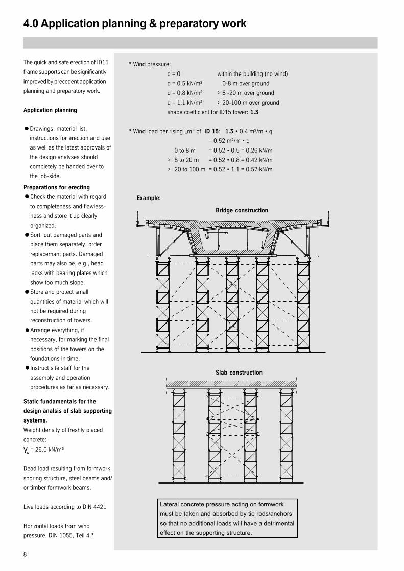
Bridge construction
Example:
Slab construction
Lateral concrete pressure acting on formwork
must be taken and absorbed by tie rods/anchors
so that no additional loads will have a detrimental
effect on the supporting structure.
ID 15
9
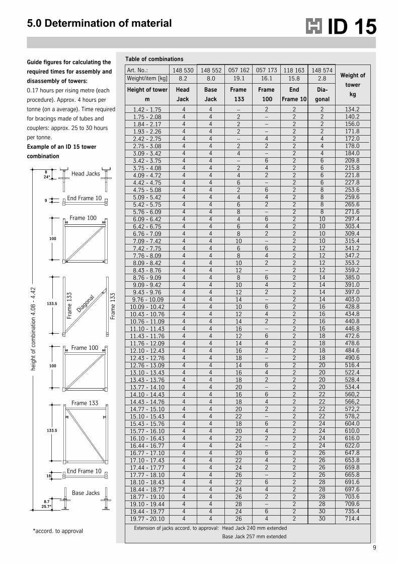
5.0 Determination of material
1.42 - 1.751.75 - 2.081.84 - 2.171.93 - 2.262.42 - 2.752.75 - 3.083.09 - 3.423.42 - 3.753.75 - 4.084.09 - 4.724.42 - 4.754.75 - 5.085.09 - 5.425.42 - 5.755.76 - 6.096.09 - 6.426.42 - 6.756.76 - 7.097.09 - 7.427.42 - 7.757.76 - 8.098.09 - 8.428.43 - 8.768.76 - 9.099.09 - 9.429.43 - 9.76
9.76 - 10.0910.09 - 10.4210.43 - 10.7610.76 - 11.0911.10 - 11.4311.43 - 11.7611.76 - 12.0912.10 - 12.4312.43 - 12.7612.76 - 13.0913.10 - 13.4313.43 - 13.7613.77 - 14.1014.10 - 14.4314.43 - 14.7614.77 - 15.1015.10 - 15.4315.43 - 15.7615.77 - 16.1016.10 - 16.4316.44 - 16.7716.77 - 17.1017.10 - 17.4317.44 - 17.7717.77 - 18.1018.10 - 18.4318.44 - 18.7718.77 - 19.1019.10 - 19.4419.44 - 19.7719.77 - 20.10
Height of tower
m
Head
Jack
Base
Jack
Frame
133
Frame
100
End
Frame 10
Dia-
gonal
Extension of jacks accord. to approval: Head Jack 240 mm extended
Base Jack 257 mm extended
Weight of
tower
kg
Art. No.:
Weight/item [kg]
148 530
8.2
148 552
8.0
057 162
19.1
057 173
16.1
118 163
15.8
148 574
2.8
Table of combinationsGuide figures for calculating the
required times for assembly and
disassembly of towers:
0.17 hours per rising metre (each
procedure). Approx. 4 hours per
tonne (on a average). Time required
for bracings made of tubes and
couplers: approx. 25 to 30 hours
per tonne.
Example of an ID 15 tower
combination
Head Jacks
End Frame 10
Frame 100
Diago
nal
Fram
e 1
33
Fram
e 1
33
Frame 100
Frame 133
End Frame 10
Base Jacks
824*
9
100
hei
gh
t o
f co
mb
ina
tion
4.0
8 -
4.4
2
133.5
100
133.5
16
8.725.7*
*accord. to approval
444444444444444444444444444444444444444444444444444444444
444444444444444444444444444444444444444444444444444444444
–222–24–2462468468
1068
10128
101214101214161214161814161820161820221820222420222426222426282426
2–––42–642–642–642–642–642–642–642–642–642–642–642–642–64
222222222222222222222222222222222222222222222222222222222
222244466668888
101010101212121214141414161616161818181820202020222222222424242426262626282828283030
134.2140.2156.0171.8172.0178.0184.0209.8215.8221.8227.8253.6259.6265.6271.6297.4303.4309.4315.4341.2347.2353.2359.2 385.0391.0397.0403.0428.8434.8440.8446.8472.6478.6484.6490.6516.4522.4528.4534.4560,2566,2572,2578,2604.0610.0616.0622.0647.8653.8659.8665.8691.6697.6703.6709.6735.4714.4
10
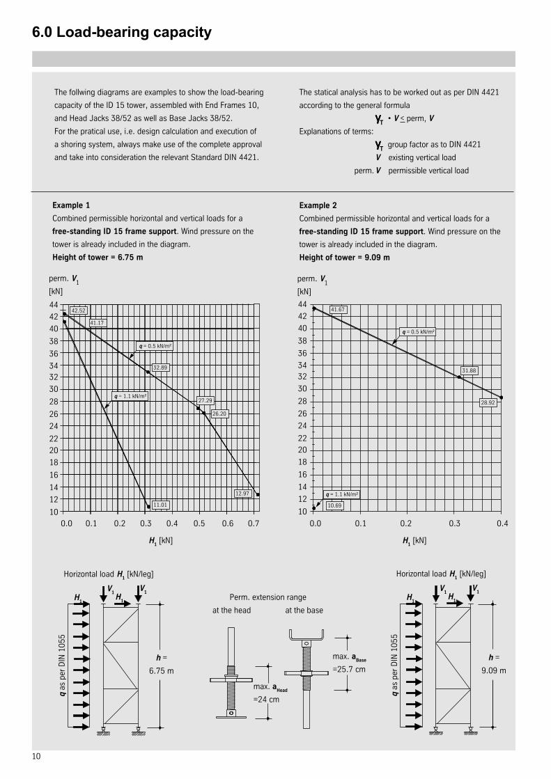
The follwing diagrams are examples to show the load-bearing
capacity of the ID 15 tower, assembled with End Frames 10,
and Head Jacks 38/52 as well as Base Jacks 38/52.
For the pratical use, i.e. design calculation and execution of
a shoring system, always make use of the complete approval
and take into consideration the relevant Standard DIN 4421.
Example 1
Combined permissible horizontal and vertical loads for a
free-standing ID 15 frame support. Wind pressure on the
tower is already included in the diagram.
Height of tower = 6.75 m
0.0 0.1 0.2 0.3 0.4 0.5 0.6 0.7 0.0 0.1 0.2 0.3 0.4
10
12
14
16
18
20
22
24
26
28
30
32
34
36
38
40
42
44
10
12
14
16
18
20
22
24
26
28
30
32
34
36
38
40
42
44
perm. V1
[kN]
perm. V1
[kN]
Example 2
Combined permissible horizontal and vertical loads for a
free-standing ID 15 frame support. Wind pressure on the
tower is already included in the diagram.
Height of tower = 9.09 m
h =
6.75 m
Horizontal load H1 [kN/leg]
H1 [kN]
H1
H1
V1
V1
q as
per
DIN
10
55
Perm. extension range
at the head at the base
max. aHead
=24 cm
max. aBase
=25.7 cm
h =
9.09 m
Horizontal load H1 [kN/leg]
H1
H1
V1
V1
q as
per
DIN
10
55
41.17
q = 0.5 kN/m²
42.52
q = 1.1 kN/m²
11.01
12.97
27.29
26.20
32.89
10.69
41.67
q = 0.5 kN/m²
31.88
28.92
q = 1.1 kN/m²
H1 [kN]
6.0 Load-bearing capacity
The statical analysis has to be worked out as per DIN 4421
according to the general formula
γγγγγT
• V < perm, V
Explanations of terms:
γγγγγT
group factor as to DIN 4421
V existing vertical load
perm. V permissible vertical load
11
ID 15
Perm. extension range
at the head at the base
The size of the group factor depends on the scaffold class of
DIN 4421 which is made reference to. As individual supporting
member, the ID 15 Tower with End Frame 10 is in conformance
with the high requirements of the scaffod class III as stated in
the approval. That is why the ID 15 frame support can be used
in each of the three classes, especially also in class III with the
most favourable group factor of γγγγγT
=1.00.
The loads stated in the approval of the tower can be fully
applied to within the scaffold class III.
The necessary safety against tilting and sliding of individual
frame supports must be proved separately according to the
relevant regulations for the stability of such structures.
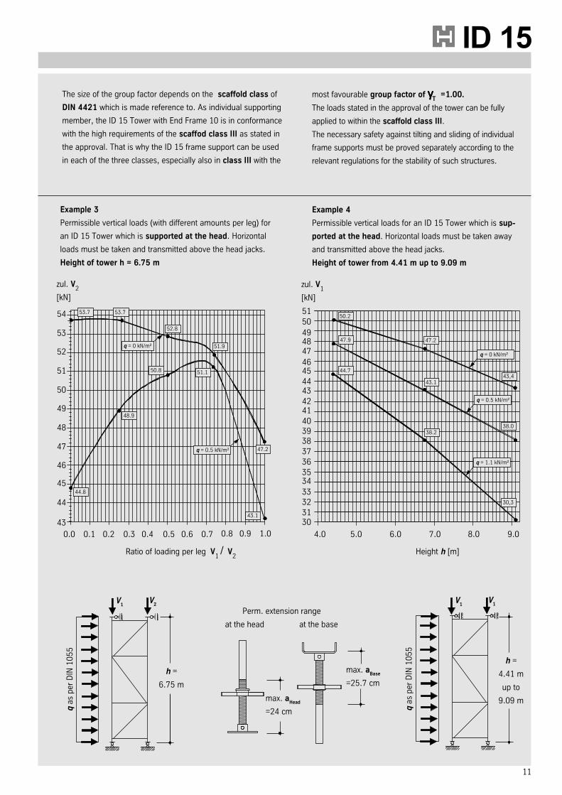
Example 3
Permissible vertical loads (with different amounts per leg) for
an ID 15 Tower which is supported at the head. Horizontal
loads must be taken and transmitted above the head jacks.
Height of tower h = 6.75 m
0.0 0.1 0.2 0.3 0.4 0.5 0.6 0.7 4.0 5.0 6.0 7.0 9.0
43 3031
3233
3435
36
37
383940
4142
4344
4546
47
zul. V2
[kN]
zul. V1
[kN]
Example 4
Permissible vertical loads for an ID 15 Tower which is sup-
ported at the head. Horizontal loads must be taken away
and transmitted above the head jacks.
Height of tower from 4.41 m up to 9.09 m
h =
6.75 m
Height h [m]
V1
V2
q as
per
DIN
10
55
max. aHead
=24 cm
max. aBase
=25.7 cm
h =
4.41 m
up to
9.09 m
V1
V1
q as
per
DIN
10
55
53.7
q = 0.5 kN/m²
43.1
47.2
50.8
50.2
q = 0.5 kN/m²
47.2
38.0
q = 1.1 kN/m²
44
45
46
47
48
49
50
51
52
53
54 53.7
51.1
48.9
44.8
q = 0 kN/m²
52.8
51.9
8.0
4849
50
51
47.9
44.7
43.1
38.2
q = 0 kN/m²
43,4
30,3
Ratio of loading per leg V1/ V
2
0.8 0.9 1.0
12
t slab thickness [cm]q total loading [kN/m²]
6019.0
6520.5
7022.1
7523.7
8025.2
8526.8
9028.3
9529.9
10031.3
10532.6
11033.9
11535.2
12036.5
12537.8
L allowable spann of secondary beam [m]2.84
2.40
2.26
2.05
1.84
1.74
1.55
2.77
2.34
2.201.97
1.71
1.61
1.43
2.70
2.28
2.131.90
1.59
1.491.33
2.64
2.23
2.06
1.84
1.49
1.39
1.24
2.59
2.18
1.99
1.75
1.40
1.31
1.16
2.54
2.12
1.931.64
1.31
1.231.10
2.49
2.06
1.88
1.55
1.24
1.16
1.04
2.45
2.00
1.83
1.47
1.18
1.10
---
2.40
1.96
1.761.41
1.13
1.06
---
2.37
1.92
1.691.35
1.08
1.01---
2.33
1.88
1.62
1.30
1.04
---
---
2.30
1.85
1.56
1.25
1.00
---
---
2.26
1.81
1.511.21
---
---
---
2.23
1.75
1.46
1.17
---
---
---
0.200.330.400.500.630.670.75
Spacing of second. beams [m]
A allowable span of primary beams [m], (double beamsh: 2 x H20 timber beams)resulting loads per leg [kN]
2.05
29.01.84
33.6
1.55
36.2
1.33
38.6
1.97
30.5
1.7134.8
1.43
37.41.22
40.0
1.90
32.1
1.5935.8
1.33
38.6
1.14
41.3
1.84
33.6
1.4936.8
1.24
39.71.06
42.7
1.75
34.6
1.4037.8
1.16
40.9---
---
1.64
35.4
1.3138.7
1.10
42.1
---
---
1.55
36.2
1.2439.7
1.04
43.2---
---
1.47
36.9
1.1840.7
---
---
---
---
1.41
37.6
1.1341.5
---
------
---
1.35
38.3
1.0842.3
---
---
---
---
1.30
38.9
1.0443.2
---
------
---
1.25
39.6
1.0044.0
---
---
---
---
1.21
40.2
------
---
---
---
---
1.17
40.9
------
---
------
---
1.00
1.25
1.50
1.75
b Loading widths [m](b=L/2 + 0,5 m)
7.0 ID 15 Frame Support with H 20 beams
„t“ slab thickness [cm]„q“ total loading [kN/m²]
145.39
165.91
186.43
206.95
227.47
247.99
268.51
289.03
309.61
3511.2
4012.7
4514.3
5015.9
5517.4
L = allowable span of secondary beam [m]4.00
3.83
3.613.35
3.11
3.042.92
4.003.68
3.46
3.212.98
2.92
2.80
4.003.54
3.33
3.092.87
2.81
2.70
4.003.43
3.22
2.992.78
2.72
2.61
3.943.32
3.13
2.902.69
2.64
2.54
3.833.23
3.04
2.822.62
2.56
2.47
3.733.15
2.96
2.752.55
2.50
2.40
3.653.08
2.89
2.692.49
2.44
2.35
3.573.01
2.83
2.632.44
2.39
2.29
3.392.86
2.69
2.502.32
2.27
2.18
3.252.74
2.58
2.392.22
2.17
2.05
3.132.64
2.48
2.302.12
2.05
1.93
3.022.55
2.40
2.222.01
1.95
1.83
2.932.47
2.32
2.141.92
1.86
1.68
0.200.330.400.500.630.670.75
Spacing of second beams [m]
„A“ allowable span of primary beams [m], (double beams: 2 x H20 timber beams)resulting loads per leg [kN]
3.35
11.7
3.1113.8
2.92
15.92.78
17.8
2.66
19.7
2.55
21.6
2.44
23.2
3.2112.4
2.98
14.72.80
16.9
2.6618.9
2.55
21.0
2.45
22.9
2.33
24.6
3.0913.2
2.87
15.62.70
17.9
2.5720.1
2.46
22.2
2.35
24.2
2.23
26.0
2.9913.9
2.78
16.42.61
18.8
2.4821.2
2.37
23.5
2.26
25.5
2.15
27.3
2.9014.6
2.69
17.22.54
19.8
2.4122.3
2.30
24.7
2.18
26.7
2.07
28.7
2.8215.3
2.62
18.12.47
20.8
2.3423.4
2.24
25.9
2.11
28.0
2.00
30.0
2.7516.0
2,55
18.92.40
21.7
2.2824.4
2.17
27.0
2.04
29.1
1.94
31.3
2.6916.6
2,49
19.72.35
22.7
2.2325.5
2.10
28.0
1.98
30.3
1.88
32.5
2.63
17.4
2.44
20.72.29
23.7
2.1826.7
2.04
29.2
1.92
31.6
1.82
33.9
2.5019.5
2.32
23.22.18
26.7
2.0229.5
1.89
32.3
1.75
34.6
1,58
36.0
2.3921.6
2.22
25.62.05
29.1
1.9032.2
1.73
34.7
1.54
36.3
1.38
37.9
2.3023.6
2.12
27.81.93
31.4
1.7634.5
1.54
36.3
1.37
38.1
1.23
39.9
2.2225.6
2.01
29.81.83
33.7
1.5935.9
1.39
37.9
1.23
39.8
1.11
41.8
2.1427.4
1.92
31.71.68
35.1
1.4437.2
1.26
39.4
1.12
41.6
1.01
43.8
1.00
1.25
1.50
1.75
2.00
2.25
2.50
„b“ Loading widths [m](b=L/2 + 0.5 m)
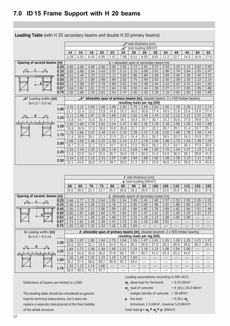
Loading Table (with H 20 secondary beams and double H 20 primary beams)
Deflections of beams are limited to L/500.
This loading table should be considered as general
help for technical elaborations, but it does not
replace a seperate statical proof of the final stability
of the whole structure.
Loading assumptions according to DIN 4421:
wf
dead load for formwork = 0.25 kN/m²
wc
load of concrete = t [m] x 26.0 kN/m³
(weight density of concrete = 26 kN/m³
p live load = 0.20 x wc
(minimum 1.5 kN/m², maximal 5.0 kN/m²)
Total load q = wf+ w
c+ p [kN/m²]
50 50L
b
50 50A
50 50L
b
50 50A
13
ID 15
t slab thickness [cm]q total loading [kN/m²]
6019.0
6520.5
7022.1
7523.7
8025.2
8526.8
9028.3
9529.9
10031.3
10532.6
11033.9
11535.2
12036.5
12537.8
L zulässige Spannweite der Belagträger [m]3.26
2.66
2.66
2.37
2.07
2.07
1.78
3.26
2.66
2.372.07
2.07
1.78
1.78
3.26
2.66
2.372.07
1.78
1.781.48
2.96
2.66
2.37
2.07
1.78
1.48
1.48
2.96
2.37
2.07
2.07
1.78
1.48
1.18
2.96
2.37
2.071.78
1.48
1.181.18
2.96
2.37
2.07
1.78
1.48
1.18
0.89
2.96
2.37
2.07
1.78
1.18
1.18
0.89
2.66
2.07
2.071.78
1.18
0.89
0.59
2.66
2.07
2.071.48
0.89
0.890.59
2.66
2.07
1.78
1.48
0.89
0.89
0.59
2.66
2.07
1.78
1.48
0.89
0.59
0.59
2.66
2.07
1.781.18
0.89
0.59
0.59
2.66
2.07
1.78
1.18
0.59
0.59
---
0.200.330.400.500.630.670.75
Spacing of second. beams [m]
A allowable span of primary beams [m], (double beamsh: 2 x R20 timber beams)resulting loads per leg [kN]
2.37
31.92.07
36.4
1.78
39.5
1.48
41.2
2.07
31.5
2.0739.4
1.78
42.71.48
44.6
2.07
33.9
1.7838.3
1.48
41.1
1.18
42.2
2.07
36.3
1.7841.0
1.48
44.01.18
45.2
2.07
38.7
1.7843.7
1.48
46.91.18
48.2
1.78
37.2
1.4841.5
1.18
43.8
1.18
51.2
1.78
39.3
1.4843.9
1.18
46.40.89
46.8
1.78
41.5
1.4846.3
1.18
49.0
0.89
49.4
1.78
43.4
1.1842.7
1.18
51.20.89
51.6
1.48
40.4
1.1844.4
0.89
46.1
---
---
1.48
42.0
1.1846.2
0.89
47.9---
---
1.48
43.6
1.1848.0
0.89
49.8
---
---
1.48
45.2
1.1849.8
0.89
51.6
---
---
1.48
46.8
1.1851.5
---
------
---
1.00
1.25
1.50
1.75
b Loading widths [m](b=L/2 + 0.5 m)
7.0 ID 15 Frame Support with R 24 beams
t slab thickness [cm]q total loading [kN/m²]
145.39
165.91
186.43
206.95
227.47
247.99
268.51
289.03
309.61
3511.2
4012.7
4514.3
5015.9
5517.4
L allowable span of secondary beam [m]5.33
4.44
4.143.85
3.55
3.553.55
5.034.44
4.14
3.853.55
3.26
3.26
5.034.14
3.85
3.553.26
3.26
3.26
4.744.14
3.85
3.553.26
3.26
2.96
4.743.85
3.55
3.263.26
2.96
2.96
4.443.85
3.55
3.262.96
2.96
2.96
4.443.55
3.55
3.262.96
2.96
2.66
4.143.55
3.26
3.262.96
2.96
2.66
4.143.55
3.26
2.962.96
2.66
2.66
3.853.26
3.26
2.962.66
2.66
2.37
3.853.26
2.96
2.662.37
2.37
2.37
3.552.96
2.96
2.662.37
2.37
2.07
3.552.96
2.66
2.372.37
2.07
2.07
3.552.96
2.66
2.372.07
2.07
1.78
0.200.330.400.500.630.670.75
Spacing of second. beams [m]
„A“ allowable span of primary beams [m], (double beams: 2 x R24 timber beams)resulting loads per leg [kN]
3.85
13.1
3.5515.3
3.55
18.43.26
20.1
2.96
21.3
2.96
24.0
2.66
24.7
3.8514.3
3.55
16.83.26
18.9
2.9620.5
2.96
23.4
2.66
24.4
2.66
27.1
3.5514.6
3.26
17.13.26
20.5
2.9622.3
2.66
23.6
2.66
26.5
2.37
27.1
3.5515.8
3.26
18.52.96
20.6
2.9624.1
2.66
25.5
2.66
28.6
2.37
29.3
3.2615.9
3.26
19.92.96
22.2
2.6623.9
2.66
27.4
2.37
28.3
2.37
31.4
3.2617.0
2.96
19.82.96
23.7
2.6625.6
2.37
26.9
2.37
30.3
2.07
30.7
3.2618.1
2.96
21.12.66
23.4
2.6627.3
2.37
28.7
2.37
32.2
2.07
32.7
3.2619.2
2.96
22.32.66
24.8
2.3726.6
2.37
30.4
2.07
31.2
2.07
34.7
2.96
19.0
2.96
23.82.66
26.4
2.3728.3
2.37
32.4
2.07
33.2
2.07
36.9
2.9622.1
2.66
25.62.37
28.2
2.3732.9
2.07
34.3
2.07
38.6
1.78
38.8
2.6623.3
2.37
26.82.37
32.2
2.0734.2
2.07
39.1
1.78
39.8
1.48
39.5
2.6626.2
2.37
30.12.07
32.9
2.0738.4
1.78
39.7
1.48
39.9
1.48
44.3
2.3726.7
2.37
33.42.07
36.5
1.7838.5
1.48
39.3
1.48
44.2
1.18
43.3
2.3729.3
2.07
33.41.78
36.2
1.7842.3
1.48
43.2
1.18
42.8
1.18
47.5
1.00
1.25
1.50
1.75
2.00
2.25
2.50
b Loading widths [m](b=L/2 + 0,5 m)
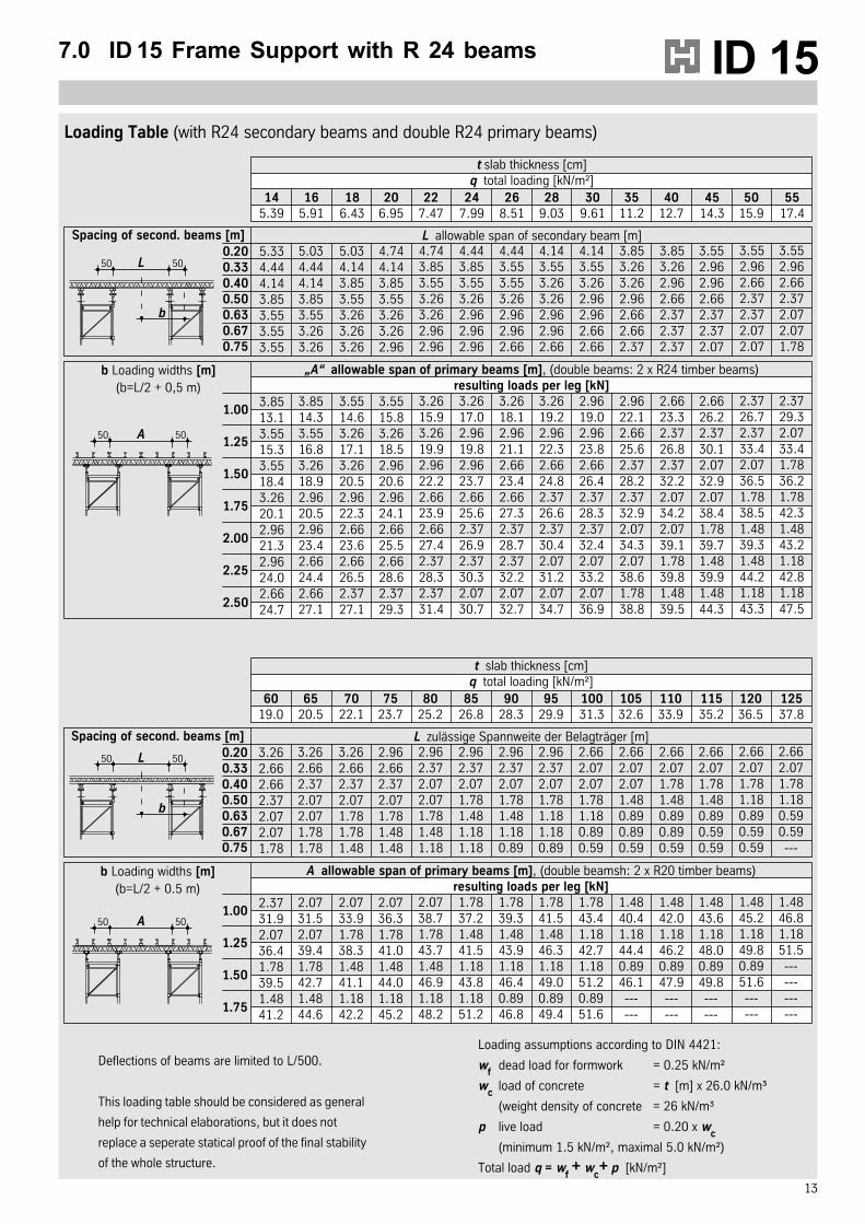
Loading Table (with R24 secondary beams and double R24 primary beams)
50 50L
b
50 50A
50 50L
b
50 50A
Deflections of beams are limited to L/500.
This loading table should be considered as general
help for technical elaborations, but it does not
replace a seperate statical proof of the final stability
of the whole structure.
Loading assumptions according to DIN 4421:
wf
dead load for formwork = 0.25 kN/m²
wc
load of concrete = t [m] x 26.0 kN/m³
(weight density of concrete = 26 kN/m³
p live load = 0.20 x wc
(minimum 1.5 kN/m², maximal 5.0 kN/m²)
Total load q = wf+ w
c+ p [kN/m²]
14
8.0 Erection and dismantling
Basic hints:
Preassemble ID15 towers according to the required height combinations and the „sequence assembly“.
Install frames and stabilizing diagonals in one vertical tower plane alternately from one lift to another.
Adjust head and base jacks at rough extension lengths. It should be noted that the adjusted length of the head jack must
have enough reserve for releasing from load when striking the towers after concreting.
Erect preassembled towers by crane. For this, attach the crane ropes to the horizontal members of the upper frames.
Do not use neither the end frame nor the head jacks.
Base jacks may only stand on a sturdy foundation. The allowable inclination can be of up to a maximum of 6%.
Erect all frame supports perpendicularly before loading.
Install bracings (scaffold tubes with couplers) if required for statical reasons or some other purpose.
Simple auxiliary bracings or provisions against tilting of towers must generally be taken into consideration during erection
and striking. Normally, it might be sufficient to install only horizontal scaffold tubes (48.3 mm dia.) which are connected to
all neighbouring legs of towers by means of rigid couplers 48/48. It is advisable to provide the tubes of the bracings as
close as possible to existing walls or columns (piers, etc.) for transmitting forces. Single towers must be stabilized to the
ground by tubes and couplers.
Final height adjustment (levelling) should be performed at the head jacks after placing the primary beams. The head jacks
can adapt to a 6% pitch. Greater pitches have to be compensated for by means of timber wedges (hard wood).
All aspects of the approval have to be adhered to.
Furthermore, the „Safety Rules and Requirements for Protection of Health in Falsework and Formwork Construction“ as well
as other relevant national or local regulations must be paid attention to (Germany: BBG, Doc. No. ZH 1/603).
Dismantling:
It is advisable to lower shoring systems formed by frame supports by releasing the head jacks. This is especially necessary when
built-in bracings of tubes and couplers do not allow for a smooth screwing down of the base jacks.
The frame supports can be dismantled after the formwork and the timber and/or steel beams have been removed from the top of
the lowered towers.
Should there be no possibility of getting the towers to an opening in the slab in order to pick them up by crane and shift them out
of the building area, then the towers may be dismantled in their positions.
This dismantling in upright normally starts with removing the head jacks and then by taking away one component after another.
The individual components can then be transported in packages to the next site of use or the storage area again.
ID 15
15
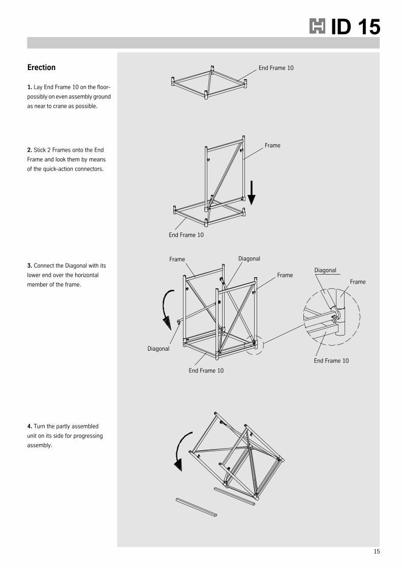
Erection
1. Lay End Frame 10 on the floor-
possibly on even assembly ground
as near to crane as possible.
2. Stick 2 Frames onto the End
Frame and look them by means
of the quick-action connectors.
3. Connect the Diagonal with its
lower end over the horizontal
member of the frame.
4. Turn the partly assembled
unit on its side for progressing
assembly.
End Frame 10
End Frame 10
Frame
Diagonal
Frame
Frame Diagonal
End Frame 10
End Frame 10
Diagonal
Frame
16
Import note:
When lifting towers by crane,
make sure not to attach crane
ropes or slings to the un-
secured top End Frame 10
but to the horizontal members
of the vertical frames directly
below this. Lifting towers into
upright position after
assembling can be performed
up to maximum heights of
approximately 10 m.
8.0 Erection and dismantling
Erection
5. Stick further frames on and
lock them with the quick-action
connectors.
6. Attach next frames. Continue
according to the before
mentioned assembly procedure
until the required combination
height has been reached.
7. Place End Frame on the last
two vertical Frames.
8. Insert Head Jacks into the
End Frame.
Quick-action connector
(unlocked)
Quick-action connector
(locked)
End Frame
End FrameHead Jack
Jack Retainer
Jack Retainer
ID 15
17
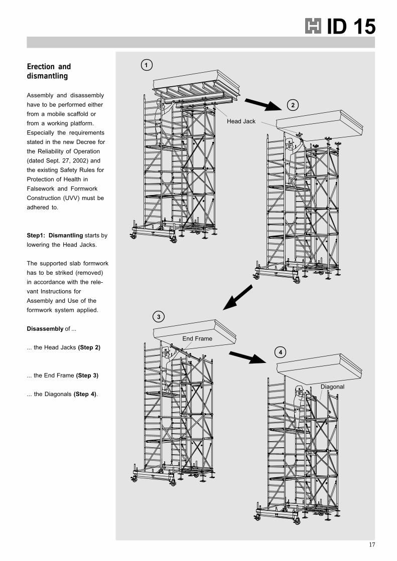
Erection anddismantling
Assembly and disassembly
have to be performed either
from a mobile scaffold or
from a working platform.
Especially the requirements
stated in the new Decree for
the Reliability of Operation
(dated Sept. 27, 2002) and
the existing Safety Rules for
Protection of Health in
Falsework and Formwork
Construction (UVV) must be
adhered to.
Step1: Dismantling starts by
lowering the Head Jacks.
The supported slab formwork
has to be striked (removed)
in accordance with the rele-
vant Instructions for
Assembly and Use of the
formwork system applied.
Disassembly of ...
... the Head Jacks (Step 2)
... the End Frame (Step 3)
... the Diagonals (Step 4).
1
Head Jack
End Frame
Diagonal
2
3
4
18
8.0 Erection and dismantling
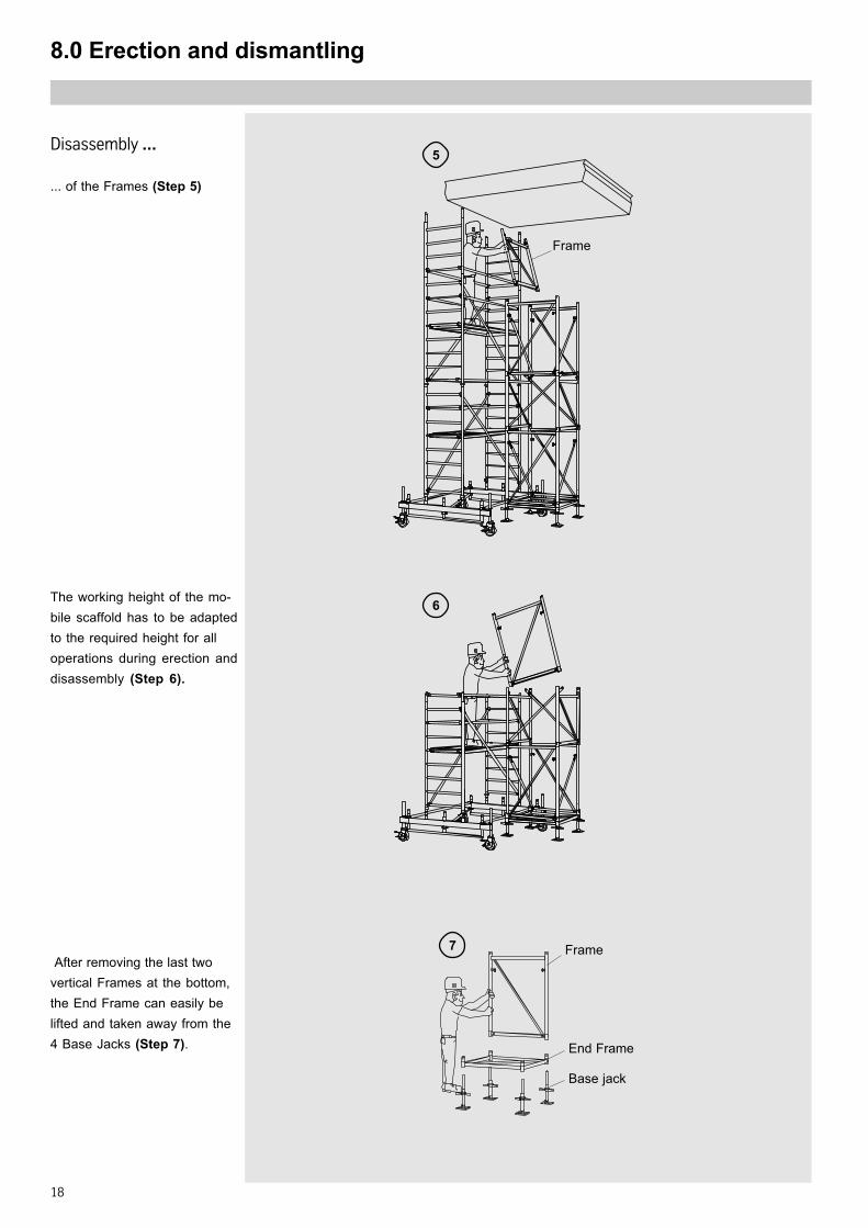
Disassembly ...
... of the Frames (Step 5)
After removing the last two
vertical Frames at the bottom,
the End Frame can easily be
lifted and taken away from the
4 Base Jacks (Step 7).
The working height of the mo-
bile scaffold has to be adapted
to the required height for all
operations during erection and
disassembly (Step 6).
Frame
Frame
End Frame
Base jack
7
5
6
ID 15
19
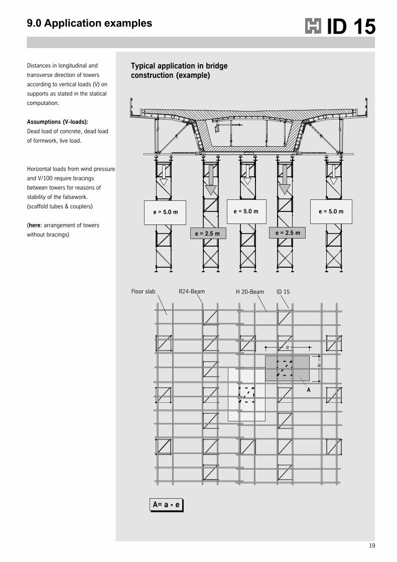
9.0 Application examples
Distances in longitudinal and
transverse direction of towers
according to vertical loads (V) on
supports as stated in the statical
computation.
Assumptions (V-loads):
Dead load of concrete, dead load
of formwork, live load.
Horizontal loads from wind pressure
and V/100 require bracings
between towers for reasons of
stability of the falsework.
(scaffold tubes & couplers)
(here: arrangement of towers
without bracings)
e = 5.0 m
e = 2.5 m
e = 5.0 m
e = 2.5 m
a
e
Typical application in bridgeconstruction (example)
Floor slab R24-Beam H 20-Beam ID 15
A
A= a e·
e = 5.0 m
20
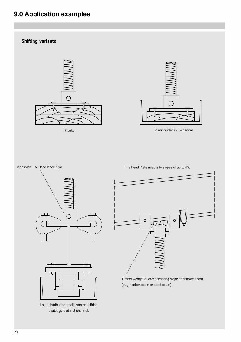
9.0 Application examples
Shifting variants
Planks Plank guided in U-channel
Load-distributing steel beam on shifting
skates guided in U-channel.
The Head Plate adapts to slopes of up to 6%
Timber wedge for compensating slope of primary beam
(e. g. timber beam or steel beam)
if possible use Base Piece rigid
21
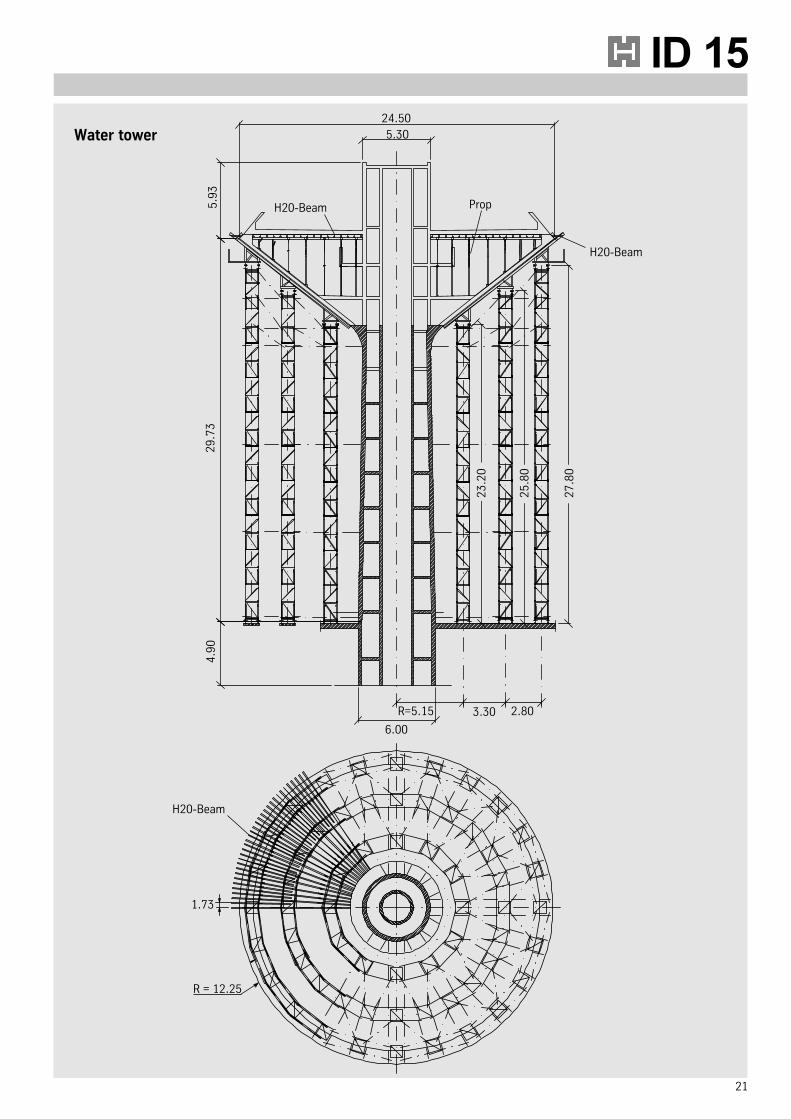
ID 1524.50
5.30
5.9
32
9.7
34
.90
6.00
3.30 2.80R=5.15
PropH20-Beam
23
.20
H20-Beam
H20-Beam
1.73
R = 12.25
25
.80
27
.80
Water tower
22
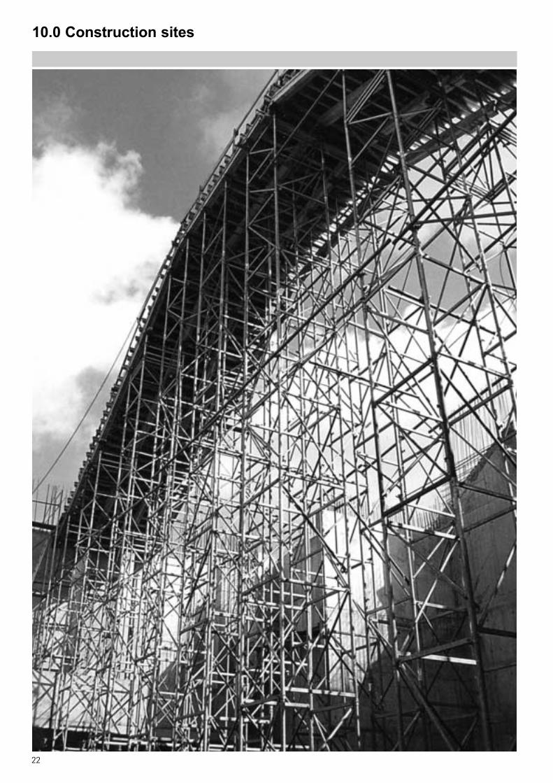
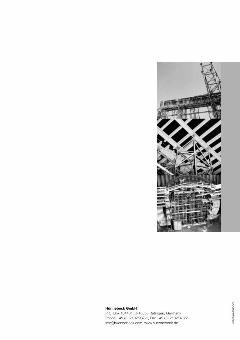
10.0 Construction sites
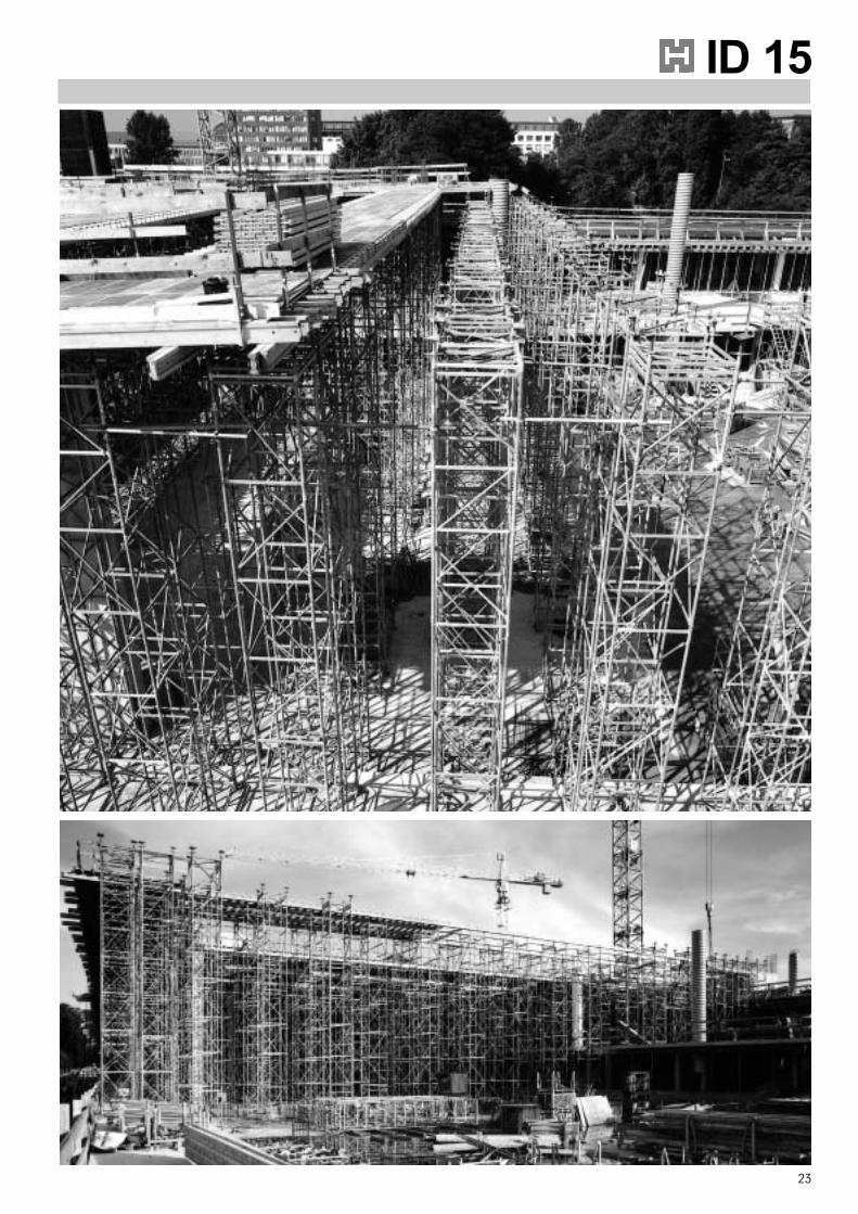
23
ID 1510.0 Construc10.0 Construc10.0 Construc10.0 Construc10.0 Construction sitestion sitestion sitestion sitestion sites
Hünnebeck GmbHP. O. Box 104461, D-40855 Ratingen, GermanyPhone +49 (0) 2102/937-1, Fax +49 (0) 2102/[email protected], www.huennebeck.de G
B-0
9-04
-200
0-D
DH
1-1182.Aufbauanl.ID15 D+GB 05.10.2004 9:55 Uhr Seite 3