Embed Size (px)
Citation preview

Layher®
M o r e P o s s i b i l i t i e s . T h e S c a f f o l d i n g S y s t e m .
Layher SpeedyScaf® SystemTechnical Brochure
The standard system for scaffolding construction
Made of hot-dip-galvanised steel or aluminium
General construction approvalsZ-8.1-16.2, Z-8.1-840 and
Z-8.1-844
Certification according toDIN ISO 9001/EN 29 001
by TÜV-CERT
Fa
st
.
Sa
fe
.
Co
mp
le
te
.
Spe
edyS
caf®

2
More possibi l i t ies. With the original .
Simple technology with a convincing
mix of perfected and detailed solutions:
� uncomplicated insertion system
for fast and effortless assembly,
� just a few basic elements,
� logical expansion possibilities
and rapid extendability,
� complete safety including during
assembly,
� ergonomically advantageous
and easy to handle,
� minimum maintenance.
With just 6 basic elements and a
few manual operations, this classic
Layher equipment will “speedily”
provide a secure platform for all
work. Established on the market
for several decades as the frame
scaffolding equipment that leads the
field, you can cater for almost every
requirement with this unbeatably
lightweight yet sturdy and stable
system:
With the maximum safety that comes
from building authority approvals for
SpeedyScaf 0.73 m wide in steel,
SpeedyScaf 0.73 m wide in aluminium,
SpeedyScaf 1.09 m wide in steel, in
Germany and many other countries
all over the world.
In addition to the comprehensive
engineering concept, perfected down
to the last detail, and the proven
precision production methods used
by Layher, a delivery availability,
stock capacity and after-sales
service that are second to none will
provide you with further support.
the guard rail
the toe board
the scaffolding deck
the diagonal brace
the assembly frame
the adjustable base plate
The sum of all advantages cleverly
combined: that’s the secret behind
the success of Layher SpeedyScaf® –
and hence the secret behind the
success of every single user – every
single day.
Layher SpeedyScaf®: So simple.
16
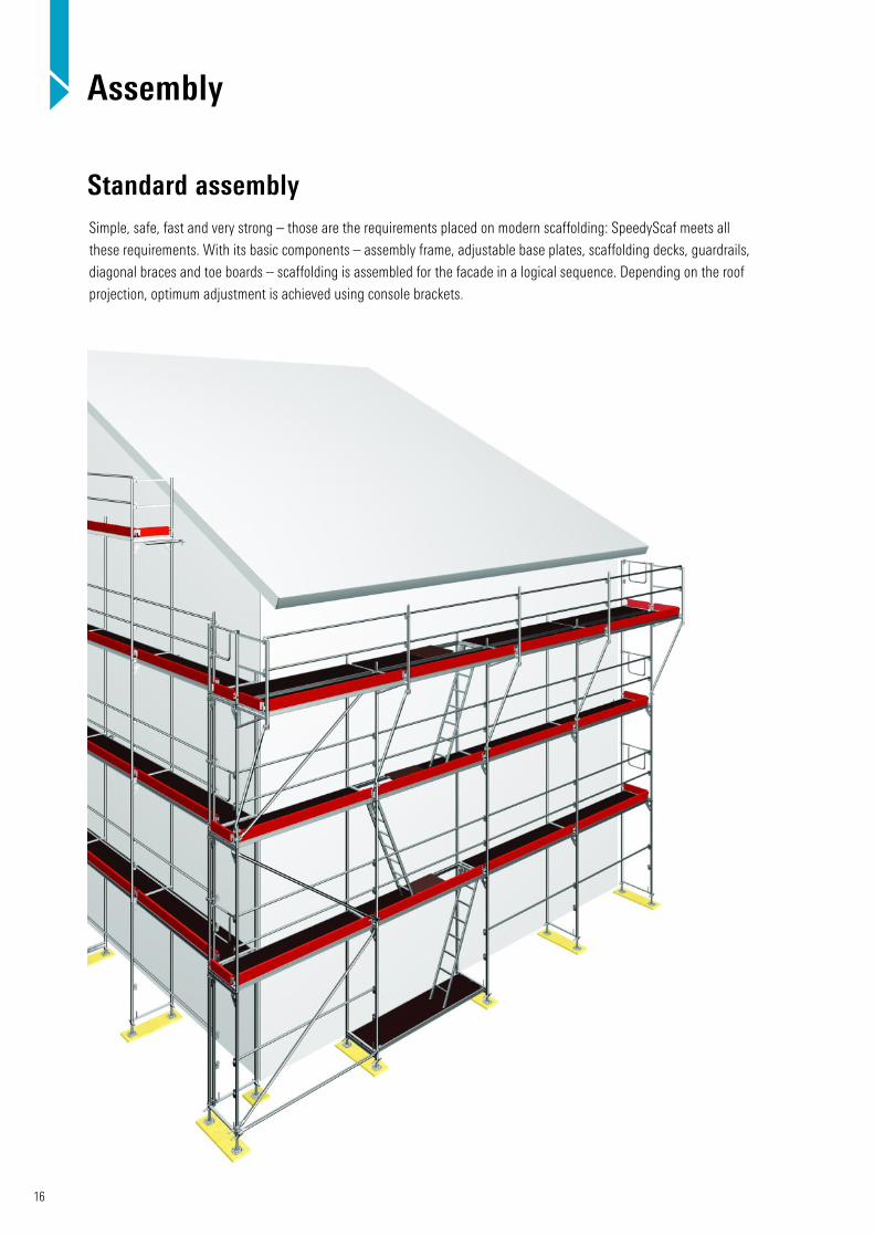
Assembly
Standard assemblySimple, safe, fast and very strong – those are the requirements placed on modern scaffolding: SpeedyScaf meets all
these requirements. With its basic components – assembly frame, adjustable base plates, scaffolding decks, guardrails,
diagonal braces and toe boards – scaffolding is assembled for the facade in a logical sequence. Depending on the roof
projection, optimum adjustment is achieved using console brackets.

17
Gable scaffoldingAlignment and assembly
Console bracket 0.5 m / 0.73 m
9 By installing 0.5 m (or 0.73 mbrackets with bolted-on spigot),the existing bay width can bereduced by 0.5 m.
7 For gable scaffolding, the middlescaffolding bays (preferably the access bays) are aligned with the ridge.
Further assembly, usually symmetrical,follows on both sides.
The scaffolding is optimally adjustedto the roof angle by appropriateselection of the bay lengths.
Aluminium Bridging-ledger
8 For large roof overhangs, the installation of aluminium bridgingledgers is ideal. Spigots on alu-minium bridging ledgers hold theassembly frames above them andpermit a step-by-step reduction ofthe bay width.
7
8
9a Reduction with 0.5 m bracket.
9b Alternative: Reductionwith 0.73 m bracket andbolted-on spigot for channelsection.
9b9a
9

18
Inside corners12 For a gap-free transition at the corner the frames are positioned flush. In the over-lapping bay, side protection isafforded with a telescopic guard rail or tube and couplers,and with a correspondinglylong toe board.
13 0.36 m bracket on the inside:The corner is closed by thefitting of a corner deck, 0,36 m(special part, Art. No. 0707.308),which helps to maintain the per-missible distance from the wall.
13a View of corner area frombelow.
14 Version with 0.73 m bracketon the outside: If the scaffoldingis widened with a 0.73 m bracketin the closing level, a flat andgap-free transition in the cornerarea is possible in conjunctionwith a 1.57 m long bay fitted atthe end.
14a Version as above,seen from below.
Outside corners
The examples show the standard application. Any length
adjustment needed is performed as shown on page 19.
10 For a gap-free transition at the corner the frames are positioned flush.
10a View from above.
11 Widening at the top level is possible with the use of aswivelling and a fixed brackettogether on one upright tube.This avoids any heightmismatch in the scaffoldingdeck levels.
11a Scaffolding widening,view from below.
Assembly
10
10a
11
11a
12
13
13a
14
14a

19
18 Length adjustment at the scaffolding corner depending on the bay lengths: The scaffolding section with the fitted bay is assembled with the level offset by the deck thickness. The deck of the fitted bay is suspended on one side from the assembly frame and on the other side rests on the deck of thesecond scaffolding section.
Length adjustment
17
Height adjustment
15
16 If an assembly framestandard has to be extended,this is done by connecting asteel scaffolding tube usingtwo swivel couplers with aspacing of at least 50 cm.For permissible loading as a function of the height h see table.
16
Tab. 3 Permissible loading as a function of height h
Height h [m] 0.5 0.7 0.9 1.1
Perm. standard load [kN] 9.7 8.5 7.5 6.6
h
≥ 50 cm
18
17 Length adjustment in the middle of the scaffoldingdepending on bay lengths: The scaffolding is positioned left and right, with the fitted bay in approximately the centre of the scaffolding. In the adjustment bay, lapped steel planks or scaffolding boards are used for the deck, with telescopicguard rail or with tubes and couplers fitted as side protection.
15 In the case of inclined terrain, assembly starts at the highestpoint. In conjunction with adjustment frames – 0.66 m, 1.0 mand 1.5 m – problem-free adjustment of the scaffolding to the lieof the ground is possible. The installation of the swivellingadjustable base 60 is recommended for even transmission of the loads.

20
Anchoring
The anchoring of the scaffolding is in accordance with
building authority approval or with the individual verification
of structural strength or respective to local regulations.
22 SpeedyScaf wall tie and inclined wall tiewith double coupler
20 V-type wall tie with double coupler
21 Wall tie with connector coupler
19 SpeedyScaf wall tie with double coupler
19
21
20
22
In addition to the required number of anchors, particular care
must be taken that the wall inserts used are suitable for the
base material. A pull-out test must be conducted and
recorded in the appropriate form and for the application in
question.

21
23
25
26 Physical tie on steel girder or concrete balustradewith scaffolding tube and double couplers
25 Anchoring with short wall tie
24 Clamping coupler on steel support 23 Allround ledger attached to scaffold with doublecouplers (wedge secures tie in ring)
24
26

22
Scaffolding access27 Internal ladder access 27 For scaffolding access, internal ladder access
(standard solution), access decks with integrated or
separate ladder, or external platform stairs are available.
28 The external platform stair access is the appropriate
alternative when craftsmen of various trades are working
on the scaffolding. Decks are provided in full for the
working platform.
29 The SpeedyScaf stairway tower is the preferred
access to higher working areas.
The stairs are installed in parallel (Fig. 28) or alternating
(Fig. 29) directions, and permit rapid and safe access to
the working area.
Application technology
28 External platform stair access (stairs in parallel direction) 29 SpeedyScaf stairway tower (stairs in alternating direction)

23
31 The deck in the assemblyframe must be secured by alock against lift-off.
32 A fan provides protectionagainst falling objects. The surfaces must be coveredwith system decks.
Brick guards
Brick guards must be used when there is any risk of slipping onthe roof.
Either brick guards or protection nets can be attached to thebrick guard support.
Building offset
30
33
34
0.5 m
Facades with projections can be scaffolded when scaffoldingsections are offset: The last assembly frame of the innerscaffolding section and the first frame of the outer section are 0.5 m apart. In this way the system lengths can be maintained. A bracket of the appropriate width is attached to the last-but-oneassembly frame of the inner scaffolding section. The remaining inner gap between the assembly frame is covered by a lappedsteel plank.
34 Projections, e.g. oriel windows or balconies, are easily provided with scaffolding using brackets of appropriate length. On the projecting sections decks of the required length (max. 4.14 m),cover the space between the brackets.

24
Application technology
35 The assembly frames on the brackets must be secured with locking pins.
37 The side walls of dormers are easily scaffolded usingSpeedyScaf aluminium U-double transoms. Assembly framesfrom the last scaffolding level must be secured with locking pins.
36 Connect lattice girders to the assembly frame and then fastenU transoms (with spigot and half-coupler Art. No. 1766.719) to it.Secure the assembly frames of the last and last-but-one levelsusing locking pins.
38 SpeedyScaf and Allround scaffolding can be combinedthanks to standardized dimensions.
Dormers
Dormers can be quickly and safely scaffolded with
standard material; expensive structures using tubes
and couplers can be dispensed with.
35 36
37 38

25
Birdcage scaffolding Gantry frame
43 Gantry frames are used to construct pedestrian passagewaysunderneath scaffolding. Complete covering with scaffolding decksprotects passers-by. The remaining construction can be continuedwith 0.73 m or 1.09 m wide scaffolding. Stiffening of the gantryframes and anchoring of the scaffolding should be in accordancewith German approval.
0.73 m 1.09 m
39 The SpeedyScaf frame for balustrades in use for a dormer.
Dormers 40
41
42
39
43
40 2 m Speedy Frames for balustrades are available forwork on dormers and walls.
41 The SpeedyScaf bridging ledger (special part Art. No. 0700.367) of 2.57 m or 3.07 m length permits rapid and system-conforming construction of birdcage scaffolding. They offer a full-surface scaffolding deck and a permissible load-bearing capacity of 2.0 kN/m2 over the entire surface.
42 An even and gap-free scaffolding deck surface can be obtainedby placing 15 cm long butt tubes on the spigots of the top assemblyframe. The lattice girders are attached to the butts and to theassembly frame standard using double couplers.
In any case, structural strength verification is required for thesupporting scaffolding underneath. Support and additional bracingmust be provided in accordance with structural requirements andwith local conditions.

26
Dead weights of the scaffolding
Tab. 4 Dead weights of facade scaffolding per scaffolding bay
Dead weights of facade scaffoldingBay height 2.00 m
Bay length
2,07 m 2,57 m 3,07 m
per level and standard per m2
visiblearea*
per level and standard per m2
visiblearea*
per level and standard per m2
visiblearea*
Deck/system Width Inner standard gi
Outer standard ga
Inner standard gi
Outer standard ga
Inner standard gi
Outer standard ga
[kg] [kg] [kg/m2] [kg] [kg] [kg/m2] [kg] [kg] [kg/m2]
SpeedyScaf, steel 0.73 m
Robust deck 0.61 m 21.5 36.9 8.9 23.5 42.6 8.3 25.8 48.5 7.9
Robust deck 0.32 m 24.8 40.2 9.7 28.0 47.1 9.1 29.3 52.0 8.5
Steel deck 0.32 m 28.7 44.1 10.6 32.0 51.1 9.9 35.5 58.2 9.5
Stalu deck 0.61 m 20.9 36.3 8.8 22.5 41.6 8.1 24.1 46.8 7.6
Stalu deck 0.32 m 22.5 37.9 9.1 24.6 43.7 8.5 26.6 49.3 8.0
Solid wood deck 0.32 m 26.8 42.2 10.2 32.8 51.9 10.1 38.2 60.9 9.9
EuroSpeedy, steel 0.73 m
Robust deck 0.61 m 20.2 35.6 8.6 22.2 41.3 8.0 24.5 47.2 7.7
Robust deck 0.32 m 23.5 38.9 9.4 26.7 45.8 8.9 28.0 50.7 8.3
Steel deck 0.32 m 27.4 42.8 10.3 30.7 49.8 9.7 34.2 56.9 9.3
Stalu deck 0.61 m 19.7 35.1 8.5 21.3 40.4 7.8 22.8 45.5 7.4
Stalu deck 0.32 m 21.2 36.6 8.8 23.3 42.4 8.2 25.3 48.0 7.8
Solid wood deck 0.32 m 25.5 40.9 9.9 31.5 50.6 9.8 36.9 59.6 9.7
Euro Speedy, aluminium 0.73 m
Robust deck 0.61 m 15.1 25.3 6.1 17.1 30.3 5.9 19.4 34.7 5.6
Robust deck 0.32 m 18.4 28.6 6.9 21.6 34.8 6.8 22.9 38.2 6.2
Stalu deck 0.61 m 14.6 24.8 6.0 16.2 29.4 5.7 17.7 33.0 5.4
Stalu deck 0.32 m 16.1 26.3 6.3 18.2 31.4 6.1 20.2 35.5 5.8
SpeedyScaf, steel 1.09 m
Steel deck 0.32 m 39.2 56.8 13.7 44.1 65.5 12.7 49.4 74.3 12.1
Deck frame + deck 1.00 m 42.0 59.7 14.4 51.6 73.0 14.2 54.4 79.4 12.9
* for the outer standard row
1) Toe board can beincluded in computation
2) AB = deck surface
Tab. 5 Scaffolding groups as per DIN 4420 / HD 1000
Scaffoldinggroup
Fig. 1 Fig. 2
Scaffolding groupevenly distributed
load p
Conc. loadp1
0.5 x 0.5 m
Conc. loadp2
0.2 x 0.2 m
Partial area load Minimum width ofdeck surface
pc Partial area
[kN/m2] [kN] [kN] [kN/m2] [m2] [m]1 0.75 1.50 1.00 not required 0.501)
2 1.50 1.50 1.00 not required 0.601)
3 2.00 1.50 1.00 not required 0.601)
4 3.00 3.00 1.00 5.00 (0.4 x AB)2) 0.90
5 4.50 3.00 1.00 7.50 (0.4 x AB)2) 0.90
6 6.00 3.00 1.00 10.00 (0.5 x AB)2) 0.90
perm. bend
perm. f {
≥ 0.20
≤ l / 100≤ 2.50 cm
III
Pc
b
P
b
f
Fig. 1 Fig. 2

27
Erection height on cantilever brackets
Tab. 6a Steel SpeedyScaf 0.73 m with 0.73 m bracket, scaffolding group 3: 2.0 kN/m2
Type of strengthening Diagonal brace with swivel couplers, with section brace
Deck Steel deck Alu deck, perforated
Robust deck Solid woodframe board
Bay width [m] 2.57 3.07 2.57 3.07 2.57 3.07 2.57 3.07
Number of levels 4 3 5 3 5 3 4 2
Type of strengthening Scaffolding tube diag. brace with double couplers + longitudinal tube
Deck Steel deck Alu deck, perforated
Robust deck Solid woodframe board
Bay width [m] 2.57 3.07 2.57 3.07 2.57 3.07 2.57 3.07
Number of levels 11 9 14 11 14 11 11 8
Type of strengthening Scaffolding tube diagonal brace with double coupler+ outer coupler + longitudinal tube
Deck Steel deck Alu deck, perforated
Robust deck Solid woodframe board
Bay width [m] 2.57 3.07 2.57 3.07 2.57 3.07 2.57 3.07
Number of levels 22 19 27 23 28 23 21 17
Tab. 6b Steel SpeedyScaf 1.09 m with 1.09 m bracket, scaffolding group 4: 3.0 kN/m2
Type of strengthening Scaffolding tube diag. brace with double coupler + longitudinal tube
Deck Steel deck Solid wood frameboard
Deck frame withwood deck
Bay width [m] 2.57 3.07 2.57 3.07 2.57 3.07
Number of levels 3 – 2 – 2 –
Type of strengthening Scaffolding tube diagonal brace with double coupler+ outer coupler + longitudinal tube
Deck Steel deck Solid wood frameboard
Deck frame withwood deck
Bay width [m] 2.57 3.07 2.57 3.07 2.57 3.07
Number of levels 9 9 8 4 8 5
For scaffolding group 3, the following applies:
Z = D = Qa x 0.73 / 2 = kN
Qa = Ga + Pa = kN
Pa1) = 2.4 kN for L3) = 2.57m
Pa1) = 2.8 kN for L3) = 3.07m
Ga = ga x n
For scaffolding group 4, the following applies:
Qa = Ga + Pa = kN
Pa2) = 3.6 kN for L3) = 2.57m
Pa2) = 4.2 kN for L3) = 3.07m
Ga = ga x n
ga as per table page 26
n number of levels on thebracket
1) Pa useful load (2.0 kN/m2) from loading on 1.5 levels
2) Pa useful load (3.0 kN/m2) from loading on 1.5 levels
3) L bay widthThe anchoring and the scaffolding underneath the bracket must in any case be structurally verified.
* The calculated anchor forces result solely from the vertical load, withoutthe additional influence of the wind load. Wind loadings alsohave to be considered.
Calculating the anchor forces*(working loads)
– simplified verification
Qi
Z
D
Qa

28
Application technology
Bridging with framework structure
Gable bridging with 0.45 m or 0.75 m lattice girder
Tab. 7a Lattice girder 0.45 m / 0.75 m
Steel lattice girder 0.45 mwith type-testing
Heavy-duty lattice girder
0.75 m
Spacing c [m] of lateralcompression chord support
1.2 1.3
Number of levelsas a function of the span llattice girder 1)
l = 8.0 m (3 x 2.57 m)
14 20
l = 10.5 m(4 x 2.57 m)
3 12
Live load 2.0 kN/m2 on 1.5 levels
Lattice girder anchoring every 2.57 m
Scaffolding anchoring according to approval
Cable routing on SpeedyScaf scaffolding system 70 steel
Tab. 7b Framework bridging
Span [m]
12.85 15.42 17.99 20.56
Spacing c [m] of lateralcompression chord support
1.2 m 1.2 m 1.2 m 1.2 m
Number of levels 1) 16 10 6 4
Supporting force of lattice girder [kN] (working load)
28.5 24.9 22.0 21.2
Live load 2.0 kN/m2 on 1.5 levels
Lattice girder anchoring / top chord
every 2.57 m
Scaffolding anchoring according to approval
2 lattice girders must be connected at their top chord with swivel couplers, and at the bottomchord with 1 m tubes and double couplers.
Cable/line weight approx. 15 kg/m. Spread approx. 8 kNof ballast provided by others oneach side of the road. Secureframe joints with locking pins.
Max. 11 m
ca. 4
.70
m
1) Above the bridging.2) The scaffolding underneath the bridging must be design checked.
c c
c c
Detail A
Section I– I
Version with type-tested steel lattice girders 0.45 m.1) Above the bridging.2) The scaffolding underneath the bridging must be design checked.
All connections as per details A and B with double and outer coupler.
A B
Detail B
≈ 1,80 m
I I
44
45
46

29
Removal or attachment of scaffolding bays
The Alu Stage 600 with a max. length of 10 m is used for bridging in work* 47 and safety 48 scaffolding structures. With a permissible loading capacity of 2.0 kN/m2 upto 7 m and 1.5 kN/m2 up to 10 m length it meets all the requirements placed on work andsafety scaffolding. Up to 9.15 m length the staging is also available as a folding variant.
* If only the top layer of the work scaffolding is used, the toe boards can be dispensed with in the lower levels;comply to local regulations.
48a Attachment of the brick guard support.
48b Alu stages are secured withsquared-timber couplers againstshifting and tilting.
Alu Stage 60047 48 48a
48b 48a
48b
With SpeedyScaf, it is easy to attach or remove individual scaffolding bays. Thescaffolding frame is, once the deck has been slightly lifted � tilted slightly outwards �and the deck to be removed is, while still suspended on the other side � set down on the existing scaffolding deck �. The deck can now be simply detached (Fig. 49d).Attachment is in the reverse sequence.
49a 49b 49c
49d
�
�
�
�
30
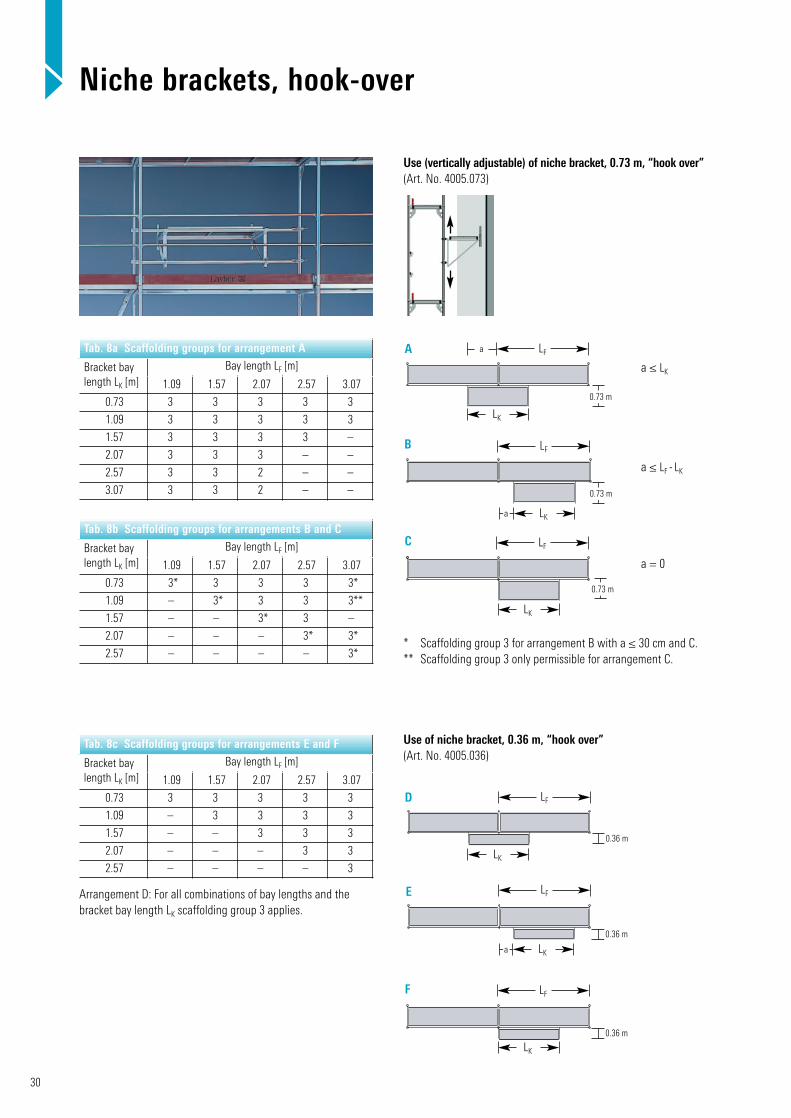
Use of niche bracket, 0.36 m, “hook over”(Art. No. 4005.036)
Tab. 8c Scaffolding groups for arrangements E and F
Bracket baylength LK [m]
Bay length LF [m]
1.09 1.57 2.07 2.57 3.07
0.73 3 3 3 3 3
1.09 – 3 3 3 3
1.57 – – 3 3 3
2.07 – – – 3 3
2.57 – – – – 3
Arrangement D: For all combinations of bay lengths and the bracket bay length LK scaffolding group 3 applies.
D
E
F
LF
LF
LF
LK
LK
LK
a
0.36 m
0.36 m
0.36 m
Niche brackets, hook-over
Tab. 8a Scaffolding groups for arrangement A
Bracket baylength LK [m]
Bay length LF [m]
1.09 1.57 2.07 2.57 3.07
0.73 3 3 3 3 3
1.09 3 3 3 3 3
1.57 3 3 3 3 –
2.07 3 3 3 – –
2.57 3 3 2 – –
3.07 3 3 2 – –
Tab. 8b Scaffolding groups for arrangements B and C
Bracket baylength LK [m]
Bay length LF [m]
1.09 1.57 2.07 2.57 3.07
0.73 3* 3 3 3 3*
1.09 – 3* 3 3 3**
1.57 – – 3* 3 –
2.07 – – – 3* 3*
2.57 – – – – 3** Scaffolding group 3 for arrangement B with a ≤ 30 cm and C.** Scaffolding group 3 only permissible for arrangement C.
a ≤ LK
a = 0
a ≤ LF - LK
A
B
LF
LF
LF
LK
LK
LK
a
a
0.73 m
0.73 m
0.73 m
C
Use (vertically adjustable) of niche bracket, 0.73 m, “hook over” (Art. No. 4005.073)

31
LF
LF
LF
LK
LK
LK
a
0.36 m
0.36 m
0.36 m
Tab. 8f Scaffolding groups for arrangements K and L
Bracket baylength LK [m]
Bay length LF [m]
1.09 1.57 2.07 2.57 3.07
0.73 3 3 3 3 3
1.09 – 3 3 3 3
1.57 – – 3 3 3
2.07 – – – 3 3
2.57 – – – – 3
Arrangement J: For all combinations of bay lengths and the bracket bay length LK scaffolding group 3 applies.
J
K
L
Use of niche bracket, 0.36 m, “curved”(Art. No. 4006.036)
Niche brackets, curved
Tab. 8d Scaffolding groups for arrangement G
Bracket baylength LK [m]
Bay length LF [m]
1.09 1.57 2.07 2.57 3.07
0.73 3 3 3 3 3
1.09 3 3 3 3 3
1.57 3 3 3 2 –
2.07 3 3 2 – –
2.57 3 2 1 – –
3.07 2 1 1 – –
Tab. 8e Scaffolding groups for arrangements H and I
Bracket baylength LK [m]
Bay length LF [m]
1.09 1.57 2.07 2.57 3.07
0.73 3 3 3 3 3*
1.09 – 3 3 3 2**
1.57 – – 3 2 –
2.07 – – – 3 –
2.57 – – – – 2* Scaffolding group 3 for arrangement H with a ≤ 40 cm and I.** Scaffolding group 2 only permissible for arrangement I.
a ≤ LK
a = 0
a ≤ LF - LK
LF
LF
LF
LK
LK
LK
a
a
0.73 m
0.73 m
0.73 m
G
H
I
Use of niche bracket, 0.73 m, “curved” (Art. No. 4006.073)

H
a
L
L ≥ a
32
50a Tube raker50b Second scaffolding
section as buttress50c Projecting scaffolding bay
as buttress
Freestanding scaffolding
Tab. 9 Basic rules for erection
In the open H–a ≤ 3–1
Hmax. = 12 m
In closed areas H–a ≤ 4–1
Hmax. = 20 m
Freestanding scaffolding is required when it cannot or
may not be anchored to the facade.
Here the basic rules of standard DIN 4420, Section 5.4,
must be complied with.
In the open: up to a maximum platform height of 12 m
the ratio of height to smallest base side length must not
exceed 3:1.
In closed areas: up to a platform height of 20 m the ratio
of height to smallest base side length must not exceed 4:1.
The ratios quoted apply only for scaffolding
with steel assembly frames.
50a
51
50b
50c
50c
Plan view
Section

33
x = not permissibleThe relevant safety rules must be complied with.
Rolling towers as per DIN 4420
Rolling towers made of SpeedyScaf parts are assembled
with steel or aluminium assembly frames,
� by connecting together assembly frames using swivel
couplers, or alternatively with tubes and couplers
� by connecting together assembly frames
with lattice girders
� by using mobile beams (Art. No. 1338.320)
The permissible erection heights and any ballast
necessary must be taken into account.
Tab. 10 Required number of ballast weights of 10 kg each
Platform height [m]
6.5 8.5 10.5
In closed areascentral lateral
02
06
010
In the opencentrallateral
010
xx
xx
52c Two scaffolding sectionsconnected by lattice girders, tubes and couplers
52d Scaffolding with mobile beam 3.2 m, adjustable (Art. No. 1338.320) and spigot,adjustable (Art. No. 1337.000).
52b Two scaffolding sectionsconnected by tubes andcouplers.
52a
52b 52c 52d
52a One-sided ortwo-sided wideningwith an assemblyframe and swivelcouplers.