Embed Size (px)
Citation preview

Pub. 43004-025G
G A I - T R O N I C S ® C O R P O R A T I O N A H U B B E L L C O M P A N Y
Model ICP9000 Navigator Series Console Operator’s Manual
04/15 Publication 43004-025G i
CONFIDENTIALITY NOTICE
This manual is provided solely as an operational, installation, and maintenance guide and contains sensitive business and technical information that is confidential and proprietary to GAI-Tronics. GAI-Tronics retains all intellectual property and other rights in or to the information contained herein, and such information may only be used in connection with the operation of your GAI-Tronics product or system. This manual may not be disclosed in any form, in whole or in part, directly or indirectly, to any third party.
COMPUTER SOFTWARE COPYRIGHTS
This product contains copyrighted computer programs stored in semiconductor memory. These programs are copyrighted by GAI-Tronics and may not be reproduced in any form without express written permission from GAI-Tronics.
WARRANTY GAI-Tronics warrants for a period of one (1) year from the date of shipment, that any GAI-Tronics equipment supplied hereunder shall be free of defects in material and workmanship, shall comply with the then-current product specifications and product literature, and if applicable, shall be fit for the purpose specified in the agreed-upon quotation or proposal document. If (a) Seller’s goods prove to be defective in workmanship and/or material under normal and proper usage, or unfit for the purpose specified and agreed upon, and (b) Buyer’s claim is made within the warranty period set forth above, Buyer may return such goods to GAI-Tronics’ nearest depot repair facility, freight prepaid, at which time they will be repaired or replaced, at Seller’s option, without charge to Buyer. Repair or replacement shall be Buyer’s sole and exclusive remedy, and the warranty period on any repaired or replacement equipment shall be one (1) year from the date the original equipment was shipped. In no event shall GAI-Tronics’ warranty obligations with respect to equipment exceed 100% of the total cost of the equipment supplied hereunder. The applicability of any such third-party warranty will be determined solely by GAI-Tronics.
Services. Any services GAI-Tronics provides hereunder, whether directly or through subcontractors, shall be performed in accordance with the standard of care with which such services are normally provided in the industry. If the services fail to meet the applicable industry standard, GAI-Tronics will, for a period of one (1) year from the date of completion, re-perform such services at no cost to the Buyer. Re-performance of services shall be Buyer’s sole and exclusive remedy, and in no event shall GAI-Tronics’ warranty obligations with respect to services exceed 100% of the total cost of services provided hereunder.
Limitations/Exclusions. The warranty on any equipment supplied hereunder is subject to Customer’s use in compliance with applicable FCC regulations and manufacturer specifications. The warranties herein shall not apply to, and GAI-Tronics shall not be responsible for, any damage to the goods or failure of the services supplied hereunder, to the extent caused by accident, misuse, abuse, neglect, system design, product modification, failure to follow instructions contained in the product manual, repair, or attempted repair by anyone not authorized by GAI-Tronics, improper installation, installation of parts that do not conform to the quality or specifications of the original parts or accessories, damage or loss occurred during shipment, or any unit which is not new when sold or upon which the serial number has been defaced, modified or removed. The warranty does not extend to damage incurred by natural causes including Force Majeure. The warranty does not cover microprocessors if failure is due to static damage or application of improper voltage. THE WARRANTIES AND REMEDIES CONTAINED HEREIN ARE IN LIEU OF AND EXCLUDE ALL OTHER WARRANTIES AND REMEDIES, WHETHER EXPRESS OR IMPLIED BY OPERATION OF LAW OR OTHERWISE, INCLUDING ANY WARRANTIES OF MERCHANTABILITY OR FITNESS FOR A PARTICULAR PURPOSE.
Operational and Maintenance Procedures. Buyer acknowledges that any improper use, maintenance, or modification of the equipment provided hereunder, or use of unqualified maintenance or service technicians will severely impair the operational effectiveness of the entire communication system. Buyer hereby agrees to indemnify, defend and hold GAI-Tronics harmless from and against any and all third party claims arising, in any manner, out of: (a) Buyer’s neglect of the equipment; (b) Buyer’s use of technicians not authorized by GAI-Tronics to service the equipment; or (c) Buyer’s improper use or modification of the equipment or failure to follow the operational and maintenance procedures provided with the equipment.
Limitation of Liability/Damages. In no event (even should circumstances cause the exclusive warranties and remedies set forth in the “Warranty” section to fail of their essential purpose) shall either party be liable for any indirect, incidental, special or consequential damages (including, but not limited to, loss of use, loss of anticipated profits, or damages arising from delay) whether such claims are alleged to have arisen out of breach of warranty, breach of contract, strict or absolute liability in tort, or other act, error or omission, or from any other cause whatsoever, or any combination of the foregoing.
Motorola, STAT-ALERT, and RapidCall are registered trademarks of Motorola Incorporated.
04/15 Publication 43004-025G ii
Table of Contents
FOREWORD ............................................................................................................................................................... 6
SCOPE OF MANUAL .................................................................................................................................................... 7 ORDERING REPLACEMENT PARTS .............................................................................................................................. 7 SERVICE AND REPAIR ................................................................................................................................................. 7 FEATURES OF THE ICP9000 NAVIGATOR SERIES CONSOLE ........................................................................................ 8
GUIDED TOUR ......................................................................................................................................................... 11
GRAPHICAL USER INTERFACE (GUI) OVERVIEW AND LAYOUT ................................................................................ 11 LEFT- AND RIGHT-HAND CONFIGURATION ............................................................................................................... 12 THE NAVIGATOR TOOLBAR ...................................................................................................................................... 12 VISIBLE INDICATORS ................................................................................................................................................ 12 AUDIBLE INDICATORS .............................................................................................................................................. 12 THE INFORMATION WINDOW.................................................................................................................................... 13 VU METER ............................................................................................................................................................... 13 CLOCK AND CALENDAR ........................................................................................................................................... 13 USING AUDIO ACCESSORIES ..................................................................................................................................... 14 AUTO-REPEAT BUTTONS .......................................................................................................................................... 14
NAVIGATOR CONFIGURATION ......................................................................................................................... 15
CUSTOMIZING THE NAVIGATOR DESKTOP ................................................................................................................ 15 ADMINISTRATOR LOG ON ........................................................................................................................................ 15 MENU FUNCTIONS .................................................................................................................................................... 16
File Open ............................................................................................................................................................ 16 File Save ............................................................................................................................................................. 17 File Exit .............................................................................................................................................................. 17 Setup - Select Com Port ...................................................................................................................................... 17 Setup - Configure Database ................................................................................................................................ 18 Setup - Audio Options ......................................................................................................................................... 18 Setup - Operator Setup ....................................................................................................................................... 19 Setup - Control Setup .......................................................................................................................................... 22 Setup - Card Suite File ........................................................................................................................................ 23 Tools – Error Log ............................................................................................................................................... 23 Tools - Options – Create Profile ......................................................................................................................... 24 Tools - Options - Save Profile ............................................................................................................................. 25 Tools - Reset Console.......................................................................................................................................... 25 Logon .................................................................................................................................................................. 25 Diagnostics ......................................................................................................................................................... 26 Window - Organize ............................................................................................................................................. 26
STANDARD FEATURE OPERATION .................................................................................................................. 27
SELECTED AND UNSELECTED CHANNELS ................................................................................................................. 27 THE ROLL UP BUTTON ........................................................................................................................................... 27 SETTING THE SPEAKER LEVEL .................................................................................................................................. 27 USING THE UNSELECT MUTE FEATURE .................................................................................................................... 28 USING THE SELECT MUTE OVERRIDE FEATURE ....................................................................................................... 28 SETTING THE CHANNEL VOLUME ............................................................................................................................. 28 SELECTING A CHANNEL ............................................................................................................................................ 29 USING THE CALL INDICATOR .................................................................................................................................... 29 USING THE PROGRAMMABLE BUTTONS .................................................................................................................... 29
Channel Mute ...................................................................................................................................................... 29 Channel Frequency Change ............................................................................................................................... 29 Channel Supervisor ............................................................................................................................................. 30 Channel Alert ...................................................................................................................................................... 30 Channel Monitor ................................................................................................................................................. 30
Table of Contents ICP9000 Navigator Series Console Operator’s Manual
04/15 Publication 43004-025G iii
One-Touch Paging .............................................................................................................................................. 30 Wildcard.............................................................................................................................................................. 31
CHECKING CHANNEL ACTIVITY WITH THE MONITOR BUTTON ................................................................................. 31 PARALLEL ACTIVITY ................................................................................................................................................ 32
Parallel Audio ..................................................................................................................................................... 32 Communicating with a Parallel Unit (Intercom) ................................................................................................ 32
TRANSMITTING ON THE SELECTED CHANNEL ........................................................................................................... 33 TRANSMITTING ON ANY CHANNEL (INSTANT TRANSMIT) ........................................................................................ 33 ACTIVATING AN ALERT TONE .................................................................................................................................. 33 MULTI PL ................................................................................................................................................................. 34 FREQUENCY SELECTION ........................................................................................................................................... 34
Basic Frequency Operation ................................................................................................................................ 34 Enhanced Multi-Frequency Operation ............................................................................................................... 35
PAGING ENCODE ...................................................................................................................................................... 36 Entering the Paging Mode .................................................................................................................................. 36 Paging Channel versus Selected Channel .......................................................................................................... 36 Manual Paging ................................................................................................................................................... 37 Quick-Select Paging ........................................................................................................................................... 38 Initiating the Page .............................................................................................................................................. 39 Sequential Channel Specific Group Paging ....................................................................................................... 39 Stack Paging ....................................................................................................................................................... 40 Hot Standby Paging ............................................................................................................................................ 40 One-Touch Paging .............................................................................................................................................. 41 Alert Page ........................................................................................................................................................... 42 Immediate DTMF Paging ................................................................................................................................... 42 Manual Paging Enable/Disable .......................................................................................................................... 42 Auto-Base Station Override ................................................................................................................................ 43 Exiting Paging Mode .......................................................................................................................................... 43
DTMF DECODE ....................................................................................................................................................... 44 MULTI-SELECT ......................................................................................................................................................... 45
Using Multi-Select .............................................................................................................................................. 45 Signaling in Multi-Select .................................................................................................................................... 45 Multi-Select Alert ................................................................................................................................................ 46 Operations of Channel Transmit during Multi-Select Mode .............................................................................. 46
POSITIVE MODE CONTROL/SECURE OPERATION ...................................................................................................... 47 Using Positive Mode Control .............................................................................................................................. 47 Coded Reception Indicator ................................................................................................................................. 47 Secure Operation in Multi-Select ........................................................................................................................ 48
OPTIONS ................................................................................................................................................................... 49
DC REMOTE CONTROL CP0010/XCP0010 .............................................................................................................. 49 Buttons Not Applicable to DC Control ............................................................................................................... 49 Frequency Buttons with DC Control .................................................................................................................. 49 Monitor Button with DC Control ........................................................................................................................ 49
E&M SIGNALING CP0040/XCP0040 ....................................................................................................................... 50 Buttons Not Applicable to E&M Control ............................................................................................................ 50 E&M with Tone Remote Control ......................................................................................................................... 50
SUPERVISORY CONTROL CP0050/XCP0050 ............................................................................................................ 51 Activating Supervisor Control ............................................................................................................................ 51 Supervisory Control Using Multi-Select ............................................................................................................. 51
DIRECT ENHANCED FULL DUPLEX PHONE INTERFACE CP0070/XCP0070 .............................................................. 52 Using the Direct Phone Interface ....................................................................................................................... 52 Auto-Dial and Last Number Redial .................................................................................................................... 53 Answering Incoming Calls .................................................................................................................................. 54 Phone Patch ........................................................................................................................................................ 54
EXTERNAL ENHANCED FULL DUPLEX PHONE INTERFACE CP0060/XCP0060 ......................................................... 55 Using the External Phone Interface .................................................................................................................... 55 Phone Patch with External Phone Interface ....................................................................................................... 55

ICP9000 Navigator Series Console Operator’s Manual Table of Contents
04/15 Publication 43004-025F iv
RADIO PATCH ........................................................................................................................................................... 56 Using Radio Patch .............................................................................................................................................. 56 Signaling in Radio Patch .................................................................................................................................... 56 Radio Patch Alert................................................................................................................................................ 56
OUTPUT CONTROL XCP0600A ................................................................................................................................ 57 MDC1200 STAT-ALERT SIGNALING CP0650/TDN9413A ................................................................................... 58
RapidCall Buttons ............................................................................................................................................... 59 Receiving RapidCall Transmissions ................................................................................................................... 63
CONSOLE DIAGNOSTICS ..................................................................................................................................... 65
ENTERING THE DIAGNOSTIC MODE .......................................................................................................................... 65 USER PARAMETERS MENU ....................................................................................................................................... 66
Side Tone Volume Adjust .................................................................................................................................... 66 Microphone Selection and Sensitivity ................................................................................................................. 67 Printer Error Messages ...................................................................................................................................... 68
SERVICE DIAGNOSTICS ............................................................................................................................................. 68
DEFINITIONS AND ACRONYMS ......................................................................................................................... 69

6 04/15
Foreword
User Instructions (USA) This equipment has been tested and found to comply with the limits for a Class A digital device, pursuant to part 15 of the FCC Rules. These limits are designed to provide reasonable protection against harmful interference when the equipment is operated in a commercial environment. This equipment generates, uses, and can radiate radio frequency energy and, if not installed and used in accordance with the instruction manual, may cause harmful interference to radio communications. Operation of this equipment in a residential area is likely to cause harmful interference in which case the user will be required to correct the interference at his own expense.
This equipment complies with Part 68 of the FCC rules. Located on the equipment is a label that contains, among other information, the FCC registration number and ringer equivalence number (REN). If requested, this information must be provided to the telephone company. The REN is used to determine the quantity of devices that may be connected to the telephone line. Excessive REN’s on the telephone line may result in the devices not ringing in response to an incoming call. In most, but not all areas, the sum of the REN’s should not exceed five (5.0). To be certain of the number of devices that may be connected to the line, as determined by the total REN’s contact the telephone company to determine the maximum REN for the calling area. This equipment cannot be used on the telephone company-provided coin service. Connection to Party Line Service is subject to State Tariffs. If this equipment causes harm to the telephone network, the telephone company will notify you in advance that temporary discontinuance of service may be required. If advance notice isn’t practical, the telephone company will notify the customer as soon as possible. Also, you will be advised of your right to file a complaint with the FCC if you believe it is necessary. The telephone company may make changes in its facilities, equipment, operations, or procedures that could affect the operation of the equipment. If this happens, the telephone company will provide advance notice in order for you to make the necessary modifications in order to maintain uninterrupted service.
If the trouble is causing harm to the telephone network, the telephone company may request you to remove the equipment from the network until the problem is resolved. This equipment uses the following USOC jacks: RJ11C. It is recommended that the customer install an ac surge arrester in the ac outlet to which this device is connected. This is to avoid damaging the equipment caused by local lightening strikes and other electrical surges. This equipment is Hearing-Aid Compatible (HAC). The telephone Consumer Protection Act of 1991 makes it unlawful for any person to use a computer or other electronic device, including fax machines, to send any message unless such message clearly contains in a margin at the top or bottom of each transmitted page or on the first page of the transmission, the date and time it is sent and an identification of the business or other entity, or other individual sending the message and the telephone number of the sending machine or such business, other entity, or individual. (The telephone number provided may not be a 900 number or any other number for which charges exceed local or long-distance transmission charges.)
User Instructions (Canada) CP-01, Issue 8, Part I: Section 14.1 NOTICE: The Industry Canada label identifies certified equipment. This certification means that the equipment meets certain telecommunications network protective, operational and safety requirements as prescribed in the appropriate Terminal Equipment Technical Requirements document(s). The Department does not guarantee the equipment will operate to the user’s satisfaction. Before installing this equipment, users should ensure that it is permissible to be connected to the facilities of the local telecommunications company. The equipment must also be installed using an acceptable method of connection. The customer should be aware that compliance with the above conditions may not prevent degradation of service in some situations. Repairs to certified equipment should be coordinated by a representative designated by the supplier. Any repairs or alterations made by the user to this equipment, or equipment malfunctions, may give the telecommunications company cause to request the user to disconnect the equipment. Users should ensure for their own protection that the electrical ground connections of the power utility, telephone lines and internal metallic water pipe system, if present, are connected together. This precaution may be particularly important in rural areas.
CAUTION Users should not attempt to make such connections themselves, but should contact the appropriate electric inspection authority, or electrician, as appropriate.
CP-01, Issue 8, Part I: Section 14.2 NOTICE: The Ringer Equivalence Number (REN) assigned to each terminal device provides an indication of the maximum number of terminals allowed to be connected to a telephone interface. The termination on an interface may consist of any combination of devices subject only to the requirement that the sum of the Ringer Equivalence Numbers of all the devices does not exceed 5.
ICP9000 Navigator Series Console Operator’s Manual Foreword
7 04/15
Scope of Manual This manual is intended for use by the operator of any of the models of the ICP9000 Navigator Series Console. It contains all operating instructions for the equipment described and is current as of the printing date. For installation and service information, please refer to the ICP9000 Navigator Series Console User and Installation Manual, Pub. 43004-024.
Certain console functions require initial configuration programming, and therefore, references are made in the manual to GAI-Tronics’ CARD Suite software application which is found in the No. XAC4000B Programming Bundle Flash Drive provided with the console. Consult the system supervisor for available features and program settings.
The programming for your console must be completed before operation. Please refer to the ICP9000 Navigator Series Installation and Service manual packaged with the master control unit (MCU) and the CARD Suite’s Online Help for programming information.
How This Manual Is Organized: The Guided Tour provides an overview of the graphical user interface, GUI, of the ICP9000 Navigator Series console and some general information the operator should be familiar with before proceeding to the “Standard Feature Operation” section.
The “Standard Feature Operation” section describes and instructs the operator on the proper use of the standard features of the console. The “Options” section provides user information on DC Control, E&M Control, Enhanced Phone Interface with Radio Patch, and Supervisory Control. A section on “Console Diagnostics” covers user-adjustable settings available to the operator.
Ordering Replacement Parts When ordering replacement parts or requesting equipment information, please include the complete identification number. This applies to all components, kits, and chassis. If the component part number is not known, the order should include the number of the chassis or kit of which it is a part and sufficient description of the desired component to identify it.
Service and Repair Inoperative or malfunctioning equipment should be returned to the factory for repair.
obtain a Return Authorization number, published repair prices, and shipping instructions.
NOTE: A purchase order or credit card number is required prior to processing non-warranty repairs.
Foreword ICP9000 Navigator Series Console Operator’s Manual
04/15 8
Features of the ICP9000 Navigator Series Console
Enhanced multi-tasking operation
Graphical User Interface (GUI) features touch-screen, mouse or wand support
Desktop layout customizable each operator, including right or left-hand operation
Available in 4, 8, and 12-channel control (4 and 8-channel consoles are field expandable)
Accommodates a maximum of 10 consoles per system
Supports Tone, DC, and E&M control types
Includes Paging Encoder for individual, sequential multi-channel group, stack paging and one-touchpaging
DTMF Decode for Automatic Number Identification
16-Frequency control per channel
The 24 programmable buttons allocated as two per channel to support channel functions such as alerttone, frequency change, infinite or timed mute, monitor and supervisor as well as one-touch pagingusing preprogrammed aliases.
Optional full-duplex telephone interface capability
Supports headset, desktop microphone, and footswitch
Allows standard PC applications to capture printer port output for logging
Multiple dispatcher profiles allow custom configuration of channel names, programmable buttons,channel and window positioning and colors and feature restriction
Individual master volume controls for select and unselect speakers
Individual select and unselect volumes per channel
Easy-to-use Windows®-based programming application
VU-meter for receive and transmit audio
12/24-hour clock
Logging recorder output
Custom paging and multiple alert tones

ICP9000 Navigator Series Console Operator’s Manual Foreword
9 04/15
Model Chart The Main Control Unit (MCU) model number, located on the nameplate on the end of the unit (could be the bottom or side, depending on mounting configuration), specifically identifies GAI-Tronics’ equipment. The last two digits in the model number indicate the number of channels available within that specific unit (04A = 4 channels, 08A = 8 channels, 12A = 12 channels). Factory-installed options are identified in the display area of the Navigator PC screen upon the initial application of power.
The following is a list of the ICP9000 Navigator models:
Model Description
ICPN9004A 4-Channel Navigator Series MCU (expandable)
ICPN9008A 8-Channel Navigator Series MCU (expandable)
ICPN9012A 12-Channel Navigator Series MCU
The following options may be ordered pre-installed in your ICP9000 Navigator Series Console:
Options Description
CP0010 DC Control (Order one for each dc channel)
CP0040 E&M Signaling (One option for every four channels – requires CP0050)
CP0050 Supervisory Control
CP0060 External Enhanced Full Duplex Phone Interface
CP0070 Direct Enhanced Full Duplex Phone Interface
CP0650 MDC1200 STAT-ALERT Signaling (Not compatible with Logging Recorder Output Module)
The following features are included in the standard console and are available through either programming selection or direct access:
DTMF Decode
Positive Mode Control
Paging Encode
Multi-Select Option
16-Frequency Capability
Logging Recorder Output
Foreword ICP9000 Navigator Series Console Operator’s Manual
04/15 10
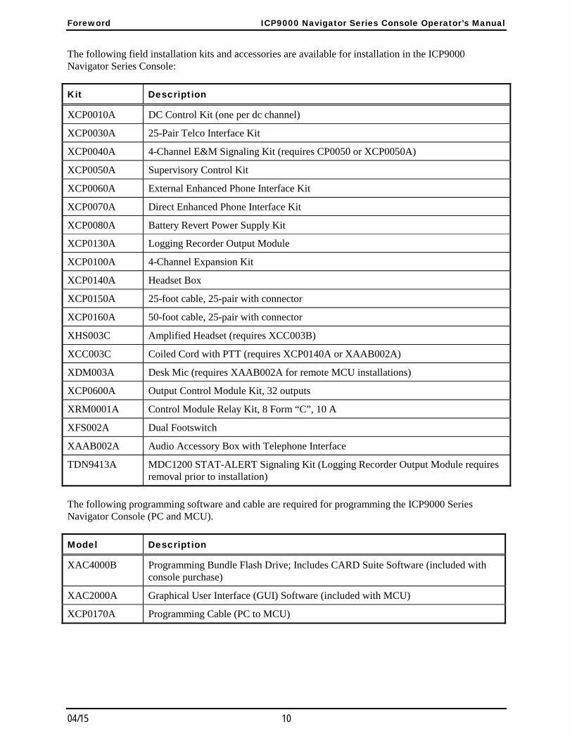
The following field installation kits and accessories are available for installation in the ICP9000 Navigator Series Console:
Kit Description
XCP0010A DC Control Kit (one per dc channel)
XCP0030A 25-Pair Telco Interface Kit
XCP0040A 4-Channel E&M Signaling Kit (requires CP0050 or XCP0050A)
XCP0050A Supervisory Control Kit
XCP0060A External Enhanced Phone Interface Kit
XCP0070A Direct Enhanced Phone Interface Kit
XCP0080A Battery Revert Power Supply Kit
XCP0130A Logging Recorder Output Module
XCP0100A 4-Channel Expansion Kit
XCP0140A Headset Box
XCP0150A 25-foot cable, 25-pair with connector
XCP0160A 50-foot cable, 25-pair with connector
XHS003C Amplified Headset (requires XCC003B)
XCC003C Coiled Cord with PTT (requires XCP0140A or XAAB002A)
XDM003A Desk Mic (requires XAAB002A for remote MCU installations)
XCP0600A Output Control Module Kit, 32 outputs
XRM0001A Control Module Relay Kit, 8 Form “C”, 10 A
XFS002A Dual Footswitch
XAAB002A Audio Accessory Box with Telephone Interface
TDN9413A MDC1200 STAT-ALERT Signaling Kit (Logging Recorder Output Module requires removal prior to installation)
The following programming software and cable are required for programming the ICP9000 Series Navigator Console (PC and MCU).
Model Description
XAC4000B Programming Bundle Flash Drive; Includes CARD Suite Software (included with console purchase)
XAC2000A Graphical User Interface (GUI) Software (included with MCU)
XCP0170A Programming Cable (PC to MCU)
11 04/15
Guided Tour
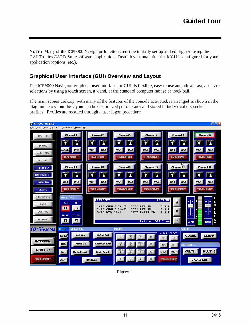
NOTE: Many of the ICP9000 Navigator functions must be initially set-up and configured using the GAI-Tronics CARD Suite software application. Read this manual after the MCU is configured for your application (options, etc.).
Graphical User Interface (GUI) Overview and Layout The ICP9000 Navigator graphical user interface, or GUI, is flexible, easy to use and allows fast, accurate selections by using a touch screen, a wand, or the standard computer mouse or track ball.
The main screen desktop, with many of the features of the console activated, is arranged as shown in the diagram below, but the layout can be customized per operator and stored in individual dispatcher profiles. Profiles are recalled through a user logon procedure.
Figure 1.

Guided Tour ICP9000 Navigator Series Console Operator’s Manual
04/15 12
Left- and Right-Hand Configuration The Navigator can be configured for left- or right-hand configuration to allow the most convenient set-up for each operator. The reference to left or right-hand is related to the location of the main TRANSMIT button. In the following sections, reference to the left or right side of the GUI are made. It is assumed from this point on that the GUI is configured for left-hand operation with the main TRANSMIT button located on the left of the GUI. If the operator configures the GUI for right-hand TRANSMIT operation, the references to left and right should be reversed.
The Navigator Toolbar The Navigator includes a toolbar that can be seen as a vertical column of buttons located on the upper left side of the GUI. These buttons activate and deactivate additional modes of operation for the Navigator. For example, FREQUENCY and PHONE are toolbar buttons that open display windows with additional selectable buttons applicable to that function. Each of the applicable Navigator toolbar buttons is explained in this manual. Some of the toolbar buttons are for optional features that must either be configured through the CARD Suite software application, or purchased separately as options. The toolbar can also be customized for each operator to rearrange the buttons, remove unused buttons, or to restrict access to certain features.
Visible Indicators The Navigator is equipped with many visual indicators that are associated with a button, a function or a status. Indicators can be either the entire button or simply the border of a button. The placement of each indicator intuitively associates the indicator with the proper function or status. The function of each indicator is discussed in the “Standard Feature Operation” section of this manual. It is important that the operator be familiar with each indicator, its function and its effect on the operation of the console in both the active and inactive state.
Audible Indicators There is an audible indicator that indicates the operator has attempted to perform a function or has pressed a button that is prohibited in the current mode of operation, or is not available. To hear this error beep while in normal operation, press the SCROLL Up/Down button to the right of the information window repeatedly until the error beep sounds. Whenever this beep sounds, it indicates that the operator attempted to perform some function that the console would not allow. The operator should examine the console and determine why the beep was generated and become familiar with the proper operation of each button for future use.
There is also a tone generated when the channel volume is changed only when the channel is not receiving audio. This volume beep is generated to allow the operator to adjust the channel volume to a relative setting and is indicative of the level of receive audio.
The operator may hear other tones known as side tone that do not indicate any particular function, but allows the operator to hear tones that are being transmitted by the console or know that digital signaling is being transmitted. These side tones are generated during paging, alert tone and digital signaling generation.
ICP9000 Navigator Series Console Operator’s Manual Guided Tour
13 04/15
The Information Window An important feature of the Navigator desktop is the information window located in the central area of the desktop. At the top of the information window is the status line, which displays information for the selected channel. Below the status line is information that is relevant to the functions that are taking place at the time. To the side of the information window are scroll buttons with up and down arrows and the DEL button. The arrow buttons are used to move through lists. The DEL is used to clear selections and remove decoded DTMF and signaling data from the window.
VU Meter The VU meter appears between the select and unselect volume sliders to the right of the information window. The VU provides an indication of the signal level for transmitted audio during a transmission or intercom, and the signal level of the selected channel receive audio during receive mode. The VU meter should not be used as a measurement device as it is not calibrated. It provides a reference for the operator to know the proper audio is being transmitted or received.
While becoming familiar with the console, the operator should watch the VU for proper and consistent deflection during voice transmissions to ensure that the field units are receiving audible and intelligible audio. If the operator sits too close to the microphone and the VU is deflected fully, the audio heard by the field units may be distorted and unintelligible. Likewise, if the operator is not close enough to the microphone and there is little deflection of the VU meter, the field units may find it difficult to hear the operator over the background noise in the dispatch area. The sensitivity of the microphone can be adjusted for different (loud versus quiet) voice types. Refer to the “Diagnostics” section on page 67 for information on adjustment of the microphone sensitivity.
Clock and Calendar The clock located above the GAI-Tronics logo provides the current PC time. Passing the pointer or touching the clock provides a momentary pop-up indicating the calendar. The clock and format are set through the Windows® operating system. If a network clock source is available to synchronize the clock to a standard time, ask the system supervisor to configure the PC to take advantage of this feature.
Guided Tour ICP9000 Navigator Series Console Operator’s Manual
04/15 14
Using Audio Accessories Certain audio accessories can be connected to the console for use by the operator. These accessories include a desk microphone, a gooseneck microphone, a handset and a footswitch. It is important to understand that the transmit feature of these accessories emulates the main TRANSMIT button, and the MONITOR button of these accessories emulates the main MONITOR button. The same restrictions and applications of these accessory buttons apply as described in the “Standard Feature Operation” section of this manual. Whenever the main TRANSMIT button is referenced in the following sections, it is understood that the operator could use the transmit button of an attached accessory instead. This same understanding also applies to the MONITOR button.
Auto-Repeat Buttons Certain buttons on the console are designed to auto-repeat similarly to that of a computer keyboard. When these buttons are pressed and held, after about a 1-second delay, the button begins to auto-repeat at about two presses per second. When the key is released, the auto-repeat ceases. The auto-repeat keys include the channel VOLUME Up/Down and the SCROLL Up/Down.
15 04/15
Navigator Configuration
Customizing the Navigator Desktop The Navigator offers great flexibility in customizing the layout to suit each operator. Customization allows the following:
The boarder of each channel can be color-coded per operator to group similar services.
The channels can be placed in the channel area above the information window in any position or order per operator to ease use and to reduce eye fatigue.
The individual channel selection button labels and their associated programmable button labels are configurable.
The four alert tone button labels are configurable.
The toolbar buttons can be reordered or even removed per operator.
The assignment and order of available paging aliases per operator.
Access to certain features can be restricted by removing menu bar items per operator.
The application can be configured per operator to prevent exiting the Navigator and to restrict access to other windows programs and display settings.
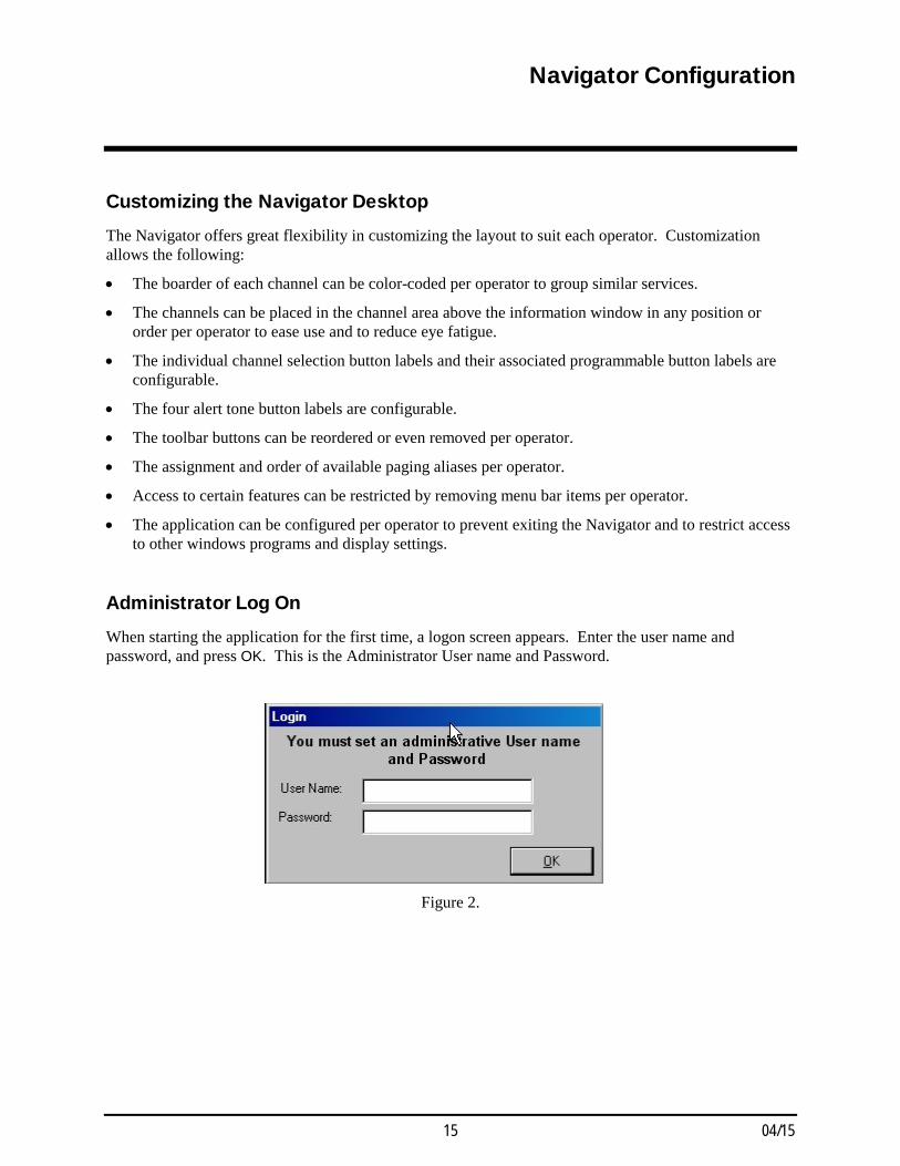
Administrator Log On When starting the application for the first time, a logon screen appears. Enter the user name and password, and press OK. This is the Administrator User name and Password.
Figure 2.
Navigator Configuration ICP9000 Navigator Series Console Operator’s Manual
04/15 16
Menu Functions
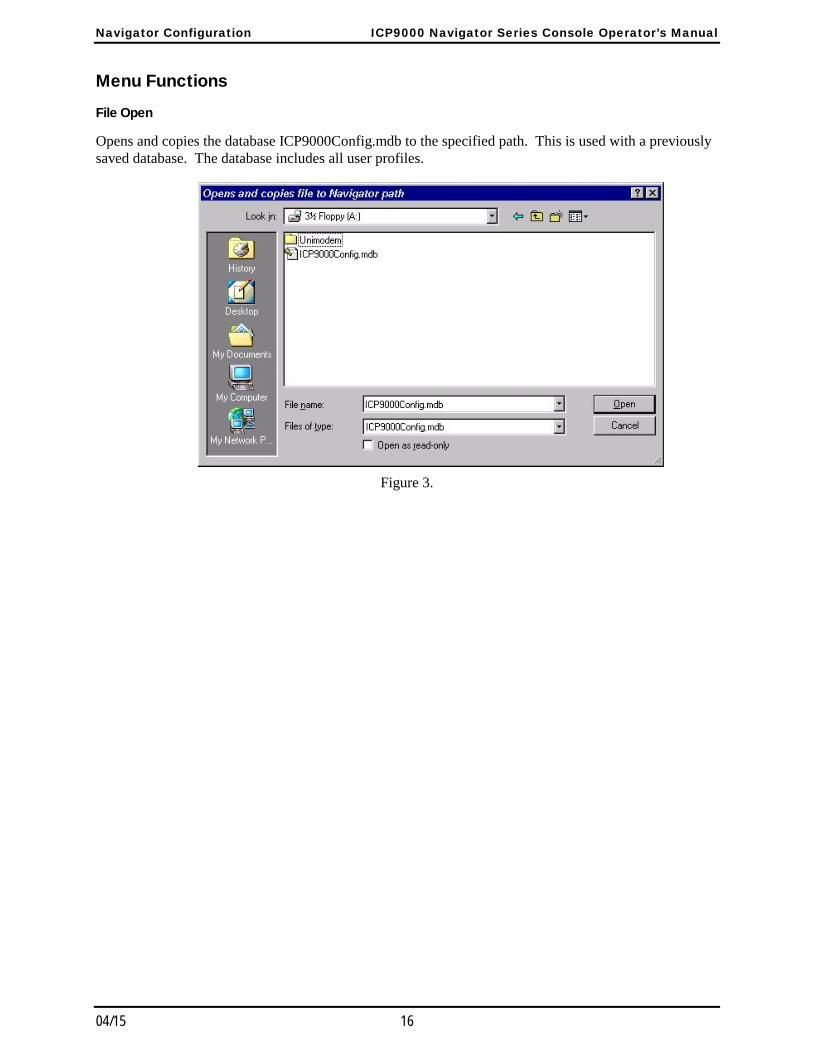
File Open
Opens and copies the database ICP9000Config.mdb to the specified path. This is used with a previously saved database. The database includes all user profiles.
Figure 3.

ICP9000 Navigator Series Console Operator’s Manual Navigator Configuration
17 04/15
File Save
Saves the database to a path determined by the user. Use the Open function to retrieve the originally saved database.
Figure 4.
The above section refers to backing up the profile database.
File Exit
Closes the ICP9000 Navigator GUI application.
Setup - Select Com Port
This selection can be set in the operator setup and should only be enabled only for authorized personnel. This selects the current communications port to connect to the main CPU.
WARNING ALL Communications between the MCU and the PC cease during this selection.
Figure 5.
Navigator Configuration ICP9000 Navigator Series Console Operator’s Manual
04/15 18
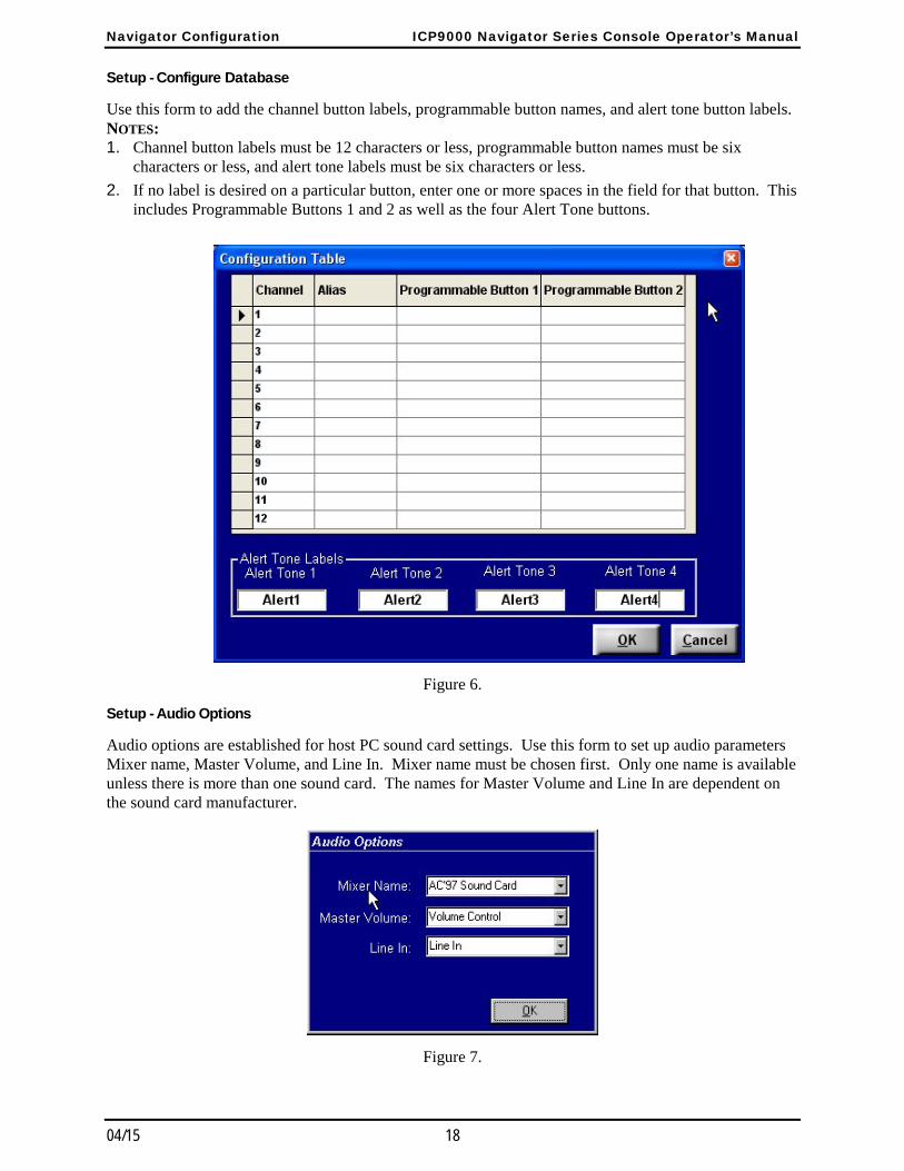
Setup - Configure Database
Use this form to add the channel button labels, programmable button names, and alert tone button labels. NOTES: 1. Channel button labels must be 12 characters or less, programmable button names must be six
characters or less, and alert tone labels must be six characters or less.
2. If no label is desired on a particular button, enter one or more spaces in the field for that button. This includes Programmable Buttons 1 and 2 as well as the four Alert Tone buttons.
Figure 6.
Setup - Audio Options
Audio options are established for host PC sound card settings. Use this form to set up audio parameters Mixer name, Master Volume, and Line In. Mixer name must be chosen first. Only one name is available unless there is more than one sound card. The names for Master Volume and Line In are dependent on the sound card manufacturer.
Figure 7.
ICP9000 Navigator Series Console Operator’s Manual Navigator Configuration
19 04/15
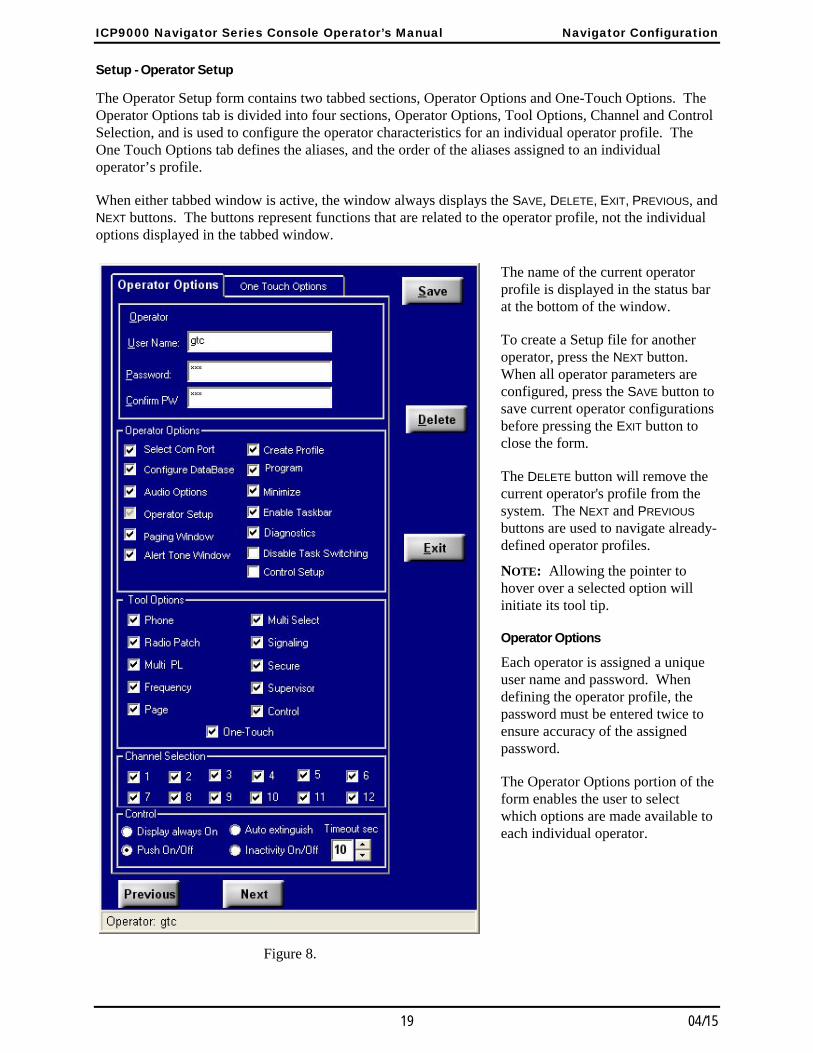
Setup - Operator Setup
The Operator Setup form contains two tabbed sections, Operator Options and One-Touch Options. The Operator Options tab is divided into four sections, Operator Options, Tool Options, Channel and Control Selection, and is used to configure the operator characteristics for an individual operator profile. The One Touch Options tab defines the aliases, and the order of the aliases assigned to an individual operator’s profile.
When either tabbed window is active, the window always displays the SAVE, DELETE, EXIT, PREVIOUS, and NEXT buttons. The buttons represent functions that are related to the operator profile, not the individual options displayed in the tabbed window.
The name of the current operator profile is displayed in the status bar at the bottom of the window.
To create a Setup file for another operator, press the NEXT button. When all operator parameters are configured, press the SAVE button to save current operator configurations before pressing the EXIT button to close the form.
The DELETE button will remove the current operator's profile from the system. The NEXT and PREVIOUS buttons are used to navigate already-defined operator profiles.
NOTE: Allowing the pointer to hover over a selected option will initiate its tool tip.
Operator Options
Each operator is assigned a unique user name and password. When defining the operator profile, the password must be entered twice to ensure accuracy of the assigned password.
The Operator Options portion of the form enables the user to select which options are made available to each individual operator.
Figure 8.
Navigator Configuration ICP9000 Navigator Series Console Operator’s Manual
04/15 20
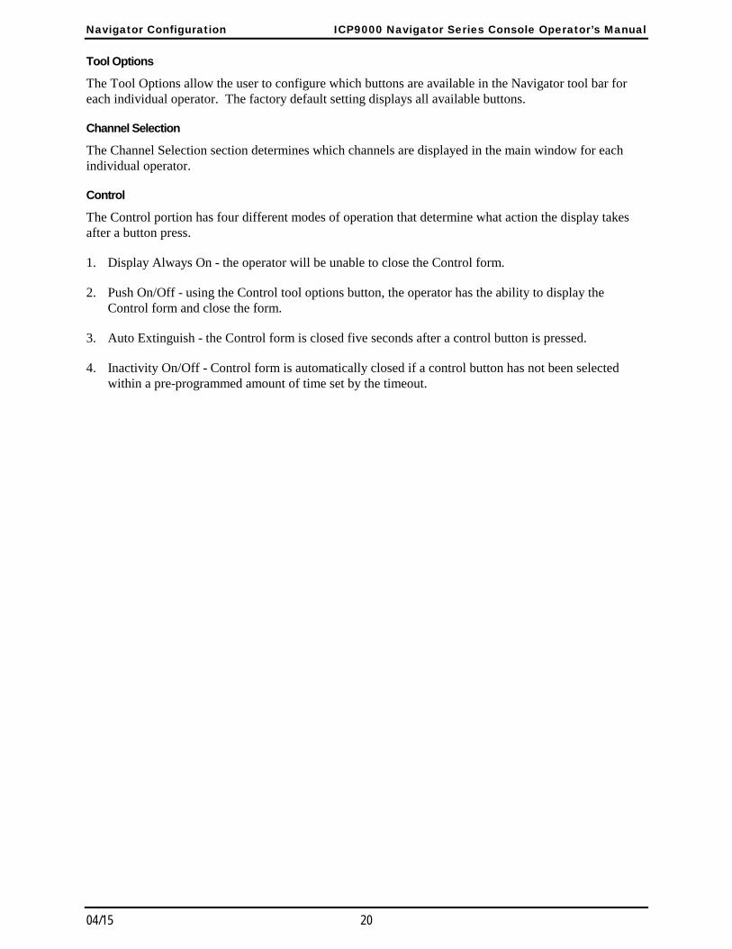
Tool Options
The Tool Options allow the user to configure which buttons are available in the Navigator tool bar for each individual operator. The factory default setting displays all available buttons.
Channel Selection
The Channel Selection section determines which channels are displayed in the main window for each individual operator.
Control
The Control portion has four different modes of operation that determine what action the display takes after a button press.
1. Display Always On - the operator will be unable to close the Control form.
2. Push On/Off - using the Control tool options button, the operator has the ability to display the Control form and close the form.
3. Auto Extinguish - the Control form is closed five seconds after a control button is pressed.
4. Inactivity On/Off - Control form is automatically closed if a control button has not been selected within a pre-programmed amount of time set by the timeout.
ICP9000 Navigator Series Console Operator’s Manual Navigator Configuration
21 04/15
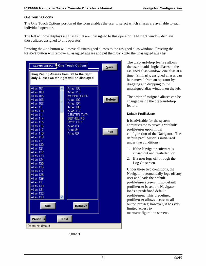
One Touch Options
The One Touch Options portion of the form enables the user to select which aliases are available to each individual operator.
The left window displays all aliases that are unassigned to this operator. The right window displays those aliases assigned to this operator.
Pressing the ADD button will move all unassigned aliases to the assigned alias window. Pressing the REMOVE button will remove all assigned aliases and put them back into the unassigned alias list.
The drag-and-drop feature allows the user to add single aliases to the assigned alias window, one alias at a time. Similarly, assigned aliases can be removed from an operator by dragging and dropping to the unassigned alias window on the left.
The order of assigned aliases can be changed using the drag-and-drop feature.
Default Profile/User
It is advisable for the system administrator to create a “default” profile/user upon initial configuration of the Navigator. The default profile/user is initialized under two conditions:
1. If the Navigator software is closed out and re-started, or
2. If a user logs off through the Log On screen.
Under these two conditions, the Navigator automatically logs off any user and loads the default profile/user screen. If no default profile/user is set, the Navigator loads a predefined default profile/user. This predefined profile/user allows access to all button presses; however, it has very limited access to menu/configuration screens.
Figure 9.
Navigator Configuration ICP9000 Navigator Series Console Operator’s Manual
04/15 22
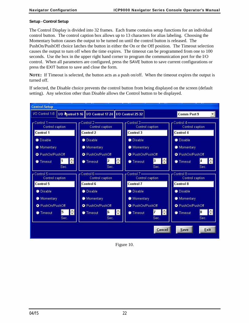
Setup - Control Setup
The Control Display is divided into 32 frames. Each frame contains setup functions for an individual control button. The control caption box allows up to 13 characters for alias labeling. Choosing the Momentary button causes the output to be turned on until the control button is released. The PushOn/PushOff choice latches the button in either the On or the Off position. The Timeout selection causes the output to turn off when the time expires. The timeout can be programmed from one to 100 seconds. Use the box in the upper right hand corner to program the communication port for the I/O control. When all parameters are configured, press the SAVE button to save current configurations or press the EXIT button to save and close the form.
NOTE: If Timeout is selected, the button acts as a push on/off. When the timeout expires the output is turned off.
If selected, the Disable choice prevents the control button from being displayed on the screen (default setting). Any selection other than Disable allows the Control button to be displayed.
Figure 10.
ICP9000 Navigator Series Console Operator’s Manual Navigator Configuration
23 04/15
Setup - Card Suite File
The operator uses this menu item to open a Card Suite configuration file. An existing archive file must be exported from the ICP9000 using the Card Suite software, creating a filename with the .cst extension. The Navigator GUI opens this file, and extracts the paging alias information from the archived data. The paging alias information is used when configuring the available one-touch paging aliases for operator profiles.
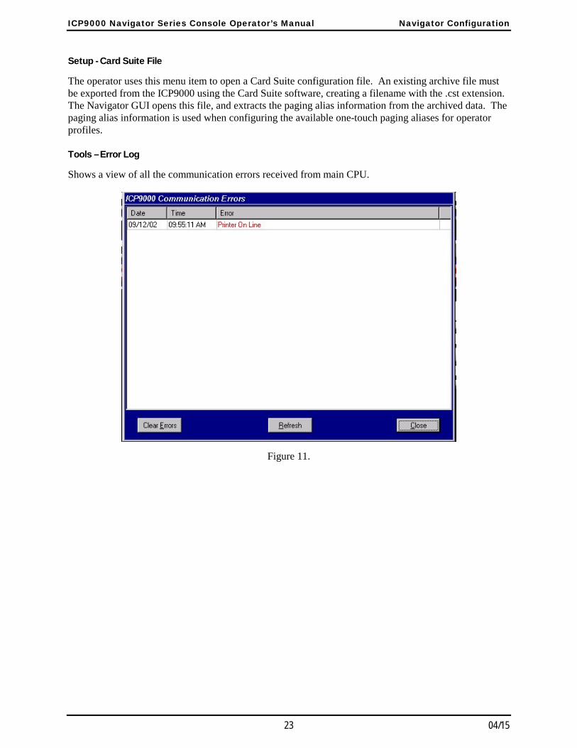
Tools – Error Log
Shows a view of all the communication errors received from main CPU.
Figure 11.
Navigator Configuration ICP9000 Navigator Series Console Operator’s Manual
04/15 24
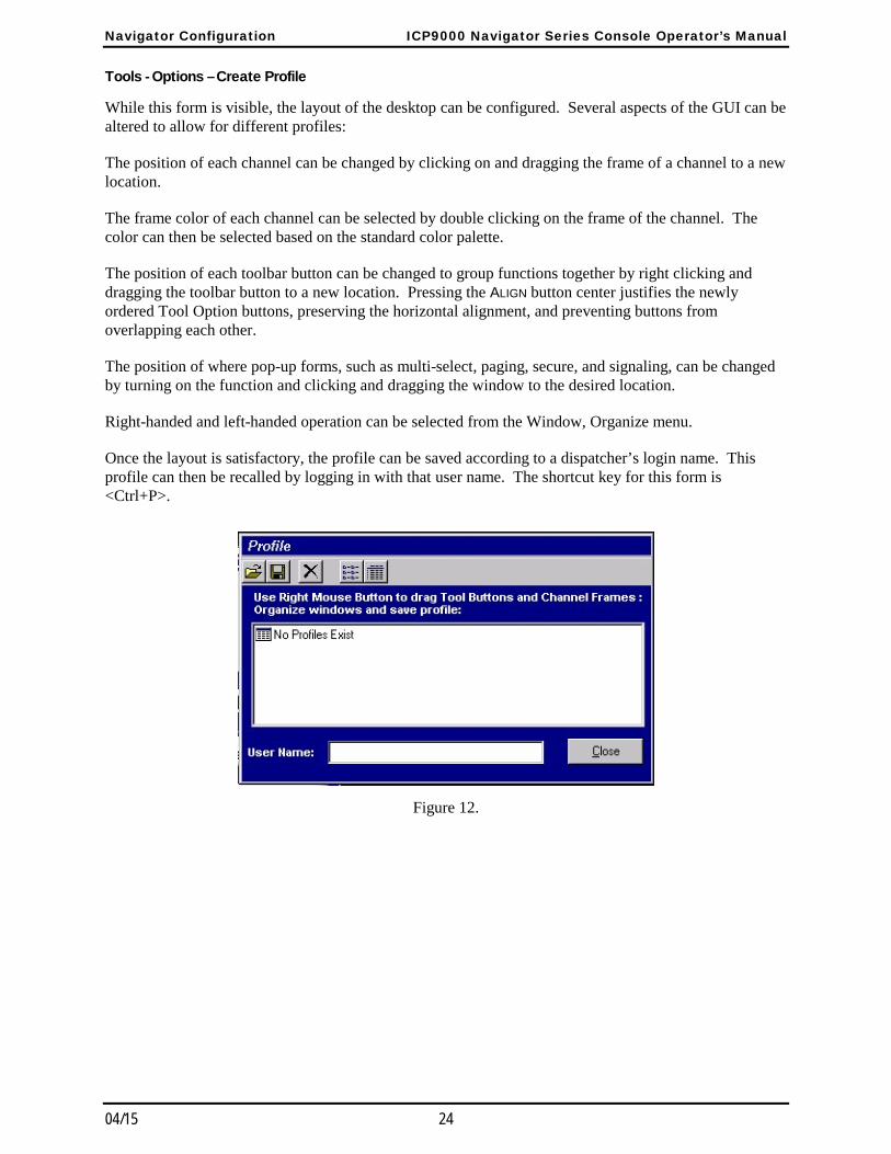
Tools - Options – Create Profile
While this form is visible, the layout of the desktop can be configured. Several aspects of the GUI can be altered to allow for different profiles:
The position of each channel can be changed by clicking on and dragging the frame of a channel to a new location.
The frame color of each channel can be selected by double clicking on the frame of the channel. The color can then be selected based on the standard color palette.
The position of each toolbar button can be changed to group functions together by right clicking and dragging the toolbar button to a new location. Pressing the ALIGN button center justifies the newly ordered Tool Option buttons, preserving the horizontal alignment, and preventing buttons from overlapping each other.
The position of where pop-up forms, such as multi-select, paging, secure, and signaling, can be changed by turning on the function and clicking and dragging the window to the desired location.
Right-handed and left-handed operation can be selected from the Window, Organize menu.
Once the layout is satisfactory, the profile can be saved according to a dispatcher’s login name. This profile can then be recalled by logging in with that user name. The shortcut key for this form is <Ctrl+P>.
Figure 12.
ICP9000 Navigator Series Console Operator’s Manual Navigator Configuration
25 04/15
Tools - Options - Save Profile
Saves settings to the current user logged on. The shortcut key combination is <Ctrl+S>.
Tools - Reset Console
This reboots the console’s MCU.
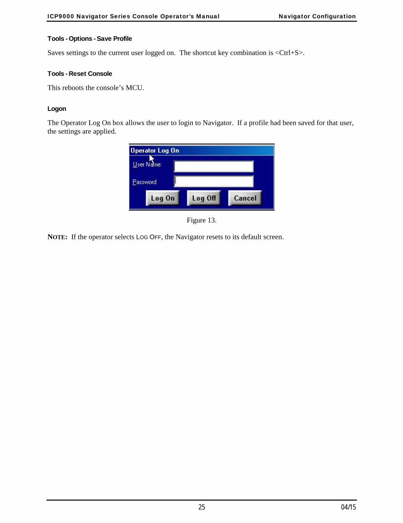
Logon
The Operator Log On box allows the user to login to Navigator. If a profile had been saved for that user, the settings are applied.
Figure 13.
NOTE: If the operator selects LOG OFF, the Navigator resets to its default screen.

Navigator Configuration ICP9000 Navigator Series Console Operator’s Manual
04/15 26
Diagnostics
Opens a window where console diagnostics can be accessed. This screen is password-protected and should only be accessed by authorized personnel.
Window - Organize
Allows the toolbar to be organized for left-hand or right-hand operation.
27 04/15
Standard Feature Operation
Selected and Unselected Channels At any given time, a single channel is designated as the selected channel. Many of the console’s features such as paging, signaling, monitor, alert tone, intercom and the main TRANSMIT button operate on the selected channel. Refer to the status line or top line of the information window located in the center of the desktop for information concerning the selected channel. This information includes the channel’s alias as defined by CARD Suite, channel state, transmit, receive, monitor, intercom, supervisor, and other optional information configured using CARD Suite, such as PL setting and secure state of the channel.
Refer to the “Definitions and Acronyms” section on page 69 for definitions. If a channel is not selected, it is considered unselected. The selected channel’s audio is directed to the select speaker (left channel) and summed audio from all other unselected channels is directed to the unselect speaker (right channel).
In some modes of operation, the SELECT indicator flashes on the selected channel while the SELECT indicator of another channel or other channels is lit steadily. Whenever a SELECT indicator is flashing, it indicates that the console is in a mode of operation where the selected channel is not included. In some of these cases, the selected channel audio is routed to the unselect speaker while the audio of the channel(s) included in the current mode of operations is/are routed to the select speaker. While becoming familiar with the different modes of operation, the operator should note when the SELECT indicator is flashing and take time to understand the behavior of the console when this occurs.
The ROLL UP Button The ROLL UP button allows channels that are not being used to be “rolled-up” so that only the SELECT button of the channel is visible. This may be useful if the channel is needed rarely. To roll up a channel, first press the ROLL UP button and then roll up the desired channels by pressing their SELECT button. The channel can be unrolled in two ways. Activate the roll-up feature by pressing the ROLL UP button and then selecting the desired rolled up channels to be unrolled. A quicker method to unroll a channel is to simply press the SELECT button while in normal operation.
Setting the Speaker Level To the side of the information window are two sliders that adjust the master volume of the select and unselect speakers. The operator should adjust the level of each speaker so that select and unselect audio can be discerned from each other. Passing the pointer over either slider provides a pop-up indicating the current volume setting of the slider.
Standard Feature Operation ICP9000 Navigator Series Console Operator’s Manual
04/15 28
Using the Unselect Mute Feature Since the console uses only two speakers for up to 12 channels, it may sometimes be difficult to hear particular field units in busy or noisy environments. To allow a particular channel to be isolated from all other channels, the unselect mute feature of the console allows all except the selected channel to be muted.
Below the unselect volume slider is a MUTE button. The unselect MUTE button activates the unselect mute feature for 10 seconds (factory default). The MUTE button indicator lights, the unselect volume slider grays out and the unselect speaker volume is attenuated approximately 30 dB. Though greatly attenuated, the unselect audio is still audible if a field unit on an unselected channel requires immediate assistance. Pressing and holding the unselect MUTE button for about one-half second activates the unselect mute indefinitely, and is indicated by a flashing unselect MUTE button. Pressing the unselect MUTE button a second time or adjusting the unselect speaker volume deactivates the unselect mute.
Using the Select Mute Override Feature When a headset is connected or the handset is taken off-hook, the selected channel audio is automatically routed to the handset or headset and the select speaker audio is muted. In this situation, only the operator can hear the selected channel audio. In some situations, a supervisor may want to listen in on a conversation. The console employs a select mute override feature than can be used to unmute the select speaker to allow a supervisor to listen to the current conversation without interfering with the operator’s current set-up.
The select MUTE button is only active when a handset or headset is used. When activated, the select MUTE button indicator lights and the selected channel volume slider is grayed out. To allow the selected channel audio to be heard from either the handset or headset and the select speaker, press the select MUTE button or adjust the select speaker volume slider. To reactivate the select mute, press the select MUTE button again, disconnect and reconnect the headset, or place the handset on and back off-hook.
Setting the Channel Volume The volume sliders on the desktop to the side of the information window adjust the master volume of the select and unselect speakers. Each channel has three volume settings available to adjust the relative level of each channel. Adjusting the relative speaker volume allows the audio level of individual channels to be adjusted for the desired operating environment. These settings remain even if the console is reset or loses power.
When a channel is selected and a headset or handset is in use, pressing the VOL Up/Down buttons adjusts the relative headset or handset volume for the selected channel. If a headset or handset is not in use, pressing the VOL Up/Down on the selected channel adjusts the relative select-channel speaker volume. When a channel is unselected, pressing the VOL Up/Down adjusts the relative unselect-channel speaker volume. When the channel volume is changed, a beep indicative of the new channel volume is heard through the appropriate select or unselect speaker if no receive audio is detected on the channel being adjusted.
If a channel is currently muted using the channel-mute feature, the channel will be unmuted whenever the VOL UP button is pressed on that channel whether it is selected or unselected. If the VOL DOWN button is pressed, the channel will remain muted and the volume will be decreased.
ICP9000 Navigator Series Console Operator’s Manual Standard Feature Operation
29 04/15
Selecting a Channel As described earlier, at any given time during normal operation, one channel is designated as the selected channel. All of the non-channel specific buttons that affect a channel operate on the selected channel. These include the Unselect MUTE, SUPERVISOR, ALERT1 - ALERT4, MULTI-PL, INTERCOM, SECURE, FREQUENCY, MONITOR and TRANSMIT buttons.
To select a channel, press the SELECT button on the desired channel. When the channel is selected the SELECT button lights green. When another channel is selected, the currently selected channel is unselected and the new channel is selected. Depending on the CARD Suite configuration, channels can be disabled or may not be available. An error beep is generated when attempting to select one of these channels.
Using the Call Indicator A red call indicator is provided on each channel to indicate reception of audio on the channel. The border of the SELECT button flashes red when activated. This indicator allows the operator to quickly glance at the console to determine which channel in currently receiving audio.
After audio is no longer detected on the channel, the CALL indicator remains flashing for 2 seconds (factory default). CARD Suite can be used to configure the CALL indicator to flash for a specified time period, or to flash until a transmission is made on the channel. The operator should inquire with the system supervisor about the configured behavior of the CALL indicator.
Using the Programmable Buttons There are two programmable buttons per channel, by default labeled WC1 and WC2, located below the volume buttons on each channel. These buttons may be programmed to perform various operations specific to the channel or for one-touch paging using preprogrammed aliases.
Channel Mute
The channel mute feature allows a channel to be muted at any time during all modes of operation. This may be useful if the reception on a particular channel is interfering with a transmission, or if the operator is attempting to identify on which channel a particular reception is being received.
Using CARD Suite, the channel mute feature can be programmed to mute the channel’s audio indefinitely or for a timed duration. If the mute is indefinite, the border of the channel mute button will flash. If programmed for a timed duration, the border will illuminate. If the operator presses the channel mute button at any time while the channel is muted, the channel’s audio will be unmuted and the border indicator will be extinguished.
Channel Frequency Change
The channel frequency change feature allows the frequency of the channel to be changed on a particular channel at any time while in most modes of operation without first selecting the channel. The border of the channel frequency button will light only when the channel is on the particular frequency associated with that button.
If, for example, the channel has three frequencies enabled and the two programmable buttons are programmed for F1 and F2, the F1 border will light when the channel in on F1. If the channel is on F2, the F2 border will light. If, however, the channel is on F3, neither the F1 nor the F2 border will light. For more information on frequency operation see “Basic Frequency Operation” in the “Frequency Selection” section of this manual.
Standard Feature Operation ICP9000 Navigator Series Console Operator’s Manual
04/15 30
It is not possible to execute a channel frequency change while selecting a radio-patch, multi-select, frequency or multi-PL.
Channel Supervisor
The channel supervisor feature allows supervisor control to be activated or deactivated on a channel at any time in all modes of operation without first selecting the channel. While the channel has supervisor mode activated, the border of the channel supervisor button will light. For more information on supervisor operation, see “Activating Supervisor Control” in the “Options” section of this manual.
Channel Alert
The channel alert feature can be programmed to generate one of the four available alert tones on a particular channel at any time during most modes of operation without first selecting the channel. The channel alert buttons behave exactly like the four alert tone buttons. While the channel alert is activated, the border of the channel alert button will light. To extend the talk-time, press and hold the main TRANSMIT button or the channel’s TRANSMIT button. To end the talk-time, press and release the channel alert, main TRANSMIT or channel TRANSMIT button. For more information on the alert tone feature see Activating an Alert Tone on page 33 in this manual.
It is not possible to execute a channel alert while selecting a radio-patch, multi-select, frequency or multi-PL.
Channel Monitor
The channel monitor feature allows a particular channel to be placed into monitor mode at any time during most modes of operation without first selecting the channel. While the channel is in monitor mode, the border of the channel monitor button will be lit. For more information on monitor operation see “Checking Channel Activity with the Monitor Button” on page 31 in this manual.
It is not possible to execute a channel monitor while selecting a radio-patch, multi-select, frequency or multi-PL.
One-Touch Paging
A one-touch paging alias can be assigned to any programmable button to allow transmission of that paging alias at any time during most modes of operation without the need to select the proper channel. It is important to realize that this feature is not necessarily associated with the channel on which the button resides. Depending on the programming of the alias through the use of CARD Suite, the page may go out on this channel or another preprogrammed channel depending on the auto-base selection in the alias. The page may also go out on the selected channel even if the button is not on the selected channel. The operator should consult with the system supervisor regarding the auto-selection of paging channels. For more information on one-touch paging, see “One-Touch Paging” in the “Paging Encode” section of this manual.
It is not possible to execute a one-touch page while selecting a page, a radio-patch, multi-select, frequency or multi-PL. It is possible to do so after the selection is complete.
ICP9000 Navigator Series Console Operator’s Manual Standard Feature Operation
31 04/15
Wildcard
The wildcard feature can be used to send preprogrammed commands to the base station at any time during most modes of operation. These commands are configured using CARD Suite and the function of each should be explained to the operator during training. If enabled, the configuration allows for a push-on/push-off function or a momentary function. When configured for push-on/push-off, the border of the programmable button lights green when the push-on function is activated. A second push of the button activates the push-off function of the button and extinguishes the green indicator. If configured for momentary operation, the border of the programmable button lights only during the transmission of the wildcard.
It is not possible to execute a wildcard while selecting a radio-patch, multi-select, frequency or multi-PL.
Checking Channel Activity with the Monitor Button In some systems it may be necessary for the operator to monitor a channel for activity prior to transmitting. If this is not done, it is possible that the transmission will “step” on another transmitting user in the system on the same frequency, possibly resulting in neither transmission reaching the intended destination. The operator should inquire with the system supervisor if it is necessary to first monitor a channel prior to transmission.
To activate monitor on a channel, press the channel monitor button, if available, or select the channel and press the MONITOR button. If the channel is the select channel, the information window indicates MONITOR on the right side of the status line and the border of the MONITOR button turns yellow. The border of the channel monitor button, if available, will light. The channel remains in monitor mode until any transmission is made, either by the operator of this or any parallel console. When another channel is selected that is not in monitor mode, the border of the MONITOR button does not light. However, the channel monitor button indicator will remain unchanged. Returning to a channel that is in monitor mode again lights the border of the MONITOR button and MONITOR is displayed on the status line. Refer to the “Options” section on page 49 for use of the monitor function using dc remote control.

Standard Feature Operation ICP9000 Navigator Series Console Operator’s Manual
04/15 32
Parallel Activity Depending on the system installation, more than one console or operator position may share a channel. When two or more units share a single channel, the units are considered to be in parallel. When another unit transmits on a shared channel, it is called parallel activity to all other connected consoles. The Navigator is equipped with a parallel activity indicator called the BUSY indicator. The border of the channel TRANSMIT button flashes yellow when parallel activity has been detected. When active, no other unit is allowed to transmit on the channel.
If the operator attempts a transmission of any kind, including intercom, on the channel while parallel activity is detected, an error beep is generated and the transmission will not be made. It is important that the operator always ensure that the proper channel is transmitting before assuming a voice transmission is active. If it is certain that no parallel unit is transmitting (or none is connected) and the BUSY indicator is activated, it is not a console malfunction but an effect of the equipment between the console and the actual transmitter. This behavior, however, is not normal and the system supervisor should contact GAI-Tronics field service to resolve the issue.
Parallel Audio
When two units are in parallel, by default, each unit will hear the other when a transmission is made on one console. This is desirable when one console is located in a different room or installation and the other console wishes to monitor the activity of that console. If the consoles are in the same room, feedback may be an issue to be addressed. Feedback occurs when the microphone of the transmitting console picks up parallel audio from the speaker of the other console. When this occurs, this audio is amplified and transmitted which, again, is output from the speaker of the parallel console and picked up by the transmitting console. This continues until a rather loud high-pitched squeal or whine is heard.
To prevent parallel audio feedback, the parallel mute feature of the ICP9000 can be employed to prevent audio feedback from occurring. When enabled via CARD Suite, the transmitted audio is removed from the speaker of the parallel console, thus, preventing feedback.
When there are three or more parallel consoles in a system and two are located in the same room while the third is at a different location, parallel mute may not be a solution. If the two co-located parallel consoles wish to monitor the activity of the third console, but must prevent feedback between each other, parallel mute will not suffice. The operators of the two co-located consoles should use a headset in this situation. Otherwise, the operators must adjust the channel volume of any channels that could feed back to reduce the possibility of feedback.
The operators should inquire with the system supervisor if feedback is a problem in the installation and, if so, discuss the use of a headset.
Communicating with a Parallel Unit (Intercom)
If there is more than one console in the system and they are not located within audible range of each other, it is possible to communicate with the other console using the intercom feature. The intercom feature allows parallel units to communicate with each other without the need of other equipment or transmitting over the air.
To communicate with a parallel unit, select the desired channel and press and hold the INTERCOM
button. If the intercom is allowed, the status line indicates INTERCOM and the operator is allowed to speak. Like transmission, if a parallel unit is transmitting (indicated by the BUSY indicator), the intercom will not be allowed and an error beep is generated upon pressing the INTERCOM button.
ICP9000 Navigator Series Console Operator’s Manual Standard Feature Operation
33 04/15
Transmitting on the Selected Channel To transmit on the selected channel, press and hold the main TRANSMIT button. If the transmission is allowed, meaning no parallel unit is currently transmitting, the status line indicates TRANSMIT when the operator is allowed to speak. In addition, the main TRANSMIT button and the channel TRANSMIT button turn bright red indicating the transmission is being made. If the console is equipped with the signaling option and the channel has PTT-ID enabled, a PTT-ID is generated when the TRANSMIT button is pressed. Decode of digital signaling still occurs on either a dedicated channel or the selected channel as described in CARD Suite. Consult with your system supervisor regarding information on digital signaling encode/decode.
Transmitting on Any Channel (Instant Transmit) At times, it may be desirable to transmit on one channel while keeping another selected. Further, if during some other mode of operation, the operator needs to transmit on another channel without exiting the current mode of operation, the channel TRANSMIT button can be used.
If a parallel unit is not currently transmitting when the channel TRANSMIT button is pressed, the status line will indicate the new channel without changing the selected channel, and TRANSMIT is displayed when the operator is allowed to speak. In addition, the main TRANSMIT button and the channel TRANSMIT button turn bright red indicating the transmission is being made. If the console is equipped with the digital signaling option and the channel has PTT-ID enabled, a PTT-ID is generated when the channel TRANSMIT button is pressed. Decode of digital signaling still occurs on either a dedicated channel or the selected channel as described in CARD Suite.
When the channel TRANSMIT button is released, the transmission stops and the previously selected channel is once again displayed on the status line of the information window.
Activating an Alert Tone The console is equipped with an alert tone feature that provides the capability of generating an attention-getting tone prior to a voice transmission. If configured and enabled in the operator profile, four alert tones are available to the operator. This is useful in gaining the attention of field units that may not typically monitor all radio traffic. These tones alert those field units to pay particular attention to the following voice transmission. The particular sound of one alert tone is configured using CARD Suite. The other three are fixed.
The alert tone buttons appear in the Alert window at the bottom of the main display screen. Labels for the alert tone buttons are defined in the Configuration Setup window. To activate an alert tone, press and hold the desired alert tone button. If permitted, the console initiates a transmission on the selected channel and begins generation of an attention-getting alert tone. The selected alert button indicator lights red, as will the selected channel TRANSMIT and main TRANSMIT buttons.
The status line indicates ALERT during the generation of the alert tone and the alert tone is generated from the select speaker. If the button is pressed for more than two seconds, upon releasing the button, or eight seconds after pressing the button, the console flashes “TALK NOW” at the upper right of the information window. It then enters a two-second voice transmission mode where the microphone is active. Press and hold the main TRANSMIT or channel TRANSMIT button to extend the voice transmission time, if desired.
Figure 14.
Standard Feature Operation ICP9000 Navigator Series Console Operator’s Manual
04/15 34
Multi PL Multi-PL is a feature of the console that allows the same radio channel to be used while providing privacy for up to four groups. The operator can control which PL is used by the transmitter and receiver using this feature. The operator should inquire with the system supervisor whether Multi-PL is a feature of the system.
If the Multi PL function has been enabled through the CARD Suite software, selecting one of up to four PL codes is possible. When the toolbar MULTI PL button is pressed, the current/first available PL appears on the status line of the information window and flashes. The information window prompts the operator to use the SCROLL buttons located to the right of the information window to select a PL. When the desired PL has been selected, press the MULTI PL button a second time. If a parallel console is not currently transmitting, the PL is then set on the selected channel and the information window returns to normal operation with the new PL indicated on the status line of the information window.
If the operator has not set the PL after a console reset, no PL will be displayed on the status line. To have the PL set and displayed, the operator must manually set it.
An error beep is generated and no PL is set if:
the MULTI PL button is pressed when the Multi-PL feature is not available on the selected channel, or
a parallel console is transmitting at the time of PL selection.
Frequency Selection
If the base station on the selected channel is capable of transmission on more than one frequency, and more than one frequency has been enabled through the CARD Suite software application, a different frequency other than F1 can be selected using the Frequency window or programmable buttons.
Select the FREQUENCY toolbar button to open the Frequency window. As shown in the Frequency window, the buttons are labeled F1/SEL, F2/UP, F3/HOME and F4/DN.
Basic Frequency Operation
If the selected channel has four or fewer frequencies enabled, the four buttons in the frequency window operate as F1, F2, F3 and F4 and only one of the button indicators is lit to indicate the current frequency setting. Depending on the number of frequencies available on a particular channel, some of the frequency buttons may be inactive.
Press the desired frequency button to select a new frequency. If a parallel console is not currently transmitting, the console transmits the new frequency selection to the base station. The indicator of the previously selected frequency is extinguished, and the indicator of the newly selected frequency lights. If the channel is programmed with channel frequency change buttons, the proper indicator will be set on them as well. The alias of the newly selected frequency is displayed on the status line of the information window. All subsequent transmissions on this channel are transmitted using the newly selected frequency.
Figure 15. Frequency Window
ICP9000 Navigator Series Console Operator’s Manual Standard Feature Operation
35 04/15
Enhanced Multi-Frequency Operation
If more than four frequencies are enabled on a particular channel, the four buttons in the frequency window operate as SEL, UP, HOME and DOWN. This mode of operation is indicated by the UP and DOWN button-indicators both being lit. In this mode of operation, the frequency must be selected from a list displayed in the information window via scrolling using the UP and DOWN buttons. To enter the frequency selection mode, press either the SEL, UP or DOWN button. The SEL indicator flashes and the console enters the frequency selection mode. The channel alias on the status line of the information window flashes indicating that a new alias or frequency can be selected using the UP or DOWN buttons.
To return to the previously selected frequency prior to entering frequency selection mode, press the HOME button for less than two seconds. This is useful if entry into the frequency edit mode was accidental and the operator does not wish to change the currently selected frequency. While in frequency selection mode, if no button is pressed for five seconds, the frequency selection mode is automatically exited and a new frequency is not selected.
Once the desired alias is selected, the operator can:
a. press the SEL button to select the new frequency, transmit the new frequency to the base station and exit frequency selection mode,
b. press the main TRANSMIT button to select the new frequency, transmit the new frequency to the base station, exit frequency selection mode and begin a voice transmission on the newly selected frequency,
c. press the MONITOR button to select the new frequency, transmit the new frequency to the base station, exit frequency selection mode and place the base station in monitor mode on the newly selected frequency, or
d. press and hold the HOME button for at least two seconds or until the HOME indicator lights to store the frequency as a home or revert frequency. The home frequency can now be recalled and selected quickly outside of the frequency selection mode by simply pressing the HOME button. Each channel can have a HOME frequency.
If the channel has channel frequency change buttons, the associated indicator will illuminate assuming the selected frequency is the same as that of the channel frequency change button.
Standard Feature Operation ICP9000 Navigator Series Console Operator’s Manual
04/15 36
Paging Encode The ICP9000 Navigator’s paging option supports the following paging formats and types:
DTMF Preprogrammed Alias Page Custom Single/Two tone
2-Tone Sequential Stack Page Immediate DTMF
Plectron 2805/1500 Sequential Group Page
5/6 Tone (decimal digital) Immediate DTMF Alert Page
One-Touch Page Quick-Select
Paging tones can be transmitted on any channel, and programming allows paging characteristics to be set as needed for each individual channel. Also, each type of manual paging can be disabled on a per channel basis.
Paging can be initiated manually by entering digits directly from the numeric keypad, by selecting a preprogrammed alias using quick-select or by using one-touch paging. The alias feature allows the type of page, the paging digits (capcode), the channel on which to page and other information to be predefined and selected using a user-friendly name rather than manually entering the page information each time. Up to 250 paging aliases can be preprogrammed. The CARD Suite software application is used to program paging characteristics and alias names.
Entering the Paging Mode
Ensure the console is in normal operation and press the PAGE button located in the Navigator toolbar. The console enters paging mode and opens the Paging window in the last mode used. If, however, the channel has no manual paging enabled and no aliases are programmed, paging is restricted on the current channel and an error beep is generated.
Upon initially entering paging mode, the console enters manual paging mode, if enabled on the channel via CARD Suite. If no manual paging is enabled and page aliases are programmed, the console enters alias paging mode. The second line of the information window, the paging line, flashes *PAGING* at the center. The information window provides the proper instructions based on the current paging mode.
Paging Channel versus Selected Channel
Upon entry into paging mode, the console returns to the last paging channel and recalls the last page selection for that channel. If the paging channel is different from the selected channel, the selected channel SELECT indicator flashes indicating which channel is the selected channel. The paging channel SELECT indicator is solid while in paging mode. It is important to note that upon exiting paging mode, the paging channel returns to an unselected state and the previously selected channel is again selected.
The operator should ensure that the proper channel is selected immediately following a page before making a voice transmission. To reduce the possibility of error, it is recommended for those pages that typically have a voice transmission following them to be programmed as an alias page with a talk-time added.
If manual paging is a requirement, a talk time can be programmed per channel for each type of paging to achieve a similar functionality for manual paging. However, if an alias page is used, the auto-base station select feature can be programmed to ensure that the proper paging channel is always selected.

ICP9000 Navigator Series Console Operator’s Manual Standard Feature Operation
37 04/15
When a talk time is used for either manual or alias paging, immediately following the generation of the paging tones, the console remains on the paging channel and flashes “TALK NOW” for five to 45 seconds, as programmed. At this point, the microphone is active and a voice transmission can be made to the paged units. The preprogrammed talk time can be extended by pressing and holding the main TRANSMIT or channel TRANSMIT button.
When the talk time is over, the operator releases the appropriate transmit button or if no talk time has been programmed, the console exits paging mode, and returns to normal operation, or hot standby paging, and selects the previously selected channel. As discussed earlier, the operator should exercise caution when following a page with a voice transmission to ensure that the correct channel is selected.
Manual Paging
Upon entering manual paging, the paging window will appear as seen below. Manual paging allows the operator to select the paging channel, the paging type, and the paging digits. To change to manual paging mode from alias paging mode, press the CLR or TYPE button once.
Figure 16. Paging Window
When in manual paging, the status line displays the channel on which the page will be sent. This channel can be changed while in manual paging mode. The paging line of the information window displays the type of page on the left side of the window and blanks, or the last paged digits, or capcode on the right side.
It is important when using manual paging that the desired paging channel be selected after entering paging mode and prior to selecting the paging type and entering the capcode. The last used paging type is stored for each channel. If the type of page and capcode are entered prior to selecting the paging channel, the page type and capcode will most likely be changed or erased upon selecting the new channel. If this happens, the operator must again select the paging type and reenter the capcode.
To change the type of paging, press the TYPE button on the Paging window until the desired paging type is reached. If certain types of paging are not used, they can be disabled via CARD Suite to speed up selection of a particular type of paging. Note that disabling DTMF paging also disables Immediate DTMF paging.
The right side of the paging line displays blanks for the number of digits required from the operator or PRESET CAPCODE if none are required. This is a function of how the paging is programmed for the current paging channel. As digits are entered, the new digit is entered in the far right position and the other digits are moved one place to the left. If more digits are entered than are allowed, all current digits are cleared and the new digit is entered. If a wrong digit is entered, it may be desirable to press the CLR button to clear all digits and reenter the capcode.
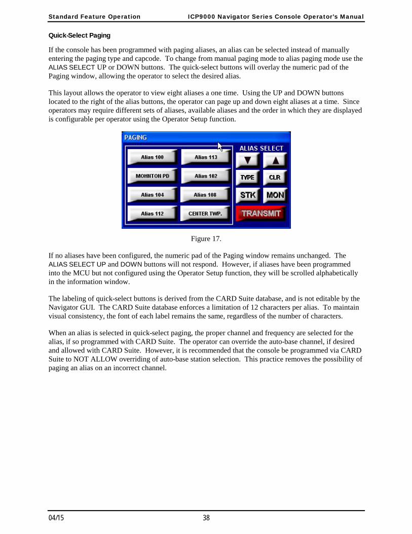
Standard Feature Operation ICP9000 Navigator Series Console Operator’s Manual
04/15 38
Quick-Select Paging
If the console has been programmed with paging aliases, an alias can be selected instead of manually entering the paging type and capcode. To change from manual paging mode to alias paging mode use the ALIAS SELECT UP or DOWN buttons. The quick-select buttons will overlay the numeric pad of the Paging window, allowing the operator to select the desired alias.
This layout allows the operator to view eight aliases a one time. Using the UP and DOWN buttons located to the right of the alias buttons, the operator can page up and down eight aliases at a time. Since operators may require different sets of aliases, available aliases and the order in which they are displayed is configurable per operator using the Operator Setup function.
Figure 17.
If no aliases have been configured, the numeric pad of the Paging window remains unchanged. The ALIAS SELECT UP and DOWN buttons will not respond. However, if aliases have been programmed into the MCU but not configured using the Operator Setup function, they will be scrolled alphabetically in the information window.
The labeling of quick-select buttons is derived from the CARD Suite database, and is not editable by the Navigator GUI. The CARD Suite database enforces a limitation of 12 characters per alias. To maintain visual consistency, the font of each label remains the same, regardless of the number of characters.
When an alias is selected in quick-select paging, the proper channel and frequency are selected for the alias, if so programmed with CARD Suite. The operator can override the auto-base channel, if desired and allowed with CARD Suite. However, it is recommended that the console be programmed via CARD Suite to NOT ALLOW overriding of auto-base station selection. This practice removes the possibility of paging an alias on an incorrect channel.
ICP9000 Navigator Series Console Operator’s Manual Standard Feature Operation
39 04/15
Initiating the Page
When the desired capcode is entered or alias selected the operator should activate monitor on the channel to ensure that the radio channel is not in use. When the channel is free, the operator should press the page TRANSMIT button or the main TRANSMIT button. The paging tones can be heard through the select speaker as they are transmitted.
When the paging tones are complete, “TALK NOW” flashes at the upper right of the information window if talk time has been programmed for the particular type of paging or alias. While “TALK NOW” is flashing, the microphone is active and voice audio is transmitted over the channel(s) to the paged units. To extend the talk time, press and hold the main TRANSMIT, page TRANSMIT or channel TRANSMIT button.
Additionally, it is possible to initiate an alert tone during the talk time. To activate an alert while “TALK NOW” is flashing, simply press the desired alert tone button. Upon releasing the alert tone button, the console will again flash “TALK NOW” at the upper right of the information window for a minimum of two seconds. During this time, the microphone is active and voice audio is transmitted over the channel(s). To extend the talk time, press and hold the main TRANSMIT, page TRANSMIT or channel TRANSMIT button.
When the talk time is over, the operator releases the appropriate transmit button or if no talk time has been programmed, the console exits paging mode, returns to normal operation, or hot standby paging, and selects the previously selected channel. As discussed earlier, the operator should exercise caution when following a page with a voice transmission to ensure that the correct channel is selected.
Sequential Channel Specific Group Paging
A special type of alias preprogrammed with a sequence of other aliases is called a group page. A group page is configured using CARD Suite and contains of list of alias pages that are sequentially transmitted on the auto-base station channel, as programmed in each alias. This allows for activation of multiple sirens or paging of several emergency services at once. As a group page progresses, each alias in the group is referenced, and the channel and frequency on which it has been preprogrammed to page are selected.
The alias is displayed on the paging line and the paging tones are heard through the select speaker as the page is transmitted. Upon completion of all pages, “TALK NOW” flashes at the upper right of the display if a talk time has been programmed for the group. During this time, the microphone is active and voice audio is transmitted over the channel(s). To extend the talk time, press and hold the main TRANSMIT, page TRANSMIT or channel TRANSMIT button on any transmitting channel.
When the talk time is over, the operator releases the appropriate transmit button or if no talk time has been programmed, the console exits paging mode, returns to normal operation, or hot standby paging, and selects the previously selected channel. As discussed earlier, the operator should exercise caution when following a page with a voice transmission to ensure that the correct channel is selected.
Standard Feature Operation ICP9000 Navigator Series Console Operator’s Manual
04/15 40
Stack Paging
The Stack paging feature provides the operator the capability to create a sequential group page as needed. A stack page can consist of manual pages, alias pages and even group pages. Up to ten individual or group pages can be stacked. A group page counts as one entry in the stack.
To create a stack page, as with manual mode or alias mode paging, select the desired page and paging channel, if applicable. To stack the displayed page, press the STK button. The page is stacked and the paging line now shows *STACK PAGE: 2* indicating that the second page can now be entered and stacked. To continue creating the stack page, repeat this process until the final page is displayed. DO NOT stack the last page by pressing the STK button.
If a page is stacked in error, press the CLR key until the page in question in displayed. Correct the entry as described in manual or alias mode paging and proceed with the creation of the stack page.
Once the final page is entered, but not stacked, press the TRANSMIT button or main TRANSMIT button to begin the transmission of the stacked pages. As the stack page is generated, the proper paging channel is selected and the paging line displays the page being generated and *PAGING X OF Y* where X is the number of the current page being transmitted and Y is the number of pages in the stack. If a group is stacked in the page, as described previously, the individual aliases are displayed as they are transmitted. A group page, however, counts as one entry in the stack.
If any page in the stack has a talk time programmed, the longest talk time is used for the talk time. Upon completion of all pages, “TALK NOW” flashes at the upper right of the display if a talk time has been programmed for any of the transmitted aliases. During this time, the microphone is active and voice audio is transmitted over the channel(s). To extend the talk time, press and hold the main TRANSMIT, page TRANSMIT or channel TRANSMIT button on any transmitting channel.
When the talk time is over, the operator releases the appropriate transmit button or if no talk time has been programmed, the console exits paging mode, returns to normal operation, or hot standby paging, and selects the previously selected channel. As discussed earlier, the operator should exercise caution when following a page with a voice transmission to ensure that the correct channel is selected.
The pages of the stack are kept until the console is reset. Therefore, to repeat a stack page, simply reenter paging and begin stacking the pages. As they are stacked, each page that was stacked previously is displayed as long as no other pages have been transmitted. All that is required is to press the STK button to confirm the stacking of each page. No reselection or reentry of pages is required.
Hot Standby Paging
Unless configured not to do so, upon exiting page mode, the console automatically closes the paging window. To page again, the operator must again press the toolbar PAGE button to reopen the paging window to reenter paging mode.
To allow for quicker entry into paging mode, the Navigator can be configured to remain in hot standby paging mode. When this mode of operation is selected, upon exiting page mode, the paging window remains open, but dimmed. While in hot standby paging mode, from normal operating mode, click inside of the paging window to reenter paging. To enable hot standby paging, click on Setup on the menu bar, and on the Operator Setup form, check Paging window in Operator options.
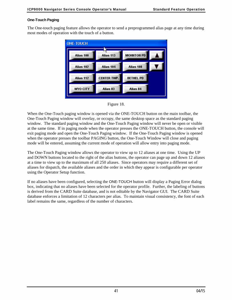
ICP9000 Navigator Series Console Operator’s Manual Standard Feature Operation
41 04/15
One-Touch Paging
The One-touch paging feature allows the operator to send a preprogrammed alias page at any time during most modes of operation with the touch of a button.
Figure 18.
When the One-Touch paging window is opened via the ONE-TOUCH button on the main toolbar, the One-Touch Paging window will overlay, or occupy, the same desktop space as the standard paging window. The standard paging window and the One-Touch Paging window will never be open or visible at the same time. If in paging mode when the operator presses the ONE-TOUCH button, the console will exit paging mode and open the One-Touch Paging window. If the One-Touch Paging window is opened when the operator presses the toolbar PAGING button, the One-Touch Window will close and paging mode will be entered, assuming the current mode of operation will allow entry into paging mode.
The One-Touch Paging window allows the operator to view up to 12 aliases at one time. Using the UP and DOWN buttons located to the right of the alias buttons, the operator can page up and down 12 aliases at a time to view up to the maximum of all 250 aliases. Since operators may require a different set of aliases for dispatch, the available aliases and the order in which they appear is configurable per operator using the Operator Setup function.
If no aliases have been configured, selecting the ONE-TOUCH button will display a Paging Error dialog box, indicating that no aliases have been selected for the operator profile. Further, the labeling of buttons is derived from the CARD Suite database, and is not editable by the Navigator GUI. The CARD Suite database enforces a limitation of 12 characters per alias. To maintain visual consistency, the font of each label remains the same, regardless of the number of characters.
Standard Feature Operation ICP9000 Navigator Series Console Operator’s Manual
04/15 42
Alert Page
It is possible to send out an individual, group or stack page followed by an alert tone. To generate an alert page, select the page or pages to be transmitted. Press and hold the desired alert tone button instead of the TRANSMIT button. The console generates the page(s) and approximately one second after the last page, begins the generation of the alert tone. The alert can be generated for up to eight seconds as long as the alert tone button is held.
Upon releasing the alert tone button or at the end of the alert tone, the console will flash “TALK NOW” at the upper right of the information window for a minimum of two seconds. During this time, the microphone is active and voice audio is transmitted over the channel(s). To extend the talk time, press and hold the main TRANSMIT, page TRANSMIT or channel TRANSMIT button.
When the operator releases the appropriate transmit button or the two seconds time out, the console exits paging mode, returns to normal operation, or hot standby paging, and selects the previously selected channel. As discussed earlier, the operator should exercise caution when following a page with a voice transmission to ensure that the correct channel is selected.
Immediate DTMF Paging
Immediate DTMF Paging is slightly different from the other paging formats in that there are no limits on the number of digits that can be transmitted, and there are no preset aliases available. To select Immediate DTMF paging, ensure the console is in manual paging mode and that DTMF paging is enabled on the desired channel using CARD Suite. Press the TYPE button until IMMED. DTMF is displayed on the paging line.
Pressing a digit causes the channel to begin transmission and to transmit the DTMF digit over the channel. The digit can be heard through the select speaker as it is generated. If the console channel is not currently transmitting, there is a slight delay upon pressing the first digit to allow the base station to begin transmission. It is necessary to press and hold the first digit until it is heard from the select speaker. Upon releasing the button, the channel continues to transmit for approximately two seconds to allow additional digits to be entered. The operator can enter more digits or can begin a voice transmission by pressing and holding the TRANSMIT button. To exit immediate DTMF paging, press the PAGE button on the Navigator tool bar or select another type of paging using the TYPE button.
Manual Paging Enable/Disable
Use the CARD Suite software application to enable or disable each type of paging (such as DTMF/Immediate DTMF, 2-Tone, 5/6 Tone, and 2805/1500) on each channel. If disabled, the paging type does not appear on the display during manual paging as described in the “Manual Paging” section of this manual. Consult with the system supervisor regarding disabling manual paging.
ICP9000 Navigator Series Console Operator’s Manual Standard Feature Operation
43 04/15
Auto-Base Station Override
Use the CARD Suite software application to enable or disable the auto-base station override. If this option is enabled, while in quick-select paging, the console operator can override the preprogrammed transmit channel for an alias using the channel SELECT buttons. Unless the operator is very familiar with the way the console uses paging channels and selected channels, allowing override of the auto-base station select is not recommended.
If this option is disabled while in quick-select paging, the console automatically selects the paging channel and the channel SELECT buttons are inoperative. This ensures that the proper channel is ALWAYS selected when using an alias to page.
Exiting Paging Mode
Press the PAGE button again to exit paging mode.

Standard Feature Operation ICP9000 Navigator Series Console Operator’s Manual
04/15 44
DTMF Decode DTMF Decode allows the console to accept Automatic Number Identification (ANI) information from radios equipped with DTMF/ANI capabilities or DTMF sequences from other devices. DTMF Decode provides a capability similar to PTT-ID. It eliminates the need to use additional airtime to identify the caller by a voice message and provides a means for manually logging system traffic. DTMF Decode also discourages inappropriate use of a radio since management has positive identification of who is on the air at any given time.
If a DTMF sequence is decoded and it meets the DTMF decode parameters as set by the CARD Suite software, the decoded sequence is entered into a first-in-first-out (FIFO) queue that can contain 15 separate entries. The decoded sequence is displayed in the information window and if the sequence matches a preprogrammed DTMF-decode alias, the alias is displayed. Individual entries can be deleted from the queue by first scrolling the queue using the SCROLL Up/Down arrows so that the entry is at the top of the queue and then pressing the DEL button.
In the information window shown below, there are ten entries currently in the queue indicated by the 10 after the 4, 5, 6 and 7. The 4th entry is an entry that did not have a DTMF-decode alias programmed in the console. The 5th, 6th, and 7th entries each had a DTMF-decode alias programmed in the console. As shown below, the operator has scrolled down through the queue. There are three more entries above the information window shown below and three more entries below. If the operator were to press the DEL button, the 4th entry, ID 189300, would be permanently deleted from the queue. Entries 5 through 10 would then move up one position to become entries 4 through 9.
CHANNEL 1/1 PL-A CODED RECEIVE 4/10 ID 189300 DTMF 189300 11:04A 5/10 Sgt. Barnes DTMF 189299 11:02A 6/10 Sheriff Kochel DTMF 190001 10:56A 7/10 CallBox 101 DTMF 700101 10:45A
Figure 19. Information Window showing DTMF Decode Example
In addition to providing the DTMF decode information in the information window, the DTMF decode information is also logged to the printer port of Navigator MCU. If desired, this information can be printed on a serial printer for a printed record, or can be captured by the Navigator PC through the use of a second serial port and a program, such as HyperTerminal, which is a standard Windows® program. If captured by HyperTerminal, the data can be saved to a network location or printed as desired. The operator can also view the logged data in HyperTerminal by bringing it to the top of the PC desktop.
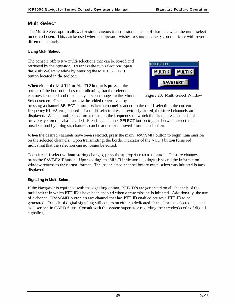
ICP9000 Navigator Series Console Operator’s Manual Standard Feature Operation
45 04/15
Multi-Select The Multi-Select option allows for simultaneous transmission on a set of channels when the multi-select mode is chosen. This can be used when the operator wishes to simultaneously communicate with several different channels.
Using Multi-Select
The console offers two multi-selections that can be stored and retrieved by the operator. To access the two selections, open the Multi-Select window by pressing the MULTI SELECT button located in the toolbar.
When either the MULTI 1 or MULTI 2 button is pressed, the border of the button flashes red indicating that the selection can now be edited and the display screen changes to the Multi-Select screen. Channels can now be added or removed by pressing a channel SELECT button. When a channel is added to the multi-selection, the current frequency F1, F2, etc., is used. If a multi-selection was previously stored, the stored channels are displayed. When a multi-selection is recalled, the frequency on which the channel was added and previously stored is also recalled. Pressing a channel SELECT button toggles between select and unselect, and by doing so, channels can be added or removed from the selection.
When the desired channels have been selected, press the main TRANSMIT button to begin transmission on the selected channels. Upon transmitting, the border indicator of the MULTI button turns red indicating that the selection can no longer be edited.
To exit multi-select without storing changes, press the appropriate MULTI button. To store changes, press the SAVE/EXIT button. Upon exiting, the MULTI indicator is extinguished and the information window returns to the normal format. The last selected channel before multi-select was initiated is now displayed.
Signaling in Multi-Select
If the Navigator is equipped with the signaling option, PTT-ID’s are generated on all channels of the multi-select in which PTT-ID’s have been enabled when a transmission is initiated. Additionally, the use of a channel TRANSMIT button on any channel that has PTT-ID enabled causes a PTT-ID to be generated. Decode of digital signaling still occurs on either a dedicated channel or the selected channel as described in CARD Suite. Consult with the system supervisor regarding the encode/decode of digital signaling.
Figure 20. Multi-Select Window
Standard Feature Operation ICP9000 Navigator Series Console Operator’s Manual
04/15 46
Multi-Select Alert
After the multi-select has been selected, it is possible to generate an attention-getting alert tone to all the selected channels by pressing the desired alert tone button. When the operator presses the alert tone button, the alert tone is generated as described previously. When the alert tone is complete, the operator can use the TRANSMIT button to transmit to all selected channels.
Operations of Channel Transmit during Multi-Select Mode
One restriction applies to the use of the channel TRANSMIT button, as well as many of the programmable button functions, while in multi-select mode. While selecting the multi-select, indicated by the flashing multi-select indicator, the use of the channel TRANSMIT button is prohibited. This is necessary since the selection of a multi-select uses previously configured channel settings that may include different frequency and secure mode settings. If the channel TRANSMIT button were used in multi-select edit mode, the operator may intend to transmit on one channel/frequency while they may, in fact, transmit on a different frequency than desired. After the first multi-select transmit, however, the channel TRANSMIT buttons can be used.

ICP9000 Navigator Series Console Operator’s Manual Standard Feature Operation
47 04/15
Positive Mode Control/Secure Operation The Navigator supports positive mode control for controlling a secure-equipped base station. The operator must control the secure mode of the console by selecting a coded or clear transmission type. The actual encryption and decryption of audio is a function of the base station and not the console. The console simply controls the feature.
Using Positive Mode Control
To open the secure window to access the CODED and CLEAR buttons, press the toolbar SECURE button.
When the CODED button is pressed, the border of the CODED button lights red to indicate transmit audio from the selected channel should be encrypted by the transmitter. The status line of the information window also displays CODED to indicate that the selected channel is now in coded mode. The selected channel remains in this mode until the CLEAR button is pressed.
When the CLEAR button is pressed, the border of the CODED is extinguished and the border of the CLEAR button lights red to indicate transmit audio from the selected channel should no longer be encrypted by the transmitter. The status line of the information window also displays CLEAR to indicate that the selected channel is now in clear mode.
Coded Reception Indicator
The CODED and CLEAR on the status line of the information window always indicate the secure state of the selected channel and whether or not transmissions are to be encrypted by the transmitter. The CODED button indicator, however, serves two purposes. If a channel is secure capable, either the CODED or CLEAR indicator is lit.
However, if the console is properly configured and installed, the CODED indicator provides the secure status of the last received audio on a secure channel. If the CODED indicator is flashing when a channel is selected, it indicates that the last received audio on that channel was encrypted and the operator should set the transmit secure status to the proper setting. This received transmission status is latched whether the channel is selected or not.
To ensure that the operator selects the proper secure state for transmissions in response to a potentially encrypted reception, the operator should always select a secure channel prior to transmitting to determine the secure status of the last reception. Using the channel TRANSMIT button does not provide the necessary information to the operator prior to responding.
Figure 21. Secure Window
Standard Feature Operation ICP9000 Navigator Series Console Operator’s Manual
04/15 48
Secure Operation in Multi-Select
Secure operation is available while in multi-select mode. If all channels in the multi-selection are secure capable, the status line and CODED/CLEAR indicators indicate either coded or clear mode. The operator can select coded or clear transmission while either the coded or clear mode is indicated.
If, however, any one channel in the selection is not secure capable, neither coded nor clear are indicated. When this is the case, the operator cannot select coded or clear transmission and all secure capable channels are switched to clear transmission mode. The secure channels in the selection, however, retain their prior clear/coded settings when multi-select is exited.
49 04/15
Options
DC Remote Control CP0010/XCP0010 DC Control uses a different method to control the base station, which does not provide the functionality of a tone remote system. Therefore, certain features behave differently or cannot be used on a channel using dc remote control. Consult with the system supervisor to understand what features are available on each channel.
Buttons Not Applicable to DC Control
If the selected channel uses dc remote control, some features are not available. These features include secure operation and MULTI PL. If the operator attempts to activate any of these features, an error beep is generated.
Frequency Buttons with DC Control
The frequency buttons, F1, F2, F3 and F4 in the Frequency window, are used to change the PTT current for the selected channel. DC channels do not support more than four different transmission currents. Therefore, multi-frequency is not compatible with dc operation.
Monitor Button with DC Control
The MONITOR button behaves differently on a dc remote control channel than that of a tone remote control channel. On a dc remote control channel, the monitor function is not latched; and therefore, the operator must press and hold the MONITOR button. While the MONITOR button is depressed, the border of the MONITOR button lights yellow and MONITOR is displayed on the right side of the information window status line. When the button is released, the border of the MONITOR button returns to its original color and RECEIVE is displayed on the right side of the information window status line. The channel and base station are no longer in monitor mode after the release of the MONITOR button. This functionality is the same for any channel monitor buttons on a dc channel.
Options ICP9000 Navigator Series Console Operator’s Manual
04/15 50
E&M Signaling CP0040/XCP0040 The E&M Signaling option is used to control E&M signaling stations. This type of control offers fewer features than either tone remote or dc remote control. Consult with the system supervisor to understand what features are available on each channel.
Buttons Not Applicable to E&M Control
If the selected channel is operating with E&M control, several features are not available. These features include the programmable buttons, frequency buttons, monitor, secure operation and MULTI-PL. If the operator attempts to activate any of these features, an error beep is generated.
E&M with Tone Remote Control
The E&M Signaling option supports E&M with tone remote control, which allows the features of tone remote control to be transmitted using one radio to a receiving radio that controls the actual base station. In this type of control, the operator may notice that there is a longer time before TRANSMIT is displayed on the status line when the operator is allowed to make a transmission. The operator should be aware of this added delay in transmitting to prevent the possibility clipping the first syllable of a word when initiating a voice transmission.
ICP9000 Navigator Series Console Operator’s Manual Options
51 04/15
Supervisory Control CP0050/XCP0050 The Supervisory Control option gives a designated operator the ability to physically disconnect the transmit audio lines from one or more parallel-connected console channels with the touch of a single button. This is used to lock out any parallel consoles from transmitting on a specific channel or group of channels.
Activating Supervisor Control
To activate or deactivate supervisor control for a selected channel, press the toolbar SUPERVISOR button for less than one second. When the toolbar SUPERVISOR button is pressed, supervisor control is activated for the selected channel. The SUPERVISOR button’s border turns red to provide indication that the selected channel has supervisor control activated.
To activate or deactivate supervisor control for any channel with a channel supervisor button, simply press and release the channel supervisor button. If activated, the channel supervisor indicator will light. If the channel is the selected channel, the toolbar SUPERVISOR indicator will light as well.
While supervisor control is activated for the selected channel, the right side of the status line in the information window indicates SUPERVISOR. To deactivate supervisor control for the selected channel, press the toolbar SUPERVISOR button a second time for less than one second or press the channel supervisor button on the select channel if available.
The SUPERVISOR button indicator located in the Navigator tool bar indicates the state of the console’s supervisor option while in normal operation. If the SUPERVISOR button’s border is red, it indicates that parallel consoles are not allowed to transmit on the selected channel. Other channels can also have supervisor control activated as well. If the button border is flashing, it indicates that the selected channel does not have supervisor control activated, but another channel does have supervisor activated.
To deactivate supervisor control on all channels without having to select each channel in turn, press and hold the toolbar SUPERVISOR button for more than one second. This deactivates supervisor control on all channels removing the need to manually select each channel and deactivate supervisor control for each.
Supervisory Control Using Multi-Select
Upon entering the multi-select mode, any channels that currently have supervisor control activated are highlighted in the information window.
If the SUPERVISOR button is pressed while in multi-select mode and multi-select supervisor is deactivated, all channels in the selection that have been programmed using CARD Suite software to have supervisor control enabled are highlighted on the information screen. When supervisor control is deactivated while in multi-select mode, all channels in the selection that did not have supervisor control activated prior to entering multi-select have supervisor control deactivated. Note that global deactivation is not available while in multi-select mode.
If the operator activates/deactivates supervisor on a channel using its channel supervisor button while in multi-select, the channel supervisor button indicator will indicate the supervisor state of the channel outside of multi-select regardless of the multi-select supervisor state.
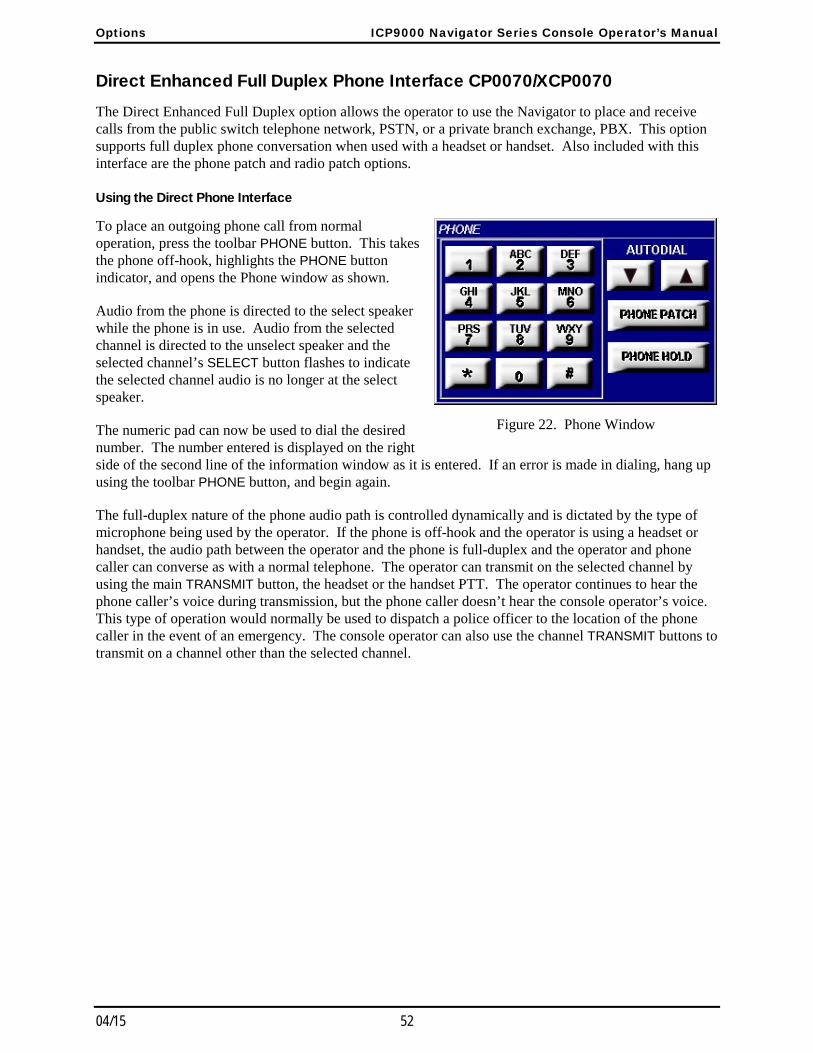
Options ICP9000 Navigator Series Console Operator’s Manual
04/15 52
Direct Enhanced Full Duplex Phone Interface CP0070/XCP0070 The Direct Enhanced Full Duplex option allows the operator to use the Navigator to place and receive calls from the public switch telephone network, PSTN, or a private branch exchange, PBX. This option supports full duplex phone conversation when used with a headset or handset. Also included with this interface are the phone patch and radio patch options.
Using the Direct Phone Interface
To place an outgoing phone call from normal operation, press the toolbar PHONE button. This takes the phone off-hook, highlights the PHONE button indicator, and opens the Phone window as shown.
Audio from the phone is directed to the select speaker while the phone is in use. Audio from the selected channel is directed to the unselect speaker and the selected channel’s SELECT button flashes to indicate the selected channel audio is no longer at the select speaker.
The numeric pad can now be used to dial the desired number. The number entered is displayed on the right side of the second line of the information window as it is entered. If an error is made in dialing, hang up using the toolbar PHONE button, and begin again.
The full-duplex nature of the phone audio path is controlled dynamically and is dictated by the type of microphone being used by the operator. If the phone is off-hook and the operator is using a headset or handset, the audio path between the operator and the phone is full-duplex and the operator and phone caller can converse as with a normal telephone. The operator can transmit on the selected channel by using the main TRANSMIT button, the headset or the handset PTT. The operator continues to hear the phone caller’s voice during transmission, but the phone caller doesn’t hear the console operator’s voice. This type of operation would normally be used to dispatch a police officer to the location of the phone caller in the event of an emergency. The console operator can also use the channel TRANSMIT buttons to transmit on a channel other than the selected channel.
Figure 22. Phone Window
ICP9000 Navigator Series Console Operator’s Manual Options
53 04/15
If the operator is using the gooseneck or internal microphone, or has activated the select speaker off-hook override or phone patch, the audio path between the operator and the phone is forced to half-duplex. This removes the possibility of feedback between the microphone and speaker. The operator can use the TRANSMIT button, the headset or the handset PTT to talk to the phone caller when the half-duplex mode is active. The operator must use the channel TRANSMIT button to transmit on any channel. While transmitting on a console channel, the operator’s voice audio is not heard by the phone caller, but the operator continues to hear the phone caller’s voice. To mute the phone caller’s voice, press the PHONE
HOLD button. When on hold, the PHONE HOLD indicator is lit.
While the phone is in use, certain modes of operation may be restricted. Placing the caller on hold using the PHONE HOLD button will allow all console functions to be accessible and the console will operate as if the phone were not in use. While the caller is on hold, the border indicator of the PHONE HOLD button is lit. To take the caller off hold, press the PHONE HOLD button again. To disconnect the caller, press the toolbar PHONE button at any time.
Auto-Dial and Last Number Redial
Auto-dial numbers can be programmed using the CARD Suite Software application. These numbers can be used when dialing the phone by first taking the phone off-hook and pressing the SCROLL Up/Down buttons to select the desired auto-dial alias. When the desired alias is displayed, press the TRANSMIT button to automatically dial the associated number.
When the phone is taken off-hook later, the last number dialed is displayed. The displayed number can be dialed again by pressing the TRANSMIT button. The number can be cleared by initiating a new number with the numeric keypad or by pressing the CLEAR button.
Options ICP9000 Navigator Series Console Operator’s Manual
04/15 54
Answering Incoming Calls
When an incoming call is detected, an audible ring is heard through the select speaker and the PHONE indicator flashes. To answer an incoming call, press the toolbar PHONE button. The PHONE indicator lights and the Phone window opens. At this point, the call proceeds and behaves as described in the Using the “Direct Enhanced Full Duplex Phone Interface” section.
Phone Patch
Phone Patch allows the phone caller to be connected to a channel for voice communication between the two. The operator is able to monitor both phone and radio audio. A phone patch can be either an inbound phone caller requesting a radio channel, or a radio channel requesting a phone line.
To activate a phone patch, press the PHONE PATCH button. The phone caller is placed on hold and the PHONE PATCH indicator begins to flash. The flashing PHONE PATCH indicator signals the operator to select the radio channel for the phone patch. The TRANSMIT button now allows voice transmission on the selected phone patch channel. Once the operator has contacted the field unit to relay that a phone patch is being established, the operator must take the phone off hold by pressing the PHONE HOLD button.
At this point, the PHONE PATCH indicator lights and the phone patch is established. Since the patch is based on voice detection on the radio channel and phone, the phone audio is forced to half-duplex mode. The operator should now announce to the phone caller and the field unit that the patch is established using the TRANSMIT button. The phone caller and field unit can have a half-duplex, one-at-a-time, conversation. At anytime during the phone patch, the console operator can communicate with both the phone caller and the field unit by pressing and holding the TRANSMIT button. The console operator can also communicate with the field unit without the knowledge of the phone caller by using the channel TRANSMIT button on the phone patch channel.
To pause the phone patch without terminating it, the operator can put the phone caller on hold. Placing the phone caller on hold during a phone patch maintains the patch, but allows the console operator to conduct other business or have a conversation with the field unit without interference from the phone caller. Removing the phone caller from hold continues the patch as described earlier.
The phone patch can be terminated by either pressing the toolbar PHONE button or by pressing the PHONE PATCH button.
ICP9000 Navigator Series Console Operator’s Manual Options
55 04/15
External Enhanced Full Duplex Phone Interface CP0060/XCP0060 The External Enhanced Full Duplex Phone Interface option allows the operator to use the ICP9000 Navigator to place and receive calls with an external phone. This option supports full duplex phone conversation when used with a headset or handset. Also included with this interface are the phone patch and radio patch options.
Using the External Phone Interface
If the external phone activates the off-hook request while the console is in the normal operation, the console immediately switches to phone mode, activating the toolbar PHONE indicator and opening the phone window. If the console is not in normal operation mode (radio patch, multi-select, page, etc.), or any button is pressed on the console when the off-hook request is activated, the phone cannot be used and the toolbar PHONE indicator flashes. Once the console returns to normal mode or the button is released, the console immediately switches to phone mode.
The full-duplex nature of the phone audio path is controlled dynamically and is dictated by the type of microphone being used by the operator. If the phone is off-hook and the operator is using a headset or handset, the audio path between the operator and the phone is full-duplex and the operator and phone caller can converse as with a normal telephone. The operator can transmit on the selected channel by using the main TRANSMIT button, the headset or handset PTT. The operator continues to hear the phone caller’s voice during transmission, but the phone caller does not hear the console operator’s voice. This type of operation would normally be used to dispatch a police officer to the location of the phone caller in the event of an emergency. The console operator can also use the channel TX buttons to transmit on a channel other than the selected channel.
If the operator is using the gooseneck or internal microphone and has activated the select speaker off-hook override or phone patch, the audio path between the operator and the phone is forced to half-duplex. This removes the possibility of feedback between the microphone and speaker. The operator must use the TRANSMIT button, the headset or handset PTT to talk to the phone when half-duplex mode is active. The operator must use the channel TRANSMIT button to transmit on any channel. While transmitting on a console channel, the console operator’s voice audio is not heard by the phone caller, but the operator continues to hear the phone caller’s voice. To mute the phone caller’s voice, the call must be placed on hold with the external phone.
While the phone is in use, certain modes of operation may be restricted. Placing the caller on hold using the PHONE HOLD button will allow all console functions to be accessible and the console will operate as if the phone were not in use.
Phone Patch with External Phone Interface
Phone patch operation is available with the external phone interface and operates as described in the “Direct Enhanced Phone Interface” section of this manual.
Options ICP9000 Navigator Series Console Operator’s Manual
04/15 56
Radio Patch Radio patch is part of the Direct Enhanced Full Duplex Phone Interface and the External Enhanced Full Duplex Phone Interface options. It allows any number of console channels to be connected to each other allowing one group to talk to other groups through the console. The console uses voice detection to determine which channel transmits to the others at any given time. Further, there is a delay after voice detection ceases on a channel before the transmission is ceased on the other channels to allow for pauses in normal speech. When a radio patch is active, other modes of operation such as paging, multi-select and use of the phone are prohibited.
Using Radio Patch
When RADIO PATCH button is pressed, the border of the button flashes red indicating that the selection can now be edited, and the display screen changes to the Radio Patch screen. By design, no channels are pre-selected upon entering radio patch. Channels (up to 12, if applicable) may now be added or removed by pressing a channel SELECT button. When a channel is added to the patch selection, the current frequency F1, F2, etc., is used. If a channel utilizes a channel frequency change programmable button, this feature may be used during the selection process to alter the channel frequency for the radio patch. Upon exiting radio patch, all channels will revert to the frequency on which they were set prior to entering radio patch.
When the desired channels have been selected, press the main TRANSMIT button to establish the patch and begin the transmission. The operator may then announce to the channels that the patch has been established. Upon transmitting, the border indicator of the RADIO PATCH button turns red indicating that the selection can no longer be edited.
By using the main TRANSMIT button, the console operator is able to simulcast to all parties at any time during the radio patch. This is similar to the multi-select feature. To talk to any channel individually, including the radio patch channels, the channel TRANSMIT button must be used.
To exit radio patch, press the RADIO PATCH button. Upon exiting, all channels will revert to their prior frequency, the RADIO PATCH indicator is extinguished and the information window returns to the normal format. The last selected channel before radio patch was initiated is now displayed.
Signaling in Radio Patch
If any channel of the patch has PTT-ID enabled and the Navigator is equipped with the signaling option, PTT-ID’s are generated on those patch channels when the TRANSMIT button is pressed. Additionally, the use of a channel TRANSMIT button on any channel that has PTT-ID enabled causes a PTT-ID to be generated. Decode of digital signaling still occurs on either a dedicated channel or the selected channel as described in CARD Suite. Consult with the system supervisor regarding encode/decode of digital signaling.
Radio Patch Alert
After the radio patch channels have been selected, it is possible to generate an attention getting alert tone to all patch channels by pressing the ALT button. When the operator presses the ALT button, an alert tone is generated as described previously. When the alert tone is complete, the operator can use the TRANSMIT button to simulcast to all patch channels.
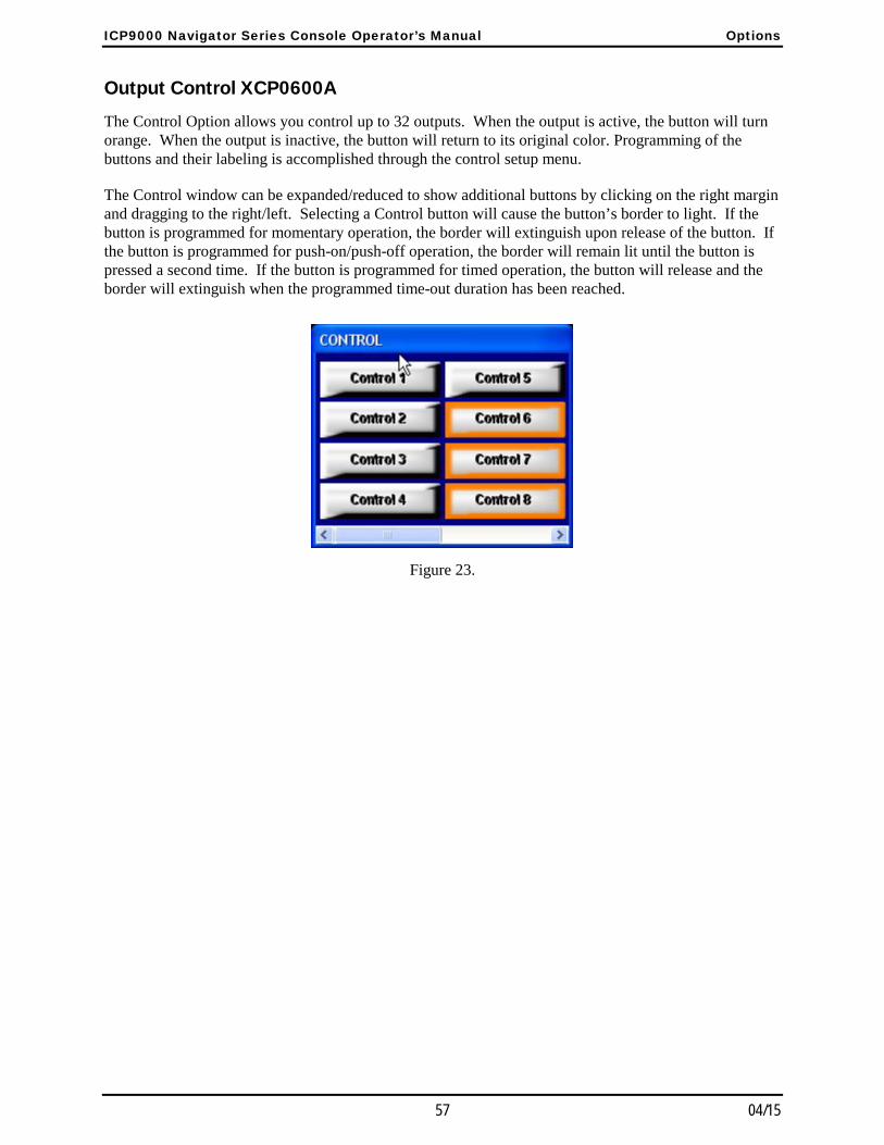
ICP9000 Navigator Series Console Operator’s Manual Options
57 04/15
Output Control XCP0600A The Control Option allows you control up to 32 outputs. When the output is active, the button will turn orange. When the output is inactive, the button will return to its original color. Programming of the buttons and their labeling is accomplished through the control setup menu.
The Control window can be expanded/reduced to show additional buttons by clicking on the right margin and dragging to the right/left. Selecting a Control button will cause the button’s border to light. If the button is programmed for momentary operation, the border will extinguish upon release of the button. If the button is programmed for push-on/push-off operation, the border will remain lit until the button is pressed a second time. If the button is programmed for timed operation, the button will release and the border will extinguish when the programmed time-out duration has been reached.
Figure 23.

Options ICP9000 Navigator Series Console Operator’s Manual
04/15 58
MDC1200 STAT-ALERT Signaling CP0650/TDN9413A The ICP9000 Navigator’s MDC1200 STAT-ALERT Signaling option supports encode and decode of MDC1200 data. To access the signaling screen, press the SIGNALING button located in the Navigator toolbar. The console enters signaling mode and opens the Signaling window as shown below.
Figure 24.
RapidCall buttons on the ICP9000 Navigator are: CALL ALERT, SELECT CALL, RADIO CK, SHORT CALL
ALERT, RADIO DISABLE, RADIO ENABLE and EMR RESET.
Call Alert and Short Call Alert are used to alert mobile operators away from their vehicles to call the console operator. When a mobile radio receives a Call Alert, it will generate alert tones until the mobile operator manually shuts them off or transmits.
Radio Check allows the console operator to determine if a mobile radio is operational or within range. The mobile radio will return an acknowledgement that it received the Radio Check.
Radio Disable prevents radio use should a mobile radio be lost or stolen. An appropriately equipped mobile radio that receives a Radio Disable message (specifically directed to that radio) will become inoperative. Radio Enable re-enables a disabled mobile radio.
Select Call allows an individual ID or group to be called without disturbing other units. Select Call is essentially a RapidCall paging feature. The receiving mobile will generate alert beeps prior to unmuting its speaker.
All call types available in the Navigator, with the exception of Select Call, require an acknowledgement from the destination radio unless the destination ID is a group ID or contains a wildcard digit. Most field units can be programmed with a unique ID as well as a group ID to allow for addressing a number of units as a group. Unique ID’s range from “0001” to “DEEE”. Note that “0000” is not a valid ID. A group ID is any ID with the number ‘E’ or ‘*’ as the fourth digit and can range from “E001” to “EEEE”. For example, the ID “E001” or “*001” is a group ID while “0E01” or “0*01” is not. A wildcard ID is any ID containing an ‘F’ or ‘#’ in any location. Some examples of a wildcard ID are “#001”, “0F01” and “####”. A wildcard ID matches any number. Therefore, a wildcard ID of “000#” matches any ID from “0001” to “000E”. Note that the use of wildcards in the fourth position such as “#001” will not match a group ID of “E001”.
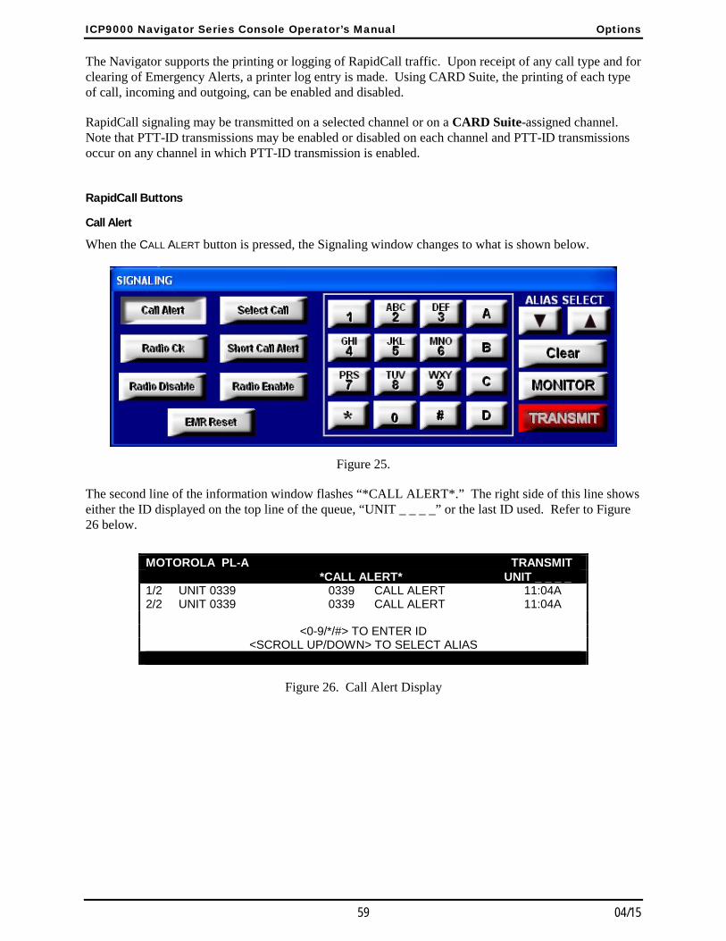
ICP9000 Navigator Series Console Operator’s Manual Options
59 04/15
The Navigator supports the printing or logging of RapidCall traffic. Upon receipt of any call type and for clearing of Emergency Alerts, a printer log entry is made. Using CARD Suite, the printing of each type of call, incoming and outgoing, can be enabled and disabled.
RapidCall signaling may be transmitted on a selected channel or on a CARD Suite-assigned channel. Note that PTT-ID transmissions may be enabled or disabled on each channel and PTT-ID transmissions occur on any channel in which PTT-ID transmission is enabled.
RapidCall Buttons
Call Alert
When the CALL ALERT button is pressed, the Signaling window changes to what is shown below.
Figure 25.
The second line of the information window flashes “*CALL ALERT*.” The right side of this line shows either the ID displayed on the top line of the queue, “UNIT _ _ _ _” or the last ID used. Refer to Figure 26 below.
MOTOROLA PL-A TRANSMIT *CALL ALERT* UNIT _ _ _ _ 1/2 UNIT 0339 0339 CALL ALERT 11:04A 2/2 UNIT 0339 0339 CALL ALERT 11:04A
<0-9/*/#> TO ENTER ID
<SCROLL UP/DOWN> TO SELECT ALIAS
Figure 26. Call Alert Display
Options ICP9000 Navigator Series Console Operator’s Manual
04/15 60
Selecting a unit ID for transmission is accomplished in one of three ways.
Instant Send – If a valid unit ID or alias name is shown on the second line of the information window, the TRANSMIT button may be pressed to immediately send the Call Alert to this ID.
Manual Entry – A specific mobile unit ID can be entered using the numeric keypad. The ID entered will be displayed on the second line of the information window. In case a mistake is made during digit entry, the CLEAR button can be pressed and another attempt made. When the correct ID is entered, the TRANSMIT button is pressed to send the Call Alert. If an alias is currently displayed and it is desired to enter an ID manually, the CLEAR button can be pressed to select manual entry mode.
Alias List Entry – A pre-programmed alias can be selected by using the ALIAS SELECT Up/Down buttons. When the desired alias is shown, the TRANSMIT button is pressed to send the Call Alert. In addition to using the ALIAS SELECT buttons, a quick select method is available using the letters indicated on the numeric keypad. To use this feature, the alias list entry must first be selected by pressing either ALIAS SELECT button. Using the numeric keypad, the letters indicated on each key will cause the alias beginning with that letter to be selected.
For example, pressing the ‘2’ key, will select the first alias in the list beginning with the letter ‘A’. Pressing the ‘2’ key a second time will select the first alias beginning with the letter ‘B’. Pressing the ‘2’ key a third time will select the first alias beginning with the letter ‘C’. A fourth press of the ‘2’ key will again select the first alias beginning with the letter ‘A’. If, however, there are no aliases beginning with the letter ‘B’, the second press of the ‘2’ key will select the first alias beginning with the letter ‘C’. Likewise, if there are no aliases beginning with the letter ‘C’, the third press of the ‘2’ key will select the first alias beginning with the letter ‘A’. Changing the numeric key that is pressed will cause the first letter of the key to be used to select the alias.
After selecting the unit ID, the TRANSMIT button is pressed to send the Call Alert. After pressing the TRANSMIT button, the information window shows “WAIT” and, if configured, a printer log entry is made indicating all the pertinent information associated with the Call Alert. If the destination ID is a group or wildcard ID, no acknowledgement of the Call Alert is required and, after pressing the TRANSMIT button, the Call Alert is sent and call alert mode is exited immediately.
If an acknowledgement is required and a radio response is received, the information window reads “ACKNOWLEDGED” and the acknowledgement is logged on the printer. If an acknowledgement is not received, the information window shows “RETRY #1”, the Call Alert is automatically resent and a printer log entry is made indicating the retry. Call Alert is sent up to a maximum of five times; the initial check plus the four retries. If no response is received after the fifth attempt, the information window shows “NOT ACKNOWLEDGED” and a printer log is made indicating the lack of acknowledgement.
The “ACKNOWLEDGED” or “NOT ACKNOWLEDGED” message will remain on the screen until the next incoming message is received or another mode of operation is selected. At any time during the Call Alert mode, the operator may exit by pressing the CALL ALERT button a second time or the SIGNALING button located in the Navigator toolbar.
ICP9000 Navigator Series Console Operator’s Manual Options
61 04/15
Short Call Alert
For transmitting to older radio systems, a Short Call Alert may be used. A Short Call Alert is made by pressing the SHORT CALL ALERT button. The second line of the information window will flash “*CALL ALERT-S*.” Follow the above procedure in Call Alert for selecting a unit ID and sending.
Radio Check
When the RADIO CK button is pressed, the Signaling window changes to that shown in Figure 25, but with the RADIO CK button depressed and lit. The second line of the information window flashes “Radio Check.” The right side of this line shows either the ID displayed on the top line of the queue, “UNIT _ _ _ _” or the last ID used. Refer to Figure 27. Selecting a unit ID for transmission is accomplished in one of the three ways discussed previously in the “Call Alert” section. However, since this call type is designed to determine if a particular radio is within range, group and wildcard ID’s are not permitted.
After pressing the TRANSMIT button, Radio Check behaves in the same fashion as Call Alert.
MOTOROLA PL-A TRANSMIT *RADIO CHECK* UNIT 0 3 3 9 1/2 UNIT 0339 0339 CALL ALERT 11:04A 2/2 UNIT 0339 0339 CALL ALERT 11:04A
<0-9/*/#> TO ENTER ID
<SCROLL UP/DOWN> TO SELECT ALIAS
Figure 27. Radio Check Display
Radio Enable/Radio Disable
Radio Enable and Radio Disable are activated by pressing the RADIO ENABLE or RADIO DISABLE button. As a safeguard against accidental enabling or disabling of a radio, a window will be displayed upon pressing the button, asking the operator to confirm that they wish to enable or disable a radio. If the operator selects ‘Yes’, the second line of the information window flashes “*RADIO ENABLE*” or “*RADIO DISABLE*.” Depending on how the console has been configured using CARD Suite, the right side of this line may show either the ID from the displayed queue entry or “UNIT _ _ _ _”. Refer to Figure 28 and Figure 29.
Options ICP9000 Navigator Series Console Operator’s Manual
04/15 62
Selecting a unit ID for transmission is accomplished in one of the three ways discussed previously in the “Call Alert” section. However, since this call type must be used with care, group and wildcard ID’s are not permitted.
After selecting a unit ID and pressing the TRANSMIT button, Radio Enable and Radio Disable behave in the same fashion as Call Alert. However, the acknowledgement for a Radio Enable and Radio Disable differ from other call types. Instead of simply seeing that the call was acknowledged in the information window, the addressed radio will respond with an inbound Radio Enable or Radio Disable message. This inbound acknowledgement will be stacked in the queue as any other call as “RAD ENABL” or “RAD DSABL” and a printer log of the incoming message will be made.
MOTOROLA PL-A TRANSMIT *RADIO ENABLE* UNIT _ _ _ _ 1/2 UNIT 0339 0339 CALL ALERT 11:04A 2/2 UNIT 0339 0339 CALL ALERT 11:04A
<0-9/*/#> TO ENTER ID
<SCROLL UP/DOWN> TO SELECT ALIAS
Figure 28. Radio Enable Display
MOTOROLA PL-A TRANSMIT *RADIO DISABLE* UNIT _ _ _ _ 1/2 UNIT 0339 0339 CALL ALERT 11:04A 2/2 UNIT 0339 0339 CALL ALERT 11:04A
<0-9/*/#> TO ENTER ID
<SCROLL UP/DOWN> TO SELECT ALIAS
Figure 29. Radio Disable Display

ICP9000 Navigator Series Console Operator’s Manual Options
63 04/15
Select Call
When the SELECT CALL button is pressed, the second line of the information window flashes “*SELECT CALL*.” The border indicator of the SELECT CALL button flashes indicating that an ID may now be selected. The right side of this line shows either the most recently received ID in the queue, “UNIT _ _ _ _” or the last ID used. Refer to Figure 30. Selecting a unit ID for transmission is accomplished in one of the three ways discussed previously in the “Call Alert” section.
After selecting the unit ID, the TRANSMIT button is pressed to send the Select Call. Upon pressing the TRANSMIT button, the border indicator of the SELECT CALL button will light steadily, the information window will show “WAIT” and a printer log will be made. When the top right of the information window shows “TALK NOW”, the operator may begin speaking. Select Call does not require an acknowledgement even when a unique ID is used.
After releasing the TRANSMIT button, the ID can no longer be changed. Transmissions can continue to be made to the same ID by pressing the TRANSMIT button again. Each transmission will generate a new printer log entry. To change the ID, the operator must exit and reenter Select Call mode.
MOTOROLA PL-A TRANSMIT *SELECT CALL* UNIT _ _ _ _ 1/2 UNIT 0339 0339 CALL ALERT 11:04A 2/2 UNIT 0339 0339 CALL ALERT 11:04A
<0-9/*/#> TO ENTER ID
<SCROLL UP/DOWN> TO SELECT ALIAS
Figure 30. Select Call Display
Receiving RapidCall Transmissions
PTT and Post PTT
When a PTT or Post PTT ID call is received, the queue position, caller’s alias name (if programmed), unit ID, call type and call time are displayed on the screen. A PTT call will be displayed as “PTT ID” while a Post PTT call will be displayed a “P-PTT ID.” Upon receipt of this call, a printer log entry will be made with the pertinent information. A maximum of 15 entries can be stored in the queue. This includes RapidCall entries and DTMF Decode entries if the option is available. Emergency Alerts will take precedence over all other call types when stored in the queue. Use the Up/Down buttons located to the right of the information window to scroll through the queue. To remove a particular queue entry, use the Up/Down buttons to place the entry on the top line of the queue in the information window and press the DEL button located next to the information window. Note that Emergency Alerts may require clearing before they can be removed from the queue.
Emergency Alert
When an Emergency Alert is received and the console is programmed to acknowledge emergency calls, an acknowledgement is automatically sent back to the transmitting unit. Upon receipt of the Emergency Alert, a printer log entry is made. The console will flash the alias name (if programmed), unit ID, “EMERGENCY”, and a steady alert tone will be generated. In addition, the queue will be popped to the top so that the Emergency Call is now visible in the information window.

Options ICP9000 Navigator Series Console Operator’s Manual
04/15 64
Pressing the EMR RESET button will silence the alert tone and the queued emergency will stop flashing. A printer log entry will be made indicating the time that the Emergency Alert was cleared by the operator. To remove the Emergency Alert from the queue, press the DEL button. Attempting to remove a flashing Emergency Alert from the queue using the DEL button will generate an error beep. The Emergency Alert must first be cleared by the operator using the EMR RESET button.
Non-emergency calls will be placed in the queue below any Emergency Alert. An incoming Emergency Alert will always be placed at the top of the queue and be given the highest priority. When the EMR
RESET button is pressed, the Emergency Alert at the top of the queue will be lowered in priority and placed below any other, flashing Emergency Alerts. When the EMR RESET button is pressed for the next Emergency Alert at the top of the queue, it will be lowered in priority and placed below any other flashing Emergency Alerts, and so on. Emergency Alerts will always be shown at the top of the queue until they are removed from the queue by properly placing them on the top line of the queue in the information window and pressing the DEL button.
Call Alert
When a Call Alert is received, the queue position, the transmitting unit’s alias name (if programmed), unit ID and the call time will be displayed in the queue with flashing “CALL ALERT”. If configured, a printer log entry will also be made. A series of four alert beeps, every 10 seconds, will be heard by the operator indicating an unattended Call Alert has been received. Upon pressing any button, the alert beeps will cease and “CALL ALERT” will cease flashing.
Ensuing calls will be stacked while the Call Alert is displayed, except an Emergency Alert, which will override a Call Alert. If a Call Alert is received during an Emergency Alert, the Call Alert will be stacked in the queue below the Emergency Alert. When all Emergency Alerts have been cleared, the Call Alert tone will sound indicating an unattended Call Alert has been received. As soon as any button is pressed, however, the alert tone will stop.
Short Call Alert
When receiving a Short Call Alert, there is limited information available. The call will be placed in the queue as any other call and “SHORT CAL ALERT” along with the time the call was received will be displayed. A printer log entry will also be made if configured to do so. Received Short Call Alerts behave similarly to received Call Alerts.
Selective Call
When a Selective Call is received, two alert beeps will be heard once. The queued item will read “SLCT CALL” and the queue position, transmitting unit’s alias name, and unit ID will be displayed. In addition, a printer log entry will be made if configured to do so.
65 04/15
Console Diagnostics
Entering the Diagnostic Mode
The ICP9000 Navigator Series Console contains several internal diagnostics designed to assist in the installation and servicing of the unit. The opening menu for these diagnostics is accessed by selecting diagnostics from the menu bar if the operator has privileges to do so. Each of the selections from the opening menu links to another menu that lists settings or other diagnostic and installation aids.
ICPN9000 Navigator Series 1) USER PARAMETERS 2) SERVICE DIAGNOSTICS <1-2> TO SELECT <MODE> TO EXIT
Figure 31. Diagnostic Menu
To restrict access to certain features in the diagnostic mode, the security level under service diagnostics can be used. When one of these menu items is selected, depending on the security level setting, you may be prompted to enter a service password. If an incorrect password is entered, nothing happens and you can press the MODE key to return to the normal operations.
Press 1 to advance to the User Parameters menu. This menu is used to set certain operational characteristics of the console. If the security level is set to 1 or highest, entry of the service password is required.
Press 2 to advance to the Service Diagnostics menu option. This menu allows access to the internal diagnostics and to wire line transmission and receive level settings. If the security level is set to 2 or moderate or higher, entry of the service password is required.
Press the MODE button to exit the current menu and return to the previous menu or normal operations.
Setting the security level to 3 or none allows access to any of the service/user menus without the need to enter the service password.

Console Diagnostics ICP9000 Navigator Series Console Operator’s Manual
04/15 66
User Parameters Menu The User Parameters menu is shown below.
USER PARAMETERS 1) SIDE TONE VOLUME ADJUST 2) MIC SELECTION/SENSITIVITY 3) PRINTER ERROR <1–3> TO SELECT <MODE> TO EXIT
Figure 32. User Parameter Menu
Side Tone Volume Adjust
Side tone is the tone as heard by the operator during tone generation. There are several tones generated by the Navigator that can be lowered when using a headset to reduce ear fatigue. These tones include error beeps, paging tones, alert tones and talk-prohibit tones.
When the operator elects to adjust the side tone volume, the console displays the current volume and the instructions on the display as shown below. To adjust the side tone volume, use the SCROLL Up/Down buttons to the right of the information window. A beep is generated as the volume is adjusted to allow the volume to be set to a comfortable level. When the level is correct, press the MODE key to exit.
USER PARAMETERS 1) SIDE TONE VOLUME ADJUST 5 <SCROLL UP/DOWN> 2) MIC SELECTION/SENSITIVITY 3) PRINTER ERROR <MODE> TO EXIT
Figure 33. Side Tone Volume Adjust
ICP9000 Navigator Series Console Operator’s Manual Console Diagnostics
67 04/15
Microphone Selection and Sensitivity
There are two microphone ports available on the Navigator when microphones are locally connected to the Navigator MCU. These are the desk/hand/headset port and the gooseneck port. By default, the Navigator is shipped with the desk/hand/headset port selected. If a gooseneck microphone is to be used, it must be selected from this menu and the proper sensitivity set.
When the operator elects to change the microphone or the microphone sensitivity, the console displays the current microphone setting and sensitivity as shown below.
MIC SELECTION/SENSITIVITY 1) DESK/HAND/HEADSET 2) GOOSENECK <= SENSE: 3 <1–2> TO SELECT <MODE> TO EXIT
Figure 34. Mic Selection and Sensitivity Menu
The sensitivity of the microphone actually controls the microphone compressor and does not adjust the output level of the microphone. The microphone audio is limited to a certain level to prevent distortion and clipping of voice audio. Increasing the sensitivity of a microphone simply adds pre-gain to the microphone so that less pronounced voices will have pre-amplification applied. A louder voice would require less amplification for best audio performance so a lesser sensitivity would be used.
Automatic microphone selection can be used when a headset or handset is used from time to time and the operator wishes to revert to another microphone when neither of these is in use. For example, to use the gooseneck microphone when the handset is on-hook, select the Desk/Hand/Headset until an A appears after the selection and select the gooseneck microphone as shown in the information window above.
When the headset is connected or the handset is taken off-hook, it now becomes the active microphone and the gooseneck microphone is disabled. When the headset is disconnected or the handset is placed back on-hook, that microphone is disabled and the gooseneck microphone is again active. To disable this feature, repeat the procedure above until an M is displayed after the selection. The setting of this feature is maintained until changed by the operator.

Console Diagnostics ICP9000 Navigator Series Console Operator’s Manual
04/15 68
Printer Error Messages
The console supports the use of a serial printer to log decoded ANI information as well as access to diagnostic data. If the printer is enabled through the CARD Suite software and the console detects an error, PRINTER ERROR is displayed on the bottom line of the display window unless the printer error message is disabled. This is useful to detect when the printer has lost power or is out of paper.
To disable or enable the printer error, enter the printer error screen. The console displays the current setting as shown below.
USER PARAMETERS 1) SIDE TONE VOLUME ADJUST 2) MIC SELECTION/SENSITIVITY 3) PRINTER ERROR: ON (1=ON, 2=OFF) <MODE> TO EXIT
Figure 35. Printer Error Message Enable
Service Diagnostics The Service Diagnostics mode is used in servicing the unit and should only be used by a service technician. If you enter this mode, press the MODE button to return to the console main diagnostic menu.
SERVICE DIAGNOSTICS 1) AUDIO 4) PAGE LEVEL 2) INTERNAL 5) SECURITY 3) ALERT LEVEL <1–5> TO SELECT <MODE> TO EXIT
Figure 36. Service Diagnostic Menu

69 04/15
Definitions and Acronyms
Term Definition
CARD Suite Software
GAI-Tronics’ radio configuration software application for a personal computer. It is used to program and change the operating characteristics (features and options) of the ICP9000 Navigator and some other GAI-Tronics products.
Channel A single path, separated by frequency or time divisions, for transmitting electrical signals. A receive (one-way) or receive and transmit (two-way) frequency path.
Channel Alias Name
The Alias Name is the assigned user name for a particular channel. Each channel can have up to four alias names, one for each transmit frequency or current. Alias Names can be up to 12 characters in length and are programmed through CARD Suite software.
CSQ Carrier squelch
CTCSS A means of grouping users of a common radio channel. Subaudible tones are transmitted with audio; a particular radio’s speaker (or the speakers of a group of radios) unmutes to broadcast a transmission only if the associated subaudible tone identifies it as belonging to the radio’s user group.
CDCSS A system analogous to CTCSS but using low-speed digital signaling instead of subaudible tones.
DPL Digital Private Line A continuous sub-audible data signal that is transmitted along a carrier. A radio that has DPL on the receive frequency requires both the presence of carrier and the correct DPL code before it unmutes. If there is DPL on the transmit frequency, all transmissions on that channel are modulated with the DPL code.
HLGT High Level Guard Tone notifies the selected base station of a change in its operating mode.
LED Light emitting diode
LLGT Low level guard tone
LOBL When flashing, the Line Operated Busy Light indicates that a parallel console or desk set is transmitting on the associated channel. Transmission on that channel will not be possible.
PL Private Line (CTCSS/CDCSS squelch) - A continuous sub-audible tone that is transmitted along with the carrier. A radio that has PL on the receive frequency requires both the presence of carrier and the correct PL tone before it unmutes. Also, it there is PL on the transmit frequency, all transmissions on that channel are modulated with the PL tone.
PTT Push-to-talk
Supv Supervisory Control - The Supervisory Control (SUPERVISOR) button gives a console operator the ability to supervise any or all of the channels in a multi-console system.
Select Speaker
The select speaker provides the audio for the selected channel.
Unselect Speaker
The unselect speaker sums the audio from all unselected channels.

Notes ICP9000 Navigator Series Console Operator’s Manual
04/15 70
NOTES: