Embed Size (px)
Citation preview

ICP05 – IBOARD LITE
COPYRIGHT © 2010 ICIRCUIT TECHNOLOGIES WWW.PICCIRCUIT.COM
iCP05v1.1 - iBoard lite

ICP05 – IBOARD LITE
COPYRIGHT © 2010 ICIRCUIT TECHNOLOGIES WWW.PICCIRCUIT.COM
1. Introduction and overview
iCP05 offers unprecedented level of performance, reliability and scalability for Microchip PIC IO Kit
solution. By the same time, it allows users to program their hex code into the well-known 28-Pin
Flash PIC MCU by using commonplace ICSP (In-Circuit Serial Programming) connection method. The
features of iCP05 are listed as followings.
Easy interfacing, high performance and user friendly device
Used for programming the popular 28-Pin Flash PIC MCU, includes PIC16F and PIC18F family
Excellent flexibility that allows user to expand the board with plug and play modules
iBoard Features:
NCP1117 - provide +5V or +3.3V Mode voltage selection to PIC Microcontroller
20MHz crystal - allow PIC run at maximum speed
Tact Switch - PIC reset circuit
On/Off button - power on off switch
Green LED - power on indicator
Red LED - 3.3V mode
Screw Terminal - direct wiring connection (battery connection)
VS1 and VS2 - different input power supply (PIC supply and external module supply)
ICSP Connector - on-board PIC programming
LCD Display Port - direct LCD connection with LED backlight control
(LCD Module is not provided)
28-Pin IC Socket - board-mounted female connectors
Supply Measurement - detect input voltage level
Peripheral Features:
IO Port (VDD - IO1 - IO2 - IO3 - IO4 - GND) - 5 channels
IO Port (VSS - IO1 - IO2 - IO3 - IO4 - GND) - 3 channels
Analog Port (GND - VDD - ADC) - 8 channels
Servo Motor Port (GND - VSS - IO) - 4 channels
SPI Port (VDD - SS - SCK - SDI - SDO - GND) - 1 channel
I2C Port (VDD - SCL - SDA - IO1 - IO2 - GND) - 1 channel
USART Port (VDD - IO1 - IO2 - TX - RX - GND) - 1 channel
Stepper Motor Port (ULN2003A – 500mA Darlington driver):
(VDD - O1 - O2 - O3 - O4 - GND) + (VSS - O5 - O6 - O7 - IO8 - GND) - 1 channel
DC Motor Port (L293D – with speed and direction (forward/reverse) control):
(VDD - O1 - PWM2 - PWM1 - O2 - GND) + (VSS - IO3 - IO4 - IO7 - IO8 - GND) - 1 channel

ICP05 – IBOARD LITE
COPYRIGHT © 2010 ICIRCUIT TECHNOLOGIES WWW.PICCIRCUIT.COM
Boost/Buck Converter (VS1 - VS1 - GND - GND - VS2 - VS2) - 1 channel
Off-board On/Off Switch - SW1 (VS1 Power Supply), SW2 (VS2 Power Supply)
Dimension:
Dimension: 10cm X 5.5cm
Standard 2.54mm Pin Socket for ICSP connection
Support Devices:
28-Pin PIC MCU: PIC16F57, PIC16F72, PIC16F73, PIC16F722, PIC16F723, PIC16F726,
PIC16F737, PIC16F767, PIC16F870, PIC16F872, PIC16F873A, PIC16F882, PIC16F883,
PIC16F886, PIC16F913, PIC16F916, PIC16F1933, PIC16F1936, PIC16F1938, PIC18F2220,
PIC18F2221, PIC18F2320, PIC18F2321, PIC18F2331, PIC18F2410, PIC18F2420, PIC18F2423,
PIC18F2431, PIC18F2450, PIC18F2455, PIC18F2458, PIC18F2480, PIC18F2510, PIC18F2515,
PIC18F2520, PIC18F2523, PIC18F2525, PIC18F2550, PIC18F2553, PIC18F2580, PIC18F2585,
PIC18F2610, PIC18F2620, PIC18F2680, PIC18F2682, PIC18F2685

ICP05 – IBOARD LITE
COPYRIGHT © 2010 ICIRCUIT TECHNOLOGIES WWW.PICCIRCUIT.COM
1.1 iBoard layout
Power ON/OFF Button
9V – 15V DC Jack
Reset Switch
20MHz Crystal
NCP1117
Power ON LED
Screw Terminal (Power Supply)
ICSP Connector (On-board Programming)
LCD Backlight Control
LCD Port
3.3V Mode LED
5V/3.3V Selection

ICP05 – IBOARD LITE
COPYRIGHT © 2010 ICIRCUIT TECHNOLOGIES WWW.PICCIRCUIT.COM
1.2 Peripheral layout
Short VS2 (*) and +5V (+)
VS1 On/Off Switch
Enable VS1 Voltage Detection
Servo Motor Port
Boost/Buck Converter
VS2 On/Off Switch
4 x IO Port
Servo Motor Port
LCD Port
4 x IO Port
USART Port
I2C Port
4 x IO Port Stepper Motor Port
DC Motor Port
Analog Port
SPI Port
4 x IO Port

ICP05 – IBOARD LITE
COPYRIGHT © 2010 ICIRCUIT TECHNOLOGIES WWW.PICCIRCUIT.COM
2. Schematic Diagram
ICP05 – IBOARD LITE
COPYRIGHT © 2010 ICIRCUIT TECHNOLOGIES WWW.PICCIRCUIT.COM
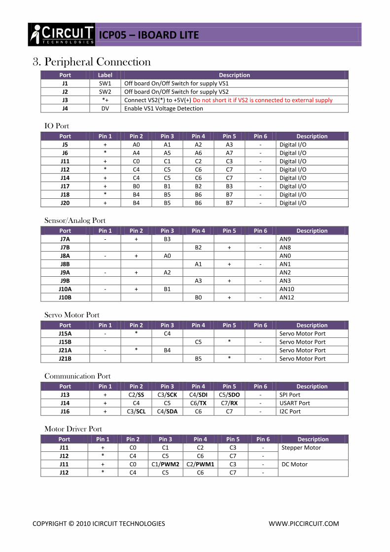
3. Peripheral Connection Port Label Description
J1 SW1 Off board On/Off Switch for supply VS1
J2 SW2 Off board On/Off Switch for supply VS2
J3 *+ Connect VS2(*) to +5V(+) Do not short it if VS2 is connected to external supply
J4 DV Enable VS1 Voltage Detection
IO Port
Port Pin 1 Pin 2 Pin 3 Pin 4 Pin 5 Pin 6 Description
J5 + A0 A1 A2 A3 - Digital I/O
J6 * A4 A5 A6 A7 - Digital I/O
J11 + C0 C1 C2 C3 - Digital I/O
J12 * C4 C5 C6 C7 - Digital I/O
J14 + C4 C5 C6 C7 - Digital I/O
J17 + B0 B1 B2 B3 - Digital I/O
J18 * B4 B5 B6 B7 - Digital I/O
J20 + B4 B5 B6 B7 - Digital I/O
Sensor/Analog Port
Port Pin 1 Pin 2 Pin 3 Pin 4 Pin 5 Pin 6 Description
J7A - + B3 AN9
J7B B2 + - AN8
J8A - + A0 AN0
J8B A1 + - AN1
J9A - + A2 AN2
J9B A3 + - AN3
J10A - + B1 AN10
J10B B0 + - AN12
Servo Motor Port
Port Pin 1 Pin 2 Pin 3 Pin 4 Pin 5 Pin 6 Description
J15A - * C4 Servo Motor Port
J15B C5 * - Servo Motor Port
J21A - * B4 Servo Motor Port
J21B B5 * - Servo Motor Port
Communication Port
Port Pin 1 Pin 2 Pin 3 Pin 4 Pin 5 Pin 6 Description
J13 + C2/SS C3/SCK C4/SDI C5/SDO - SPI Port
J14 + C4 C5 C6/TX C7/RX - USART Port
J16 + C3/SCL C4/SDA C6 C7 - I2C Port
Motor Driver Port
Port Pin 1 Pin 2 Pin 3 Pin 4 Pin 5 Pin 6 Description
J11 + C0 C1 C2 C3 - Stepper Motor
J12 * C4 C5 C6 C7 -
J11 + C0 C1/PWM2 C2/PWM1 C3 - DC Motor
J12 * C4 C5 C6 C7 -

ICP05 – IBOARD LITE
COPYRIGHT © 2010 ICIRCUIT TECHNOLOGIES WWW.PICCIRCUIT.COM
LCD Port
Port Pin 1 Pin 2 Pin 3 Pin 4 Pin 5 Pin 6 Description
J19 - + VO B0/RS B1/RW B2/E LCD Command Port
J22 B4/D4 B5/D5 B6/D6 B7/D7 + B3/L- LCD Data Port

ICP05 – IBOARD LITE
COPYRIGHT © 2010 ICIRCUIT TECHNOLOGIES WWW.PICCIRCUIT.COM
Disclaimer
iCircuit Technologies has an ongoing policy to improve the performance and reliability of their
products; we therefore reserve the right to make changes without notice. The information
contained in this data sheet is believed to be accurate however we do not assume any responsibility
for errors or any liability arising from the application or use of any product or circuit described
herein. This data sheet neither states nor implies warranty of any kind, including fitness for any
particular application.
Copyright Notice
The copyright in this document is owned by, iCircuit Technologies. No part of parts hereof may be
reproduced, distributed, republished, displayed, broadcast, hyperlinked or transmitted in any
manner or by any means or stored in an information retrieval system without the prior written
permission of iCircuit Technologies.
Any liability from defect or malfunction is limited to the replacement of product ONLY, and does
not include labour or other incurred corrective expenses.
Using or continuing to use these devices hereby binds the user to these terms.
CONTACT INFORMATION
For further information or technical assistance please contact:
Web: http://www.piccircuit.com Email: [email protected]