Embed Size (px)
Citation preview

Installation, Operation & Application GuideFor more information on our complete range of American-made products – plus wiring diagrams, troubleshooting tips and more, visit us at www.icmcontrols.com
ICM325HNHead Pressure Control with Optional
Heat Pump OverrideTemperature sensitive control regulates head pressure

Specifications................................................................................................... .1
Connections.for.ICM325HN.at.120/208/240.VAC............................................. .2
Connections.for.ICM325HN.at.480.VAC........................................................... .3
Connecting.the.Probe...................................................................................... .4
Connections.for.Air.Conditioning.Only............................................................ . 4
Connections.for.Heat.Pump.Systems.............................................................. .5
Mode.of.Operation........................................................................................... .6
Setting.the.Cutout.Speed................................................................................ .7
Setting.the.Hard.Start.Time............................................................................. .7
Troubleshooting............................................................................................... .8
Appendices...................................................................................................... .9
ICM325HN.Typical.Installation.......................................................................... .9
Table of Contents
Installation of the ICM325HN shall be performed by trained technicians only. Adhere to all local and national electric codes. Disconnect all power to the system before making any connections.
Caution!
�
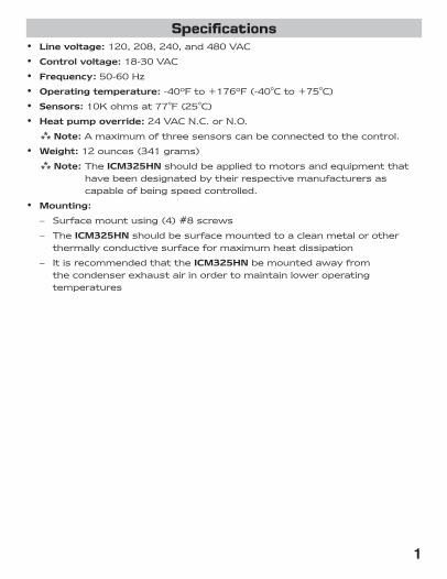
•. Line voltage:.120,.208,.240,.and.480.VAC
•. Control voltage:.18-30.VAC
•. Frequency:.50-60.Hz
•. Operating temperature:.-40ºF.to.+176ºF.(-40°C.to.+75°C)
•. Sensors:.10K.ohms.at.77°F.(25°C)
•. Heat pump override:.24.VAC.N.C..or.N.O.
.Note:.A.maximum.of.three.sensors.can.be.connected.to.the.control.
•. Weight:.12.ounces.(341.grams)
.Note:.The.ICM325HN.should.be.applied.to.motors.and.equipment.that.have.been.designated.by.their.respective.manufacturers.as.capable.of.being.speed.controlled.
• Mounting:.
. –. Surface.mount.using.(4).#8.screws
. –. The.ICM325HN.should.be.surface.mounted.to.a.clean.metal.or.other.thermally.conductive.surface.for.maximum.heat.dissipation
. –. It.is.recommended.that.the.ICM325HN.be.mounted.away.from.the.condenser.exhaust.air.in.order.to.maintain.lower.operating.temperatures
Specifications

�
Connections for ICM325HN at 120/208/240 VAC1.. Remove.power.from.system.2.. Field.install.a.wire.from.Line 1.wire.to.Line 1.terminal.3.. Cut.Line 2.wire;.affix.motor.side.to.Motor 2.terminal.and.line.side.to.Line 2.
terminal.4.. Make.24.VAC,.probe.(see.Page.4).and.HP.(see.Page.5).connections.5.. Verify.wiring.is.correct.6.. Power.up.system.and.check.operation.
PSC Fan
Motor
Run Capacitor
Line1
120/240 VAC
Line2
Motor2
PSC Fan
Motor
Run Capacitor
Field Installed
WireTypical condenser fan with ICM325HN installed
120/208/240 VAC
Typical condenser fan
120/208/240 VAC

�
1.. Remove.power.from.system.2.. Field.install.a.wire.from.Line 1.wire.to.Line 1.terminal.3.. Cut.Line 2.wire;.affix.motor.side.to.Motor 2.terminal.and.line.side.to.Line 2.
terminal.4.. Make.24.VAC,.probe.(see.Page.4).and.HP.(see.Page.5).connections.5.. Verify.wiring.is.correct.6.. Power.up.system.and.check.operation.
Connections for ICM325HN at 480 VAC
PSC Fan
Motor
Run Capacitor480 VAC
Typical condenser fan
Line1
480 VAC
Line2
Motor2
PSC Fan
Motor
Run Capacitor480 VAC
Field Installed
Wire
Typical condenser fan with ICM325HN installed

�
Connecting the Probe
Example
1..Install.the.temperature.probe.several.bends.into.the.condenser..It.can.be.attached.to.the.U-bend.or.placed.between.the.fins.in.the.upper.1/3.of.the.condenser.(see.Page.9.for.more.information).
. .Note:.The.response.of.the.system.can.be.fine.tuned.by.repositioning.the.probe.
2..Connect.the.two.wires.from.the.sensor.to.the.terminal..block.where.it.is.marked.PROBE S1..If.additional.probes.are.necessary.for.multiple.refrigerant.circuits,.they.may.be.attached.to.terminals.marked.PROBE S2.and.PROBE S3.
. .Note:.The.control.will.respond.to.the.probe.that.senses.the.highest.temperature.
Connections for Air Conditioning Only1..For non-heat pump applications,.the.heat.pump.select.jumper.must.
be.in.the.Default.(N.O.).position,.and.the.HP.terminals.must.be.left.unconnected.
2..Set.the.Cutout.Speed.and.the.Hard.Start.Time.to.the.appropriate.positions.for.they.type.of.motor.you.have.(See.Page.7).
Temperature Probe24 VAC
Additional Probes
Probe S1
HPHeat Pump Select Jumper Default Position

�
1.. The.Heat Pump.terminals.accept.the.24.VAC.signal.from.the.reversing.valve.holding.coil..Make.a.parallel.connection.from.the.reversing.valve.to.the.HP.terminals.
. .Note:.Do not apply a voltage higher than 30 VAC to the HP terminals.
2.. If.the.Heat Pump.is.in.the.Heating.mode.and.the.reversing.valve.is.energized,.then.the.Heat Pump Select.jumper.must.be.in.the.Default.(N.O.).position.
3.. If.the.Heat Pump.is.in.the.Heating.mode.and.the.reversing.valve.is.not.energized,.then.the.Heat Pump Select.jumper.must.be.in.the.N.C..position.
Connections for Heat Pump Systems
N.O.
N.C.
Temperature Probe
24 VAC Connect Parallel to 24 VAC Reversing Valve
Additional Probes
Probe S1
HPHeat Pump Select Jumper Default Position

�
Normal Function
With.probe.temperatures.above.100°F,.the.control.applies.full.voltage.to.the.motor..The.green.light.is.illuminated.(full.speed.LED).
With.probe.temperatures.between.70°F.and.100°F,.the.motor.speed.is.proportional.to.the.probe.temperature..The.yellow.light.is.illuminated.(variable.speed.LED).
When.the.motor.starts.at.temperatures.between.70°F.and.100°F,.it.will.hard.start.for.the.length.of.time.dictated.by.the.hard.start.dial.setting..After.the.hard.start.time.has.elapsed,.the.motor.speed.is.controlled.by.the.probe.temperature.
As.the.temperature.being.sensed.decreases,.the.output.voltage.decreases..The.output.voltage.may.decrease.to.the.determined.cutout..speed.dictated.by.the.cutout.speed.dial..Upon.reaching.the.cutout.speed.setting,.the.output.voltage.goes.to.zero.volts.
System.restart.will.occur.when.the.temperature.exceeds.70°F.
With.probe.temperatures.below.70°F,.the.motor.remains.off..The.green.light.and.the.yellow.light.are.off.
Heat Pump Bypass Operation
Heat.pump.bypass.mode.runs.the.fan.at.full.speed.when.the.system.is.operating.in.heat.mode..This.moves.as.much.air.as.possible.across.the.condenser.coil.
If.the.heat.pump.select.jumper.is.in.the.N.O..position,.and.24.VAC.is.applied.to.the.HP.terminals,.the.motor.will.be.brought.to.full.speed.
If.the.heat.pump.select.jumper.is.in.the.N.C..position,.and.24.VAC.is.not.present.at.the.HP.terminals,.the.motor.will.be.brought.to.full.speed..
A.separate.relay.is.not.needed.
Mode of Operation

�
Setting the Cutout Speed
The.cutout.speed.dial.adjusts.the.motor.voltage.range..Set.the.cutout.voltage.dial.according.to.the.type.of.motor.you.have.
Sleeve Bearing Motors:Set.the.cutout.speed.dial.to.the.middle.of.the.sleeve.bearing.range..In.this.range,.the.motor.can.run.down.approximately.40-50%.of.the.full.line.voltage,.which.allows.sufficient.RPMs.for.cooling.and.lubrication.
CAUTION!:. .With.sleeve.bearing.motors,.it.is.important.not.to.adjust.outside.the.sleeve.bearing.range.or.bearing.failure.may.result.
Ball Bearing Motors:.Set.the.cutout.speed.dial.to.the.MIN.position.in.the.ball.bearing.range..This.position.offers.the.greatest.range.of.speed.control..At.the.MIN.setting.the.motor.can.run.down.to.approximately.20-30%.of.the.full.line.voltage.
.Note:.After.starting.at.the.recommended.settings.for.either.sleeve.or.ball.bearing.motors,.you.can.fine.tune.the.cutout.speed.to.achieve.the.desired.results.
During.the.Hard Start.mode,.full.voltage.is.applied.to.the.motor.during.startup.to.overcome.windmilling.and.to.lubricate.the.bearings.
The.position.of.the.hard.start.dial.determines.the.time.period.of.the.hard.start.mode..The.dial.can.be.adjusted.between.0.1.second.and.approximately.5.seconds.
Set.the.hard.start.dial.according.to.the.type.of.motor.you.have..If.you.have.a.ball bearing motor,.set.the.hard.start.dial.to.the.MIN.position..If.you.have.a.sleeve bearing motor,.set.the.hard.start.dial.to.the.middle.of.the.sleeve.bearing.range.
After.you.begin.at.the.recommended.setting,.you.can.fine.tune.the.hard.start.time.within.the.recommended.range.for.the.type.of.motor.you.have.
It.is.recommended.that.you.use.the.minimum.possible.hard.start.time.to.avoid.blowing.too.much.cold.air.over.the.condenser.
Hard Start.mode.is.activated.when.24.VAC.is.applied.(or.disconnected.and.re-applied).or.the.probe.temperature.increases.to.above.70°F..The.hard.start.mode.applies.full.voltage.to.the.motor.for.the.set.time.period..Afterwards,.the.motor.speed.is.dictated.by.the.temperature.sensor(s).
Setting the Hard Start Time

�
Symptom ProblemUnit.fails.to.start. The.sensor.may.not.be.connected.or.it.is.defective.
With.the.probe.disconnected,.use.an.ohmmeter.to.measure.the.resistance.between.the.probe.wires..It.should.match.the.chart.in.Appendix.B.(see.Page.9)..If.you.read.an.OPEN.or.SHORT,.replace.the.sensor.
Fuse.and/or.circuit.blows
The.unit.has.been.miswired.and.may.be.permanently.damaged.
The.fan.cycles.from.full.ON.to.full.OFF.with.little.or.no.modulation
Turn.OFF.the.control.circuit.power.(24.VAC)..Re-apply.24.VAC.power.and.confirm.hard.start.operation..Reduce.the.hard.start.period.to.the.minimum.setting.required.to.accelerate.the.fan..Excessive.hard.starting.causes.large.pressure.drops.by.running.too.much.cold.air.over.the.condenser.Should.the.cycling.persist,.move.the.probe.up.several.bends.into.the.condenser.to.increase.the.sensitivity.to.condensing.temperature.Adjust.probe.location..Fine.tune.cutout.adjustment.
The.fan.does.not.come.on.at.all
Using.an.AC.voltmeter,.measure.the.voltage.between.the.24.VAC.terminals..It.should.read.approximately.24.volts.Measure.the.line.voltage.between.LINE 1.and.LINE 2.to.confirm.that.the.line.voltage.is.present.Remove.the.thermistor.probe.from.the.terminal.block.and.measure.its.resistance.at.ambient.temperature..Compare.your.reading.at.the.appropriate.temperature.in.Appendix.B.(see.Page.9).to.see.if.the.actual.resistance.approximates.the.listed.value..Next,.hold.the.probe.in.your.hand.and.confirm.that.the.resistance.decreases.Place.a.temporary.jumper.across.the.S2.or.S3.terminals..Fan.should.run.at.full.speed..If.it.does,.recheck.probe.connection.and.verify.probe.is.operating.correctly.
The.high.pressure.switch.trips.off
Move.the.probe.further.into.the.condenser.where.the.temperature.is.higher..This.will.produce.a.higher.fan.RPM.and.will.decrease.the.head.pressure.Fine.adjust.the.cutout.and.hard.start.settings.
Troubleshooting

�
Mounting a sensor into the condenser vs. mounting it on the liquid line
When.a.sensor.is.mounted.into.the.condenser,.the.control.responds.more.rapidly.to.changes.in.head.pressure.than.when.it.is.mounted.on.the.liquid.line..This.is.especially.true.for.high.efficiency.condensers.
When.the.sensor.is.mounted.on.the.liquid.line,.the.control.responds.more.slowly.and.the.results.can.be.a.fan.that.cycles.on.and.off.
Whenever.possible,.it.is.preferable.to.mount.the.sensor.in.the.upper.1/3.of.the.condenser.instead.of.mounting.it.on.the.liquid.line.(see.illustration.below).
Temperature vs. Probe Resistance
°C °F Resistance (KΩ)0° 32° 32.7
5° 41° 25.4
10° 50° 19.9
15° 59° 15.7
20° 68° 12.5
25° 77° 10.0
30° 86° 8.1
35° 95° 6.5
40° 104° 5.3
45° 113° 4.4
50° 122° 3.6
Appendix A Appendix B
ICM325HN Typical Installation
Condenser
Sensor
Sensor
Sensor
ICM325HN can monitor
two additional condensers
Motor1
Motor2
Reversing Valve for Heat Pump
T-Stat
Control Transformer
Line 2
Line Voltage
Terminal to be used for 480 VAC
Line 1

���� William Barry Blvd., North Syracuse, NY �����(Toll Free) 800-365-5525 (Phone) 315-233-5266 (Fax) 315-233-5276
www.icmcontrols.com
ONE-YEAR LIMITED WARRANTYThe.Seller.warrants.its.products.against.defects.in.material.or.workmanship.for.a.period.of.one.(1).year.from.the.date.of.manufacture..The.liability.of.the.Seller.is.limited,.at.its.option,.to.repair,.replace.or.issue.a.non-case.credit.for.the.purchase.prices.of.the.goods.which.are.provided.to.be.defective..The.warranty.and.remedies.set.forth.herein.do.not.apply.to.any.goods.or.parts.thereof.which.have.been.subjected.to.misuse.including.any.use.or.application.in.violation.of.the.Seller’s.instructions,.neglect,.tampering,.improper.storage,.incorrect.installation.or.servicing.not.performed.by.the.Seller..In.order.to.permit.the.Seller.to.properly.administer.the.warranty,.the.Buyer.shall:.1).Notify.the.Seller.promptly.of.any.claim,.submitting.date.code.information.or.any.other.pertinent.data.as.requested.by.the.Seller..2).Permit.the.Seller.to.inspect.and.test.the.product.claimed.to.be.defective..Items.claimed.to.be.defective.and.are.determined.by.Seller.to.be.non-defective.are.subject.to.a.$30.00.per.hour.inspection.fee..This.warranty.constitutes.the.Seller’s.sole.liability.hereunder.and.is.in.lieu.of.any.other.warranty.expressed,.implied.or.statutory..Unless.otherwise.stated.in.writing,.Seller.makes.no.warranty.that.the.goods.depicted.or.described.herein.are.fit.for.any.particular.purpose.
LIA221-1