Embed Size (px)
Citation preview

Ice & RainTrainer

- The Hangar Dart series of simulators -
Page 2Ice & Rain System Trainer
INFORMATION & OPERATIONS MANUAL
Component Location
PropellerAnti-iceComponents
Wing boot anti-ice pneumatic compo-nents
Pitot tube anti-ice
WindshieldAnti-iceComponents
Control andIndicatingComponents
Locking Casters
110 VAC plug

- The Hangar Dart series of simulators
Page 3Ice & Rain System TrainerINFORMATION & OPERATIONS MANUAL
Description and operationIce & Rain Trainer Description
The IRT-R5 is a fully functional Ice and Rain Protection system. It incorpo-
rates an anti-ice thermal blanket on the propeller, heated Pitot tube, anti-ice
windshield, pneumatic wing de-ice boot system, electric windshield wiper,
and all necessary components and control devices providing an excellent
trainer representative of a typical aircraft ice and rain system. Extreme cau-
tion should be observed at all times when activating this trainer. Students
should not operate this system without instruction and supervision.
A 24 volt DC power supply activates the various components of the Ice &
Rain trainer to allow operation as well as troubleshooting. Faults that have
been integrated into the trainer to allow the instructor to challenge the stu-
dent.
In addition certain safety features have been incorporated to allow operation
of these systems during ground operation. Please note that operating the
various systems during ground operation of the aircraft would not be allowed.
The anti ice windshield would never be cycled on during ground operations
as the temperature of the windshield could cause distortion in the field of vi-
sion for the pilot. The pitot heat is typically selected on just prior to takeoff
as the heat generated is considerable. The students need to understand the
operation of these units without cooling air provided by flight would require
caution on operational aircraft.
The vacuum system in a typical aircraft is always suppling either vacuum or
pressure to various instruments and aircraft systems. The pressure side of
the vacuum pump on the IRT-R5 when the de-ice boots are cycled is closed
and therefore loads the pump, the RPM of the pump will change significantly
when the boot is inflated, this is considered normal.

- The Hangar Dart series of simulators
Page 4Ice & Rain System TrainerINFORMATION & OPERATIONS MANUAL
Description and operationPropeller thermal blanket
The propeller is guarded from ice accumulation before entering icing con-
ditions by selecting the propeller de-ice system on. In addition the propeller
thermal blanket can shed ice if the ice build up begins before the propeller
de-ice is selected on.
When the propeller de-ice is selected on the circuit breaker provides power
to the on off switch which routes power to the propeller de-ice control mod-
ule. The control module will cycle current to the electrically heated thermal
blanket that is glued to the propeller blade. The thermal blanket has two
elements embedded into the rubber plys that warm due to electrical re-
sistance. There is an "inner" and "outer" heating element. The control box
will start the primary heating cycle by heating the outboard element first.
This allows the centrifugal forces acting on the propeller blade to sling the
ice that is located closest to the tip to depart the propeller blade first. The
controller will after a pre determined time discontinue heating the outboard
section and heat the inboard section of the propeller thermal blanket. As
the Ice melts the centrifugal forces will sling the ice located on the inboard
section of the boot. When this second cycle completes the propeller should
be clear of ice. When the propeller completes its heating cycle on the initial
engine on a multi engine aircraft the prop control will then cycle the second
engine in the manner. The IRT has a twin engine controller, this provides
a cooling cycle for the propeller boot. The propeller de-ice controller will
repeat the cycle continuously until it is selected off by the pilot. Current is
provided to the thermal blanket by a slip ring and brush block assembly.
The slip ring rotates with the propeller and the brush block remains station-
ary. The brush blocks are in three separate modules so they can be re-
moved or replaced independent of each other.

- The Hangar Dart series of simulators
Page 5Ice & Rain System TrainerINFORMATION & OPERATIONS MANUAL
Description and operation
PropDe-ice Gauge
Prop De-ice switch
PropellerThermalBlanket
PropDe-ice BrushBlock
PropDe-ice Controller

- The Hangar Dart series of simulators
Page 6Ice & Rain System TrainerINFORMATION & OPERATIONS MANUAL
Description and operationPneumatic Wing Boot Description
The pneumatically operated wing boot system is controlled by the pilot
when ice forms on the leading edges. Ice accumulation is required before
the boots are selected on. The ice must be of a minimum thickness so when
the boots expand the ice will break. If the ice is to thin when the boots are
cycled it may not break and this could lead to more ice accumulation caus-
ing the ice to be harder to shed from the airfoil. Once the pilot depresses
the momentary "wing ice" switch the boots will cycle through the inflation,
deflation, vacuum process automatically. The boots do not cycle again until
the pilot determines another cycle is required.
With activation of the wing de-ice switch, the deflate valve closes and
vacuum is removed from the boot. Power is supplied to the boot control
valve allowing pump pressure to flow to the boot. The inflating of the boot
breaks the ice from the leading edge of the wing. The wing de-ice light will
illuminate during the inflation cycle. Once the boot timer has reached the
seven second duration the timer removes current to the de-ice control valve
allowing the trapped air in the boot to exhaust to the atmosphere through
the deflate valve. When 2 PSI is reached in the boot the deflate valve will
energize the vacuum valve, close the exhaust valve apply vacuum to the
boot holding the boot tight to the wing. If the boot is not held tight against
the wing the aerodynamic forces acting on it will pull the boot away as if it
were partially inflated.

- The Hangar Dart series of simulators
Page 7Ice & Rain System TrainerINFORMATION & OPERATIONS MANUAL
Description and operation
Wing boot pres-sure switches
Wing boot switch and fail light
Wing boot Pressure Gauge
Wing boot Adjustable Vacuum relief and Filter
Wing boot controller
Wing boot Timer
Vacuum pump
Wing boot

- The Hangar Dart series of simulators
Page 8Ice & Rain System TrainerINFORMATION & OPERATIONS MANUAL
Description and operationHeated windshield description
The heated windshield has a high and low position and is designed to heat
the windshield so ice cannot form on the windshield and obstruct the pilots
vision. The windshield contains two separate heating elements and one re-
sistance sensor. When power is applied to the windshield the windshield will
begin to heat. As the windshield heats, the embedded sensor wire located in
the lower corner of the windshield will change resistance. The windshield con-
troller looks at the resistance of the windshield and determines the duration of
the on or powered cycle by that resistance. When the windshield resistance
reaches the predetermined point the controller cycles the windshield off. The
high windshield cycle operates and is controlled in the same manner.
When the windshield is selected to high it does not get hotter but has more
current to stay at temperature. The out side atmosphere will dictate the wind-
shield settings the pilot will select.

- The Hangar Dart series of simulators
Page 9Ice & Rain System TrainerINFORMATION & OPERATIONS MANUAL
Description and operation
Windshield Temperature Sensor
Windshield high and Low switch
Windshield Amperes Gauge
Windshield Temperature Selector
Windshield Temperature Controller

- The Hangar Dart series of simulators
Page 10Ice & Rain System TrainerINFORMATION & OPERATIONS MANUAL
Description and operationPitot tube description
The pitot tube is an electrically heated tube that prevents the formulation of
ice ensuring the proper air data is supplied to the various instruments. To pre-
vent ice from accumulating on the tube a resistance coil is built into the tube.
By switching on the pitot tube, current is provided to the element causing it
to generate heat. The pitot tube should never be turned on and left on during
ground operation on operational aircraft. The GATS systems trainer is spe-
cially design so this is possible on a controlled basis.
Pitot tube switch
Pitot tube

- The Hangar Dart series of simulators
Page 11Ice & Rain System TrainerINFORMATION & OPERATIONS MANUAL
Description and operation
Windshield wiper descriptionThe windshield wiper is designed to improve the pilots visibility during ground
operation, take off, and landing phases of flight. The wiper is controlled by a
switch installed on the panel. In addition the wiper has a self parking feature
that will return the wiper to specific location when the switch is selected off.
Wiper switch
Wiper assembly

- The Hangar Dart series of simulators -
Page 12Ice & Rain System Trainer
INFORMATION & OPERATIONS MANUAL
System Set Up POWER OFFTRAINER SET - UP
Position the trainer in a stable location and provide room for student access
around the unit. Lock the brakes on the casters .
CAUTION; When moving the trainer have no less then 3 people. The unit is
top heavy and will want to fall to the rear. You must support the unit and not
allow the unit to tip. Never push the unit with the back board facing in the di-
rection of travel. ALWAYS push the unit from its side and traveling to its side.
Top heavy never push in this direction!
Locking casters

- The Hangar Dart series of simulators -
Page 13Ice & Rain System Trainer
INFORMATION & OPERATIONS MANUAL
POWER ONSYSTEM DEMONSTRATION
After completion of the setup procedures the trainer functions as follows:
Power-Up the IRT-R5 by selecting the master switch to the “On” position. This provides the necessary 24 volts DC required for operation of the air-
craft systems.
Pneumatic boot operation, set the fault switch position as follows FS1 Down FS11 Down
Select the pump switch on, the vacuum pump will start rotating and both pump pressure and vacuum will be supplied the boot system. Excess vacuum pump pressure is routed to an exhaust hose pointed directly at the vacuum pump. This cooling air will help cool the pump. Vacuum pumps are designed to be cooled in flight by the cooling air rushing throughout the engine cowling. The operation of the vacuum pump shall be held to a maximum of 5 minutes. Allow the pump to cool before starting another pump on cycle.
Set the vacuum pump as follows;Select the vacuum switch on (up). Check the vacuum gauge, the needle should be in the green arc. If adjustment is necessary bend the lock tabs so the roll pin on the bottom can be rotated. In to increases and out decreases. Once the pressure is set bend the lock tabs back into position.
CAUTION; The vacuum pump gets very hot while in operation and will be after operation, DO NOT TOUCH the pump during these times.
AdjustmentVacuum Gauge
Vacuum Switch

- The Hangar Dart series of simulators -
Page 14Ice & Rain System Trainer
INFORMATION & OPERATIONS MANUAL
POWER ON
Hot windshield operation, set the fault switch position as follows
FS2 Up FS3 Up FS4 Up FS7 Up FS8 Up FS9 Up
Due to the very high amperage requirements of a heated windshield a poten-tiometer has been installed to replicate the increased resistance in the heat sensor normally generated by the heating elements embedded in the wind-shield. Additionally the windshield can be operated by carefully heating the sensor elements embedded in the windshield with a heat gun. The IRT-R5 connections from the controller to the windshield are insulated to prevent a complete electrical path to the heating elements. Voltage checks can still be taken at the insulated windshield LP terminal locations.
Windshield low operation;
With the master switch on select the windshield temperature simulator knob all the way to the counterclockwise position. Press the windshield low switch to turn on the windshield. Check the windshield amps, they should be ap-proximately 26 amps. Slowly rotate the windshield temperature selector to-wards the "H" position clockwise and the windshield will cycle off. You have increased the resistance sensed by the windshield controller with the potenti-ometer simulating the windshield as it heats.
The windshield controller senses the changes in resistance induced by the windshield temperature control. Rotate the windshield temperature control towards the cold or "C" position and cycle the windshield off. Rotating the temperature control counter clockwise will signal a lowering of the resistance of the windshield sensor element as if it was cooling and again the windshield
WindshieldTemperature Control
- The Hangar Dart series of simulators -
Page 15Ice & Rain System Trainer
INFORMATION & OPERATIONS MANUAL
POWER ONHot windshield operation in high requires the windshield to already be op-
erating in the low position. There are two different heating elements em-bedded in the windshield so for the windshield to operated in the high posi-tion they must both be heated. Rotate the windshield temperature simulation control counterclockwise until the amperage gauge reads amperage again and then select high by depressing the windshield high push button switch in. The amperage gauge will read approximately 50 amps.
You may also cycle the windshield by heating the embedded sensor in the windshield. First set the windshield temperature knob so that the windshield amperage gauge initially shows indication, this may require rotating the knob back an forth several times. This will reduce the heating of the wind-shield. Glass is a poor conductor so it will take some time for the windshield to warm enough for the embedded elements to change resistance and shut the windshield off. In addition the windshield heating elements generate heat from inside the windshield instead of heating from the outside. Carefully wave the heating gun back and forth continually and remove the heat gun from time to time to allow the heat to saturate the glass then return the heat gun and continue this sequence until the amperage gauge indicates zero. This indicates the windshield controller has sensed a change in the sensor resistance and cycled the windshield off. This may take up to 5 minutes to heat saturate the glass from the outside with the heat gun. The windshield will cycle back on when the glass becomes cool enough but this will take some time at room temperature. To return the windshield to operation rotate the temperature knob.
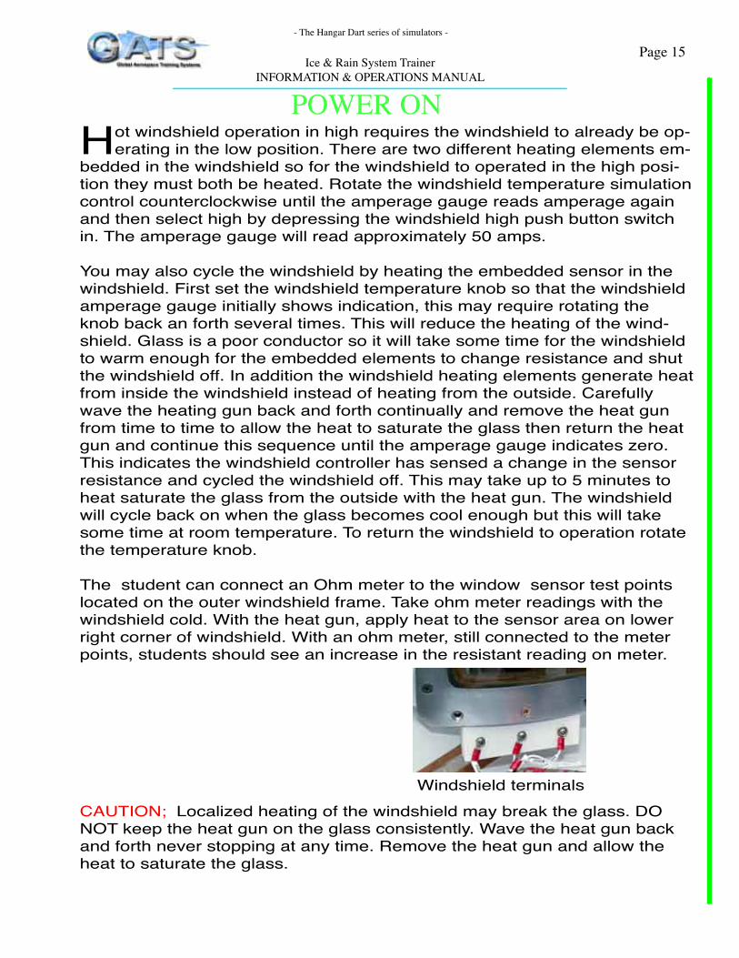
The student can connect an Ohm meter to the window sensor test points located on the outer windshield frame. Take ohm meter readings with the windshield cold. With the heat gun, apply heat to the sensor area on lower right corner of windshield. With an ohm meter, still connected to the meter points, students should see an increase in the resistant reading on meter.
CAUTION; Localized heating of the windshield may break the glass. DO NOT keep the heat gun on the glass consistently. Wave the heat gun back and forth never stopping at any time. Remove the heat gun and allow the heat to saturate the glass.
Windshield terminals
- The Hangar Dart series of simulators -
Page 16Ice & Rain System Trainer
INFORMATION & OPERATIONS MANUAL
POWER ON
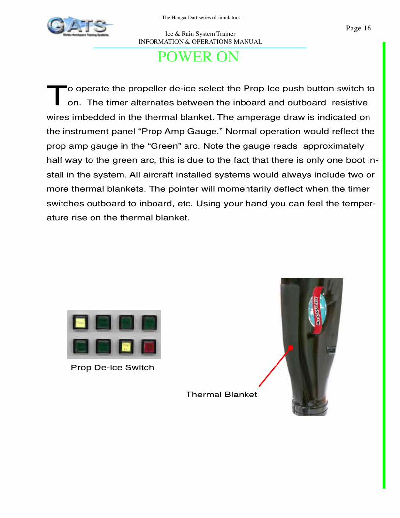
To operate the propeller de-ice select the Prop Ice push button switch to
on. The timer alternates between the inboard and outboard resistive
wires imbedded in the thermal blanket. The amperage draw is indicated on
the instrument panel “Prop Amp Gauge.” Normal operation would reflect the
prop amp gauge in the “Green” arc. Note the gauge reads approximately
half way to the green arc, this is due to the fact that there is only one boot in-
stall in the system. All aircraft installed systems would always include two or
more thermal blankets. The pointer will momentarily deflect when the timer
switches outboard to inboard, etc. Using your hand you can feel the temper-
ature rise on the thermal blanket.
Prop De-ice Switch
Thermal Blanket

- The Hangar Dart series of simulators -
Page 17Ice & Rain System Trainer
INFORMATION & OPERATIONS MANUAL
POWER ON
The windshield wiper is operated as follows, to reduce scratching of the
windshield it is recommended that the windshield be cleaned prior to
use of the wiper. Depress the windshield wiper switch to activate wiper in
“slow” mode. The high speed setting has been disabled to prevent a possible
hazard associated with wiper moving at high setting and student contact.
When wipers are turned off they will move into the “parked” position.
CAUTION; The windshield motor is powerful ensure all personnel are clear
of the windshield area before initiating the wiper system to on.
Wiper Switch
Wiper assembly shown in the parked Position

- The Hangar Dart series of simulators -
Page 18Ice & Rain System Trainer
INFORMATION & OPERATIONS MANUAL
POWER ON
The pitot heat is activated by depressing the “Pitot” switch. This will
provide a complete path to the embedded resistant wires located in
the Pitot tube. A “Time Delay” relay is incorporated in the circuit to remove
power from the Pitot heat element after approximately 1.75 minutes. Re-
move the pitot tube protective cover before heating the tube. For safe oper-
ation of the Pitot tube an in line (series) heat dissipating resistor has been
installed in the simulator base unit. The resistor provides some personnel
and unit protection from the heat generated in the tube.
CAUTION; DO NOT OPERATE PITOT TUBE THOROUGH NUMEROUS
CYCLES. HEAT GENERATED WILL DESTROY UNIT.
Protective coverPitot heat switch
- The Hangar Dart series of simulators -
Page 19Ice & Rain System TrainerINFORMATION & OPERATIONS MANUAL
CurriculumDrawing #30-10-01-1
Pneumatic BootMaster on - System off
# 30-10-01-1 -- Shows the Pneumatic system with Master “On” and power pro-
vided to the buss. The wing ice switch is selected off, the 2 PSI switch is closed
providing power to the de-ice flow control valve on pin "C". The flow control
valve has a vacuum valve (internally) that is open providing vacuum to the boot.
See FCV-1 for the flow control valve operation.
Cautions: Student must exercise caution when doing voltage checks, turn power off for
any continuity checks.
- The Hangar Dart series of simulators -
Page 20Ice & Rain System TrainerINFORMATION & OPERATIONS MANUAL
CurriculumDrawing #30-10-01-2
Pneumatic BootMaster on - Wing de-ice switch ON - System Normal
Reference power wires are orange
# 30-10-01-2 -- Shows the Pneumatic system with the master “On” and power
provided to the buss from the 24 volt power supply through a circuit breaker.
With activation of the wing de-ice switch (momentary), the deflate valve opens
and vacuum is removed from the boot. Power is supplied to the 10 psi switch.
(normally closed), then powering the De-ice flow control valve. In addition the
Pump cooling valve is de-energize to make all available pump air for the boot.
See FCV-2 for the flow valve configuration.
Cautions:
Student must exercise caution when doing voltage checks, turn power off for
any continuity checks.

- The Hangar Dart series of simulators -
Page 21Ice & Rain System TrainerINFORMATION & OPERATIONS MANUAL
CurriculumDrawing #30-10-01-3
Pneumatic BootMaster on - Wing de-ice switch ON
System failed - overpressure.Reference power wires are orange
# 30-10-01-3 -- Shows the Pneumatic system with the master “On” and power
provided to the buss, from the 24 volt power supply through a circuit breaker.
With activation of the wing de-ice switch (momentary), the deflate valve opens
and vacuum is removed from the boot. Power is supplied to the 10 psi switch.
The normally closed 10 PSI switch is closed due to an overpressure on the
boot system and has tripped the boot fail light relay. The De-ice system is de-
signed that in the case of a boot overpressure condition the warning lamp will
have to be extinquished by the pilot by pressing the fail indicator, disconnect-
ing the ground from the relay. The flow control valve has returned to is normal
vacuum applied position.
See FCV-3 for the flow valve configuration.
Cautions:
Student must exercise caution when doing voltage checks, turn power off for
any continuity checks.

- The Hangar Dart series of simulators -
Page 22Ice & Rain System TrainerINFORMATION & OPERATIONS MANUAL
CurriculumDrawing #30-40-10-1
Windshield de-iceMaster on - Windshield de-ice switch low ON
The master switch on with the windshield low switch on and the windshield not
yet up to temperature to cycle.
# 30-40-01-1 -- Shows power supplied from the buss to the windshield control-
ler and windshield low relay. The windshield low switch is pushed in and powers
the windshield controller. The indicator lamp is illuminated and the controller is
energizing the low relay which connects the buss supplying power to the low
terminal on the windshield.
Cautions:
Student must exercise caution when doing voltage checks, turn power off for
any continuity checks.

- The Hangar Dart series of simulators -
Page 23Ice & Rain System TrainerINFORMATION & OPERATIONS MANUAL
CurriculumDrawing #30-40-10-2
Windshield de-iceMaster on - Windshield de-ice switch on high
The master switch on with the windshield low and high switch on and the wind-
shield not yet up to temperature to cycle.
# 30-40-01-2 -- Shows power supplied from the buss to the windshield control-
ler and windshield low relay. The windshield low switch is pushed in and powers
the windshield controller. The indicator lamp is illuminated and the controller is
energizing the low relay which connects the buss supplying power to the low
terminal on the windshield.
When the high switch is closed power is supplied all the time to the coil on the
windshield high relay. Current is supplied to the windshield high relay contacts
from the output contacts on the low current relay. Current passes through the
contacts on the relay to the high terminal on the windshield. The windshield is
on high hot.
Cautions:
Student must exercise caution when doing voltage checks, turn power off for
any continuity checks.

- The Hangar Dart series of simulators -
Page 24Ice & Rain System TrainerINFORMATION & OPERATIONS MANUAL
CurriculumDrawing #30-40-10-3
Windshield de-ice
Master on - Windshield de-ice switch high
Windshield cycling
The master switch on with the windshield low switch on, the windshield high
switch on and the windshield at temperature to cycle.
# 30-40-01-3 -- The controller has sensed a change in the resistance of the
embedded sensor. The resistance is of sufficient value to trip the windshield
controller to off. The controller cuts power to the low relay witch opens the con-
tacts. The opening of the contacts on the low relay removes power from the
windshield high relay dropping power from both the low and high terminals of
the windshield.
Cautions:
Student must exercise caution when doing voltage checks, turn power off for
any continuity checks.

- The Hangar Dart series of simulators -
Page 25Ice & Rain System TrainerINFORMATION & OPERATIONS MANUAL
CurriculumDrawing #30-30-01-1
Heated pitot tube
Master on - Pitot tube switch on
The master switch is on and the pitot switch on.
# 30-30-01-1 -- The pilot has been advised that he is flying into known icing
conditions and has selected the pitot tube on. The single shot relay is allowing
the heated pitot tube to operate for the ground allotted time.
Cautions:
Student must exercise caution when doing voltage checks, turn power off for
any continuity checks.
NOTE;
The IRT-R5 has a single shot timed relay that would not be found on aircraft.
Additionally the IRT-R5 has an in series resistor to limit the heat generated
by the pitot tube, on any operational aircraft the pitot tube would heat MUCH
FASTER!

- The Hangar Dart series of simulators -
Page 26Ice & Rain System TrainerINFORMATION & OPERATIONS MANUAL
CurriculumDrawing #30-60-01-1
Propeller heat
Master on - Propeller heat switch selected on
The master switch is on and the propeller switch is on.
# 30-60-01-1 -- The pilot has been advised that he is flying into known icing
conditions and has selected the propeller heat on. The outboard section of the
de-ice boot is heating.
Cautions:
Student must exercise caution when doing voltage checks, turn power off for
any continuity checks.
NOTE;

- The Hangar Dart series of simulators -
Page 27Ice & Rain System TrainerINFORMATION & OPERATIONS MANUAL
CurriculumDrawing #30-60-01-2
Propeller heat
Master on - Propeller heat switch selected on
The master switch is on and the propeller switch is on.
# 30-60-01- -- The pilot has been advised that he is flying into known icing
conditions and has selected the propeller heat on. The outboard section of the
de-ice boot has finished its heating cycle and the inboard boot is now heating.
Cautions:
Student must exercise caution when doing voltage checks, turn power off for
any continuity checks.
NOTE;
- The Hangar Dart series of simulators -
Page 28Ice & Rain System TrainerINFORMATION & OPERATIONS MANUAL
CurriculumInstructor Introduced Faults
The instructor may introduce various faults in the system and it will be
the responsibility of the student to determine the malfunction and corrective
action.
FS (fault switch) 1 Pilot Report;
When I select the boot de-ice switch to the on position the wing boot
pulsates and the wing ice light flickers at about the same frequency. The
wing fail light is also on. The boot seems to pop the ice of but not like it
should.
Repair; Drawing # 30-10-01-FS1
The 10 PSI switch has failed and is opening at to low of a pressure
causing the system to oscillate. Power to the cannon plug B pin is re-
ceiving momentary power.
FS 2 Pilot Report;
When I select the windshield to low or high the lights come on but no
amperage is shown on the gauge and it will not de-ice or even defog
the windshield.
Repair; Drawing # 30-40-10-FS2
The wire H40A18 carrying current from the windshield shunt to the wind-
shield low relay is broken and will need replacement.
FS 3 Pilot Report;
When I select the windshield to high it seams to be operating and the
amperage gauge is reading 50 amps but the windshield high lamp is not
illuminated.
- The Hangar Dart series of simulators -
Page 29Ice & Rain System TrainerINFORMATION & OPERATIONS MANUAL
Curriculum
Repair; Drawing # 30-40-10-FS3
The wire H41C18 carrying current from the windshield high relay to the
indicator lamp is broken and will need replacement.
FS 4 Pilot Report;
When I select the windshield heat to either high or low the indicator
lights come on but there is no amperage indication in either high or low
and I hear a clicking sound.
Repair; Drawing # 30-40-10-FS4
The wire H41D18 carrying current from the windshield controller to the
windshield low relay is bad. Replace the wire or terminal.
The clicking heard is the high relay still working but power is provided
to the high relay contacts from the low relay so no power is passing
through the relay contacts, indicator lamps are .
FS 5 Pilot Report;
When I select the wiper on it works fine. When I select the wiper off it
just stops wherever it is located.
Repair; Drawing # 30-40-01-FS5
The wire H50B18 connecting the wiper switch to the park wire is discon-
nected. This disables the park feature on the wiper and it will stop where
ever the wiper is located in its arc.
FS 6 Pilot Report;
When I select the pitot heat on I get no amperage indication but all the
instruments that reference the pitot air keep working so I think it is still
working but I'm not sure.
- The Hangar Dart series of simulators -
Page 30Ice & Rain System TrainerINFORMATION & OPERATIONS MANUAL
CurriculumRepair; Drawing # 30-30-01-FS6
The wire H60D18 connecting the amperage gauge to the shunt is bad
and needs repair. The gauge is not connected to the system but the pitot
tube is operating.
FS 7 Pilot Report;
When I select the windshield heat to either high or low the indicator
lights come on and there is amperage indication in either high or low but
the windshield will not cycle off I have to shut the windshield down man-
ually.
Repair;Drawing # 30-40-10-FS7
The wire H41M18 connecting the sensor to the controller is bad and
needs repair. The controller can not sense the temperature of the wind-
shield so it will not cycle.
FS 8 Pilot Report;
When I select the windshield heat to either high or low the indicator
lights come on but the windshield does not indicate an amperage draw
on the gauge and it is not getting hot
Repair; Drawing # 30-40-10-FS8
The wire H41Q18 connecting the controller to ground is bad and needs
repair. The controller can not operate without a ground.
FS 9 Pilot Report;
When I select the windshield heat to either high or low the indicator
lights come but there is amperage indication only on high. When the
windshield is on low there is no amperage draw.

- The Hangar Dart series of simulators -
Page 31Ice & Rain System TrainerINFORMATION & OPERATIONS MANUAL
CurriculumRepair; Drawing # 30-40-10-FS9
The wire H40B18 connecting the controller to the low terminal on the
windshield is bad and needs repair. The relay is not connected to the
windshield.
FS 10 Pilot Report;
When I select the Prop de-ice on, the system seems to work part of the
time. The indicator light comes on and the amperage gauge indicates
a draw and then goes to zero. Is this normal? Is the timer pausing be-
tween cycles.
Repair; Drawing # 30-60-01-FS10
The wire H30H18 connecting the prop de-ice brush block to the prop
boot is bad. Possibly the wire connection on the brush block assembly is
bad, the brushes are dirty or worn out, or the brushed are misaligned.
FS 11 Pilot Report;When I select the boots to the on position they do not inflate. The wing ice light is on but the boots will not inflate. The fail lamp is not illuminat-ed.
Repair; Drawing # 30-10-01-FS11The wing boot flow control valve is defective and not suppling air pres-sure to the boot. Reference purple wire on drawing 30-10-01-FS1 has no power. The boot fail lamp will not illuminate, it is an overpressure indicator.


![Ice & Rain Protection - SmartCockpit - Airline training … · 2012-06-27 · Airbus A319-320-321 [Ice & Rain Protection] Page 1. Airbus A319-320-321 [Ice & Rain Protection] Page](https://img.pdfslide.us/doc/110x75/5b4fd9987f8b9a1b6e8d1419/ice-rain-protection-smartcockpit-airline-training-2012-06-27-airbus.jpg)