Embed Size (px)
Citation preview

IC Engines and Gas TurbinesDr. Pranab K. Mondal
Department of Mechanical EngineeringIndian Institute of Technology, Guwahati
Lecture - 27CI engine injection systems, Air-cooled and liquid-cooled engines, Modern trends
(Contd.)
We will continue our discursion on IC Engine and today we will discussed about CI
engine injection system, we have started our discursion on CI engine injection system,
but we will continue with that. And then we will briefly discussed about the Air cooled
and liquid cooled engines. So, we have discussed about the, you know we have seen that
compression ignition engine, injection systems can we classified into two categories; one
is air injection system, another is solid injection system.
We have discussed about the air injection system and we have seen that nowadays i it is
obsolete now, because of you know the cost associated with the mix size compression as
well as it running cost. And then we have discussed about the solid injection system
which is further sub classified into three categories common rail system, individual pump
and nozzle in an unit injector.
So, we have discussed about the common rail system. And if I, we try to today we try to
see what are you know disadvantages are associated. I mean what are the disadvantages
associated with this injection system?

(Refer Slide Time: 01:36)
So, if you try to recall, I want to draw the schematic again because last class I have
drawn the schematic just I will try to draw the, this is the engine cylinder I am need to
work out few analytical expression. Then if this is the engine cylinder, so, this is cylinder
and this is nozzle. We will discuss about one by one and if you try to recall that pressure
at the cylinder was P 1.
So, here pressure is P 1 and here pressure is P 2. So, P 2 the pressure at nozzle and P 1 is
the pressure at pressure in the cylinder. Now, if I try to that we need to know what is the
mass flow rate of fuel, because let me tell you in this common rail system we have seen
that this is the common rail in which the pressure is reaming constant.
So, that is the if pressure changes there is the system for we can maintain a constant
pressure by regulating certain amount of well through throttle bulb that is, because the
common rail system is the connected with the high pressure pump. So, the high pressure
pump build up that pressure and essentially to maintain a pressure constant in a common
rail system.
In case, pressure raises above the you know design pressure of the common rail system
then liquid fuel is taken back to the taken back inlet to the common rail system through
throttle bulb. Let us it there is a regulated so, pressure head is constant by pressure
regulating bulb throttle bulb. So, we can see that the pressure we have seen pressure in
the common rail is constant rather this constant pressure; constant pressure is

maintained; constant pressure is maintained by the by a pressure regulating bulb; by a
pressure regulating bulb or by throttling that is what we have seen. Now this is the
maximum pressure under direct control and metering problem is not handled by the high
pressure pump.
So, high pressure pump is used to build up the pressure which is required to maintain a
constant pressure at the in constant pressure, in the common rail, but the maximum
pressure under direct control the unlike displacement pump, we have seen and not only
metering problem is not handle by the high pressure pump. Hence, extreme accuracy in
manufacturing may not demanded, but we have seen that metering control that was one
of the that is one of the objectives of having a CI engine injection system. Metering
control is not handle by the high pressure pump; high pressure pump that is HP pump.
And very important so, how you can control metering? So, this is not the there is no
functional element to controlled the fuel increase cylindered; that means, the high
pressure pump is used only to maintain a constant pressure which is required at you
know at the common rail system. Now this metering, this control the high pressure pump
is not you know used to controlled the liquid which is being injected or which being
supply into the cylinder. That means, discharge from the nozzle discharge from the
nozzle is regulated; is regulated by the size of the metering orifice; by the size of the
metering orifice and pressure drop in the delivery lines; delivery lines.
Hence, since this is very importance, hence in the nozzle must closely match to ensure.
Hence, nozzle must be closely matched, match to ensure equal distribution among
cylinder. This is very important; that means, since we do not have metering control and
the discharge from the nozzle depends upon the size of the nozzle metering orifice that is
there in a nozzle and the pressure drop in the delivery lines, therefore, nozzle must be
design in such a way that it will match closely to ensure equal distribution among the
cylinder.
Since, we will now, we will see, because of this the since nozzle itself is an important
element for this injection system. Since we do not have any metering element, we will
see because of this you know nozzle orifice, clothing or wear of the nozzle orifice is
creates a problem and it becomes a serious you know or a disadvantage for this particular
injection system, we will discuss.

Now, since the discharge from a nozzle is regulated by the size of the metering orifice
and as well as a pressure drop in a delivery line. So, that is why, now need to know that
what is the mass flow rate being, what is the discharge from the nozzle? And for that we
will do the simple analysis. So, that is why we have seen that at the time of injection. So,
this is; so, this is at the time. So, this is the pressure at the time; at the time, these are the
pressures at the time of injection.
(Refer Slide Time: 08:53)
Now, we will now see again that if this is the nozzle and this is the cylinder. So, this is
section pressure is p 2 and this section pressure is p 1. So, p 1 and p 2 so, this is nozzle
and this is cylinder.
So, now we need to know pressure drop. So, if p 2 and p 1 at the pressures, at the time of
injection, right. So, now, maybe we can write if t is the injection time and theta is the
injection period and N is the R P M of engine and N is the R P M of the engine.
That means, if you try to recall that, if you try to recall maybe injection starts over here
injection ends where this is end of injection, this is start of injection and this angle theta
is the injection period. So, this is theta, this is injection period that is what we have seen.
Now, we can relate this total time so, injection period in terms of t and N. So, how can I?
Now we have seen that this 360 degree, this 360 degree the you know crank will move
360 degree in 1 revolution; 1 revolution and if the speed is N that is N revolution; N

revolution in 1 minute or 60 second. Therefore, 1 revolution will be 60 by N second.
Therefore, I can write 360 degree is equal to 1 revolution is equal to 60 by N second.
Therefore, if the injection period is theta degree then time t then 60 by N into theta
second; so, by 360.
Therefore, that is equal to theta by theta N into 6 theta N by 6 N second. So, the injection
time t, so, injection time if injection period is theta then injection time t will be equal to
theta by 6 N second that is what we have seen or we have calculated. Now we will apply
and we know assuming that, there is a I mean we can write Bernoulli equation between
point 1 and 2. So, if I write Bernoulli equation between point 1 and 2, then I can write
this P 2 by rho g almost equal to p 1 by rho g plus C1 square by 2 C 1 square.
So, pressure exactly at the here p its plus C 1 square by 2. So, 2 g therefore, I can write
that C 1 will be equal to root of 2 into P 2 minus P 1 divided by rho, this is rho of fluid
rho of fuel rho f. Mass flow rate will be equal to rho f into area into C 1 that is equal to A
1 I am writing area is A 1 at the this is the, this is actually this is the pressure very close
to the nozzle outlet.
So, p 1 is the pressure at nozzle outlet and area is equal to A 1. So, this is A 1 into root of
2 rho f into P 2 minus P 1. So, this is the mass flow rate that rho A 1 into 2 rho f into P 2
minus P 1.
Now, what will be the you know k g of fuel supply per cycle. So, we have seen the
injection time per cycle injection time is theta by 6 N. So, what is 1 k g of fuel supplied
per cycle? So, we have calculate mass flow rate. So, this is the mass flow rate of fuel. So,
this is mass flow rate of fuel, we have calculated pressure drop from there we have
calculate velocity C 1 at the nozzle outlet and from there we have calculate mass flow
rate.

(Refer Slide Time: 14:24)
Now, we can easily calculate k g of fuel supply, fuel supplied per cycle that will be equal
to m dot f into total that will be equal to m dot f into injection time; so, this is injection
time. So, that will be equal to A 1 root 2 rho f into P 2 minus P 1 into theta by 6 N. So,
this is mass flow rate per cycle.
So, now, I can tell important that the expression, this is very important expression. So,
we have discussed about the common rail system, right. So, what is evident from this
expression that k g of fuel supplied for cycle very important that quantity that is the fuel
quantity delivered. So, what I can see from this expression? It is evident from the
expression of k g of fuel supplied per cycle that the fuel quantity delivered will decrease
with increasing speed.
So, from this expression it is evident that fuel discharged; fuel discharged or the amount
of fuel discharged we will decrease with speed N unless theta is increased to maintain
theta by N this quantity constant. Therefore, we cannot ensured that at varying loads at
varying speed the amount of fuel to be supplied into the cylinder will remain constant.
And that is why the requirement, this requirement introduces mechanical complication
the common rail system and this common rail system is not often used expect an engine
design to run a constant speed.
So, what I can see from this expression since, this is see as disadvantages. So, what is the
disadvantages? Now I will write. From this discussion, we can see the amount of fuel

discharge will decrease speed unless theta is increased to maintain theta when constant;
that means, we cannot say that the system will be appropriate for an engine. We, can
have higher the engine may run at engine may need to run at the varying loads or varying
speed; that means, this is one important system. So, this requirement; this requirement;
this requirement that is what we have discussed above. And this requirement you know
introduces or leads to introduces mechanical complication in the common rail system,
right and that is why; that is why this system is not often used.
The system is not often used except an engine design to run, design to run at constant
speed. So, if you run a, if you design a engine to run constant speed then it is fine
otherwise engine if the engine may engine need if a particular engine need to run at
different loads and different speed then this system is not appropriate. So, this may be
one another important disadvantage is that is what we have discussed that is one
metering control.
So, the nozzle orifice, the metering orifice is important for the supply of the size of the
metering orifice is important to supply the required quantity of fuel that would be
discharge into the cylinder. Therefore, this is a serious disadvantage of common rail
system is that this you know very important that C d f that we will multiply, because if
you go back I forgot to maintain that this quantity is not equal.
So, that is why I have written the mass flow rate, it will be equal this is nearly equal to
the almost equal to the this, but the actual mass flow rate; actual mass flow rate m dot a f
actual will be always less than that, because to frictional pressure drop you did not
considered. So, that will be equal to C d f A 1 2 rho f into P 2 be minus P 1. Now this C d
f is very important, that C d f you know discharge coefficient of the fuel is very
important.
C d f is sensitive; is sensitive to wear of the nozzle; wear of the nozzle and of the needle
point. If you try to of the needle point very important and to deposit of solid matter very
important, because fuel is a family of hydrocarbon on the needle and the nozzle orifice,
on the nozzle orifice.

Since, there is no metering element separate metering element, a metering element right.
So, metering orifice of the nozzle on other orifice controls the fuel amount to be
discharge into the cylinder that depends upon the initial design values. So, after keep on
using or keep on you know continuously keep on supplying fuel that might be a problem
that, that there might be a solid deposit at the nozzle orifice which may not give the
proper you know supply of fuel.
So, this is C is burden; so, this C is burden. So, this two are the in disadvantages as a
switch with the common rail system that is why this is system in nowadays almost of
solid unless we require a constant speed. Even though engine is designed to run constant
speed, but still the problem of you know solid deposition at the nozzle orifice is there.
So, that is why this system is not used nowadays. Next, we will move to discuss about
individual pump and injection system.
(Refer Slide Time: 22:05)
So, now we will discuss about individual pump and injection system all of the important,
but I have to draw the schematic again. And then I will discuss important is this system is
also again, this system is also having disadvantage, but I will discuss that how this
system is working and again what how can we control.
So, now I have to draw the schematic, there is a two different side one side is known as
pump side, this is cylinder then this is schematic. So, I am just drawing schematically
different parts of this system. So, this is the so, their two different side, but they are

connected this is pump side and this is the injector sides, nozzle side, this is cylinder, this
is inlet port through which high pressured fuel inlet port, this is spiel port; this is spiel
port, this is plunger of the pump, this is delivery valve delivery, this is delivery valve,
this is delivery valve spring, this is delivery line and this is cam.
And then we have a this is injection side I forgot to write this is injection side, this is
needle, this is fuel process you know this is the fuel process gallery, this is needle, this is
fuel pressure gallery, this is leak or return leak return.
Now, this is cylinder, we have identified and we have another important unit that is
known as with control rack. So, this is control rack very important. Now so, this is the
these are the different parts of the individual pump and injection system so, very
important.
Now, I can draw the you know if I draw the again cylinder plunger. So, pump plunger
so, this is spiel port, this is a cylinder, this is intake and we have maybe plungers. So,
now this is a spile port. So, we will have a group like this and those or like this connected
like this. So, now, this is this can be rotated this plunger can rotated.
Now, I will discuss now. So, fuel under a pressure of 40 P S I flows through the final
printer filter and then through the in inlet port of the plunger and barrel assembly. So,
this is the pump side; so, fuel I am writing now.
(Refer Slide Time: 29:54)

So, number 1 is fuel under a, under a pressure of 40 PSI, fuel under a pressure of 40 PSI
flows through; flows through final filter and through the inlet port through final filter and
through the inlet port, fine this is very important, when the plunger compresses of the
fuel. So, let me write, when plunger compress the fuel; compresses the fuel the delivery
valve opens and fuel ports through the discharge tubing of the nozzle. The delivery valve
opens and fuel flows through the this is very important that fuel flows through the
discharge tubing to the nozzle, through the discharge tubing or delivery line to the nozzle
ok.
Now, if I go back to my previous slide. So, the inlet port and spile port are I know
diametrically opposite. Now when the fuel under a pressure of 40 PSI flows through the
inlet port of the these are pump barrel or pump cylinder. And then the plunger if it
compresses they should awkward moment of the plunger compresses that fuel the
pressure which is build up, because of the awkward moment of the plunger that opens
the delivery valve. Since, it is spring loaded valve a common tendency of the valve will
be to seat.
So, I mean again I am telling that whenever plunger is compressing the fuel that is
entered through the inlet port to the cylinder that compression process itself will raise the
pressure inside the cylinder. And the pressure will try to open the delivery valve since it
is spring loaded valve since it is spring loaded. So, the natural tendency of the valve will
be that I mean to seat over the valve sheet.
So, these are the valve sheet. So, this is these are the valve sheet, so, these are the valve
sheet. So, a common tendency or normal tendency of the valve will be to seat rather to be
seated over the valve sheet on the valve sheet. So, since the spring loaded valve it always
be seated on the valve sheet.
Now the pressure rise, because of the compression of the; compression of the plunger, I
mean compression process that is a plunger when compressors of the fuel, it will the will
open and then fuel will flows through the delivery line into the cylinder that part I will
discuss later or the for the timing. Let us discuss about the other processes, so, this is the
process.
Now, this nozzle is from the orifice which is closest spring loaded valve the pump. So,
nozzle is you know again I am telling the orifice this is nozzle. So, nozzle is formed by

the orifice, nozzle is formed by the orifice which is closed by spring loaded valve. So,
here you can see I can see that, I write the nozzle is formed by the orifice; by the orifice
which is closely, which is closed; which is closed; which is closed by a spring loaded
valve; by spring loaded valve.
That means, again I go back so, the orifice itself acts as a nozzle. Now the needle it is a
spring loaded. So, the common tendency of the needle again will be, I mean remain
closed other way it will remain closed on the opening area of the orifice, so, that it the
entire orifice will remain closed.
So, nozzle is formed by the this you know I can, I have written nozzle is formed by the
orifice which is closed by spring loaded valve. So, needle will be always seated on the
gap between you know that fuel passes between the cylinder and the that upper part of
this injector side. So, it will be, it will always remain seated, fine. Now another problem
is here we having cam and follower mechanism. So, the pump plunger is lifted by the
cam and cam shaft driven by the engine.
So, this cam and cam so, the pump plunger very important pump plunger is lifted by the
cam; by the cam and camshaft by the cam and cam follower cam and cam follower cam
follower driven by the engine, so, driven by the engine so, this is very important.
So, cam and cam follower that will be driven by the engine and that moment of the cam
follower will try to leave the plunger and from where your getting the pressure in the you
know pump cylinder, fine.
Now, when the plunger is at the bottom its stroke, both the intake and spile port are
uncovered and when the it is very important I am not again I am just I am discussing
here that when the plunger location is like this; that means, both the spile port and inlet
port are uncovered, right very important. And when the plunger rises these two ports are
getting sealed I mean see it will remains sealed for a while, because I do not know the
length of the plunger.
So, maybe the length of the plunger is not equal to the length between the port and the
delivery valve sheet, but so, we are having distance between valve sheet and inlet port.
So, the length of the plunger may not be equal to that, but length of the plunger is such

that whenever plunger is moving or lifting, because of the movement of the cam and cam
follower.
So, this two ports will remain I mean sealed until unless the plunger it plunger distance is
not covering that port location. So, initially this two ports are ports are uncovered, but
the movement of the plunger I will try to seal both the port, but the compressed fuel
leaves the delivery valve and begins injection period fuel in that I said that compression
of the you know compressed fuel leaves a delivery valve and fuel injection starts. And
during the high velocity of the plunger stroke, but if the plunger continues to rise that is
what I was telling the plunger will continuous to rise then spiel port is uncovered by the
helical relief on the plunger.
So, this is a helical relief, I can say this is helical relief you know helical relief. So,
plunger movement is continuous. So, the whenever plunger you know continues to move
or continuous to rise spiel port is uncovered by the helical relief of the plunger. So, I am
writing again. So, initially both the ports are uncovered the movement of the plunger, we
will try to seal the port. So, rather I am writing so, initially both the ports are uncovered,
but the movement of the plunger; moment of the plunger and uncovered, but when the
plunger rises moment of the plunger, you know sealed moment of the plunger due to
rotation of the cam and camshaft cam makes the makes both the ports to be see makes a
ports are to be sealed.
This is very important, but to be sealed. Now, but when plunger continuous to rise;
continues to rise; continues to rise, this spiel port, this is very important spiel port is
uncovered; spiel port is uncovered; uncovered by the helical relief on the plunger; by the
helical relief on the plunger. So, this is the helical spring helical relief, so, this is control
rack and helical relief sorry, this is not. So, I have shown these are the helical relief, this
is the helical relief which match the you know sealed to be uncovered very important that
whenever plunger continues to rise the you know spiel port is getting uncovered by the
helical relief.
Now, very important is that, but at this point high pressure oil above the plunger is; so, is
very important. So, whenever plunger is again lifting continues to rise the spiel port is
getting uncovered, because by the helical relief on the cylinder and then the high

pressure fuel that might escape through the you know the escape through the slot and
through the spiel port into the some; so, this is the slot.
So, this is the slot through which you know high pressure oil escapes from top of the
plunger and it goes to the sum is very important while the delivery valve now question is
this is very important.
So, initially we have seen that one plunger continue to rise the high pressure developed
that opens the delivery valve. And then fuel flows the delivery line and it goes into the
injection side and then now I will discuss that how this you know needle getting; needle
getting lifted up. So, now, if you try to recall that find this is very important that see this
is the nozzle; this is the nozzle needle face. So, the perpendicular to this face will be the
force. So, if I try to decompose this compound in two side; one is this and other is
horizontal vertical.
So, this two horizontal component, we will try to balance each other while the vertical
components will try to leave the needle by an amount through which the fuel will
discharge into the cylinder this is very important. Now, so, whenever high pressure fuel
is striking the needle face or needle face surface of the needle. Then there are two
horizontal components balances is horizontal component balance each other they are two
horizontal components who they balance each other while the vertical components will
try to leave the needle by an amount, I need to open the orifice through which fuel will
decide the cylinder.
Now, as I said you that if the plunger keep on continuance to rise then this fuel port
uncovered and certain amount the high pressure of high pressure fuel on the top of the
cylinder will try to leak from the helical relief. And that they will try to escape through
this fuel port and goes to the some, but question is very important.
So, when the delivery valve when the pressure you know reduces because of this
leakage or some, you know this through the spiel port then delivery valve will close
when delivery valve closed pressure in the delivery line reduces, but it is not completely.
So, there being the certain amount of pressure that might help in the next stroke.
But that delivery line; delivery line process not good enough to maintain or to lift that
needle; so, that the fuel discharge will stop. Now what will happen very important,

important part is that whenever the delivery valve is close suddenly may be the pressure
inside a delivery line will reduced and that pressure on be able to sustain the awkward
moment of the needle as a result of which you know needle will. Since, it is spring
loaded needle, will try to sit over the orifice. So, fuel discharge in the cylinder will stop,
but there will be a pressure in the delivery line.
Now, again sudden you know; sudden you know stop of the or sudden stop of the you
know needle into the orifice. Again it will try to create surge, I mean whenever is very
important it is disadvantage. So, when the delivery valve suddenly closed, because of the
you know dropping special in the pump side. The injection side the injection valve
needle will be closed as I said you that this is a spring loaded valve pressure will fall
again. And the fueling discharge tube and will be closed and the fueling the discharge
tube feel of pressure.
So, when needle close suddenly then fueling the discharge tube feel a will feel a shock
that is a pressure from the injection valve into the delivery valve will you know will pass
in the follower pressure way.
So, that as a close which will be transmitted in the some of pressure through the
discharge team into the delivery valve. So, what I am telling when needle close suddenly
and the delivery the fueling, the delivery line will feel a shock. And a pressure way will
transmitted from the needle side into the delivery side. Since, delivery valves already
closed that will that pressure again will try to come back from the delivery valve into the
needle side. And that whenever that surges again coming back from delivery valve into
the needle side that again you will try to uplift the needle by very small amount. And
through which a certain amount of fuel will be discharge into the cylindered and that is
not recorded that time.
So, whenever the system is designed for supply required amount of fuel what is what we
can see the sudden closer of the needle, because of the drop in pressure in the pump side
will provide surge in a form of pressure way. And that will transmitted from the needle
side into the nozzle side the into the pump side. Since, delivery valve will already closed,
so, that pressure again will be transmitted or coming back from the delivery valve into
needle that is in the injector side.
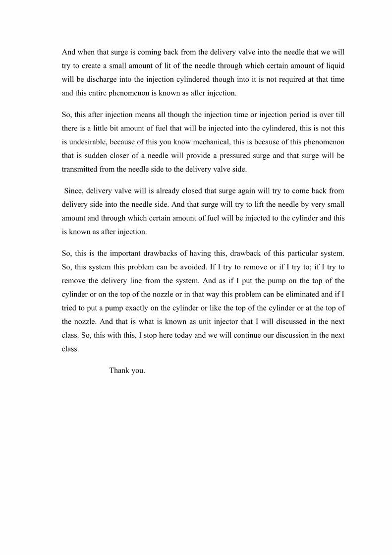
And when that surge is coming back from the delivery valve into the needle that we will
try to create a small amount of lit of the needle through which certain amount of liquid
will be discharge into the injection cylindered though into it is not required at that time
and this entire phenomenon is known as after injection.
So, this after injection means all though the injection time or injection period is over till
there is a little bit amount of fuel that will be injected into the cylindered, this is not this
is undesirable, because of this you know mechanical, this is because of this phenomenon
that is sudden closer of a needle will provide a pressured surge and that surge will be
transmitted from the needle side to the delivery valve side.
Since, delivery valve will is already closed that surge again will try to come back from
delivery side into the needle side. And that surge will try to lift the needle by very small
amount and through which certain amount of fuel will be injected to the cylinder and this
is known as after injection.
So, this is the important drawbacks of having this, drawback of this particular system.
So, this system this problem can be avoided. If I try to remove or if I try to; if I try to
remove the delivery line from the system. And as if I put the pump on the top of the
cylinder or on the top of the nozzle or in that way this problem can be eliminated and if I
tried to put a pump exactly on the cylinder or like the top of the cylinder or at the top of
the nozzle. And that is what is known as unit injector that I will discussed in the next
class. So, this with this, I stop here today and we will continue our discussion in the next
class.
Thank you.