Embed Size (px)
Citation preview

IC Compiler™ IIData ModelUser Guide
Version L-2016.03-SP4, September 2016

Copyright Notice and Proprietary Information©2016 Synopsys, Inc. All rights reserved. This Synopsys software and all associated documentation are proprietary to Synopsys, Inc. and may only be used pursuant to the terms and conditions of a written license agreement with Synopsys, Inc. All other use, reproduction, modification, or distribution of the Synopsys software or the associated documentation is strictly prohibited.
Destination Control StatementAll technical data contained in this publication is subject to the export control laws of the United States of America. Disclosure to nationals of other countries contrary to United States law is prohibited. It is the reader's responsibility to determine the applicable regulations and to comply with them.
DisclaimerSYNOPSYS, INC., AND ITS LICENSORS MAKE NO WARRANTY OF ANY KIND, EXPRESS OR IMPLIED, WITH REGARD TO THIS MATERIAL, INCLUDING, BUT NOT LIMITED TO, THE IMPLIED WARRANTIES OF MERCHANTABILITY AND FITNESS FOR A PARTICULAR PURPOSE.
TrademarksSynopsys and certain Synopsys product names are trademarks of Synopsys, as set forth athttp://www.synopsys.com/Company/Pages/Trademarks.aspx.All other product or company names may be trademarks of their respective owners.
Third-Party LinksAny links to third-party websites included in this document are for your convenience only. Synopsys does not endorse and is not responsible for such websites and their practices, including privacy practices, availability, and content.
Synopsys, Inc.690 E. Middlefield RoadMountain View, CA 94043www.synopsys.com
IC Compiler™ II Data Model User Guide, Version L-2016.03-SP4 ii

Copyright Notice for the Command-Line Editing Feature© 1992, 1993 The Regents of the University of California. All rights reserved. This code is derived from software contributed to Berkeley by Christos Zoulas of Cornell University.
Redistribution and use in source and binary forms, with or without modification, are permitted provided that the following conditions are met:1.Redistributions of source code must retain the above copyright notice, this list of conditions and the following
disclaimer.2.Redistributions in binary form must reproduce the above copyright notice, this list of conditions and the following
disclaimer in the documentation and/or other materials provided with the distribution.3.All advertising materials mentioning features or use of this software must display the following acknowledgement:
This product includes software developed by the University of California, Berkeley and its contributors.
4.Neither the name of the University nor the names of its contributors may be used to endorse or promote products derived from this software without specific prior written permission.
THIS SOFTWARE IS PROVIDED BY THE REGENTS AND CONTRIBUTORS "AS IS" AND ANY EXPRESS OR IMPLIED WARRANTIES, INCLUDING, BUT NOT LIMITED TO, THE IMPLIED WARRANTIES OF MERCHANTABILITY AND FITNESS FOR A PARTICULAR PURPOSE ARE DISCLAIMED. IN NO EVENT SHALL THE REGENTS OR CONTRIBUTORS BE LIABLE FOR ANY DIRECT, INDIRECT, INCIDENTAL, SPECIAL, EXEMPLARY, OR CONSEQUENTIAL DAMAGES (INCLUDING, BUT NOT LIMITED TO, PROCUREMENT OF SUBSTITUTE GOODS OR SERVICES; LOSS OF USE, DATA, OR PROFITS; OR BUSINESS INTERRUPTION) HOWEVER CAUSED AND ON ANY THEORY OF LIABILITY, WHETHER IN CONTRACT, STRICT LIABILITY, OR TORT (INCLUDING NEGLIGENCE OR OTHERWISE) ARISING IN ANY WAY OUT OF THE USE OF THIS SOFTWARE, EVEN IF ADVISED OF THE POSSIBILITY OF SUCH DAMAGE.
Copyright Notice for the Line-Editing Library© 1992 Simmule Turner and Rich Salz. All rights reserved.
This software is not subject to any license of the American Telephone and Telegraph Company or of the Regents of the University of California.
Permission is granted to anyone to use this software for any purpose on any computer system, and to alter it and redistribute it freely, subject to the following restrictions: 1.The authors are not responsible for the consequences of use of this software, no matter how awful, even if they arise
from flaws in it. 2.The origin of this software must not be misrepresented, either by explicit claim or by omission. Since few users ever
read sources, credits must appear in the documentation. 3.Altered versions must be plainly marked as such, and must not be misrepresented as being the original software.
Since few users ever read sources, credits must appear in the documentation. 4.This notice may not be removed or altered.
IC Compiler™ II Data Model User Guide, Version L-2016.03-SP4 iii

IC Compiler™ II Data Model User Guide, Version L-2016.03-SP4 iv

Contents
About This User Guide . . . . . . . . . . . . . . . . . . . . . . . . . . . . . . . . . . . . . . . . . . . . . . . x
Customer Support. . . . . . . . . . . . . . . . . . . . . . . . . . . . . . . . . . . . . . . . . . . . . . . . . . . xii
1. Libraries and Blocks
Design Libraries . . . . . . . . . . . . . . . . . . . . . . . . . . . . . . . . . . . . . . . . . . . . . . . . . . . . 1-2
Relative and Absolute Paths to Design Libraries. . . . . . . . . . . . . . . . . . . . . . . . 1-5
Creating a Design Library . . . . . . . . . . . . . . . . . . . . . . . . . . . . . . . . . . . . . . . . . 1-5
Opening a Design Library . . . . . . . . . . . . . . . . . . . . . . . . . . . . . . . . . . . . . . . . . 1-6
Setting the Current Design Library . . . . . . . . . . . . . . . . . . . . . . . . . . . . . . . . . . 1-7
Querying a Design Library . . . . . . . . . . . . . . . . . . . . . . . . . . . . . . . . . . . . . . . . . 1-7
Saving a Design Library. . . . . . . . . . . . . . . . . . . . . . . . . . . . . . . . . . . . . . . . . . . 1-10
Closing a Design Library . . . . . . . . . . . . . . . . . . . . . . . . . . . . . . . . . . . . . . . . . . 1-10
Design Library Open Count . . . . . . . . . . . . . . . . . . . . . . . . . . . . . . . . . . . . . . . . 1-11
Reference Libraries . . . . . . . . . . . . . . . . . . . . . . . . . . . . . . . . . . . . . . . . . . . . . . . . . 1-13
Reference Library List. . . . . . . . . . . . . . . . . . . . . . . . . . . . . . . . . . . . . . . . . . . . . . . . 1-14
Specifying a Design Library’s Reference Libraries . . . . . . . . . . . . . . . . . . . . . . 1-16Relative and Absolute Paths to Reference Libraries . . . . . . . . . . . . . . . . . 1-17Reporting Reference Libraries . . . . . . . . . . . . . . . . . . . . . . . . . . . . . . . . . . 1-18Rebinding Reference Libraries of a Design Library . . . . . . . . . . . . . . . . . . 1-18
Reading a Hierarchical Design Into a Single Design Library . . . . . . . . . . . . . . . 1-19
Reading a Hierarchical Design Into Multiple Design Libraries. . . . . . . . . . . . . . 1-20
Technology Data . . . . . . . . . . . . . . . . . . . . . . . . . . . . . . . . . . . . . . . . . . . . . . . . . . . . 1-21
Specifying a Library’s Technology File. . . . . . . . . . . . . . . . . . . . . . . . . . . . . . . . 1-23
Technology File Compatibility . . . . . . . . . . . . . . . . . . . . . . . . . . . . . . . . . . . . . . 1-24
v

IC Compiler™ II Data Model User Guide L-2016.03-SP4IC Compiler™ II Data Model User Guide Version L-2016.03-SP4
Specifying a Design Library’s Technology Library . . . . . . . . . . . . . . . . . . . . . . . 1-25
Blocks . . . . . . . . . . . . . . . . . . . . . . . . . . . . . . . . . . . . . . . . . . . . . . . . . . . . . . . . . . . . 1-25
Block Naming Conventions . . . . . . . . . . . . . . . . . . . . . . . . . . . . . . . . . . . . . . . . 1-28Block Labels . . . . . . . . . . . . . . . . . . . . . . . . . . . . . . . . . . . . . . . . . . . . . . . . 1-30Block Views . . . . . . . . . . . . . . . . . . . . . . . . . . . . . . . . . . . . . . . . . . . . . . . . 1-33
Creating a Block . . . . . . . . . . . . . . . . . . . . . . . . . . . . . . . . . . . . . . . . . . . . . . . . 1-35
Opening a Block . . . . . . . . . . . . . . . . . . . . . . . . . . . . . . . . . . . . . . . . . . . . . . . . 1-36
Setting the Current Block. . . . . . . . . . . . . . . . . . . . . . . . . . . . . . . . . . . . . . . . . . 1-36
Querying Blocks. . . . . . . . . . . . . . . . . . . . . . . . . . . . . . . . . . . . . . . . . . . . . . . . . 1-37
Saving a Block . . . . . . . . . . . . . . . . . . . . . . . . . . . . . . . . . . . . . . . . . . . . . . . . . . 1-38
Closing a Block . . . . . . . . . . . . . . . . . . . . . . . . . . . . . . . . . . . . . . . . . . . . . . . . . 1-39
Block Open Count . . . . . . . . . . . . . . . . . . . . . . . . . . . . . . . . . . . . . . . . . . . . . . . 1-40
Block Types . . . . . . . . . . . . . . . . . . . . . . . . . . . . . . . . . . . . . . . . . . . . . . . . . . . . . . . 1-41
Designs . . . . . . . . . . . . . . . . . . . . . . . . . . . . . . . . . . . . . . . . . . . . . . . . . . . . . . . 1-42
Library Cells. . . . . . . . . . . . . . . . . . . . . . . . . . . . . . . . . . . . . . . . . . . . . . . . . . . . 1-43
Sparse Libraries . . . . . . . . . . . . . . . . . . . . . . . . . . . . . . . . . . . . . . . . . . . . . . . . . . . . 1-44
Creating a Sparse Library . . . . . . . . . . . . . . . . . . . . . . . . . . . . . . . . . . . . . . . . . 1-46
Remote and Local Blocks . . . . . . . . . . . . . . . . . . . . . . . . . . . . . . . . . . . . . . . . . 1-47
Reverting Blocks in a Sparse Library. . . . . . . . . . . . . . . . . . . . . . . . . . . . . . . . . 1-48
Synchronizing a Sparse Library to a Base Library. . . . . . . . . . . . . . . . . . . . . . . 1-49
Synchronizing a Base Library to a Sparse Library. . . . . . . . . . . . . . . . . . . . . . . 1-50
File Attachments . . . . . . . . . . . . . . . . . . . . . . . . . . . . . . . . . . . . . . . . . . . . . . . . . . . . 1-51
Library Packaging . . . . . . . . . . . . . . . . . . . . . . . . . . . . . . . . . . . . . . . . . . . . . . . . . . . 1-51
Creating a Library Package . . . . . . . . . . . . . . . . . . . . . . . . . . . . . . . . . . . . . . . . 1-52
Restoring Data From a Library Package . . . . . . . . . . . . . . . . . . . . . . . . . . . . . . 1-53
2. Data Import and Export
Reading a Verilog Netlist . . . . . . . . . . . . . . . . . . . . . . . . . . . . . . . . . . . . . . . . . . . . . 2-2
Allowing Inconsistent Design Data . . . . . . . . . . . . . . . . . . . . . . . . . . . . . . . . . . . . . . 2-3
Creating a Custom Mismatch Configuration . . . . . . . . . . . . . . . . . . . . . . . . . . . 2-5
Setting a Mismatch Configuration . . . . . . . . . . . . . . . . . . . . . . . . . . . . . . . . . . . 2-5
Reporting Mismatch Configurations. . . . . . . . . . . . . . . . . . . . . . . . . . . . . . . . . . 2-6
Saving a Design in ASCII Format . . . . . . . . . . . . . . . . . . . . . . . . . . . . . . . . . . . . . . . 2-6
Writing a Design in GDSII or OASIS Stream Format . . . . . . . . . . . . . . . . . . . . . . . . 2-7
Contents vi

IC Compiler™ II Data Model User Guide Version L-2016.03-SP4
Reading and Writing LEF Data . . . . . . . . . . . . . . . . . . . . . . . . . . . . . . . . . . . . . . . . . 2-8
IC Compiler II Layer Mapping File . . . . . . . . . . . . . . . . . . . . . . . . . . . . . . . . . . . . . . 2-9
IC Compiler II Layer Mapping Syntax . . . . . . . . . . . . . . . . . . . . . . . . . . . . . . . . 2-10
Layer Mapping File Statements . . . . . . . . . . . . . . . . . . . . . . . . . . . . . . . . . . . . . 2-11
Guidelines for Writing and Reading GDSII and OASIS . . . . . . . . . . . . . . . . . . . 2-12
IC Compiler Layer Mapping File Syntax . . . . . . . . . . . . . . . . . . . . . . . . . . . . . . . . . . 2-14
Changing Object Names. . . . . . . . . . . . . . . . . . . . . . . . . . . . . . . . . . . . . . . . . . . . . . 2-18
Changing Object Names Using Custom Rules . . . . . . . . . . . . . . . . . . . . . . . . . 2-18
Changing Object Names for Verilog Output. . . . . . . . . . . . . . . . . . . . . . . . . . . . 2-21
3. Working With Design Data
Application Options. . . . . . . . . . . . . . . . . . . . . . . . . . . . . . . . . . . . . . . . . . . . . . . . . . 3-2
Setting Application Options . . . . . . . . . . . . . . . . . . . . . . . . . . . . . . . . . . . . . . . . 3-4
Querying Application Options . . . . . . . . . . . . . . . . . . . . . . . . . . . . . . . . . . . . . . 3-4
Help on Application Options . . . . . . . . . . . . . . . . . . . . . . . . . . . . . . . . . . . . . . . 3-6
Man Pages for Application Options . . . . . . . . . . . . . . . . . . . . . . . . . . . . . . . . . . 3-7
User Default for Application Options . . . . . . . . . . . . . . . . . . . . . . . . . . . . . . . . . 3-8
Resetting Application Options . . . . . . . . . . . . . . . . . . . . . . . . . . . . . . . . . . . . . . 3-9
Objects and Collections . . . . . . . . . . . . . . . . . . . . . . . . . . . . . . . . . . . . . . . . . . . . . . 3-9
Common Design Objects. . . . . . . . . . . . . . . . . . . . . . . . . . . . . . . . . . . . . . . . . . 3-11
Object Attributes . . . . . . . . . . . . . . . . . . . . . . . . . . . . . . . . . . . . . . . . . . . . . . . . 3-13
Querying Objects . . . . . . . . . . . . . . . . . . . . . . . . . . . . . . . . . . . . . . . . . . . . . . . . 3-16Query by Location. . . . . . . . . . . . . . . . . . . . . . . . . . . . . . . . . . . . . . . . . . . . 3-17Query by Association . . . . . . . . . . . . . . . . . . . . . . . . . . . . . . . . . . . . . . . . . 3-19Query in Physical Context . . . . . . . . . . . . . . . . . . . . . . . . . . . . . . . . . . . . . 3-19Cascaded Attributes . . . . . . . . . . . . . . . . . . . . . . . . . . . . . . . . . . . . . . . . . . 3-20
Removing Objects . . . . . . . . . . . . . . . . . . . . . . . . . . . . . . . . . . . . . . . . . . . . . . . 3-21
Bus and Name Expansion . . . . . . . . . . . . . . . . . . . . . . . . . . . . . . . . . . . . . . . . . . . . 3-22
Design Hierarchy . . . . . . . . . . . . . . . . . . . . . . . . . . . . . . . . . . . . . . . . . . . . . . . . . . . 3-23
current_block . . . . . . . . . . . . . . . . . . . . . . . . . . . . . . . . . . . . . . . . . . . . . . . . . . . 3-25
current_design . . . . . . . . . . . . . . . . . . . . . . . . . . . . . . . . . . . . . . . . . . . . . . . . . . 3-25
current_instance . . . . . . . . . . . . . . . . . . . . . . . . . . . . . . . . . . . . . . . . . . . . . . . . 3-26
report_hierarchy. . . . . . . . . . . . . . . . . . . . . . . . . . . . . . . . . . . . . . . . . . . . . . . . . 3-26
Hierarchical Query Using get_* Commands . . . . . . . . . . . . . . . . . . . . . . . . . . . 3-27Query Using Only a Search String . . . . . . . . . . . . . . . . . . . . . . . . . . . . . . . 3-28
Chapter 1: Contents1-viiContents vii

IC Compiler™ II Data Model User Guide L-2016.03-SP4IC Compiler™ II Data Model User Guide Version L-2016.03-SP4
Query With the -hierarchical Option . . . . . . . . . . . . . . . . . . . . . . . . . . . . . . 3-29Query With the -physical_context Option . . . . . . . . . . . . . . . . . . . . . . . . . . 3-29Query With the -of_objects Option . . . . . . . . . . . . . . . . . . . . . . . . . . . . . . . 3-30Query With the -filter Option . . . . . . . . . . . . . . . . . . . . . . . . . . . . . . . . . . . . 3-30
Technology Data Access. . . . . . . . . . . . . . . . . . . . . . . . . . . . . . . . . . . . . . . . . . . . . . 3-31
Reporting Design Information . . . . . . . . . . . . . . . . . . . . . . . . . . . . . . . . . . . . . . . . . . 3-34
Reporting Design Information With the report_design Command . . . . . . . . . . . 3-34
Reporting Physical Constraints With the
check_physical_constraints Command . . . . . . . . . . . . . . . . . . . . . . . . . . . . . . . 3-36
Polygon Manipulation . . . . . . . . . . . . . . . . . . . . . . . . . . . . . . . . . . . . . . . . . . . . . . . . 3-37
Creating poly_rect and geo_mask Objects . . . . . . . . . . . . . . . . . . . . . . . . . . . . 3-39
Converting geo_mask Objects Into Functional Shapes. . . . . . . . . . . . . . . . . . . 3-41
Undoing and Redoing Changes to the Design . . . . . . . . . . . . . . . . . . . . . . . . . . . . . 3-42
Undoing or Redoing Multiple Changes . . . . . . . . . . . . . . . . . . . . . . . . . . . . . . . 3-44
Disabling or Limiting the Undo Feature . . . . . . . . . . . . . . . . . . . . . . . . . . . . . . . 3-45
Schema Versions . . . . . . . . . . . . . . . . . . . . . . . . . . . . . . . . . . . . . . . . . . . . . . . . . . . 3-46
Contents viii

Preface
This preface includes the following sections:
• About This User Guide
• Customer Support
ix

IC Compiler™ II Data Model User Guide L-2016.03-SP4IC Compiler™ II Data Model User Guide Version L-2016.03-SP4
About This User Guide
The Synopsys IC Compiler II tool provides a complete netlist-to-GDSII design solution, which combines proprietary design planning, physical synthesis, clock tree synthesis, and routing for logical and physical design implementations throughout the design flow.
This guide describes the creation, access, editing, and storage of design data using the IC Compiler II implementation and library manager tools. For more information about these tools, see the following companion volumes:
• IC Compiler II Library Preparation User Guide
• IC Compiler II Design Planning User Guide
• IC Compiler II Implementation User Guide
• IC Compiler II Timing Analysis User Guide
• IC Compiler II Graphical User Interface User Guide
Audience
This user guide is for design engineers who use the IC Compiler II library manager and implementation tools to prepare libraries and implement designs.
To use the IC Compiler II tool, you need to be skilled in physical design and synthesis, and be familiar with the following:
• Physical design principles
• The Linux or UNIX operating system
• The tool command language (Tcl)
Related Publications
For additional information about the IC Compiler II tool, see the documentation on the Synopsys SolvNet® online support site at the following address:
https://solvnet.synopsys.com/DocsOnWeb
You might also want to see the documentation for the following related Synopsys products:
• Design Compiler®
• IC Validator
• PrimeTime® Suite
PrefaceAbout This User Guide x
IC Compiler™ II Data Model User Guide Version L-2016.03-SP4
Release Notes
Information about new features, enhancements, changes, known limitations, and resolved Synopsys Technical Action Requests (STARs) is available in the IC Compiler II Release Notes on the SolvNet site.
To see the IC Compiler II Release Notes,
1. Go to the SolvNet Download Center located at the following address:
https://solvnet.synopsys.com/DownloadCenter
2. Select IC Compiler II, and then select a release in the list that appears.
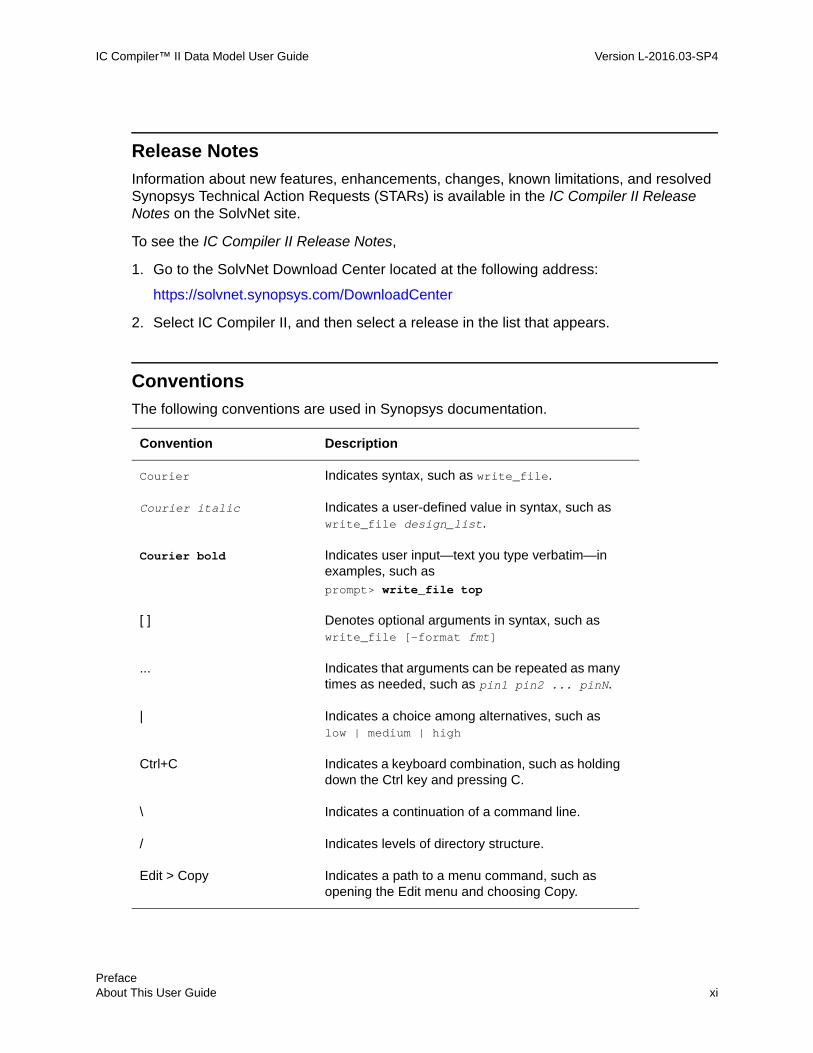
Conventions
The following conventions are used in Synopsys documentation.
Convention Description
Courier Indicates syntax, such as write_file.
Courier italic Indicates a user-defined value in syntax, such as write_file design_list.
Courier bold Indicates user input—text you type verbatim—in examples, such asprompt> write_file top
[ ] Denotes optional arguments in syntax, such as write_file [-format fmt]
... Indicates that arguments can be repeated as many times as needed, such as pin1 pin2 ... pinN.
| Indicates a choice among alternatives, such as low | medium | high
Ctrl+C Indicates a keyboard combination, such as holding down the Ctrl key and pressing C.
\ Indicates a continuation of a command line.
/ Indicates levels of directory structure.
Edit > Copy Indicates a path to a menu command, such as opening the Edit menu and choosing Copy.
Chapter 1: PrefaceAbout This User Guide 1-xiPrefaceAbout This User Guide xi

IC Compiler™ II Data Model User Guide L-2016.03-SP4IC Compiler™ II Data Model User Guide Version L-2016.03-SP4
Customer Support
Customer support is available through SolvNet online customer support and through contacting the Synopsys Technical Support Center.
Accessing SolvNet
The SolvNet site includes a knowledge base of technical articles and answers to frequently asked questions about Synopsys tools. The SolvNet site also gives you access to a wide range of Synopsys online services including software downloads, documentation, and technical support.
To access the SolvNet site, go to the following address:
https://solvnet.synopsys.com
If prompted, enter your user name and password. If you do not have a Synopsys user name and password, follow the instructions to sign up for an account.
If you need help using the SolvNet site, click HELP in the top-right menu bar.
Contacting the Synopsys Technical Support Center
If you have problems, questions, or suggestions, you can contact the Synopsys Technical Support Center in the following ways:
• Open a support case to your local support center online by signing in to the SolvNet site at https://solvnet.synopsys.com, clicking Support, and then clicking “Open A Support Case.”
• Send an e-mail message to your local support center.
❍ E-mail [email protected] from within North America.
❍ Find other local support center e-mail addresses at
http://www.synopsys.com/Support/GlobalSupportCenters/Pages
• Telephone your local support center.
❍ Call (800) 245-8005 from within North America.
❍ Find other local support center telephone numbers at
http://www.synopsys.com/Support/GlobalSupportCenters/Pages
PrefaceCustomer Support xii

1Libraries and Blocks 1
A block is a container for physical and functional design data. A library is a collection of related blocks, together with technology information that applies to the block collection. A chip design consists of one or more blocks, often stored in different design libraries. A design library uses instances of blocks defined in lower-level libraries, called reference libraries. A design library can serve as a reference library for another design library.
The following topics describe the usage of libraries and blocks:
• Design Libraries
• Reference Libraries
• Reference Library List
• Technology Data
• Blocks
• Block Types
• Sparse Libraries
• File Attachments
• Library Packaging
1-1

IC Compiler™ II Data Model User Guide L-2016.03-SP4IC Compiler™ II Data Model User Guide Version L-2016.03-SP4
Design Libraries
A design library is a collection of related blocks, together with additional information that applies to the block collection. When you open a library in the implementation tool (icc2_shell) or library manager tool (icc2_lm_shell), you can view and edit the library contents and add or remove blocks.
All of the information about a design is stored in a design library and its associated reference libraries. In addition to the technology data and reference library list, a library contains various views of each block stored in the library, as shown in the following figure.
Figure 1-1 Design Library Contents
In this document, the terms library and design library are both used to describe IC Compiler II design database libraries. A library can contain one or more different designs, or a complete hierarchical design that includes all views of the design. You can store the parts of a design in a single library or in multiple libraries that share the same technology information. A library containing only leaf-level blocks is called a reference library.
The current library is the default library affected by library-related commands. The last library opened is the current library by default. You can also explicitly set the current library by using the current_lib command.
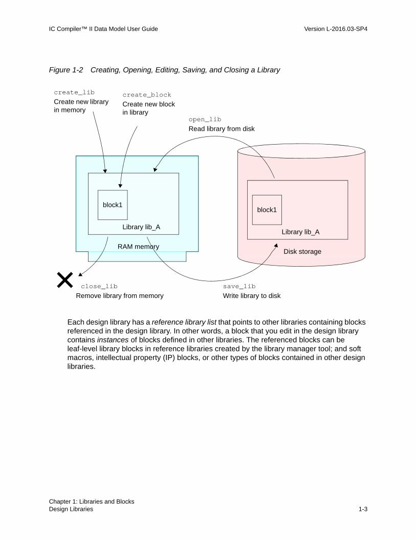
The create_lib command creates a new design library and optionally specifies the associated technology data and reference libraries. You create blocks in a library by using the create_block command. The save_lib command saves an open library to disk and the open_lib command opens a saved library for block access, as shown in the following figure.
my_des_libraryblock_top
design viewTechnology data
Reference library list
block_A
design view
frame view
abstract view
block_B
design view
abstract view
Chapter 1: Libraries and BlocksDesign Libraries 1-2
IC Compiler™ II Data Model User Guide Version L-2016.03-SP4
Figure 1-2 Creating, Opening, Editing, Saving, and Closing a Library
Each design library has a reference library list that points to other libraries containing blocks referenced in the design library. In other words, a block that you edit in the design library contains instances of blocks defined in other libraries. The referenced blocks can be leaf-level library blocks in reference libraries created by the library manager tool; and soft macros, intellectual property (IP) blocks, or other types of blocks contained in other design libraries.
create_lib
Library lib_A
Remove library from memory
open_lib
save_lib
block1
Library lib_A
block1
close_lib
Write library to disk
Read library from disk
Create new library in memory
Disk storageRAM memory
create_block
Create new block in library
Chapter 1: Libraries and BlocksDesign Libraries 1-3Chapter 1: Libraries and BlocksDesign Libraries 1-3

IC Compiler™ II Data Model User Guide L-2016.03-SP4IC Compiler™ II Data Model User Guide Version L-2016.03-SP4
The following table briefly describes the commands that operate on libraries.
For more information about working with design libraries, see
• Relative and Absolute Paths to Design Libraries
• Creating a Design Library
• Opening a Design Library
• Setting the Current Design Library
• Querying a Design Library
• Saving a Design Library
• Closing a Design Library
• Design Library Open Count
Table 1-1 Commands That Operate on Design Libraries
Command Description
close_lib Closes a library, removing it from memory
copy_lib Copies a library on disk
create_lib Creates a library in memory
current_lib Sets or gets the current library
move_lib Moves a library on disk
open_lib Opens a saved library for viewing or editing
report_lib Reports library information
save_lib Saves a library to disk
get_libs Creates a collection of the libraries loaded in memory
report_ref_libs Reports the reference libraries of a library loaded in memory
set_ref_libs Sets the reference libraries for a library loaded in memory
Chapter 1: Libraries and BlocksDesign Libraries 1-4

IC Compiler™ II Data Model User Guide Version L-2016.03-SP4
See Also
• Reference Library List
• Technology Data
• Blocks
• Library Packaging
Relative and Absolute Paths to Design Libraries
When you create, open, query, save, or close a design library, you can specify an absolute path, a relative path, or no path at all with the library name, as in the following examples.
icc2_shell> open_lib lib_A # No path, opens lib in search_path...icc2_shell> open_lib ./lib_A # Relative path, current directory...icc2_shell> open_lib ../lib_A # Relative path, parent of current dir...icc2_shell> open_lib ../../mylibs/lib_A # Relative up 2 levels, down 1...icc2_shell> open_lib /remote/home/mylibs/lib_A # Absolute path to lib...
This is how the tool finds the specified library:
• No path – The tool looks in the directories specified by the search_path variable, in the order that the directories are listed in the variable.
• Relative path – The tool looks in the specified directory relative to the current working directory (.) or its parent directory (..).
• Absolute path – The tool looks in the specified absolute path, starting with the slash character (/).
See Also
• Relative and Absolute Paths to Reference Libraries
• Library Packaging
Creating a Design Library
To create a design library, use the create_lib command:
icc2_shell> create_lib my_libA{my_libA}
Chapter 1: Libraries and BlocksDesign Libraries 1-5Chapter 1: Libraries and BlocksDesign Libraries 1-5

IC Compiler™ II Data Model User Guide L-2016.03-SP4IC Compiler™ II Data Model User Guide Version L-2016.03-SP4
This command creates the library in memory and sets it as the current library. A library name can have an extension such as “.ndm” or no extension at all. Slash (/) and colon (:) characters are not allowed in library names.
To save the library to disk, use the save_lib command, or save a block contained in the library using the save_block command.
By default, the library is saved in the first directory specified in the search_path variable. You can specify a relative or absolute path for storing the library:
icc2_shell> create_lib ../my_lib_dir/my_libA{my_libA}
You can specify the associated reference libraries and technology data either when you create the library or sometime later.
Note: To create a reference library (a library containing only leaf-level blocks), use the library manager tool and start with the create_workspace command. For details, see the IC Compiler II Library Preparation User Guide.
See Also
• Relative and Absolute Paths to Design Libraries
• Opening a Design Library
• Saving a Design Library
• Reference Library List
• Technology Data
Opening a Design Library
To open an existing library saved on disk, use the open_lib command:
icc2_shell> open_lib my_libAInformation: Loading library file '/usr/lib/StdCells.ndm' (FILE-007)Information: Loading library file '/usr/lib/RAMs.ndm' (FILE-007)Information: Loading library file '/usr/lib/PhysicalOnly.ndm' (FILE-007){my_libA}
The tool opens the specified library, makes that library the current library, and opens all of its associated reference libraries. Opening a library means loading it into memory and making its blocks accessible.
By default, the open_lib command opens the design library in read/write mode and the associated reference libraries in read-only mode. You can override the default read/write modes by using the -read and -ref_libs_for_edit options with the open_lib command.
Chapter 1: Libraries and BlocksDesign Libraries 1-6

IC Compiler™ II Data Model User Guide Version L-2016.03-SP4
See Also
• Relative and Absolute Paths to Design Libraries
• Creating a Design Library
• Saving a Design Library
• Closing a Design Library
Setting the Current Design Library
The current library is the default library affected by library-related commands. By default, the library most recently opened is the current library. You can explicitly set any open library to be the current library by using the current_lib command:
icc2_shell> current_lib my_libA{my_libA}
To determine which library is the current library, use the current_lib command by itself:
icc2_shell> current_lib{my_libA}
See Also
• Creating a Design Library
• Opening a Design Library
• Querying a Design Library
• Saving a Design Library
• Closing a Design Library
Querying a Design Library
You can get the following types of information about the open libraries:
• The current library – use the current_lib command.
icc2_shell> current_lib{my_design}
• The libraries loaded in memory – use the get_libs command.
icc2_shell> open_lib lib_AInformation: Loading library file '... libA' ...Information: Loading library file '... ref_lib1' ...
Chapter 1: Libraries and BlocksDesign Libraries 1-7Chapter 1: Libraries and BlocksDesign Libraries 1-7

IC Compiler™ II Data Model User Guide L-2016.03-SP4IC Compiler™ II Data Model User Guide Version L-2016.03-SP4
Information: Loading library file '... stdhvt.ndm' ...{lib_A}
icc2_shell> open_lib lib_BInformation: Loading library file '... libB' ...Information: Loading library file '... ref_lib2' ...Information: Loading library file '... stdhvt.ndm' ...{lib_B}
icc2_shell> get_libs # Get all open libs{lib_A lib_B ref_lib1 ref_lib2 stdhvt.ndm}
icc2_shell> get_libs -explicit # Get the libs opened explicitly{lib_A lib_B}
icc2_shell> get_libs -implicit # Get the libs opened as ref libs{ref_lib1 ref_lib2 stdhvt.ndm}
• The blocks in a library – use the get_blocks or list_blocks command.
icc2_shell> get_blocks -all{lib_A:block1.design lib_A:block2.design lib_B:blocka.design lib_B:blockb.design}
icc2_shell> list_blocksLib lib_A /path/libs/lib_A tech current -> 0 block1.design Apr-20-16:36 +> 0 block2.design Apr-20-16:38 currentLib lib_B /path/libs/lib_B tech -> 0 blocka.design Apr-18-14:02 -> 0 blockb.design Apr-18-14:20
icc2_shell> list_blocks lib_BLib lib_B /path/libs/lib_B tech -> 0 blocka.design Apr-18-14:02 -> 0 blockb.design Apr-18-14:20
The characters at the beginning of each row of the block list indicate the following:
+ block open - block not open > block selected to resolve link references * block modified and not yet saved
The word tech at the end of the Lib line indicates that the library has technology data, and the word current means it is the current library.
• The associated reference libraries – use the report_ref_libs command.
icc2_shell> current_lib lib_B{lib_B}icc2_shell> report_ref_libs...
Chapter 1: Libraries and BlocksDesign Libraries 1-8

IC Compiler™ II Data Model User Guide Version L-2016.03-SP4
Library: lib_B... Name Path Location---------------------------------------------------*+ ref_lib1 ../../libs /path/libs/ref_lib1*+ ref_lib2 ../../libs /path/libs/ref_lib2*+ stdhvt ../../libs /path/libs/std/stdhvt.ndm
The characters at the beginning of each row of the library list indicate the following:
* library currently open + library has technology data - library name and location not available
• The associated process technology file data – use the get_techs command.
icc2_shell> get_techs{tech28nm1p tech13nm2x}icc2_shell> get_techs -of_objects lib_A{tech28nm1p}
• The parasitic technology (defined by a TLUPlus file) associated with a library – use the report_lib command.
icc2_shell> report_lib -parasitic_tech my_tech_lib...Library: my_tech_lib...Full name: /path/tech-info/.../my_tech_lib:my_techFile name: /path/tech-info/.../my_tech_libDesign count: 0No timing data
Parasitic tech data:----------------------------------------- Parasitic tech name: my_tech_Cmax Parasitic itf technology name: my_tech_Cmax Parasitic tech type: TLUPLUS Parasitic source file name: /path/Tlup/... ...
See Also
• Relative and Absolute Paths to Design Libraries
• Opening a Design Library
• Setting the Current Design Library
• Saving a Design Library
• Closing a Design Library
Chapter 1: Libraries and BlocksDesign Libraries 1-9Chapter 1: Libraries and BlocksDesign Libraries 1-9

IC Compiler™ II Data Model User Guide L-2016.03-SP4IC Compiler™ II Data Model User Guide Version L-2016.03-SP4
Saving a Design Library
When you create a library or edit its contents, the changes are stored only in memory. To save a library to disk, use the save_lib command.
icc2_shell> current_lib{lib_A}
icc2_shell> save_libSaving library 'lib_A'1
icc2_shell> save_lib lib_BSaving library 'lib_B'1
icc2_shell> save_lib -allSaving all libraries...5
The save_lib command saves all blocks in the library that have been modified and not yet saved. Be sure to save a new or edited library before you close it.
See Also
• Relative and Absolute Paths to Design Libraries
• Creating a Design Library
• Opening a Design Library
• Setting the Current Design Library
• Closing a Design Library
Closing a Design Library
When you no longer need access to data in a library, you can close it. Be sure to save the changes in the library before you close it.
To close a library, use the close_lib command.
icc2_shell> current_lib{lib_A}
icc2_shell> close_libClosing library 'lib_A'1
Chapter 1: Libraries and BlocksDesign Libraries 1-10

IC Compiler™ II Data Model User Guide Version L-2016.03-SP4
icc2_shell> close_lib lib_BClosing library 'lib_B'1
icc2_shell> close_lib -allClosing all libraries...1
To deliberately close an edited library and discard the changes:
icc2_shell> close_lib -forceClosing library 'lib_A'1
Important: By default, when you close a design library by using the close_lib command, the tool does not save the open blocks and does not issue a warning about unsaved design changes. To save new versions for all open blocks in a library, use the -save_designs option with the close_lib command.
If the library open count is 1 or more after you execute the close_lib command, the library remains open.
To remove an unwanted library from disk, first use the remove_blocks command to remove all the blocks in the library. Note that removed blocks cannot be recovered. Then use operating system commands to remove the unwanted library directory.
See Also
• Relative and Absolute Paths to Design Libraries
• Creating a Design Library
• Opening a Design Library
• Setting the Current Design Library
• Saving a Design Library
• Design Library Open Count
Design Library Open Count
The open count of a design library is an integer specifying the number of times the library has been opened. The tool monitors the open count to keep the library open as long as you need access to it, based on a matching number of open_lib and close_lib commands used on the library.
Chapter 1: Libraries and BlocksDesign Libraries 1-11Chapter 1: Libraries and BlocksDesign Libraries 1-11

IC Compiler™ II Data Model User Guide L-2016.03-SP4IC Compiler™ II Data Model User Guide Version L-2016.03-SP4
When you open a closed library or create a new library, its open count is set to 1. Each time the same library is reopened, its open count is incremented by 1:
icc2_shell> open_lib lib_CInformation: Loading library file ...{lib_C}...icc2_shell> open_lib lib_CInformation: Incrementing open_count of library 'lib_C' to 2. (LIB-017)...icc2_shell> open_lib lib_CInformation: Incrementing open_count of library 'lib_C' to 3. (LIB-017)...
Opening a design library also opens its associated reference libraries, which increments the open count for each reference library as well.
The close_lib command decrements a library’s open count by 1. If the resulting new count is 1 or more, the library remains open; or if the new count is 0, the library is closed and removed from memory.
icc2_shell> close_lib lib_CInformation: Decrementing open_count of library 'lib_C' to 2. (LIB-018)1...icc2_shell> close_lib lib_CInformation: Decrementing open_count of library 'lib_C' to 1. (LIB-018)1...icc2_shell> close_lib lib_CClosing library 'lib_C'1
To determine the open count of a library without affecting the count:
icc2_shell> get_attribute [get_libs lib_C] open_count3
To close a library irrespective of its open count:
icc2_shell> close_lib lib_C -purgeClosing library 'lib_C'1
Using the save_lib command does not affect the open count.
Be sure to save a new or edited library before you close it. The tool does not warn you about unsaved data before it closes the library.
See Also
• Creating a Design Library
Chapter 1: Libraries and BlocksDesign Libraries 1-12

IC Compiler™ II Data Model User Guide Version L-2016.03-SP4
• Opening a Design Library
• Saving a Design Library
• Closing a Design Library
Reference Libraries
A library containing only leaf-level blocks is called a reference library or lib_cell library. This type of library is used only as a reference library for design libraries; it does not itself have design-specific data, a reference library list, or lower-level libraries. Reference libraries contain basic leaf-level blocks such as standard logic cells and I/O pads.
Reference libraries are typically provided by a library development group associated with a semiconductor foundry. To create or edit a reference library, use the IC Compiler II Library Manager tool (icc2_lm_shell).
When you open a design library, the tool implicitly opens the related libraries in the reference library list. To open a reference library directly, specify the library file name with the .ndm extension. For all other commands that operate on the reference library, specify the library name without the .ndm extension:
icc2_shell> open_lib /path/nlibs/std32hvt.ndmInformation: Loading library file '/path/nlibs/std32hvt.ndm' (FILE-007){std32hvt}...icc2_shell> get_libs{lib_A lib_B std32hvt}...icc2_shell> current_lib std32hvt{std32hvt}icc2_shell> close_lib std32hvtClosing library 'std32hvt'1
Reference libraries differ from design libraries as described in the following table.
Table 1-2 Differences Between Design Libraries and Reference Libraries
Feature Design library Reference library
Contents Designs, tech data, reference lib list Leaf-level cells
Creation tool Implementation tool (icc2_shell) Library manager tool (icc2_lm_shell)
Disk storage A disk directory, libName[.extension] A single binary file, libName.ndm
Chapter 1: Libraries and BlocksReference Libraries 1-13Chapter 1: Libraries and BlocksReference Libraries 1-13

IC Compiler™ II Data Model User Guide L-2016.03-SP4IC Compiler™ II Data Model User Guide Version L-2016.03-SP4
For information about creating or editing reference libraries, see the IC Compiler II Library Preparation User Guide.
See Also
• Reference Library List
• Specifying a Design Library’s Reference Libraries
• Library Packaging
Reference Library List
You can build a design using instances of blocks defined in the same design library or in other libraries. When you use blocks in other libraries, those other libraries must be in the design library’s reference library list.
You can specify a design library’s reference library list when you create the design library by using the -ref_libs option with the create_lib command. You can also change the reference library list at any time by using the set_ref_libs command. To report the reference library list, use the report_ref_libs command.
The entries in a reference library list each describe a one-way, one-level relationship between two libraries in a design hierarchy. If you set lib_B as a reference library of lib_A, you can use blocks in lib_B as instances in lib_A, but not the other way around.
You can set lib_B to be a reference library of lib_A, and set lib_C to be a reference library of lib_B, as shown in the following figure.
Name extension
Any extension (.ndm, .des, .xyz, ...) or no extension
Always has “.ndm” file name extension
Extension usage
Always refer to library using full name, including extension (if any)
Refer to library name without .ndm extension (except in open_lib command)
Usage as reference lib
Optionally serves as a reference library for higher-level design libraries
Serves only as a reference library for design libraries
Table 1-2 Differences Between Design Libraries and Reference Libraries (Continued)
Feature Design library Reference library
Chapter 1: Libraries and BlocksReference Library List 1-14

IC Compiler™ II Data Model User Guide Version L-2016.03-SP4
Figure 1-3 Reference Library Lists
In that case, you can use blocks from lib_C as instances in lib_B, and use blocks in lib_B as instances in lib_A. However, you cannot directly use blocks in lib_C as instances in lib_A unless you also define a reference library relationship directly between lib_A and lib_C, as shown in the following figure.
Figure 1-4 Reference Library List Spanning Multiple Levels
For more information, see
• Specifying a Design Library’s Reference Libraries
• Relative and Absolute Paths to Reference Libraries
• Reporting Reference Libraries
• Rebinding Reference Libraries of a Design Library
See Also
• Design Libraries
• Blocks
• Library Packaging
Librarylib_A
Blocks defined in lib_C can be used as instances in lib_B
Blocks defined in lib_B can be used as instances in lib_A
Ref. lib list
Librarylib_B
Ref. lib list
Librarylib_C
Ref. lib list
Reference library stdhvt.ndm
Blocks in stdhvt can be used in all the other libs
Librarylib_A
Ref. lib list
Librarylib_B
Ref. lib list
Librarylib_C
Ref. lib list
Reference library stdhvt.ndm
Blocks defined in lib_B, lib_C, and stdhvt can be used as instances in lib_A
Chapter 1: Libraries and BlocksReference Library List 1-15Chapter 1: Libraries and BlocksReference Library List 1-15

IC Compiler™ II Data Model User Guide L-2016.03-SP4IC Compiler™ II Data Model User Guide Version L-2016.03-SP4
Specifying a Design Library’s Reference Libraries
You can specify a relationship between a new design library and its lower-level reference libraries by using the -ref_libs option of the create_lib command:
icc2_shell> create_lib lib_B \ -ref_libs {../LIBS/lib_C ../STND/stdhvt.ndm} ...{lib_B}
For an existing library, open the library and use the set_ref_libs command:
icc2_shell> open_lib lib_BInformation: Loading library file '/remote/home/mylibs/lib_B'{lib_B}icc2_shell> set_ref_libs -ref_libs {../LIBS/lib_C ../STND/stdhvt.ndm}../LIBS/lib_C ../STND/stdhvt.ndm
You can specify the reference libraries using relative paths, absolute paths, or no paths. For details, see Relative and Absolute Paths to Reference Libraries.
The set_ref_libs command has options to add to, replace, and remove existing reference libraries previously defined for the design library; and to rebind the reference libraries when the reference library list no longer correctly points to the reference libraries. You can also control the search order of entries in the reference library list.
If you change the reference libraries associated with a design library, you can update the references of an existing block in the library by using the rebind_block command. To control the order in which different lower-level block views are selected for rebinding, use the set_view_switch_list command.
To report the reference libraries that have been set for a design library, use the report_ref_libs command.
See Also
• Relative and Absolute Paths to Design Libraries
• Design Libraries
• Reference Library List
• Technology Data
Chapter 1: Libraries and BlocksReference Library List 1-16

IC Compiler™ II Data Model User Guide Version L-2016.03-SP4
Relative and Absolute Paths to Reference Libraries
When you set a reference library for a design library using the set_ref_libs or create_lib command, you can specify a simple name with no path, a relative path, or an absolute path to the reference library, as shown in the following examples.
icc2_shell> set_ref_libs -ref_libs stdB.ndm # Uses search_path
icc2_shell> set_ref_libs -ref_libs mylibs/stdB.ndm # Uses search_path
icc2_shell> set_ref_libs -ref_libs ./lib_A # Relative to design lib dir.
icc2_shell> set_ref_libs -ref_libs ../lib_A # Relative up 1 level
icc2_shell> set_ref_libs -ref_libs ../../mylibs/lib_A
icc2_shell> set_ref_libs -ref_libs /remote/home/mylibs/lib_A # Absolute
This is how the tool finds the specified reference library:
• Relative path (recommended) – The tool looks in the specified directory relative to the design library’s directory (.) or the design library’s parent directory (..) . This relative path is stored in the library, so if you move the library and its reference libraries together to a new location, the tool still automatically finds each reference library located in the same place relative to the design library.
• Simple name – The tool looks in the directories specified by the search_path variable, in the order that the directories are listed in the variable.
• Absolute path – The tool looks in the specified absolute path, starting with the slash character (/). This absolute path is stored in the library, so you can move the design library while keeping its reference libraries in the same absolute locations.
If you specify a simple name for the reference library, the command resolves the path by using the search_path variable. This path resolution binds the reference library to the design library. If you want to change the bindings based on a new search_path variable setting, run the set_ref_libs command with the -rebind option. For details, see Rebinding Reference Libraries of a Design Library.
Note: Moving a design library and its reference libraries using the Library Packaging feature (write_lib_package and read_lib_package) moves the reference libraries to a new directory under the restored design library directory and automatically rebinds them. For details, see Restoring Data From a Library Package.
To report the reference libraries of a design library, use the report_ref_libs command. For details, see Reporting Reference Libraries.
Chapter 1: Libraries and BlocksReference Library List 1-17Chapter 1: Libraries and BlocksReference Library List 1-17

IC Compiler™ II Data Model User Guide L-2016.03-SP4IC Compiler™ II Data Model User Guide Version L-2016.03-SP4
See Also
• Specifying a Design Library’s Reference Libraries
• Reference Library List
Reporting Reference Libraries
To report the reference libraries of a design library, use the report_ref_libs command:
icc2_shell> create_lib lib_A -ref_libs \ {../libs/SCLL.ndm ../libs/SCHH.ndm ../BLOCKS/MACROS}{lib_A}icc2_shell> report_ref_libs... Name Path Location ------------------------------------------------------------------*+ SCLL ../libs/SCLL.ndm /remote/project10/test1/libs/SCLL.ndm*+ SCHH ../libs/SCHH.ndm /remote/project10/test1/libs/SCHH.ndm* MACROS ../BLOCKS/MACROS /remote/project10/test1/BLOCKS/MACROS "*" = Library currently open "+" = Library has technology information
The report shows the Name, Path (as originally specified), and Location (absolute path) of each reference library in the design library’s reference library list.
The entry in the Path column is the simple name, relative path, or absolute path originally specified for the reference library.
See Also
• Specifying a Design Library’s Reference Libraries
• Reference Library List
Rebinding Reference Libraries of a Design Library
A design library’s associated reference libraries contain lower-level blocks used as instances in the design library’s blocks. You associate or bind a reference library with a design library by using -ref_libs option of the create_lib command or by using the set_ref_libs command. If you specify a simple name for the reference library, the command resolves the path by using the search_path variable.
Chapter 1: Libraries and BlocksReference Library List 1-18

IC Compiler™ II Data Model User Guide Version L-2016.03-SP4
If you make a change that invalidates the reference library list, you need to rebind the reference libraries. If necessary, first set the search_path variable appropriately, then use the set_ref_libs -rebind command:
icc2_shell> current_lib{lib_A}
icc2_shell> set_app_var search_path {. ../REFLIBS ../NLIBS}. ../REFLIBS ../NLIBS
icc2_shell> set_ref_libs -rebind../REFLIBS/lib_C ../REFLIBS/lib_D ../NLIBS/stdhvt.ndm}
Rebinding a library does not affect the bindings of blocks already existing in the design library. To rebind these blocks using an updated reference library list, use the link_block command with the -rebind option.
See Also
• Specifying a Design Library’s Reference Libraries
• Relative and Absolute Paths to Reference Libraries
• Reporting Reference Libraries
• Reference Library List
Reading a Hierarchical Design Into a Single Design Library
The following script reads a hierarchical design into a single design library (see Figure 1-5). The input netlists are in Verilog format and the input layout information is in DEF format.
create_lib mydesign.ndm -ref_libs {std_cell_lib.ndm} \ –technology mytech.tf read_verilog bot.v # Implicitly creates new block "bot"read_def bot.def... read_verilog mid.v # Implicitly creates new block "mid"read_def mid.def... read_verilog top.v # Implicitly creates new block "top"read_def top.def... save_lib
Chapter 1: Libraries and BlocksReference Library List 1-19Chapter 1: Libraries and BlocksReference Library List 1-19

IC Compiler™ II Data Model User Guide L-2016.03-SP4IC Compiler™ II Data Model User Guide Version L-2016.03-SP4
Figure 1-5 Hierarchical Data Stored in a Single Design Library
See Also
• Design Libraries
• Reference Library List
• Specifying a Design Library’s Reference Libraries
Reading a Hierarchical Design Into Multiple Design Libraries
The following script reads a hierarchical design into different libraries for different levels of the design (see Figure 1-6). The input netlists are in Verilog format and the input layout information is in DEF format.
# Create library bot.ndm and read the designcreate_lib bot.ndm –ref_libs {std_cell_lib.ndm} \ –technology mytech.tf read_verilog bot.v # Implicitly creates new block "bot"read_def bot.def...save_lib # Create library mid.ndm and read the designcreate_lib mid.ndm –ref_libs {std_cell_lib.ndm bot.ndm} \ –technology mytech.tf read_verilog mid.v # Implicitly creates new block "mid"read_def mid.def...save_lib # Create library top.ndm and read the design create_lib top.ndm –ref_libs {std_cell_lib.ndm bot.ndm mid.ndm} \ –technology mytech.tf read_verilog top.v # Implicitly creates new block "top"read_def top.def...save_lib
Library mydesign.ndm
Block “bot”Block “mid”Block “top”
Tech. data
Reference library list
Chapter 1: Libraries and BlocksReference Library List 1-20

IC Compiler™ II Data Model User Guide Version L-2016.03-SP4
Figure 1-6 Hierarchical Design Data Stored in a Multiple Libraries
See Also
• Design Libraries
• Reference Library List
• Specifying a Design Library’s Reference Libraries
Technology Data
Each design library needs process technology information such as measurement units, layers, unit tile dimensions, and routing rules. This type of information comes from a technology file. The tool reads the data from the technology file and stores that information in a library. The technology file syntax is described in the Synopsys Technology File and Routing Rules Reference Manual.
A design library can get its technology information either directly from a technology file or indirectly through another library called a technology library. A technology library contains only technology data and does not have design data or leaf-level reference library cells. The direct method is the preferred method.
The two methods are summarized in the following figures.
Library top.ndm
Block “top”
Tech. data
Reference library list
Library mid.ndm
Block “mid”
Tech. data
Reference library list
Library bot.ndm
Block “bot”
Tech. data
Reference library list
Chapter 1: Libraries and BlocksTechnology Data 1-21Chapter 1: Libraries and BlocksTechnology Data 1-21

IC Compiler™ II Data Model User Guide L-2016.03-SP4IC Compiler™ II Data Model User Guide Version L-2016.03-SP4
Figure 1-7 Direct Method of Specifying a Library’s Technology Data
Figure 1-8 Indirect Method of Specifying a Library’s Technology Data
The IC Compiler II tool requires the site symmetry and each layer’s routing direction and track offset to be defined in the design library or technology library. For details, see “Completing the Technology Information” in the IC Compiler II Library Preparation User Guide.
To report the source of the technology data associated with a library, use the report_ref_libs command.
Design library lib_A gets technology data directly from technology file
create_lib lib_A -technology techA2.tf ...
techA2.tf
Design librarylib_A
Tech
Design library lib_A uses technology data stored in technology library lib_T
create_lib lib_A -use_technology_lib lib_T ...
create_lib lib_T -technology techA2.tf
techA2.tf
Design librarylib_A
Technology librarylib_T
Technology library lib_T gets technology data from file
Tech
create_workspace lib_T -technology techA2.tf ...
or
Chapter 1: Libraries and BlocksTechnology Data 1-22

IC Compiler™ II Data Model User Guide Version L-2016.03-SP4
For more information, see
• Specifying a Library’s Technology File
• Specifying a Design Library’s Technology Library
See Also
• Reference Library List
• Specifying a Design Library’s Reference Libraries
Specifying a Library’s Technology File
To specify the technology file for a new design library, use the -technology option of the create_lib command:
icc2_shell> create_lib my_lib -technology /usr/TECH/my-tech.tfInformation: Loading technology file '/usr/TECH/my-tech.tf' (FILE-007){my_lib}
To update the technology file for an existing library, use the read_tech_file command:
icc2_shell> open_lib my_lib{my_lib}icc2_shell> read_tech_file /usr/TECH/my-tech2.tf Information: Replacing technology file '/usr/TECH/my-tech.tf' with '/usr/TECH/my-tech2.tf' (LIB-037)1
In either case, the command reads the technology file and stores the technology data in the library. After that, the library no longer needs or uses the technology file. However, be sure to keep the technology file for reference and for future updates.
You can specify the technology file using an absolute path, relative path, or a plain name. If you use a plain name, the tool looks for the technology file in the paths defined by the search_path variable.
When you use the read_tech_file command, the data in the new technology file replaces any existing technology data. The new technology data must be upwardly compatible with the existing technology data with respect to layer, contact, and unit tile definitions, as explained in Technology File Compatibility.
Chapter 1: Libraries and BlocksTechnology Data 1-23Chapter 1: Libraries and BlocksTechnology Data 1-23

IC Compiler™ II Data Model User Guide L-2016.03-SP4IC Compiler™ II Data Model User Guide Version L-2016.03-SP4
See Also
• Specifying a Design Library’s Technology Library
• Technology Data
• Technology File Compatibility
• Reference Library List
Technology File Compatibility
When you update the technology file for a library using the read_tech_file command, the data in the new technology file replaces any existing technology data. The new technology data must be upwardly compatible with the existing technology data with respect to unit tile, layer, and contact definitions:
• Unit tiles – The new technology file must contain at least the same Tile definitions, with the same dimensions, as the old technology file.
The new technology can define additional tiles.
• Layers – The new technology file must contain at least the same layers as the old technology file, in the same order, with the same settings for the layer name and the layerNumber, maskName, and dataTypeNumber attribute settings.
The new technology can define additional layers, and the design rules for the existing layers need not be the same as in the old technology.
• Contact codes – The new technology file must contain at least the same ContactCode definitions as the old technology file, with the same settings for the contact name and the cutLayer, lowerLayer, and upperLayer attribute settings.
The new technology can define additional contact codes, and the design rules for the existing contact codes need not be the same as in the old technology.
Be sure that the new technology file is compatible. The read_tech_file command applies the newly specified technology file without checking for compatibility.
See Also
• Technology Data
• Specifying a Library’s Technology File
Chapter 1: Libraries and BlocksTechnology Data 1-24

IC Compiler™ II Data Model User Guide Version L-2016.03-SP4
Specifying a Design Library’s Technology Library
To specify the technology library for a new design library, use the -ref_libs and -use_technology_lib options of the create_lib command:
icc2_shell> create_lib my_lib -ref_libs {lib_T ref_A} \ -use_technology_lib lib_T ...
To update the technology file associated with an existing design library, use the set_ref_libs command:
icc2_shell> open_lib my_lib{my_lib}icc2_shell> set_ref_libs -ref_libs lib_T2 -use_technology_lib lib_T2lib_T2
The technology library specified with the -use_technology_lib option must be a library containing technology data previously read into it from a technology file, and it must be a library in the -ref_libs list.
See Also
• Specifying a Library’s Technology File
• Technology Data
• Reference Library List
Blocks
A block is a container for physical and functional design data. A typical project consists of the following steps to create and edit each block, at each hierarchical level:
1. Read the design netlist using the read_verilog command. This implicitly creates a new block, like using the create_block command.
2. Read other design information and constraints by using commands such as load_upf, read_sdc, and read_def.
3. Perform physical implementation by using the place_opt, clock_opt, and route_opt commands.
4. Save the block by using the save_block command.
You create, query, and edit blocks in memory. To save a new or edited block to disk, use the save_block command; or to read a block from disk into memory, use the open_block command, as shown in the following figure.
Chapter 1: Libraries and BlocksBlocks 1-25Chapter 1: Libraries and BlocksBlocks 1-25

IC Compiler™ II Data Model User Guide L-2016.03-SP4IC Compiler™ II Data Model User Guide Version L-2016.03-SP4
Figure 1-9 Creating, Opening, Editing, Saving, and Closing a Block
A block can have multiple views, each view containing an alternative representation of the same design:
• Design view – a complete physical view that contains the full design information of the cell
• Frame view – a limited physical view that contains only the information needed to perform placement and routing
• Abstract view – an interface-only block representation used in complex hierarchical designs
• Outline view – a simplified representation used for floorplanning
create_block
Library lib_A
Remove block from memory
read_verilog
open_block
place_optclock_optroute_opt
save_block
blockA blockB blockC
Library lib_A
blockA blockB
close_blocks
Write block to disk
Read block from disk
Create new block in memory
Modify block
current_block
Set pointer to default block for editing
Disk storageRAM memory
Chapter 1: Libraries and BlocksBlocks 1-26

IC Compiler™ II Data Model User Guide Version L-2016.03-SP4
The following table briefly describes the commands that operate on blocks.
For more information about blocks, see:
• Block Naming Conventions
• Block Labels
• Block Views
• Creating a Block
• Opening a Block
• Setting the Current Block
• Querying Blocks
• Saving a Block
Table 1-3 Commands That Operate on Blocks
Command Description
close_blocks Closes a block, removing it from memory
copy_block Copies a block to a new block in the same or different library
create_block Creates a new block in memory
current_block Sets or gets the current block
get_blocks Creates a collection of the blocks loaded in memory
link_block Resolves the references in a block
list_blocks Lists the blocks (stored on disk) in the specified libraries
move_block Moves a block to a new block, library, or view
open_block Opens a saved block for viewing or editing
rebind_block Rebinds the references in a block
remove_blocks Removes a block from memory and disk
reopen_block Changes the open mode (read-only or edit) of an opened block
save_block Saves a block to disk
Chapter 1: Libraries and BlocksBlocks 1-27Chapter 1: Libraries and BlocksBlocks 1-27

IC Compiler™ II Data Model User Guide L-2016.03-SP4IC Compiler™ II Data Model User Guide Version L-2016.03-SP4
• Closing a Block
• Block Open Count
• Block Types
See Also
• Design Libraries
• Reference Library List
• Reference Libraries
• Library Cells
• Library Packaging
Block Naming Conventions
You specify a block using the following format:
[libName:][blockName][/labelName][.viewName]
where blockName is required when you use the create_block and open_block commands.
For example,
icc2_shell> open_block my_lib:MUX2/ver1.design
The following default naming conventions apply to a specified block:
• Default library: current library
• Default block: current block
• Default label: none
• Default view
❍ For the open_block and create_block commands, the default view is the design view.
❍ For the copy_block, move_block, remove_blocks, rename_block, and save_block commands,
■ If you do not specify the source block, the command performs the task on the view of the current block.
Chapter 1: Libraries and BlocksBlocks 1-28
IC Compiler™ II Data Model User Guide Version L-2016.03-SP4
■ If you specify the source block without a view, the command performs the task on all available views of the source block.
For example, if the current block is the design view of the my_lib:MUX2 block, the following commands save only the design view of the block:
save_blocksave_block MUX2.designsave_block my_lib:MUX2.design
The following examples show commands you can use to save all views of the block:
save_block MUX2save_block my_lib:MUX2save_block MUX2 -as NEW_MUX2
The current block is the default block affected by block-related commands. The last block opened is the current block by default. You can explicitly set the current block by using the current_block command.
You can create and access a block in the current library using a simple name:
create_block MUX2save_block MUX2close_blocks MUX2open_block MUX2
If you want to use a more complex block name, append a label using a slash character:
icc2_shell> create_block MUX3/ver1
Block labels are useful for maintaining different block versions in hierarchical designs.
Note that you cannot use a period character to add a block name extension:
icc2_shell> create_block MUX3.ver1Error: Invalid block name 'MUX3.ver1'. (DES-008)...
The period character is reserved for designating the view name: .design, .frame, .abstract, or .outline.
For more information about block naming conventions, see
• Block Labels
• Block Views
Chapter 1: Libraries and BlocksBlocks 1-29Chapter 1: Libraries and BlocksBlocks 1-29

IC Compiler™ II Data Model User Guide L-2016.03-SP4IC Compiler™ II Data Model User Guide Version L-2016.03-SP4
Block Labels
When you create a block, you can optionally specify a label as part of the block name. You can use labels to make different versions of the same block. Each version is considered a separate block. For a hierarchical design, you can effectively manage different versions of the full hierarchy by using different labels for different design versions.
If used, the label follows a slash character:
[libName:][blockName][/labelName][.viewName]
For example, to specify “ver1” as a block label:
icc2_shell> open_block my_lib:MUX2/ver1.design
The default label is an empty string. In other words, there is no default label. You can use labels only for designs in design libraries, not library cells in reference libraries.
To save a block on disk using a new or different label, use the save_block command with the -label option. You can save different versions of a block while maintaining the current block setting in the tool:
current_block blkZsave_block -label v1save_block -label v2current_block
See Also
• Block Views
• Block Naming Conventions
Using Labels in a Hierarchical Design
Suppose that you have a top-level design named chip/floor in a design library named lib_A. The block contains instances U1 and U2, which represent lower-level blocks named cpu/floor and alu/floor in reference library lib_B, as shown in the following figure. All of the blocks are at the floorplanned stage.
Chapter 1: Libraries and BlocksBlocks 1-30

IC Compiler™ II Data Model User Guide Version L-2016.03-SP4
Figure 1-10 Hierarchical Design Using Block Names With Labels
You decide to proceed to the placement stage, and you want to keep a copy of the design at the floorplanned stage for possible modification later. You save the chip/floor block to a new block named chip/placed by using the save_block -hierarchical command:
icc2_shell> current_block icc2_shell> save_block -hierarchical -label placed
or equivalently:
icc2_shell> save_block -hierarchical -as chip/placed ...
This effectively copies the chip/floor block to a new block, including its full hierarchy, creating new blocks in both the current library and the lower-level reference library. Then you can edit the new top-level and new lower-level blocks, leaving the original blocks unchanged, as shown in the following figure.
lib_A Ref. lib list
lib_B
cpu/floor block
alu/floor block
chip/floor block
U1
U2
Chapter 1: Libraries and BlocksBlocks 1-31Chapter 1: Libraries and BlocksBlocks 1-31

IC Compiler™ II Data Model User Guide L-2016.03-SP4IC Compiler™ II Data Model User Guide Version L-2016.03-SP4
Figure 1-11 Copying a Hierarchical Design With Labels
See Also
• Block Labels
Creating a Label When Reading a Verilog Netlist
When you read a Verilog netlist with the read_verilog command, the command creates a new block to contain the netlist. If you want the new block to have a label, you can do either of the following:
• Specify the label name together with the design name:
icc2_shell> read_verilog mychip.v -design chip/floor...
• Set the file.verilog.default_user_label application option to the desired label name before you read in the Verilog netlist:
icc2_shell> set_app_options \ -name file.verilog.default_user_label -value floorfile.verilog.default_user_label flooricc2_shell> read_verilog mychip.v -design chipInformation: Reading Verilog into new design 'chip/floor' in lib ......
U1
U2
lib_A Ref. lib list
lib_B
cpu/floor block
alu/floor block
chip/floor block
U1
U2
cpu/placed block
alu/placed block
chip/placed block
Whole design hierarchy copied using new label
save_block \ -hierarchical \ -label placed
Chapter 1: Libraries and BlocksBlocks 1-32

IC Compiler™ II Data Model User Guide Version L-2016.03-SP4
See Also
• Block Labels
• Block Naming Conventions
Block Views
A block can have multiple views, with each view containing an alternative representation of the block used for a specific purpose. The IC Compiler II infrastructure supports the following types of views for blocks in design libraries:
• Design view (.design) – a complete physical view that contains the full design information of the cell, including placed block instances and routed nets. This is the default view type.
• Frame view (.frame) – a limited physical view that contains only the information needed to perform placement of the block as an instance and routing to the ports of the instance: the block outline, pins, via regions, and routing blockages.
• Abstract view (.abstract) – a simplified view that contains only the interface information of a subdesign, used for placement and timing analysis at the next higher level of the design. For details, see the IC Compiler II Implementation User Guide.
• Outline view (.outline) – a simplified view of a large child block that contains only the hierarchy information, without nets or leaf-level library cells, used for floorplan creation. For details, see the IC Compiler II Design Planning User Guide.
The following figure shows how the block views are stored in a typical design library.
Figure 1-12 Design Library Contents
my_des_libraryblock_top
design viewTechnology data
Reference library list
block_A
design view
frame view
abstract view
block_B
design view
frame view
Chapter 1: Libraries and BlocksBlocks 1-33Chapter 1: Libraries and BlocksBlocks 1-33

IC Compiler™ II Data Model User Guide L-2016.03-SP4IC Compiler™ II Data Model User Guide Version L-2016.03-SP4
The following additional types of views are supported for library-cell blocks in reference libraries:
• Timing view (.timing) – a functional description of the timing, logic, and power characteristics of a library cell. The implementation tool uses this information for timing analysis, power analysis, and optimization.
• Layout view (.layout) – a physical-only view of the shapes in a library cell, which contains the same information as the GDSII description of the cell, not including connectivity and pin information. The library manager tool uses this view as a data source for generating the design view for a library cell, and the implementation tool uses this view for mask generation.
Note: The layout view (.layout) applies only to leaf-level library cells. This is different from the “layout view” shown in GUI windows when you view a design. The GUI “layout view” shows the full chip layout, which is actually a display of the design view of the block.
When you create, open, save, or close a block, you specify the block view as the last item in the full block name, after the period character:
[libName:][blockName][/labelName][.viewName]
For example, the following command opens the frame view of block NAND2/ver1:
icc2_shell> open_block NAND2/ver1.frame
If you do not specify a view name,
• The create_block and open_block commands open the design view of the block.
• The copy_block, move_block, remove_blocks, rename_block, and save_block commands operate on all available views of the block.
The implementation tool resolves the hierarchical references of a design when you run the link_block command or when the tool performs linking implicitly. The process of associating a block to its lower-level reference blocks is called binding.
To specify the order in which different views are selected for binding, use the set_view_switch_list command. You can set the view type priority at the block level, at the library level, and globally.
To query the current order of priority, use the get_view_switch_list command. The default order is {abstract design frame outline}.
To rebind an existing block, use either the rebind_block or link_block -rebind command:
icc2_shell> rebind_blockUsing libraries: lib_A lib_B tech32lvtBlock 'block1' was successfully rebound.
Chapter 1: Libraries and BlocksBlocks 1-34

IC Compiler™ II Data Model User Guide Version L-2016.03-SP4
1
icc2_shell> link_block -rebind -forceUsing libraries: lib_A lib_B tech32lvtVisiting block lib_A:block1.designDesign 'block1' was successfully linked.
See Also
• Block Labels
• Block Types
• Library Cells
• Blocks
Creating a Block
To create a new block for holding design data, use the create_block command:
icc2_shell> create_block MUX2Information: Creating block 'MUX2.design' in library 'my_lib'. (DES-013){my_lib:MUX2.design}
This command creates the block in memory and sets it as the current block. To save the new block, use the save_block command.
To create a new block that overwrites an existing block of the same name:
icc2_shell> create_block -force MUX2
The read_verilog command implicitly creates a new block to contain the Verilog netlist read by the command, so there is no need for the create_block command in that situation.
See Also
• Block Naming Conventions
• Opening a Block
• Saving a Block
• Closing a Block
• Reading a Verilog Netlist
• Blocks
Chapter 1: Libraries and BlocksBlocks 1-35Chapter 1: Libraries and BlocksBlocks 1-35

IC Compiler™ II Data Model User Guide L-2016.03-SP4IC Compiler™ II Data Model User Guide Version L-2016.03-SP4
Opening a Block
To open an existing saved block for viewing or editing, use the open_block command:
icc2_shell> open_block my_lib:MUX2Opening block 'my_lib:MUX2.design'{my_lib:MUX2.design}
The tool opens the specified block and sets it as the current block. If you specify the library name with the block name (for example, my_lib:MUX2), the tool also opens that library, if it is not already open, and sets it as the current library.
To open a block in read-only mode:
icc2_shell> open_block -read my_lib:MUX2
See Also
• Block Naming Conventions
• Creating a Block
• Saving a Block
• Closing a Block
• Blocks
Setting the Current Block
The current block is the default block affected by block-related commands. By default, the block most recently opened is the current block. To explicitly set a block to be the current block, use the current_block command:
icc2_shell> current_block MUX2{my_lib:MUX2.design}
The tool sets the specified block as the current block. The block must be already open. If you specify the library name together with the block name (for example, my_lib:MUX2), the tool also sets that library as the current library.
To determine which block is the current block, use the current_block command by itself:
icc2_shell> current_block{my_lib:MUX2.design}
Chapter 1: Libraries and BlocksBlocks 1-36

IC Compiler™ II Data Model User Guide Version L-2016.03-SP4
See Also
• Block Naming Conventions
• Creating a Block
• Opening a Block
• Querying Blocks
• Saving a Block
• Closing a Block
• Blocks
Querying Blocks
You can get the following types of information about the open blocks:
• The current block – use the current_block command.
icc2_shell> current_block{my_lib:MUX2.design}
• The blocks in the library – use the list_blocks command.
icc2_shell> list_blocksLib lib_A /path/lib_dir/lib_A current +> 0 MUX2.design Apr-30-21:01 +> 0 MUX3.design Apr-30-21:29 currentLib lib_B /path/lib_dir/lib_B + 0 ADDR1.design Apr-29-20:543
icc2_shell> list_blocks lib_BLib lib_B /path/lib_dir/lib_B + 0 ADDR1.design Apr-29-20:541
By default, the list_blocks command lists all blocks in all open libraries, but not blocks in associated reference libraries. Use the list_blocks command options to override the default behavior:
icc2_shell> list_blocks libA # List blocks in library lib_A only...icc2_shell> list_blocks -ref_libs # List blocks in ref libs also...icc2_shell> list_blocks -lib_cells # List lib_cell blocks also...
Chapter 1: Libraries and BlocksBlocks 1-37Chapter 1: Libraries and BlocksBlocks 1-37
IC Compiler™ II Data Model User Guide L-2016.03-SP4IC Compiler™ II Data Model User Guide Version L-2016.03-SP4
• Create a block collection – use the get_blocks command.
icc2_shell> set my_blks1 [get_blocks] # Get open blocks in current lib{lib_A:MUX2.design lib_A:MUX3.design}
icc2_shell> set my_blks2 [get_blocks -all] # Get blocks in open libs{lib_A:MUX2.design lib_A:MUX3.design lib_B:ADDR1.design}
icc2_shell> set my_blks2 [get_blocks *ADDR* -all] # Search string{lib_B:ADDR1.design}
See Also
• Block Naming Conventions
• Querying a Design Library
• Opening a Block
• Setting the Current Block
• Saving a Block
• Closing a Block
• Blocks
Saving a Block
By default, a block you create or edit exists only in memory and is lost when you end the tool session. To save a block to disk, use the save_block command:
icc2_shell> save_block MUX2
By default, the command saves only the specified block and ignores any lower-level blocks. To also save the lower-level blocks of the specified block:
icc2_shell> save_block MUX2 -hierarchical
To save a block with a new name without affecting the original saved block or current block setting:
icc2_shell> save_block MUX2 -as MUX2BInformation: Saving 'lib_A:MUX2.design' to 'lib_A:MUX2B.design' ...
To save a block with a new or different label without affecting the original saved block or current block setting:
icc2_shell> save_block MUX2 -label ver1Information: Saving 'lib_A:MUX2.design' to 'lib_A:MUX2/ver1.design' ...
Chapter 1: Libraries and BlocksBlocks 1-38

IC Compiler™ II Data Model User Guide Version L-2016.03-SP4
See Also
• Creating a Block
• Opening a Block
• Closing a Block
• Blocks
Closing a Block
When you no longer need access to a block, you can close it with the close_blocks command:
icc2_shell> close_blocks MUX2Closing block 'lib_A:MUX2.design'1
To automatically save a block before closing it:
icc2_shell> close_blocks -save MUX2...
Alternatively, you can first save the block by using the save_block command.
To close a block and deliberately discard recent changes to the block:
icc2_shell> close_blocks -force MUX2
If the block open count is 1 or more after you execute the close_lib command, the block remains open.
To remove unwanted blocks from disk, use the remove_blocks command. Note that removed blocks cannot be recovered.
Do not attempt to add, move, or delete block files directly using operating system commands, as doing so can corrupt the database.
See Also
• Block Naming Conventions
• Creating a Block
• Opening a Block
• Setting the Current Block
• Saving a Block
Chapter 1: Libraries and BlocksBlocks 1-39Chapter 1: Libraries and BlocksBlocks 1-39
IC Compiler™ II Data Model User Guide L-2016.03-SP4IC Compiler™ II Data Model User Guide Version L-2016.03-SP4
• Block Open Count
• Blocks
Block Open Count
The open count of a block is an integer specifying the number of times the block has been opened. The tool monitors the open count to keep the block open as long as you need access to it, based on the number of open_block and close_blocks commands used on the block. The tool assumes that you want the block to be closed when the number of close_blocks commands equals the number of open_block commands.
When you use the create_block or open_block command, the block’s open count is set to 1. Each time the same block is reopened, its open count is incremented by 1:
icc2_shell> open_block MUX3Opening block 'lib2:MUX3.design'...icc2_shell> open_block MUX3Information: Incrementing open_count of block 'lib2:MUX3.design' to 2...{lib2:MUX3.design}...icc2_shell> open_block MUX3Information: Incrementing open_count of block 'lib2:MUX3.design' to 3...{lib2:MUX3.design}...
Opening a hierarchical block also opens its associated lower-level blocks, which increments the open count for each of the lower-level blocks as well.
The close_blocks command decrements the block’s open count by 1. If the new count is 1 or more, the block remains open; or if the new count is 0, the block is closed and removed from memory.
icc2_shell> close_blocks MUX3Information: Decrementing open_count of block 'lib2:MUX3.design' to 2......icc2_shell> close_blocks MUX3Information: Decrementing open_count of block 'lib2:MUX3.design' to 1......icc2_shell> close_blocks MUX3Closing block 'lib2:MUX3.design'1
To close a block irrespective of the open count:
icc2_shell> close_blocks MUX3 -purgeClosing block 'lib2:MUX3.design'
Chapter 1: Libraries and BlocksBlocks 1-40

IC Compiler™ II Data Model User Guide Version L-2016.03-SP4
To determine the open count of a block without affecting the count, use the get_attribute command:
icc2_shell> get_attribute [get_blocks MUX3] open_count3
Using the save_block command does not affect the open count.
To determine whether a block is already open:
icc2_shell> open_block -check MUX3Opening block 'my_lib:MUX3.design'{my_lib:MUX3.design}
If the block is already open, it stays open without any change to the block’s open count. If the block is not already open, the command returns an error message.
See Also
• Block Naming Conventions
• Creating a Block
• Opening a Block
• Saving a Block
• Closing a Block
• Blocks
Block Types
A block contains both physical layout data and functional design information to support synthesis, analysis, and optimization of the physical design.
With respect to the design hierarchy, there are two basic types of blocks: designs, which are the top-level and intermediate-level blocks, and library cells, which are the leaf-level blocks. Designs are stored in design libraries, whereas library cells are stored in reference libraries.
A block can have multiple views, with each view containing an alternative representation of a design. Each type of view serves a specific purpose.
For more information, see
• Designs
• Library Cells
Chapter 1: Libraries and BlocksBlock Types 1-41Chapter 1: Libraries and BlocksBlock Types 1-41

IC Compiler™ II Data Model User Guide L-2016.03-SP4IC Compiler™ II Data Model User Guide Version L-2016.03-SP4
• Block Labels
• Block Views
See Also
• Design Libraries
• Reference Library List
• Creating a Block
• Opening a Block
• Saving a Block
• Closing a Block
• Blocks
Designs
A design is a representation of a circuit that consists of block instances and connections. A typical way to build a design is to read a Verilog netlist into a new block and have the IC Compiler II tool perform placement and routing based on the netlist contents.
The lower-level blocks used to build a design can be library cells, macros (hierarchical cells that represent lower-level designs), or a combination of both types of cells. A design can itself be used as a macro instance inside another design at a higher level of hierarchy.
See Also
• Design Libraries
• Reference Library List
• Specifying a Design Library’s Reference Libraries
• Block Labels
• Blocks
Chapter 1: Libraries and BlocksBlock Types 1-42
IC Compiler™ II Data Model User Guide Version L-2016.03-SP4
Library Cells
A library cell (lib_cell object) is a representation of a leaf-level function such as logic gate or I/O pad. A library cell model includes physical information such as layer shapes, pins, and routing blockages; and functional information such as logic, timing, and power parameters. Library cells are stored in reference libraries.
The following commands operate on library cells:
• get_lib_cells – Creates a collection of library cells
• report_lib_cells – Generates a report on specified library cells
• set_lib_cell_purpose – Specifies how a collection of library cells can be used, either including or excluding purposes such as clock tree synthesis, optimization, or hold fixing
To list or query library cells and their attributes:
icc2_shell> list_blocks -lib_cells ...icc2_shell> get_blocks -of_objects [get_libs stdhvt] -lib_cells...icc2_shell> list_attributes -application -class lib_cell...icc2_shell> get_attribute -objects [get_lib_cells stdhvt/DFF1] -name area7.8785icc2_shell> report_attributes -application -class lib_cell \ [get_lib_cells stdhvt/DFF1A]...
A library cell model typically consists of different block views used for different purposes:
• design view for storing the physical and functional details
• frame view for placement and routing
• timing view for storing the timing, power, and noise characteristics of the cell
• layout view for library cell preparation and mask generation, containing only the geometric data obtained from a GDSII file
A reference library contains a set of library cells available to be used in a process technology. This type of library is typically provided by a library development group associated with a semiconductor foundry. Because a reference library contains only leaf-level cells, it does not have its own reference library list.
A reference library is stored as a single file on disk named libname.ndm. If you open this type of library using the open_lib command, you specify the library file name with the .ndm extension. In most other commands, you refer to the library by its name without the .ndm extension.
Chapter 1: Libraries and BlocksBlock Types 1-43Chapter 1: Libraries and BlocksBlock Types 1-43

IC Compiler™ II Data Model User Guide L-2016.03-SP4IC Compiler™ II Data Model User Guide Version L-2016.03-SP4
For information about preparing library cells and reference libraries, see the IC Compiler II Library Preparation User Guide.
See Also
• Design Libraries
• Reference Library List
• Reference Libraries
• Block Views
• Blocks
Sparse Libraries
When multiple users or projects share a common set of data, you can use sparse libraries to efficiently share the common data. A single central base library contains the stable data shared between different users or projects, while multiple sparse libraries build upon that data by modifying the blocks in the base library or by adding new blocks.
You create a sparse library by using the create_lib command with the -base_lib option to specify the related base library. The sparse library initially uses the technology data, reference library list, and blocks of the base library. After you create a sparse library, you can modify its contents without affecting the base library.
The following figure shows how the tool maintains the contents of a sparse library.
Chapter 1: Libraries and BlocksSparse Libraries 1-44

IC Compiler™ II Data Model User Guide Version L-2016.03-SP4
Figure 1-13 Base Library and Sparse Library Relationships
When you create a new sparse library, it points to the contents in the related base library, so its contents are exactly the same as the base library. When you edit a block in the sparse library, such as blockC in the figure, that block becomes different from the one in the base library, so that block is saved locally in the sparse library directory.
Multiple users can create multiple sparse libraries associated with the same base library. These users concurrently share the same data in the base library, without any chance of corrupting the shared database. All changes they make to their sparse libraries affect only their own libraries, not the base library.
The base library associated with a sparse library can itself be a sparse library, as shown the following figure. Library s_libA is a sparse library to libA but also a base library to the new sparse library s_s_libA. To find the blocks of the sparse library s_s_libA, the tool traverses the chain of sparse-base libraries until it finds a locally saved block.
Figure 1-14 Sparse Library Used as a Base for Another Sparse Library
libA
blockA blockB blockC
Base library
s_libA
blockA blockB blockC
New sparse library
s_libA
blockA blockBblockC (edited)
Sparse library after editing
Edit blockC
libA
blockA blockB blockC
Base library
These two blocks are different
libA
Base library
s_libA
Sparse library / base library
s_s_libA
New sparse library
blockA blockA blockAblockB blockC blockB blockC blockB blockC
Chapter 1: Libraries and BlocksSparse Libraries 1-45Chapter 1: Libraries and BlocksSparse Libraries 1-45

IC Compiler™ II Data Model User Guide L-2016.03-SP4IC Compiler™ II Data Model User Guide Version L-2016.03-SP4
For more information, see
• Creating a Sparse Library
• Remote and Local Blocks
• Reverting Blocks in a Sparse Library
• Synchronizing a Sparse Library to a Base Library
• Synchronizing a Base Library to a Sparse Library
Creating a Sparse Library
To create a new sparse library, use the create_lib command with the -base_lib option to specify the related base library:
icc2_shell> create_lib -base_lib libA s_libA...Information: Creating Sparse View library 's_libA' with base library 'libA'. (NDM-103)...{s_libA}
The base library can be either open or closed. If closed, it must be accessible in the paths specified by the search_path variable. If you specify a simple name, the command uses the search_path variable to search for the base library and uses the first one that it finds. The base library can itself be a sparse library.
The new sparse library initially contains the same blocks, reference library list, and technology data as its base library. When you add, edit, or remove blocks, the tool stores the changes in the local library directory.
To save a sparse library, use the save_lib command, just like any library:
icc2_shell> save_libSaving library 's_libA'1
To determine whether a library is sparse, query its is_sparse attribute:
icc2_shell> get_attribute -name is_sparse [get_libs libA]falseicc2_shell> get_attribute -name is_sparse [get_libs s_libA]true
To determine a sparse library’s base library, query its base_lib attribute:
icc2_shell> get_attribute -name base_lib [get_libs s_libA]libA
Chapter 1: Libraries and BlocksSparse Libraries 1-46

IC Compiler™ II Data Model User Guide Version L-2016.03-SP4
See Also
• Sparse Libraries
• Remote and Local Blocks
• Synchronizing a Sparse Library to a Base Library
• Synchronizing a Base Library to a Sparse Library
Remote and Local Blocks
You can use commands such as create_block, open_block, save_block, copy_block, and reopen_block to edit the contents of a sparse library, just like any library.
A block saved and maintained in the base library called is a remote block, whereas a block saved and maintained in the sparse library directory is a called a local block. Opening or copying a remote block in a sparse library is an in-memory operation. When you save the block, the block becomes local and is saved in the local sparse library directory. The local block is maintained separately from the remote block.
If you save a hierarchical remote block, that block and its lower-level blocks are all made local and saved in the local sparse library directory.
To determine whether an open block is remote or local, query the block’s is_remote attribute:
icc2_shell> open_block BLK1 # Open remote block stored in base library...icc2_shell> create_block BLK5 # Create local block in sparse library...icc2_shell> get_attribute -name is_remote [get_blocks BLK1]trueicc2_shell> get_attribute -name is_remote [get_blocks BLK5]false...icc2_shell> save_block BLK1 # Saving BLK1 makes it local...icc2_shell> get_attribute -name is_remote [get_blocks BLK1]false
To create a collection of all local blocks in the current library:
icc2_shell> get_blocks -filter "is_remote == false"{BLK1 BLK5}
To create a collection of all open sparse libraries:
icc2_shell> get_libs -filter "is_sparse == true"{s_libA x_libA y_libA]
Chapter 1: Libraries and BlocksSparse Libraries 1-47Chapter 1: Libraries and BlocksSparse Libraries 1-47

IC Compiler™ II Data Model User Guide L-2016.03-SP4IC Compiler™ II Data Model User Guide Version L-2016.03-SP4
Commands that operate on blocks in a sparse library only affect that library; they have no effect on blocks in the base library. For example, if you remove a remote block from a sparse library using the remove_blocks command, that block ceases to exist in the sparse library and can no longer be opened there, even though the same block still exists in the base library.
See Also
• Sparse Libraries
• Creating a Sparse Library
• Reverting Blocks in a Sparse Library
• Synchronizing a Sparse Library to a Base Library
• Synchronizing a Base Library to a Sparse Library
Reverting Blocks in a Sparse Library
To revert a block means to discard the local block saved in a sparse directory and go back to using the identically named block in the base library. To revert one or more blocks, use the revert_blocks command. This command works only when the blocks are closed, as shown in the following example.
icc2_shell> create_lib -base_lib libA s_libA...Information: Creating Sparse View library 's_libA' with base library 'libA'. (NDM-103)...icc2_shell> open_block BLK1Information: Updating library catalog of Sparse View library 's_libA'...Information: Adding block 'BLK1.design' to Sparse View library 's_libA'. (NDM-105)...icc2_shell> save_block BLK1...icc2_shell> get_attribute -name is_remote [get_blocks BLK1]falseicc2_shell> close_blocks BLK1 # Must close block before reverting...icc2_shell> revert_blocks BLK1 ...Information: Reverted design 's_libA:BLK1.design' and removed it ...1icc2_shell> open_block BLK1 # Reopen remote block stored in base library...icc2_shell> get_attribute -name is_remote [get_blocks BLK1]true
Chapter 1: Libraries and BlocksSparse Libraries 1-48

IC Compiler™ II Data Model User Guide Version L-2016.03-SP4
Note that reverting is different from removing a block. Removing a block discards the local block and also makes the original remote block inaccessible.
If you accidentally remove a block when you meant only to revert it, you can recover the block from the base library by rebasing the sparse library with the set_base_lib command, without affecting other local blocks in the sparse library. For details, see Synchronizing a Sparse Library to a Base Library.
See Also
• Sparse Libraries
• Creating a Sparse Library
• Remote and Local Blocks
• Synchronizing a Sparse Library to a Base Library
• Synchronizing a Base Library to a Sparse Library
Synchronizing a Sparse Library to a Base Library
In some situations, you might need to rebase a sparse library, which means to update the association between the sparse library and its base library without affecting the local blocks in the sparse library. For example,
• The base library has been renamed or moved.
• The technology data, reference library list, or blocks in the base library have been changed.
• You removed (instead of reverted) a block from the sparse library, and you need to recover the original block from the base library.
• You want to associate a sparse library with a different base library.
To rebase a sparse library, first close all the open blocks in the library, then use the set_base_lib command to specify the new or modified base library:
icc2_shell> current_lib s_libA # Existing sparse library{s_libA}icc2_shell> close_blocks * # Close all open blocks...icc2_shell> set_base_lib -library s_libA -base_lib libB...Information: Rebasing Sparse View library 's_libA' to base library 'libB'. (NDM-103)...Information: Updating library catalog of Sparse View library 's_libA' from base library 'libB'. (NDM-104)
Chapter 1: Libraries and BlocksSparse Libraries 1-49Chapter 1: Libraries and BlocksSparse Libraries 1-49

IC Compiler™ II Data Model User Guide L-2016.03-SP4IC Compiler™ II Data Model User Guide Version L-2016.03-SP4
... -- marking removal of design: s_libA:BLK1.design missing in base-lib: 'libB' -- marking addition of design: libB:BLKZ.designInformation: Removing block 's_libA:new_block.design' from Sparse View library 's_libA'. (NDM-106)Information: Adding block 'BLKZ.design' to Sparse View library 's_libA'. (NDM-105)
Rebasing a sparse library updates the contents of the library based on the contents of the new or updated base library. Remote blocks no longer existing in the base library are removed from the sparse library, and any new remote blocks are added to the sparse library. Local blocks in the sparse library are not affected, irrespective of the new base library contents.
You can specify the path to the base library as a simple name, a relative path, or an absolute path. If you specify a simple name, the command uses the search_path variable to search for the base library and uses the first one that it finds.
To query the path to the base library from a sparse library, look at the sparse library’s base_lib_path attribute:
icc2_shell> get_attribute -name base_lib_path [get_libs s_libA]/remote/path/user/icc2data/tmp/libA
Setting the base_lib_path attribute using the set_attribute command has the same effect as using the set_base_lib command.
See Also
• Synchronizing a Base Library to a Sparse Library
Synchronizing a Base Library to a Sparse Library
A base library typically contains stable data that can be shared among multiple sparse libraries, and the related sparse libraries contain only blocks that differ from the common base. However, in some situations, you might want to move data from a sparse library to the base library so that the other sparse libraries can have access to that data.
The IC Compiler II tool does not provide commands specifically for updating a base library with data from a sparse library. However, you can manually update the base library with data taken from a sparse library.
For example, suppose you have a base library named libA containing a block BLK1, and a sparse library named s_libA containing a newer version of BLK1. To update the base library
Chapter 1: Libraries and BlocksSparse Libraries 1-50

IC Compiler™ II Data Model User Guide Version L-2016.03-SP4
with the newer version of BLK1, use the following script to copy the newer version back to the base library.
open_lib s_libA # Open sparse libraryopen_lib -edit libA # Open base library for editingcopy_block -from_block s_libA:BLK1 -to_block libA:BLK1 # Copy blocksave_lib libA # Save modified base library
See Also
• Synchronizing a Sparse Library to a Base Library
File Attachments
You can attach any type of file to a block or library. The attached file becomes part of the block or library database. You can use this feature to store any important information related to the block or library such as design specifications, Tcl scripts, or signoff documents.
The following commands support the file attachment feature:
• add_attachment – Attaches a file to a specified block or library; copies the file into the block or library database.
• report_attachments – Reports the attachments on a block or library.
• open_attachment – Opens a file handle for the attachment, like the Tcl open command, allowing you to read or restore the file.
• remove_attachments – Removes one or more attached files from a block or library.
For details, see the man pages for the add_attachment, report_attachments, open_attachment, and remove_attachments commands.
Library Packaging
To transfer or archive a chip design, you can put all of the library data and environment settings into a single file called a library package:
• The write_lib_package command puts the library data and environment settings into a library package file.
• The read_lib_package command restores the original data and environment settings from the library package file.
Chapter 1: Libraries and BlocksFile Attachments 1-51Chapter 1: Libraries and BlocksFile Attachments 1-51

IC Compiler™ II Data Model User Guide L-2016.03-SP4IC Compiler™ II Data Model User Guide Version L-2016.03-SP4
The following figure shows how to create and restore a library package.
Figure 1-15 Creating a Library Package and Restoring the Library Data
For details, see
• Creating a Library Package
• Restoring Data From a Library Package
Creating a Library Package
To create a library package, use the write_lib_package command:
icc2_shell> current_lib # Check current library{my_lib}icc2_shell> write_lib_package desA.pkg # Create package for current lib1
By default, the write_lib_package command creates a library package file that contains the current library, its reference libraries, and environment settings such as Tcl variables, application options, and current block.
Librarymy_lib
Ref. lib list
Libraryref1
Libraryhvt.ndm
Tcl variable settings
Application option settings
Librarymy_lib
Ref. lib list
Libraryref1
Libraryhvt.ndm
Tcl variable settings
Application option settings
write_lib_package desA.pkg
read_lib_package desA.pkg
Library package file
desA.pkg
Chapter 1: Libraries and BlocksLibrary Packaging 1-52

IC Compiler™ II Data Model User Guide Version L-2016.03-SP4
The command writes the library package file to the current working directory. The file name can have any extension such as “.pkg” or no extension at all.
The write_lib_package command has options to
• Create a package for a library other than the current library (-library)
• Include only a specified subset of the library blocks in the package (-blocks)
• Exclude specified reference libraries from the package (-exclude_ref_libs)
• Report the command progress and application options being saved (-verbose)
See Also
• Library Packaging
• Restoring Data From a Library Package
• Design Libraries
• Blocks
Restoring Data From a Library Package
To restore the data stored in a library package, use the read_lib_package command:
icc2_shell> read_lib_package /path/pkgs/desA.pkgInformation: Loading library file '/path/working2/my_lib' (FILE-007)Information: Loading library file '/path/working2/my_lib/reflibs/ref1'Information: Loading library file '/path/working2/my_lib/reflibs/hvt.ndm'Opening block 'my_lib:top.design'1icc2_shell> current_lib{my_lib}icc2_shell> report_ref_libs... Name Path Location --------------------------------------------* ref1 my_lib/reflibs/ref1 /path/working2/my_lib/reflibs/ref1*+ hvt my_lib/reflibs/hvt.ndm /path/working2/my_lib/reflibs/hvt.ndm "*" = Library currently open "+" = Library has technology information1
By default, the read_lib_package command restores the library to the current working directory, unpacks and restores the reference libraries, and invokes the saved environment settings such as Tcl variables, application options, open blocks, and current block.
Chapter 1: Libraries and BlocksLibrary Packaging 1-53Chapter 1: Libraries and BlocksLibrary Packaging 1-53

IC Compiler™ II Data Model User Guide L-2016.03-SP4IC Compiler™ II Data Model User Guide Version L-2016.03-SP4
The read_lib_package command has options to:
• Specify a destination directory for writing the library (-destination)
• Overwrite an existing library in the destination directory (-overwrite)
The unpacking of the libraries in the reference library list does not preserve the original absolute or relative locations of those libraries. Instead, the tool restores all of the reference libraries to a single subdirectory named “reflibs” under the directory where the design library is restored, as shown in the following figure.
Figure 1-16 Original and Restored Reference Library Locations
In the restored design library, the library list correctly points to the new locations of the restored reference libraries. You can begin working on the restored design immediately, without concern for the changed reference library locations.
See Also
• Library Packaging
• Creating a Library Package
• Design Libraries
• Blocks
Library package file
desA.pkg
working mid_ref_libs
project
my_lib
top.design
ref1
blk1.design
hvt.ndm
ref1
working2
path
my_lib
reflibs
hvt.ndm
top.design
write_lib_package desA.pkg read_lib_package desA.pkg
Reference libraries are
restored here
Original directory structure Restored directory structure
blk1.design
. . .
. . .
current_lib
current_lib
Chapter 1: Libraries and BlocksLibrary Packaging 1-54

2Data Import and Export 2
When you work with a design in the IC Compiler II tool, you open and edit the design view of a block stored in a design library.
You can read and save the design data as described in the following topics:
• Reading a Verilog Netlist
• Allowing Inconsistent Design Data
• Saving a Design in ASCII Format
• Writing a Design in GDSII or OASIS Stream Format
• Reading and Writing LEF Data
• IC Compiler II Layer Mapping File
• IC Compiler Layer Mapping File Syntax
• Changing Object Names
2-1

IC Compiler™ II Data Model User Guide L-2016.03-SP4IC Compiler™ II Data Model User Guide Version L-2016.03-SP4
Reading a Verilog Netlist
The starting point for physical implementation is a design netlist in the Verilog hardware description language. The IC Compiler II tool reads one or more structural gate-level Verilog netlists and uses this information as the basis for placement and routing.
To read a Verilog netlist into the implementation tool,
1. Read the Verilog netlist files for the design by using the read_verilog command:
icc2_shell> read_verilog ../my_data/my_des.v
The command implicitly creates a new block named top_module_name.design and reads the Verilog netlist data into the block.
The command identifies the top-level module as the only module in the Verilog file not used as an instance by any other modules. If the file has multiple modules not used as instances, you need to identify the one that is the top-level module:
icc2_shell> read_verilog -top my_top ../my_data/my_des.v
To explicitly specify a new block name other than top_module_name.design:
icc2_shell> read_verilog -top my_top -design desA ../my_data/my_des.v
2. If you are not using a UPF file to specify the power infrastructure, and if you want to explicitly specify the power and ground supply port and net names (the default names are VDD and VSS), specify the names as application options. For example,
set_app_options -name mv.pg.default_power_supply_port_name -value VD1set_app_options -name mv.pg.default_power_supply_net_name -value VD1set_app_options -name mv.pg.default_ground_supply_port_name -value VS1set_app_options -name mv.pg.default_ground_supply_net_name -value VS1
3. Link the block by using the link_block command:
icc2_shell> link_block...Design 'desA' was successfully linked1
The linking process resolves the cell references by searching the reference libraries in the order specified by the library’s reference library list.
To save the block to disk, use the save_block command.
To write out the Verilog netlist for the block, use the write_verilog command.
Chapter 2: Data Import and ExportReading a Verilog Netlist 2-2

IC Compiler™ II Data Model User Guide Version L-2016.03-SP4
See Also
• Creating a Design Library
• Opening a Design Library
• Saving a Block
• Saving a Design in ASCII Format
• Changing Object Names for Verilog Output
Allowing Inconsistent Design Data
During early design development, design data needs to be updated regularly. For example, a block recently updated by a block-level designer might have fewer pins than the same block that was used by a top-level designer. By default, the tool cannot link any block with inconsistent or mismatching data.
To enable the tool to successfully link a block even if it has incomplete or inconsistent data, set a mismatch configuration for the block. In that case, the tool either ignores or fixes several different types of mismatching data, and continues the linking process. Blocks linked with mismatching data can be used only for preroute feasibility analysis.
You set the mismatch configuration by using the set_current_mismatch_config command, as described in Setting a Mismatch Configuration. These are the mismatch configuration types:
• Tapeout (default)
This configuration does not allow any mismatching data.
• Custom
This configuration allows the linker to either ignore or repair each of the mismatch types shown in Table 2-1, as specified by the create_mismatch_config command. For details, see Creating a Custom Mismatch Configuration.”
• Prototype
This configuration allows the linker to repair all the mismatch types shown in Table 2-1.
Chapter 2: Data Import and ExportAllowing Inconsistent Design Data 2-3Chapter 2: Data Import and ExportAllowing Inconsistent Design Data 2-3

IC Compiler™ II Data Model User Guide L-2016.03-SP4IC Compiler™ II Data Model User Guide Version L-2016.03-SP4
To see the mismatches identified and fixed by the tool during block linking, use the report_design_mismatch command after linking is complete.
Table 2-1 Mismatch Configuration Error Types
Error type Description
bus_bit_naming
Supported repairs:
bus_bit_blast_naming
A bus is bit-blasted in the reference cell, but is defined as a bus in a different module.
Reconstructs the buses using the style specified in the link.bit_blast_naming_style application option.
missing_logical_reference
Supported repairs:
create_blackbox
create_empty_logic_module
record_unbound_instance
The netlist contains an unresolved reference.
Creates a physical black box for the cell, which enables the missing cell to be placed in the floorplan and retained.
Creates an empty logic module for the cell; you can create a physical black box for this module and apply a timing model to it.
Records the unresolved reference, but does not perform any repairs.
missing_port
Supported repairs:
create_missing_port_mapping
The number of ports differs between the netlist and the reference library.
Creates a placeholder port on the cell that is missing a port, either the library cell or the cell instance in the netlist.
port_name_case
Supported repairs:
record_port_name_case_insensitivity
Pin name mismatch between the netlist and the reference library due to case-sensitivity.
Records the mismatch but does not perform any repairs.
reference_name_case
Supported repairs:
record_cell_name_case_insensitivity
Cell name mismatch between the netlist and the reference library due to case-sensitivity.
Records the mismatch but does not perform any repairs.
Chapter 2: Data Import and ExportAllowing Inconsistent Design Data 2-4

IC Compiler™ II Data Model User Guide Version L-2016.03-SP4
Creating a Custom Mismatch Configuration
To create a mismatch configuration,
1. Create the configuration by using the create_mismatch_config command.
By default, when you create a new user-defined mismatch configuration, it is based on the tapeout mismatch configuration; all of the error types are treated as error conditions. To specify a different mismatch configuration as the basis for the new user-defined configuration, use the -ref_config option.
2. Specify how to handle a specific error type by setting its action attribute for the configuration.
Specify one of the following values for this attribute: error, ignore, or repair. The initial setting of this attribute comes from the reference configuration used to create the user-defined configuration.
3. If you set the action attribute to repair, specify the repair process to use by setting the error type’s current_repair attribute for the configuration to the repair keyword specified in Table 2-1 for the error type.
For example, the following commands create a user-defined mismatch configuration named user_def that repairs unresolved references by creating physical black box cells.
create_mismatch_config user_defset_attribute [get_mismatch_type missing_logical_reference] \
action(user_def) repairset_attribute [get_mismatch_type missing_logical_reference] \
current_repair(user_def) create_blackbox
Setting a Mismatch Configuration
By default, the tool uses the tapeout mismatch configuration. To set a different mismatch configuration, use the set_current_mismatch_config command. You can specify one of the predefined mismatch configurations (tapeout or prototype) or a user-defined mismatch configuration that you identify by name.
For example, to set the mismatch configuration to the predefined prototype configuration, use the following command:
icc2_shell> set_current_mismatch_config prototype1
To see the available mismatch configurations, use the report_mismatch_configs command.
Chapter 2: Data Import and ExportAllowing Inconsistent Design Data 2-5Chapter 2: Data Import and ExportAllowing Inconsistent Design Data 2-5

IC Compiler™ II Data Model User Guide L-2016.03-SP4IC Compiler™ II Data Model User Guide Version L-2016.03-SP4
Reporting Mismatch Configurations
To report the current mismatch configuration settings, use the get_current_mismatch_config command.
icc2_shell> get_current_mismatch_configprototype
To report all the available mismatch types and their available settings for a configuration:
icc2_shell> report_mismatch_configs -config_list tapeout
...
Config : tapeout--------------------------------------------------------------------------------Mismatch-Type Action Strategy Available Strategies--------------------------------------------------------------------------------...missing_logical_reference error null {create_blackbox record_unbound_instance create_empty_logic_module } missing_port error null {create_missing_port_mapping }port_name_case error record_port_name_case_insensitivity {record_port_name_case_insensitivity }reference_name_case error null {record_cell_name_case_insensitivity }...bus_bit_naming error null {bus_bit_blast_naming }1
Saving a Design in ASCII Format
In addition to saving a design as a block in a design library, you can also save the design as a set of ASCII text files for transfer to third-party tools. These are the types of ASCII design data files and the commands to generate them:
• Verilog netlist
icc2_shell> write_verilog -hierarchy all my_design.v...
• DEF file (Design Exchange Format physical design description)
icc2_shell> write_def my_design.def...
• UPF file (IEEE 1801 Unified Power Format power intent specification file)
icc2_shell> save_upf my_design.upf...
Chapter 2: Data Import and ExportSaving a Design in ASCII Format 2-6

IC Compiler™ II Data Model User Guide Version L-2016.03-SP4
• SDC files (Synopsys Design Constraints files)
icc2_shell> write_sdc -output my_design.sdc...
You can also use the write_script command to write a script that contains more complete design and constraint setup information than what is written to the SDC file.
Writing a Design in GDSII or OASIS Stream Format
You can write out the physical data of a design in GDSII or OASIS stream format for tapeout or for exporting the data to third-party tools. The write_gds and write_oasis commands are available in both the implementation tool (icc2_shell) and library manager tool (icc2_lm_shell).
To write out the current block in GDSII format:
icc2_shell> write_gds my_design.gds
To write out a specified block in GDSII format:
icc2_shell> write_gds -library libA -design blockB my_design.gds
To write out the current block in GDSII format and map the IC Compiler II layers to GDSII layers as specified in a layer mapping file:
icc2_shell> write_gds -layer_map tech12.map my_design.gds
To write out the entire hierarchical design in GDSII format, including the current block and all of its lower-level blocks:
icc2_shell> write_gds -hierarchy all my_design.gds
By default, the write_gds or write_oasis command writes out the current block of the current library and maintains the original layer numbers as it converts the IC Compiler II data to stream format. The write_gds and write_oasis command options let you specify:
• The name of the library, design, and view to be written out
• The mapping of IC Compiler II database layers to stream-format layers
• The mapping of net, instance, and pin names in the conversion to stream format
• The manner of writing out pin objects (text or geometry)
• The handling of mask-shifted multiple-patterning data
• The layers, hierarchical blocks, and fill data to be included in the stream output
• The merging of design data with existing stream files
Chapter 2: Data Import and ExportWriting a Design in GDSII or OASIS Stream Format 2-7Chapter 2: Data Import and ExportWriting a Design in GDSII or OASIS Stream Format 2-7

IC Compiler™ II Data Model User Guide L-2016.03-SP4IC Compiler™ II Data Model User Guide Version L-2016.03-SP4
The write_gds and write_oasis commands have many more options not described here. For details, see the man page for the command. For information about the mapping of IC Compiler II layers to stream-format layers, see IC Compiler II Layer Mapping File.
Reading and Writing LEF Data
You can import and export library data in Library Exchange Format (LEF) so that you can use IC Compiler II data with external tools. The LEF format defines the elements of an IC process technology and associated library of cell models, including layer, via, placement site type, and macro cell definitions.
Exporting a Reference Library to LEF
To export a complete reference library named S32hvt to a LEF file, use the following write_lef command:
icc2_shell> write_lef -library S32hvt S32hvt.lef
The generated LEF file contains technology information and physical data for all cells in the S32hvt library.
Exporting a Design to LEF
To export a block named chipABC to a LEF file, use the following write_lef command:
icc2_shell> write_lef -design chipABC chipABC.lef
The generated LEF file contains the technology information of the design library that contains the specified block. If the specified block is a frame view, the command writes the cell LEF. If the specified block is a design view, the command writes the cell LEF for all reference designs instantiated in the block as frame views.
When you export data to LEF, you can optionally specify which section types and PROPERTY statements to write out, and whether to write out macros. For details, see write_lef man page.
Importing LEF Library Data
In the Library Manager tool, you can read library data in LEF format by using the read_lef command. For example,
icc2_lm_shell> read_lef S32std.lef -library my_std_lib
The read_lef command also has options to convert site names, to control the merging of data into existing libraries, to specify which section types and PROPERTY statements to use, and to specify whether to read macros. For details, see the IC Compiler II Library Preparation User Guide and the read_lef man page.
Chapter 2: Data Import and ExportReading and Writing LEF Data 2-8

IC Compiler™ II Data Model User Guide Version L-2016.03-SP4
IC Compiler II Layer Mapping File
The write_gds, read_gds, write_oasis, and read_oasis commands convert physical design data between a stream format and the IC Compiler II database format. By default, these commands preserve the layer numbers during the conversion process.
To change the layer numbers or other properties during the conversion process,
• Create a layer mapping file to specify the corresponding properties of the layers in stream format and the IC Compiler II database.
• Use the -layer_map option of the write_gds, read_gds, write_oasis, or read_oasis command to specify the name of the mapping file.
Each line in the layer mapping file specifies a layer in the IC Compiler II technology file and corresponding layer in the GDSII or OASIS file, as shown in the following examples.
Table 2-2 Layer Mapping File Entry Examples
Line in layer mapping file Mapping effects for GDSII/OASIS output and input
56 10 The write_gds or write_oasis command converts all geometries on layer 56 in the IC Compiler II database to layer 10 in the stream file.
The read_gds/read_oasis command converts all geometries on layer 10 in the stream file to layer 56 in the IC Compiler II database.
data 56:4:power 10:2 The write_gds or write_oasis command converts all geometric (nontext) power-related data on layer 56, purpose 4, in the IC Compiler II database to layer 10, data type 2 in the stream file.
The read_gds or read_oasis command ignores the data keyword. It converts all data on layer 10, data type 2 in the stream file, to layer 56, purpose 4 in the IC Compiler II database.
Chapter 2: Data Import and ExportIC Compiler II Layer Mapping File 2-9Chapter 2: Data Import and ExportIC Compiler II Layer Mapping File 2-9

IC Compiler™ II Data Model User Guide L-2016.03-SP4IC Compiler™ II Data Model User Guide Version L-2016.03-SP4
The following layer mapping file shows some more of the available mapping features.
Example 2-1 Layer Mapping File Example
; Disable new layer creationread_always false; Map layer 10 with data type 2 in stream file to power net shapes on ; layer 56 with a purpose of 4 in the IC Compiler II databasedata 56:4:power 10:2; Map layers 31 and 32 with data type 0 in stream file to layer 31 with ; a purpose of 0 in the IC Compiler II databasedata 31:0 31:0data 31:0 32:0
For backward compatibility with the IC Compiler tool, you can use a layer mapping file written for the IC Compiler Milkyway database format. For details, see IC Compiler Layer Mapping File Syntax.
IC Compiler II Layer Mapping Syntax
Each line in the layer mapping file specifies a layer in the IC Compiler II technology file and the corresponding layer in the GDSII or OASIS stream file using the following syntax:
[object_type] tf_layer[:tf_purpose][:use_type][:mask_type] stream_layer[:stream_data_type]
Each line can contain the following items:
• object_type – The types of objects mapped by this rule when writing the stream file
Valid values are data (all nontext objects), text, and all. The default is all.
• tf_layer – The layer number in the technology file, a required item
• tf_purpose – The purpose number in the technology file
Valid values are either an integer or the drawing keyword.
• use_type – The IC Compiler II usage of the geometries in the design
Valid values are power, ground, signal, clock, boundary, hard_placement_blockage, soft_placement_blockage, routing_blockage, and area_fill.
• mask_type – The multiple-patterning mask constraint of the geometries
Valid values for metal layers are mask_one, mask_two, mask_three, and mask_same. Via layers support the additional values MASK_FOUR through MASK_FIFTEEN.
• stream_layer – The layer number in the stream file, a required item
• stream_data_type – The layer data type number in the stream file
Chapter 2: Data Import and ExportIC Compiler II Layer Mapping File 2-10

IC Compiler™ II Data Model User Guide Version L-2016.03-SP4
Any text in a line that comes after a semicolon character (;) is considered a comment and has no effect on layer mapping.
Layer Mapping File Statements
The layer mapping file supports the following optional statements to control the behavior of the write_gds, read_gds, write_oasis, and read_oasis commands:
read_always true|false [-mapped_only] [-ignore_missing_layers]blockage_as_zero_spacing true|falsecell_prop_attribute attribute_valuenet_prop_attribute attribute_valuepin_prop_attribute attribute_value
These statements control the handling of extra or missing layer data, the interpretation of blockage layers, and the optional storage and retrieval of cell, net, and pin names in the GDSII or OASIS data file. Table 2-3 and Table 2-4 describe how these statements affect the behavior of the write_gds, read_gds, write_oasis, and read_oasis commands.
Table 2-3 Layer Mapping File Statements to Control the Reading of Layer Data
Statement Description
read_always true The read_gds or read_oasis command loads all layers defined in the external data file. For any layers not defined in the technology file, the command creates new layers. This is the default behavior.
read_always false The read_gds or read_oasis command fails and issues an error message if the external data file contains layers not defined in the technology file.
read_always false -mapped_only
The read_gds or read_oasis command reads only those layers specified in the layer mapping file and ignores all other layers.
read_always false -ignore_missing_layers
The read_gds or read_oasis command reads only those layers defined in the technology file and ignores all other layers.
blockage_as_zero_spacing false
The read_gds or read_oasis command does not mark blockages read from the external data file as zero-spacing blockages, so the blockages follow normal spacing rules. This is the default behavior.
blockage_as_zero_spacing true
The read_gds or read_oasis command marks blockages read from the external data file as zero-spacing blockages.
Chapter 2: Data Import and ExportIC Compiler II Layer Mapping File 2-11Chapter 2: Data Import and ExportIC Compiler II Layer Mapping File 2-11
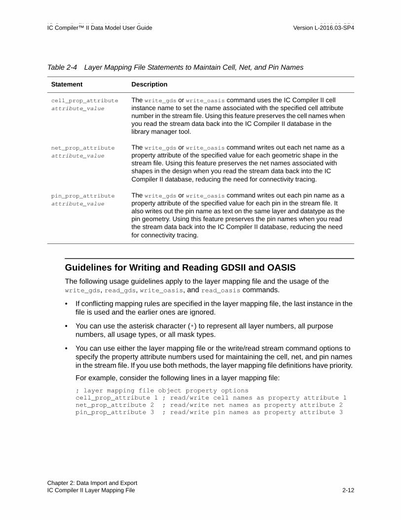
IC Compiler™ II Data Model User Guide L-2016.03-SP4IC Compiler™ II Data Model User Guide Version L-2016.03-SP4
Guidelines for Writing and Reading GDSII and OASIS
The following usage guidelines apply to the layer mapping file and the usage of the write_gds, read_gds, write_oasis, and read_oasis commands.
• If conflicting mapping rules are specified in the layer mapping file, the last instance in the file is used and the earlier ones are ignored.
• You can use the asterisk character (*) to represent all layer numbers, all purpose numbers, all usage types, or all mask types.
• You can use either the layer mapping file or the write/read stream command options to specify the property attribute numbers used for maintaining the cell, net, and pin names in the stream file. If you use both methods, the layer mapping file definitions have priority.
For example, consider the following lines in a layer mapping file:
; layer mapping file object property optionscell_prop_attribute 1 ; read/write cell names as property attribute 1net_prop_attribute 2 ; read/write net names as property attribute 2pin_prop_attribute 3 ; read/write pin names as property attribute 3
Table 2-4 Layer Mapping File Statements to Maintain Cell, Net, and Pin Names
Statement Description
cell_prop_attribute attribute_value
The write_gds or write_oasis command uses the IC Compiler II cell instance name to set the name associated with the specified cell attribute number in the stream file. Using this feature preserves the cell names when you read the stream data back into the IC Compiler II database in the library manager tool.
net_prop_attribute attribute_value
The write_gds or write_oasis command writes out each net name as a property attribute of the specified value for each geometric shape in the stream file. Using this feature preserves the net names associated with shapes in the design when you read the stream data back into the IC Compiler II database, reducing the need for connectivity tracing.
pin_prop_attribute attribute_value
The write_gds or write_oasis command writes out each pin name as a property attribute of the specified value for each pin in the stream file. It also writes out the pin name as text on the same layer and datatype as the pin geometry. Using this feature preserves the pin names when you read the stream data back into the IC Compiler II database, reducing the need for connectivity tracing.
Chapter 2: Data Import and ExportIC Compiler II Layer Mapping File 2-12

IC Compiler™ II Data Model User Guide Version L-2016.03-SP4
These lines override the corresponding options in the write_gds, read_gds, write_oasis, and read_oasis commands, such as the following:
icc2_shell> write_gds -layer_map my_layers.map \ -instance_property 4 -net_property 5 -pin_property 6 my_design.gds
• By default, the write_gds or write_oasis command uses the cut data type numbers defined in the technology file. For example,
Layer "VIA2" cutTblSize = 3 cutNameTbl = (V1SM, V1BAR, V1LRG) # cut names cutWidthTbl = (0.05, 0.05, 0.10) # cut width cutHeightTbl = (0.05, 0.10, 0.10) # cut height cutDataTypeTbl = (5, 10, 15) # cut data types ...
• In this example, the write_gds or write_oasis command maps the V1SM, V1BAR, and V1LRG cuts to data types 5, 10, and 15, respectively. If you do not want this mapping, use the -ignore_cut_datatype_tbl_mapping option with the write_gds or write_oasis command.
• By default, the write_gds or write_oasis command converts all layer data types to 0 for layers not listed in the layer mapping file, or when no layer mapping file is used. To retain the layer data type numbers in these situations, use the -keep_data_type option with the write_gds or write_oasis command.
• By default, the write_gds or write_oasis command writes out text objects in the R0 orientation. To modify the orientation of pin text according to the route access direction, do the following:
icc2_shell> set_app_options \ –name "file.gds.rotate_pin_text_by_access_direction" -value true
icc2_shell> set_app_options \ –name "file.oasis.rotate_pin_text_by_access_direction" -value true
• By default, the write_gds or write_oasis command writes out contact via names using the prefix string “$$”. To specify a different prefix string, do the following:
icc2_shell> set_app_options \ –name "file.gds.contact_prefix" -value "MY_PREFIX"
icc2_shell> set_app_options \ –name "file.oasis.contact_prefix" -value "MY_PREFIX"
• You can save a layer mapping file in a design library by using the set_layer_map_file command. In that case, the saved file is used as the default mapping file when you perform layout validation with the IC Validator tool or parasitic extraction with the StarRC tool. For details, see the man page for the command.
Chapter 2: Data Import and ExportIC Compiler II Layer Mapping File 2-13Chapter 2: Data Import and ExportIC Compiler II Layer Mapping File 2-13

IC Compiler™ II Data Model User Guide L-2016.03-SP4IC Compiler™ II Data Model User Guide Version L-2016.03-SP4
For information about other options for writing or reading stream files and using the layer mapping file, see the applicable man page.
IC Compiler Layer Mapping File Syntax
For backward compatibility with the IC Compiler tool, you can use a layer mapping file written for the IC Compiler Milkyway database format. For example, for the write_gds command, specify the layer mapping file format in one of the following ways:
icc2_shell> write_gds -layer_map map_file_name \ -layer_map_format icc_default ...
icc2_shell> write_gds -layer_map map_file_name \ -layer_map_format icc_extended ...
The icc_default setting uses a layer mapping file written for a Milkyway library in default layer mode, which uses layer numbers 1 through 255. The icc_extended setting uses a layer mapping file written for a Milkyway library in extended layer mode, which uses layer numbers 1 through 4095.
Each line in the layer mapping file shows a Milkyway object type, Milkyway layer, and resulting layer in the output stream. This is the general syntax:
MilkywayObjType[MilkywayNetType][PinCode] MilkywayLayer[:MilkywayDataType] StreamLayer[:StreamDataType]
The first character in the line is the code for the type of Milkyway object to be translated. Use A for all, T for text, or D for data. The optional second character specifies the net type, such as S for signal, P for power, or G for ground. An optional third character specifies the pin code. The Milkyway layer is a name or an integer. The stream layers and data types are integers.
By default, net text and pin text are mapped into the same layer as the associated net or pin. However, you can specify a different layer for net text or pin text in the layer mapping file.
The following example demonstrates the stream-out layer mapping syntax.
T METAL:2 3:5 ; converts text on Milkyway layer ; METAL data Type 2 to GDSII Stream ; layer #3 data type 5 ; Note: If you stream back into ; Milkyway database without using ; the layer map file, this will ; switch your text on layer METAL ; to layer METAL5
TS 16 31:6 ; converts text associated with ; signal nets on Milkyway layer #16 ; to GDSII Stream layer #31 and
Chapter 2: Data Import and ExportIC Compiler Layer Mapping File Syntax 2-14

IC Compiler™ II Data Model User Guide Version L-2016.03-SP4
; data type 6
TP METAL3 16 ; converts text associated with ; power on Milkyway layer METAL3 ; to GDSII Stream layer #16
TG 28 16 ; converts text associated with ; ground on Milkyway layer #28 ; to GDSII Stream layer #16
D METAL2 45 ; converts data on Milkyway layer ; METAL2 to GDSII Stream layer #45
DS 45:2 18:5 ; converts data associated with ; signal nets on Milkyway layer #45 ; data Type 2 to GDSII Stream layer #18 ; data Type 5
A METAL6 3:4 ; converts text and data on ; Milkyway Layer METAL6 to GDSII ; Stream layer #3 and datatype 4
A METAL4 - ; minus sign (hyphen) prevents transfer of all ; text and data on Milkyway layer METAL4
You can add a comment to the file by inserting a semicolon. Text is ignored from the semicolon to the end of the line. A hyphen character in the stream layer position prevents the transfer of all text and data in the specified Milkyway object and layer.
A colon is the delimiter between the stream layer and the optional stream data type. For backward compatibility, you can use a space character alone or a colon followed by white space as the delimiter.
Table 2-5 describes the items used in each line of the layer mapping file.
Table 2-5 IC Compiler Layer Mapping File Syntax
Variable Description
MilkywayObjType The code for the type of object in the data to be translated:
A for all types
T for text
D for data
Chapter 2: Data Import and ExportIC Compiler Layer Mapping File Syntax 2-15Chapter 2: Data Import and ExportIC Compiler Layer Mapping File Syntax 2-15

IC Compiler™ II Data Model User Guide L-2016.03-SP4IC Compiler™ II Data Model User Guide Version L-2016.03-SP4
MilkywayNetType The code for the net type of the object in the data to be translated:
S for signal
P for power
G for ground
C for clock
U for Up conduction layer (upper layer in a via). Example: metal2 in an m1/m2 via
D for Down conduction layer (lower layer in a via). Example: metal1 in an m1/m2 via
X for power and ground wires or contacts with a “signal” or “tie-off” routing type
A for all net types
Note that U and D are used only for via and flattened via objects. They override any other net type set for the layer when the layer is in a via.
If MilkywayNetType is omitted, the tool maps all Milkyway data of the specified object type to the specified stream layer.
If MilkywayNetType is included, the tool examines every object of the object type to determine its net type and maps it to the layer you specify. If an object has no net or a net has no type, the tool assumes that it is a signal net.
If a layer file contains contradictory lines, the last line overrides any previous line. For example, if an earlier line of a layer file specifies mapping for a particular object or net type and a later line specifies mapping for the same object type but no net type, the tool translates all data of the specified object type as defined by the later line.
PinCode Optional. Can be used when only the Pin geometry or Terminal (top-level pin) geometry in the Milkyway database needs to be translated:
T for terminal geometries of the current design
P for terminal geometries of the current design, as well as the physical pin geometries of the child cells, depending on the child depth option.
Note: PinCode P and T only work when MilkywayNetType is set to A. Otherwise, the PinCode rule is ignored.
MilkywayLayer Specifies the name or number, from 1 to 255 (1 to 4095 in extended layer mode), of a layer to be translated and defined in the technology file.
Table 2-5 IC Compiler Layer Mapping File Syntax (Continued)
Variable Description
Chapter 2: Data Import and ExportIC Compiler Layer Mapping File Syntax 2-16

IC Compiler™ II Data Model User Guide Version L-2016.03-SP4
The write_gds or write_oasis command writes geometries into reserved layers by mapping the tool layer numbers according to the following table.
MilkywayDataType The data type of the Milkyway data to be translated: an integer from 0 to 4095.
StreamLayer Specifies the number of the stream layer to which the objects of MilkywayObjType on MilkywayLayer are translated. Use an integer from 0 to 32767 or use a hyphen character (-) to ignore the Milkyway object and layer during translation.
StreamDataType Specifies the number of the stream data type to which objects of MilkywayObjType and MilkywayNetType, if given, on MilkywayLayer are translated. Use an integer from 0 to 32767.
Table 2-6 Milkyway Layer Numbers and Blockage Usage
Milkyway layer number (default)
Milkyway layer number (extended)
Blockage layer
212 4025 polyBlockage
216 4029 metal4Blockage
217 4030 via3Blockage
218 4031 metal1Blockage
219 4032 metal2Blockage
220 4033 metal3Blockage
223 4036 polyContBlockage
224 4037 via1Blockage
225 4038 via2Blockage
Table 2-5 IC Compiler Layer Mapping File Syntax (Continued)
Variable Description
Chapter 2: Data Import and ExportIC Compiler Layer Mapping File Syntax 2-17Chapter 2: Data Import and ExportIC Compiler Layer Mapping File Syntax 2-17

IC Compiler™ II Data Model User Guide L-2016.03-SP4IC Compiler™ II Data Model User Guide Version L-2016.03-SP4
Changing Object Names
The IC Compiler II tool follows certain naming conventions for ports, cells, and nets. When you export a design to a new format such as Verilog, DEF, LEF, or GDSII, you might need to have the object names follow naming conventions of the external tool that are different from IC Compiler II naming conventions.
Before you export a design, you can use the change_names command to change the names of cells, nets, and ports so that the new names follow the required naming conventions. The IC Compiler II tool has a built-in capability to convert object names to conform to Verilog requirements. You can also create your own naming conversion rules.
See Also
• Changing Object Names Using Custom Rules
• Changing Object Names for Verilog Output
Changing Object Names Using Custom Rules
Using the define_name_rules and change_names commands, you can change the names of ports, cells, and nets in the design to conform to specified naming conventions. The name-changing process can perform the following types of changes:
• Force the name of any net connected to a port to match the port name
• Force all port, cell, and net names to be unique across all objects
• Change all occurrences of a given string in object names to a new string
• Restrict the first character, last character, or all characters of object names to a given list of characters
• Prohibit the usage of a given list of characters as the first character, last character, or all characters of object names
• Prohibit the usage of a given list of words as object names
• Restrict the number of characters in each name to a specified maximum limit
The following diagram shows the typical flow for changing the names of objects in the design.
Chapter 2: Data Import and ExportChanging Object Names 2-18

IC Compiler™ II Data Model User Guide Version L-2016.03-SP4
Figure 2-1 Typical Flow for Changing Object Names
The following example changes each occurrence of the string “address” or “data” to “ADR” or “D”, respectively, in all port names.
1. Define the name conversion rule.
icc2_shell> define_name_rules UCports -type port \ -map {{"address","ADR"},{"data","D"}}1
This defines a rule called “UCports” (uppercase ports), which maps the string “address” to “ADR” and the string “data” to “D” in port names.
2. (Optional) Report the rule just defined and verify its behavior.
icc2_shell> report_name_rules UCports... Rules Name: UCports ...
define_name_rules rule_name ...
Define the desired name conversion rule
report_name_rules rule_name
Report name of newly defined conversion rule (optional)
report_names -rules rule_name
Report the names in the design that will be changed (optional)
change_names -rules rule_name -hierarchy
Change the names in the design according to the rule
report_ports, report_cells, report_nets, write_*
Report the new names; write out the design using new names
Chapter 2: Data Import and ExportChanging Object Names 2-19Chapter 2: Data Import and ExportChanging Object Names 2-19

IC Compiler™ II Data Model User Guide L-2016.03-SP4IC Compiler™ II Data Model User Guide Version L-2016.03-SP4
Object Max Repl Rem Type Len Char Chrs Prefix Allowed Chars ----------------------------------------------------------------- Port none '_' no P Mapping String: "{"address","ADR"}, {"data","D"}" Cell none '_' no U Net none '_' no N 1
3. (Optional) Report the names that would be changed by applying the rule, without actually making the changes, and verify that the proposed changes are correct.
icc2_shell> report_names -rules UCports ... Design Type Object New Name ------------------------------------------------------------ my_design_mp port address[27] ADR[27] my_design_mp port address[26] ADR[26] my_design_mp port address[25] ADR[25] ... my_design_mp port data[31] D[31] my_design_mp port data[30] D[30] my_design_mp port data[29] D[29] ...
4. Change the names in the design according to the rule.
icc2_shell> change_names -rules UCports -hierarchy Information: Using name rules 'UCports'. Information: 62 objects (60 ports, 2 bus ports, 0 cells & 0 nets) changed in design 'my_design_mp'.
To apply the name changes across multiple levels of the physical hierarchy, use the -include_sub_blocks option with the -hierarchy option:
icc2_shell> change_names -rules UCports -hierarchy -include_sub_blocks...
5. (Optional) Report the object names and verify that they have been changed correctly.
icc2_shell> report_ports... Pin Cap Wire Cap Min Max Min MaxPort Dir rise/fall rise/fall rise/fall rise/fall --------------------------------------------------------------------ADR[0] out 0.00/0.00 0.00/0.00 0.00/0.00 0.00/0.00 ADR[10] out 0.00/0.00 0.00/0.00 0.00/0.00 0.00/0.00 ADR[11] out 0.00/0.00 0.00/0.00 0.00/0.00 0.00/0.00 ...D[0] inout 0.00/0.00 0.00/0.00 0.00/0.00 0.00/0.00 D[10] inout 0.00/0.00 0.00/0.00 0.00/0.00 0.00/0.00 D[11] inout 0.00/0.00 0.00/0.00 0.00/0.00 0.00/0.00
Chapter 2: Data Import and ExportChanging Object Names 2-20

IC Compiler™ II Data Model User Guide Version L-2016.03-SP4
...
When you save or export the design, the design data reflects the new names.
For information about the various rules you can use to change port, cell, and net names, see the man page for the define_name_rules command.
See Also
• Changing Object Names for Verilog Output
Changing Object Names for Verilog Output
Before you export a design in Verilog format by using the write_verilog command, use the change_names command to change all the object names to conform to Verilog conventions:
icc2_shell> current_block{my_lib:my_design/done.design}
icc2_shell> change_names -rules verilog -hierarchy Information: Using name rules 'verilog'. Information: 321 objects (0 ports, 0 bus ports, 0 cells & 321 nets) changed in design 'my_design'. 1 icc2_shell> write_verilog my_design.v1
To see the details of the Verilog naming rules, use the report_name_rules command:
icc2_shell> report_name_rules verilog...Rules Name: verilog Collapse name space: true Equal port and net names: true Equal inout port and net names: true Check internal net name: true Target bus naming style: %s[%d] Remove irregular port bus: true Check bus indexing: true Check bus indexing use type info: false Remove port bus: false Case insensitive: false Add dummy nets: false Reserved words: not defined...
For a full explanation of each type of name change, see the man page for the define_name_rules command.
Chapter 2: Data Import and ExportChanging Object Names 2-21Chapter 2: Data Import and ExportChanging Object Names 2-21

IC Compiler™ II Data Model User Guide L-2016.03-SP4IC Compiler™ II Data Model User Guide Version L-2016.03-SP4
See Also
• Changing Object Names Using Custom Rules
Chapter 2: Data Import and ExportChanging Object Names 2-22

3Working With Design Data 3
When you work with a design in the IC Compiler II tool, you open and edit the design view of a block stored in a design library.
You can query and edit the design data as described in the following topics:
• Application Options
• Objects and Collections
• Bus and Name Expansion
• Design Hierarchy
• Technology Data Access
• Reporting Design Information
• Polygon Manipulation
• Undoing and Redoing Changes to the Design
• Schema Versions
3-1

IC Compiler™ II Data Model User Guide L-2016.03-SP4IC Compiler™ II Data Model User Guide Version L-2016.03-SP4
Application Options
You set the tool’s application options by using the set_app_options command. These options control various aspects of tool behavior. For example, to set the maximum allowed coarse placement density for the current block:
icc2_shell> set_app_options -name place.coarse.max_density -value 0.6place.coarse.max_density 0.6
Application options use the following naming convention:
category[.subcategory].option_name
where category (such as place) is the tool feature affected by the option and subcategory (such as coarse) is a refinement of the feature affected by the option.
To get a list of all available application options, use the get_app_options command:
icc2_shell> get_app_optionsshell.common.tmp_dir_path shell.common.enable_line_editing shell.comm.line_editing_mode shell.common.collection_result_...
To restrict the list of reported application options, provide a pattern string:
icc2_shell> get_app_options place.*place.coarse.channel_detect_mode place.coarse.congestion_analysis_effort ...icc2_shell> get_app_options *lib*design.edit_read_only_libs link.user_units_from_first_library ... ...
Each application option applies either globally or to a specific block:
• Global application options apply everywhere within the current session. They are not stored and are not carried over from one session to the next. To retain these option settings, you can set them in your .synopsys_icc2.setup file.
• Block-level application options apply only to the block on which they are set. They are saved with the block in the design library and are persistent across tool sessions. Before you can set a block’s application options, the block must be open.
You can determine whether an application option is global or block-level by using the report_app_options command.
To use the GUI to view, search, and edit application options, choose File > Application Options. This opens the Application Options dialog box, shown in the following figure.
Chapter 3: Working With Design DataApplication Options 3-2

IC Compiler™ II Data Model User Guide Version L-2016.03-SP4
Figure 3-1 Application Options Dialog Box
In the Application Options dialog box, to view the man page for the highlighted application option, click the question mark icon in the upper-right corner.
For more information about application options, see
• Setting Application Options
• Querying Application Options
• Help on Application Options
• Man Pages for Application Options
• User Default for Application Options
• Resetting Application Options
Chapter 3: Working With Design DataApplication Options 3-3Chapter 3: Working With Design DataApplication Options 3-3

IC Compiler™ II Data Model User Guide L-2016.03-SP4IC Compiler™ II Data Model User Guide Version L-2016.03-SP4
Setting Application Options
To set an application option, use the set_app_options command:
icc2_shell> set_app_options -name link.verbose -value truelink.verbose true
To set a block-level application option on a block other than the current block:
icc2_shell> set_app_options -block des_A -name link.verbose -value truelink.verbose true
To set multiple application options in a single command:
icc2_shell> set_app_options -list \ {link.verbose true link.reference_limit 8}link.reference_limit 8 link.verbose true
Alternatively, if the options belong to the same category, you can do this:
icc2_shell> set_app_options -category link \ -list {verbose true reference_limit 8}link.reference_limit 8 link.verbose true
See Also
• Application Options
• Querying Application Options
• User Default for Application Options
• Resetting Application Options
Querying Application Options
To get an application option setting, use the get_app_option_value command:
icc2_shell> get_app_option_value -name link.verbosetrue
To get a block-level application option setting for a block other than the current block, use the -block option.
To get the default setting for an application option, use the -system_default option:
icc2_shell> get_app_option_value -name link.verbose -system_defaultfalse
Chapter 3: Working With Design DataApplication Options 3-4

IC Compiler™ II Data Model User Guide Version L-2016.03-SP4
To get all the attributes of an application option, use the -details option:
icc2_shell> get_app_option_value -name link.verbose -detailsname link.verbose value_type bool default_value false help {Verbose messages while linking} status basic minimum_value {} maximum_value {} allowed_values {} is_obsolete false is_global_only false is_read_only false is_persistent true is_subscripted false is_design_cell_scoped true is_lib_cell_scoped false
To report multiple application option settings, only the global options, or only the user-set options, use the report_app_options command:
icc2_shell> report_app_options link* ...Name Type Value ... default Scope ---------------------------- -------------- ------ ----------- --------link.bit_blast_naming_style list_of string {} ... ... blocklink.prefer_frame bool -- ... ... globallink.undo_enabled bool -- ... ... global...
icc2_shell> report_app_options link* -global ...Name Type Value ... System-default---------------------------- -------------- ------ -------------------link.prefer_frame bool -- ... truelink.undo_enabled bool -- ... true...
icc2_shell> report_app_options -non_default # Report user-set options...Name Type Value ... System-default Scope------------------------ ------ ------- --- --------------- -------place.coarse.max_density float 0.70 ... 0 block------------------------ ------ ------- --- --------------- -------1
icc2_shell> report_app_options # Report all options...
See Also
• Application Options
• Setting Application Options
• Help on Application Options
• Man Pages for Application Options
• User Default for Application Options
• Resetting Application Options
Chapter 3: Working With Design DataApplication Options 3-5Chapter 3: Working With Design DataApplication Options 3-5

IC Compiler™ II Data Model User Guide L-2016.03-SP4IC Compiler™ II Data Model User Guide Version L-2016.03-SP4
Help on Application Options
You can use the help_app_options command to get help on using application options:
icc2_shell> help_app_options Categories of the registered application options are: abstract clock_opt.congestion clock_opt.flow clock_opt.hold ... link ... icc2_shell> help_app_options -category linklink.bit_blast_naming_style # naming style for bit blasted ...link.prefer_frame # Prefer blocks with FRAME view ...link.reference_limit # Maximum number of unresolved ...link.require_physical # Require sub-blocks to have ...link.undo_enabled # Allow link_design command to be ...link.user_units_from_first_library # Set user units to the units of ...link.verbose # Verbose messages while linking
icc2_shell> help_app_options -category link -scope blocklink.bit_blast_naming_style # naming style for bit blasted ...link.reference_limit # Maximum number of unresolved ...link.verbose # Verbose messages while linking
icc2_shell> help_app_options link.undo_enabledlink.undo_enabled # Allow link_block command to be undoable
icc2_shell> help_app_options link.undo_enabled -verbosename link.undo_enabledvalue_type booldefault_value falsehelp Allow link_block command to be undoable... ...is_read_only falseis_persistent falseis_subscripted falseis_design_cell_scoped falseis_lib_cell_scoped false
See Also
• Application Options
• Setting Application Options
• Querying Application Options
• Man Pages for Application Options
Chapter 3: Working With Design DataApplication Options 3-6

IC Compiler™ II Data Model User Guide Version L-2016.03-SP4
Man Pages for Application Options
To view the man page for a specific application option, use the man command:
icc2_shell> man link.reference_limit...
NAME link.reference_limit Specifies the maximum number of detailed unresolved reference errors display for each block when linking ...TYPE integer
DEFAULT 12
DESCRIPTION In many cases, many link errors have the same root cause ... ...SEE ALSO link_block(2) get_app_option_value(2) ...
To view the man page for all application options under a top-level category, use the man command to view the man page for category_options:
icc2_shell> man link_options ...DESCRIPTION ...link.bit_blast_naming_style ...link.prefer_frame ...link.reference_limit ......
See Also
• Application Options
• Setting Application Options
• Querying Application Options
• Help on Application Options
Chapter 3: Working With Design DataApplication Options 3-7Chapter 3: Working With Design DataApplication Options 3-7

IC Compiler™ II Data Model User Guide L-2016.03-SP4IC Compiler™ II Data Model User Guide Version L-2016.03-SP4
User Default for Application Options
You can optionally set a user default for an application option. The user default has higher priority than the system default but lower priority than an explicit setting for the option. The user default applies only to the current session and is not saved.
For example, the system default for the place.coarse.max_density application option is 0.0, so that value applies to all blocks by default. To set the user default to a different value, use the set_app_options command with the -as_user_default option:
icc2_shell> set_app_options -as_user_default \ -name place.coarse.max_density -value 0.65place.coarse.max_density 0.65
icc2_shell> report_app_options place.coarse.max_density...Name Type Value User-default System-default ...------------------------ ------ ------ ------------- --------------- ---place.coarse.max_density float -- 0.65 0 ...------------------------ ------ ------ ------------- --------------- ---
The new default, 0.65, applies to all blocks in the current session that do not have an explicit value set.
You can override the user default for a particular block by setting the place.coarse.max_density application option to the desired value for the block:
icc2_shell> current_block{lib_A:block3.design}icc2_shell> set_app_options -name place.coarse.max_density -value 0.70place.coarse.max_density 0.7
icc2_shell> report_app_options place.coarse.max_density...Name Type Value User-default System-default ...------------------------ ------ ------ ------------- --------------- ---place.coarse.max_density float 0.70 0.65 0 ...------------------------ ------ ------ ------------- --------------- ---
The order of priority is “Value” first, then “User-default,” and “System-default” last.
See Also
• Application Options
• Setting Application Options
• Resetting Application Options
Chapter 3: Working With Design DataApplication Options 3-8

IC Compiler™ II Data Model User Guide Version L-2016.03-SP4
Resetting Application Options
To reset an application option so that it has no explicitly assigned value, use the reset_app_options command:
icc2_shell> reset_app_options place.coarse.max_density1icc2_shell> report_app_options place.coarse.max_density...Name Type Value User-default System-default ...------------------------ ------ ------ ------------- --------------- ---place.coarse.max_density float -- 0.65 0 ...------------------------ ------ ------ ------------- --------------- ---
The reset_app_options command removes the “Value” setting and allows the “User-default” setting to apply (if any), or the “System-default” to apply if there is no user default.
To reset a user default setting, use the reset_app_options command with the -user_default option:
icc2_shell> reset_app_options place.coarse.max_density -user_default 1icc2_shell> report_app_options place.coarse.max_density...Name Type Value User-default System-default ...------------------------ ------ ------ ------------- --------------- ---place.coarse.max_density float -- -- 0 ...------------------------ ------ ------ ------------- --------------- ---
See Also
• Application Options
• Setting Application Options
• User Default for Application Options
Objects and Collections
The IC Compiler II infrastructure supports a full set of design-related objects and Tcl commands to create, query, modify, and remove these objects, including the following types:
• Logical objects such as cells, ports, and nets
• Timing data objects such as modes and corners
• Physical objects such as shapes, vias, tracks, and blockages
• Reference library objects such as libraries, library cells, and library pins
Chapter 3: Working With Design DataObjects and Collections 3-9Chapter 3: Working With Design DataObjects and Collections 3-9

IC Compiler™ II Data Model User Guide L-2016.03-SP4IC Compiler™ II Data Model User Guide Version L-2016.03-SP4
To get the full list of object types, use the following command:
icc2_shell> get_defined_attributes -return_classesblock bound bound_shape budget_clock budget_path_type ...bundle_segment bundle cell clock clock_balance_group clock_group ......
The tool has commands to create, get, and remove specific types of objects, such as:
create_block get_blocks remove_blockscreate_net get_nets remove_netscreate_tech get_techs remove_tech
You can also operate on objects of mixed types in a collection by using commands such as the following:
• move_objects – move objects by a specified amount or to a specified location
• flip_objects – flip objects around a specified axis
• rotate_objects – rotate objects by a specified angle or to a specified orientation
• remove_objects – remove objects from the design
Some types of objects have special-purpose commands that apply only to specific object types, such as report_lib, add_to_bound, set_lib_cell_purpose, and connect_net.
See Also
• Common Design Objects
• Object Attributes
• Querying Objects
• Removing Objects
Chapter 3: Working With Design DataObjects and Collections 3-10

IC Compiler™ II Data Model User Guide Version L-2016.03-SP4
Common Design Objects
Table 3-1 lists some common design objects and the commands to query them. These objects are provided as examples; there are many more objects not shown in the table. For a complete list of object types, use the get_defined_attributes -return_classes command.
Table 3-1 Commands to Query Some Common Design Objects
Object Command Description
Blockages get_pin_blockages
report_pin_blockages
get_placement_blockages
get_routing_blockages
Returns a collection of pin blockages.
Displays information about the pin blockages.
Returns a collection of placement blockages
Returns a collection of routing blockages
Bounds get_bounds
get_bound_shapes
report_bounds
Returns a collection of placement bounds.
Returns a collection of shapes associated with placement bounds.
Displays information about the placement bounds.
Bus ports get_port_buses
report_port_buses
Creates a collection of port buses from the current design.
Displays port bus information within the design.
Cells get_cells
report_cells
Returns a collection of cell instances. By default, the tool uses the logic hierarchy to resolve cell names. To use the physical hierarchy to resolve cell names, use the -physical_context option.
Displays information about the cell instances.
Clocks get_clocks
get_clock_groups
get_generated_clocks
report_clocks
Returns a collection of clocks
Returns a collection of clock groups.
Returns a collection of generated clocks.
Reports information about clocks.
Core area get_core_area Returns a collection that contains the core area.
Chapter 3: Working With Design DataObjects and Collections 3-11Chapter 3: Working With Design DataObjects and Collections 3-11

IC Compiler™ II Data Model User Guide L-2016.03-SP4IC Compiler™ II Data Model User Guide Version L-2016.03-SP4
Guides get_io_guides
report_io_guides
get_pin_guides
report_pin_guides
Returns a collection of I/O guides.
Displays information about the I/O guides.
Returns a collection of pin guides.
Displays information about the pin guides.
I/O rings get_io_rings
report_io_rings
Returns a collection of I/O rings.
Displays information about I/O rings.
Modules get_modules Returns a collection of logic hierarchies in memory, as defined in the Verilog netlist.
Nets get_nets
get_shapes
report_nets
Returns a collection of logical nets. To return a collection of physical nets, use the -physical_context option.
Returns a collection of shapes associated with nets.
Displays information about the nets.
Pins get_pins Returns a collection of logical pins. To return a collection of physical pins, use the -physical_context option.
Ports get_ports
report_ports
Returns a collection of logical ports. To return a collection of physical ports, use the -physical_context option.
Displays information about the ports.
Power domains
get_power_domains
get_domain_elements
report_power_domains
Returns a collection of power domains.
Returns a collection of elements associated with power domains.
Displays information about the power domains.
Power regions
get_pg_regions
report_pg_regions
Returns a collection of power and ground (PG) regions.
Displays information about the PG regions.
Site rows get_site_rows Returns a collection of site rows.
Table 3-1 Commands to Query Some Common Design Objects (Continued)
Object Command Description
Chapter 3: Working With Design DataObjects and Collections 3-12

IC Compiler™ II Data Model User Guide Version L-2016.03-SP4
Object Attributes
Each type of design object has a list of predefined attributes. You can query these attributes to get information about the design. In some cases, you can modify the attribute settings to control the design implementation.
To determine the attributes associated with an object type, use the list_attributes command. For example, to list the attributes of nets:
icc2_shell> list_attributes -application -class net...Properties: A - Application-defined U - User-defined I - Importable from design/library (for user-defined) S - Settable B - Subscripted
Attribute Name Object Type Properties Constraints-----------------------------------------------------------------------antenna_rule_name net string A,S base_name net string A bbox net rect A dont_touch net boolean A,S
Supply nets
get_supply_nets
get_related_supply_nets
report_supply_nets
Returns a collection of supply nets.
Returns a collection of related supply nets.
Displays information about the supply nets.
Supply ports
get_supply_ports
report_supply_ports
Returns a collection of supply ports.
Displays information about the supply ports.
Terminals get_terminals Returns a collection of terminals.
Tracks get_tracks Returns a collection of tracks.
Vias get_vias Returns a collection of vias.
Voltage areas
get_voltage_areas
get_voltage_area_shapes
report_voltage_areas
Returns a collection of voltage areas.
Returns a collection of shapes associated with voltage areas.
Displays information about the voltage areas.
Table 3-1 Commands to Query Some Common Design Objects (Continued)
Object Command Description
Chapter 3: Working With Design DataObjects and Collections 3-13Chapter 3: Working With Design DataObjects and Collections 3-13

IC Compiler™ II Data Model User Guide L-2016.03-SP4IC Compiler™ II Data Model User Guide Version L-2016.03-SP4
full_name net string A has_topology net boolean A ...
The -application option is necessary to report the predefined object attributes. By default, the command reports only user-defined attributes. In the “Properties” column, the letter “A” means “application-defined” attribute, and the letter “S” means “settable” attribute.
You can set a “settable” attribute of an object by using the set_attribute command:
icc2_shell> set_attribute -objects [get_nets net16] -name dont_touch \ -value true{{net16}}icc2_shell> get_attribute -objects [get_nets net16] -name dont_touchtrue
An attribute that is not “settable” is read-only; you cannot change it directly by using the set_attribute command. For example, the bbox (bounding box) attribute of a net is not settable. However, when you edit or optimize a net, the tool automatically updates the bbox attribute to reflect the net’s bounding box.
Another way to determine the attributes associated with an object type is to use the get_defined_attributes command:
icc2_shell> get_defined_attributes -application -class netantenna_rule_name base_name bbox dont_touch full_name is_bbt_object is_global is_ideal is_in_bundle is_physical is_rdl is_shadow is_tie_high_net is_tie_low_net max_layer max_layer_mode ...
For descriptions of the attributes, see the man page for object_name_attributes. For example, for information about the net attributes:
icc2_shell> man net_attributes... base_name A string attribute for the name of a net. This name does not include the instance path prefix.
full_name A string attribute for the name of a net. This name includes a prefix for the instance path to this net. is_global A Boolean attribute. Possible values are "true" and "false". Global nets are those tied to logic 0 and logic 1. ...
Chapter 3: Working With Design DataObjects and Collections 3-14
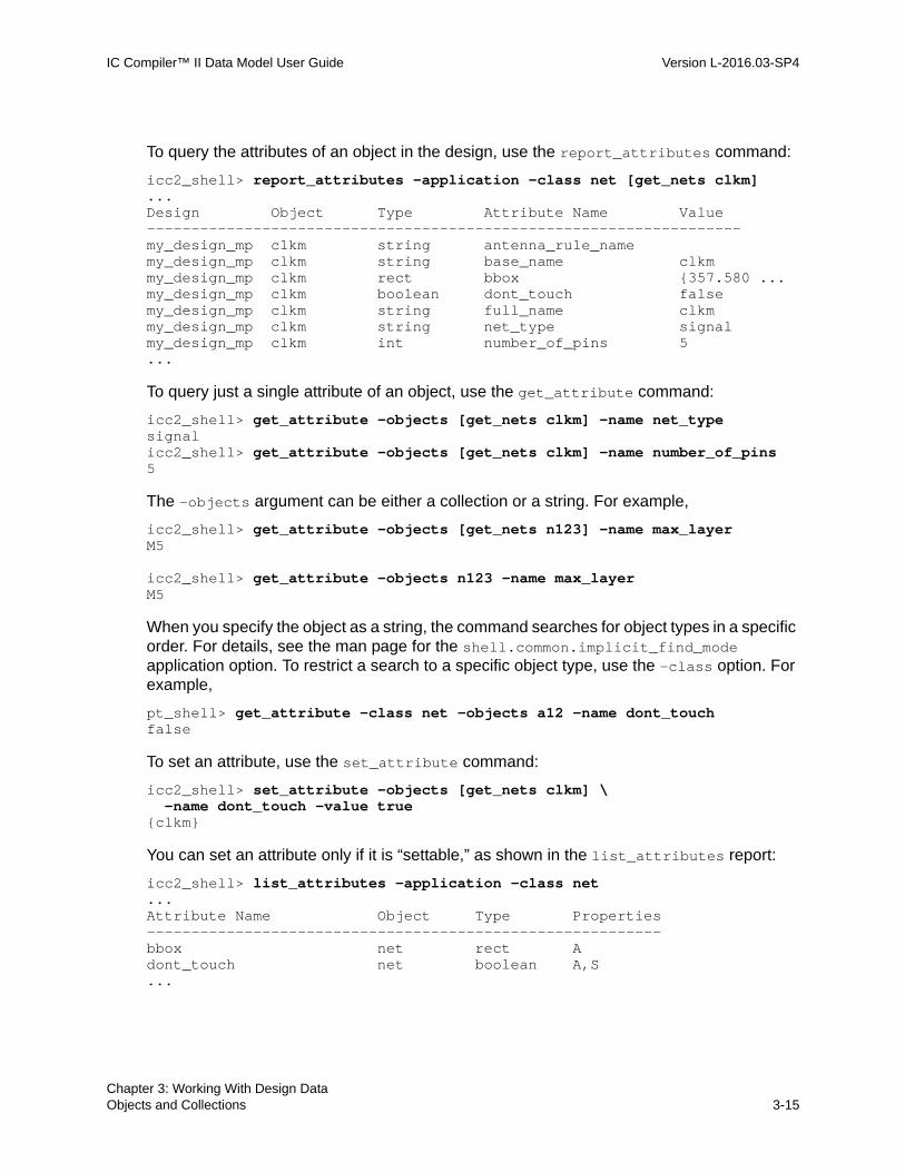
IC Compiler™ II Data Model User Guide Version L-2016.03-SP4
To query the attributes of an object in the design, use the report_attributes command:
icc2_shell> report_attributes -application -class net [get_nets clkm]...Design Object Type Attribute Name Value-------------------------------------------------------------------my_design_mp clkm string antenna_rule_name my_design_mp clkm string base_name clkm my_design_mp clkm rect bbox {357.580 ...my_design_mp clkm boolean dont_touch false my_design_mp clkm string full_name clkm my_design_mp clkm string net_type signalmy_design_mp clkm int number_of_pins 5 ...
To query just a single attribute of an object, use the get_attribute command:
icc2_shell> get_attribute -objects [get_nets clkm] -name net_typesignalicc2_shell> get_attribute -objects [get_nets clkm] -name number_of_pins5
The -objects argument can be either a collection or a string. For example,
icc2_shell> get_attribute -objects [get_nets n123] -name max_layerM5
icc2_shell> get_attribute -objects n123 -name max_layerM5
When you specify the object as a string, the command searches for object types in a specific order. For details, see the man page for the shell.common.implicit_find_mode application option. To restrict a search to a specific object type, use the -class option. For example,
pt_shell> get_attribute -class net -objects a12 -name dont_touchfalse
To set an attribute, use the set_attribute command:
icc2_shell> set_attribute -objects [get_nets clkm] \ -name dont_touch -value true{clkm}
You can set an attribute only if it is “settable,” as shown in the list_attributes report:
icc2_shell> list_attributes -application -class net...Attribute Name Object Type Properties----------------------------------------------------------bbox net rect A dont_touch net boolean A,S...
Chapter 3: Working With Design DataObjects and Collections 3-15Chapter 3: Working With Design DataObjects and Collections 3-15

IC Compiler™ II Data Model User Guide L-2016.03-SP4IC Compiler™ II Data Model User Guide Version L-2016.03-SP4
In the “Properties” column, the letter “A” means “application-defined attribute” and the letter “S” means “settable attribute.”
Querying Objects
You can get information about objects in the design several different ways. In the GUI display, when you hover over an object, a ToolTip displays basic information about that object. For more information about that object, right-click it and choose Properties.
At the shell prompt, you can use the report_* commands (for example, report_nets) to report some types of objects, or the get_* commands (for example, get_nets) to create a collection of objects. You can use a collection as input to another command, or set a variable to a collection for future use:
icc2_shell> get_nets test*{test_mode test_se test_si test_si_1 ...}
icc2_shell> set my_test_nets [get_nets test*]{test_mode test_se test_si test_si_1 ...}
icc2_shell> report_nets [get_nets test*]...Net Fanout Fanin Pins-----------------------------------------------test_mode 1 1 2test_se 1 1 2test_s1 1 1 2test_s_1 1 1 2...
icc2_shell> report_nets $my_test_nets... (generates the same report) ...
For more information about collections, see the collections man page:
icc2_shell> man collections...
For more information about using the get_* commands, see
• Query by Location
• Query by Association
• Query in Physical Context
• Cascaded Attributes
Chapter 3: Working With Design DataObjects and Collections 3-16

IC Compiler™ II Data Model User Guide Version L-2016.03-SP4
Query by Location
To search for objects at a specific location or within a specified rectangular region, use one of the following methods:
• Use the -at, -intersect, -touching, or -within options with the get_* command.
Use this method when you are looking for objects of a single type. Figure 3-2 shows the behavior of these options. The behavior is the same as in the IC Compiler tool.
• Use the get_objects_by_location command.
Use this method when you are looking for objects of more than one type. Figure 3-3 shows the default behavior of the -at, -intersect, -touching, and -within options with the get_objects_by_location command. To change the behavior of these options to match the IC Compiler tool behavior and the get_* behavior, set the design.enable_icc_region_query application option to true.
Figure 3-2 get_* by Location Behavior
-at {15 0}
(10,10)
U2
U5
U3
U1
U4
U6(0,0)
-within {{0 0}{10 10}}
-intersect {{0 0}{10 10}}
-touching {{0 0}{10 10}}
Chapter 3: Working With Design DataObjects and Collections 3-17Chapter 3: Working With Design DataObjects and Collections 3-17

IC Compiler™ II Data Model User Guide L-2016.03-SP4IC Compiler™ II Data Model User Guide Version L-2016.03-SP4
Figure 3-3 get_objects_by_location Behavior
When you search within a box using the -within option, the get_* commands get only the objects entirely within the box. By default, the get_objects_by_location command gets those objects entirely within the box and those that touch the boundary from inside.
When you search for objects that touch a box using the -touching option, the get_* commands get only the objects that touch the boundary from inside. By default, the get_objects_by_location command gets the objects entirely within the box and those that touch the boundary from inside.
When you search for objects that intersect a box using the -intersect option, the get_* commands get the objects that touch or cross the box boundary. By default, the get_objects_by_location command gets only the objects that cross the box boundary; those that only touch the boundary from inside or outside are not included.
When you specify an x y point using the -at option, the get_* commands and the get_objects_by_location command get all objects at the specified point.
For example, to get all objects at (15,0):
icc2_shell> get_objects_by_location -at {15 0} {U6}
To get all nets and cells at (0,0):
icc2_shell> get_objects_by_location -at {0 0} -classes {net cell} \Warning: Nothing implicitly matched '*' (SEL-003)
To get all cells within the box defined by (0,0) and (10,10):
icc2_shell> get_cells -within {{0 0} {10 10}}{U1}
-at {15 0}
(10,10)
U2
U5
U3
U1
U4
U6(0,0)
-within {{0 0}{10 10}}-touching {{0 0}{10 10}}
-intersect {{0 0}{10 10}}
Chapter 3: Working With Design DataObjects and Collections 3-18

IC Compiler™ II Data Model User Guide Version L-2016.03-SP4
icc2_shell> get_objects_by_location -within {{0 0} {10 10}} \ -classes cell {U1 U2}
To get all cells that intersect the boundary of the box defined by (0,0) and (10,10):
icc2_shell> get_cells -intersect {{0 0} {10 10}}{U2 U3 U4 U5}
icc2_shell> get_objects_by_location -intersect {{0 0} {10 10}} \ -classes cell{U4 U5}
Query by Association
When you use a get_* command, in addition to finding objects by name, you can find objects associated with or connected to specific objects by using the -of_objects option. For example, to get the cells connected to a given net:
icc2_shell> get_cells -of_objects [get_nets net32] {U83 U75 U18}
or to get the nets connected to a given cell:
icc2_shell> get_nets -of_objects [get_cells U83] {net24 net32 net91}
You can use the get_cells command with the -of_objects option to get the cells associated with other cells or with objects such as pins, nets, bounds, I/O guides, I/O rings, voltage areas, voltage area shapes, edit groups, or power strategies.
Query in Physical Context
By default, a get_* command searches for objects in the logical context, using the design netlist. To search for objects in the physical context instead, use the -physical_context option.
For example, the following command gets all nets in the logical context (nets in the design netlist):
icc2_shell> get_nets {net24 net32 ... }
The following command gets all nets in the physical context (physical nets in the design view):
icc2_shell> get_nets -physical_context{U18/sr0 U18/um18 ... }
Chapter 3: Working With Design DataObjects and Collections 3-19Chapter 3: Working With Design DataObjects and Collections 3-19

IC Compiler™ II Data Model User Guide L-2016.03-SP4IC Compiler™ II Data Model User Guide Version L-2016.03-SP4
When you search for an object by name without the -physical_context option, the command matches the specified pattern with the base name of the object. Conversely, when you use the -physical_context option, the command matches the specified pattern with the full name of the object in the physical hierarchy:
icc2_shell> get_cells -physical_context *I_SDRAM_IF* {I_ORCA_TOP/I_SDRAM_IF/sd_mux_dq_out_11 …}
The -physical_context option is available in commands that get logical objects, such as get_cells, get_pins, get_ports, and get_nets; and the report_hierarchy command.
When you use the -physical_context option, a subblock is treated as a single physical cell, so you cannot use this option from the top-level block to search for logical objects in subblocks, except for a command in the following form:
icc2_shell> get_cells –physical_context –of_objects subblock1...
In this case, the command returns all the physical cells of subblock1.
Cascaded Attributes
For collection-type attributes that point to other design objects, you can query the attributes of that object directly from the current object by using cascaded attributes.
For example, the owner attribute of a via points to the via’s owner net. You can query an attribute of the owner net directly from the via object with the get_attribute command by cascading the net attribute with the via’s owner attribute.
For example, to get the owner net of via VIA_S1:
icc2_shell> get_attribute -objects [get_vias VIA_S1] -name owner{ISTACK/net12}
To get the number of wires in the via owner net: :
icc2_shell> get_attribute -objects [get_vias VIA_S1] \ -name owner.number_of_wires3
To get all the vias belonging to the owner net:
icc2_shell> get_vias -filter owner.full_name==ISTACK/net12 {VIA_S1 VIA_S2 VIA_S3 VIA_S4}
You can cascade any number of attributes, such as the three in the following example:
icc2_shell> get_attribute [get_vias VIA_S1] owner.top_block.top_module{ORCA}
Chapter 3: Working With Design DataObjects and Collections 3-20

IC Compiler™ II Data Model User Guide Version L-2016.03-SP4
Removing Objects
To remove an object from a block, use a remove_* command, such as remove_cells:
icc2_shell> get_cells U11* {U111 U112 U113 U114 U115}icc2_shell> remove_cells [get_cells U11*]5
To remove objects belonging to different classes, use the remove_objects command:
icc2_shell> remove_objects ADDR*28
To protect objects from accidental removal, set their physical_status attribute to locked. To override this protection, use the -force option to remove the object:
icc2_shell> get_attribute -objects [get_cells U201] -name physical_statusunrestricted
icc2_shell> set_attribute -objects [get_cells U201] \ -name physical_status -value locked{U201}
icc2_shell> remove_cells [get_cells U201]Error: One or more objects has locked status. (NDMUI-251
icc2_shell> remove_cells -force [get_cells U201]1
If you remove objects that are included in an existing collection, those objects are removed from the collection as well as from the block.
Chapter 3: Working With Design DataObjects and Collections 3-21Chapter 3: Working With Design DataObjects and Collections 3-21

IC Compiler™ II Data Model User Guide L-2016.03-SP4IC Compiler™ II Data Model User Guide Version L-2016.03-SP4
Bus and Name Expansion
The tool supports expansion and subscripting of bus names and other object names, making it easier to query bus elements and nets, ports, and pins that share a base name. This feature applies to the get_nets, get_pins, and get_ports commands, as well as commands that accept a collection of nets, ports, or pins.
The examples in the following table demonstrate the name expansion syntax.
For bus subscripting, the default delimiter characters are square braces “[ ]”. To change to one of the other allowed delimiter character sets, “{ }” “( )” or “< >”, set the design.bus_delimiters application option:
icc2_shell> set_app_options -name design.bus_delimiters -value {<>}design.bus_delimiters <>
For net, port, and pin subscripting, the default delimiter characters are parentheses “( )”. To change the default, set the design.name_expansion_delimiters application option.
Table 3-2 Bus and Name Expansion Examples
Command Result Comments
get_nets a(0:3) {a0 a1 a2 a3} Name expansion: A digit followed immediately by a colon (:) and another digit, in parentheses “()” specifies a name expansion range
get_nets {a[0:3]} {a[0] a[1] a[2] a[3]} Bus subscripting: A digit followed immediately by a colon (:) and another digit, in square braces “[ ]” specifies a bus subscripting range
get_nets {a[0:1,6:8]} {a[0] a[1] a[6] a[7] a[8]} Bus subscripting: Two ranges separated by a comma and enclosed by square braces “[ ]”
get_nets {a[0:4:2]} {a[0] a[2] a[4]} Bus subscripting: From 0 to 4, step by 2, enclosed by square braces “[ ]”
get_nets a(0:4:2) {a0 a2 a4} Name expansion: From 0 to 4, step by 2, enclosed by parentheses “( )”
get_nets {a(0:2)b[0:4:2,3]}
{a0b[0] a0b[2] a0b[4] a0b[3] a1b[0] a1b[2] a1b[4] a1b[3] a2b[0] a2b[2] a2b[4] a2b[3]}
Combined usage of name expansion and bus subscripting
Chapter 3: Working With Design DataBus and Name Expansion 3-22

IC Compiler™ II Data Model User Guide Version L-2016.03-SP4
Note: You cannot combine subscripting with wildcards or with the -regexp, -nocase, or -exact options in the get_nets, get_pins, and get_ports commands.
Design Hierarchy
By default, the IC Compiler II tool implements a hierarchical design as physically flat by placing all leaf-level cells, from all hierarchical levels, anywhere in the available chip area.
To implement a lower-level module as a physically distinct block, “commit” that module by using the commit_block command. For example,
icc2_shell> commit_block u0_1
This example creates a separate physical hierarchical block for the logical module named u0_1. The cells in module u0_1 are placed only in this physical block, and this block only contains cells from the module u0_1.
The hierarchy browser in the GUI (View > Hierarchy Browser) lets you visually navigate the logic hierarchy. When you select an instance in the hierarchy browser, the physical block associated with that instance (if any) is highlighted in the physical layout view, as shown in the following figures.
Figure 3-4 Hierarchy Browser
Instance u0_1 selected
= Top-level design
= Uncommitted logic Module
= Committed Block
Nets in selected instance
= Uncommitted Module Boundary
= Hard Macro
Chapter 3: Working With Design DataDesign Hierarchy 3-23Chapter 3: Working With Design DataDesign Hierarchy 3-23
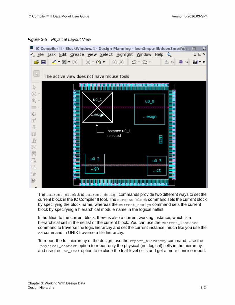
IC Compiler™ II Data Model User Guide L-2016.03-SP4IC Compiler™ II Data Model User Guide Version L-2016.03-SP4
Figure 3-5 Physical Layout View
The current_block and current_design commands provide two different ways to set the current block in the IC Compiler II tool. The current_block command sets the current block by specifying the block name, whereas the current_design command sets the current block by specifying a hierarchical module name in the logical netlist.
In addition to the current block, there is also a current working instance, which is a hierarchical cell in the netlist of the current block. You can use the current_instance command to traverse the logic hierarchy and set the current instance, much like you use the cd command in UNIX traverse a file hierarchy.
To report the full hierarchy of the design, use the report_hierarchy command. Use the -physical_context option to report only the physical (not logical) cells in the hierarchy, and use the -no_leaf option to exclude the leaf-level cells and get a more concise report.
Instance u0_1 selected
Chapter 3: Working With Design DataDesign Hierarchy 3-24

IC Compiler™ II Data Model User Guide Version L-2016.03-SP4
See Also
• current_block
• current_design
• current_instance
• report_hierarchy
• Hierarchical Query Using get_* Commands
current_block
The current_block command takes a block as an argument, such as an object returned by the get_blocks command. When the current_block command is used with an argument, it sets the current block to the specified block. When used without an argument, it returns the current block.
icc2_shell> current_block design3mp{mylibA:design3mp.design}
icc2_shell> current_block{mylibA:design3mp.design}
current_design
The current_design command takes a design object as an argument, such as an object returned by the get_designs command. In this context, a design is a hierarchical module in the logical netlist. When the current_design command is used with an argument, it sets the current block to the block containing the specified design. When used without an argument, it returns the current block, just like the current_block command.
icc2_shell> get_designs{design3mp mul32_infer0 design3s design3s_2 design3s_2 design3X}
icc2_shell> current_design design3X{mylibB:design3X.design}
icc2_shell> current_design{mylibB:design3X.design}
Chapter 3: Working With Design DataDesign Hierarchy 3-25Chapter 3: Working With Design DataDesign Hierarchy 3-25

IC Compiler™ II Data Model User Guide L-2016.03-SP4IC Compiler™ II Data Model User Guide Version L-2016.03-SP4
current_instance
The current working instance is a hierarchical cell in the logic netlist of the current block. The default current instance is the top-level cell of the current block. You can use the current_instance command to traverse the logic hierarchy and set the current instance much like you use the cd command in UNIX traverse a file hierarchy.
icc2_shell> current_block {mylibA:design3mp.design}
icc2_shell> current_instance Current instance is the top-level of design 'design3mp'
icc2_shell> get_cells -filter "is_hierarchical==true"{u0_0 u0_1 u0_2 u0_3 u_m u_p}
icc2_shell> current_instance u0_0u0_0icc2_shell> current_instance p0_iu0u0_0/p0_iu0icc2_shell> current_instance .u0_0/p0_iu0icc2_shell> current_instance ..u0_0icc2_shell> current_instance ../u0_1/p0_mul0u0_1/p0_mul0icc2_shell> current_instanceCurrent instance is the top-level of design 'design3mp'
report_hierarchy
The report_hierarchy command reports the hierarchy of a block. By default, it generates a report on the current block showing the full physical and logical reference hierarchy down to the leaf module level.
To get a more concise report, use the -physical_context option to report only the physical (not logical) cells in the hierarchy or the -no_leaf option to exclude the leaf-level cells, or both. For example,
icc2_shell> report_hierarchy -physical_context -no_leaf... mylibA:design3mp/fp.design design3s.nlib:design3s/fp.design mul32_infer0.nlib:mul32_infer0/fp.design design3s.nlib:design3s_2/fp.design design3s.nlib:design3s_3/fp.abstract 1
Chapter 3: Working With Design DataDesign Hierarchy 3-26

IC Compiler™ II Data Model User Guide Version L-2016.03-SP4
icc2_shell> report_hierarchy -physical_context...mylibA:design3mp/fp.design B4ISH1025_NS saed32io_wb D4I1025_NS saed32io_wb ISH1025_NS saed32io_wb ... design3s.nlib:design3s/fp.design AND2X1_RVT saed32rvt AND2X2_RVT saed32rvt AND3X1_RVT saed32rvt ... mul32_infer0:mul32_infer0/fp.design ... design3s.nlib:design3s_2/fp.design ISOLORX1_HVT saed32hvt LSDNSSX1_HVT saed32hvt_dlvl OAI222X1_RVT saed32rvt design3s.nlib:design3s_3/fp.abstract1
icc2_shell> report_hierarchy ...mylibA:design3mp/fp.design LSUPX1_HVT saed32hvt_ulvl NBUFFX16_LVT saed32lvt design3s.nlib:design3s/fp.design ISOLORAOX1_HVT saed32hvt SNPS_CLOCK_GATE_HIGH_div32_7 SNPS_CLOCK_GATE_HIGH_div32_8 ... (very long report shows all leaf-level logical and physical cells) ...
By default, multiple occurrences of a block or module are combined into a single report for all instances of the same block unless the occurrences are bound to different views. To expand the report to show the hierarchy of all instances, use the -hierarchical option of the command.
For more information, see the man page for the report_hierarchy command.
Hierarchical Query Using get_* Commands
The IC Compiler II tool offers commands to query the cells, nets, pins, and ports in the design database:
get_cellsget_netsget_pinsget_ports
Chapter 3: Working With Design DataDesign Hierarchy 3-27Chapter 3: Working With Design DataDesign Hierarchy 3-27

IC Compiler™ II Data Model User Guide L-2016.03-SP4IC Compiler™ II Data Model User Guide Version L-2016.03-SP4
Each command creates a collection of objects in the design that meet the criteria specified by the command options. You can use a collection as input to another command, or set a variable to the collection for future use.
The command options let you restrict the scope of the query by object name, hierarchical level, physical context, and object attributes. For example, for the get_cells command:
get_cells [patterns] [-hierarchial] [-physical_context] [-of_objects objects] [-filter expression] ... prompt> get_cells # get all cells at the current level of hierarchy prompt> get_cells * # get all cells at the current level of hierarchy prompt> get_cells BLKA/* # get all cells of BLKA prompt> get_cells R* \ # get cells named R* at -hierarchical # all levels of hierarchy prompt> get_cells R* \ # get cells named R* in the flat -physical_context # physical context prompt> get_cells \ # get all cells in the flat -physical_context \ # physical context that own -of_objects [get_nets n253] # physical pins of net n253 prompt> get_cells R* \ # get cells named R* at all levels -hierarchical \ # of hierarchy; include only the -filter defined(parent_block_cell) # blocks that have a parent # (only the cells of subblocks)
Query Using Only a Search String
When you query the design for objects using only a search string and no other options, the command searches for objects that have the specified name. The name string can be plain or hierarchical:
prompt> get_cells R* # get cells named R* at current level
prompt> get_cells REG1/R* # get cells named REG1/R* # (same as cells named R* in REG1)
The asterisk wildcard character (*) does not match with the hierarchy separator character, the forward slash (/). Therefore, a search string without any forward slash characters occurs only at the current level and does not traverse the hierarchy.
Chapter 3: Working With Design DataDesign Hierarchy 3-28

IC Compiler™ II Data Model User Guide Version L-2016.03-SP4
Note that the slash character is sometimes used as part of a cell name and not as a hierarchy separator, as demonstrated in the following example.
prompt> get_cells I_P{I_P} prompt> get_cells I_P* # "*" does not match hierarchy separator,{I_P} # search current level only prompt> get_cells I_P/*U3 # search under cell I_P, one level only {I_P/U3 I_P/m2/U3}
Why did the last search return I_P/m2/U3, which appears to be two levels below I_P? The answer is that the cell is directly under I_P and is literally named “m2/U3” with the slash character inside the cell name. You can confirm this by querying the cell attributes:
prompt> get_attribute [get_cells I_P/*U3] -name parent_cell{I_P I_P}
prompt> get_attribute [get_cells I_P/*U3] -name nameU3 m2/U3
Query With the -hierarchical Option
When you query the design for objects with the -hierarchical option, the command searches for objects throughout the logical hierarchy of the design:
prompt> get_cells R* -hierarchical {BLK1/REG43 BLK2/RXF38 BLK2/ACE1/RG95}
The command searches for an object of the exact name at each level of hierarchy, like the find command under UNIX. Therefore, the search string must be a simple name; it cannot use hierarchy separator characters:
prompt> get_cells BLK1/R* -hierarchical Warning: No cell objects matched 'BLK1/R*' (SEL-004)Error: Nothing matched for collection (SEL-005)
If you include a slash character in the search string while using the -hierarchical option, the command searches for objects that literally have the slash character as part of the object name; it does not search a lower level of hierarchy.
Query With the -physical_context Option
When you query the design for objects with the -physical_context option, the command searches for objects in the flattened physical netlist for the design:
prompt> get_cells *RLB_27 -physical_context {I_BLK1/I_REG19/RLB_27}
Chapter 3: Working With Design DataDesign Hierarchy 3-29Chapter 3: Working With Design DataDesign Hierarchy 3-29

IC Compiler™ II Data Model User Guide L-2016.03-SP4IC Compiler™ II Data Model User Guide Version L-2016.03-SP4
Note that an asterisk wildcard character (*) in a search string matches with the forward slash character, interpreting the slash as part of the object name.
In the flattened physical netlist, all cells are considered leaf cells. This is the netlist seen by the router. The full names of the cells can contain slash characters that reflect the hierarchy of the design, but the physical netlist itself is treated as entirely flat and the slash characters are treated as ordinary characters used in object names.
Because the netlist is considered flat, it is not necessary (and not recommended) to use the -hierarchical option together with the -physical_context option.
Query With the -of_objects Option
When you query the design for objects with the -of_objects option, the command searches for objects that are associated with the listed objects:
prompt> get_cells I_P/* # get cells{I_P/U11 I_P/U13 I_P/U161 I_P/U14} prompt> get_pins -of_objects [get_cells I_P/U13] # get pins of cell{I_P/U13/A1 I_P/U13/A2 I_P/U13/Y I_P/U13/VDD I_P/U13/VSS}
prompt> get_nets -of_objects [get_cells I_P/U13] # get nets connected{I_P/n287 I_P/n17 I_P/n26 I_P/VDD I_P/VSS} # to cell
prompt> get_cells -of_objects [get_nets I_P/n17] # get cells connected{I_P/U161 I_P/U14 I_P/m2/U13} # to net
You cannot specify a search string while also using the -of_objects option, but you can filter the results with the -filter option.
Query With the -filter Option
In a get_* command, you can use the -filter option to restrict the generated collection to only the objects that meet some filtering condition specified as a Boolean expression.
For example, the following command gets all cells named B* but then only allows the cells that have their ref_name attribute set to the string FD2 to be added to the collection:
prompt> get_cells "B*" -filter "ref_name == FD2"{"B_reg1", "B_reg2", "B_reg3", "B_reg4"}
The following hierarchy-related attributes can help you find the logical or physical owner of an object:
• parent_cell – The logical cell that contains the object. For a physical object, this is the cell of the parent block. For a purely logical object, this is different from the cell of the parent block.
Chapter 3: Working With Design DataDesign Hierarchy 3-30

IC Compiler™ II Data Model User Guide Version L-2016.03-SP4
• parent_block – The physical block (libname:block/label.design) that contains the object. The parent block of a block is the same block itself.
• parent_block_cell – The first cell that is a block (libname:block/label.design) found while traversing the parent cells up the hierarchy. When the object is associated with a logic hierarchy, the result is different from the parent cell.
• top_block – The top-level block (libname:block/label.design) in the current block hierarchy.
For example,
prompt> get_cells -hierarchical # get objects in all levels of # hierarchy, both logical and physical # To create a collection of physical cells in a subblockprompt> get_cells –physical_context \ # get physical cells of object –of_objects subblock1 # named "subclock1" prompt> get_cells -hierarchical \ # get objects from the top level –filter undefined(parent_block_cell) # (those that have no parent) prompt> get_cells -hierarchical \ # get cells inside all subblocks –filter defined(parent_block_cell) # (those that have a parent)
Technology Data Access
You can get, report, and modify the library’s technology data using Tcl commands. This is the data specified in a technology file and read into the library by the read_tech_file command or by using the -technology option of the create_lib command.
To query or modify the technology data for a library, use the object types listed in the following table.
Chapter 3: Working With Design DataTechnology Data Access 3-31Chapter 3: Working With Design DataTechnology Data Access 3-31

IC Compiler™ II Data Model User Guide L-2016.03-SP4IC Compiler™ II Data Model User Guide Version L-2016.03-SP4
The following session example shows how to query and modify the unit tile data in the library’s technology.
icc2_shell> list_attributes -application -class site_def...Attribute Name Object Type Properties ...---------------------------------------------------------full_name site_def string A,S height site_def distance A,S is_default site_def boolean A,S symmetry site_def string A,S... icc2_shell> report_site_defs ... Width Height Type Is_default Tech Symmetry Legal_orienta-------------------------------------------------------------------------unit1 0.15 1.67 core default saed32 -- R0
Table 3-3 Technology Objects and Access Commands
Object name Tech file section Object access commands
tech Technology get_techs
create_tech
report_attributes -application [get_techs]
remove_tech
site_def Tile get_site_defs
create_site_def
report_site_defs
layer Layer get_layers
create_layer
report_attributes -application [get_layers]
via_def ContactCode get_via_defs
create_via_def
report_via_defs
density_rule DensityRule get_density_rules
create_density_rule
report_attributes -appl [get_density_rules]
remove_density_rules
Chapter 3: Working With Design DataTechnology Data Access 3-32

IC Compiler™ II Data Model User Guide Version L-2016.03-SP4
icc2_shell> report_attributes -application -class site_def \ [get_site_defs]...Design Object Type Attribute Name Value--------------------------------------------------------------design3mp unit1 string full_name unit1 design3mp unit1 distance height 1.6720 design3mp unit1 boolean is_default true design3mp unit1 string symmetry ...icc2_shell> set_attribute -objects [get_site_defs] -name symmetry \ -value {Y}{unit}icc2_shell> get_attribute -objects [get_site_defs] -name symmetryYicc2_shell> create_site_def -name unit2 -width 0.1520 \ -height 3.3440 -symmetry Y {unit2}icc2_shell> get_site_defs{unit1 unit2}icc2_shell> report_attributes -application -class site_def \ [get_site_defs unit2]...Design Object Type Attribute Name Value----------------------------------------------------------------design3mp unit1 string full_name unit2 design3mp unit1 distance height 3.3440 design3mp unit1 boolean is_default false design3mp unit1 string symmetry Y...
If you make technology changes, do so before you load any block data. The technology changes are saved in the library and remain in effect from session to session.
You can use the write_tech_file command to write out the modified technology data into a technology file. However, the technology file syntax does not support the symmetry and is_default attributes of site_def objects or the routing_direction and track_offset attributes of layer objects, so these attributes are not written to the technology file. For more information on preparing the site definition and routing layer technology data, see “Completing the Technology Data” in the IC Compiler II Library Preparation User Guide.
You can use the create_routing_rule command to create nondefault routing rules and the set_routing_rule command to apply these rules to specific layers or nets. These nondefault routing rules do not change the default rules defined in the technology file and are not written out by the write_tech_file command.
Chapter 3: Working With Design DataTechnology Data Access 3-33Chapter 3: Working With Design DataTechnology Data Access 3-33

IC Compiler™ II Data Model User Guide L-2016.03-SP4IC Compiler™ II Data Model User Guide Version L-2016.03-SP4
Reporting Design Information
A block is a container for physical and functional design data. The current block is the default block affected by block-related commands. You can set or report the current block by using the current_block command or set the current block for a specified top-level module by using the current_design command.
To report information about the design data stored in the current block, use the following commands:
• report_design
By default, using the report_design command without options generates a summary report on the design contents such as the number of cells, hierarchical levels, chip area, and total route length. For details, see Reporting Design Information With the report_design Command.
• check_physical_constraints
The command checks the design for issues related to physical constraints that could lead to problems at later stages of the design flow, and reports these issues as error, warning, and information messages. The checked conditions include basic floorplan data, site rows, move bounds, group bounds, layers, tracks, macros, other cell instances, and placement blockages. For details, see Reporting Physical Constraints With the check_physical_constraints Command.
Reporting Design Information With the report_design Command
By default, using the report_design command without options generates a summary report on the design contents such as the number of cells, hierarchical levels, chip area, and total route length. For a more detailed report, specify the report type in the command:
icc2_shell> report_design -library...icc2_shell> report_design -netlist...icc2_shell> report_design -netlist -hierarchical...icc2_shell> report_design -floorplan...icc2_shell> report_design -routing...
The report_design command generates a detailed report as shown in the following example:
icc2_shell> report_design -netlist...
Chapter 3: Working With Design DataReporting Design Information 3-34

IC Compiler™ II Data Model User Guide Version L-2016.03-SP4
------------------------------------------------------------------------ NETLIST INFORMATION ------------------------------------------------------------------------CELL INSTANCE INFORMATION------------------------------------------------------------------------Cell Instance Type Count % of Area % of siteAreaPerSite total total ------------------------------------------------------------------------TOTAL LEAF CELLS 12973 100 9360583.005 100 unit:36911736 Standard cells 12704 97 61696.760 0 unit:242763 Filler cells 0 0 0.000 0 Diode cells 0 0 0.000 0 Module cells 4 0 6117000.323 65 unit:24069033 Soft macro cells 4 0 6117000.323 65 unit:24069033 Hard macro cells 4 0 49885.923 0 unit:197220 ...
REFERENCE DESIGN INFORMATION------------------------------------------------------------------------Number of reference designs used:88 ------------------------------------------------------------------------Name Type Count Width Height Area ------------------------------------------------------------------------SDFFX1_RVT lib_cell 1729 5.17 1.67 8.641 ...NBUFFX32_RVT lib_cell 1727 6.38 1.67 10.674 ...AO22X1_RVT lib_cell 1364 1.52 1.67 2.541 ......
NET INFORMATION------------------------------------------------------------------NetType Count FloatingNets Vias Nets/Cells------------------------------------------------------------------Total 59276 45346 113837 4.569Signal 59276 45346 113837 4.569Power 0 0 0 0.000...
NET FANOUT AND PIN COUNT INFORMATION---------------------------------------------------Fanout Netcount netPinCount NetCount---------------------------------------------------<2 54241 <2 453462 2452 2 91233 979 3 22244 559 4 9795 243 5 559...
PORT AND PIN INFORMATION-----------------------------------------------------------------Type Total Input Output Inout 3-st ...-----------------------------------------------------------------Total 103285 86052 18407 1272 484 ...
Chapter 3: Working With Design DataReporting Design Information 3-35Chapter 3: Working With Design DataReporting Design Information 3-35

IC Compiler™ II Data Model User Guide L-2016.03-SP4IC Compiler™ II Data Model User Guide Version L-2016.03-SP4
Macro 600 344 256 0 256 ...Ports 261 160 228 127 0 ......
For more information about the report_design command, see the man page. Additional usage information is available in the IC Compiler II Implementation User Guide and IC Compiler II Design Planning User Guide.
Reporting Physical Constraints With the check_physical_constraints Command
You can check a design’s physical constraints by using the check_physical_constraints command. The command checks the design for issues related to physical constraints that could lead to problems at later stages of the design flow, and reports these issues as error, warning, and information messages.
The checked conditions include
• Basic floorplan data
• Site rows
• Move bounds
• Group bounds
• Layers
• Tracks
• Macros and other cell instances
• Placement blockages
To check the physical constraints of the design, run the check_physical_constraints command:
icc2_shell> check_physical_constraints...Warning: The spacing of layer 'VTL_N' is greater than the difference of the pitch and width of the layer. (DCHK-105)Warning: The spacing of layer 'PO' is greater than the difference of the pitch and width of the layer. (DCHK-105)Information: The layer 'M8' does not contain any PG shapes. (DCHK-104)Information: The layer 'M9' does not contain any PG shapes. (DCHK-104)Warning: The orientation of cell instance 'tapfiller_TAPCELLBWP16P90_0' does not match any legal orientations. (DCHK-103)Warning: The orientation of cell instance 'tapfiller_TAPCELLBWP16P90_1' does not match any legal orientations. (DCHK-103)
Chapter 3: Working With Design DataReporting Design Information 3-36

IC Compiler™ II Data Model User Guide Version L-2016.03-SP4
1
For information about the issues the tool identifies and how to fix them, see the man page for the corresponding message ID number.
In addition to generating a report, the check_physical_constraints command generates an enhanced messaging system (EMS) database that you can view by using the message browser in the IC Compiler II GUI. Create the EMS database by running the create_ems_database command before you run the check_physical_constraints command:
icc2_shell> create_ems_database check_hier.emsicc2_shell> check_physical_constraintsicc2_shell> save_ems_database
In the IC Compiler II GUI message browser, you can sort, filter, and link the messages to the corresponding man page. For information about viewing the EMS database in the message browser, see the IC Compiler II Implementation User Guide.
Polygon Manipulation
To create and edit polygon shapes, you can use two kinds of abstract geometric objects:
• poly_rect – a single geometric shape that consists of a set of coordinate points
• geo_mask – a collection of poly_rect objects
The poly_rect and geo_mask type objects are abstract and have no direct functional purpose in a block. To create a functional shape such as a mask layer, blockage, or keepout region, you need to convert poly_rect or geo_mask objects into real objects.
The following figure shows the flow to create, edit, and convert abstract shapes to make real shapes.
Chapter 3: Working With Design DataPolygon Manipulation 3-37Chapter 3: Working With Design DataPolygon Manipulation 3-37

IC Compiler™ II Data Model User Guide L-2016.03-SP4IC Compiler™ II Data Model User Guide Version L-2016.03-SP4
Figure 3-6 How to Manipulate Geometric Objects
The commands in the following table are available to create, manipulate, and convert polygon shapes.
Table 3-4 Polygon Manipulation Commands
Command Description
compute_area Calculates the area of a geometric region
compute_polygons Performs a Boolean operation between two shapes to create a geo_mask object
copy_to_layer Copies a geo_mask object to create a collection of shapes in a mask layer
create_geo_mask Copies geometric objects to create a new geo_mask object
create_poly_rect Creates a collection of poly_rect objects from a list of coordinates and optionally associates a layer with the result
resize_polygons Pushes the edges of specified polygons inward or outward, creating a new geo_mask object
split_polygons Decomposes a geometric region into rectangles or trapezoids, creating a collection of geo_mask or poly_rect objects
poly_rect object
geo_mask object
create_poly_rect
coordinate list
Existing real geometric objects: shape, layer, cell, voltage area, placement bound ...
create_geo_maskcompute_polygonsresize_polygonsExisting
geo_mask object
copy_to_layer
layer object
foreach_in_collection ... ... create_shape ...
New geometric objects: shape, layer, voltage area, placement bound ...
Manipulate shapes
coordinate list
Chapter 3: Working With Design DataPolygon Manipulation 3-38

IC Compiler™ II Data Model User Guide Version L-2016.03-SP4
For details, see
• Creating poly_rect and geo_mask Objects
• Converting geo_mask Objects Into Functional Shapes
Creating poly_rect and geo_mask Objects
To create a poly_rect object, use the create_poly_rect command and specify the vertex coordinates: two points for a rectangle or three or more points for a polygon of any shape.
To create a geo_mask object, you can copy existing geometric shapes with the create_geo_mask command or perform operations on existing shapes with the compute_polygons or resize_polygons command.
In the following example, you create two overlapping rectangular poly_rect objects, perform a logical OR of these shapes to create a new geo_mask object, and copy the geo_mask object to create a rectilinear shape on the M2 layer.
Figure 3-7 Creating a geo_mask Object From Two poly_rect Objects
icc2_shell> current_block{libA:block1.design}icc2_shell> set myshape1 [create_poly_rect -boundary {{10 10} {30 20}}]{{{10 10} {30 20}}}icc2_shell> set myshape2 [create_poly_rect -boundary {{15 15} {20 30}}]{{{15 15} {20 40}}}icc2_shell> set my_gm1 [compute_polygons \ -objects1 $myshape1 -objects2 $myshape2 -operation OR]...
poly_rect “myshape1”
poly_rect“myshape2”
geo_mask “my_gm1” = logical OR of myshape1, myshape2
(10,10)
(30,20)
(15,15)
(20,30)
Chapter 3: Working With Design DataPolygon Manipulation 3-39Chapter 3: Working With Design DataPolygon Manipulation 3-39

IC Compiler™ II Data Model User Guide L-2016.03-SP4IC Compiler™ II Data Model User Guide Version L-2016.03-SP4
icc2_shell> report_attributes -application -class geo_mask $my_gm1...Design Object Type Attribute Name Value-----------------------------------------------------------------------block1 geo_mask boolean is_empty falseblock1 geo_mask string object_class geo_maskblock1 geo_mask collection poly_rects {20 40} ...block1 geo_mask int shape_count 11icc2_shell> copy_to_layer -layer M2 -geo_masks $my_gm1{POLYGON_13_0}icc2_shell> save_block...
These commands create a rectilinear shape on the M2 layer, which you can display in the GUI as shown in the following figure.
Figure 3-8 geo_mask Object Copied to M2 Layer Shape
Alternatively, you can use the compute_polygons command directly with coordinate lists:
icc2_shell> set my_gm1 [compute_polygons \ -objects1 {{10 10} {30 20}} -objects2 {{15 15} {20 30}} -operation OR]...icc2_shell> copy_to_layer -layer M2 -geo_masks $my_gm1{POLYGON_13_0}
Another polygon manipulation command is the resize_polygons command, which pushes the edges of specified polygons inward or outward, creating a new geo_mask object. For example, the following script takes the existing shapes on the M2 layer, pushes the edges inward by 1.0 unit to make a new geo_mask object, and then converts the geo_mask object into a new shape on the VIA2 layer.
set sh2 [get_shapes -of_objects M2] set gm2 [resize_polygons -objects $sh2 -size -1] copy_to_layer -layer VIA2 -geo_masks $gm2
Chapter 3: Working With Design DataPolygon Manipulation 3-40

IC Compiler™ II Data Model User Guide Version L-2016.03-SP4
Figure 3-9 M3 Layer Shape Created by Resizing
See Also
• Polygon Manipulation
• Converting geo_mask Objects Into Functional Shapes
Converting geo_mask Objects Into Functional Shapes
The poly_rect and geo_mask type objects are abstract and have no direct functional purpose in a block. To create a functional shape such as a mask layer, blockage, or keepout region, you need to convert poly_rect or geo_mask objects into real objects by using a command such as copy_to_layer, create_placement_blockage, or create_shape.
The following example creates a geo_mask object and copies it to a shape on the M2 layer.
icc2_shell> set pr2 [create_poly_rect -boundary {{10 10} {20 30}}]...icc2_shell> set gm2 [create_geo_mask -objects $pr2]...icc2_shell> copy_to_layer -layer M2 -geo_masks $gm2{RECT_13_0}
A geo_mask object is a collection of poly_rect objects. If the geo_mask object contains multiple distinct shapes, you can iterate through the collection by using the foreach_in_collection command, and convert each poly_rect object to a real object.
For example, the following script creates a geo_mask object named GEO_COL, which contains a set of shapes generated by the overlap of cell U3 with all shapes on layer M2. The script then iterates through the GEO_COL collection and converts each shape to a new shape on the M3 layer, as shown in Figure 3-10.
Chapter 3: Working With Design DataPolygon Manipulation 3-41Chapter 3: Working With Design DataPolygon Manipulation 3-41
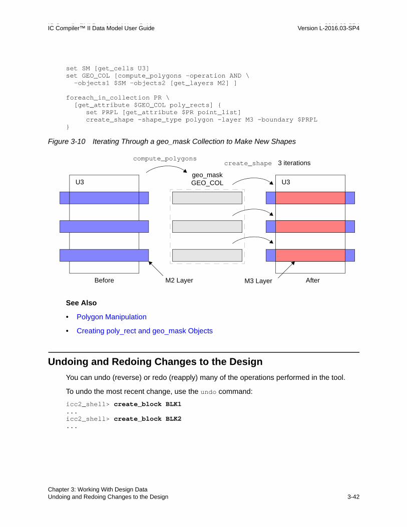
IC Compiler™ II Data Model User Guide L-2016.03-SP4IC Compiler™ II Data Model User Guide Version L-2016.03-SP4
set SM [get_cells U3]set GEO_COL [compute_polygons –operation AND \ -objects1 $SM -objects2 [get_layers M2] ]
foreach_in_collection PR \ [get_attribute $GEO_COL poly_rects] { set PRPL [get_attribute $PR point_list] create_shape –shape_type polygon -layer M3 -boundary $PRPL}
Figure 3-10 Iterating Through a geo_mask Collection to Make New Shapes
See Also
• Polygon Manipulation
• Creating poly_rect and geo_mask Objects
Undoing and Redoing Changes to the Design
You can undo (reverse) or redo (reapply) many of the operations performed in the tool.
To undo the most recent change, use the undo command:
icc2_shell> create_block BLK1...icc2_shell> create_block BLK2...
U3 U3geo_mask GEO_COL
M2 Layer M3 Layer
compute_polygonscreate_shape
Before After
3 iterations
Chapter 3: Working With Design DataUndoing and Redoing Changes to the Design 3-42
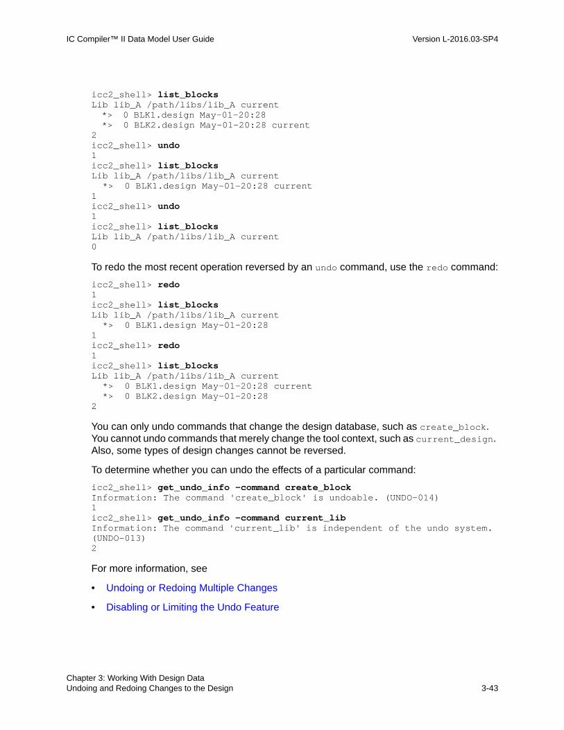
IC Compiler™ II Data Model User Guide Version L-2016.03-SP4
icc2_shell> list_blocksLib lib_A /path/libs/lib_A current *> 0 BLK1.design May-01-20:28 *> 0 BLK2.design May-01-20:28 current 2 icc2_shell> undo1 icc2_shell> list_blocksLib lib_A /path/libs/lib_A current *> 0 BLK1.design May-01-20:28 current1icc2_shell> undo1icc2_shell> list_blocksLib lib_A /path/libs/lib_A current0
To redo the most recent operation reversed by an undo command, use the redo command:
icc2_shell> redo1icc2_shell> list_blocksLib lib_A /path/libs/lib_A current *> 0 BLK1.design May-01-20:281icc2_shell> redo1icc2_shell> list_blocksLib lib_A /path/libs/lib_A current *> 0 BLK1.design May-01-20:28 current *> 0 BLK2.design May-01-20:282
You can only undo commands that change the design database, such as create_block. You cannot undo commands that merely change the tool context, such as current_design. Also, some types of design changes cannot be reversed.
To determine whether you can undo the effects of a particular command:
icc2_shell> get_undo_info -command create_blockInformation: The command 'create_block' is undoable. (UNDO-014)1icc2_shell> get_undo_info -command current_libInformation: The command 'current_lib' is independent of the undo system. (UNDO-013)2
For more information, see
• Undoing or Redoing Multiple Changes
• Disabling or Limiting the Undo Feature
Chapter 3: Working With Design DataUndoing and Redoing Changes to the Design 3-43Chapter 3: Working With Design DataUndoing and Redoing Changes to the Design 3-43

IC Compiler™ II Data Model User Guide L-2016.03-SP4IC Compiler™ II Data Model User Guide Version L-2016.03-SP4
Undoing or Redoing Multiple Changes
To undo or redo multiple changes in a single command, use the -levels option:
icc2_shell> undo -levels 3 # Reverse the 3 most recent changes3
icc2_shell> redo -levels 2 # Reapply the 2 most recent reversed changes2
To redo all recent changes and restore the design to the most recent available state:
icc2_shell> redo -all 5
The number returned by this command (5 in this example) indicates the number of changes redone.
The tool maintains an internal undo list to keep track of the most recent design changes that can be reversed. If you plan to make multiple changes that you might want to undo later, you can set an undo marker in the list, and later undo all of changes back to the point at which you set the marker:
icc2_shell> create_block block1...icc2_shell> create_undo_marker my_marker...icc2_shell> create_block block2...icc2_shell> create_block block3...icc2_shell> undo -marker my_marker2icc2_shell> list_blocksLib lib_B /path/libs/lib_B current *> 0 block1.design May-02-21:08 current1
Conversely, if you plan to undo multiple recent changes that you might want to redo later, you can set an undo marker, and later redo all of the changes forward to the point at which you set the marker:
icc2_shell> create_block block1...icc2_shell> create_block block2...icc2_shell> create_block block3...icc2_shell> create_undo_marker mrkA...icc2_shell> undo...
Chapter 3: Working With Design DataUndoing and Redoing Changes to the Design 3-44

IC Compiler™ II Data Model User Guide Version L-2016.03-SP4
icc2_shell> undo...icc2_shell> list_blocksLib lib_A /path/libs/lib_A current *> 0 block1.design May-02-21:18 current1icc2_shell> redo -marker mrkA2icc2_shell> list_blocksLib lib_A /path/libs/lib_A current *> 0 block1.design May-02-21:18 current *> 0 block2.design May-02-21:18 *> 0 block3.design May-02-21:183
Note: If you run a command that is not reversible, the tool clears the undo list and you can no longer reverse previous operations.
To get information about the current undo list:
icc2_shell> get_undo_infois_enabled true is_undoable true undo_cmd_name "create_block" is_redoable false redo_cmd_name "" depth 4 max_depth 100 memory 104747 max_memory 1000000000
Disabling or Limiting the Undo Feature
The undo feature uses runtime and memory to maintain the design history. If you do not need this feature, you can disable it:
icc2_shell> set_app_options -name shell.undo.enabled falseshell.undo.enabled false
To disable the undo feature for one or more commands or to execute a block of commands as a single “undoable” unit, use the eval_with_undo command.
By default, the tool stores no more than 100 changes and uses no more than 1GB of memory to maintain the history of changes for the undo command. You can optionally decrease these limits to reduce runtime and memory usage:
icc2_shell> set_app_options -name shell.undo.max_levels -value 50shell.undo.max_levels 50icc2_shell> set_app_options -name shell.undo.max_memory -value 500000000shell.undo.max_memory 500000000
Conversely, you can increase these limits to handle a larger undo history.
Chapter 3: Working With Design DataUndoing and Redoing Changes to the Design 3-45Chapter 3: Working With Design DataUndoing and Redoing Changes to the Design 3-45

IC Compiler™ II Data Model User Guide L-2016.03-SP4IC Compiler™ II Data Model User Guide Version L-2016.03-SP4
Schema Versions
The IC Compiler II database infrastructure is periodically updated to support new database features. Each new version of the database is called a “schema” and each schema has a version number. When you save a library with the save_lib command, the library information is stored under the tool’s current schema.
To get a report of tool and schema version numbers and tool compatibility, use the report_versions command:
icc2_shell> report_versions J-2014.06 ICC2 schema revision: 1.0...
L-2016.03 ICC2 schema revision: 1.165 Compatibility: - ICV K-2015.12-SP2 - PrimeRail K-2015.12-SP2
Includes Support for: - Conn view for rail analysis...
To determine the schema number of a library, open the library and use the get_attribute command to report the library’s read_from_schema_version attribute:
icc2_shell> get_attribute -objects [current_lib] \ -name read_from_schema_version1.165icc2_shell> get_attribute -objects [get_libs tech32hvt] \ -name read_from_schema_version1.063
A schema number such as “1.165” consists of a major version number before the decimal point (“1”) and a minor version number after the decimal point (“165”).
IC Compiler II tools are backward-compatible, but not directly forward-compatible. In other words, you can read in an older library with a newer tool, which updates the library from the older schema to the current one. However, you cannot always directly read a newer library with an older tool.
Service pack releases of the tools (such as L-2016.03-SP2) are generally both forward and backward compatible with each other and with the baseline release (such as L-2016.03).
Chapter 3: Working With Design DataSchema Versions 3-46

IC Compiler™ II Data Model User Guide Version L-2016.03-SP4
When you save a library, the tool saves it under the current schema by default. To make a newer library compatible with an older tool, open the library in the newer tool and then save it under a new name by using the save_lib command with the -version option:
icc2_shell> current_lib{my_lib}icc2_shell> save_lib -as my_lib2 -version K-2015.06...
Then the new library can be opened by the older tool, as shown in the following figure.
Figure 3-11 IC Compiler II Database Schema Compatibility
If your newer library has many blocks but you only need a few blocks in the older format, to reduce the conversion time and save disk space, copy the few needed blocks into a separate new library, and then save the smaller library in the older format.
Automatic conversion
Design libraryschema 1.165
Design libraryschema 1.110
K-2015.06tool
L-2016.03 tool
save_lib -as my_lib2 \ -version K-2015.06
Chapter 3: Working With Design DataSchema Versions 3-47Chapter 3: Working With Design DataSchema Versions 3-47

IC Compiler™ II Data Model User Guide L-2016.03-SP4IC Compiler™ II Data Model User Guide Version L-2016.03-SP4
Chapter 3: Working With Design DataSchema Versions 3-48
![Compiler Construction - Lecture : [1ex] Summer Semester ...(as opposed to rewriting the whole compiler) Fast compiler implementation:generating IC much easier than generating MC Code](https://img.pdfslide.us/doc/110x75/5ecccf8bc221095fc21e2bd6/compiler-construction-lecture-1ex-summer-semester-as-opposed-to-rewriting.jpg)