Embed Size (px)
Citation preview
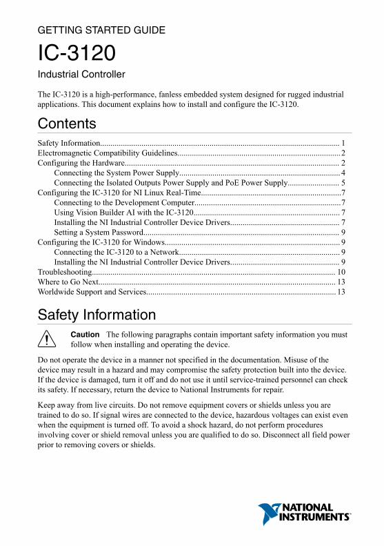
GETTING STARTED GUIDE
IC-3120Industrial Controller
The IC-3120 is a high-performance, fanless embedded system designed for rugged industrialapplications. This document explains how to install and configure the IC-3120.
ContentsSafety Information.................................................................................................................... 1Electromagnetic Compatibility Guidelines...............................................................................2Configuring the Hardware........................................................................................................ 2
Connecting the System Power Supply.............................................................................. 4Connecting the Isolated Outputs Power Supply and PoE Power Supply......................... 5
Configuring the IC-3120 for NI Linux Real-Time....................................................................7Connecting to the Development Computer.......................................................................7Using Vision Builder AI with the IC-3120....................................................................... 7Installing the NI Industrial Controller Device Drivers..................................................... 7Setting a System Password............................................................................................... 9
Configuring the IC-3120 for Windows..................................................................................... 9Connecting the IC-3120 to a Network.............................................................................. 9Installing the NI Industrial Controller Device Drivers..................................................... 9
Troubleshooting...................................................................................................................... 10Where to Go Next................................................................................................................... 13Worldwide Support and Services............................................................................................ 13
Safety InformationCaution The following paragraphs contain important safety information you mustfollow when installing and operating the device.
Do not operate the device in a manner not specified in the documentation. Misuse of thedevice may result in a hazard and may compromise the safety protection built into the device.If the device is damaged, turn it off and do not use it until service-trained personnel can checkits safety. If necessary, return the device to National Instruments for repair.
Keep away from live circuits. Do not remove equipment covers or shields unless you aretrained to do so. If signal wires are connected to the device, hazardous voltages can exist evenwhen the equipment is turned off. To avoid a shock hazard, do not perform proceduresinvolving cover or shield removal unless you are qualified to do so. Disconnect all field powerprior to removing covers or shields.

Because of the danger of introducing additional hazards, do not install unauthorized parts ormodify the device. Use the device only with the chassis, modules, accessories, and cablesspecified in the installation instructions. All covers and filler panels must be installed whileoperating the device.
This is a Pollution Degree 2 device. Do not operate the device in an explosive atmosphere orwhere flammable gases or fumes may be present. Operate the device only at or below thepollution degree stated in the specifications. Pollution consists of any foreign matter—solid,liquid, or gas—that may reduce dielectric strength or surface resistivity. The following is adescription of pollution degrees.• Pollution Degree 1—No pollution or only dry, nonconductive pollution occurs. The
pollution has no effect.• Pollution Degree 2—Normally only nonconductive pollution occurs. Occasionally,
nonconductive pollution becomes conductive because of condensation.• Pollution Degree 3—Conductive pollution or dry, nonconductive pollution occurs.
Nonconductive pollution becomes conductive because of condensation.
Clean the device and accessories by brushing off light dust with a soft, nonmetallic brush.Remove other contaminants with a stiff, nonmetallic brush. The unit must be completely dryand free from contaminants before returning it to service.
You must insulate signal connections for the maximum voltage for which the device is rated.Do not exceed the maximum ratings for the device. Remove power from signal lines beforeconnection to or disconnection from the device.
Electromagnetic Compatibility GuidelinesThis product was tested and complies with the regulatory requirements and limits forelectromagnetic compatibility (EMC) stated in the product specifications. These requirementsand limits provide reasonable protection against harmful interference when the product isoperated in the intended operational electromagnetic environment.
This product is intended for use in industrial locations. However, harmful interference mayoccur in some installations, when the product is connected to a peripheral device or test object,or if the product is used in residential or commercial areas. To minimize interference withradio and television reception and prevent unacceptable performance degradation, install anduse this product in strict accordance with the instructions in the product documentation.
Furthermore, any changes or modifications to the product not expressly approved by NationalInstruments could void your authority to operate it under your local regulatory rules.
Configuring the HardwareRemove the IC-3120 from the package and inspect the system for damage. Notify NationalInstruments if the system appears damaged in any way. Do not use a damaged system.
2 | ni.com | IC-3120 Getting Started Guide
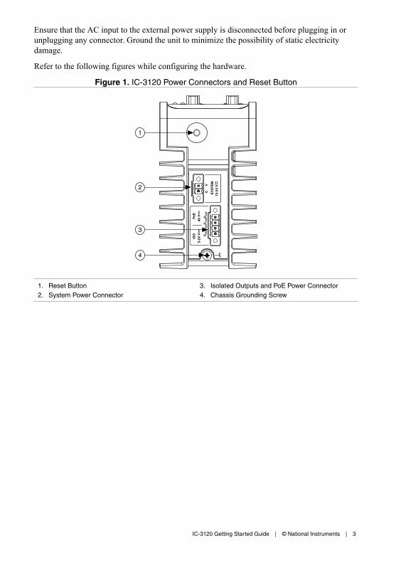
Ensure that the AC input to the external power supply is disconnected before plugging in orunplugging any connector. Ground the unit to minimize the possibility of static electricitydamage.
Refer to the following figures while configuring the hardware.
Figure 1. IC-3120 Power Connectors and Reset Button
SY
ST
EM
Po
E
48 V
ISO C
ISO
CP
oEV
Po
EV
ISO
5-24
V
12-2
4 V
C
V2
3
1
4
1. Reset Button2. System Power Connector
3. Isolated Outputs and PoE Power Connector4. Chassis Grounding Screw
IC-3120 Getting Started Guide | © National Instruments | 3
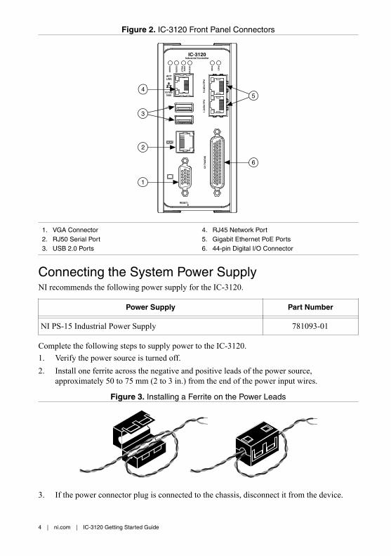
Figure 2. IC-3120 Front Panel Connectors
RESET
DIG
ITAL
I/O
10/100/1000
ACT/LINK
US
ER
1
US
ER
2
PW
R/
FAU
LT
STA
TU
S
Po
E0
Po
E P
OR
T 0
Po
E P
OR
T 1
Po
E1
5
3
6
1
2
4
IC-3120Industrial Controller
1. VGA Connector2. RJ50 Serial Port3. USB 2.0 Ports
4. RJ45 Network Port5. Gigabit Ethernet PoE Ports6. 44-pin Digital I/O Connector
Connecting the System Power SupplyNI recommends the following power supply for the IC-3120.
Power Supply Part Number
NI PS-15 Industrial Power Supply 781093-01
Complete the following steps to supply power to the IC-3120.1. Verify the power source is turned off.2. Install one ferrite across the negative and positive leads of the power source,
approximately 50 to 75 mm (2 to 3 in.) from the end of the power input wires.
Figure 3. Installing a Ferrite on the Power Leads
3. If the power connector plug is connected to the chassis, disconnect it from the device.
4 | ni.com | IC-3120 Getting Started Guide

Figure 4. 2-Position Power Screw Terminal Connector
1
23
1. V (Positive) Terminal Screw2. C (Negative) Terminal Screw3. Connector Screws
Caution Do not tighten or loosen the terminal screws on the power connectorwhile the power is on.
4. Connect the positive lead of the power source to the V terminal of the power connectorplug and tighten the terminal screw to 0.2 to 0.25 N · m (1.8 to 2.2 lb · in.) of torque.
5. Connect the negative lead of the power source to the C terminal of the power connectorplug and tighten the terminal screw to 0.2 to 0.25 N · m (1.8 to 2.2 lb · in.) of torque.
6. Install the power connector plug into the SYSTEM power receptacle on the IC-3120chassis and tighten the connector screws to 0.4 N · m (3.5 lb · in.) of torque.
7. Turn on the external power source.
Connecting the Isolated Outputs Power Supply andPoE Power SupplyNI recommends the following power supplies for the IC-3120.
Power Supply Part Number
NI PS-15 Industrial Power Supply, to power the isolated outputs 781093-01
48 V, DIN Rail, Industrial Power Supply for Power over Ethernet 783307-01
48 V, Desktop Power Supply for Power over Ethernet 783308-01
Complete the following steps to supply power to the PoE ports and the isolated outputs.1. Verify the power source is turned off.2. Install one ferrite across the negative and positive leads of the power sources,
approximately 50 to 75 mm (2 to 3 in.) from the end of the power input wires. If you areusing an isolated output power supply and a PoE power supply, wrap the wires for bothpower supplies through the same ferrite.
IC-3120 Getting Started Guide | © National Instruments | 5
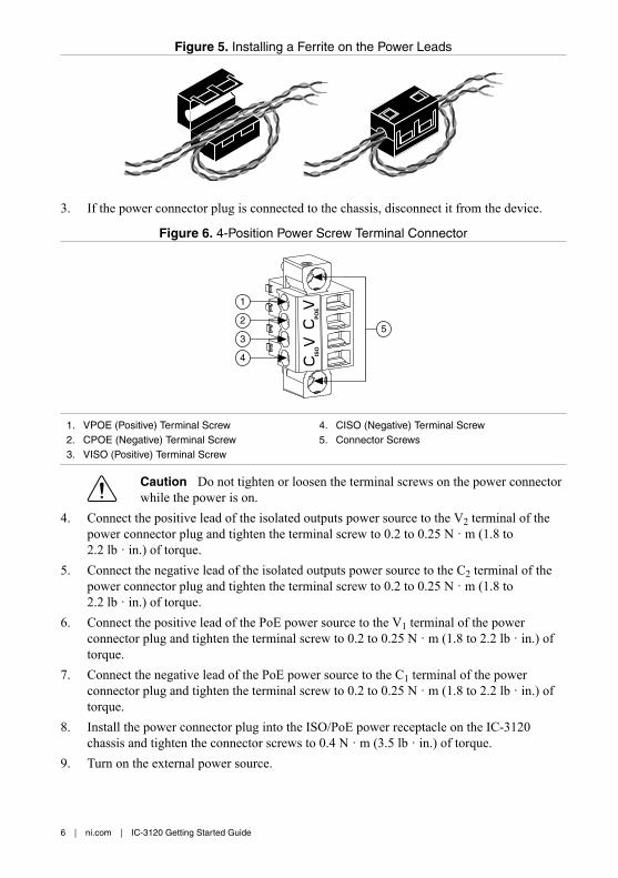
Figure 5. Installing a Ferrite on the Power Leads
3. If the power connector plug is connected to the chassis, disconnect it from the device.
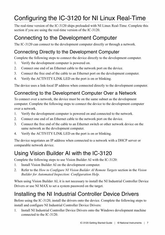
Figure 6. 4-Position Power Screw Terminal Connector
2
1
5
ISO
PO
E
4
3
1. VPOE (Positive) Terminal Screw2. CPOE (Negative) Terminal Screw3. VISO (Positive) Terminal Screw
4. CISO (Negative) Terminal Screw5. Connector Screws
Caution Do not tighten or loosen the terminal screws on the power connectorwhile the power is on.
4. Connect the positive lead of the isolated outputs power source to the V2 terminal of thepower connector plug and tighten the terminal screw to 0.2 to 0.25 N · m (1.8 to2.2 lb · in.) of torque.
5. Connect the negative lead of the isolated outputs power source to the C2 terminal of thepower connector plug and tighten the terminal screw to 0.2 to 0.25 N · m (1.8 to2.2 lb · in.) of torque.
6. Connect the positive lead of the PoE power source to the V1 terminal of the powerconnector plug and tighten the terminal screw to 0.2 to 0.25 N · m (1.8 to 2.2 lb · in.) oftorque.
7. Connect the negative lead of the PoE power source to the C1 terminal of the powerconnector plug and tighten the terminal screw to 0.2 to 0.25 N · m (1.8 to 2.2 lb · in.) oftorque.
8. Install the power connector plug into the ISO/PoE power receptacle on the IC-3120chassis and tighten the connector screws to 0.4 N · m (3.5 lb · in.) of torque.
9. Turn on the external power source.
6 | ni.com | IC-3120 Getting Started Guide
Configuring the IC-3120 for NI Linux Real-TimeThe real-time version of the IC-3120 ships preloaded with NI Linux Real-Time. Complete thissection if you are using the real-time version of the IC-3120.
Connecting to the Development ComputerThe IC-3120 can connect to the development computer directly or through a network.
Connecting Directly to the Development ComputerComplete the following steps to connect the device directly to the development computer.1. Verify the development computer is powered on.2. Connect one end of an Ethernet cable to the network port on the device.3. Connect the free end of the cable to an Ethernet port on the development computer.4. Verify the ACTIVITY/LINK LED on the port is on or blinking.
The device uses a link-local IP address when connected directly to the development computer.
Connecting to the Development Computer Over a NetworkTo connect over a network, the device must be on the same subnet as the developmentcomputer. Complete the following steps to connect the device to the development computerover a network.1. Verify the development computer is powered on and connected to the network.2. Connect one end of an Ethernet cable to the network port on the device.3. Connect the free end of the cable to an Ethernet switch or other network device on the
same network as the development computer.4. Verify the ACTIVITY/LINK LED on the port is on or blinking.
The device negotiates an IP address when connected to a network with a DHCP server orcomparable network device.
Using Vision Builder AI with the IC-3120Complete the following steps to use Vision Builder AI with the IC-3120:1. Install Vision Builder AI on the development computer.2. Refer to the How to Configure NI Vision Builder AI Remote Targets section in the Vision
Builder for Automated Inspection: Configuration Help.
When using Vision Builder AI, it is not necessary to install the NI Industrial Controller DeviceDrivers or use NI MAX to set a system password on the target.
Installing the NI Industrial Controller Device DriversBefore using the IC-3120, install the drivers onto the device. Complete the following steps toinstall and configure NI Industrial Controller Device Drivers:1. Install NI Industrial Controller Device Drivers onto the Windows development machine
connected to the IC-3120.
IC-3120 Getting Started Guide | © National Instruments | 7
2. Run NI MAX.3. Expand the Remote Systems list in the configuration tree.4. Select the IC-3120 in the list. By default, MAX lists devices by the model number
followed by the serial number, such as IC-3120-XXXXXXXX.5. Configure the network settings for the IC-3120. Refer to the Remote Systems Help in
MAX. Select Help»Help Topics»Remote Systems for instructions about configuringnetwork settings.
6. Install a recommended software set. If you would like to install custom software insteadof a recommended software set, proceed to the next step.a) Expand the IC-3120 under Remote Systems.b) Click the Software item below the IC-3120 in the configuration tree.c) Click Add/Remove Software on the MAX toolbar to launch the LabVIEW Real-
Time Software Wizard.d) Enter admin as the username and leave the password field blank.e) Select NI Industrial Controller under the version of LabVIEW Real-Time you are
using.f) Click Next.g) Select any additional add-ons you would like to install to the IC-3120.h) Click Next. Review the list of software to install.i) Click Next to begin downloading the software to the IC-3120. When MAX finishes
downloading the software, the IC-3120 restarts.j) Click Finish.
7. Install custom software. You do not need to install custom software if you installed arecommended software set.a) Expand the IC-3120 under Remote Systems.b) Click the Software item below the IC-3120 in the configuration tree.c) Click Add/Remove Software on the NI MAX toolbar to launch the LabVIEW Real-
Time Software Wizard.d) Enter admin as the username and leave the password field blank.e) If you are given a choice of recommended software sets, choose Custom software
installation and click Next to proceed with a custom installation.f) Select the NI Industrial Controller Device Drivers, and any additional software you
would like to install on the IC-3120.g) Click Next. Review the list of software to install.h) Click Next to begin downloading the software to the IC-3120. When NI MAX
finishes downloading the software, the IC-3120 restarts.i) Click Finish.
8. Connect hardware to the IC-3120. The NI Industrial Controller Device Drivers enable theIC-3120 to detect any hardware connected.
9. Select the target in the configuration tree and click the Refresh button. Refresh the targetwhenever you connect new hardware.
10. Expand Devices and Interfaces under the IC-3120 in the configuration tree. Select thehardware connected to the IC-3120 from the list. You can view or modify the devicesettings as allowed by the hardware.
8 | ni.com | IC-3120 Getting Started Guide
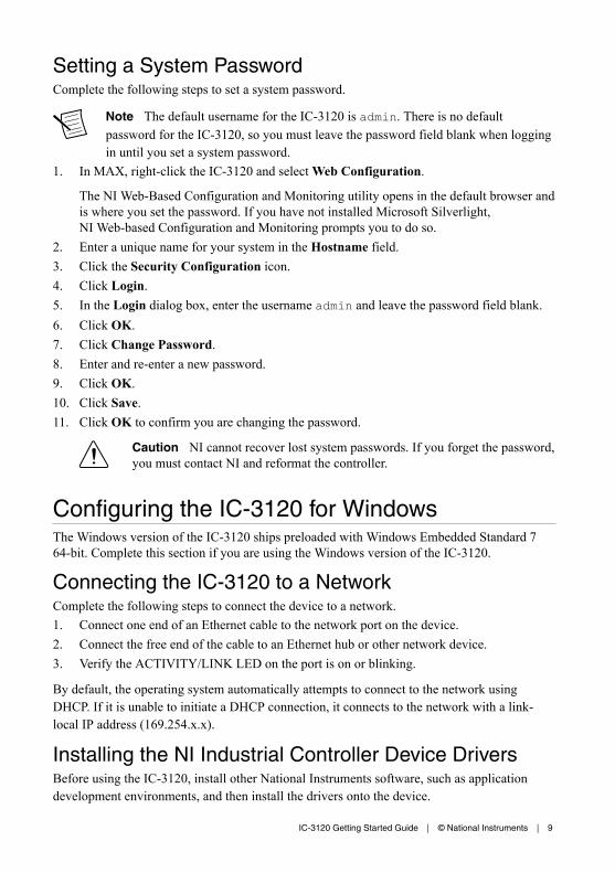
Setting a System PasswordComplete the following steps to set a system password.
Note The default username for the IC-3120 is admin. There is no defaultpassword for the IC-3120, so you must leave the password field blank when loggingin until you set a system password.
1. In MAX, right-click the IC-3120 and select Web Configuration.
The NI Web-Based Configuration and Monitoring utility opens in the default browser andis where you set the password. If you have not installed Microsoft Silverlight,NI Web-based Configuration and Monitoring prompts you to do so.
2. Enter a unique name for your system in the Hostname field.3. Click the Security Configuration icon.4. Click Login.5. In the Login dialog box, enter the username admin and leave the password field blank.6. Click OK.7. Click Change Password.8. Enter and re-enter a new password.9. Click OK.10. Click Save.11. Click OK to confirm you are changing the password.
Caution NI cannot recover lost system passwords. If you forget the password,you must contact NI and reformat the controller.
Configuring the IC-3120 for WindowsThe Windows version of the IC-3120 ships preloaded with Windows Embedded Standard 764-bit. Complete this section if you are using the Windows version of the IC-3120.
Connecting the IC-3120 to a NetworkComplete the following steps to connect the device to a network.1. Connect one end of an Ethernet cable to the network port on the device.2. Connect the free end of the cable to an Ethernet hub or other network device.3. Verify the ACTIVITY/LINK LED on the port is on or blinking.
By default, the operating system automatically attempts to connect to the network usingDHCP. If it is unable to initiate a DHCP connection, it connects to the network with a link-local IP address (169.254.x.x).
Installing the NI Industrial Controller Device DriversBefore using the IC-3120, install other National Instruments software, such as applicationdevelopment environments, and then install the drivers onto the device.
IC-3120 Getting Started Guide | © National Instruments | 9
If you have an external USB DVD drive, you can use the external DVD drive to install the NIIndustrial Controller Device Drivers from the DVD shipped with the device. Otherwise,complete the following steps to download and install the NI Industrial Controller DeviceDrivers1. Connect a USB keyboard and a USB mouse to the USB ports on the IC-3120.2. Connect a monitor to the VGA on the IC-3120.3. Using the web browser on the IC-3120, navigate to ni.com/drivers.4. In the Drivers search field, search for NI Industrial Controller Device Drivers.5. Download the latest version of NI Industrial Controller Device Drivers.6. Run the NI Industrial Controller Device Drivers installer.
TroubleshootingThe following sections provide instructions for troubleshooting the IC-3120.
(RT Only) The IC-3120 Does Not Appear in MAX• The IC-3120 may not be powered. Verify that there is system power to the device and that
both the IC-3120 and the development computer are properly connected to the network.The PWR/FAULT LED should be lit green and the ACTIVITY/LINK LED on theprimary network port should flash green when refreshing the list of devices in MAX.
• Ensure you are connecting to the IC-3120 from a Windows development machine with NIIndustrial Controller Device Drivers installed.
• The IC-3120 may have been configured on another network and then moved to thecurrent network. Reconfigure the IC-3120 for the current network.
Note Connect a monitor and keyboard to the IC-3120 and press <Enter> toview the current configuration settings of the device.
• Another device on the network is using the IP address assigned to the IC-3120. This canhappen when you assign the same static IP to two devices, you assign a static IP that is inthe range of the IP address available for DHCP use on your network, or the DHCPassigns the same IP address to another device. Either remove or reconfigure the otherdevice, or reconfigure the IC-3120 to use a different IP address by putting it into the IPRESET state and restarting into the normal state. Refer to the IC-3120 User Manual on ni.com/manuals for instructions on how to perform an IP RESET.
• The cable you are using may be inappropriate for the speed of your network, causingnetwork communication dropout. While 1,000 Mbps communication over short cablelengths can be achieved with the CAT5 cable commonly used for 10 and 100 Mbps,CAT5e and CAT6 cables are more reliable and recommended for 1,000 Mbps links. TheIC-3120 has the ability to perform auto-crossover, allowing the use of straight orcrossover Ethernet cables, independent of the connection configuration.
• The IC-3120 is configured to acquire an IP address from a DHCP server, but no DHCPserver is available. By default, the target will automatically attempt to connect to the
10 | ni.com | IC-3120 Getting Started Guide
network using DHCP. If the target is unable to initiate a DHCP connection, the targetconnects to the network with a link-local IP address (169.254.x.x).
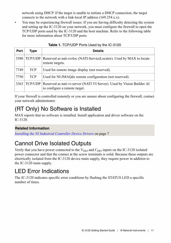
• You may be experiencing firewall issues. If you are having difficulty detecting the systemand setting up the IC-3120 on your network, you must configure the firewall to open theTCP/UDP ports used by the IC-3120 and the host machine. Refer to the following tablefor more information about TCP/UDP ports.
Table 1. TCP/UDP Ports Used by the IC-3120
Port Type Details
3580 TCP/UDP Reserved as nati-svrloc (NATI-ServiceLocator). Used by MAX to locateremote targets.
7749 TCP Used for remote image display (not reserved).
7750 TCP Used for NI-IMAQdx remote configuration (not reserved).
3363 TCP/UDP Reserved as nati-vi-server (NATI VI Server). Used by Vision Builder AIto configure a remote target.
If your firewall is controlled remotely or you are unsure about configuring the firewall, contactyour network administrator.
(RT Only) No Software is InstalledMAX reports that no software is installed. Install application and driver software on theIC-3120.
Related InformationInstalling the NI Industrial Controller Device Drivers on page 7
Cannot Drive Isolated OutputsVerify that you have power connected to the VISO and CISO inputs on the IC-3120 isolatedpower connector and that the contact at the screw terminals is solid. Because these outputs areelectrically isolated from the IC-3120 device main supply, they require power in addition tothe IC-3120 main supply.
LED Error IndicationsThe IC-3120 indicates specific error conditions by flashing the STATUS LED a specificnumber of times.
IC-3120 Getting Started Guide | © National Instruments | 11
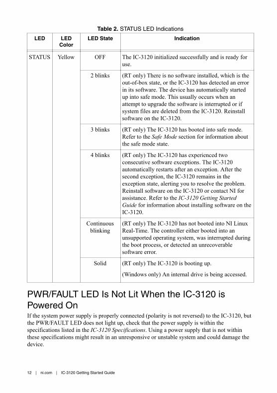
Table 2. STATUS LED Indications
LED LEDColor
LED State Indication
STATUS Yellow OFF The IC-3120 initialized successfully and is ready foruse.
2 blinks (RT only) There is no software installed, which is theout-of-box state, or the IC-3120 has detected an errorin its software. The device has automatically startedup into safe mode. This usually occurs when anattempt to upgrade the software is interrupted or ifsystem files are deleted from the IC-3120. Reinstallsoftware on the IC-3120.
3 blinks (RT only) The IC-3120 has booted into safe mode.Refer to the Safe Mode section for information aboutthe safe mode state.
4 blinks (RT only) The IC-3120 has experienced twoconsecutive software exceptions. The IC-3120automatically restarts after an exception. After thesecond exception, the IC-3120 remains in theexception state, alerting you to resolve the problem.Reinstall software on the IC-3120 or contact NI forassistance. Refer to the IC-3120 Getting StartedGuide for information about installing software on theIC-3120.
Continuousblinking
(RT only) The IC-3120 has not booted into NI LinuxReal-Time. The controller either booted into anunsupported operating system, was interrupted duringthe boot process, or detected an unrecoverablesoftware error.
Solid (RT only) The IC-3120 is booting up.
(Windows only) An internal drive is being accessed.
PWR/FAULT LED Is Not Lit When the IC-3120 isPowered OnIf the system power supply is properly connected (polarity is not reversed) to the IC-3120, butthe PWR/FAULT LED does not light up, check that the power supply is within thespecifications listed in the IC-3120 Specifications. Using a power supply that is not withinthese specifications might result in an unresponsive or unstable system and could damage thedevice.
12 | ni.com | IC-3120 Getting Started Guide
If the BIOS setting Restore After Power Loss is set to Stay Off, the IC-3120 may be powered,but turned off. Use the power button to turn on the device.
Where to Go NextThe following documents and resources contain information you may find helpful as you usethe IC-3120 in an application. Refer to the National Instruments Product Manuals Library at ni.com/manuals for the most recent versions of product documentation.• IC-3120 Specifications—Contains detailed specifications for the IC-3120.• IC-3120 User Manual—Contains connector pinouts, configuration information, mounting
information, and answers to common troubleshooting questions.• NI CVS I/O Accessory User Manual—Contains installation and operation instructions for
the NI CVS I/O Accessory.
Worldwide Support and ServicesThe NI website is your complete resource for technical support. At ni.com/support, you haveaccess to everything from troubleshooting and application development self-help resources toemail and phone assistance from NI Application Engineers.
Visit ni.com/services for NI Factory Installation Services, repairs, extended warranty, andother services.
Visit ni.com/register to register your NI product. Product registration facilitates technicalsupport and ensures that you receive important information updates from NI.
A Declaration of Conformity (DoC) is our claim of compliance with the Council of theEuropean Communities using the manufacturer’s declaration of conformity. This systemaffords the user protection for electromagnetic compatibility (EMC) and product safety. Youcan obtain the DoC for your product by visiting ni.com/certification. If your product supportscalibration, you can obtain the calibration certificate for your product at ni.com/calibration.
NI corporate headquarters is located at 11500 North Mopac Expressway, Austin, Texas,78759-3504. NI also has offices located around the world. For telephone support in the UnitedStates, create your service request at ni.com/support or dial 1 866 ASK MYNI (275 6964). Fortelephone support outside the United States, visit the Worldwide Offices section of ni.com/niglobal to access the branch office websites, which provide up-to-date contact information,support phone numbers, email addresses, and current events.
IC-3120 Getting Started Guide | © National Instruments | 13

Refer to the NI Trademarks and Logo Guidelines at ni.com/trademarks for information on NI trademarks. Other product andcompany names mentioned herein are trademarks or trade names of their respective companies. For patents covering NIproducts/technology, refer to the appropriate location: Help»Patents in your software, the patents.txt file on your media, or theNational Instruments Patent Notice at ni.com/patents. You can find information about end-user license agreements (EULAs)and third-party legal notices in the readme file for your NI product. Refer to the Export Compliance Information at ni.com/legal/export-compliance for the NI global trade compliance policy and how to obtain relevant HTS codes, ECCNs, and otherimport/export data. NI MAKES NO EXPRESS OR IMPLIED WARRANTIES AS TO THE ACCURACY OF THE INFORMATIONCONTAINED HEREIN AND SHALL NOT BE LIABLE FOR ANY ERRORS. U.S. Government Customers: The data contained inthis manual was developed at private expense and is subject to the applicable limited rights and restricted data rights as set forthin FAR 52.227-14, DFAR 252.227-7014, and DFAR 252.227-7015.
© 2016 National Instruments. All rights reserved.
376069A-01 Apr16