Embed Size (px)
Citation preview
Redpaper
Front cover
IBM Power Systems S822LCTechnical Overview and Introduction
Alexandre Caldeira
Marc-Eric Kahle
Gerard Saverimuthu
K. C. Vearner

International Technical Support Organization
IBM Power Systems S822LC Technical Overview and Introduction
December 2015
REDP-5283-00
© Copyright International Business Machines Corporation 2015. All rights reserved.Note to U.S. Government Users Restricted Rights -- Use, duplication or disclosure restricted by GSA ADP ScheduleContract with IBM Corp.
First Edition (December 2015)
This edition applies to the IBM Power Systems S822LC models 8335-GTA and 8335-GCA.
Note: Before using this information and the product it supports, read the information in “Notices” on page vii.
Contents
Notices . . . . . . . . . . . . . . . . . . . . . . . . . . . . . . . . . . . . . . . . . . . . . . . . . . . . . . . . . . . . . . . . . viiTrademarks . . . . . . . . . . . . . . . . . . . . . . . . . . . . . . . . . . . . . . . . . . . . . . . . . . . . . . . . . . . . . viii
IBM Redbooks promotions . . . . . . . . . . . . . . . . . . . . . . . . . . . . . . . . . . . . . . . . . . . . . . . . . ix
Preface . . . . . . . . . . . . . . . . . . . . . . . . . . . . . . . . . . . . . . . . . . . . . . . . . . . . . . . . . . . . . . . . . xiAuthors. . . . . . . . . . . . . . . . . . . . . . . . . . . . . . . . . . . . . . . . . . . . . . . . . . . . . . . . . . . . . . . . . . xiiNow you can become a published author, too! . . . . . . . . . . . . . . . . . . . . . . . . . . . . . . . . . . . xiiComments welcome. . . . . . . . . . . . . . . . . . . . . . . . . . . . . . . . . . . . . . . . . . . . . . . . . . . . . . . xiiiStay connected to IBM Redbooks . . . . . . . . . . . . . . . . . . . . . . . . . . . . . . . . . . . . . . . . . . . . xiii
Chapter 1. Architecture and technical description . . . . . . . . . . . . . . . . . . . . . . . . . . . . . 11.1 Power S822LC server . . . . . . . . . . . . . . . . . . . . . . . . . . . . . . . . . . . . . . . . . . . . . . . . . . . 21.2 Server features . . . . . . . . . . . . . . . . . . . . . . . . . . . . . . . . . . . . . . . . . . . . . . . . . . . . . . . . 2
1.2.1 Power S822LC model 8355-GCA server features . . . . . . . . . . . . . . . . . . . . . . . . . 31.2.2 Power S822LC model 8355-GTA server features. . . . . . . . . . . . . . . . . . . . . . . . . . 41.2.3 Minimum features . . . . . . . . . . . . . . . . . . . . . . . . . . . . . . . . . . . . . . . . . . . . . . . . . . 4
1.3 NVIDIA Tesla GPU Accelerators. . . . . . . . . . . . . . . . . . . . . . . . . . . . . . . . . . . . . . . . . . . 51.3.1 NVIDIA Compute Unified Device Architecture . . . . . . . . . . . . . . . . . . . . . . . . . . . . 7
1.4 Operating system support . . . . . . . . . . . . . . . . . . . . . . . . . . . . . . . . . . . . . . . . . . . . . . . . 81.5 Linux operating system . . . . . . . . . . . . . . . . . . . . . . . . . . . . . . . . . . . . . . . . . . . . . . . . . . 8
1.5.1 Ubuntu . . . . . . . . . . . . . . . . . . . . . . . . . . . . . . . . . . . . . . . . . . . . . . . . . . . . . . . . . . 81.5.2 Red Hat . . . . . . . . . . . . . . . . . . . . . . . . . . . . . . . . . . . . . . . . . . . . . . . . . . . . . . . . . . 81.5.3 Additional information . . . . . . . . . . . . . . . . . . . . . . . . . . . . . . . . . . . . . . . . . . . . . . . 8
1.6 Operating environment . . . . . . . . . . . . . . . . . . . . . . . . . . . . . . . . . . . . . . . . . . . . . . . . . . 91.7 Physical package . . . . . . . . . . . . . . . . . . . . . . . . . . . . . . . . . . . . . . . . . . . . . . . . . . . . . . 91.8 System architecture . . . . . . . . . . . . . . . . . . . . . . . . . . . . . . . . . . . . . . . . . . . . . . . . . . . 101.9 The POWER8 processor. . . . . . . . . . . . . . . . . . . . . . . . . . . . . . . . . . . . . . . . . . . . . . . . 12
1.9.1 POWER8 processor overview. . . . . . . . . . . . . . . . . . . . . . . . . . . . . . . . . . . . . . . . 121.9.2 POWER8 processor core . . . . . . . . . . . . . . . . . . . . . . . . . . . . . . . . . . . . . . . . . . . 141.9.3 Simultaneous multithreading. . . . . . . . . . . . . . . . . . . . . . . . . . . . . . . . . . . . . . . . . 151.9.4 Memory access. . . . . . . . . . . . . . . . . . . . . . . . . . . . . . . . . . . . . . . . . . . . . . . . . . . 151.9.5 On-chip L3 cache innovation and Intelligent Cache . . . . . . . . . . . . . . . . . . . . . . . 161.9.6 L4 cache and memory buffer . . . . . . . . . . . . . . . . . . . . . . . . . . . . . . . . . . . . . . . . 171.9.7 Hardware transactional memory . . . . . . . . . . . . . . . . . . . . . . . . . . . . . . . . . . . . . . 181.9.8 Coherent Accelerator Processor Interface . . . . . . . . . . . . . . . . . . . . . . . . . . . . . . 18
1.10 Memory subsystem . . . . . . . . . . . . . . . . . . . . . . . . . . . . . . . . . . . . . . . . . . . . . . . . . . . 201.10.1 Memory riser cards . . . . . . . . . . . . . . . . . . . . . . . . . . . . . . . . . . . . . . . . . . . . . . . 201.10.2 Memory placement rules. . . . . . . . . . . . . . . . . . . . . . . . . . . . . . . . . . . . . . . . . . . 211.10.3 Memory bandwidth . . . . . . . . . . . . . . . . . . . . . . . . . . . . . . . . . . . . . . . . . . . . . . . 23
1.11 System bus . . . . . . . . . . . . . . . . . . . . . . . . . . . . . . . . . . . . . . . . . . . . . . . . . . . . . . . . . 241.12 Internal I/O subsystem . . . . . . . . . . . . . . . . . . . . . . . . . . . . . . . . . . . . . . . . . . . . . . . . 261.13 Slot configuration . . . . . . . . . . . . . . . . . . . . . . . . . . . . . . . . . . . . . . . . . . . . . . . . . . . . 261.14 System ports . . . . . . . . . . . . . . . . . . . . . . . . . . . . . . . . . . . . . . . . . . . . . . . . . . . . . . . . 271.15 PCI adapters . . . . . . . . . . . . . . . . . . . . . . . . . . . . . . . . . . . . . . . . . . . . . . . . . . . . . . . . 28
1.15.1 PCI Express . . . . . . . . . . . . . . . . . . . . . . . . . . . . . . . . . . . . . . . . . . . . . . . . . . . . 281.15.2 LAN adapters . . . . . . . . . . . . . . . . . . . . . . . . . . . . . . . . . . . . . . . . . . . . . . . . . . . 281.15.3 Compute Intensive Accelerator . . . . . . . . . . . . . . . . . . . . . . . . . . . . . . . . . . . . . . 291.15.4 Fibre Channel adapters . . . . . . . . . . . . . . . . . . . . . . . . . . . . . . . . . . . . . . . . . . . 30
© Copyright IBM Corp. 2015. All rights reserved. iii
1.15.5 CAPI adapters. . . . . . . . . . . . . . . . . . . . . . . . . . . . . . . . . . . . . . . . . . . . . . . . . . . 301.15.6 Flash storage adapters . . . . . . . . . . . . . . . . . . . . . . . . . . . . . . . . . . . . . . . . . . . . 30
1.16 Internal storage . . . . . . . . . . . . . . . . . . . . . . . . . . . . . . . . . . . . . . . . . . . . . . . . . . . . . . 311.16.1 Disk and media features . . . . . . . . . . . . . . . . . . . . . . . . . . . . . . . . . . . . . . . . . . . 32
1.17 External I/O subsystems . . . . . . . . . . . . . . . . . . . . . . . . . . . . . . . . . . . . . . . . . . . . . . . 321.18 IBM System Storage . . . . . . . . . . . . . . . . . . . . . . . . . . . . . . . . . . . . . . . . . . . . . . . . . . 321.19 Java. . . . . . . . . . . . . . . . . . . . . . . . . . . . . . . . . . . . . . . . . . . . . . . . . . . . . . . . . . . . . . . 34
Chapter 2. Management and virtualization . . . . . . . . . . . . . . . . . . . . . . . . . . . . . . . . . . . 352.1 Main management components overview. . . . . . . . . . . . . . . . . . . . . . . . . . . . . . . . . . . 362.2 Service processor . . . . . . . . . . . . . . . . . . . . . . . . . . . . . . . . . . . . . . . . . . . . . . . . . . . . . 36
2.2.1 Open Power Abstraction Layer . . . . . . . . . . . . . . . . . . . . . . . . . . . . . . . . . . . . . . . 372.2.2 Intelligent Platform Management Interface . . . . . . . . . . . . . . . . . . . . . . . . . . . . . . 372.2.3 Petitboot bootloader . . . . . . . . . . . . . . . . . . . . . . . . . . . . . . . . . . . . . . . . . . . . . . . 38
2.3 IBM PowerKVM. . . . . . . . . . . . . . . . . . . . . . . . . . . . . . . . . . . . . . . . . . . . . . . . . . . . . . . 382.3.1 Downloading PowerKVM . . . . . . . . . . . . . . . . . . . . . . . . . . . . . . . . . . . . . . . . . . . 392.3.2 Updating PowerKVM. . . . . . . . . . . . . . . . . . . . . . . . . . . . . . . . . . . . . . . . . . . . . . . 392.3.3 Upgrading PowerKVM . . . . . . . . . . . . . . . . . . . . . . . . . . . . . . . . . . . . . . . . . . . . . 392.3.4 Kimchi management tool . . . . . . . . . . . . . . . . . . . . . . . . . . . . . . . . . . . . . . . . . . . 39
2.4 PowerVC . . . . . . . . . . . . . . . . . . . . . . . . . . . . . . . . . . . . . . . . . . . . . . . . . . . . . . . . . . . . 402.4.1 Benefits . . . . . . . . . . . . . . . . . . . . . . . . . . . . . . . . . . . . . . . . . . . . . . . . . . . . . . . . . 402.4.2 New features. . . . . . . . . . . . . . . . . . . . . . . . . . . . . . . . . . . . . . . . . . . . . . . . . . . . . 402.4.3 Lifecycle . . . . . . . . . . . . . . . . . . . . . . . . . . . . . . . . . . . . . . . . . . . . . . . . . . . . . . . . 41
Chapter 3. Reliability, availability, and serviceability. . . . . . . . . . . . . . . . . . . . . . . . . . . 433.1 Introduction . . . . . . . . . . . . . . . . . . . . . . . . . . . . . . . . . . . . . . . . . . . . . . . . . . . . . . . . . . 44
3.1.1 RAS enhancements of POWER8 processor-based scale-out servers . . . . . . . . . 443.2 IBM terminology versus x86 terminology . . . . . . . . . . . . . . . . . . . . . . . . . . . . . . . . . . . 453.3 Error handling . . . . . . . . . . . . . . . . . . . . . . . . . . . . . . . . . . . . . . . . . . . . . . . . . . . . . . . . 45
3.3.1 Processor core/cache correctable error handling . . . . . . . . . . . . . . . . . . . . . . . . . 453.3.2 Processor Instruction Retry and other try again techniques . . . . . . . . . . . . . . . . . 463.3.3 Other processor chip functions . . . . . . . . . . . . . . . . . . . . . . . . . . . . . . . . . . . . . . . 46
3.4 Serviceability . . . . . . . . . . . . . . . . . . . . . . . . . . . . . . . . . . . . . . . . . . . . . . . . . . . . . . . . . 463.4.1 Detection introduction . . . . . . . . . . . . . . . . . . . . . . . . . . . . . . . . . . . . . . . . . . . . . . 473.4.2 Error checkers and fault isolation registers . . . . . . . . . . . . . . . . . . . . . . . . . . . . . . 473.4.3 Service processor . . . . . . . . . . . . . . . . . . . . . . . . . . . . . . . . . . . . . . . . . . . . . . . . . 473.4.4 Diagnosing . . . . . . . . . . . . . . . . . . . . . . . . . . . . . . . . . . . . . . . . . . . . . . . . . . . . . . 483.4.5 General problem determination. . . . . . . . . . . . . . . . . . . . . . . . . . . . . . . . . . . . . . . 483.4.6 Error handling and reporting . . . . . . . . . . . . . . . . . . . . . . . . . . . . . . . . . . . . . . . . . 493.4.7 Locating and servicing . . . . . . . . . . . . . . . . . . . . . . . . . . . . . . . . . . . . . . . . . . . . . 50
3.5 Manageability . . . . . . . . . . . . . . . . . . . . . . . . . . . . . . . . . . . . . . . . . . . . . . . . . . . . . . . . 523.5.1 Service user interfaces . . . . . . . . . . . . . . . . . . . . . . . . . . . . . . . . . . . . . . . . . . . . . 523.5.2 IBM Power Systems Firmware maintenance . . . . . . . . . . . . . . . . . . . . . . . . . . . . 533.5.3 Updating the system firmware with the ipmitool command. . . . . . . . . . . . . . . . . . 543.5.4 Updating the ipmitool on Ubuntu. . . . . . . . . . . . . . . . . . . . . . . . . . . . . . . . . . . . . . 543.5.5 Statement of direction: Updating the system firmware by using the Advanced System
Management console . . . . . . . . . . . . . . . . . . . . . . . . . . . . . . . . . . . . . . . . . . . . . . 56
Appendix A. Server racks and energy management . . . . . . . . . . . . . . . . . . . . . . . . . . . 63IBM server racks . . . . . . . . . . . . . . . . . . . . . . . . . . . . . . . . . . . . . . . . . . . . . . . . . . . . . . . . . 64IBM 7014 Model S25 rack . . . . . . . . . . . . . . . . . . . . . . . . . . . . . . . . . . . . . . . . . . . . . . . . . . 64IBM 7014 Model T00 rack . . . . . . . . . . . . . . . . . . . . . . . . . . . . . . . . . . . . . . . . . . . . . . . . . . 64IBM 7014 Model T42 rack . . . . . . . . . . . . . . . . . . . . . . . . . . . . . . . . . . . . . . . . . . . . . . . . . . 65IBM 42U SlimRack 7965-94Y . . . . . . . . . . . . . . . . . . . . . . . . . . . . . . . . . . . . . . . . . . . . . . . 67
iv IBM Power Systems S822LC Technical Overview and Introduction
Feature code 0551 rack . . . . . . . . . . . . . . . . . . . . . . . . . . . . . . . . . . . . . . . . . . . . . . . . . . . . 67Feature code 0553 rack . . . . . . . . . . . . . . . . . . . . . . . . . . . . . . . . . . . . . . . . . . . . . . . . . . . . 67Feature code ER05 rack . . . . . . . . . . . . . . . . . . . . . . . . . . . . . . . . . . . . . . . . . . . . . . . . . . . 67The AC power distribution unit and rack content . . . . . . . . . . . . . . . . . . . . . . . . . . . . . . . . . 68Rack-mounting rules . . . . . . . . . . . . . . . . . . . . . . . . . . . . . . . . . . . . . . . . . . . . . . . . . . . . . . 71Useful rack additions . . . . . . . . . . . . . . . . . . . . . . . . . . . . . . . . . . . . . . . . . . . . . . . . . . . . . . 71OEM racks . . . . . . . . . . . . . . . . . . . . . . . . . . . . . . . . . . . . . . . . . . . . . . . . . . . . . . . . . . . . . . 71Energy management . . . . . . . . . . . . . . . . . . . . . . . . . . . . . . . . . . . . . . . . . . . . . . . . . . . . . . 73IBM EnergyScale technology . . . . . . . . . . . . . . . . . . . . . . . . . . . . . . . . . . . . . . . . . . . . . . . . 74On Chip Controller . . . . . . . . . . . . . . . . . . . . . . . . . . . . . . . . . . . . . . . . . . . . . . . . . . . . . . . . 76Energy consumption estimation . . . . . . . . . . . . . . . . . . . . . . . . . . . . . . . . . . . . . . . . . . . . . . 76
Related publications . . . . . . . . . . . . . . . . . . . . . . . . . . . . . . . . . . . . . . . . . . . . . . . . . . . . . 77IBM Redbooks . . . . . . . . . . . . . . . . . . . . . . . . . . . . . . . . . . . . . . . . . . . . . . . . . . . . . . . . . . . 77Other publications . . . . . . . . . . . . . . . . . . . . . . . . . . . . . . . . . . . . . . . . . . . . . . . . . . . . . . . . 77Online resources . . . . . . . . . . . . . . . . . . . . . . . . . . . . . . . . . . . . . . . . . . . . . . . . . . . . . . . . . 78Help from IBM . . . . . . . . . . . . . . . . . . . . . . . . . . . . . . . . . . . . . . . . . . . . . . . . . . . . . . . . . . . 79
Contents v

vi IBM Power Systems S822LC Technical Overview and Introduction

Notices
This information was developed for products and services offered in the U.S.A.
IBM may not offer the products, services, or features discussed in this document in other countries. Consult your local IBM representative for information on the products and services currently available in your area. Any reference to an IBM product, program, or service is not intended to state or imply that only that IBM product, program, or service may be used. Any functionally equivalent product, program, or service that does not infringe any IBM intellectual property right may be used instead. However, it is the user's responsibility to evaluate and verify the operation of any non-IBM product, program, or service.
IBM may have patents or pending patent applications covering subject matter described in this document. The furnishing of this document does not grant you any license to these patents. You can send license inquiries, in writing, to: IBM Director of Licensing, IBM Corporation, North Castle Drive, Armonk, NY 10504-1785 U.S.A.
The following paragraph does not apply to the United Kingdom or any other country where such provisions are inconsistent with local law: INTERNATIONAL BUSINESS MACHINES CORPORATION PROVIDES THIS PUBLICATION "AS IS" WITHOUT WARRANTY OF ANY KIND, EITHER EXPRESS OR IMPLIED, INCLUDING, BUT NOT LIMITED TO, THE IMPLIED WARRANTIES OF NON-INFRINGEMENT, MERCHANTABILITY OR FITNESS FOR A PARTICULAR PURPOSE. Some states do not allow disclaimer of express or implied warranties in certain transactions, therefore, this statement may not apply to you.
This information could include technical inaccuracies or typographical errors. Changes are periodically made to the information herein; these changes will be incorporated in new editions of the publication. IBM may make improvements and/or changes in the product(s) and/or the program(s) described in this publication at any time without notice.
Any references in this information to non-IBM websites are provided for convenience only and do not in any manner serve as an endorsement of those websites. The materials at those websites are not part of the materials for this IBM product and use of those websites is at your own risk.
IBM may use or distribute any of the information you supply in any way it believes appropriate without incurring any obligation to you.
Any performance data contained herein was determined in a controlled environment. Therefore, the results obtained in other operating environments may vary significantly. Some measurements may have been made on development-level systems and there is no guarantee that these measurements will be the same on generally available systems. Furthermore, some measurements may have been estimated through extrapolation. Actual results may vary. Users of this document should verify the applicable data for their specific environment.
Information concerning non-IBM products was obtained from the suppliers of those products, their published announcements or other publicly available sources. IBM has not tested those products and cannot confirm the accuracy of performance, compatibility or any other claims related to non-IBM products. Questions on the capabilities of non-IBM products should be addressed to the suppliers of those products.
This information contains examples of data and reports used in daily business operations. To illustrate them as completely as possible, the examples include the names of individuals, companies, brands, and products. All of these names are fictitious and any similarity to the names and addresses used by an actual business enterprise is entirely coincidental.
COPYRIGHT LICENSE:
This information contains sample application programs in source language, which illustrate programming techniques on various operating platforms. You may copy, modify, and distribute these sample programs in any form without payment to IBM, for the purposes of developing, using, marketing or distributing application programs conforming to the application programming interface for the operating platform for which the sample programs are written. These examples have not been thoroughly tested under all conditions. IBM, therefore, cannot guarantee or imply reliability, serviceability, or function of these programs.
© Copyright IBM Corp. 2015. All rights reserved. vii
Trademarks
IBM, the IBM logo, and ibm.com are trademarks or registered trademarks of International Business Machines Corporation in the United States, other countries, or both. These and other IBM trademarked terms are marked on their first occurrence in this information with the appropriate symbol (® or ™), indicating US registered or common law trademarks owned by IBM at the time this information was published. Such trademarks may also be registered or common law trademarks in other countries. A current list of IBM trademarks is available on the Web at http://www.ibm.com/legal/copytrade.shtml
The following terms are trademarks of the International Business Machines Corporation in the United States, other countries, or both:
AIX®DS8000®Easy Tier®EnergyScale™FlashSystem™Global Technology Services®IBM®IBM z Systems™POWER®
POWER Hypervisor™Power Systems™POWER7®POWER7+™POWER8®PowerHA®PowerLinux™PowerPC®PowerVM®
Real-time Compression™Redbooks®Redpaper™Redbooks (logo) ®RS/6000®Storwize®System Storage®XIV®
The following terms are trademarks of other companies:
Linux is a trademark of Linus Torvalds in the United States, other countries, or both.
Java, and all Java-based trademarks and logos are trademarks or registered trademarks of Oracle and/or its affiliates.
UNIX is a registered trademark of The Open Group in the United States and other countries.
Other company, product, or service names may be trademarks or service marks of others.
viii IBM Power Systems S822LC Technical Overview and Introduction
IBM REDBOOKS PROMOTIONS
Find and read thousands of IBM Redbooks publications
Search, bookmark, save and organize favorites
Get up-to-the-minute Redbooks news and announcements
Link to the latest Redbooks blogs and videos
DownloadNow
Get the latest version of the Redbooks Mobile App
iOS
Android
Place a Sponsorship Promotion in an IBM Redbooks publication, featuring your business or solution with a link to your web site.
Qualified IBM Business Partners may place a full page promotion in the most popular Redbooks publications. Imagine the power of being seen by users who download millions of Redbooks publications each year!
®
®
Promote your business in an IBM Redbooks publication
ibm.com/RedbooksAbout Redbooks Business Partner Programs
IBM Redbooks promotions

THIS PAGE INTENTIONALLY LEFT BLANK
Preface
This IBM® Redpaper™ publication is a comprehensive guide that covers the IBM Power Systems™ S822LC (8335-GCA and 8335-GTA) servers that use the latest IBM POWER8® processor technology and supports the Linux operating system (OS). The objective of this paper is to introduce the major innovative Power S822LC offerings and their relevant functions:
� Powerful POWER8 processors that offer 3.32 GHz or 2.92 GHz performance with eight or ten fully activated cores
� Superior throughput and performance for high-value Linux workloads, such as Linux, Apache, MariaDB, and PHP (LAMP), big data and analytics, or industry applications
� Low acquisition cost through system optimization (industry-standard memory, limited configurations, limited I/O and expansion, and industry-standard warranty)
� A strong innovation roadmap for graphics processor units (GPUs) accelerators
� More choices through open interfaces with tightly coupled Field Programmable Gate Arrays (FPGAs) and Coherent Accelerator Processor Interface (CAPI)
� Improved reliability, serviceability, and availability (RAS) functions
� IBM EnergyScale™ technology that provides features such as power trending, power-saving, capping of power, and thermal measurement
This publication is for professionals who want to acquire a better understanding of IBM Power Systems products. The intended audience includes the following roles:
� Clients
� Sales and marketing professionals
� Technical support professionals
� IBM Business Partners
� Independent software vendors
This paper expands the set of IBM Power Systems documentation by providing a desktop reference that offers a detailed technical description of the Power S822LC server.
This paper does not replace the latest marketing materials and configuration tools. It is intended as an additional source of information that, together with existing sources, can be used to enhance your knowledge of IBM server solutions.
© Copyright IBM Corp. 2015. All rights reserved. xi
Authors
This paper was produced by a team of specialists from around the world working at the International Technical Support Organization, Austin Center.
Alexandre Caldeira is a Certified IT Specialist and is a member of the Power Systems Product Management team for IBM Brazil. He holds a degree in computer science from the Universidade Estadual Paulista (UNESP) and an MBA in marketing. His major areas of focus are competition, sales, and technical sales support. Alexandre has more than 15 years of experience working on IBM Systems & Technology Group Solutions and worked also as an IBM Business Partner on Power Systems hardware, IBM AIX®, and IBM PowerVM® virtualization products.
Marc-Eric Kahle is a AIX Software specialist at the IBM Global Technology Services® in Ehningen, Germany. He worked as a Power Systems Hardware Support specialist in the IBM RS/6000®, Power Systems, and AIX fields since 1993. He has worked at IBM Germany since 1987. His areas of expertise include Power Systems hardware, and he is an AIX certified specialist. He participated in the development of eight other IBM Redbooks® publications.
Gerard Saverimuthu is a Consulting IT Specialist with the Systems-Hardware group in IBM Singapore. He has more than 11 years of experience in infrastructure design and systems consulting. He has worked for IBM Australia for four years, and was an IBM Business Partner earlier in his career. His major areas of expertise are pre-sales consulting for mid-range and enterprise clients. He is an IBM Certified Consulting IT Specialist, and IBM Certified Cloud Computing Infrastructure Architect. He holds a masters degree from Nanyang Technological.
K. C. Vearner is an AIX Technical Specialist in Austin, Texas, and has more than 15 years of experience in AIX on Power Systems. K.C. holds a Bachelor of Science degree in computer science from Park University, Parkville, Missouri. He is a Certified AIX Technical Expert and his area of expertise includes AIX system performance.
The project that produced this publication was managed by:
Scott VetterExecutive Project Manager, PMP
Thanks to the following people for their contributions to this project:
George Ahrens, Tamikia Barrow, Nick Bofferding, Charlie Burns, Sertac Cakici, Dan Crowell, Volker Haug, Daniel Henderson, Yesenia Jimenez, Ann Lund, Benjamin Mashak, Chris Mann, Michael J Mueller, Kanisha Patel, Matt Spinler, Jeff Stuecheli, Uma Yadlapati, and Maury Zipse.
Now you can become a published author, too!
Here’s an opportunity to spotlight your skills, grow your career, and become a published author—all at the same time! Join an ITSO residency project and help write a book in your area of expertise, while honing your experience using leading-edge technologies. Your efforts will help to increase product acceptance and customer satisfaction, as you expand your network of technical contacts and relationships. Residencies run from two to six weeks in length, and you can participate either in person or as a remote resident working from your home base.
xii IBM Power Systems S822LC Technical Overview and Introduction
Find out more about the residency program, browse the residency index, and apply online at:
ibm.com/redbooks/residencies.html
Comments welcome
Your comments are important to us!
We want our papers to be as helpful as possible. Send us your comments about this paper or other IBM Redbooks publications in one of the following ways:
� Use the online Contact us review Redbooks form found at:
ibm.com/redbooks
� Send your comments in an email to:
� Mail your comments to:
IBM Corporation, International Technical Support OrganizationDept. HYTD Mail Station P0992455 South RoadPoughkeepsie, NY 12601-5400
Stay connected to IBM Redbooks
� Find us on Facebook:
http://www.facebook.com/IBMRedbooks
� Follow us on Twitter:
http://twitter.com/ibmredbooks
� Look for us on LinkedIn:
http://www.linkedin.com/groups?home=&gid=2130806
� Explore new Redbooks publications, residencies, and workshops with the IBM Redbooks weekly newsletter:
https://www.redbooks.ibm.com/Redbooks.nsf/subscribe?OpenForm
� Stay current on recent Redbooks publications with RSS Feeds:
http://www.redbooks.ibm.com/rss.html
Preface xiii

xiv IBM Power Systems S822LC Technical Overview and Introduction
Chapter 1. Architecture and technical description
Built on industry standards and incorporating community innovation from the Open Power Foundation, the IBM Power Systems S822LC (8335-GCA and 8335-GTA) servers use the latest IBM POWER8 processor technology and are optimized for Linux to help deliver new solutions and services faster, with higher quality.
The Power Systems S822LC server is orderable in two different models:
1. Power S822LC model 8335-GTA server with two NVIDIA graphics processing units (GPU)
The Power S822LC technical computing server incorporates POWER8 processors, tightly coupled Field Programmable Gate Arrays (FPGAs) and accelerators, and faster I/O by using Coherent Accelerator Processor Interface (CAPI). Designed to accommodate two high-performance adapters, such as NVIDIA GPUs, this offering delivers a new class of technology that maximizes performance and efficiency for scientific, engineering, Java, big data analytics, and other technical computing workloads by simultaneously increasing workload density and reducing data center floorspace.
2. Power S822LC model 8335-GCA server without a NVIDIA graphics processing unit (GPU)
The Power S822LC commercial computing server delivers superior performance and throughput for cloud and business-critical applications with the only open standards-based system that ensures system utilization to achieve superior cloud economics. By supporting KVM virtualization and OpenStack, the Power S822LC server is designed to deliver unprecedented performance, scalability, reliability, and manageability for demanding commercial workloads.
The Power S822LC server offers a modular design to scale from single racks to hundreds, simplicity of ordering, and a strong innovation roadmap for GPUs.
For customers that are committed to Linux and open source applications and infrastructures, the Power S822LC servers provide the ideal foundation for private and public cloud infrastructure. Both servers, based on POWER8 technology, deliver superior throughput compared to x86-based offerings for comparable workloads, and provide superior economics for scale-out deployments.
1
© Copyright IBM Corp. 2015. All rights reserved. 1
The following sections provide detailed information about the Power S822LC server models.
1.1 Power S822LC server
The Power S822LC server is designed to deliver superior performance and throughput for high-value Linux workloads, such as industry applications, big data, and LAMP workloads.
The Power S822LC server is ideal for clients that need more processing power while simultaneously increasing workload density and reducing data center floorspace. It offers a modular design to scale from single racks to hundreds, simplicity of ordering, and a strong innovation roadmap for GPUs.
Built on industry standards and incorporating community innovation from the Open Power Foundation, the Power S822LC server delivers higher application performance and throughput based on its built-for-big-data architecture. It incorporates POWER8 processors, tightly coupled FPGAs and accelerators, and faster I/O by using CAPI.
The Power S822LC server is co-designed by Open Power Foundation members IBM and Wistron Corporation and it is commercialized in two different models:
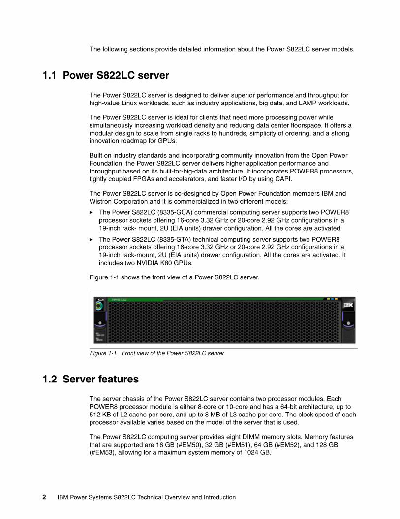
� The Power S822LC (8335-GCA) commercial computing server supports two POWER8 processor sockets offering 16-core 3.32 GHz or 20-core 2.92 GHz configurations in a 19-inch rack- mount, 2U (EIA units) drawer configuration. All the cores are activated.
� The Power S822LC (8335-GTA) technical computing server supports two POWER8 processor sockets offering 16-core 3.32 GHz or 20-core 2.92 GHz configurations in a 19-inch rack-mount, 2U (EIA units) drawer configuration. All the cores are activated. It includes two NVIDIA K80 GPUs.
Figure 1-1 shows the front view of a Power S822LC server.
Figure 1-1 Front view of the Power S822LC server
1.2 Server features
The server chassis of the Power S822LC server contains two processor modules. Each POWER8 processor module is either 8-core or 10-core and has a 64-bit architecture, up to 512 KB of L2 cache per core, and up to 8 MB of L3 cache per core. The clock speed of each processor available varies based on the model of the server that is used.
The Power S822LC computing server provides eight DIMM memory slots. Memory features that are supported are 16 GB (#EM50), 32 GB (#EM51), 64 GB (#EM52), and 128 GB (#EM53), allowing for a maximum system memory of 1024 GB.
2 IBM Power Systems S822LC Technical Overview and Introduction
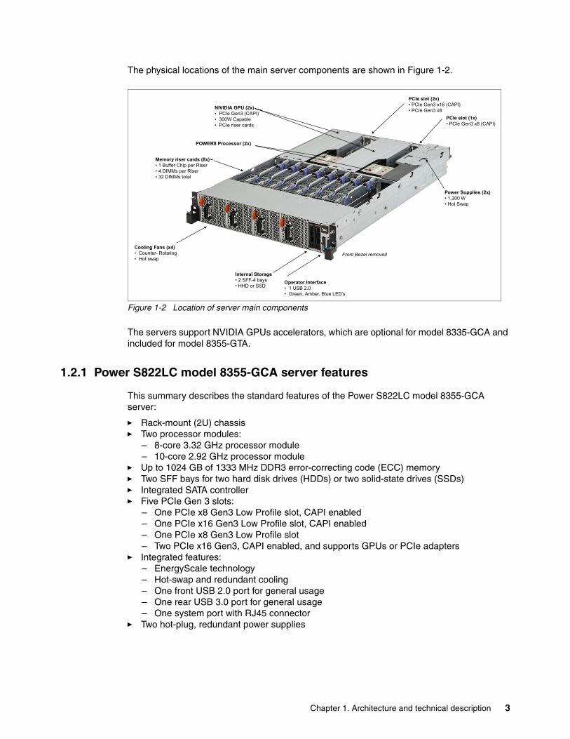
The physical locations of the main server components are shown in Figure 1-2.
Figure 1-2 Location of server main components
The servers support NVIDIA GPUs accelerators, which are optional for model 8335-GCA and included for model 8355-GTA.
1.2.1 Power S822LC model 8355-GCA server features
This summary describes the standard features of the Power S822LC model 8355-GCA server:
� Rack-mount (2U) chassis� Two processor modules:
– 8-core 3.32 GHz processor module– 10-core 2.92 GHz processor module
� Up to 1024 GB of 1333 MHz DDR3 error-correcting code (ECC) memory� Two SFF bays for two hard disk drives (HDDs) or two solid-state drives (SSDs)� Integrated SATA controller� Five PCIe Gen 3 slots:
– One PCIe x8 Gen3 Low Profile slot, CAPI enabled– One PCIe x16 Gen3 Low Profile slot, CAPI enabled– One PCIe x8 Gen3 Low Profile slot– Two PCIe x16 Gen3, CAPI enabled, and supports GPUs or PCIe adapters
� Integrated features:– EnergyScale technology– Hot-swap and redundant cooling– One front USB 2.0 port for general usage– One rear USB 3.0 port for general usage– One system port with RJ45 connector
� Two hot-plug, redundant power supplies
POWER8 Processor (2x)
Operator Interface• 1 USB 2.0• Green, Amber, Blue LED’s
Cooling Fans (x4) • Counter- Rotating• Hot swap
PCIe slot (1x)• PCIe Gen3 x8 (CAPI)
PCIe slot (2x)• PCIe Gen3 x16 (CAPI)• PCIe Gen3 x8NIVIDIA GPU (2x)
• PCIe Gen3 (CAPI)• 300W Capable• PCIe riser cards
Power Supplies (2x)• 1,300 W• Hot Swap
Memory riser cards (8x)• 1 Buffer Chip per Riser• 4 DIMMs per Riser• 32 DIMMs total
Front Bezel removed
Internal Storage• 2 SFF-4 bays• HHD or SSD
Chapter 1. Architecture and technical description 3
1.2.2 Power S822LC model 8355-GTA server features
This summary describes the standard features of the Power S822LC model 8355-GTA server:
� Rack-mount (2U) chassis� Two POWER8 processor modules:
– 8-core 3.32 GHz processor module– 10-core 2.92 GHz processor module
� Up to 1024 GB of 1333 MHz DDR3 ECC memory� Two SFF bays for two HDDs or two SSDs� Integrated SATA controller� Five PCIe Gen 3 slots:
– One PCIe x8 Gen3 Low Profile slot, CAPI enabled– One PCIe x16 Gen3 Low Profile slot, CAPI enabled– One PCIe x8 Gen3 Low Profile slot– Two PCIe x16 Gen3, CAPI enabled and dedicated to NVIDIA K80 GPU
� Two Compute Intensive Accelerator GPUs K80� Integrated features:
– EnergyScale technology– Hot-swap and redundant cooling– One front USB 2.0 port for general usage– One rear USB 3.0 port for general usage– One system port with RJ45 connector
� Two power supplies
1.2.3 Minimum features
The minimum Power S822LC model 8355-GCA server initial order must include (note that memory, disk, and adapters are not part of the minimum config, therefore must be added for the machine to be functional):
� Two processor modules (16 cores), � Two 16 GB of memory DIMMs� One LAN adapter (# EL4M) � Two HDD or SSD DASD devices� Two power supplies and power cords� An OS indicator � A rack integration indicator� A Language Group Specify
The minimum Power S822LC model 8355-GTA server initial order must include
� Two processor modules� 128 GB of memory (eight 16 GB memory DIMMs)� One LAN adapter (#EL4M)� Two Compute Intensive Accelerator GPUs K80 � Two power supplies and power cords � An OS indicator,� A rack integration indicator� A Language Group Specify
Linux is the supported OS.
4 IBM Power Systems S822LC Technical Overview and Introduction
1.3 NVIDIA Tesla GPU Accelerators
NVIDIA Tesla GPUs are massively parallel accelerators that are based on the NVIDIA Compute Unified Device Architecture (CUDA) parallel computing platform and programming model. Tesla GPUs are designed from the ground up for power-efficient, high performance computing, computational science, supercomputing, big data analytics, and machine learning applications, delivering dramatically higher acceleration than a CPU-only approach. Figure 1-3 shows a NVIDIA Tesla GPU.
Figure 1-3 NVIDIA Tesla GPU
These NVIDIA Tesla GPU Accelerators are based on the NVIDIA Kepler Architecture and designed to run the most demanding scientific models faster and more efficiently. With the introduction of Tesla K80 GPU Accelerators, you can run large scientific models on its 24 GB of GPU accelerator memory, which can process 4x larger data sets and is ideal for big data analytics. It also outperforms CPUs by up to 10x with its GPU Boost feature, which converts power headroom into user-controlled performance boost. Table 1-1 shows a summary of its characteristics.
Table 1-1 NVIDIA Tesla K80 specifications
Features Tesla K80
Number and type of GPUs 2 Kepler GK210 GPUs
Peak double precision floating point performance 1.87 Tflops
Peak single precision floating point performance 5.60 Tflops
Memory bandwidth (error correction code (ECC) off) 480 GBps
Chapter 1. Architecture and technical description 5
Among it is main characteristics, it is relevant to cite the following items:
� GPU Boost
Dynamically scales clocks, based on characteristics of the workload, for maximum application performance. This feature ensures that each application runs at the highest clocks while remaining within the power and thermal envelope.
� Zero-power Idle
Increase data center energy efficiency by powering down idle GPUs when running legacy non-accelerated workloads.
� Memory Protection
ECC memory protection for both internal memories and external GDDR5 DRAM meets a critical requirement for computing accuracy and reliability.
For more information about the NVIDIA Tesla GPU, see the NVIDIA Tesla K80 data sheet, found at:
http://www.nvidia.com/object/tesla-servers.html
When present, GPUs are installed horizontally on PCIe Gen3 slots through a provided mounting kit. Figure 1-4 shows a diagram of a GPU mounting kit, and Figure 1-5 on page 7 shows a picture of an installed GPU.
Figure 1-4 GPU installation location example
Memory size (GDDR5) 24 GB
CUDA cores 4,992
Features Tesla K80
x16 PCIe connector to planar
GPU mounting hardware
GPU
Power cable, docks to backplane
6 IBM Power Systems S822LC Technical Overview and Introduction
Figure 1-5 Picture of an installed GPU
The NVIDIA Tesla K80 GPU requires CUDA Version 7.5 and it is supported only on Linux bare metal configurations.
1.3.1 NVIDIA Compute Unified Device Architecture
NVIDIA CUDA is a parallel computing platform and programming model that enables dramatic increases in computing performance by harnessing the power of the GPU.
Today, the CUDA infrastructure is growing rapidly as more companies provide world-class tools, services, and solutions. If you want to start harnessing the performance of GPUs, the CUDA Toolkit provides a comprehensive development environment for C and C++ developers.
The easiest way to start is to use the plug-in scientific and math libraries that are available in the CUDA Toolkit to accelerate quickly common linear algebra, signal and image processing, and other common operations, such as random number generation and sorting. If you want to write your own code, the Toolkit includes a compiler, and debugging and profiling tools. You also find code samples, programming guides, user manuals, API references, and other documentation to help you get started.
The CUDA Toolkit is available at no charge. Learning to use CUDA is convenient, with comprehensive online training available, and other resources, such as webinars and books. Over 400 universities and colleges teach CUDA programming, including dozens of CUDA Centers of Excellence and CUDA Research and Training Centers. Solutions for Fortran, C#, Python, and other languages are available.
Explore the GPU Computing Ecosystem on CUDA Zone to learn more at the following website:
https://developer.nvidia.com/cuda-tools-ecosystem
Chapter 1. Architecture and technical description 7
The production release of CUDA V7.5 for POWER8 (and any subsequent release) is available for download at the following website:
https://developer.nvidia.com/cuda-downloads
1.4 Operating system support
Power S822LC (8335-GTA and 8335-GCA) servers support Linux, which provides a UNIX like implementation across many computer architectures.
For more information about the software that is available on Power Systems, see the Linux on Power Systems website:
http://www.ibm.com/systems/power/software/linux/index.html
1.5 Linux operating system
The Linux operating system is an open source, cross-platform OS. It is supported on every Power Systems server IBM sells. Linux on Power Systems is the only Linux infrastructure that offers both scale-out and scale-up choices.
1.5.1 Ubuntu
Ubuntu Server 14.04.03 LTS for IBM POWER8 is supported on the Power S822LC (8335-GCA and 8335-GTA) server as well as in a KVM Vm on the 8335-GCA.
For more information about Ubuntu Server for Ubuntu for POWER8, see the following website:
http://www.ubuntu.com/download/server/power8
1.5.2 Red Hat
Red Hat Enterprise Linux (ppc64le) Version 7.2-7.x is supported on the Power S822LC (8335-GCA and 8335-GTA) server as well as in a KVM VM on the 8335-GCA.
For additional questions about this release and supported Power Systems servers, consult the Red Hat Hardware Catalog, found at the following website:
https://hardware.redhat.com
1.5.3 Additional information
For more information about the IBM PowerLinux™ Community, see the following website:
https://www.ibm.com/developerworks/group/tpl
For more information about the features and external devices that are supported by Linux, see the following website:
http://www.ibm.com/systems/power/software/linux/index.html
8 IBM Power Systems S822LC Technical Overview and Introduction
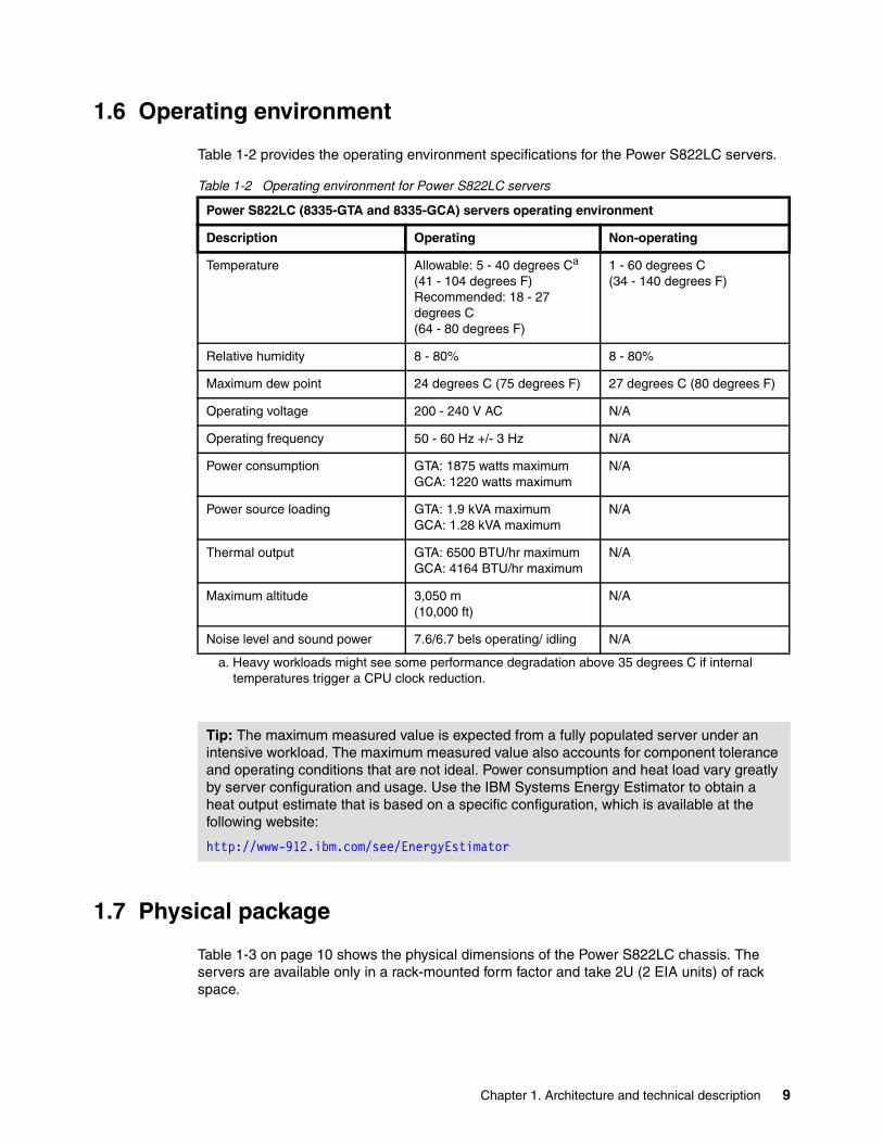
1.6 Operating environment
Table 1-2 provides the operating environment specifications for the Power S822LC servers.
Table 1-2 Operating environment for Power S822LC servers
1.7 Physical package
Table 1-3 on page 10 shows the physical dimensions of the Power S822LC chassis. The servers are available only in a rack-mounted form factor and take 2U (2 EIA units) of rack space.
Power S822LC (8335-GTA and 8335-GCA) servers operating environment
Description Operating Non-operating
Temperature Allowable: 5 - 40 degrees Ca (41 - 104 degrees F)Recommended: 18 - 27 degrees C(64 - 80 degrees F)
a. Heavy workloads might see some performance degradation above 35 degrees C if internal temperatures trigger a CPU clock reduction.
1 - 60 degrees C (34 - 140 degrees F)
Relative humidity 8 - 80% 8 - 80%
Maximum dew point 24 degrees C (75 degrees F) 27 degrees C (80 degrees F)
Operating voltage 200 - 240 V AC N/A
Operating frequency 50 - 60 Hz +/- 3 Hz N/A
Power consumption GTA: 1875 watts maximumGCA: 1220 watts maximum
N/A
Power source loading GTA: 1.9 kVA maximumGCA: 1.28 kVA maximum
N/A
Thermal output GTA: 6500 BTU/hr maximumGCA: 4164 BTU/hr maximum
N/A
Maximum altitude 3,050 m(10,000 ft)
N/A
Noise level and sound power 7.6/6.7 bels operating/ idling N/A
Tip: The maximum measured value is expected from a fully populated server under an intensive workload. The maximum measured value also accounts for component tolerance and operating conditions that are not ideal. Power consumption and heat load vary greatly by server configuration and usage. Use the IBM Systems Energy Estimator to obtain a heat output estimate that is based on a specific configuration, which is available at the following website:
http://www-912.ibm.com/see/EnergyEstimator
Chapter 1. Architecture and technical description 9
Table 1-3 Physical dimensions for the Power S822LC servers
1.8 System architecture
This section describes the overall system architecture for the Power S822LC computing servers. The bandwidths that are provided throughout the section are theoretical maximums that are used for reference.
The speeds that are shown are at an individual component level. Multiple components and application implementation are key to achieving the preferred performance. Always do the performance sizing at the application workload environment level and evaluate performance by using real-world performance measurements and production workloads.
The Power S822LC server is a two-socket system. Each socket is attached to four memory riser cards that have buffer chips for the L4 Cache and four memory RDIMM slots. The server has a maximum capacity of 32 memory DIMMs when all the memory riser cards are populated, which allows for up to 1024 GB of memory.
The servers have a total of five PCIe Gen3 slots with four of these slots being CAPI-capable, with two capable of supporting GPUs up to 300 W each.
An integrated SATA controller is on the main system board and allows for up to two SATA HDDs or SSDs to be installed.
Dimension Power S822LC (8335-GTA and 8335-GCA) servers
Width 441.5 mm (17.4 in.)
Depth 822 mm (32.4 in.)
Height 86 mm (3.4 in.)
Weight (maximum configuration) 25 kg (56 lbs.)
10 IBM Power Systems S822LC Technical Overview and Introduction
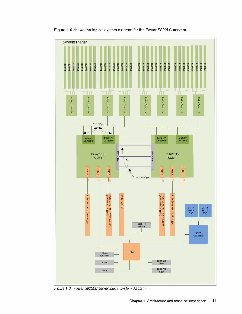
Figure 1-6 shows the logical system diagram for the Power S822LC servers.
Figure 1-6 Power S822LC server logical system diagram
Bu
ffer Ca
che L4
RD
IMM
RD
IMM
RD
IMM
RD
IMM
Bu
f fer Cach
e L4
RD
IMM
RD
IMM
RD
IMM
RD
IMM
Buffer C
ache L
4
RD
IMM
RD
IMM
RD
IMM
RD
IMM
Buffe
r Cache
L4
RD
IMM
RD
IMM
RD
IMM
RD
IMM
Buffe
r Cache
L4
RD
IMM
RD
IMM
RD
IMM
RD
IMM
Buffe
r Ca
che L4
RD
IMM
RD
IMM
RD
IMM
RD
IMM
Buffe
r Ca
che L4
RD
IMM
RD
IMM
RD
IMM
RD
IMM
Bu
ff er Ca
che L
4
RD
IMM
RD
IMM
RD
IMM
RD
IMM
SM
P A
Bu
s
PH
B 2
PH
B 1
PH
B 0
SM
P A
Bus
Memory Controller
PH
B 0
PH
B 1
PH
B 2
PC
I e G
en3 x1
6 -C
AP
I sup
port
(300W
GP
U su
pport)
PC
Ie Ge
n3 x16 -
CA
PI sup
port(30
0W
GP
U supp
ort)
PC
Ie Gen
3 x16
-C
AP
I support
PC
Ie Gen 3 x8 -
CA
PI supp
ort
PC
I e G
en3 x8
SATAController
SFF-4HDD/SSD
USB 3.0Front
USB 2.0Rear
VGA
Serial
1Gbps Ethernet
System Planar
12.8 GBps
28.8 GBps
x16
x16
x8x8 x8x8
USB 1.1Internal
POWER8SCM0
POWER8SCM1
SFF-4HDD/SSD
PLX
Memory Controller
Memory Controller
Memory Controller
Chapter 1. Architecture and technical description 11
1.9 The POWER8 processor
This section introduces the latest processor in the Power Systems product family and describes its main characteristics and features in general.
1.9.1 POWER8 processor overview
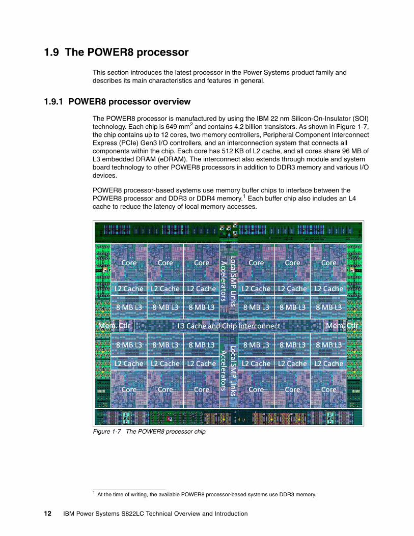
The POWER8 processor is manufactured by using the IBM 22 nm Silicon-On-Insulator (SOI) technology. Each chip is 649 mm2 and contains 4.2 billion transistors. As shown in Figure 1-7, the chip contains up to 12 cores, two memory controllers, Peripheral Component Interconnect Express (PCIe) Gen3 I/O controllers, and an interconnection system that connects all components within the chip. Each core has 512 KB of L2 cache, and all cores share 96 MB of L3 embedded DRAM (eDRAM). The interconnect also extends through module and system board technology to other POWER8 processors in addition to DDR3 memory and various I/O devices.
POWER8 processor-based systems use memory buffer chips to interface between the POWER8 processor and DDR3 or DDR4 memory.1 Each buffer chip also includes an L4 cache to reduce the latency of local memory accesses.
Figure 1-7 The POWER8 processor chip
1 At the time of writing, the available POWER8 processor-based systems use DDR3 memory.
12 IBM Power Systems S822LC Technical Overview and Introduction
The POWER8 processor is for system offerings from single-socket servers to multi-socket Enterprise servers. It incorporates a triple-scope broadcast coherence protocol over local and global SMP links to provide superior scaling attributes. Multiple-scope coherence protocols reduce the amount of SMP link bandwidth that is required by attempting operations on a limited scope (single chip or multi-chip group) when possible. If the operation cannot complete coherently, the operation is reissued by using a larger scope to complete the operation.
Here are additional features that can augment the performance of the POWER8 processor:
� Support for DDR3 and DDR4 memory through memory buffer chips that offload the memory support from the POWER8 memory controller.
� An L4 cache within the memory buffer chip that reduces the memory latency for local access to memory behind the buffer chip; the operation of the L4 cache is not apparent to applications running on the POWER8 processor. Up to 128 MB of L4 cache can be available for each POWER8 processor.
� Hardware transactional memory.
� On-chip accelerators, including on-chip encryption, compression, and random number generation accelerators.
� CAPI, which allows accelerators that are plugged into a PCIe slot to access the processor bus by using a low latency, high-speed protocol interface.
� Adaptive power management.
Table 1-4 summarizes the technology characteristics of the POWER8 processor.
Table 1-4 Summary of POWER8 processor technology
Technology POWER8 processor
Die size 649 mm2
Fabrication technology � 22 nm lithography� Copper interconnect� SOI� eDRAM
Maximum processor cores 12
Maximum execution threads core/chip 8/96
Maximum L2 cache core/chip 512 KB/6 MB
Maximum On-chip L3 cache core/chip 8 MB/96 MB
Maximum L4 cache per chip 128 MB
Maximum memory controllers 2
SMP design-point 16 sockets with POWER8 processors
Compatibility With prior generation of IBM POWER® processors
Chapter 1. Architecture and technical description 13
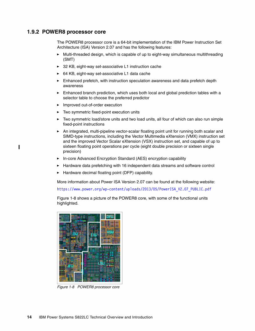
1.9.2 POWER8 processor core
The POWER8 processor core is a 64-bit implementation of the IBM Power Instruction Set Architecture (ISA) Version 2.07 and has the following features:
� Multi-threaded design, which is capable of up to eight-way simultaneous multithreading (SMT)
� 32 KB, eight-way set-associative L1 instruction cache
� 64 KB, eight-way set-associative L1 data cache
� Enhanced prefetch, with instruction speculation awareness and data prefetch depth awareness
� Enhanced branch prediction, which uses both local and global prediction tables with a selector table to choose the preferred predictor
� Improved out-of-order execution
� Two symmetric fixed-point execution units
� Two symmetric load/store units and two load units, all four of which can also run simple fixed-point instructions
� An integrated, multi-pipeline vector-scalar floating point unit for running both scalar and SIMD-type instructions, including the Vector Multimedia eXtension (VMX) instruction set and the improved Vector Scalar eXtension (VSX) instruction set, and capable of up to sixteen floating point operations per cycle (eight double precision or sixteen single precision)
� In-core Advanced Encryption Standard (AES) encryption capability
� Hardware data prefetching with 16 independent data streams and software control
� Hardware decimal floating point (DFP) capability.
More information about Power ISA Version 2.07 can be found at the following website:
https://www.power.org/wp-content/uploads/2013/05/PowerISA_V2.07_PUBLIC.pdf
Figure 1-8 shows a picture of the POWER8 core, with some of the functional units highlighted.
Figure 1-8 POWER8 processor core
14 IBM Power Systems S822LC Technical Overview and Introduction
1.9.3 Simultaneous multithreading
POWER8 processor advancements in multi-core and multi-thread scaling are remarkable. A significant performance opportunity comes from parallelizing workloads to enable the full potential of the microprocessor, and the large memory bandwidth. Application scaling is influenced by both multi-core and multi-thread technology.
SMT allows a single physical processor core to dispatch simultaneously instructions from more than one hardware thread context. With SMT, each POWER8 core can present eight hardware threads. Because there are multiple hardware threads per physical processor core, additional instructions can run at the same time. SMT is primarily beneficial in commercial environments where the speed of an individual transaction is not as critical as the total number of transactions that are performed. SMT typically increases the throughput of workloads with large or frequently changing working sets, such as database servers and web servers.
Table 1-5 shows a comparison between the different POWER processors options for a Power S822LC server and the number of threads that are supported by each SMT mode.
Table 1-5 SMT levels that are supported by a Power S822LC server
The architecture of the POWER8 processor, with its larger caches, larger cache bandwidth, and faster memory, allows threads to have faster access to memory resources, which translates into a more efficient usage of threads. Therefore, POWER8 allows more threads per core to run concurrently, increasing the total throughput of the processor and of the system.
1.9.4 Memory access
On the Power S822LC server, each POWER8 module has two memory controllers, each connected to two memory channels. Each memory channel operates at 1600 MHz and connects to a memory riser card. Each memory riser card has a memory buffer that is responsible for many functions that were previously on the memory controller, such as scheduling logic and energy management. The memory buffer also has 16 MB of L4 cache. Also, the memory riser card houses four industry-standard RDIMMs.
Each memory channel can address up to 64 GB. Therefore, the Power S822LC server can address up to 1 TB of total memory.
Cores per system SMT mode Hardware threads per system
16 Single Thread (ST) 16
16 SMT2 32
16 SMT4 64
16 SMT8 128
20 Single Thread (ST) 20
20 SMT2 40
20 SMT4 80
20 SMT8 160
Chapter 1. Architecture and technical description 15
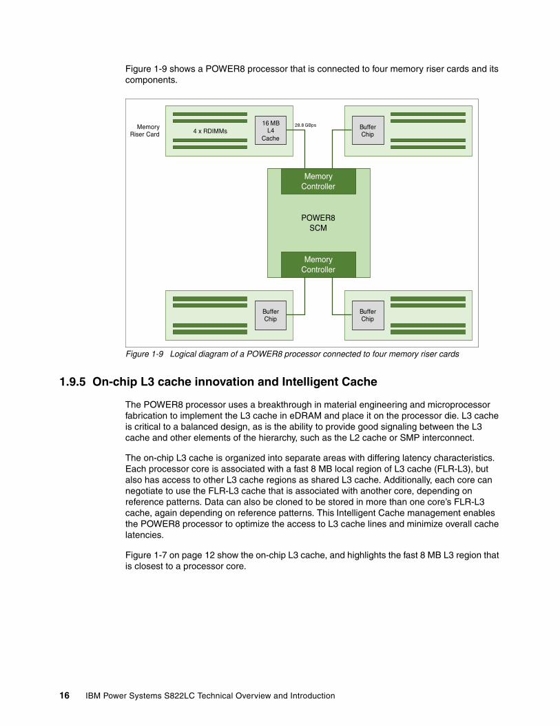
Figure 1-9 shows a POWER8 processor that is connected to four memory riser cards and its components.
Figure 1-9 Logical diagram of a POWER8 processor connected to four memory riser cards
1.9.5 On-chip L3 cache innovation and Intelligent Cache
The POWER8 processor uses a breakthrough in material engineering and microprocessor fabrication to implement the L3 cache in eDRAM and place it on the processor die. L3 cache is critical to a balanced design, as is the ability to provide good signaling between the L3 cache and other elements of the hierarchy, such as the L2 cache or SMP interconnect.
The on-chip L3 cache is organized into separate areas with differing latency characteristics. Each processor core is associated with a fast 8 MB local region of L3 cache (FLR-L3), but also has access to other L3 cache regions as shared L3 cache. Additionally, each core can negotiate to use the FLR-L3 cache that is associated with another core, depending on reference patterns. Data can also be cloned to be stored in more than one core’s FLR-L3 cache, again depending on reference patterns. This Intelligent Cache management enables the POWER8 processor to optimize the access to L3 cache lines and minimize overall cache latencies.
Figure 1-7 on page 12 show the on-chip L3 cache, and highlights the fast 8 MB L3 region that is closest to a processor core.
POWER8SCM
MemoryController
MemoryController
BufferChip
BufferChip
BufferChip
16 MBL4
Cache
MemoryRiser Card 4 x RDIMMs
28.8 GBps
16 IBM Power Systems S822LC Technical Overview and Introduction
The innovation of using eDRAM on the POWER8 processor die is significant for several reasons:
� Latency improvement
A six-to-one latency improvement occurs by moving the L3 cache on-chip compared to L3 accesses on an external (on-ceramic) Application Specific Integrated Circuit (ASIC).
� Bandwidth improvement
A 2x bandwidth improvement occurs with on-chip interconnect. Frequency and bus sizes are increased to and from each core.
� No off-chip driver or receivers
Removing drivers or receivers from the L3 access path lowers interface requirements, conserves energy, and lowers latency.
� Small physical footprint
The performance of eDRAM when implemented on-chip is similar to conventional SRAM but requires far less physical space. IBM on-chip eDRAM uses only a third of the components that conventional SRAM uses, which has a minimum of six transistors to implement a 1-bit memory cell.
� Low energy consumption
The on-chip eDRAM uses only 20% of the standby power of SRAM.
1.9.6 L4 cache and memory buffer
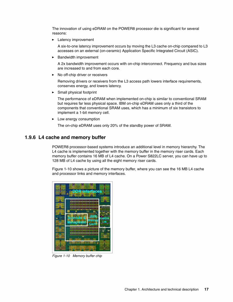
POWER8 processor-based systems introduce an additional level in memory hierarchy. The L4 cache is implemented together with the memory buffer in the memory riser cards. Each memory buffer contains 16 MB of L4 cache. On a Power S822LC server, you can have up to 128 MB of L4 cache by using all the eight memory riser cards.
Figure 1-10 shows a picture of the memory buffer, where you can see the 16 MB L4 cache and processor links and memory interfaces.
Figure 1-10 Memory buffer chip
Chapter 1. Architecture and technical description 17
Table 1-6 shows a comparison of the different levels of cache in the IBM POWER7®, IBM POWER7+™, and POWER8 processors.
Table 1-6 POWER8 cache hierarchy
1.9.7 Hardware transactional memory
Transactional memory is an alternative to lock-based synchronization. It attempts to simplify parallel programming by grouping read and write operations and running them as a single operation. Transactional memory is like database transactions, where all shared memory accesses and their effects are either committed all together or discarded as a group. All threads can enter the critical region simultaneously. If there are conflicts in accessing the shared memory data, threads try accessing the shared memory data again or are stopped without updating the shared memory data. Therefore, transactional memory is also called a lock-free synchronization. Transactional memory can be a competitive alternative to lock-based synchronization.
Transactional memory provides a programming model that makes parallel programming easier. A programmer delimits regions of code that access shared data and the hardware runs these regions atomically and in isolation, buffering the results of individual instructions, and trying execution again if isolation is violated. Generally, transactional memory allows programs to use a programming style that is close to coarse-grained locking to achieve performance that is close to fine-grained locking.
Most implementations of transactional memory are based on software. The POWER8 processor-based systems provide a hardware-based implementation of transactional memory that is more efficient than the software implementations and requires no interaction with the processor core, therefore allowing the system to operate in maximum performance.
1.9.8 Coherent Accelerator Processor Interface
Coherent Accelerator Processor Interface (CAPI) defines a coherent accelerator interface structure for attaching special processing devices to the POWER8 processor bus.
Cache POWER7 POWER7+ POWER8
L1 instruction cache: Capacity/associativity
32 KB, 4-way 32 KB, 4-way 32 KB, 8-way
L1 data cache: Capacity/associativitybandwidth
32 KB, 8-wayTwo 16 B reads or one 16 B writes per cycle
32 KB, 8-wayTwo 16 B reads or one 16 B writes per cycle
64 KB, 8-wayFour 16 B reads or one 16 B writes per cycle
L2 cache: Capacity/associativitybandwidth
256 KB, 8-wayPrivate 32 B reads and 16 B writes per cycle
256 KB, 8-wayPrivate 32 B reads and 16 B writes per cycle
512 KB, 8-way Private 64 B reads and 16 B writes per cycle
L3 cache: Capacity/associativitybandwidth
On-Chip4 MB/core, 8-way16 B reads and 16 B writes per cycle
On-Chip10 MB/core, 8-way16 B reads and 16 B writes per cycle
On-Chip8 MB/core, 8-way32 B reads and 32 B writes per cycle
L4 cache:Capacity/associativitybandwidth
N/A N/A Off-Chip16 MB/buffer chip, 16-wayUp to 8 buffer chips per socket
18 IBM Power Systems S822LC Technical Overview and Introduction
The CAPI can attach accelerators that have coherent shared memory access with the processors in the server and share full virtual address translation with these processors, which use a standard PCIe Gen3 bus.
Applications can have customized functions in FPGAs and enqueue work requests directly in shared memory queues to the FPGA, and by using the same effective addresses (pointers) it uses for any of its threads running on a host processor. From a practical perspective, CAPI allows a specialized hardware accelerator to be seen as an additional processor in the system, with access to the main system memory, and coherent communication with other processors in the system.
The benefits of using CAPI include the ability to access shared memory blocks directly from the accelerator, perform memory transfers directly between the accelerator and processor cache, and reduce the code path length between the adapter and the processors. This is possibly because the adapter is not operating as a traditional I/O device, and there is no device driver layer to perform processing. It also presents a simpler programming model.
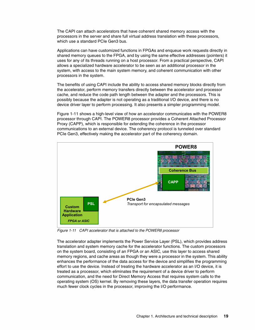
Figure 1-11 shows a high-level view of how an accelerator communicates with the POWER8 processor through CAPI. The POWER8 processor provides a Coherent Attached Processor Proxy (CAPP), which is responsible for extending the coherence in the processor communications to an external device. The coherency protocol is tunneled over standard PCIe Gen3, effectively making the accelerator part of the coherency domain.
Figure 1-11 CAPI accelerator that is attached to the POWER8 processor
The accelerator adapter implements the Power Service Layer (PSL), which provides address translation and system memory cache for the accelerator functions. The custom processors on the system board, consisting of an FPGA or an ASIC, use this layer to access shared memory regions, and cache areas as though they were a processor in the system. This ability enhances the performance of the data access for the device and simplifies the programming effort to use the device. Instead of treating the hardware accelerator as an I/O device, it is treated as a processor, which eliminates the requirement of a device driver to perform communication, and the need for Direct Memory Access that requires system calls to the operating system (OS) kernel. By removing these layers, the data transfer operation requires much fewer clock cycles in the processor, improving the I/O performance.
CustomHardware
Application
CAPP
Coherence Bus
PSL
FPGA or ASIC
POWER8
PCIe Gen3Transport for encapsulated messages
Chapter 1. Architecture and technical description 19
The implementation of CAPI on the POWER8 processor allows hardware companies to develop solutions for specific application demands and use the performance of the POWER8 processor for general applications and the custom acceleration of specific functions by using a hardware accelerator, with a simplified programming model and efficient communication with the processor and memory resources.
For a list of supported CAPI adapters, see 1.15.5, “CAPI adapters” on page 30.
1.10 Memory subsystem
The Power S822LC server is a two-socket system that supports two POWER8 SCM processor modules. The server supports a maximum of 32 DDR3 RDIMMs slots housed in eight memory riser cards.
Memory features equate to a riser card with four memory DIMMs. Memory feature codes that are supported are 16 GB, 32 GB, 64 GB, and 128 GB, and run at speeds of 1333 MHz, allowing for a maximum system memory of 1024 GB.
1.10.1 Memory riser cards
Memory riser cards are designed to house up to four industry-standard DRAM memory DIMMs and include a set of components that allow for higher bandwidth and lower latency communications:
� Memory Scheduler� Memory Management (RAS Decisions & Energy Management)� Buffer Cache
By adopting this architecture, several decisions and processes regarding memory optimizations are run outside the processor, saving bandwidth and allowing for faster processor to memory communications. It also allows for more robust reliability, availability, and serviceability (RAS). For more information about RAS, see Chapter 3, “Reliability, availability, and serviceability” on page 43.
20 IBM Power Systems S822LC Technical Overview and Introduction
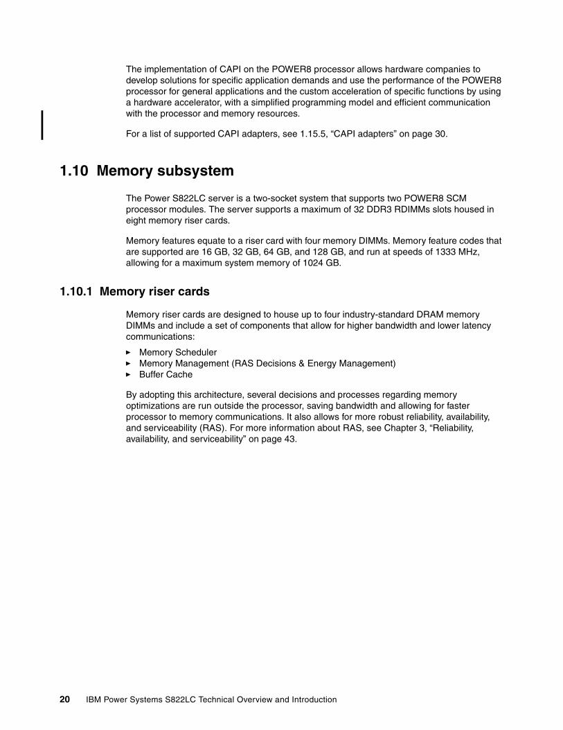
A detailed diagram of the memory riser card that is available for the Power S822LC server and its location on the server are shown in Figure 1-12.
Figure 1-12 Memory riser card components and server location
The buffer cache is a L4 cache and is built on eDRAM technology (same as the L3 cache), which has lower latency than regular SRAM. Each memory riser card has a buffer chip with 16 MB of L4 cache, and a fully populated Power S822LC server (two processors and eight memory riser cards) has 128 MB of L4 cache. The L4 cache performs several functions that have a direct impact on performance and brings a series of benefits for the Power S822LC server:
� Reduces energy consumption by reducing the number of memory requests.
� Increases memory write performance by acting as a cache and by grouping several random writes into larger transactions.
� Partial write operations that target the same cache block are “gathered” within the L4 cache before written to memory, becoming a single write operation.
� Reduces latency on memory access. Memory access for cached blocks has up to 55% lower latency than non-cached blocks.
1.10.2 Memory placement rules
Each feature code equates to a riser card with four memory DIMMs.
The following memory feature codes are orderable:
� 16 GB DDR3: A riser card with four 4 GB 1333 MHz DDR3 DRAMs (#EM50)� 32 GB DDR3: A riser card with four 8 GB 1333 MHz DDR3 DRAMs (#EM51)� 64 GB DDR3: A riser card with four 16 GB 1333 MHz DDR3 DRAMs (#EM52)� 128 GB DDR3: A riser card with four 32 GB 1333 MHz DDR3 DRAMs (#EM53)
Connection to system backplane
DDR3 DIMM (4x)
Memory Buffer
Chapter 1. Architecture and technical description 21
The supported maximum memory is 1024 GB by installing a quantity of eight #EM53 components.
For the Power S822LC model 8335-GCA server:
� A minimum of two memory features is required.� Base memory is 32 GB with two 16 GB 1333 MHz DDR3 memory modules (#EM50). � Memory features cannot be mixed.� Valid quantities for memory features are two, four, and eight.
Memory upgrades must have the same capacity as the initial memory. Then, account for any plans for future memory upgrades when you decide which memory feature size to use at the time of the initial system order. Table 1-7 shows the supported quantities for each memory feature.
Table 1-7 Supported quantity of feature codes for model 8335-GCA
For the Power S822LC model 8335-GTA server:
� It is required that all the memory modules be populated.
� Memory features cannot be mixed.
� The base memory is 128 GB with eight 16 GB, 1333 MHz DDR3 memory modules (#EM50).
� Memory upgrades are not supported.
Table 1-8 shows the supported quantities for each memory feature code.
Table 1-8 Supported quantity of feature codes for model 8335-GTA
The required approach is to install memory evenly across all processors in the system. Balancing memory across the installed processors allows memory access in a consistent manner and typically results in the best possible performance for your configuration. Account for any plans for future memory upgrades when you decide which memory feature size to use at the time of the initial system order.
Total installed memory
Memory features 32 GB 64 GB 128 GB 256 GB 512 GB 1024 GB
16 GB (#EM50) 2 4 8
32 GB (#EM51) 2 4 8
64 GB (#EM52) 2 4 8
128 GB (#EM53) 8
Total installed memory
Memory features 32 GB 64 GB 128 GB 256 GB 512 GB 1024 GB
16 GB (#EM50) 8
32 GB (#EM51) 8
64 GB (#EM52) 8
128 GB (#EM53) 8
22 IBM Power Systems S822LC Technical Overview and Introduction
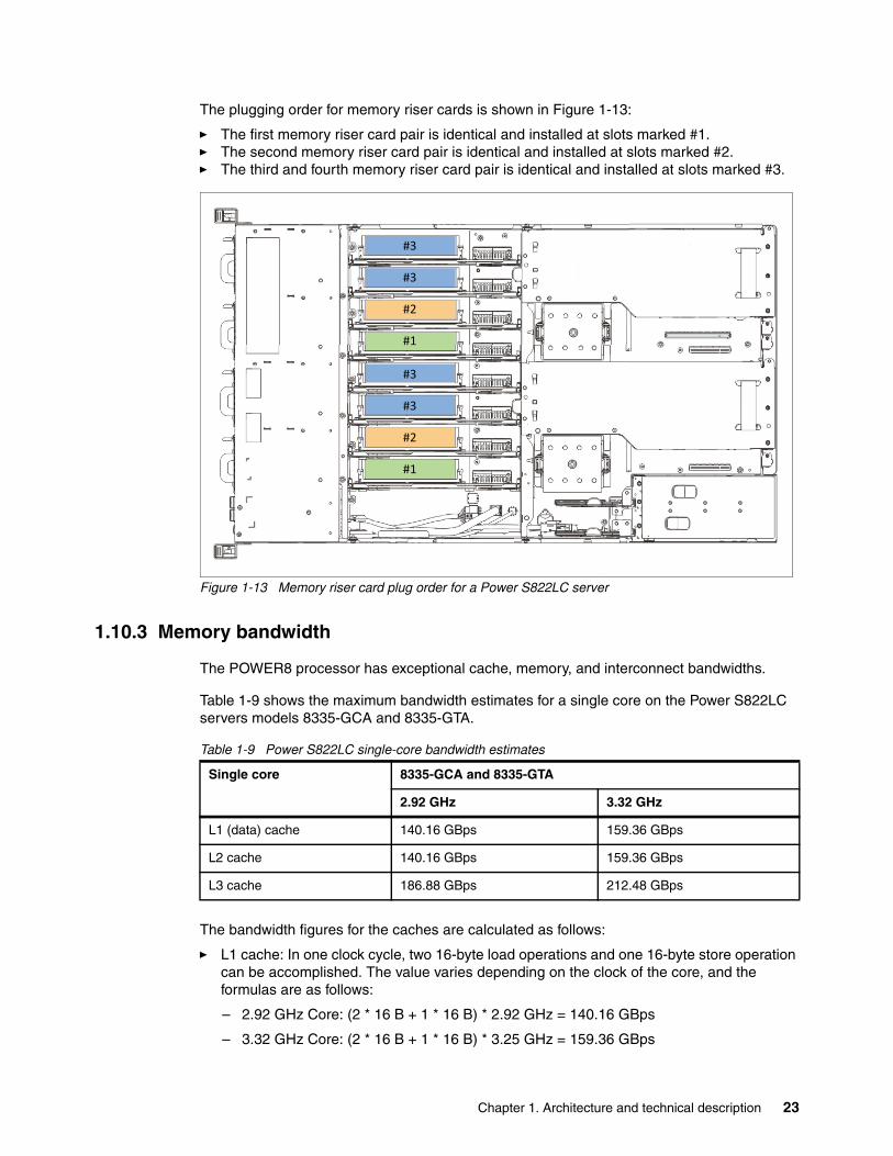
The plugging order for memory riser cards is shown in Figure 1-13:
� The first memory riser card pair is identical and installed at slots marked #1.� The second memory riser card pair is identical and installed at slots marked #2.� The third and fourth memory riser card pair is identical and installed at slots marked #3.
Figure 1-13 Memory riser card plug order for a Power S822LC server
1.10.3 Memory bandwidth
The POWER8 processor has exceptional cache, memory, and interconnect bandwidths.
Table 1-9 shows the maximum bandwidth estimates for a single core on the Power S822LC servers models 8335-GCA and 8335-GTA.
Table 1-9 Power S822LC single-core bandwidth estimates
The bandwidth figures for the caches are calculated as follows:
� L1 cache: In one clock cycle, two 16-byte load operations and one 16-byte store operation can be accomplished. The value varies depending on the clock of the core, and the formulas are as follows:
– 2.92 GHz Core: (2 * 16 B + 1 * 16 B) * 2.92 GHz = 140.16 GBps
– 3.32 GHz Core: (2 * 16 B + 1 * 16 B) * 3.25 GHz = 159.36 GBps
��
��
��
��
��
��
��
��
Single core 8335-GCA and 8335-GTA
2.92 GHz 3.32 GHz
L1 (data) cache 140.16 GBps 159.36 GBps
L2 cache 140.16 GBps 159.36 GBps
L3 cache 186.88 GBps 212.48 GBps
Chapter 1. Architecture and technical description 23
� L2 cache: In one clock cycle, one 32-byte load operation and one 16-byte store operation can be accomplished. The value varies depending on the clock of the core, and the formula is as follows:
– 2.92 GHz Core: (1 * 32 B + 1 * 16 B) * 2.92 GHz = 140.16 GBps
– 3.32 GHz Core: (1 * 32 B + 1 * 16 B) * 3.25 GHz = 159.36 GBps
� L3 cache: One 32-byte load operation and one 32-byte store operation can be accomplished at half-clock speed, and the formula is as follows:
– 2.92 GHz Core: (1 * 32 B + 1 * 32 B) * 2.92 GHz = 186.88 GBps
– 3.32 GHz Core: (1 * 32 B + 1 * 32 B) * 3.25 GHz = 212.48 GBps
For the entire Power S822LC server populated with the two processor modules, the overall bandwidths are shown in Table 1-10.
Table 1-10 Power S822LC server - total bandwidth estimates
Where:
� Total memory bandwidth: Each POWER8 processor has four memory channels running at 9.6 GBps capable of reading 2 bytes and writing 1 byte at a time. The bandwidth formula is calculated as follows:
Four channels * 9.6 GBps * 3 bytes = 192 GBps per processor module
� SMP interconnect: The POWER8 processor has two 2-byte 3-lane A buses working at 6.4 GHz. Each A bus has three active lanes. The bandwidth formula is calculated as follows:
3 A buses * 2 bytes * 6.4 GHz = 38.4 GBps
� PCIe Interconnect: Each POWER8 processor has 32 PCIe lanes running at 8 Gbps full-duplex. The bandwidth formula is calculated as follows:
Thirty-two lanes * 2 processors * 8 Gbps * 2 = 128 GBps
1.11 System bus
This section provides more information about the internal buses.
The Power S822LC servers have internal I/O connectivity through Peripheral Component Interconnect Express Gen3 (PCI Express Gen3 or PCIe Gen3) slots.
Total bandwidths 8335-GCA and 8335-GTA
20 cores @ 2.92 GHz 16 cores @ 3.32 GHz
L1 (data) cache 2,803 GBps 2,550 GBps
L2 cache 2,803 GBps 2,550 GBps
L3 cache 3,738 GBps 3,400 GBps
Total memory 230 GBps 230 GBps
SMP interconnect 38.4 GBps 38.4 GBps
PCIe interconnect 128 GBps 128 GBps
24 IBM Power Systems S822LC Technical Overview and Introduction
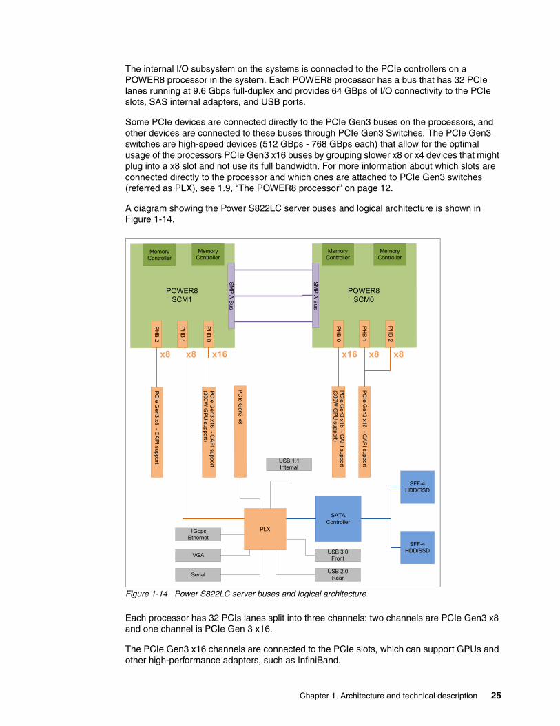
The internal I/O subsystem on the systems is connected to the PCIe controllers on a POWER8 processor in the system. Each POWER8 processor has a bus that has 32 PCIe lanes running at 9.6 Gbps full-duplex and provides 64 GBps of I/O connectivity to the PCIe slots, SAS internal adapters, and USB ports.
Some PCIe devices are connected directly to the PCIe Gen3 buses on the processors, and other devices are connected to these buses through PCIe Gen3 Switches. The PCIe Gen3 switches are high-speed devices (512 GBps - 768 GBps each) that allow for the optimal usage of the processors PCIe Gen3 x16 buses by grouping slower x8 or x4 devices that might plug into a x8 slot and not use its full bandwidth. For more information about which slots are connected directly to the processor and which ones are attached to PCIe Gen3 switches (referred as PLX), see 1.9, “The POWER8 processor” on page 12.
A diagram showing the Power S822LC server buses and logical architecture is shown in Figure 1-14.
Figure 1-14 Power S822LC server buses and logical architecture
Each processor has 32 PCIs lanes split into three channels: two channels are PCIe Gen3 x8 and one channel is PCIe Gen 3 x16.
The PCIe Gen3 x16 channels are connected to the PCIe slots, which can support GPUs and other high-performance adapters, such as InfiniBand.
SM
P A
Bu
s
PH
B 2
PH
B 1
PH
B 0
SM
P A
Bu
s
Memory Controller
PH
B 0
PH
B 1
PH
B 2
PC
Ie G
en3 x 1
6 -C
AP
I suppo
rt(3
00W
GP
U sup
port)
PC
Ie Ge
n3 x16 -C
AP
I support
(300
W G
PU
suppo
rt)
PC
Ie Ge
n3 x16 -
CA
PI supp
ort
PC
Ie Ge
n3 x8 -
CA
PI su
pport
PC
Ie G
e n3 x8
SATAController
SFF-4HDD/SSD
USB 3.0Front
USB 2.0Rear
VGA
Serial
1Gbps Ethernet
x16x8x8
USB 1.1Internal
POWER8SCM0
POWER8SCM1
SFF-4HDD/SSD
PLX
Memory Controller
Memory Controller
Memory Controller
x16 x8x8
Chapter 1. Architecture and technical description 25
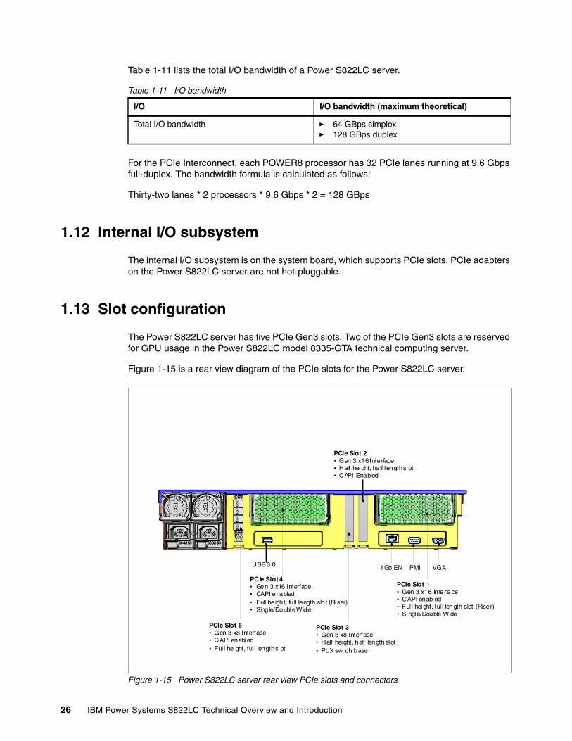
Table 1-11 lists the total I/O bandwidth of a Power S822LC server.
Table 1-11 I/O bandwidth
For the PCIe Interconnect, each POWER8 processor has 32 PCIe lanes running at 9.6 Gbps full-duplex. The bandwidth formula is calculated as follows:
Thirty-two lanes * 2 processors * 9.6 Gbps * 2 = 128 GBps
1.12 Internal I/O subsystem
The internal I/O subsystem is on the system board, which supports PCIe slots. PCIe adapters on the Power S822LC server are not hot-pluggable.
1.13 Slot configuration
The Power S822LC server has five PCIe Gen3 slots. Two of the PCIe Gen3 slots are reserved for GPU usage in the Power S822LC model 8335-GTA technical computing server.
Figure 1-15 is a rear view diagram of the PCIe slots for the Power S822LC server.
Figure 1-15 Power S822LC server rear view PCIe slots and connectors
I/O I/O bandwidth (maximum theoretical)
Total I/O bandwidth � 64 GBps simplex� 128 GBps duplex
IBM Conf ident ial
PCIe Slot 5• Gen 3 x8 Interface• CAPI enabled• Ful l height, ful l length slot
PCIe Slot 4• Gen 3 x16 Interface• CAPI enabled• Full he ight, fu ll length slo t (Riser)• Sing le/Double Wide
PCIe Slot 3• Gen 3 x8 Interface• Half height, half length slot• PLX swi tch base
PCIe Slot 1• Gen 3 x16 In terface• CAPI enabled• Ful l height, ful l length slot (Riser)• Single/Double Wide
PCIe Slot 2• Gen 3 x16 Interface• Half height, ha lf length slot• CAPI Enabled
USB 3.0 1Gb EN IPMI VGA
26 IBM Power Systems S822LC Technical Overview and Introduction
Table 1-12 shows the PCIe Gen3 slot configuration for the Power S822LC server.
Table 1-12 Power S822LC server PCIe slot properties
The two x16 slots that are provided by the internal PCIe riser (Slot 1 and Slot 4) can be populated with GPU adapters (NVIDIA) or can be used for any high-profile (not LP) adapters. Mixing of GPU and other high-profile adapters on the internal PCIe riser is supported.
Only LP adapters can be placed in LP slots. An x8 adapter can be placed in an x16 slot, but an x16 adapter cannot be placed in an x8 slot. One LP slot must be used for a required Ethernet adapter (#5260, #EL3Z, or #EN0T).
1.14 System ports
The system board has one 1 Gbps Ethernet port, one Intelligent Platform Management Interface (IPMI) port and a VGA port, as shown in Figure 1-15 on page 26.
The integrated system ports are supported for modem and asynchronous terminal connections with Linux. Any other application that uses serial ports requires a serial port adapter to be installed in a PCI slot. The integrated system ports do not support IBM PowerHA® configurations. The VGA port does not support cable lengths that exceed 3 meters.
Slot Description Card size CAPI capable
Power limit
Slot 5b PCIe Gen3 x8 Half height,half length
Yes 50 W
Slot 4a
a. This slot is made available through a PCIe riser. It can be filled with a PCIe gen3 graphics processing unit (GPU) aadapter (#EC49) or a full-height, full-length adapter in the 8335-GCA. Mixing a GPU and standard adapter is not supported. In The 8335-GTA, a GPU must be installed.
PCIe Gen3 x16 Full height,full length
Yes 300 W (GPU)75 W (Full height full length adapters)
Slot 3b
b. This is an x8 slot. The priority for this slot is high-performance adapters followed by any other adapter.
PCIe Gen3 x8 Half height,half length
No 50 W
Slot 2 PCIe Gen3 x16 Half height,half length
Yes 75 W
Slot 1a PCIe Gen3 x16 Full height,full length
Yes 300 W (GPU)75 W (Full height full length adapters)
Chapter 1. Architecture and technical description 27
1.15 PCI adapters
This section covers the various types and functions of the PCI adapters that are supported by the Power S822LC servers.
1.15.1 PCI Express
Peripheral Component Interconnect Express (PCIe) uses a serial interface and allows for point-to-point interconnections between devices (by using a directly wired interface between these connection points). A single PCIe serial link is a dual-simplex connection that uses two pairs of wires, one pair for transmit and one pair for receive, and can transmit only one bit per cycle. These two pairs of wires are called a lane. A PCIe link can consist of multiple lanes. In these configurations, the connection is labeled as x1, x2, x8, x12, x16, or x32, where the number is effectively the number of lanes.
The PCIe interfaces that are supported on this server are PCIe Gen3, which are capable of 16 GBps simplex (32 GBps duplex) on a single x16 interface. PCIe Gen3 slots also support previous generation (Gen2 and Gen1) adapters, which operate at lower speeds, according to the following rules:
� Place x1, x4, x8, and x16 speed adapters in the same size connector slots first, before mixing adapter speed with connector slot size.
� Adapters with lower speeds are allowed in larger sized PCIe connectors, but larger speed adapters are not compatible in smaller connector sizes (that is, a x16 adapter cannot go in an x8 PCIe slot connector).
PCIe adapters use a different type of slot than PCI adapters. If you attempt to force an adapter into the wrong type of slot, you might damage the adapter or the slot.
POWER8 based servers can support two different form factors of PCIe adapters:
� PCIe low profile (LP) cards, which are used with the Power S822L server.
� PCIe full height and full high cards are designed for the 4 EIA scale-out servers, such as the Power S824L server.
Before adding or rearranging adapters, use the System Planning Tool to validate the new adapter configuration. For more information, see the System Planning Tool website:
http://www.ibm.com/systems/support/tools/systemplanningtool/
If you are installing a new feature, ensure that you have the software that is required to support the new feature and determine whether there are any existing update prerequisites to install. To obtain this information, use the IBM prerequisite website:
https://www-912.ibm.com/e_dir/eServerPreReq.nsf
The following sections describe the supported adapters and provide tables of orderable feature code numbers.
1.15.2 LAN adapters
To connect the Power S822LC servers to a local area network (LAN), you can use the LAN adapters that are supported in the PCIe slots of the system unit. Table 1-13 on page 29 lists the supported local area network (LAN) adapters for the Power S822LC servers.
28 IBM Power Systems S822LC Technical Overview and Introduction
Table 1-13 Supported LAN adapters)
1.15.3 Compute Intensive Accelerator
Compute Intensive Accelerators are GPUs that are developed by NVIDIA. With NVIDIA GPUs, the Power S822LC serve can offload processor-intensive operations to a GPU accelerator and boost performance. The Power S822LC server aims to deliver a new class of technology that maximizes performance and efficiency for all types of scientific, engineering, Java, big data analytics, and other technical computing workloads.
Table 1-14 lists the available Compute Intensive Accelerators.
Table 1-14 Graphics processing units adapters that are supported
Feature code
CCIN Description GCA/GTA support
Max OS support
5260 576F PCIe2 LP 4-port 1 GbE Adapter GCA and GTA 3 Linux
5899 576F PCIe2 4-port 1 GbE Adapter GCA 2 Linux
EC3A 57BD PCIe3 LP 2-Port 40 GbE NIC RoCE QSFP+ Adapter
GCA and GTA 2 Linux
EC3B 57BD PCIe3 2-Port 40 GbE NIC RoCE QSFP+ Adapter
GCA 2 Linux
EC3E 2CEA PCIe3 LP 2-port 100Gb EDR InfiniBand Adapter x16
GCA and GTA 1 Linux
EC3T 2CEB PCIe3 LP 1-port 100Gb EDR InfiniBand Adapter x16
GCA and GTA 1 Linux
EL3Z PCIe2 LP 2-port 10/1 GbE BaseT RJ45 Adapter
GCA and GTA 3 Linux
EL4L PCIe2 x4 LP capable 4-port (UTP) 1GbE Adapter
GCA 2 Linux
EL4M PCIe2 x4 LP 4-port (UTP) 1GbE Adapter
GCA and GTA 3 Linux
EL55 PCIe2 2-port 10/1 GbE BaseT RJ45 Adapter
GCA 2 Linux
EN0S 2CC3 PCIe2 4-Port (10Gb+1 GbE) SR+RJ45 Adapter
GCA 2 Linux
EN0T PCIe2 LP 4-Port (10Gb+1 GbE) SR+RJ45 Adapter
GCA and GTA 3 Linux
Feature code
Description GCA/GTA support
Max OS support
EC49 Compute Intensive Accelerator GPU K80 GCA and GTA 2 Linux
Chapter 1. Architecture and technical description 29
1.15.4 Fibre Channel adapters
The servers support direct or SAN connection to devices that use Fibre Channel adapters. Table 1-15 summarizes the available Fibre Channel adapters, which all have LC connectors.
If you are attaching a device or switch with an SC type fiber connector, then an LC-SC 50 Micron Fibre Converter Cable (#2456) or an LC-SC 62.5 Micron Fibre Converter Cable (#2459) is required.
Table 1-15 Fibre Channel adapters supported
1.15.5 CAPI adapters
The available CAPI adapters are shown in Table 1-16.
Table 1-16 Available CAPI adapters
This CAPI FPGA (Field Programmable Gate Array) adapter acts as a co-processor for the POWER8 processor chip handling specialized, repetitive function extremely efficiently. The adapter is preloaded with a GZIP application and is intended to run as a gzip accelerator. The GZIP application maximum bandwidth is a PCIe Gen3 interface bandwidth.
#EJ1B and #EJ1A are electronically identical with the same CCIN of 2CF0. #EJ1B has a low profile tail stock and #EJ1A has a high profile tail stock.
Requires firmware version 810.32, or higher.
1.15.6 Flash storage adapters
The available flash storage adapters are shown in Table 1-17.
Table 1-17 Available flash storage adapters
Feature code
CCIN Description GCA/GTA support
Max OS support
EL43 577F PCIe3 LP 16Gb 2-port Fibre Channel Adapter
GCA and GTA 2 Linux
EL5B 577F PCIe3 16Gb 2-port Fibre Channel Adapter
GCA 2 Linux
Feature code
CCIN Description GCA/GTA support
Max OS support
EJ1A 2CF0 CAPI Compression Accelerator Adapter GCA 2 Linux
EJ1B 2CF0 CAPI Compression Accelerator Adapter LP
GCA and GTA 2 Linux
Feature code
CCIN Description GCA/GTA support
Max OS support
EC54 58CB PCIe3 1.6TB NVMe Flash Adapter GCA 3 Linux
EC56 58CC PCIe3 3.2TB NVMe Flash Adapter GCA 3 Linux
30 IBM Power Systems S822LC Technical Overview and Introduction
1.16 Internal storage
The internal storage on the Power S822LC server contains the following features:
� A storage backplane for two 2.5-inch SFF Gen4 SATA HDDs or SDDs.
� One integrated SATA disk controller without RAID capability.
� The storage split backplane feature is not supported.
Table 1-18 presents a summarized view of these features.
Table 1-18 Summary of features for the integrated SATA disk controller
The 2.5-inch or small form factor (SFF) SAS bays can contain SATA drives (HDD or SSD) that are mounted on a Gen4 tray or carrier (also knows as SFF-4). SFF-2 or SFF-3 drives do not fit in an SFF-4 bay. All SFF-4 bays support concurrent maintenance or hot-plug capability.
Figure 1-16 shows the server front view with the standard backplane.
Figure 1-16 Server front view with SFF-4 locations
Limitation: The disks use an SFF-4 carrier. Disks that are used in other Power Systems usually have SFF-3 or SFF-2 carrier and are not compatible with this system.
Option Integrated SATA disk controller
Supported RAID types JBOD
Disk bays Two SFF Gen4 (HDDs/SDDs)
SATA controllers Single
IBM Easy Tier® capable controllers
No
External SAS ports No
Split backplane No
SFF-4 CarrierSATA HDD or SSD
SFF-4 CarrierSATA HDD or SSD
Front bezel is removed in this illustration
Chapter 1. Architecture and technical description 31
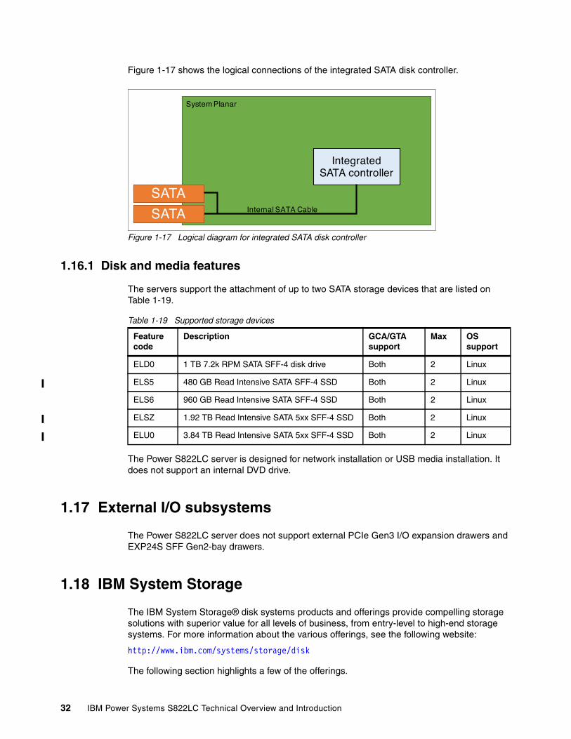
Figure 1-17 shows the logical connections of the integrated SATA disk controller.
Figure 1-17 Logical diagram for integrated SATA disk controller
1.16.1 Disk and media features
The servers support the attachment of up to two SATA storage devices that are listed on Table 1-19.
Table 1-19 Supported storage devices
The Power S822LC server is designed for network installation or USB media installation. It does not support an internal DVD drive.
1.17 External I/O subsystems
The Power S822LC server does not support external PCIe Gen3 I/O expansion drawers and EXP24S SFF Gen2-bay drawers.
1.18 IBM System Storage
The IBM System Storage® disk systems products and offerings provide compelling storage solutions with superior value for all levels of business, from entry-level to high-end storage systems. For more information about the various offerings, see the following website:
http://www.ibm.com/systems/storage/disk
The following section highlights a few of the offerings.
IntegratedSATA controller
Internal SATA Cable
SATA
SATA
System Planar
Feature code
Description GCA/GTA support
Max OS support
ELD0 1 TB 7.2k RPM SATA SFF-4 disk drive Both 2 Linux
ELS5 480 GB Read Intensive SATA SFF-4 SSD Both 2 Linux
ELS6 960 GB Read Intensive SATA SFF-4 SSD Both 2 Linux
ELSZ 1.92 TB Read Intensive SATA 5xx SFF-4 SSD Both 2 Linux
ELU0 3.84 TB Read Intensive SATA 5xx SFF-4 SSD Both 2 Linux
32 IBM Power Systems S822LC Technical Overview and Introduction
IBM Network Attached Storage IBM Network Attached Storage (NAS) products provide a wide-range of network attachment capabilities to a broad range of host and client systems, such as IBM Scale Out Network Attached Storage and the IBM System Storage N series. For more information about the hardware and software, see the following website:
http://www.ibm.com/systems/storage/network
IBM Storwize familyThe IBM Storwize® family is the ideal solution to optimize the data architecture for business flexibility and data storage efficiency. Different models, such as the IBM Storwize V3700, IBM Storwize V5000, and IBM Storwize V7000, offer storage virtualization, IBM Real-time Compression™, Easy Tier, and many more functions. For more information, see the following website:
http://www.ibm.com/systems/storage/storwize
IBM FlashSystem familyThe IBM FlashSystem™ family delivers extreme performance to derive measurable economic value across the data architecture (servers, software, applications, and storage). IBM offers a comprehensive flash portfolio with the IBM FlashSystem family. For more information, see the following website:
http://www.ibm.com/systems/storage/flash
IBM XIV Storage SystemThe IBM XIV® Storage System is a high-end disk storage system, helping thousands of enterprises meet the challenge of data growth with hotspot-free performance and ease of use. Simple scaling, high service levels for dynamic, heterogeneous workloads, and tight integration with hypervisors and the OpenStack platform enable optimal storage agility for cloud environments.
XIV Storage Systems extend ease of use with integrated management for large and multi-site XIV deployments, reducing operational complexity and enhancing capacity planning. For more information, see the following website:
http://www.ibm.com/systems/storage/disk/xiv/index.html
IBM System Storage DS8000The IBM System Storage DS8800 storage system is a high-performance, high-capacity, and secure storage system that delivers the highest levels of performance, flexibility, scalability, resiliency, and total overall value for the most demanding, heterogeneous storage environments. The storage system can manage a broad scope of storage workloads that exist in today’s complex data center, doing it effectively and efficiently.
Additionally, the IBM System Storage DS8000® storage system includes a range of features that automate performance optimization and application quality of service, and also provide the highest levels of reliability and system uptime. For more information, see the following website:
http://www.ibm.com/systems/storage/disk/ds8000/index.html
Chapter 1. Architecture and technical description 33
1.19 Java
When running Java applications on the POWER8 processor, the pre-packaged Java that is part of a Linux distribution is designed to meet the most common requirements.
If you require a different level of Java, there are several resources available.
Current information about IBM Java and tested Linux distributions are available here:
https://www.ibm.com/developerworks/java/jdk/linux/tested.html
Additional information about the OpenJDK port for Linux on PPC64 LE, as well as some pre-generated builds can be found here:
http://cr.openjdk.java.net/~simonis/ppc-aix-port/
Launchpad.net has resources for Ubuntu builds. You can find out about them here:
https://launchpad.net/ubuntu/+source/openjdk-9https://launchpad.net/ubuntu/+source/openjdk-8https://launchpad.net/ubuntu/+source/openjdk-7
34 IBM Power Systems S822LC Technical Overview and Introduction
Chapter 2. Management and virtualization
As you look for ways to maximize the return on your IT infrastructure investments, virtualizing workloads becomes an attractive proposition.
The IBM Power Systems S822LC (8335-GCA) server is excellent for clients that want the advantages of running their big data, Java, open source, and industry applications on a platform designed and optimized for data and Linux.
This chapter attempts to identify and clarify the tools that are available for managing Linux on Power Systems servers.
2
Note: There is no virtualization for the 8335-GTA, only Open Power Application Layer (OPAL) Bare Metal (EC16).
© Copyright IBM Corp. 2015. All rights reserved. 35
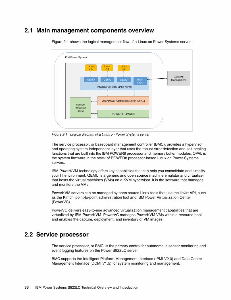
2.1 Main management components overview
Figure 2-1 shows the logical management flow of a Linux on Power Systems server.
Figure 2-1 Logical diagram of a Linux on Power Systems server
The service processor, or baseboard management controller (BMC), provides a hypervisor and operating system-independent layer that uses the robust error detection and self-healing functions that are built into the IBM POWER8 processor and memory buffer modules. OPAL is the system firmware in the stack of POWER8 processor-based Linux on Power Systems servers.
IBM PowerKVM technology offers key capabilities that can help you consolidate and simplify your IT environment. QEMU is a generic and open source machine emulator and virtualizer that hosts the virtual machines (VMs) on a KVM hypervisor. It is the software that manages and monitors the VMs.
PowerKVM servers can be managed by open source Linux tools that use the libvirt API, such as the Kimchi point-to-point administration tool and IBM Power Virtualization Center (PowerVC).
PowerVC delivers easy-to-use advanced virtualization management capabilities that are virtualized by IBM PowerKVM. PowerVC manages PowerKVM VMs within a resource pool and enables the capture, deployment, and inventory of VM images.
2.2 Service processor
The service processor, or BMC, is the primary control for autonomous sensor monitoring and event logging features on the Power S822LC server.
BMC supports the Intelligent Platform Management Interface (IPMI V2.0) and Data Center Management Interface (DCMI V1.5) for system monitoring and management.
���������� ��
������������
��������� �����������������
���!"���� ��#����$%�!�&
&��'���
"����(��)(��)
���$%�
��
���$%�
��
�'��
��� ��
���*
�� ���
����+���(��)
���$%�
��
36 IBM Power Systems S822LC Technical Overview and Introduction
BMC monitors the operation of the firmware during the boot process and also monitors the hypervisor for termination. The firmware code update is supported through the BMC and IPMI interfaces.
2.2.1 Open Power Abstraction Layer
On PowerKVM systems, the OPAL firmware provides a hypervisor interface to the underlying hardware. OPAL firmware allows PowerKVM to use the VirtIO API. The VirtIO API specifies an independent interface between VMs and the service processor.
The VirtIO API is a high-performance API that para-virtualized devices use to gain speed and efficiency. VirtIO para-virtualized devices are especially useful for guest operating systems that run I/O heavy tasks and applications.
For the 8335-GCA, OPAL Bare Metal (EC16) or OPAL with PowerKVM 3.1(EC40) are the system firmware in the stack of POWER8 processor-based servers. For the 8335-GTA, only the OPAL Bare Metal (EC16) is available.
For more information about OPAL skiboot, go to the following website:
https://github.com/open-power/skiboot
2.2.2 Intelligent Platform Management Interface
The IPMI is an open standard for monitoring, logging, recovery, inventory, and control of hardware that is implemented independent of the main CPU, BIOS, and OS. It is the default console to use when you configure PowerKVM. The Power S822LC server provides one 10M/100M baseT IPMI port.
The ipmitool is a utility for managing and configuring devices that support IPMI. It provides a simple command-line interface (CLI) to the service processor. You can install the ipmitool from the Linux distribution packages in your workstation or another server (preferably on the same network as the installed server). For example, in Ubuntu, run the following command:
$ sudo apt-get install ipmitool
To connect to your system with IPMI, you must know the IP address of the server and have a valid password. To power on the server with ipmitool, complete the following steps:
1. Open a terminal program.
2. Power on your server by running the following command:
ipmitool -I lanplus -H fsp_ip_address -P ipmi_password power on
3. Activate your IPMI console by running the following command:
ipmitool -I lanplus -H fsp_ip_address -P ipmi_password sol activate
For more help with configuring IBM PowerKVM on a Linux on Power Systems server, see the following website:
https://www.ibm.com/support/knowledgecenter/linuxonibm/liabp/liabpusingipmi.htm
Also, see the Quick Start Guide for Configuring IBM PowerKVM on Power Systems, found at:
https://www.ibm.com/support/knowledgecenter/api/content/nl/en-us/linuxonibm/liabq/kvmquickstart_guide.pdf
Chapter 2. Management and virtualization 37
2.2.3 Petitboot bootloader
Petitboot is a kexec-based bootloader that is used by POWER8 processor-based systems that are configured with PowerKVM.
After the POWER8 processor-based system powers on, the petitboot bootloader scans local boot devices and network interfaces to find boot options that are available to the system. Petitboot returns a list of boot options that are available to the system.
If you are using a static IP or if you did not provide boot arguments in your network boot server, you must provide the details to petitboot. You can configure petitboot to find your boot server by following the instructions found at:
https://www.ibm.com/support/knowledgecenter/linuxonibm/liabp/liabppetitbootadvanced.htm
You can edit petitboot configuration options, change the amount of time before Petitboot automatically boots, and so on, by following the instructions found at:
https://www.ibm.com/support/knowledgecenter/linuxonibm/liabp/liabppetitbootconfig.htm
After you select to start the PowerKVM installer, the installer wizard walks you through the steps to set up disk options, your root password, time zones, and so on.
You can read more about the petitboot bootloader program at the following website:
https://www.kernel.org/pub/linux/kernel/people/geoff/petitboot/petitboot.html
2.3 IBM PowerKVM
Kernel-based Virtual Machine (KVM) is a cross-platform, open source hypervisor that provides enterprise-class performance, scalability, and security to run Linux and other workloads on a range of processor architectures. For the Linux scale-out systems with POWER8 technology, this mechanism is ported to Power Systems and is called IBM PowerKVM (5765-KVM).
For more information about PowerKVM, see IBM PowerKVM Configuration and Use, SG24-8231.
PowerKVM supports Big Endian (BE) and Little Endian (LE) mode.
Table 2-1 lists the supported Linux distributions as a PowerKVM guest VM on the Power S822LC server.
Table 2-1 Linux support on PowerKVM
System PowerKVM
Power S822LCserver (8335-GCA)
Big Endian (BE) and Little Endian (LE): Ubuntu 14.04.03 LTS
Note: Power S822LC (8335-GCA) and PowerKVM do not support AIX or IBM i guest VMs and cannot be managed by an HMC.
38 IBM Power Systems S822LC Technical Overview and Introduction
IBM intends to continue working with Red Hat to support the Power S822LC server with an upcoming Red Hat Enterprise Linux 7 release. For additional questions about the availability of this release and supported Power Systems, consult the Red Hat Hardware Catalog at the following website:
https://hardware.redhat.com
For a complete list of supported virtualization options for Linux on Power Systems servers, go to the following website:
http://www.ibm.com/support/knowledgecenter/linuxonibm/liaam/liaamvirtoptions.htm
2.3.1 Downloading PowerKVM
If your system is not pre-configured with PowerKVM, you need to download the installer file. PowerKVM installation files are available from the Entitled System Support website, found at:
http://www.ibm.com/servers/eserver/ess/index.wss
2.3.2 Updating PowerKVM
If you want to update your system with the latest PowerKVM package, you can find the updates through Fix Central or the IBM yum repository for PowerKVM. If your system has Internet access, you can use Kimchi or yum. If you do not have Internet access, use the ibm-update-system utility. For more information, go to the following website:
https://www.ibm.com/support/knowledgecenter/linuxonibm/liabp/liabpupdatesystem.htm
2.3.3 Upgrading PowerKVM
If you want to upgrade PowerKVM to a new release, see the publication Upgrade PowerKVM, found at:
https://www.ibm.com/support/knowledgecenter/linuxonibm/liabp/liabpupgrade.htm
2.3.4 Kimchi management tool
Kimchi is an Apache-licensed project that is hosted on GitHub. It is an HTML5-based management tool that can get you started with PowerKVM. It runs as a daemon on the hypervisor host and interfaces with underlying libvirt, QEMU, and KVM components. You use Kimchi to create and manage guests, monitor your host system, create networking interfaces, add storage, and update packages.
To use Kimchi, open a browser and point it to https://ip_address:8001, where ip_address is the IP address of your KVM system. Log in by using the admin user name and password.
Kimchi represents a simple, open source, multi-platform virtualization tool to manage PowerKVM. You can learn more about the Kimchi project at the following website:
https://github.com/kimchi-project/kimchi
Note: When you connect to Kimchi, make sure that you enable SSL connections in your browser. For Firefox browsers, you might also be required to connect to https://ip_address:64667/, where ip_address is the IP address of your host KVM system and accept the self-signed certificate. Connect by using the HTTP secure (HTTPS).
Chapter 2. Management and virtualization 39
2.4 PowerVC
The PowerVC (5765-VCS) is an advanced enterprise virtualization management offering for Power Systems based on the OpenStack technology. OpenStack is an open source software that controls large pools of server, storage, and networking resources throughout a data center. PowerVC Version 1.3.0 was announced in October 2015 and is built on OpenStack (liberty). This comprehensive virtualization management offering enables VM setup and management.
PowerVC manages the S822LC through PowerKVM. PowerKVM is supported only on the 8335-GCA.
2.4.1 Benefits
PowerVC includes the following features and benefits:
� VM image capture, deployment, resizing, and management
� Policy-based VM placement to help improve usage and reduce complexity
� Policy-based workload optimization that uses either VM migration or resource movement by using mobile capacity on demand
� VM Mobility with placement policies to help reduce the burden on IT staff in a simplified GUI
� A management system that manages existing virtualization deployments
� Integrated management of storage, network, and compute resources
For more information about hardware and operating system support for PowerVC hosts, see Hardware and Software Requirements, found at:
http://www.ibm.com/support/knowledgecenter/SSXK2N_1.2.3/com.ibm.powervc.kvm.help.doc/powervc_hwandsw_reqs_kvm.html
2.4.2 New features
PowerVC Standard Edition includes advanced policy-based management for managing PowerKVM environments, which is a new DRO component that uses policy-based control to move automatically workloads to available resources by using VM migration. This DRO component removes the need for manual rebalancing of workloads during periods of constrained CPU.
For more information about hardware and operating system support for PowerVC hosts, Hardware and Software Requirements, found at:
http://www.ibm.com/support/knowledgecenter/SSXK2N_1.2.3/com.ibm.powervc.kvm.help.doc/powervc_hwandsw_reqs_kvm.html
For more information about PowerVC and PowerKVM, see the following resources:
� Introduction to PowerVC Standard managing PowerKVM in the IBM Knowledge Center, found at:
http://www.ibm.com/support/knowledgecenter/SSXK2N_1.2.3/com.ibm.powervc.kvm.help.doc/powervc_overview_kvm.html
� IBM PowerVC Version 1.2 Introduction and Configuration
40 IBM Power Systems S822LC Technical Overview and Introduction
2.4.3 Lifecycle
With the introduction of PowerVC V1.3.0, the end of service date for PowerVC V1.2 for standard support is April 2017. For more information about the PowerVC lifecycle, see the following website:
http://www.ibm.com/systems/power/software/virtualization-management/lifecycle.html
Chapter 2. Management and virtualization 41

42 IBM Power Systems S822LC Technical Overview and Introduction
Chapter 3. Reliability, availability, and serviceability
This chapter provides information about IBM Power Systems reliability, availability, and serviceability (RAS) design and features.
The elements of RAS can be described as follows:
Reliability Indicates how infrequently a defect or fault in a server occurs
Availability Indicates how infrequently the functioning of a system or application is impacted by a fault or defect
Serviceability Indicates how well faults and their effects are communicated to system managers and how efficiently and nondisruptively the faults are repaired
3
© Copyright IBM Corp. 2015. All rights reserved. 43
3.1 Introduction
The IBM Power Systems S822LC servers are bringing POWER8 processor and memory RAS functions into a highly competitive cloud data center with open source Linux technology as an operating system and virtualization.
The Open Power Abstraction Layer (OPAL) firmware provides a hypervisor and operating system independent layer that uses the robust error-detection and self-healing functions built into the POWER8 processor and memory buffer modules.
The processor address-paths and data-paths are protected with parity or error-correcting codes (ECCs); the control logic, state machines, and computational units have sophisticated error detection. The processor core soft errors or intermittent errors are recovered with processor instruction retry. Unrecoverable errors are reported as machine check (MC) errors. Errors that affect the integrity of data lead to system checkstop.
3.1.1 RAS enhancements of POWER8 processor-based scale-out servers
The Power S822LC servers, in addition to being built on advanced RAS characteristics of the POWER8 processor, offer reliability and availability features that often are not seen in such scale-out servers.
Here is a brief summary of these features:
� Processor enhancements integration
POWER8 processor chips are implemented by using 22 nm technology, and are integrated on SOI modules.
The processor design supports a spare data lane on each fabric bus, which is used to communicate between processor modules. A spare data lane can be substituted for a failing one dynamically during system operation.
A POWER8 processor module has improved performance, including support of a maximum of 12 cores because doing more work with less hardware in a system supports greater reliability. The Power S822LC servers offer two processor socket offerings with 8-core and 10-core processor configurations. So, there are 16-core and 20-core configurations that are available.
The On Chip Controller (OCC) monitors various temperature sensors in the processor module, memory modules, and environmental temperature sensors, and steers the throttling of processor cores and memory channels if the temperature rises over thresholds that are defined by the design. The power supplies have their own independent thermal sensors and monitoring.
Power supplies and voltage regulator modules monitor Over-Voltage, Under-Voltage, and Over-Current conditions. They report to a “power good” tree that is monitored by the service processor.
� I/O subsystem
The PCIe controllers are integrated into the POWER8 processor. All the PCIe slots are directly driven by the PCIe controllers.
44 IBM Power Systems S822LC Technical Overview and Introduction
� Memory subsystem
The memory subsystem has proactive memory scrubbing to prevent accumulation of multiple single-bit errors. The ECC scheme can correct the complete failure of any one memory module within an ECC word. After marking the module as unusable, the ECC logic can still correct single-symbol (two adjacent bit) errors. An uncorrectable error of data of any layer of cache up to the main memory is marked to prevent usage of fault data. The processor’s memory controller and the memory buffer have retry capabilities for certain fetch and store faults.
3.2 IBM terminology versus x86 terminology
The different components and descriptions in the boot process have similar functions, but have different terms for POWER8 processor-based and x86-based scale-out servers. Table 3-1 shows a quick overview of the terminology.
Table 3-1 Terminology
3.3 Error handling
This section describes how the Power S822LC server handles different errors and recovery functions. It provides some general information and helps you understand some techniques.
3.3.1 Processor core/cache correctable error handling
The OPAL firmware provides a hypervisor and operating system-independent layer that uses the robust error-detection and self-healing functions that are built into the POWER8 processor and memory buffer modules.
The processor address-paths and data-paths are protected with parity or error-correction codes (ECC). The control logic, state machines, and computational units have sophisticated error detection. The processor core soft errors or intermittent errors are recovered with processor instruction retry. Unrecoverable errors are reported as an MC. Errors that affect the integrity of data lead to system checkstop.
The Level 1 (L1) data and instruction caches in each processor core are parity-protected, and data is stored through to L2 immediately. L1 caches have a retry capability for intermittent errors and a cache set delete mechanism for handling solid failures.
The L2 and L3 caches in the POWER8 processor and L4 cache in the memory buffer chip are protected with double-bit detect, single-bit correct ECC.
IBM x86 Description
SBE Undisclosed Self-Boot Engine: Starts the boot process.
Host Boot BIOS Core, Powerbus (SMP), and memory initialization.
OPAL BIOS/ VT-d / UEFI KVM hardware abstraction, PCIe RC, IODA2 (VT-d), and open firmware.
OCC PCU, off chip microprocessors
Performs real-time functions, such as power management.
HBRT N/A Correctable error monitoring and OCC monitoring.
Chapter 3. Reliability, availability, and serviceability 45
Special Uncorrectable Error handlingSpecial Uncorrectable Error (SUE) handling prevents an uncorrectable error in memory or cache from immediately causing an MC with uncorrectable error (UE). The system marks the data such that if the data ever is read again, it generates an MC with UE. Termination may be limited to the program / partition or hypervisor owning the data. If the data is referenced by an I/O adapter, it freeze if data is transferred to an I/O device.
3.3.2 Processor Instruction Retry and other try again techniques
Within the processor core, soft error events might occur that interfere with the various computation units. When such an event can be detected before a failing instruction is completed, the processor hardware might try the operation again by using the advanced RAS feature that is known as Processor Instruction Retry.
Processor Instruction Retry allows the system to recover from soft faults that otherwise result in outages of applications or the entire server. Try-again techniques are used in other parts of the system as well. Faults that are detected on the memory bus that connects processor memory controllers to DIMMs can be tried again. In POWER8 processor-based systems, the memory controller is designed with a replay buffer that allows memory transactions to be tried again after certain faults internal to the memory controller faults are detected. This function complements the try-again abilities of the memory buffer module.
3.3.3 Other processor chip functions
Within a processor chip, there are other functions besides just processor cores.
POWER8 processors have built-in accelerators that can be used as application resources to handle such functions as random number generation. POWER8 also introduces a controller for attaching cache-coherent adapters that are external to the processor module. The POWER8 design contains a function to “freeze” the function that is associated with some of these elements, without taking a system-wide checkstop. Depending on the code that uses these features, a “freeze” event might be handled without an application or partition outage.
As indicated elsewhere, single-bit errors, even solid faults, within internal or external processor fabric buses, are corrected by the ECC that is used. POWER8 processor-to-processor module fabric buses also use a spare data lane so that a single failure can be repaired without calling for the replacement of hardware.
3.4 Serviceability
The server is designed for system installation and setup, feature installation and removal, proactive maintenance, and corrective repair that is performed by the client:
� Customer Install and Setup (CSU)� Customer Feature Install (CFI)� Customer Repairable Units (CRU)
Warranty service upgrades are offered for an onsite repair (OSR) by an IBM System Services Representative (SSR), or an authorized warranty service provider.
46 IBM Power Systems S822LC Technical Overview and Introduction
3.4.1 Detection introduction
The first and most crucial component of a solid serviceability strategy is the ability to detect accurately and effectively errors when they occur.
Although not all errors are a guaranteed threat to system availability, those errors that go undetected can cause problems because the system has no opportunity to evaluate and act if necessary. POWER processor-based systems employ IBM z Systems™ server-inspired error detection mechanisms, extending from processor cores and memory to power supplies and hard disk drives (HDDs).
3.4.2 Error checkers and fault isolation registers
POWER processor-based systems contain specialized hardware detection circuitry that is used to detect erroneous hardware operations. Error-checking hardware ranges from parity error detection that is coupled with Processor Instruction Retry and bus try again, to ECC correction on caches and system buses.
Within the processor/memory subsystem error checker, error-checker signals are captured and stored in hardware FIRs. The associated logic circuitry is used to limit the domain of an error to the first checker that encounters the error. In this way, runtime error diagnostic tests can be deterministic so that for every check station, the unique error domain for that checker is defined and mapped to CRUs that can be repaired when necessary.
3.4.3 Service processor
The service processor supports the Intelligent Platform Management Interface (IPMI 2.0) and Data Center Management Interface (DCMI 1.5) for system monitoring and management. The service processor provides the following platform system functions:
� Power on/off� Power sequencing� Power fault monitoring� Power reporting� Fan/thermal control� Fault monitoring� VPD inventory collection� Serial over LAN (SOL)� Service Indicator LED management� Code update� Event reporting through System Event Logs (SELs)
All SELs can be retrieved either directly from the service processor or from the host OS (Linux). The service processor monitors the operation of the firmware during the boot process.
The firmware code update is supported through the service processor and IPMI interface. Multiple firmware images exist in the system and the backup copy is used if the primary image is corrupted and unusable.
Chapter 3. Reliability, availability, and serviceability 47
3.4.4 Diagnosing
General diagnostic objectives are to detect and identify problems so that they can be resolved quickly.
Using the extensive network of advanced and complementary error detection logic that is built directly into hardware, firmware, and operating systems, Power Systems servers can perform considerable self-diagnosis.
Host Boot IPL In POWER8, the initialization process during IPL changed. The service processor is no longer the only instance that initializes and runs the boot process. With POWER8, the service processor initializes the boot processes, but on the POWER8 processor itself, one part of the firmware is running and performing the central electrical complex chip initialization. A new component that is called the PNOR chip stores the Host Boot firmware and the SBE is an internal part of the POWER8 chip itself and is used to start the chip.
Device drivers In certain cases, diagnostic tests are preferably performed by operating system-specific drivers, most notably adapters or I/O devices that are owned directly by a logical partition. In these cases, the operating system device driver often works with I/O device Licensed Internal Code to isolate and recover from problems. Potential problems are reported to an operating system device driver, which logs the error.
3.4.5 General problem determination
Accessing the Advanced System Management GUI interface provides a general overview of sensor information and possible errors.
Using an event sensor display as a primary interface for problem determination
This function has the following aspects:
� Covers 90% of typical failures� Does not handle transient failure scenarios
Using SEL logs or operating system syslog records for remainderThis function has the following aspects:
� Sensors can be enabled/disabled by a client.� The “Get Sensor Event Enable” IPMI command is available.
SEL events: Platform-related eventsThe following platform-related events are available under the SEL events:
� SELs link to eSELs� eSEL represents a service action required event:
– SELs linked to the eSEL represent “service action required” and a part to be replaced.– You may have multiple SELs that are linked to the eSEL.– SELs not linked to eSEL may not represent a service action required event.– Without an eSEL Event, the System Attention LED does not turn on.
48 IBM Power Systems S822LC Technical Overview and Introduction
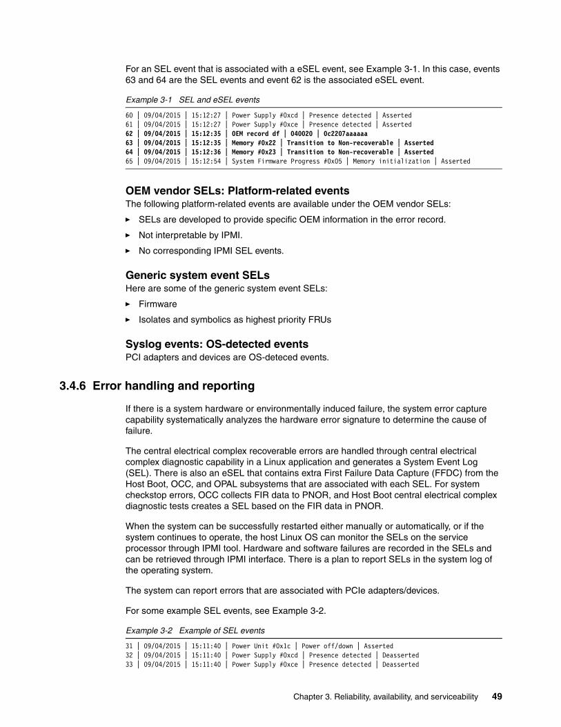
For an SEL event that is associated with a eSEL event, see Example 3-1. In this case, events 63 and 64 are the SEL events and event 62 is the associated eSEL event.
Example 3-1 SEL and eSEL events
60 | 09/04/2015 | 15:12:27 | Power Supply #0xcd | Presence detected | Asserted61 | 09/04/2015 | 15:12:27 | Power Supply #0xce | Presence detected | Asserted62 | 09/04/2015 | 15:12:35 | OEM record df | 040020 | 0c2207aaaaaa63 | 09/04/2015 | 15:12:35 | Memory #0x22 | Transition to Non-recoverable | Asserted64 | 09/04/2015 | 15:12:36 | Memory #0x23 | Transition to Non-recoverable | Asserted65 | 09/04/2015 | 15:12:54 | System Firmware Progress #0x05 | Memory initialization | Asserted
OEM vendor SELs: Platform-related eventsThe following platform-related events are available under the OEM vendor SELs:
� SELs are developed to provide specific OEM information in the error record.
� Not interpretable by IPMI.
� No corresponding IPMI SEL events.
Generic system event SELsHere are some of the generic system event SELs:
� Firmware
� Isolates and symbolics as highest priority FRUs
Syslog events: OS-detected eventsPCI adapters and devices are OS-deteced events.
3.4.6 Error handling and reporting
If there is a system hardware or environmentally induced failure, the system error capture capability systematically analyzes the hardware error signature to determine the cause of failure.
The central electrical complex recoverable errors are handled through central electrical complex diagnostic capability in a Linux application and generates a System Event Log (SEL). There is also an eSEL that contains extra First Failure Data Capture (FFDC) from the Host Boot, OCC, and OPAL subsystems that are associated with each SEL. For system checkstop errors, OCC collects FIR data to PNOR, and Host Boot central electrical complex diagnostic tests creates a SEL based on the FIR data in PNOR.
When the system can be successfully restarted either manually or automatically, or if the system continues to operate, the host Linux OS can monitor the SELs on the service processor through IPMI tool. Hardware and software failures are recorded in the SELs and can be retrieved through IPMI interface. There is a plan to report SELs in the system log of the operating system.
The system can report errors that are associated with PCIe adapters/devices.
For some example SEL events, see Example 3-2.
Example 3-2 Example of SEL events
31 | 09/04/2015 | 15:11:40 | Power Unit #0x1c | Power off/down | Asserted32 | 09/04/2015 | 15:11:40 | Power Supply #0xcd | Presence detected | Deasserted33 | 09/04/2015 | 15:11:40 | Power Supply #0xce | Presence detected | Deasserted
Chapter 3. Reliability, availability, and serviceability 49
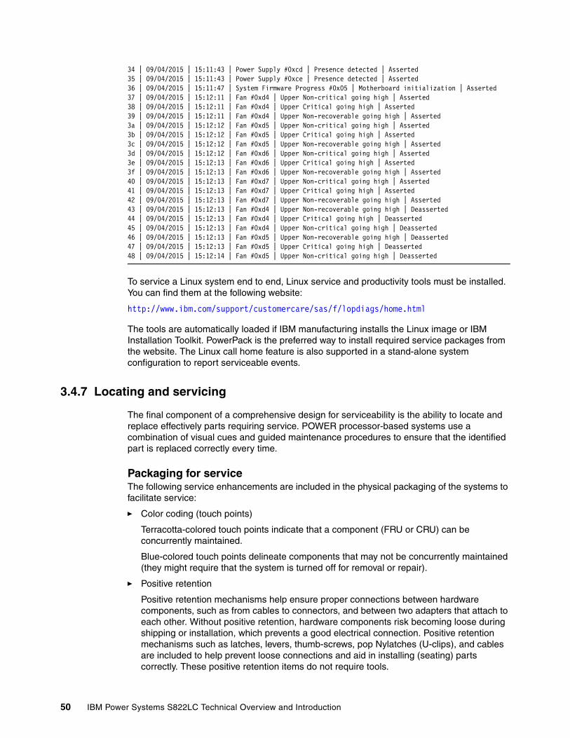
34 | 09/04/2015 | 15:11:43 | Power Supply #0xcd | Presence detected | Asserted35 | 09/04/2015 | 15:11:43 | Power Supply #0xce | Presence detected | Asserted36 | 09/04/2015 | 15:11:47 | System Firmware Progress #0x05 | Motherboard initialization | Asserted37 | 09/04/2015 | 15:12:11 | Fan #0xd4 | Upper Non-critical going high | Asserted38 | 09/04/2015 | 15:12:11 | Fan #0xd4 | Upper Critical going high | Asserted39 | 09/04/2015 | 15:12:11 | Fan #0xd4 | Upper Non-recoverable going high | Asserted3a | 09/04/2015 | 15:12:12 | Fan #0xd5 | Upper Non-critical going high | Asserted3b | 09/04/2015 | 15:12:12 | Fan #0xd5 | Upper Critical going high | Asserted3c | 09/04/2015 | 15:12:12 | Fan #0xd5 | Upper Non-recoverable going high | Asserted3d | 09/04/2015 | 15:12:12 | Fan #0xd6 | Upper Non-critical going high | Asserted3e | 09/04/2015 | 15:12:13 | Fan #0xd6 | Upper Critical going high | Asserted3f | 09/04/2015 | 15:12:13 | Fan #0xd6 | Upper Non-recoverable going high | Asserted40 | 09/04/2015 | 15:12:13 | Fan #0xd7 | Upper Non-critical going high | Asserted41 | 09/04/2015 | 15:12:13 | Fan #0xd7 | Upper Critical going high | Asserted42 | 09/04/2015 | 15:12:13 | Fan #0xd7 | Upper Non-recoverable going high | Asserted43 | 09/04/2015 | 15:12:13 | Fan #0xd4 | Upper Non-recoverable going high | Deasserted44 | 09/04/2015 | 15:12:13 | Fan #0xd4 | Upper Critical going high | Deasserted45 | 09/04/2015 | 15:12:13 | Fan #0xd4 | Upper Non-critical going high | Deasserted46 | 09/04/2015 | 15:12:13 | Fan #0xd5 | Upper Non-recoverable going high | Deasserted47 | 09/04/2015 | 15:12:13 | Fan #0xd5 | Upper Critical going high | Deasserted48 | 09/04/2015 | 15:12:14 | Fan #0xd5 | Upper Non-critical going high | Deasserted
To service a Linux system end to end, Linux service and productivity tools must be installed. You can find them at the following website:
http://www.ibm.com/support/customercare/sas/f/lopdiags/home.html
The tools are automatically loaded if IBM manufacturing installs the Linux image or IBM Installation Toolkit. PowerPack is the preferred way to install required service packages from the website. The Linux call home feature is also supported in a stand-alone system configuration to report serviceable events.
3.4.7 Locating and servicing
The final component of a comprehensive design for serviceability is the ability to locate and replace effectively parts requiring service. POWER processor-based systems use a combination of visual cues and guided maintenance procedures to ensure that the identified part is replaced correctly every time.
Packaging for service The following service enhancements are included in the physical packaging of the systems to facilitate service:
� Color coding (touch points)
Terracotta-colored touch points indicate that a component (FRU or CRU) can be concurrently maintained.
Blue-colored touch points delineate components that may not be concurrently maintained (they might require that the system is turned off for removal or repair).
� Positive retention
Positive retention mechanisms help ensure proper connections between hardware components, such as from cables to connectors, and between two adapters that attach to each other. Without positive retention, hardware components risk becoming loose during shipping or installation, which prevents a good electrical connection. Positive retention mechanisms such as latches, levers, thumb-screws, pop Nylatches (U-clips), and cables are included to help prevent loose connections and aid in installing (seating) parts correctly. These positive retention items do not require tools.
50 IBM Power Systems S822LC Technical Overview and Introduction
Service Indicator LEDsThe Service Indicator LED function is for scale-out systems, including Power Systems such as the Power S812LC server, that can be repaired by clients. In the Service Indicator LED implementation, when a fault condition is detected on the POWER8 processor-based system, an amber FRU fault LED is illuminated (turned on solid), which is then rolled up to the system fault LED.
When the ID LED button on the front panel is pressed, the blue LED on the front panel and the blue ID LED on the rear panel light up. The technical personnel can easily locate the system on the rack, disconnect cables from the system, and remove it from the rack for later repair.
The Service Indicator operator panel contains the following items:
� Power On LED (Green LED: Front)– Off: Enclosure is off.– On Solid: Enclosure is powered on.– On Blink: Enclosure is in the standby-power state.
� Enclosure Identify LED (Blue LED: Front)– Off: Normal.– On Solid: Identify state.– On Blink: Reserved.
� System Information/Attention LED (Amber LED: Front)– Off: Normal.– On Solid: System Attention State.
� Enclosure Fault Roll-up LED (Amber LED: Front)– Off: Normal.– On Solid: Fault.– Power On/Off Switch.– Pin-hole Reset Switch.– USB Port.– Beeper.– Altitude Sensor with Ambient Thermal Sensor.– VPD Module.
Concurrent maintenance The following components can be replaced without powering off the server:
� Drives in the front bay� Power supplies� Fans
The POWER8 processor-based systems are designed with the understanding that certain components have higher intrinsic failure rates than others. These components can include fans, power supplies, and physical storage devices. Other devices, such as I/O adapters, can wear from repeated plugging and unplugging. For these reasons, these devices are concurrently maintainable when properly configured. Concurrent maintenance is facilitated because of the redundant design for the power supplies and physical storage.
IBM Knowledge CenterIBM Knowledge Center provides you with a single place where you can access product documentation for IBM systems hardware, operating systems, and server software.
Chapter 3. Reliability, availability, and serviceability 51
The purpose of IBM Knowledge Center, in addition to providing client-related product information, is to provide softcopy information to diagnose and fix any problems that might occur with the system. Because the information is electronically maintained, changes because of updates or the addition of new capabilities can be used by service representatives immediately.
The IBM Knowledge Center provides the following up-to-date documentation to service effectively the system:
� Quick Install Guide� User’s Guide� Trouble Shooting Guide� Boot Configuration Guide
The documentation can be downloaded in PDF format or used online through an internet connection.
The IBM Knowledge Center can be found at:
http://www.ibm.com/support/knowledgecenter/
Supporting information for the Power S822LC (8335-GTA and 8335-GCA) servers is available online at the following websites:
� 8335-GCA:
http://www.ibm.com/support/knowledgecenter/HW4L4/p8hdx/8335_gca_landing.htm
� 8335-GTA:
http://www.ibm.com/support/knowledgecenter/HW4M4/p8hdx/8335_gta_landing.htm
Warranty and spare partsThe system comes with a 3-year warranty for parts. The replacement parts can be ordered through the Advanced Part Exchange Warranty Service, which can be found at the following website:
http://www.ibm.com/common/ssi/cgi-bin/ssialias?htmlfid=877/ENUSZG15-0194&infotype=AN&subtype=CA&appname=skmwww
3.5 Manageability
Several functions and tools help you can efficiently and effectively manage your system.
3.5.1 Service user interfaces
The service interface allows support personnel or the client to communicate with the service support applications in a server by using a console, interface, or terminal. Delivering a clear, concise view of available service applications, the service interface allows the support team to manage system resources and service information in an efficient and effective way. Applications that are available through the service interface are carefully configured and placed to give service providers access to important service functions.
52 IBM Power Systems S822LC Technical Overview and Introduction
Various service interfaces are used depending on the state of the system and its operating environment. Here are the primary service interfaces:
� Service Indicator LEDs (See “Service Indicator LEDs” on page 51 and “Concurrent maintenance” on page 51.)
� Service processor
Service InterfaceThe service interface allows the client and the support personnel to communicate with the service support applications in a server by using a browser. It delivers a clear, concise view of available service applications. The service interface allows the support client to manage system resources and service information in an efficient and effective way. Different service interfaces are used depending on the state of the system, hypervisor, and operating environment. Here are the primary service interfaces:
� Service processor: Ethernet Service Network with IPMI Version 2.0
� Service Indicator LEDs: System attention and system identification (front and back)
� Host operating system: Command-line interface (CLI)
The service processor is a controller that is running its own operating system.
3.5.2 IBM Power Systems Firmware maintenance
The IBM Power Systems Client-Managed Licensed Internal Code is a methodology that you can use to manage and install Licensed Internal Code updates on a Power Systems server and its associated I/O adapters.
Firmware updatesSystem firmware is delivered as a release level or a service pack. Release levels support the general availability (GA) of new functions or features, and new machine types or models. Upgrading to a higher release level is disruptive to customer operations. These release levels are supported by service packs. Service packs are intended to contain only firmware fixes and not introduce new functions. A service pack is an update to an existing release level.
IBM is increasing its clients’ opportunity to stay on a given release level for longer periods. Clients that want maximum stability can defer until there is a compelling reason to upgrade, such as the following reasons:
� A release level is approaching its end of service date (that is, it has been available for about a year, and soon service will not be supported).
� Move a system to a more standardized release level when there are multiple systems in an environment with similar hardware.
� A new release has a new function that is needed in the environment.
� A scheduled maintenance action causes a platform restart, which provides an opportunity to also upgrade to a new firmware release.
The updating and upgrading of system firmware depends on several factors, such as the current firmware that is installed, and what operating systems is running on the system. These scenarios and the associated installation instructions are comprehensively outlined in the firmware section of Fix Central, found at the following website:
http://www.ibm.com/support/fixcentral/
Chapter 3. Reliability, availability, and serviceability 53
3.5.3 Updating the system firmware with the ipmitool command
General firmware update steps for the Power S812LC server are managed by running the ipmitool command. Complete the following steps, but be sure that you always see the provided Firmware Release notes for the most current Installation instructions:
1. Power off the machine and install code from Standby Power state by running the following command:
ipmitool -H <hostname> -I lan -U ADMIN -P admin chassis power off
2. Issue a BMC reset (establish a stable starting point) by running the following command:
ipmitool -H <BMC IP> -I lan -U ADMIN -P admin mc reset cold
� From a companion system, run the following commands to flash the BMC and firmware:
– ipmitool -H <BMC IP> -I lanplus -U ADMIN -P admin raw 0x32 0xba 0x18 0x00 (The command protects the BMC memory content so that you do not lose the network settings.)
– ipmitool -H <BMC IP> -U ADMIN -I lanplus -P admin hpm upgrade <xxxxx.hpm> -z 30000 force
If the BMC network settings are lost, it is possible to restore them by completing the following steps:
1. Set up a serial connection to the BMC by logging in and running the following commands to set up the network:
– /usr/local/bin/ipmitool -H 127.0.0.1 -I lan -U ADMIN -P admin lan set 1 ipsrc static
– /usr/local/bin/ipmitool -H 127.0.0.1 -I lan -U ADMIN -P admin lan set 1 ipaddr x.x.x.x
– /usr/local/bin/ipmitool -H 127.0.0.1 -I lan -U ADMIN -P admin lan set 1 netmask 255.255.x.x
– /usr/local/bin/ipmitool -H 127.0.0.1 -I lan -U ADMIN -P admin lan set 1 defgw ipaddr x.x.x.x
2. Power on and perform an IPL the machine by running the following command:
ipmitool -H <hostname> -I lan -U ADMIN -P admin chassis power on
3.5.4 Updating the ipmitool on Ubuntu
The level of ipmitool on the Ubuntu 14.04.3 trusty archives (1.8.13-1ubuntu0.3) does not include all the fixes that are required for in-band code update support for Open Power systems. This section explains how to load, patch, and compile manually ipmitool on Ubuntu 14.04.3 to enable in-band code update support for the IBM S822LC servers.
How to install ipmitool V1.8.15 and patches for an in-band code updateOpen Power requires ipmitool level V1.8.15 (with patches) to run correctly on the OP810 firmware, especially the ipmitool code update function.
Attention: If you experience a seg fault error during the code update, run the command again and change the block size from 30000 to 25000.
Note: All commands should be ran as root or preceded with the sudo command.
54 IBM Power Systems S822LC Technical Overview and Introduction
Complete the following steps:
1. Remove ipmitool if it exists on your Ubuntu 14.04.3 installation by running the following commands:
apt-get remove ipmitool
2. Install the following packages by running the following command:
apt-get install gcc make automake
3. Create a directory that is called ipmitool_patch and run cd to access it buy running the following commands:
– mkdir /ipmitool_patch
– cd /ipmitool_patch
4. Download the following files into the /ipmitool_patch directory by running the following commands:
– wget https://launchpad.net/ubuntu/+archive/primary/+files/ipmitool_1.8.15.orig.tar.bz2
– wget https://launchpad.net/ubuntu/+archive/primary/+files/ipmitool_1.8.15-1ubuntu0.1.debian.tar.xz
5. Decompress the files by running the following commands:
– bzip2 -d ipmitool_1.8.15.orig.tar.bz2
– tar xvf ipmitool_1.8.15.orig.tar
– tar xvf ipmitool_1.8.15-1ubuntu0.1.debian.tar.xz
6. Copy the Debian patch files to the ipmitool-1.8.15 directory by running the following command:
cp debian/patches/*.patch ipmitool-1.8.15/
7. Change the directory to ipmitool-1.8.15/ by running the following command:
cd ipmitool-1.8.15/
8. Patch the source files by running the following commands:
– patch -p1 < usb_interface_support.patch
– patch -p1 < memcpy_hpm_fix.patch
– patch -p1 < 112_fix_CVE-2011-4339.patch
– patch -p1 < 101_fix_buf_overflow.patch
– patch -p1 < 098-manpage_typo.patch
– patch -p1 < 096-manpage_longlines.patch
9. Configure ipmitool for your system by running the following command:
./configure
Note: Be sure that are you in the /ipmitool_patch/ipmitool-1.8.15/ directory!
Chapter 3. Reliability, availability, and serviceability 55
10.Verify the command output. The last part of the output should look like Example 3-3. Note that the usb interface is yes.
Example 3-3 Verify output
ipmitool 1.8.15 Interfaces lan : yes lanplus : no open : yes free : no imb : yes bmc : no usb : yes lipmi : no serial : yes dummy : no Extra tools ipmievd : yes ipmishell : no
11.Make the source files and install them by running the following commands:
– make
– make install
12.Log out of the system and log in to the system.
13.Verify what level of ipmitool is installed by running the following commands:
– ipmitool -V
– ipmitool version 1.8.15
14.Verify that the USB support is working by running the following command:
ipmitool -I usb power status
You should see the following output:
Chassis Power is on
You should now be able to use this level of ipmitool for an in-band code update on Open Power systems.
For more information about this process, see the white papers that are found at the following website:
http://www.software.ibm.com/webapp/set2/sas/f/best/home.html
3.5.5 Statement of direction: Updating the system firmware by using the Advanced System Management console
As a statement of direction, IBM plans to enhance the Advanced System Management console for firmware update activities. The most convenient method to update the system firmware on the Power S822LC server is to use the Advanced System Management GUI. It is comparable to the HMC GUI, and you can use it to simply go through the different windows and select and update the system firmware.
56 IBM Power Systems S822LC Technical Overview and Introduction

To update the system firmware by using the Advanced System Management console, complete the following steps:
1. Connect to the service processor interface. Use your browser and access the service processor by using the configured IP address. Log in by using the user name and password that are used in 2.2.2, “Intelligent Platform Management Interface” on page 37. Some browsers may not let you log in, but it is not a user name and password problem. If you cannot log in by using your browser, try to log in by using the Chrome browser.
Figure 3-1 shows the Advanced System Management login window.
Figure 3-1 Advanced System Management GUI login window
After a successful login, the Advanced System Management Dashboard opens. It is the common window for multiple activities that can be performed, such as configuration, viewing FRU information, and performing firmware updates. General information about the current power consumption, sensor monitoring, and event logs is displayed.
Figure 3-2 shows the Dashboard window.
Figure 3-2 Advanced System Management Dashboard
Chapter 3. Reliability, availability, and serviceability 57
2. Click Firmware Update → Firmware Update, as shown in Figure 3-3.
Figure 3-3 Dashboard Firmware Update menu
3. Select the correct firmware update image type. In this example, select HPM, which is the only type that is provided by the IBM Fix Central website, as shown in Figure 3-4.
Figure 3-4 Select the firmware image type
4. Confirm that you want to update the HPM image by clicking OK, as shown in Figure 3-5 on page 59.
58 IBM Power Systems S822LC Technical Overview and Introduction
Figure 3-5 Confirm your update selection
A window opens that shows which components will be overwritten or preserved, as shown in Figure 3-6. For this example, the network settings will be preserved.
Figure 3-6 Firmware Update window
Chapter 3. Reliability, availability, and serviceability 59
5. The next window prompts whether you want to continue to the update mode, as shown in Figure 3-7. Until the firmware update is completed, no other activities can be performed in the Advanced System Management Interface. If you want to proceed, click OK.
Figure 3-7 Confirm firmware update mode
6. Select the firmware update file from your local disk by selecting Browse and Parse HPM firmware page, clicking Browse, and selecting the file, as shown in Figure 3-8,
Figure 3-8 Select the firmware image
7. When the correct firmware image is selected, the GUI shows a list of components that will be updated, as shown in Figure 3-9 on page 61. By default, all the components are selected. To update the firmware, click Proceed.
60 IBM Power Systems S822LC Technical Overview and Introduction
Figure 3-9 Start the firmware upgrade
8. After the firmware update is complete, the system restarts. After the restart, you can verify that the systems firmware was updated by opening the Advanced System Management Dashboard window.
Chapter 3. Reliability, availability, and serviceability 61

62 IBM Power Systems S822LC Technical Overview and Introduction
Appendix A. Server racks and energy management
This appendix provides information about the racking options and energy management-related concepts that are available for the IBM Power Systems 822LC server.
A
© Copyright IBM Corp. 2015. All rights reserved. 63
IBM server racks
The Power S812LC server mounts in the 36U 7014-T00 (#0551) rack, the 42U 7014-T42 (#0553) rack, the 42U Slim Rack (7965-94Y), or the IBM 25U entry rack 7014-S25 (#0555). These racks are built to the 19-inch EIA 310D standard.
If a system is installed in a rack or cabinet that is not an IBM rack, ensure that the rack meets the requirements that are described in “OEM racks” on page 71.
IBM 7014 Model S25 rack
The 1.3-meter (49-in.) Model S25 rack has the following features:
� Twenty-five EIA units
� Weights:
– Base empty rack: 100.2 kg (221 lb.)
– Maximum load limit: 567.5 kg (1250 lb.)
The S25 racks do not have vertical mounting space to accommodate FC 7188 PDUs. All PDUs that are required for application in these racks must be installed horizontally in the rear of the rack. Each horizontally mounted PDU occupies 1U of space in the rack, and therefore reduces the space that is available for mounting servers and other components.
IBM 7014 Model T00 rack
The 1.8-meter (71-in.) Model T00 rack is compatible with past and present Power Systems servers. The T00 rack offers these features:
� 36U (EIA units) of usable space.
� Optional removable side panels.
� Optional side-to-side mounting hardware for joining multiple racks.
� Increased power distribution and weight capacity.
� Support for both AC and DC configurations.
� Up to four power distribution units (PDUs) can be mounted in the PDU bays (see Figure A-2 on page 69), but others can fit inside the rack. For more information, see “The AC power distribution unit and rack content” on page 68.
Order information: Power 822LC servers cannot be integrated into these racks during the manufacturing process, and are not orderable together with servers. If the Power 822LC server and any of the supported IBM racks are ordered together, they are shipped at the same time in the same shipment, but in separate packing material. IBM does not offer integration of the server into the rack before shipping.
Responsibility: The client is responsible for ensuring that the installation of the drawer in the preferred rack or cabinet results in a configuration that is stable, serviceable, safe, and compatible with the drawer requirements for power, cooling, cable management, weight, and rail security.
64 IBM Power Systems S822LC Technical Overview and Introduction
� For the T00 rack, three door options are available:
– Front Door for 1.8 m Rack (#6068)
This feature provides an attractive black full height rack door. The door is steel with a perforated flat front surface. The perforation pattern extends from the bottom to the top of the door to enhance ventilation and provide visibility into the rack.
– A 1.8 m Rack Acoustic Door (#6248)
This feature provides a front and rear rack door that are designed to reduce acoustic sound levels in a general business environment.
– A 1.8 m Rack Trim Kit (#6263)
If no front door is used in the rack, this feature provides a decorative trim kit for the front.
� Ruggedized Rack Feature
For enhanced rigidity and stability of the rack, the optional Ruggedized Rack Feature (#6080) provides additional hardware that reinforces the rack and anchors it to the floor. This hardware is for use in locations where earthquakes are a concern. The feature includes a large steel brace or truss that bolts into the rear of the rack.
It is hinged on the left side so that it can swing out of the way for easy access to the rack drawers when necessary. The Ruggedized Rack Feature also includes hardware for bolting the rack to a concrete floor or a similar surface, and bolt-in steel filler panels for any unoccupied spaces in the rack.
� The following weights apply to the T00 rack:
– T00 base empty rack: 244 kg (535 lb.).
– T00 full rack: 816 kg (1795 lb.).
– Maximum weight of drawers is 572 kg (1260 lb.).
– Maximum weight of drawers in a zone 4 earthquake environment is 490 kg (1080 lb.). This number equates to 13.6 kg (30 lb.) per EIA.
IBM 7014 Model T42 rack
The 2.0-meter (79.3-in.) Model T42 addresses the client requirement for a tall enclosure to house the maximum amount of equipment in the smallest possible floor space. The following features are for the Model T42 rack (which differ from the model T00):
� The T42 rack has 42U (EIA units) of usable space (6U of additional space).
� The model T42 supports AC power only.
� The following weights apply to the T42 rack:
– T42 base empty rack: 261 kg (575 lb.)
– T42 full rack: 930 kg (2045 lb.)
Important: If additional weight is added to the top of the rack, for example, by adding #6117, the 490 kg (1080 lb.) weight must be reduced by the weight of the addition. As an example, #6117 weighs approximately 45 kg (100 lb.), so the new maximum weight of the drawers that the rack can support in a zone 4 earthquake environment is 445 kg (980 lb.). In the zone 4 earthquake environment, the rack must be configured starting with the heavier drawers at the bottom of the rack.
Appendix A. Server racks and energy management 65
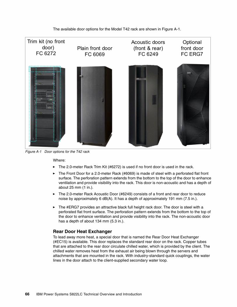
The available door options for the Model T42 rack are shown in Figure A-1.
Figure A-1 Door options for the T42 rack
Where:
� The 2.0-meter Rack Trim Kit (#6272) is used if no front door is used in the rack.
� The Front Door for a 2.0-meter Rack (#6069) is made of steel with a perforated flat front surface. The perforation pattern extends from the bottom to the top of the door to enhance ventilation and provide visibility into the rack. This door is non-acoustic and has a depth of about 25 mm (1 in.).
� The 2.0-meter Rack Acoustic Door (#6249) consists of a front and rear door to reduce noise by approximately 6 dB(A). It has a depth of approximately 191 mm (7.5 in.).
� The #ERG7 provides an attractive black full height rack door. The door is steel with a perforated flat front surface. The perforation pattern extends from the bottom to the top of the door to enhance ventilation and provide visibility into the rack. The non-acoustic door has a depth of about 134 mm (5.3 in.).
Rear Door Heat ExchangerTo lead away more heat, a special door that is named the Rear Door Heat Exchanger (#EC15) is available. This door replaces the standard rear door on the rack. Copper tubes that are attached to the rear door circulate chilled water, which is provided by the client. The chilled water removes heat from the exhaust air being blown through the servers and attachments that are mounted in the rack. With industry-standard quick couplings, the water lines in the door attach to the client-supplied secondary water loop.
Trim kit (no front door)
FC 6272Plain front door
FC 6069
Acoustic doors (front & rear)
FC 6249
Optionalfront doorFC ERG7
66 IBM Power Systems S822LC Technical Overview and Introduction
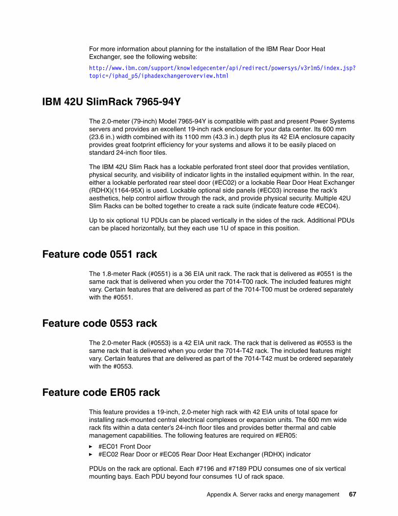
For more information about planning for the installation of the IBM Rear Door Heat Exchanger, see the following website:
http://www.ibm.com/support/knowledgecenter/api/redirect/powersys/v3r1m5/index.jsp?topic=/iphad_p5/iphadexchangeroverview.html
IBM 42U SlimRack 7965-94Y
The 2.0-meter (79-inch) Model 7965-94Y is compatible with past and present Power Systems servers and provides an excellent 19-inch rack enclosure for your data center. Its 600 mm (23.6 in.) width combined with its 1100 mm (43.3 in.) depth plus its 42 EIA enclosure capacity provides great footprint efficiency for your systems and allows it to be easily placed on standard 24-inch floor tiles.
The IBM 42U Slim Rack has a lockable perforated front steel door that provides ventilation, physical security, and visibility of indicator lights in the installed equipment within. In the rear, either a lockable perforated rear steel door (#EC02) or a lockable Rear Door Heat Exchanger (RDHX)(1164-95X) is used. Lockable optional side panels (#EC03) increase the rack’s aesthetics, help control airflow through the rack, and provide physical security. Multiple 42U Slim Racks can be bolted together to create a rack suite (indicate feature code #EC04).
Up to six optional 1U PDUs can be placed vertically in the sides of the rack. Additional PDUs can be placed horizontally, but they each use 1U of space in this position.
Feature code 0551 rack
The 1.8-meter Rack (#0551) is a 36 EIA unit rack. The rack that is delivered as #0551 is the same rack that is delivered when you order the 7014-T00 rack. The included features might vary. Certain features that are delivered as part of the 7014-T00 must be ordered separately with the #0551.
Feature code 0553 rack
The 2.0-meter Rack (#0553) is a 42 EIA unit rack. The rack that is delivered as #0553 is the same rack that is delivered when you order the 7014-T42 rack. The included features might vary. Certain features that are delivered as part of the 7014-T42 must be ordered separately with the #0553.
Feature code ER05 rack
This feature provides a 19-inch, 2.0-meter high rack with 42 EIA units of total space for installing rack-mounted central electrical complexes or expansion units. The 600 mm wide rack fits within a data center’s 24-inch floor tiles and provides better thermal and cable management capabilities. The following features are required on #ER05:
� #EC01 Front Door� #EC02 Rear Door or #EC05 Rear Door Heat Exchanger (RDHX) indicator
PDUs on the rack are optional. Each #7196 and #7189 PDU consumes one of six vertical mounting bays. Each PDU beyond four consumes 1U of rack space.
Appendix A. Server racks and energy management 67
If you order Power Systems equipment in an MES order, use the equivalent rack feature ER05 instead of 7965-94Y so that IBM Manufacturing can ship the hardware in the rack.
The AC power distribution unit and rack content
For rack models T00 and T42, 12-outlet PDUs are available. These PDUs include the AC power distribution unit #7188 and the AC Intelligent PDU+ #7109. The Intelligent PDU+ is identical to #7188 PDUs, but it is equipped with one Ethernet port, one console serial port, and one RS232 serial port for power monitoring.
The PDUs have 12 client-usable IEC 320-C13 outlets. Six groups of two outlets are fed by six circuit breakers. Each outlet is rated up to 10 amps, but each group of two outlets is fed from one 15 amp circuit breaker.
68 IBM Power Systems S822LC Technical Overview and Introduction
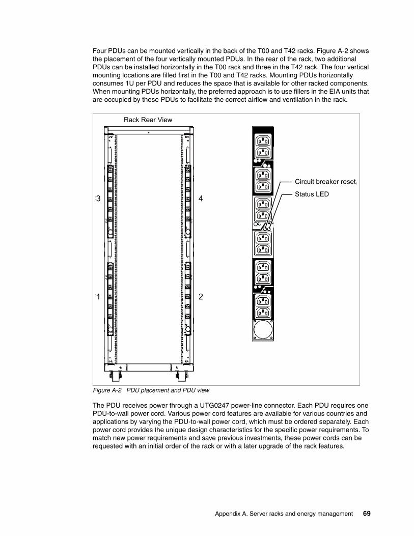
Four PDUs can be mounted vertically in the back of the T00 and T42 racks. Figure A-2 shows the placement of the four vertically mounted PDUs. In the rear of the rack, two additional PDUs can be installed horizontally in the T00 rack and three in the T42 rack. The four vertical mounting locations are filled first in the T00 and T42 racks. Mounting PDUs horizontally consumes 1U per PDU and reduces the space that is available for other racked components. When mounting PDUs horizontally, the preferred approach is to use fillers in the EIA units that are occupied by these PDUs to facilitate the correct airflow and ventilation in the rack.
Figure A-2 PDU placement and PDU view
The PDU receives power through a UTG0247 power-line connector. Each PDU requires one PDU-to-wall power cord. Various power cord features are available for various countries and applications by varying the PDU-to-wall power cord, which must be ordered separately. Each power cord provides the unique design characteristics for the specific power requirements. To match new power requirements and save previous investments, these power cords can be requested with an initial order of the rack or with a later upgrade of the rack features.
Rack Rear View
43
21
Circuit breaker reset
Status LED
Appendix A. Server racks and energy management 69
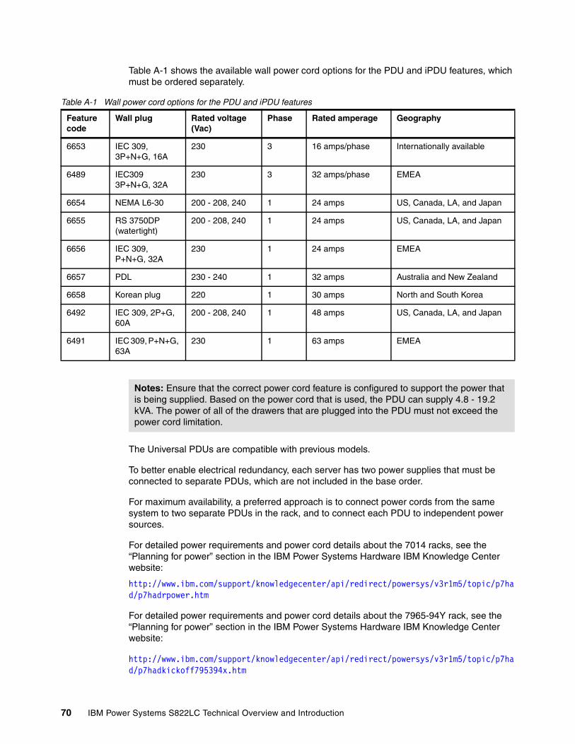
Table A-1 shows the available wall power cord options for the PDU and iPDU features, which must be ordered separately.
Table A-1 Wall power cord options for the PDU and iPDU features
The Universal PDUs are compatible with previous models.
To better enable electrical redundancy, each server has two power supplies that must be connected to separate PDUs, which are not included in the base order.
For maximum availability, a preferred approach is to connect power cords from the same system to two separate PDUs in the rack, and to connect each PDU to independent power sources.
For detailed power requirements and power cord details about the 7014 racks, see the “Planning for power” section in the IBM Power Systems Hardware IBM Knowledge Center website:
http://www.ibm.com/support/knowledgecenter/api/redirect/powersys/v3r1m5/topic/p7had/p7hadrpower.htm
For detailed power requirements and power cord details about the 7965-94Y rack, see the “Planning for power” section in the IBM Power Systems Hardware IBM Knowledge Center website:
http://www.ibm.com/support/knowledgecenter/api/redirect/powersys/v3r1m5/topic/p7had/p7hadkickoff795394x.htm
Feature code
Wall plug Rated voltage (Vac)
Phase Rated amperage Geography
6653 IEC 309, 3P+N+G, 16A
230 3 16 amps/phase Internationally available
6489 IEC309 3P+N+G, 32A
230 3 32 amps/phase EMEA
6654 NEMA L6-30 200 - 208, 240 1 24 amps US, Canada, LA, and Japan
6655 RS 3750DP (watertight)
200 - 208, 240 1 24 amps US, Canada, LA, and Japan
6656 IEC 309,P+N+G, 32A
230 1 24 amps EMEA
6657 PDL 230 - 240 1 32 amps Australia and New Zealand
6658 Korean plug 220 1 30 amps North and South Korea
6492 IEC 309, 2P+G, 60A
200 - 208, 240 1 48 amps US, Canada, LA, and Japan
6491 IEC 309, P+N+G, 63A
230 1 63 amps EMEA
Notes: Ensure that the correct power cord feature is configured to support the power that is being supplied. Based on the power cord that is used, the PDU can supply 4.8 - 19.2 kVA. The power of all of the drawers that are plugged into the PDU must not exceed the power cord limitation.
70 IBM Power Systems S822LC Technical Overview and Introduction
Rack-mounting rules
Consider the following primary rules when you mount the system into a rack:
� The system can be placed at any location in the rack. For rack stability, start filling a rack from the bottom.
� Any remaining space in the rack can be used to install other systems or peripheral devices if the maximum permissible weight of the rack is not exceeded and the installation rules for these devices are followed.
� Before placing the system into the service position, be sure to follow the rack manufacturer’s safety instructions regarding rack stability.
Useful rack additions
This section highlights several rack addition solutions for Power Systems rack-based systems.
OEM racks
The system can be installed in a suitable OEM rack if that the rack conforms to the EIA-310-D standard for 19-inch racks. This standard is published by the Electrical Industries Alliance. For more information, see the IBM Power Systems Hardware IBM Knowledge Center at the following website:
http://www.ibm.com/support/knowledgecenter/api/redirect/systems/scope/hw/index.jsp
Appendix A. Server racks and energy management 71
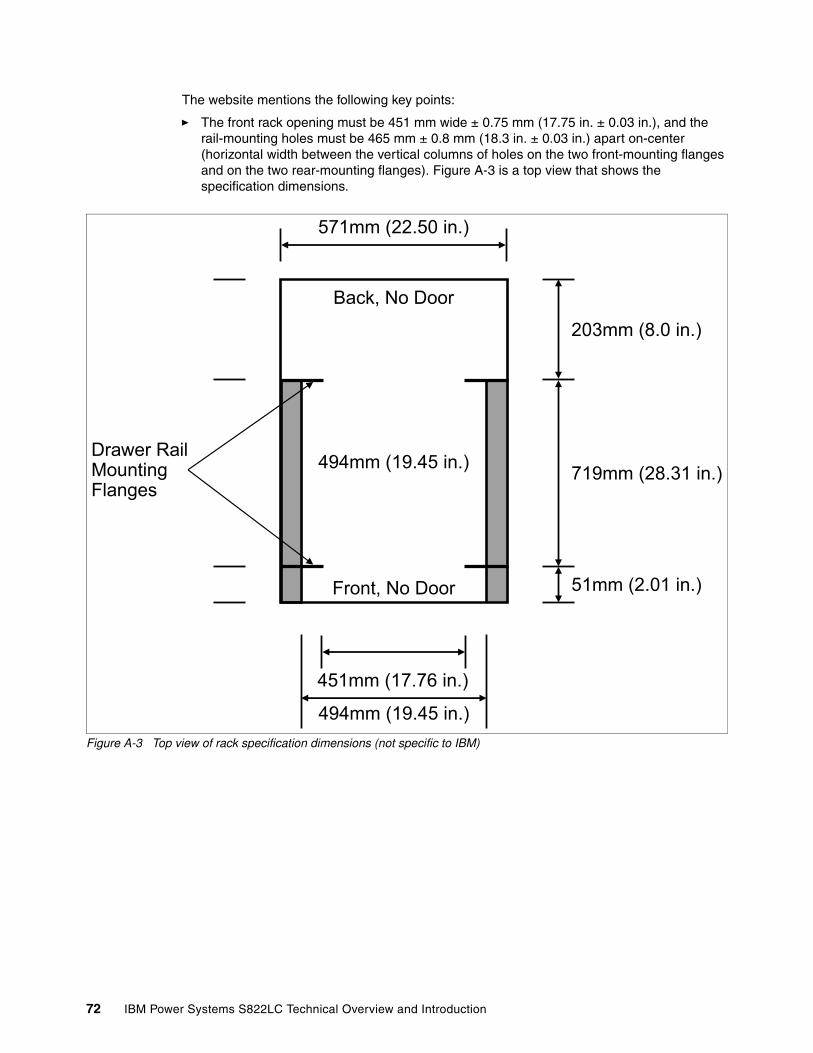
The website mentions the following key points:
� The front rack opening must be 451 mm wide ± 0.75 mm (17.75 in. ± 0.03 in.), and the rail-mounting holes must be 465 mm ± 0.8 mm (18.3 in. ± 0.03 in.) apart on-center (horizontal width between the vertical columns of holes on the two front-mounting flanges and on the two rear-mounting flanges). Figure A-3 is a top view that shows the specification dimensions.
Figure A-3 Top view of rack specification dimensions (not specific to IBM)
571mm (22.50 in.)
Drawer RailMountingFlanges
Back, No Door
494mm (19.45 in.)
Front, No Door
203mm (8.0 in.)
719mm (28.31 in.)
51mm (2.01 in.)
451mm (17.76 in.)
494mm (19.45 in.)
72 IBM Power Systems S822LC Technical Overview and Introduction
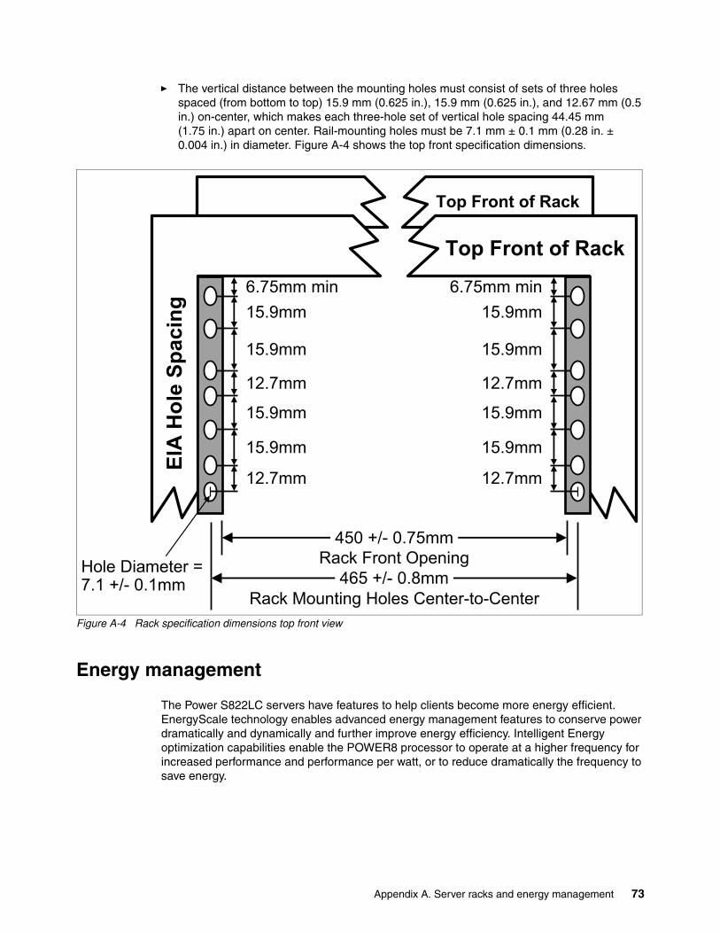
� The vertical distance between the mounting holes must consist of sets of three holes spaced (from bottom to top) 15.9 mm (0.625 in.), 15.9 mm (0.625 in.), and 12.67 mm (0.5 in.) on-center, which makes each three-hole set of vertical hole spacing 44.45 mm (1.75 in.) apart on center. Rail-mounting holes must be 7.1 mm ± 0.1 mm (0.28 in. ± 0.004 in.) in diameter. Figure A-4 shows the top front specification dimensions.
Figure A-4 Rack specification dimensions top front view
Energy management
The Power S822LC servers have features to help clients become more energy efficient. EnergyScale technology enables advanced energy management features to conserve power dramatically and dynamically and further improve energy efficiency. Intelligent Energy optimization capabilities enable the POWER8 processor to operate at a higher frequency for increased performance and performance per watt, or to reduce dramatically the frequency to save energy.
Hole Diameter =7.1 +/- 0.1mm
Rack Mounting Holes Center-to-Center
Rack Front Opening 450 +/- 0.75mm
465 +/- 0.8mm
EIA
Hol
e Sp
acin
g
6.75mm min15.9mm
15.9mm
12.7mm
15.9mm
15.9mm
12.7mm
6.75mm min15.9mm
15.9mm
12.7mm
15.9mm
15.9mm
12.7mm
Top Front of Rack
Top Front of Rack
Appendix A. Server racks and energy management 73
IBM EnergyScale technology
IBM EnergyScale technology provides functions to help the user understand and dynamically optimize processor performance versus processor energy consumption, and system workload, to control Power Systems power and cooling usage.
EnergyScale uses power and thermal information that is collected from the system to implement policies that can lead to better performance or better energy usage. EnergyScale offers the following features:
� Power trending
EnergyScale provides continuous collection of real-time server energy consumption. Administrators can use it to predict power consumption across their infrastructure and to react to business and processing needs. For example, administrators can use this information to predict data center energy consumption at various times of the day, week, or month.
� Power saver mode
Power saver mode lowers the processor frequency and voltage a fixed amount, reducing the energy consumption of the system while still delivering predictable performance. This percentage is predetermined to be within a safe operating limit and is not user-configurable. The server is designed for a fixed frequency drop of almost 50% down from nominal frequency (the actual value depends on the server type and configuration).
Power saver mode is not supported during system start, although it is a persistent condition that is sustained after the start when the system starts running instructions.
� Dynamic power saver mode
Dynamic power saver mode varies processor frequency and voltage based on the usage of the POWER8 processors. Processor frequency and usage are inversely proportional for most workloads, implying that as the frequency of a processor increases, its usage decreases, given a constant workload. Dynamic power saver mode takes advantage of this relationship to detect opportunities to save power, based on measured real-time system usage.
When a system is idle, the system firmware lowers the frequency and voltage to power energy saver mode values. When fully used, the maximum frequency varies, depending on whether the user favors power savings or system performance. If an administrator prefers energy savings and a system is fully used, the system reduced the maximum frequency to about 95% of nominal values. If performance is favored over energy consumption, the maximum frequency can be increased to up to 111.3% of nominal frequency for extra performance.
Dynamic power saver mode is mutually exclusive with power saver mode. Only one of these modes can be enabled at a time.
� Power capping
Power capping enforces a user-specified limit on power usage. Power capping is not a power-saving mechanism. It enforces power caps by throttling the processors in the system, degrading performance significantly. The idea of a power cap is to set a limit that must never be reached but that frees extra power that was never used in the data center. The margined power is this amount of extra power that is allocated to a server during its installation in a data center. It is based on the server environmental specifications that usually are never reached because server specifications are always based on maximum configurations and worst-case scenarios.
74 IBM Power Systems S822LC Technical Overview and Introduction
� Soft power capping
There are two power ranges into which the power cap can be set: power capping, as described previously, and soft power capping. Soft power capping extends the allowed energy capping range further, beyond a region that can be ensured in all configurations and conditions. If the energy management goal is to meet a particular consumption limit, soft power capping is the mechanism to use.
� Processor core nap mode
The POWER8 processor uses a low-power mode that is called nap that stops processor execution when there is no work to do on that processor core. The latency of exiting nap mode is small, typically not generating any impact on applications that are running.
Therefore, the IBM POWER Hypervisor™ can use nap mode as a general-purpose idle state. When the operating system detects that a processor thread is idle, it yields control of a hardware thread to the POWER Hypervisor. The POWER Hypervisor immediately puts the thread into nap mode. Nap mode allows the hardware to turn off the clock on most of the circuits in the processor core. Reducing active energy consumption by turning off the clocks allows the temperature to fall, which further reduces leakage (static) power of the circuits and causes a cumulative effect. Nap mode saves 10 - 15% of power consumption in the processor core.
� Processor core sleep mode
To save even more energy, the POWER8 processor has an even lower power mode referred to as sleep. Before a core and its associated private L2 cache enter sleep mode, the cache is flushed, transition lookaside buffers (TLB) are invalidated, and the hardware clock is turned off in the core and in the cache. Voltage is reduced to minimize leakage current. Processor cores that are inactive in the system (such as capacity on demand (CoD) processor cores) are kept in sleep mode. Sleep mode saves about 80% of the power consumption in the processor core and its associated private L2 cache.
� Processor chip winkle mode
The most energy can be saved when a whole POWER8 chiplet enters the winkle mode. In this mode, the entire chiplet is turned off, including the L3 cache. This mode can save more than 95% power consumption.
� Fan control and altitude input
System firmware dynamically adjusts fan speed based on energy consumption, altitude, ambient temperature, and energy savings modes. Power Systems are designed to operate in worst-case environments, in hot ambient temperatures, at high altitudes, and with high-power components. In a typical case, one or more of these constraints are not valid. When no power savings setting is enabled, fan speed is based on ambient temperature and assumes a high-altitude environment. When a power savings setting is enforced (either Power Energy Saver Mode or Dynamic Power Saver Mode), the fan speed varies based on power consumption and ambient temperature.
� Processor folding
Processor folding is a consolidation technique that dynamically adjusts, over the short term, the number of processors that are available for dispatch to match the number of processors that are demanded by the workload. As the workload increases, the number of processors made available increases. As the workload decreases, the number of processors that are made available decreases. Processor folding increases energy savings during periods of low to moderate workload because unavailable processors remain in low-power idle states (nap or sleep) longer.
Appendix A. Server racks and energy management 75
� EnergyScale for I/O
POWER8 processor-based systems automatically power off hot-pluggable PCI adapter slots that are empty or not being used. System firmware automatically scans all pluggable PCI slots at regular intervals, looking for those slots that meet the criteria for being not in use and powering them off. This support is available for all POWER8 processor-based servers and the expansion units that they support.
� Dynamic power saver mode
On POWER8 processor-based systems, several EnergyScale technologies are embedded in the hardware and do not require an operating system or external management component. Fan control, environmental monitoring, and system energy management are controlled by the On Chip Controller (OCC) and associated components.
On Chip Controller
POWER8 invested in power management innovations. A new OCC that uses an embedded IBM PowerPC® core with 512 KB of SRAM runs real-time control firmware to respond to workload variations by adjusting the per-core frequency and voltage based on activity, thermal, voltage, and current sensors.
The OCC also enables more granularity in controlling the energy parameters in the processor, and increases reliability in energy management by having one controller in each processor that can perform certain functions independently of the others.
POWER8 also includes an internal voltage regulation capability that enables each core to run at a different voltage. Optimizing both voltage and frequency for workload variation enables a better increase in power savings versus optimizing frequency only.
Energy consumption estimation
Often, for Power Systems servers, various energy-related values are important:
� Maximum power consumption and power source loading values
These values are important for site planning and are described in the POWER8 processor-based systems information IBM Knowledge Center at the following website:
http://www.ibm.com/support/knowledgecenter/api/redirect/powersys/v3r1m5/index.jsp
Search for type and model number and “server specifications”. For example, for the Power S822LC servers, search for “8335-GCA” or “8335-GTA”.
� An estimation of the energy consumption for a certain configuration
Calculate the energy consumption for a certain configuration in the IBM Systems Energy Estimator at the following website:
http://www-912.ibm.com/see/EnergyEstimator
In that tool, select the type and model for the system, and enter details about the configuration and CPU usage that you want. As a result, the tool shows the estimated energy consumption and the waste heat at the usage that you want and also at full usage.
76 IBM Power Systems S822LC Technical Overview and Introduction
Related publications
The publications that are listed in this section are considered suitable for a more detailed description of the topics covered in this paper.
IBM Redbooks
The following IBM Redbooks publications provide additional information about the topic in this document. Some publications that are referenced in this list might be available in softcopy only.
� Cloud Security Guidelines for IBM Power Systems, SG24-8242
� IBM PowerKVM Configuration and Use, SG24-8231
� IBM Power System S824L Technical Overview and Introduction, REDP-5139
� IBM PowerVC Version 1.2.3: Introduction and Configuration, SG24-8199
� IBM z13 Configuration Setup, SG24-8260
� NVIDIA CUDA on IBM POWER8: Technical Overview, Software Installation, and Application, REDP-5169
� Performance Optimization and Tuning Techniques for IBM Power Systems Processors Including IBM POWER8, SG24-8171
You can search for, view, download, or order these documents and other Redbooks, Redpapers, web docs, draft and additional materials, at the following website:
ibm.com/redbooks
Other publications
These publications are also relevant as further information sources:
� Active Memory Expansion: Overview and Usage Guide
http://public.dhe.ibm.com/common/ssi/ecm/en/pow03037usen/POW03037USEN.PDF
� IBM EnergyScale for POWER8 Processor-Based Systems
http://public.dhe.ibm.com/common/ssi/ecm/en/pow03039usen/POW03039USEN.PDF
� IBM Power Facts and Features - IBM Power Systems, IBM PureFlex System, and Power Blades
http://www.ibm.com/systems/power/hardware/reports/factsfeatures.html
� IBM Power Systems S812L server specifications
http://www.ibm.com/systems/power/hardware/s812l-s822l/specs.html
� IBM Power Systems S814 server specifications
http://www.ibm.com/systems/power/hardware/s814/specs.html
� IBM Power Systems S822 server specifications
http://www.ibm.com/systems/power/hardware/s822/specs.html
© Copyright IBM Corp. 2015. All rights reserved. 77
� IBM Power Systems S822L server specifications
http://www.ibm.com/systems/power/hardware/s812l-s822l/specs.html
� IBM Power Systems S824 server specifications
http://www.ibm.com/systems/power/hardware/s824/specs.html
� IBM Power Systems S824L server specifications:
http://www.ibm.com/systems/power/hardware/s824l/specs.html
� IBM Power Systems E850 server specifications:
http://www.ibm.com/systems/power/hardware/e850/specs.html
� IBM Power Systems E870 server specifications:
http://www.ibm.com/systems/power/hardware/e870/specs.html
� IBM Power Systems E870 server specifications:
http://www.ibm.com/systems/power/hardware/e870/specs.html
� System RAS - Introduction to Power Systems Reliability, Availability, and Serviceability
http://public.dhe.ibm.com/common/ssi/ecm/en/pow03056usen/POW03056USEN.PDF
Online resources
These websites are also relevant as further information sources:
� IBM Fix Central website
http://www.ibm.com/support/fixcentral/
� IBM Knowledge Center
http://www.ibm.com/support/knowledgecenter/
� IBM Power Systems website
http://www.ibm.com/systems/power/
� IBM Power Systems Hardware IBM Knowledge Center:
http://www.ibm.com/support/knowledgecenter/api/redirect/powersys/v3r1m5/index.jsp
� IBM Storage website
http://www.ibm.com/systems/storage/
� IBM System Planning Tool website
http://www.ibm.com/systems/support/tools/systemplanningtool/
� IBM Systems Energy Estimator
http://www-912.ibm.com/see/EnergyEstimator/
� Current information about IBM Java and tested Linux distributions are available here:
https://www.ibm.com/developerworks/java/jdk/linux/tested.html
� Additional information about the OpenJDK port for Linux on PPC64 LE, as well as some pre-generated builds can be found here:
http://cr.openjdk.java.net/~simonis/ppc-aix-port/
� Launchpad.net has resources for Ubuntu builds. You can find out about them here:
https://launchpad.net/ubuntu/+source/openjdk-9https://launchpad.net/ubuntu/+source/openjdk-8
78 IBM Power Systems S822LC Technical Overview and Introduction
https://launchpad.net/ubuntu/+source/openjdk-7
Help from IBM
IBM Support and downloads
ibm.com/support
IBM Global Services
ibm.com/services
Related publications 79

80 IBM Power Systems S822LC Technical Overview and Introduction

ibm.com/redbooks
Printed in U.S.A.
Back cover
ISBN 073845480X
REDP-5283-00