Embed Size (px)
Citation preview
IBM i
NetworkingRemote Access Services7.1
IBM

IBM i
NetworkingRemote Access Services7.1
IBM

NoteBefore using this information and the product it supports, read the information in “Notices,” onpage 75.
This edition applies to IBM i 7.1 (product number 5770-SS1) and to all subsequent releases and modifications untilotherwise indicated in new editions. This version does not run on all reduced instruction set computer (RISC)models nor does it run on CISC models.
© Copyright IBM Corporation 1998, 2010.US Government Users Restricted Rights – Use, duplication or disclosure restricted by GSA ADP Schedule Contractwith IBM Corp.
Contents
Remote Access Services . . . . . . . 1What's new for IBM i 7.1 . . . . . . . . . . 1PDF file for Remote Access Services . . . . . . 2PPP concepts . . . . . . . . . . . . . . 2
What is PPP . . . . . . . . . . . . . 2Connection profiles . . . . . . . . . . . 3Group policy support . . . . . . . . . . 4
Scenarios: Remote access using PPP connections . . 5Example: PPP and DHCP on a single System i . . 5Example: DHCP and PPP profile on differentSystem i models . . . . . . . . . . . . 7Scenario: Protecting an L2TP voluntary tunnelwith IPSec . . . . . . . . . . . . . . 9Scenario: Protecting an L2TP voluntary tunnelwith IPSec . . . . . . . . . . . . . . 10
Configuring VPN on System A . . . . . . 12Configuring a PPP connection profile andvirtual line on System A . . . . . . . . 14Applying the l2tptocorp dynamic-key groupto the toCorp PPP profile . . . . . . . . 15Configuring VPN on System B . . . . . . 15Configuring a PPP connection profile andvirtual line on System B . . . . . . . . 15Activating packet rules . . . . . . . . 16
Scenario: Connecting your system to a PPPoEaccess concentrator . . . . . . . . . . . 16Scenario: Connecting remote dial-in clients toyour system . . . . . . . . . . . . . 19Scenario: Connecting your office LAN to theInternet with a modem . . . . . . . . . 21Scenario: Connecting your corporate and remotenetworks with a modem . . . . . . . . . 24Scenario: Authenticating dial-up connections withRADIUS NAS . . . . . . . . . . . . 28Scenario: Managing remote user access toresources using group policies and IP filtering. . 30Scenario: Sharing a modem between logicalpartitions using L2TP . . . . . . . . . . 33
Scenario details: Sharing a modem betweenlogical partitions using L2TP . . . . . . 34
Step 1: Configuring the L2TP terminatorprofile for any interface on the partitionthat owns the modems . . . . . . . 35Step 2: Configuring an L2TP originatorprofile on 10.1.1.74 . . . . . . . . . 36Step 3: Configuring an L2TP remote dialprofile for 192.168.1.2 . . . . . . . . 37Step 4: Testing the connection . . . . . 37
Planning PPP. . . . . . . . . . . . . . 38Software and hardware requirements . . . . . 38Connection alternatives . . . . . . . . . 39
Analog telephone lines . . . . . . . . 39Digital service and Digital Data Services. . . 40Switched-56 . . . . . . . . . . . . 40Integrated Services Digital Network . . . . 41T1/E1 and fractional T1 connections . . . . 42
Frame relay . . . . . . . . . . . . 42L2TP (tunneling) support for PPP connections 43
Voluntary tunnel . . . . . . . . . 44Compulsory tunnel model - incoming call 44Compulsory tunnel model - remote dial . . 44L2TP multi-hop connection . . . . . . 44
PPPoE (DSL) support for PPP connections . . 44Connection equipment. . . . . . . . . . 45
Modems . . . . . . . . . . . . . 45CSU/DSU . . . . . . . . . . . . . 45ISDN terminal adapters . . . . . . . . 46
ISDN terminal adapter suggestions . . . 46ISDN terminal adapter restrictions. . . . 47
IP address handling . . . . . . . . . . 47IP packet filtering . . . . . . . . . . 48IP address management strategy . . . . . 48
System authentication . . . . . . . . . . 52Challenge Handshake Authentication Protocolwith MD5 . . . . . . . . . . . . . 52Extensible Authentication Protocol. . . . . 52Password Authentication Protocol . . . . . 53Remote Authentication Dial In User Serviceoverview . . . . . . . . . . . . . 53Validation list. . . . . . . . . . . . 54
Bandwidth considerations for multilink . . . . 54Configuring PPP . . . . . . . . . . . . 54
Creating a connection profile . . . . . . . 55Protocol type: PPP or Serial Line InternetProtocol (SLIP) . . . . . . . . . . . 56Mode selections . . . . . . . . . . . 56
Switched line . . . . . . . . . . . 56Leased line . . . . . . . . . . . 57L2TP (virtual line) . . . . . . . . . 57PPPoE line . . . . . . . . . . . 58
Link configuration . . . . . . . . . . 58Single line . . . . . . . . . . . . 59Line pool . . . . . . . . . . . . 59Multiple-connection profile support . . . 61
Configuring your modem for PPP . . . . . . 62Configuring a new modem . . . . . . . 63Setting modem command strings . . . . . 63Example: Configuring an ISDN terminaladapter . . . . . . . . . . . . . . 64Associating a modem with a line description 65
Configuring a remote PC . . . . . . . . . 65Configuring Internet access through the AT&TGlobal Network . . . . . . . . . . . . 66Connection wizards . . . . . . . . . . 66Configuring a group access policy . . . . . . 67Applying IP packet filtering rules to a PPPconnection. . . . . . . . . . . . . . 68Enabling RADIUS and DHCP services forconnection profiles . . . . . . . . . . . 69
Managing PPP . . . . . . . . . . . . . 69Setting properties for PPP connection profiles . . 69Monitoring PPP activity . . . . . . . . . 69
© Copyright IBM Corp. 1998, 2010 iii

Troubleshooting PPP . . . . . . . . . . . 72Related information for Remote Access Services . . 73
Appendix. Notices . . . . . . . . . . 75Programming interface information . . . . . . 77
Trademarks . . . . . . . . . . . . . . 77Terms and conditions . . . . . . . . . . . 77
iv IBM i: Networking Remote Access Services
Remote Access Services
Point-to-Point Protocol (PPP) is an Internet standard for transmitting data over serial lines.
PPP is the most widely used connection protocol among Internet service providers (ISPs). PPP enablesindividual computers to access networks. The networks in turn provide access to the Internet. The Systemi® product includes TCP/IP PPP support as part of its wide-area network (WAN) connectivity.
You can exchange data between locations by using PPP to connect a remote computer to your System iplatform. Through PPP, remote systems that are connected to your system can access resources or othermachines that belong to the same network as your system. You can also configure your system to connectto the Internet by using PPP. The System i Navigator Dial-Up Connection wizard can guide you throughthe process of connecting your system to the Internet or to an internal network.
What's new for IBM i 7.1Read about new or significantly changed information for the Remote Access Services: PPP connectionstopic collection.
IPv6 address support added for PPP connections
Starting in IBM i 7.1, PPP can support both IPv4 and IPv6 addresses. A PPP connection profile can haveonly IPv4 enabled, only IPv6 enabled, or both IPv4 and IPv6 enabled. By default, both IPv4 and IPv6 areenabled for a PPP connection profile.v IPv6 can be enabled in connection profiles to allow remote workers to use IPv6 to access the company
network.v If your ISP supports IPv6 addressing, you can also enable IPv6 in the originator profilev IPv6 access for remote office PCs is configured by enabling IP forwarding in the TCP/IP IPv6 Settings
section of the connection profiles.v In addition to IPv4 address management, IPv6 address management should now be considered.
Troubleshooting PPP with a communications trace
The troubleshooting PPP section was updated to mention that communication traces can be dumped in aPacket Capture (PCAP) format to be used with network protocol analyzers. This can be useful whentrying to debug network traffic.
How to see what's new or changed
To help you see where technical changes have been made, the information center uses:v The
image to mark where new or changed information begins.
v The
image to mark where new or changed information ends.
In PDF files, you might see revision bars (|) in the left margin of new and changed information.
To find other information about what's new or changed this release, see the Memo to users.
© Copyright IBM Corp. 1998, 2010 1
PDF file for Remote Access ServicesYou can view and print a PDF file of this information.
To view or download the PDF version of this document, select Remote Access Services (about 525 KB).
Saving PDF files
To save a PDF on your workstation for viewing or printing:1. Right-click the PDF link in your browser.2. Click the option that saves the PDF locally.3. Navigate to the directory in which you want to save the PDF.4. Click Save.
Downloading Adobe Reader
You need Adobe Reader installed on your system to view or print these PDFs. You can download a free
copy from the Adobe Web site (www.adobe.com/products/acrobat/readstep.html) .Related reference:“Related information for Remote Access Services” on page 73IBM® Redbooks® publications and Web sites contain information that relates to the Remote AccessServices topic collection. You can view or print any of the PDF files.
PPP conceptsYou can use PPP to connect a System i platform to remote networks, client PCs, another System iplatform, or an Internet service provider (ISP). To fully use this protocol, you should understand both thecapabilities and the IBM i support for this protocol.Related reference:“Related information for Remote Access Services” on page 73IBM Redbooks publications and Web sites contain information that relates to the Remote Access Servicestopic collection. You can view or print any of the PDF files.
What is PPPPoint-to-Point Protocol (PPP) is a TCP/IP protocol that is used to connect one computer system toanother. Computers use PPP to communicate over the telephone network or the Internet.
A PPP connection exists when two systems physically connect through a telephone line. You can use PPPto connect one system to another. For example, an established PPP connection between a branch officeand a central office allows either office to transfer data to the other through the network.
PPP allows interoperability among the remote access software of different manufacturers. It also allowsmultiple network communication protocols to use the same physical communication line.
The following Request for Comment (RFC) standards describe the PPP protocol. You can find more
information about the RFCs on the RFC Editor Web page .v RFC-1661 Point-to-Point Protocolv RFC-1662 PPP on HDLC-like framingv RFC-1994 PPP CHAPv RFC-5072 IP Version 6 over PPP
2 IBM i: Networking Remote Access Services
|
Connection profilesPoint-to-Point connection profiles define a set of parameters and resources for specific Point-to-PointProtocol (PPP) connections. You can start profiles that use these parameter settings to dial-out (originate)or to listen for (receive) PPP connections.
You can use the following two types of profiles to define a set of characteristics for a PPP connection orset of connections:v Originator connection profiles are point-to-point connections that originate from the local system and are
received by a remote system. You can configure outbound connections using this object.v Receiver connection profiles are point-to-point connections that originate from a remote system and are
received by the local system. You can configure inbound connections using this object.
A connection profile specifies how a PPP connection works. The information in a connection profileanswers these questions:v What type of connection protocol do you use? (PPP or Serial Line Internet Protocol (SLIP))v Does your system contact the other computer by dialing out (originator)? Does your system wait to
receive a call from the other system (receiver)?v What communications line does the connection use?v How should your system determine which IP address to use?v How should your system authenticate another system? Where should your system store the
authentication information?
The connection profile is the logical representation of the following connection details:v Line and profile typev Multilink settingsv Remote telephone numbers and dialing optionsv Authenticationv TCP/IP settings: IP addresses and routing, and IP filteringv Work management and connection customizationv Domain name servers
The system stores this configuration information in a connection profile. This information provides thenecessary context for your system to establish a PPP connection with another system. A connectionprofile contains the following information:v The protocol type. You can choose between PPP and SLIP. IBM suggests that you use PPP whenever
possible.v The mode selection. The mode selection specifies the connection type and the operating mode for this
connection profile.Connection type. This specifies the type of line your connections rest on and whether they are dial(originator) or answer (receiver). You can select among these connection types:– Switched line– Leased (dedicated) line– Layer Two Tunneling Protocol (L2TP) (virtual line)– Point-to-Point Protocol over Ethernet (PPPoE) (virtual line)PPPoE is only supported for originator connection profiles.
v Operation mode. The available operating mode depends on the type of connection.
Remote Access Services 3
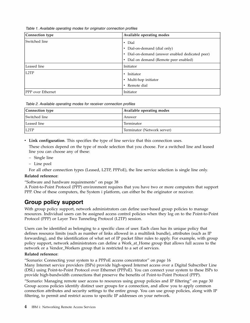
Table 1. Available operating modes for originator connection profiles
Connection type Available operating modes
Switched line v Dial
v Dial-on-demand (dial only)
v Dial-on-demand (answer enabled dedicated peer)
v Dial on demand (Remote peer enabled)
Leased line Initiator
L2TP v Initiator
v Multi-hop initiator
v Remote dial
PPP over Ethernet Initiator
Table 2. Available operating modes for receiver connection profiles
Connection type Available operating modes
Switched line Answer
Leased line Terminator
L2TP Terminator (Network server)
v Link configuration. This specifies the type of line service that this connection uses.These choices depend on the type of mode selection that you choose. For a switched line and leasedline you can choose any of these:– Single line– Line poolFor all other connection types (Leased, L2TP, PPPoE), the line service selection is single line only.
Related reference:“Software and hardware requirements” on page 38A Point-to-Point Protocol (PPP) environment requires that you have two or more computers that supportPPP. One of these computers, the System i platform, can either be the originator or receiver.
Group policy supportWith group policy support, network administrators can define user-based group policies to manageresources. Individual users can be assigned access control policies when they log on to the Point-to-PointProtocol (PPP) or Layer Two Tunneling Protocol (L2TP) session.
Users can be identified as belonging to a specific class of user. Each class has its unique policy thatdefines resource limits (such as number of links allowed in a multilink bundle), attributes (such as IPforwarding), and the identification of what set of IP packet filter rules to apply. For example, with grouppolicy support, network administrators can define a Work_at_Home group that allows full access to thenetwork or a Vendor_Workers group that is restricted to a set of services.Related reference:“Scenario: Connecting your system to a PPPoE access concentrator” on page 16Many Internet service providers (ISPs) provide high-speed Internet access over a Digital Subscriber Line(DSL) using Point-to-Point Protocol over Ethernet (PPPoE). You can connect your system to these ISPs toprovide high-bandwidth connections that preserve the benefits of Point-to-Point Protocol (PPP).“Scenario: Managing remote user access to resources using group policies and IP filtering” on page 30Group access policies identify distinct user groups for a connection, and allow you to apply commonconnection attributes and security settings to the entire group. You can use group policies, along with IPfiltering, to permit and restrict access to specific IP addresses on your network.
4 IBM i: Networking Remote Access Services
Scenarios: Remote access using PPP connectionsThese scenarios describe how Point-to-Point Protocol (PPP) works and how to implement a PPPenvironment in a network. The scenarios also introduce fundamental PPP concepts from which beginnersand experienced users can benefit before you proceed to the planning and configuration tasks.Related reference:“Related information for Remote Access Services” on page 73IBM Redbooks publications and Web sites contain information that relates to the Remote Access Servicestopic collection. You can view or print any of the PDF files.
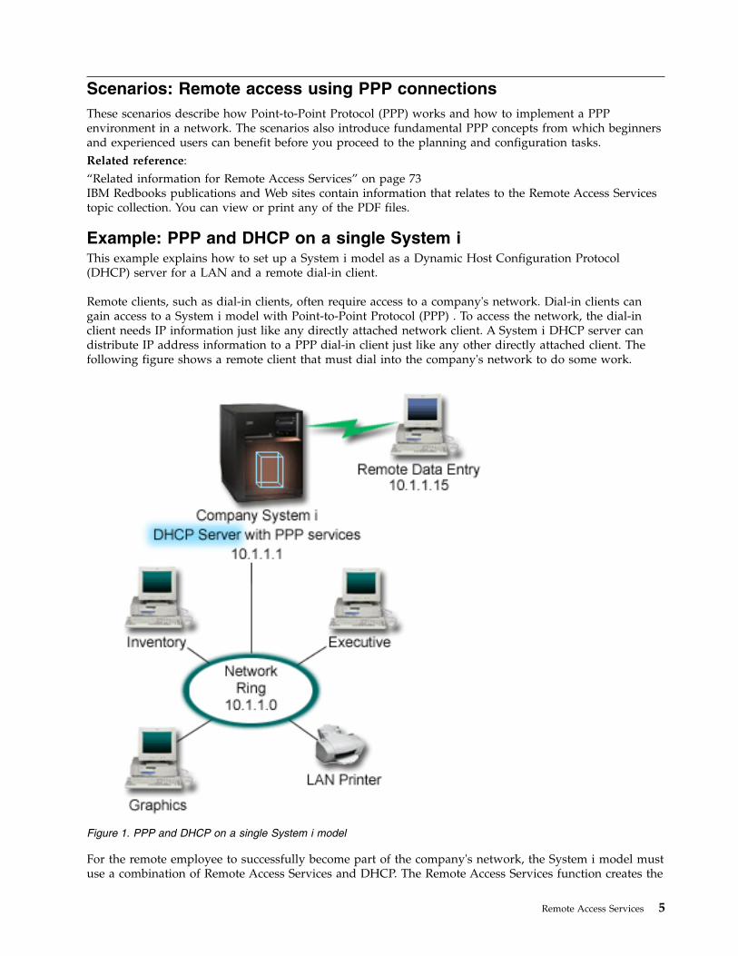
Example: PPP and DHCP on a single System iThis example explains how to set up a System i model as a Dynamic Host Configuration Protocol(DHCP) server for a LAN and a remote dial-in client.
Remote clients, such as dial-in clients, often require access to a company's network. Dial-in clients cangain access to a System i model with Point-to-Point Protocol (PPP) . To access the network, the dial-inclient needs IP information just like any directly attached network client. A System i DHCP server candistribute IP address information to a PPP dial-in client just like any other directly attached client. Thefollowing figure shows a remote client that must dial into the company's network to do some work.
For the remote employee to successfully become part of the company's network, the System i model mustuse a combination of Remote Access Services and DHCP. The Remote Access Services function creates the
Figure 1. PPP and DHCP on a single System i model
Remote Access Services 5
dial-in capability for the System i model. If set up properly, after the client establishes the dial-inconnection, the PPP server tells the DHCP server to distribute TCP/IP information to the remote client.
In this example, a single DHCP subnet policy covers both the on-site network clients and the dial-inclients.
If you want your PPP profile to defer to the DHCP for IP distribution, you must do so in the PPP profile.In the TCP/IP settings of the receiver connection profile, set the remote IP address assignment methodfrom Fixed to DHCP. To allow the dial-in clients to communicate with other network clients, like theLAN printer, you must also allow IP forwarding in the TCP/IP settings of the profile and the TCP/IPconfiguration (stack) properties. If you only set IP forwarding on in the PPP profile, the System i modelwill not pass the IP packets. You must set IP forwarding on in both the profile and the stack.
Also, the local interface IP address in the PPP profile must be an IP address that falls within the subnetdefinition in the DHCP server. In this example, the PPP profile local interface IP address must be 10.1.1.1.This address must also be excluded from the DHCP server's address pool so that it is not assigned to aDHCP client.
Planning the DHCP setup for on-site and PPP clients
Table 3. Global configuration options (applies to all clients served by the DHCP server)
Object Value
Configurationoptions
Option 1: Subnet mask 255.255.255.0
Option 6: Domain name server 10.1.1.1
Option 15: Domain name mycompany.com
Is the system performing DNS updates? No
Is the system supporting BOOTP clients? No
Table 4. Subnet for both on-site and dial-in clients
Object Value
Subnet Name MainNetwork
Addresses to manage 10.1.1.3 - 10.1.1.150
Lease time 24 hours (default)
Configurationoptions
Inherited options Options from Global configuration
Subnet addresses not assigned by server 10.1.1.1 (Local interface address specified in theTCP/IP Settings of the Receiver ConnectionProfile properties in System i Navigator)
Other setupv Set the Remote IP address method to DHCP in the PPP receiver connection profile.
1. Enable DHCP WAN client connection with a DHCP server or relay connection using the Servicesmenu item for Remote Access Services in System i Navigator.
2. Select to use DHCP for the IP address assignment method under the TCP/IP Settings Properties ofthe Receiver Connection Profile in System i Navigator.
v Allow remote system to access other networks (IP forwarding) under the TCP/IP Settings Properties ofthe Receiver Connection Profile in System i Navigator.
v Enable IP datagram forwarding under the Settings Properties of the TCP/IP Configuration in System iNavigator.
6 IBM i: Networking Remote Access Services
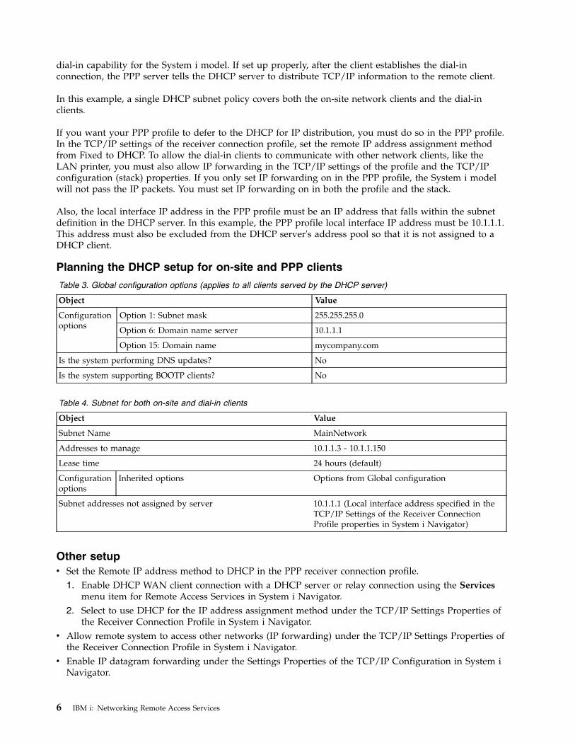
Example: DHCP and PPP profile on different System i modelsThis example explains how to set up two System i models as the network Dynamic Host ConfigurationProtocol (DHCP) server and the BOOTP/DHCP relay agent for two LANs and remote dial-in clients.
The example about PPP and DHCP on a single System i model shows how to use PPP and DHCP on asingle system to permit dial-in clients access to a network. If you are concerned with the physical layoutof your network or with security, it might be better to have the PPP and DHCP servers separated or tohave a dedicated PPP server without DHCP services. The following figure represents a network that hasdial-in clients with the PPP and DHCP policies on different servers.
The remote data entry clients dial into the System i PPP server. The PPP profile on that server must havea remote IP address method of DHCP, such as the one used in the example of PPP and DHCP on a single
Figure 2. DHCP and PPP profile on different System i models
Remote Access Services 7
System i model. The PPP profile and the TCP/IP stack properties on the PPP server must have IPforwarding. Furthermore, because this server is acting as a DHCP relay agent, the BOOTP/DHCP relayagent must be on. This allows the System i Remote Access server to pass on DHCPDISCOVER packets tothe DHCP server. The DHCP server then responds and distributes TCP/IP information to the dial-inclients through the PPP server.
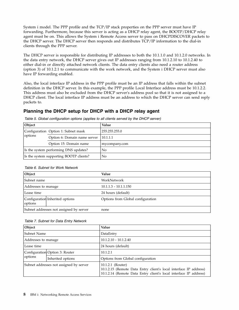
The DHCP server is responsible for distributing IP addresses to both the 10.1.1.0 and 10.1.2.0 networks. Inthe data entry network, the DHCP server gives out IP addresses ranging from 10.1.2.10 to 10.1.2.40 toeither dial-in or directly attached network clients. The data entry clients also need a router address(option 3) of 10.1.2.1 to communicate with the work network, and the System i DHCP server must alsohave IP forwarding enabled.
Also, the local interface IP address in the PPP profile must be an IP address that falls within the subnetdefinition in the DHCP server. In this example, the PPP profile Local Interface address must be 10.1.2.2.This address must also be excluded from the DHCP server's address pool so that it is not assigned to aDHCP client. The local interface IP address must be an address to which the DHCP server can send replypackets to.
Planning the DHCP setup for DHCP with a DHCP relay agent
Table 5. Global configuration options (applies to all clients served by the DHCP server)
Object Value
Configurationoptions
Option 1: Subnet mask 255.255.255.0
Option 6: Domain name server 10.1.1.1
Option 15: Domain name mycompany.com
Is the system performing DNS updates? No
Is the system supporting BOOTP clients? No
Table 6. Subnet for Work Network
Object Value
Subnet name WorkNetwork
Addresses to manage 10.1.1.3 - 10.1.1.150
Lease time 24 hours (default)
Configurationoptions
Inherited options Options from Global configuration
Subnet addresses not assigned by server none
Table 7. Subnet for Data Entry Network
Object Value
Subnet Name DataEntry
Addresses to manage 10.1.2.10 - 10.1.2.40
Lease time 24 hours (default)
Configurationoptions
Option 3: Router 10.1.2.1
Inherited options Options from Global configuration
Subnet addresses not assigned by server 10.1.2.1 (Router)10.1.2.15 (Remote Data Entry client's local interface IP address)10.1.2.14 (Remote Data Entry client's local interface IP address)
8 IBM i: Networking Remote Access Services
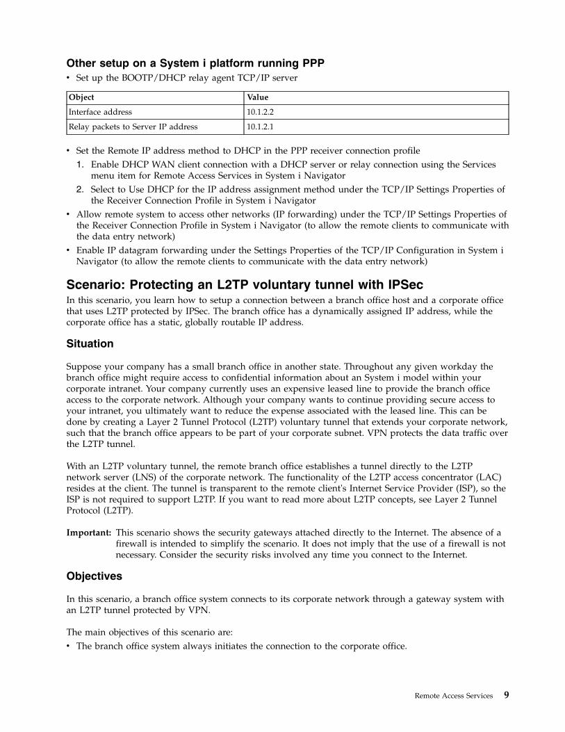
Other setup on a System i platform running PPPv Set up the BOOTP/DHCP relay agent TCP/IP server
Object Value
Interface address 10.1.2.2
Relay packets to Server IP address 10.1.2.1
v Set the Remote IP address method to DHCP in the PPP receiver connection profile1. Enable DHCP WAN client connection with a DHCP server or relay connection using the Services
menu item for Remote Access Services in System i Navigator2. Select to Use DHCP for the IP address assignment method under the TCP/IP Settings Properties of
the Receiver Connection Profile in System i Navigatorv Allow remote system to access other networks (IP forwarding) under the TCP/IP Settings Properties of
the Receiver Connection Profile in System i Navigator (to allow the remote clients to communicate withthe data entry network)
v Enable IP datagram forwarding under the Settings Properties of the TCP/IP Configuration in System iNavigator (to allow the remote clients to communicate with the data entry network)
Scenario: Protecting an L2TP voluntary tunnel with IPSecIn this scenario, you learn how to setup a connection between a branch office host and a corporate officethat uses L2TP protected by IPSec. The branch office has a dynamically assigned IP address, while thecorporate office has a static, globally routable IP address.
Situation
Suppose your company has a small branch office in another state. Throughout any given workday thebranch office might require access to confidential information about an System i model within yourcorporate intranet. Your company currently uses an expensive leased line to provide the branch officeaccess to the corporate network. Although your company wants to continue providing secure access toyour intranet, you ultimately want to reduce the expense associated with the leased line. This can bedone by creating a Layer 2 Tunnel Protocol (L2TP) voluntary tunnel that extends your corporate network,such that the branch office appears to be part of your corporate subnet. VPN protects the data traffic overthe L2TP tunnel.
With an L2TP voluntary tunnel, the remote branch office establishes a tunnel directly to the L2TPnetwork server (LNS) of the corporate network. The functionality of the L2TP access concentrator (LAC)resides at the client. The tunnel is transparent to the remote client's Internet Service Provider (ISP), so theISP is not required to support L2TP. If you want to read more about L2TP concepts, see Layer 2 TunnelProtocol (L2TP).
Important: This scenario shows the security gateways attached directly to the Internet. The absence of afirewall is intended to simplify the scenario. It does not imply that the use of a firewall is notnecessary. Consider the security risks involved any time you connect to the Internet.
Objectives
In this scenario, a branch office system connects to its corporate network through a gateway system withan L2TP tunnel protected by VPN.
The main objectives of this scenario are:v The branch office system always initiates the connection to the corporate office.
Remote Access Services 9
v The branch office system is the only system at the branch office network that needs access to thecorporate network. In other words, its role is that of a host, not a gateway, in the branch officenetwork.
v The corporate system a host computer in the corporate office network.
Details
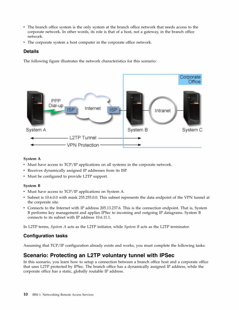
The following figure illustrates the network characteristics for this scenario:
System A
v Must have access to TCP/IP applications on all systems in the corporate network.v Receives dynamically assigned IP addresses from its ISP.v Must be configured to provide L2TP support.
System B
v Must have access to TCP/IP applications on System A.v Subnet is 10.6.0.0 with mask 255.255.0.0. This subnet represents the data endpoint of the VPN tunnel at
the corporate site.v Connects to the Internet with IP address 205.13.237.6. This is the connection endpoint. That is, System
B performs key management and applies IPSec to incoming and outgoing IP datagrams. System Bconnects to its subnet with IP address 10.6.11.1.
In L2TP terms, System A acts as the L2TP initiator, while System B acts as the L2TP terminator.
Configuration tasks
Assuming that TCP/IP configuration already exists and works, you must complete the following tasks:
Scenario: Protecting an L2TP voluntary tunnel with IPSecIn this scenario, you learn how to setup a connection between a branch office host and a corporate officethat uses L2TP protected by IPSec. The branch office has a dynamically assigned IP address, while thecorporate office has a static, globally routable IP address.
10 IBM i: Networking Remote Access Services
Situation
Suppose your company has a small branch office in another state. Throughout any given workday thebranch office might require access to confidential information about an System i model within yourcorporate intranet. Your company currently uses an expensive leased line to provide the branch officeaccess to the corporate network. Although your company wants to continue providing secure access toyour intranet, you ultimately want to reduce the expense associated with the leased line. This can bedone by creating a Layer 2 Tunnel Protocol (L2TP) voluntary tunnel that extends your corporate network,such that the branch office appears to be part of your corporate subnet. VPN protects the data traffic overthe L2TP tunnel.
With an L2TP voluntary tunnel, the remote branch office establishes a tunnel directly to the L2TPnetwork server (LNS) of the corporate network. The functionality of the L2TP access concentrator (LAC)resides at the client. The tunnel is transparent to the remote client's Internet Service Provider (ISP), so theISP is not required to support L2TP. If you want to read more about L2TP concepts, see Layer 2 TunnelProtocol (L2TP).
Important: This scenario shows the security gateways attached directly to the Internet. The absence of afirewall is intended to simplify the scenario. It does not imply that the use of a firewall is notnecessary. Consider the security risks involved any time you connect to the Internet.
Objectives
In this scenario, a branch office system connects to its corporate network through a gateway system withan L2TP tunnel protected by VPN.
The main objectives of this scenario are:v The branch office system always initiates the connection to the corporate office.v The branch office system is the only system at the branch office network that needs access to the
corporate network. In other words, its role is that of a host, not a gateway, in the branch officenetwork.
v The corporate system a host computer in the corporate office network.
Details
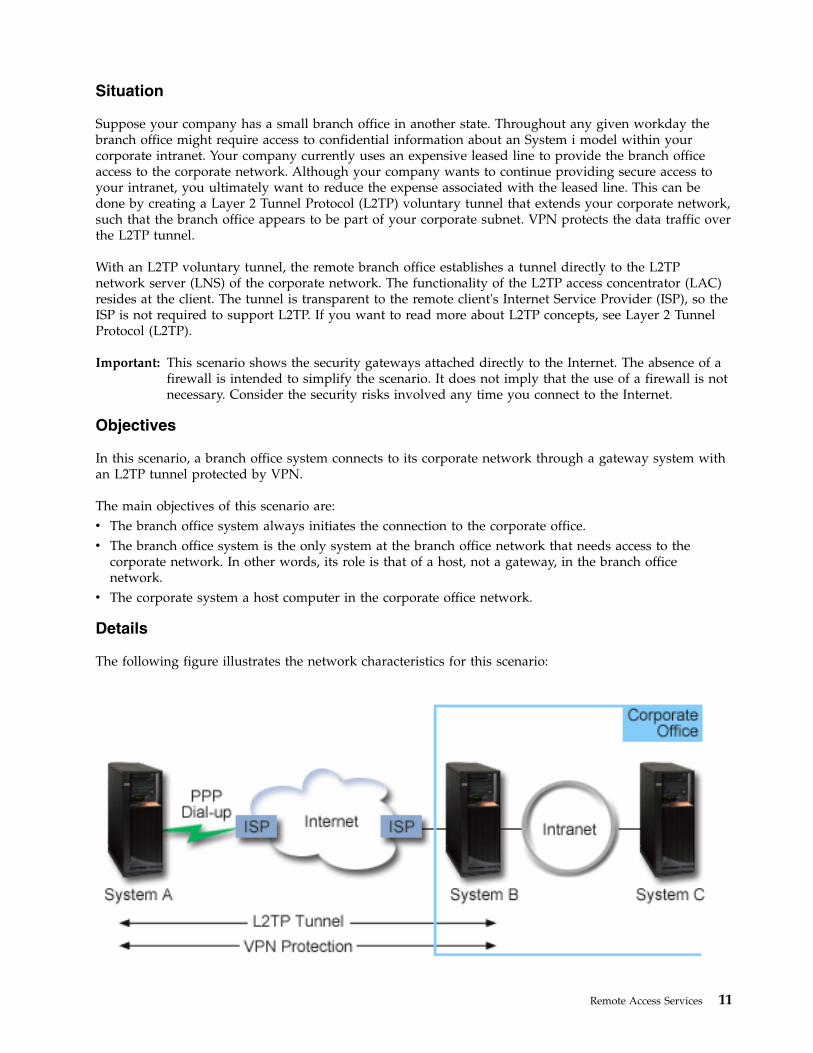
The following figure illustrates the network characteristics for this scenario:
Remote Access Services 11
System A
v Must have access to TCP/IP applications on all systems in the corporate network.v Receives dynamically assigned IP addresses from its ISP.v Must be configured to provide L2TP support.
System B
v Must have access to TCP/IP applications on System A.v Subnet is 10.6.0.0 with mask 255.255.0.0. This subnet represents the data endpoint of the VPN tunnel at
the corporate site.v Connects to the Internet with IP address 205.13.237.6. This is the connection endpoint. That is, System
B performs key management and applies IPSec to incoming and outgoing IP datagrams. System Bconnects to its subnet with IP address 10.6.11.1.
In L2TP terms, System A acts as the L2TP initiator, while System B acts as the L2TP terminator.
Configuration tasks
Assuming that TCP/IP configuration already exists and works, you must complete the following tasks:
Configuring VPN on System AComplete the following steps to configure a VPN connection on System A.
Use the information from your planning worksheets to configure VPN on System A as follows:1. Configure the Internet Key Exchange policy
a. In System i Navigator, expand System A > Network > IP Policies > Virtual Private Networking >IP Security Policies.
b. Right-click Internet Key Exchange Policies and select New Internet Key Exchange Policy.c. On the Remote Server page, select Version 4 IP address as the identifier type and then enter
205.13.237.6 in the IP address field.d. On the Associations page, select Preshared key to indicate that this connection uses a preshared
key to authenticate this policy.e. Enter the preshared key in the Key field. Treat your preshared key like a password.f. Select Key Identifier for the local key server identifier type, and then enter the key identifier in the
Identifier field. For example, thisisthekeyid. Remember that the local key server has adynamically assigned IP address which is impossible to know in advance. System B uses thisidentifier to identify the System A when System A initiates a connection.
g. On the Transforms page, click Add to add the transforms that System A proposes to System B forkey protection and to specify whether the IKE policy uses identity protection when initiatingphase 1 negotiations.
h. On the IKE Policy Transform page, select Preshared key for your authentication method, SHA foryour hash algorithm, and 3DES-CBC for your encryption algorithm. Accept the default values forDiffie-Hellman group and Expire IKE keys after.
i. Click OK to return to the Transforms page.j. Select IKE aggressive mode negotiation (no identity protection).
Note: If you use preshared keys and aggressive mode negotiation together in your configuration,select obscure passwords that are unlikely to be cracked in attacks that scan the dictionary. Itis also recommended you periodically change your passwords.
k. Click OK to save your configurations.2. Configure the data policy
a. From the VPN interface, right-click Data policies and select New Data Policy
12 IBM i: Networking Remote Access Services

b. On the General page, specify the name of the data policy. For example, l2tpremoteuserc. Go to the Proposals page. A proposal is a collection of protocols that the initiating and responding
key servers use to establish a dynamic connection between two endpoints. You can use a singledata policy in several connection objects. However, not all remote VPN key servers necessarilyhave the same data policy properties. Therefore, you can add several proposals to one data policy.When establishing a VPN connection to a remote key server, there must be at least one matchingproposal in the data policy of the initiator and the responder.
d. Click Add to add a data policy transforme. Select Transport for the encapsulation mode.f. Click OK to return to the Transforms page.g. Specify a key expiration value.h. Click OK to save your new data policy.
3. Configure the dynamic-key group
a. From the VPN interface, expand Secure Connections.b. Right-click By Group and select New Dynamic-Key Group.c. On the General page, specify a name for the group. For example, l2tptocorp.d. Select Protects a locally initiated L2TP tunnel.e. For system role, select Both systems are hosts.f. Go to the Policy page. Select the data policy you created in the stepConfigure the data policy,
l2tpremoteuser, from the Data policy drop-down list.g. Select Local system initiates connection to indicate that only System A can initiate connections
with System B.h. Go to the Connections page. Select Generate the following policy filter rule for this group. Click
Edit to define the parameters of the policy filter.i. On the Policy Filter- Local Addresses page, select Key Identifier for the identifier type.j. For the identifier, select the key identifier, thisisthekeyid, that you defined in the IKE policy.k. Go the Policy Filter - Remote Addresses page. Select IP version 4 address from the Identifier
type drop-down list.l. Enter 205.13.237.6 in the Identifier field.m. Go to the Policy Filter - Services page. Enter 1701 in the Local Port and Remote Port fields. Port
1701 is the well-known port for L2TP.n. Select UDP from the Protocol drop-down list.o. Click OK to return to the Connections page.p. Go to the Interfaces page. Select any line or PPP profile to which this group will apply. You have
not created the PPP profile for this group yet. After you do so, you will need to edit the propertiesof this group so that the group applies to the PPP profile you create in the next step.
q. Click OK to create the dynamic-key group, l2tptocorp.4. Configure the dynamic-key connection
a. From the VPN interface, expand By Group. This displays a list of all dynamic-key groups youhave configured on System A.
b. Right-click l2tptocorp and select New Dynamic-Key Connection.c. On the General page, specify an optional description for the connection.d. For the remote key server, select Version 4 IP address for the identifier type.e. Select 205.13.237.6 from the IP address drop-down list.f. Deselect Start on-demand.g. Go to the Local Addresses page. Select Key identifier for the identifier type and then select
thisisthekeyid from the Identifier drop-down list.h. Go to the Remote Addresses page. Select IP version 4 address for the identifier type.
Remote Access Services 13
i. Enter 205.13.237.6 in the Identifier field.j. Go to the Services page. Enter 1701 in the Local Port and Remote Port fields. Port 1701 is the
well-known port for L2TP.k. Select UDP from the Protocol drop-down listl. Click OK to create the dynamic-key connection.
Configuring a PPP connection profile and virtual line on System ANow that a VPN connection is configured on System A you need to create the PPP profile for System A.The PPP profile has no physical line associated with it; instead, it uses a virtual line. This is because thePPP traffic tunnels through the L2TP tunnel, while VPN protects the L2TP tunnel.
Follow these steps to create a PPP connection profile for System A:1. In System i Navigator, expand System A > Network > Remote Access Services.2. Right-click Originator Connection Profiles and select New Profile.3. On the Setup page, select PPP for the protocol type.4. For Mode selections, select L2TP (virtual line).5. Select Initiator on-demand (voluntary tunnel) from the Operating mode drop-down list.6. Click OK to go to the PPP profiles properties pages.7. On the General page, enter a name that identifies the type and the destination of the connection. In
this case, enter toCORP. The name you specify must be 10 characters, or less.8. Optional: Specify a description for the profile.9. Go to the Connection page.
10. In the Virtual line name field, select tocorp from the drop-down list. Remember that this line has noassociated physical interface. The virtual line describes various characteristics of this PPP profile; forexample, the maximum frame size, authentication information, the local host name, and so on. TheL2TP Line Properties dialog box opens.
11. On the General page, enter a description for the virtual line.12. Go to the Authentication page.13. In the Local host name field, enter the host name of the local key server, SystemA.14. Click OK to save the new virtual line description and return to the Connection page.15. Enter the remote tunnel endpoint address, 205.13.237.6, in the Remote tunnel endpoint address
field.16. Select Requires IPSec Protection and select the dynamic-key group you created in previous step
“Configuring VPN on System A” on page 12, l2tptocorp from the Connection group namedrop-down list.
17. Go to the TCP/IP Settings page.18. In the Local IP address section, select Assigned by remote system.19. In the Remote IP address section, select Use fixed IP address. Enter 10.6.11.1, which is the remote
system's IP address in its subnet.20. In the routing section, select Define additional static routes and click Routes. If there is no routing
information provided in the PPP profile, then System A is only able to reach the remote tunnelendpoint but not any other system on the 10.6.0.0 subnet.
21. Click Add to add a static route entry.22. Enter the subnet, 10.6.0.0, and the subnet mask, 255.255.0.0 to route all 10.6.*.* traffic through the
L2TP tunnel.23. Click OK to add the static route.24. Click OK to close the Routing dialog box.25. Go to the Authentication page to set the user name and password for this PPP profile.
14 IBM i: Networking Remote Access Services
26. In the Local system identification section, select Allow the remote system to verify the identity ofthis system.
27. Under Authentication protocol to use select Require encrypted password (CHAP-MD5).In theLocal system identification section, select Allow the remote system to verify the identity of thissystem.
28. Enter the user name, SystemA, and a password.29. Click OK to save the PPP profile.
Applying the l2tptocorp dynamic-key group to the toCorp PPP profileAfter you have your PPP connection profile configured, you need to go back to the dynamic-key group,l2tptocorp, you created and associate it with the PPP profile.
To associate your dynamic-key group with your PPP profile follow these steps:1. In System i Navigator, expand your system > Network > IP Policies > Virtual Private Networking >
Secure Connections > By Group.2. Right-click the dynamic-key group, l2tptocorp, and select Properties.3. Go to the Interfaces page and select Apply this group for the PPP profile you created in
“Configuring a PPP connection profile and virtual line on System A” on page 14, toCorp.4. Click OK to apply l2tptocorp to the PPP profile, toCorp.
Configuring VPN on System BTo configure a VPN connection on System B follow the same steps you used to configure a VPNconnection on System A, and change IP addresses and identifiers as necessary.
Take these other points into consideration before you begin:v The identify the remote key server by the key identifier you specified for the local key server on
System A. For example, thisisthekeyid.v Use the exact same preshared key.v Make sure your transforms match the ones you configured on System A, or connections will fail.v Do not specify Protects a locally initiated L2TP tunnel on the General page of the dynamic-key
group.v Remote system initiates the connection.v Specify that the connection should start on-demand.
Configuring a PPP connection profile and virtual line on System BNow that a VPN connection is configured on System B you need to create the PPP profile for System B.The PPP profile has no physical line associated with it; instead, it uses a virtual line. This is because thePPP traffic tunnels through the L2TP tunnel, while VPN protects the L2TP tunnel.
Follow these steps to create a PPP connection profile for System B:1. In System i Navigator, expand System B > Network > Remote Access Services.2. Right-click Responder Connection Profiles and select New Profile.3. On the Setup page, select PPP for the protocol type.4. For Mode selections, select L2TP (virtual line).5. Select Terminator (network server) from the Operating mode drop-down list.6. Click OK to PPP profiles properties pages.7. On the General page, enter a name that identifies the type and the destination of the connection. In
this case, enter tobranch. The name you specify must be 10 characters, or less.8. Optional: Specify a description for the profile9. Go to the Connection page.
Remote Access Services 15
10. Select the IP address of the local tunnel endpoint, 205.13.237.6.11. In the Virtual line name field, select tobranch from the drop-down list. Remember that this line has
no associated physical interface. The virtual line describes various characteristics of this PPP profile;for example, the maximum frame size, authentication information, the local host name, and so on.The L2TP Line Properties dialog box opens.
12. On the General page, enter a description for the virtual line.13. Go to the Authentication page14. In the Local host name field, enter the host name of the local key server, SystemB.15. Click OK to save the new virtual line description and return to the Connection page.16. Go to the TCP/IP Settings page.17. In the Local IP address section, select the fixed IP address of the local system, 10.6.11.1.18. In the Remote IP address section, select Address pool as the address assignment method. Enter a
starting address, and then specify the number of addresses that can be assigned to the remotesystem.
19. Select Allow remote system to access other networks (IP forwarding).20. Go to the Authentication page to set the user name and password for this PPP profile.21. In the Local system identification section, select Allow the remote system to verify the identity of
this system. This opens the Local System Identification dialog box.22. Under Authentication protocol to use select Require encrypted password (CHAP-MD5).23. Enter the user name, SystemB, and a password.24. Click OK to save the PPP profile.
Activating packet rulesThe VPN wizard automatically creates the packet rules that this connection requires to work properly.However, you must activate them on both systems before you can start the VPN connection.
To activate packet rules on System A, follow these steps:1. In System i Navigator, expand System A > Network > IP Policies.2. Right-click Packet Rules and select Activate. This opens the Activate Packet Rules dialog box.3. Select whether you want to activate only the VPN generated rules, only a selected file, or both the
VPN generated rules and a selected file. You might choose the latter, for instance, if you havemiscellaneous PERMIT and DENY rules that you want to enforce on the interface in addition to theVPN generated rules.
4. Select the interface on which you want the rules activated. In this case, select All interfaces.5. Click OK on the dialog box to confirm that you want to verify and activate the rules on the interface
or interfaces you specified. After you click OK, the system checks the rules for syntax and semanticerrors and reports the results in a message window at the bottom of the editor. For error messagesthat are associated with a specific file and line number, you can right-click the error and select Go ToLine to highlight the error in the file.
6. Repeat these steps to activate packet rules on System B.
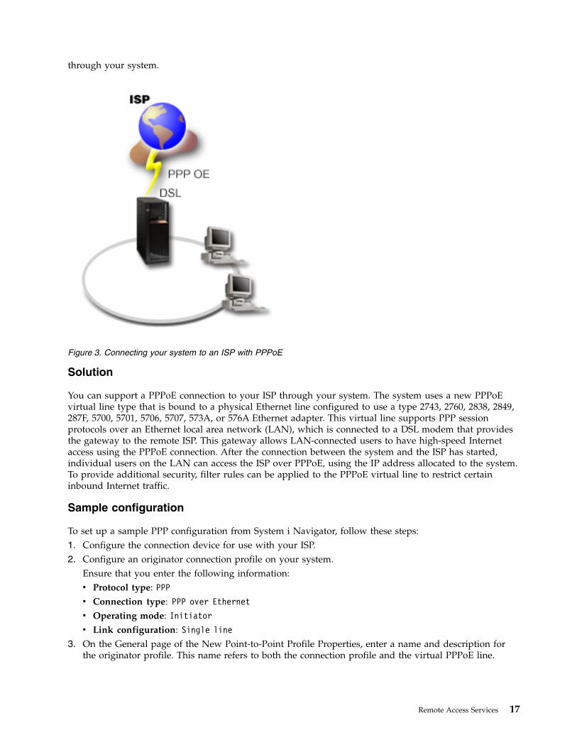
Scenario: Connecting your system to a PPPoE access concentratorMany Internet service providers (ISPs) provide high-speed Internet access over a Digital Subscriber Line(DSL) using Point-to-Point Protocol over Ethernet (PPPoE). You can connect your system to these ISPs toprovide high-bandwidth connections that preserve the benefits of Point-to-Point Protocol (PPP).
Situation
Your business requires a faster Internet connection, so you are interested in a Digital Subscriber Line(DSL) service with a local ISP. After an initial investigation, you find that your ISP uses PPPoE to connectits clients. You need to use this PPPoE connection to provide high-bandwidth Internet connections
16 IBM i: Networking Remote Access Services
through your system.
Solution
You can support a PPPoE connection to your ISP through your system. The system uses a new PPPoEvirtual line type that is bound to a physical Ethernet line configured to use a type 2743, 2760, 2838, 2849,287F, 5700, 5701, 5706, 5707, 573A, or 576A Ethernet adapter. This virtual line supports PPP sessionprotocols over an Ethernet local area network (LAN), which is connected to a DSL modem that providesthe gateway to the remote ISP. This gateway allows LAN-connected users to have high-speed Internetaccess using the PPPoE connection. After the connection between the system and the ISP has started,individual users on the LAN can access the ISP over PPPoE, using the IP address allocated to the system.To provide additional security, filter rules can be applied to the PPPoE virtual line to restrict certaininbound Internet traffic.
Sample configuration
To set up a sample PPP configuration from System i Navigator, follow these steps:1. Configure the connection device for use with your ISP.2. Configure an originator connection profile on your system.
Ensure that you enter the following information:v Protocol type: PPPv Connection type: PPP over Ethernetv Operating mode: Initiatorv Link configuration: Single line
3. On the General page of the New Point-to-Point Profile Properties, enter a name and description forthe originator profile. This name refers to both the connection profile and the virtual PPPoE line.
Figure 3. Connecting your system to an ISP with PPPoE
Remote Access Services 17
4. Click Connection to open the Connection page. Choose the PPPoE virtual line name that correspondsto the name for this connection profile. After you select the line, System i Navigator displays the lineproperties dialog.a. On the General page, enter a meaningful description for the PPPoE virtual line.b. Click Link to open the Link page. From the Physical Line Name select list, select the Ethernet line
that this connection will use, and click Open. Alternately, if you need to define a new Ethernetline, type the line name and click New. System i Navigator displays the Ethernet line propertiesdialog.
Note: PPPoE requires a type 2743, 2760, 2838, 2849, 287F, 5700, 5701, 5706, 5707, 573A, or 576AEthernet adapter.
1) On the General page, enter a meaningful description for the Ethernet Line, and verify that theline definition is using the required hardware resources.
2) Click Link to open the Link page. Enter the properties for the physical Ethernet line. Refer tothe documentation for your Ethernet adapter and the online help for more information.
3) Click Other to open the Other page. Specify the level of access and authority other users mighthave for this line.
4) Click OK to return to the PPPoE virtual line properties page.c. Click Limits to define properties for LCP authentication, or click OK to return to New
Point-to-Point Profile Connection page.d. When you return to the Connection page, specify the PPPoE server addressing based on
information provided by your ISP.5. If your ISP requires the system to authenticate itself or if you want the system to authenticate the
remote system, click Authentication to open the Authentication page and enter the requestedinformation.
6. Click TCP/IP Settings to open the TCP/IP page, and specify the IP address handling parameters forthis connection profile. The setting to be used should be provided by your ISP. To allow LANattached users to connect to the ISP using the IP addresses allocated to the system, select Hideaddresses (Full masquerading).
7. Click DNS to open the DNS page, enter the IP address of the DNS server provided by the ISP.8. Click OK to complete the profile.Related concepts:“Group policy support” on page 4With group policy support, network administrators can define user-based group policies to manageresources. Individual users can be assigned access control policies when they log on to the Point-to-PointProtocol (PPP) or Layer Two Tunneling Protocol (L2TP) session.Related tasks:“Creating a connection profile” on page 55The first step in configuring a PPP connection between systems is to create a connection profile on thesystem.Related reference:“Link configuration” on page 58Link configuration defines the type of line service that your Point-to-Point Protocol (PPP) connectionprofile uses to establish a connection.“System authentication” on page 52PPP connections with a System i platform support several options for authenticating both remote clientsdialing in to the system and connections to an ISP or another system that the system is dialing to.“IP address handling” on page 47Point-to-Point Protocol (PPP) connections enable several different sets of options for managing IPaddresses depending on the type of connection profile.
18 IBM i: Networking Remote Access Services
“IP packet filtering” on page 48IP packet filtering limits the services to individual users when they log on to a network.
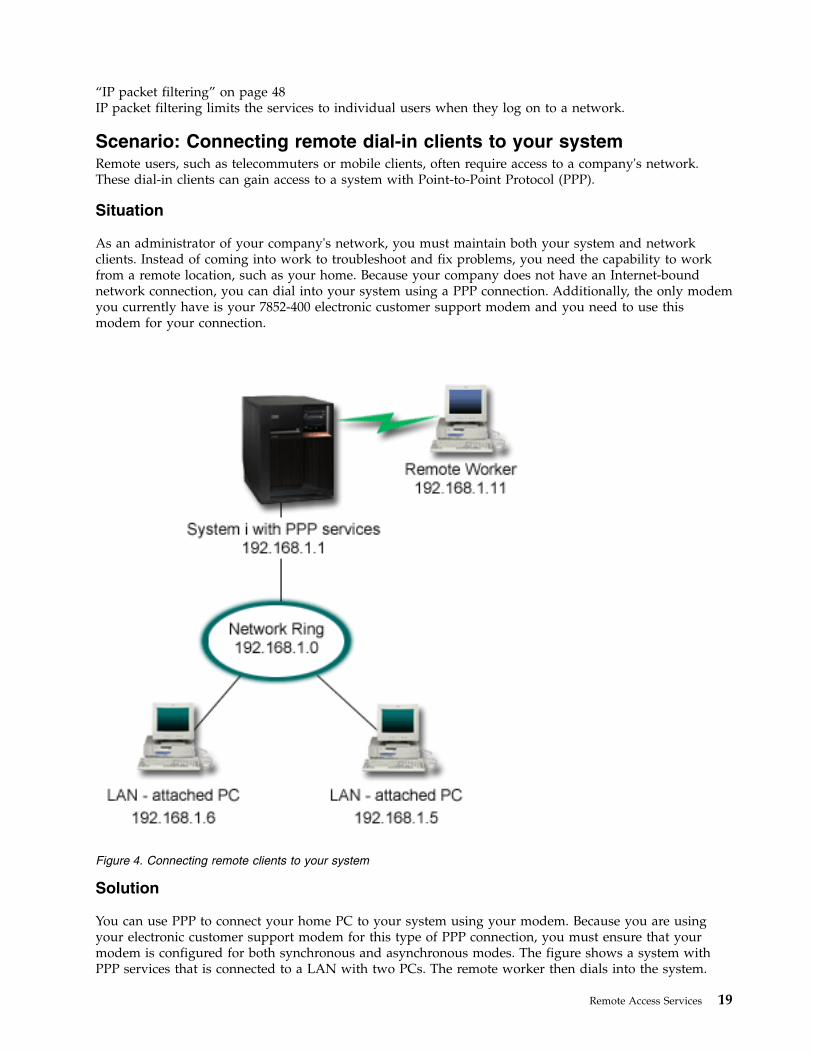
Scenario: Connecting remote dial-in clients to your systemRemote users, such as telecommuters or mobile clients, often require access to a company's network.These dial-in clients can gain access to a system with Point-to-Point Protocol (PPP).
Situation
As an administrator of your company's network, you must maintain both your system and networkclients. Instead of coming into work to troubleshoot and fix problems, you need the capability to workfrom a remote location, such as your home. Because your company does not have an Internet-boundnetwork connection, you can dial into your system using a PPP connection. Additionally, the only modemyou currently have is your 7852-400 electronic customer support modem and you need to use thismodem for your connection.
Solution
You can use PPP to connect your home PC to your system using your modem. Because you are usingyour electronic customer support modem for this type of PPP connection, you must ensure that yourmodem is configured for both synchronous and asynchronous modes. The figure shows a system withPPP services that is connected to a LAN with two PCs. The remote worker then dials into the system.
Figure 4. Connecting remote clients to your system
Remote Access Services 19
The system authenticates itself and becomes part of the work network (192.168.1.0). In this case, it iseasiest to assign a static IP address to the dial-in client.
The remote worker uses Challenge Handshake Authentication Protocol (CHAP-MD5) to authenticate withthe system. The system cannot use MS_CHAP, so you must make sure that your PPP client usesCHAP-MD5.
If you want your remote workers to have access to the company network as implied above, IPforwarding needs to be set on in the TCP/IP stack as well as your PPP receiver profile, and IP routingmust be configured correctly. If you want to limit or secure what actions your remote client can take inyour network, you can use filtering rules to handle their IP packets.
If you want your remote workers to be able to use IPv6 to access the company network, you must alsoenable IPv6 in the connection profile. You do not need to assign a specific IPv6 address. However, if youwant the remote workers to have more than the default link-local IPv6 address assigned, you must eitherconfigure an IPv6 address prefix or set the appropriate options if a DHCPv6 server is available in thecompany network. For this example, we assume that you want to advertise an address prefix of2001:DBA::, a default route, and that a DHCPv6 server in your network is able to provide IP addresses. Aglobal IPv6 address must be configured in the connection profile in order to allow the DHCPv6 server toreturn information to the remote dial-in client.
The preceding figure only has one remote dial-in client, because the electronic customer support modemcan only handle one connection at a time.
Sample configuration
To set up a sample PPP configuration from System i Navigator, follow these steps:1. Configure Dial-up Networking and create a dial-up connection on the remote PC.2. Configure a receiver connection profile on your system.
Ensure that you enter the following information:v Protocol type: PPPv Connection type: Switched-linev Operating mode: Answerv Link configuration: This might be single line, or a line pool, depending on your
environment.
3. On the General page of the New Point-to-Point Profile Properties, enter a name and description forthe receiver profile.
4. Click Connection to open the Connection page. Choose the appropriate Line name, or create a newone by typing a new name, and clicking New.a. On the General page, highlight an existing hardware resource where your 7852–400 adapter is
attached and set the Framing to Asynchronous.b. Click Modem to open the Modem page. From the Name select list, choose the IBM 7852–400
modem.c. Click OK to return to New Point-to-Point Profile Properties page.
5. Click Authentication to open the Authentication page.a. Select Require this iSeries server to verify the identity of the remote system.b. Select Authenticate locally using a validation list and add a new remote user to the validation
list.c. Select Allow encrypted password (CHAP-MD5).
6. Click TCP/IP IPv4 Settings to open the TCP/IP IPv4 Settings page.a. Select Enable IPv4
20 IBM i: Networking Remote Access Services
||||||||
|
|
b. Select the local IP address of 192.168.1.1.c. For the remote IP address, select Fixed IP address with a starting IP address of 192.168.1.11.d. Select Allow remote system to access other networks.
7. Click TCP/IP IPv6 Settings to open the TCP/IPv6 Settings page.a. Select Enable IPv6.b. Specify a global IPv6 address for Fixed local IP address. This address must be compatible with
the DHCPv6 server configuration for distributing IPv6 addresses.c. Select Generate for Interface identifier.d. Select Yes for Allow remote system to access other networks (IP forwarding).e. Set the Address prefix to 2001:DBA::.f. Select Advertise IPv6 default route.g. Select Advertise DHCPv6 and Managed address configuration.
8. Click OK to complete the profile.Related concepts:“Planning PPP” on page 38Planning Point-to-Point Protocol (PPP) includes creating and administering PPP connections.Related tasks:“Creating a connection profile” on page 55The first step in configuring a PPP connection between systems is to create a connection profile on thesystem.Related reference:“Challenge Handshake Authentication Protocol with MD5” on page 52Challenge Handshake Authentication Protocol (CHAP-MD5) uses an algorithm (MD-5) to calculate avalue that is known only to the authenticating system and the remote device.“Link configuration” on page 58Link configuration defines the type of line service that your Point-to-Point Protocol (PPP) connectionprofile uses to establish a connection.“Line pool” on page 59To set the PPP connection to use a line from a line pool, select this line service. When the PPP connectionstarts, the system selects an unused line from the line pool. For dial on-demand profiles, the system doesnot select the line until it detects TCP/IP traffic for the remote system.
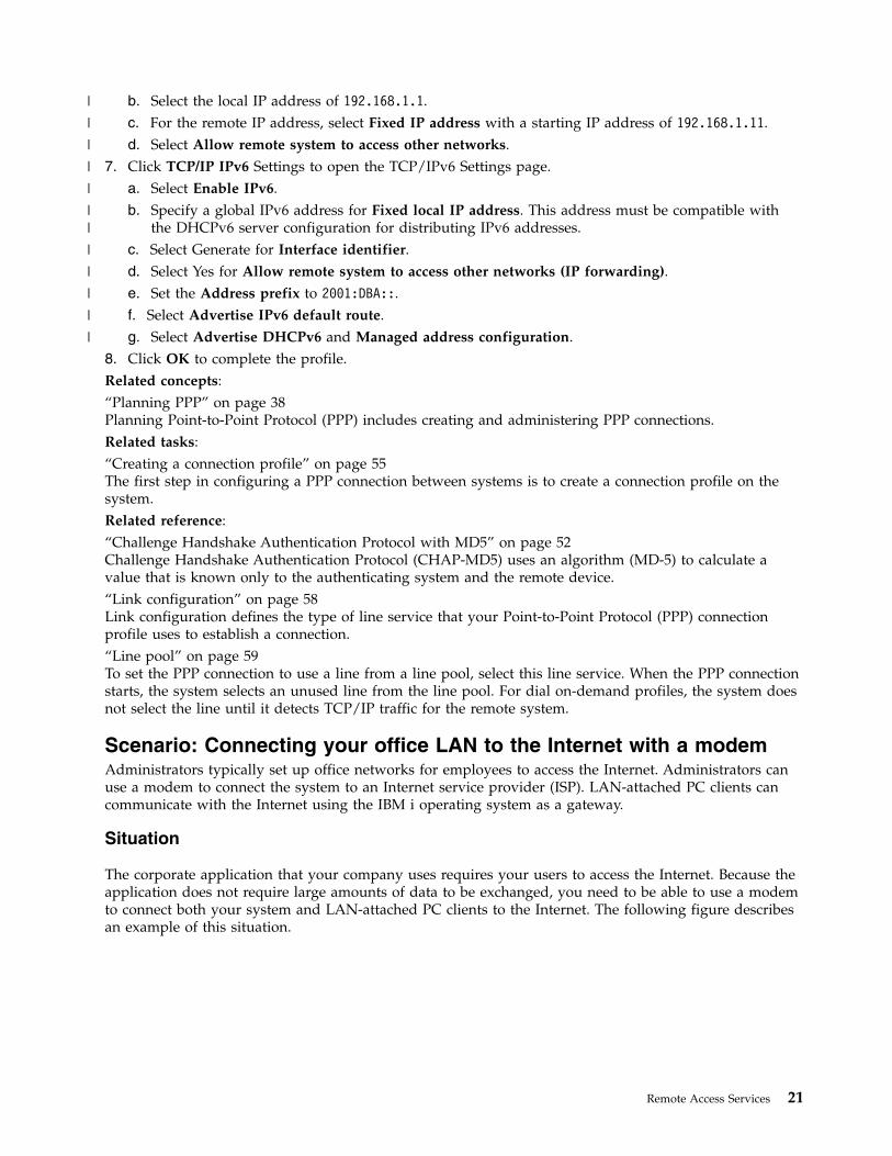
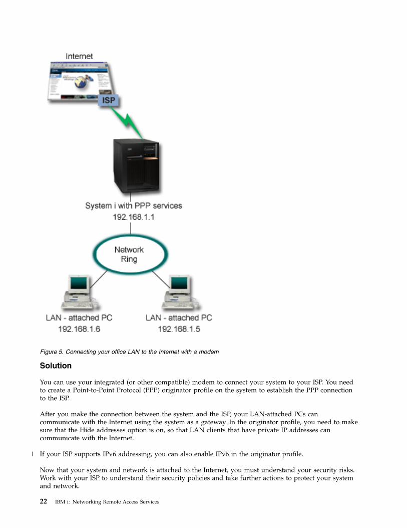
Scenario: Connecting your office LAN to the Internet with a modemAdministrators typically set up office networks for employees to access the Internet. Administrators canuse a modem to connect the system to an Internet service provider (ISP). LAN-attached PC clients cancommunicate with the Internet using the IBM i operating system as a gateway.
Situation
The corporate application that your company uses requires your users to access the Internet. Because theapplication does not require large amounts of data to be exchanged, you need to be able to use a modemto connect both your system and LAN-attached PC clients to the Internet. The following figure describesan example of this situation.
Remote Access Services 21
|
|
|
|
|
||
|
|
|
|
|
Solution
You can use your integrated (or other compatible) modem to connect your system to your ISP. You needto create a Point-to-Point Protocol (PPP) originator profile on the system to establish the PPP connectionto the ISP.
After you make the connection between the system and the ISP, your LAN-attached PCs cancommunicate with the Internet using the system as a gateway. In the originator profile, you need to makesure that the Hide addresses option is on, so that LAN clients that have private IP addresses cancommunicate with the Internet.
If your ISP supports IPv6 addressing, you can also enable IPv6 in the originator profile.
Now that your system and network is attached to the Internet, you must understand your security risks.Work with your ISP to understand their security policies and take further actions to protect your systemand network.
Figure 5. Connecting your office LAN to the Internet with a modem
22 IBM i: Networking Remote Access Services
|
Depending on your Internet usage, bandwidth might become a concern.
Sample configuration
To set up a sample configuration from System i Navigator, follow these steps:1. Configure an originator connection profile on your system.
Ensure that you select the following information:v Protocol type: PPPv Connection type: Switched-linev Operating mode: Dialv Link configuration: This might be single line, or line pool, depending on your environment.
2. On the General page of the New Point-to-Point Profile Properties, enter a name and description forthe originator profile.
3. Click Connection to open the Connection page. Choose the appropriate Line name or create a newone by typing a new name and clicking New.a. On the General page of the new line properties, highlight an existing hardware resource. If you
select an internal modem resource, then the modem type and framing type settings will beautomatically selected.
b. Click OK to return to New Point-to-Point Profile Properties page.4. Click Add, and type the telephone number to dial to reach the ISP server. Ensure that you include
any required prefix.5. Click Authentication to open the Authentication page, select Allow the remote system to verify the
identity of this iSeries server. Select the authentication protocol, and enter any required user name orpassword information.
6. Click TCP/IP IPv4 Settings to open the TCP/IP IPv4 page.a. Select Enable IPv4.b. Select Assigned by remote system for both local and remote IP addresses.c. Select Add remote system as the default route.d. Check Hide addresses so that your internal IP addresses are not routed on to the Internet.
7. If you want to enable IPv6 addressing, click TCP/IP IPv6 Settings to open the TCP/IP IPv6 page.a. Select Enable IPv6.b. b. Select *None for Fixed local IP address.c. Select Generate for Interface identifier.d. Select No for Allow remote system to access other networks (IP forwarding).e. Select Accept a default route.
8. Click DNS to open the Domain Name System (DNS) page, enter the IP address of the DNS serverthat is provided by the ISP.
9. Click OK to complete the profile.
To use the connection profile to connect to the Internet, right-click the connection profile from System iNavigator, and select Start. The connection is successful when the status changes to Active. Refresh toupdate the display.
Note: You must also ensure that the other systems in your network have proper routing defined, so thatInternet bound TCP/IP traffic from these systems is sent through the system.
Related concepts:“Planning PPP” on page 38Planning Point-to-Point Protocol (PPP) includes creating and administering PPP connections.Related tasks:
Remote Access Services 23
|
|
|
|
|
|
|
|
|
|
|
“Creating a connection profile” on page 55The first step in configuring a PPP connection between systems is to create a connection profile on thesystem.Related reference:“Line pool” on page 59To set the PPP connection to use a line from a line pool, select this line service. When the PPP connectionstarts, the system selects an unused line from the line pool. For dial on-demand profiles, the system doesnot select the line until it detects TCP/IP traffic for the remote system.“Link configuration” on page 58Link configuration defines the type of line service that your Point-to-Point Protocol (PPP) connectionprofile uses to establish a connection.
Scenario: Connecting your corporate and remote networks with amodemA modem enables two remote locations (such as a central office and a branch office) to exchange databetween them. Point-to-Point Protocol (PPP) can connect two LANs together by establishing a connectionbetween a system in the central office and another one in the branch office.
Situation
Suppose that you have a branch and corporate networks in two different locations. Every day the branchoffice needs to connect with the corporate office to exchange database information for their data entryapplications. The amount of data exchanged does not constitute the purchase of a physical networkconnection, so you decide to use modems to connect the two networks as required.
24 IBM i: Networking Remote Access Services
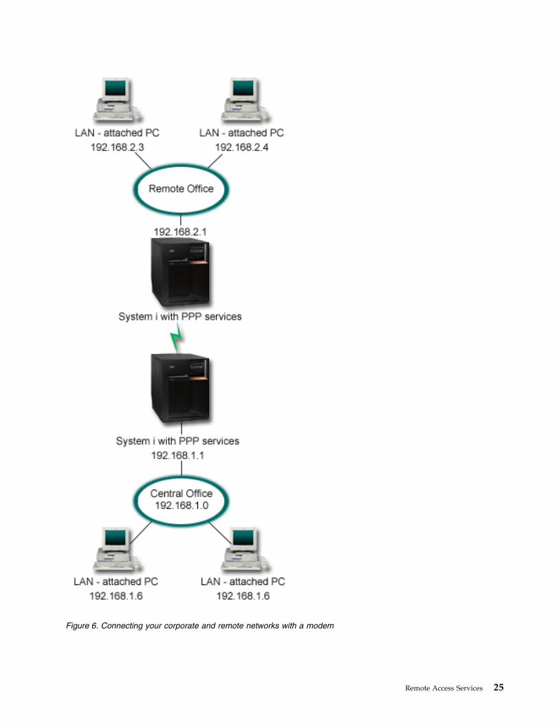
Figure 6. Connecting your corporate and remote networks with a modem
Remote Access Services 25
Solution
PPP can connect two LANs together by establishing a connection between the systems as shown in thefigure. In this case, assume that the remote office initiates the connection to the central office. Youconfigure an originator profile on the remote system and a receiver profile on the central office system.
If the remote office PCs need access to the corporate LAN (192.168.1.0), the central office receiver profilewill need IP forwarding turned on and IP address routing should be enabled for the PCs (192.168.2,192.168.3, 192.168.1.6, and 192.168.1.5 in this example). Also, IP forwarding for the TCP/IP stack must beactivated. This configuration enables basic TCP/IP communication between the LANs. You shouldconsider security factors and DNS to resolve host names between the LANs.
You can also configure IPv6 access for the remote office PCs by enabling IP forwarding in the TCP/IPIPv6 Settings section of the connection profiles. IP forwarding for the TCP/IP stack must also beactivated. However, even though IP forwarding is enabled, the Router Advertisement messages on thePPP link cannot be used to provide an address prefix to the PCs on either of the LANs. The reason isbecause the Router Advertisement messages are local to the PPP link. Therefore, IPv6 address assignmentfor the PCs is not affected by configuration in the PPP connection profiles.
Sample configuration
To set up a sample configuration from System i Navigator, follow these steps:1. Configure an originator connection profile on the remote office system.
Ensure that you select the following information:v Protocol type: PPPv Connection type: Switched-linev Operating mode: Dialv Link configuration: This might be single line, or line pool, depending on your
environment.
2. On the General page of the New Point-to-Point Profile Properties, enter a name and description forthe originator profile.
3. Click Connection to open the Connection page. Choose the appropriate Line name or create a newone by typing a new name and clicking New.a. On the General page of the new line properties, highlight an existing hardware resource and set
the Framing to Asynchronous.b. Click Modem to open the Modem page. From the Name select list, choose the modem that you
are using.c. Click OK to return to New Point-to-Point Profile Properties page.
4. Click Add and type the telephone number to reach the central office system. Ensure that you includeany required prefixes.
5. Click Authentication to open the Authentication page, and select Allow the remote system to verifythe identity of this iSeries server. Select Require encrypted password (CHAP-MD5), and enter therequired user name and password information.
6. Click TCP/IP IPv4 Settings to open the TCP/IP IPv4 Settings page.a. Select Enable IPv4.b. For Local IP address, select the IP address of the remote office LAN interface (192.168.2.1) from
the Use fixed IP address select box.c. For the remote IP address, choose Assigned by remote system.d. In the routing section, select Add remote system as the default route.
7. Click TCP/IP IPv6 Settings to open the TCP/IP IPv6 Settings page.a. Select Enable IPv6.
26 IBM i: Networking Remote Access Services
||||||
|
|
||
|
|
|
|

b. Select Generate for Interface identifier.c. Select Yes for Allow remote system to access other networks (IP forwarding).d. Select *None for Address prefix.e. Do not select Advertise IPv6 default route or Advertise DHCPv6.f. Add the appropriate IPv6 routes.
8. Click DNS to open the DNS settings page.a. Enter one of the following options:v The IP address or host name for a DNS server on the corporate LAN.v Select None if you do not want to add any DNS servers when the connection is established.
9. Click OK to complete the originator profile.10. Configure a receiver connection profile on the central office system.
Ensure that you select the following information:v Protocol type: PPPv Connection type: Switched-linev Operating mode: Answerv Link configuration: This might be single line, or line pool, depending on your
environment.
11. On the General page of the New Point-to-Point Profile Properties, enter a name and description forthe receiver profile.
12. Click Connection to open the Connection page. Choose the appropriate Line name or create a newone by typing a new name and clicking New.a. On the General page, highlight an existing hardware resource and set the Framing to
Asynchronous.b. Click Modem to open the Modem page. From the Name select list, choose the modem that you
are using.c. Click OK to return to New Point-to-Point Profile Properties page.
13. Click Authentication to open the Authentication page.a. Check Require this iSeries server to verify the identity of the remote system.b. Add a new remote user to the validation list.c. Check the CHAP-MD5 authentication.
14. Click TCP/IP IPv4 Settings to open the TCP/IP IPv4 Settings page.a. Select Enable IPv4.b. For the local IP address, select the IP address of the central office interface (192.168.1.1) from the
select box.c. For the remote IP address, select Based on remote system's user ID. The IP Addresses Defined
By User Name dialog will appear. Click Add. Fill in the fields for Caller user name, IP address,and Subnet mask. In our scenario, the following will be appropriate:v Caller user name: Remote_sitev IP address: 192.168.2.1v Subnet mask: 255.255.255.0
Click OK, and click OK again to return to the TCP/IP Settings page.d. Select IP forwarding to enable other systems in the network to use this system as a gateway.
15. Click TCP/IP IPv6 Settings to open the TCP/IP IPv6 Settings page.a. Select Enable IPv6.b. Select Generate for Interface identifier.c. Select Yes for Allow remote system to access other networks (IP forwarding).
Remote Access Services 27
|
|
|
|
|
|
|
|
|
|
|
|
||
|||
|
|
|
|
|
|
|
|
|
d. Select *None for Address prefix.e. Do not select Advertise IPv6 default route or Advertise DHCPv6.f. Add the appropriate IPv6 routes.
16. Click OK to complete the receiver profile.Related tasks:“Creating a connection profile” on page 55The first step in configuring a PPP connection between systems is to create a connection profile on thesystem.Related reference:“Link configuration” on page 58Link configuration defines the type of line service that your Point-to-Point Protocol (PPP) connectionprofile uses to establish a connection.“Line pool” on page 59To set the PPP connection to use a line from a line pool, select this line service. When the PPP connectionstarts, the system selects an unused line from the line pool. For dial on-demand profiles, the system doesnot select the line until it detects TCP/IP traffic for the remote system.
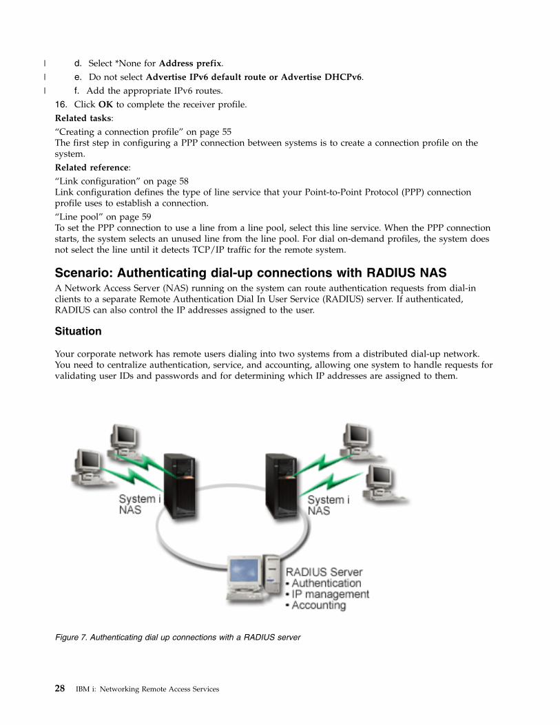
Scenario: Authenticating dial-up connections with RADIUS NASA Network Access Server (NAS) running on the system can route authentication requests from dial-inclients to a separate Remote Authentication Dial In User Service (RADIUS) server. If authenticated,RADIUS can also control the IP addresses assigned to the user.
Situation
Your corporate network has remote users dialing into two systems from a distributed dial-up network.You need to centralize authentication, service, and accounting, allowing one system to handle requests forvalidating user IDs and passwords and for determining which IP addresses are assigned to them.
Figure 7. Authenticating dial up connections with a RADIUS server
28 IBM i: Networking Remote Access Services
|
|
|
Solution
When users attempt to connect, the NAS running on the systems forwards the authentication informationto a RADIUS server on the network. The RADIUS server, which maintains all authentication informationfor your network, processes the authentication request and responds. If the user is validated, the RADIUSserver can also be configured to assign the peers's IP address, and can activate accounting to track useractivity and usage. To support RADIUS, you must define the RADIUS NAS server on the system.
Sample configuration
To set up a sample configuration from System i Navigator, follow these steps:1. In System i Navigator, expand Network, right-click Remote Access Services and select Services.2. On the RADIUS tab, select Enable RADIUS Network Access Server connection, and Enable
RADIUS for authentication. Depending on your RADIUS solution, you can also choose to haveRADIUS handle connection accounting and TCP/IP address configuration.
3. Click the RADIUS NAS settings button.4. On the General page, enter a description for this server.5. On the Authentication Server (and optionally Accounting Server) pages, click Add and enter the
following information:a. In the Local IP address box, enter the IP address for the interface that is used to connect to the
RADIUS server.b. In the Server IP address box, enter the IP address for the RADIUS server.c. In the Password box, enter the password that is used to identify the system to the RADIUS
server.d. In the Port box, enter the port on the system that is used to communicate with the RADIUS
server. The defaults are port 1812 for the authentication server or 1813 for the accounting server.6. Click OK.7. In System i Navigator, expand Network > Remote Access Services.8. Select the Connection profile that will use the RADIUS server for authentication. RADIUS services
are only applicable for receiver connection profiles.9. On the Authentication page, select Require this iSeries server to verify the identity of the remote
system.10. Select Authenticate remotely using a RADIUS server.11. Select the authentication protocol. (PAP, or CHAP-MD5) This protocol must also be used by the
RADIUS server.12. Select Use RADIUS for connection editing and accounting.13. Click OK to save the change to the connection profile.
You must also setup the RADIUS server, including support for the authentication protocol, user data,passwords, and accounting information. Refer to your RADIUS vendor for more information.
When users dial in using this connection profile, the system forwards the authentication information tothe specified RADIUS server. If the user is validated, the connection is allowed, and uses any connectionrestrictions specified in the user's information about the RADIUS server.Related tasks:“Enabling RADIUS and DHCP services for connection profiles” on page 69Here are the steps for enabling RADIUS or Dynamic Host Configuration Protocol (DHCP) services forPPP receiver connection profiles.Related reference:“System authentication” on page 52PPP connections with a System i platform support several options for authenticating both remote clients
Remote Access Services 29
dialing in to the system and connections to an ISP or another system that the system is dialing to.“Remote Authentication Dial In User Service overview” on page 53Remote Authentication Dial In User Service (RADIUS) is an Internet standard protocol that providescentralized authentication, accounting and IP management services for remote access users in adistributed dial-up network.
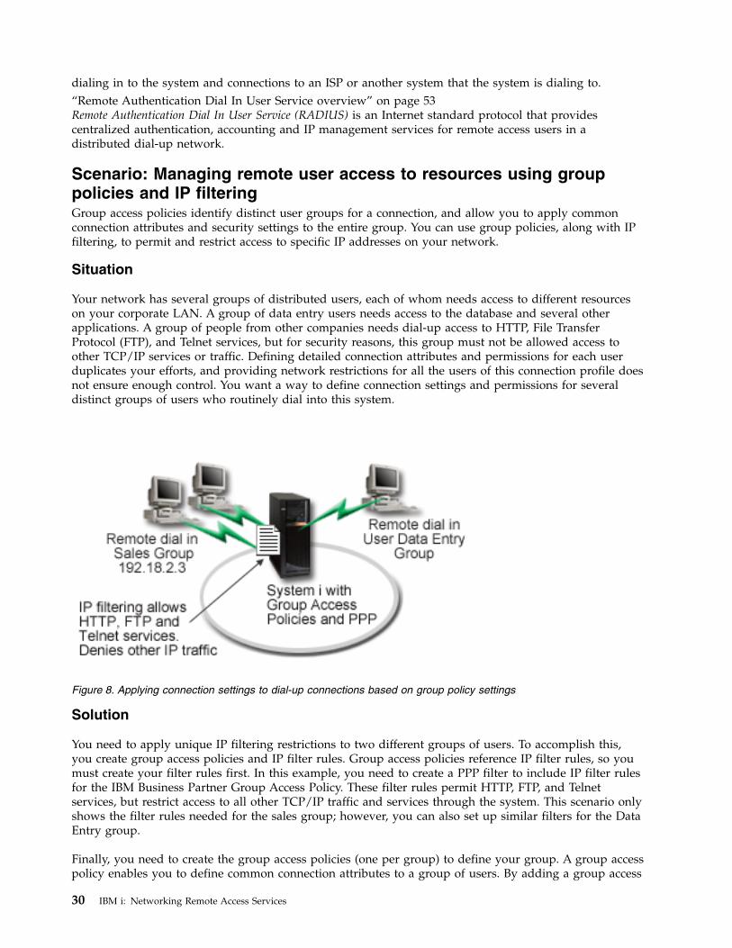
Scenario: Managing remote user access to resources using grouppolicies and IP filteringGroup access policies identify distinct user groups for a connection, and allow you to apply commonconnection attributes and security settings to the entire group. You can use group policies, along with IPfiltering, to permit and restrict access to specific IP addresses on your network.
Situation
Your network has several groups of distributed users, each of whom needs access to different resourceson your corporate LAN. A group of data entry users needs access to the database and several otherapplications. A group of people from other companies needs dial-up access to HTTP, File TransferProtocol (FTP), and Telnet services, but for security reasons, this group must not be allowed access toother TCP/IP services or traffic. Defining detailed connection attributes and permissions for each userduplicates your efforts, and providing network restrictions for all the users of this connection profile doesnot ensure enough control. You want a way to define connection settings and permissions for severaldistinct groups of users who routinely dial into this system.
Solution
You need to apply unique IP filtering restrictions to two different groups of users. To accomplish this,you create group access policies and IP filter rules. Group access policies reference IP filter rules, so youmust create your filter rules first. In this example, you need to create a PPP filter to include IP filter rulesfor the IBM Business Partner Group Access Policy. These filter rules permit HTTP, FTP, and Telnetservices, but restrict access to all other TCP/IP traffic and services through the system. This scenario onlyshows the filter rules needed for the sales group; however, you can also set up similar filters for the DataEntry group.
Finally, you need to create the group access policies (one per group) to define your group. A group accesspolicy enables you to define common connection attributes to a group of users. By adding a group access
Figure 8. Applying connection settings to dial-up connections based on group policy settings
30 IBM i: Networking Remote Access Services
policy to a validation list on the system, you can apply these connection settings during theauthentication process. The group access policy specifies several settings for the user's session, includingthe ability to apply IP filtering rules that restrict the IP addresses and TCP/IP services available to a userduring the session.
Sample configuration
To set up a sample configuration from System i Navigator, follow these steps:1. Create the Point-to-Point Protocol (PPP) filter identifier and IP packet rules filters that specify the
permissions and restrictions for this group access policy.a. In System i Navigator, expand Network > Remote Access Services.b. Click Receiver Connection Profiles, and select Group Access Policies.c. Right-click a predefined group listed in the right pane and select Properties.
Note: If you want to create a new group access policy, right-click Group Access Policies andselect New Group Access Policies. Complete the General tab. Then select the TCP/IPSettings tab and continue with step e below.
d. Select the TCP/IP Settings tab, and click Advanced.e. Select Use IP packet rules for this connection, and click Edit Rules File. This will start the IP
Packet Rules Editor, and open the PPP filters packet rules file.f. Open the Insert menu, and select Filters to add filter sets. Use the General tab to define the filter
sets, and the Services tab to define the service you are permitting, such as HTTP. The followingfilter set, "services_rules," will permit HTTP, FTP and Telnet services. The filter rules include animplicit default deny statement, restricting any TCP/IP services or IP traffic not specificallypermitted.
Note: The IP addresses in the following example are globally routable, and are for examplepurposes only.
###The following 2 filters will permit HTTP (Web browser) traffic in & out of the system.
FILTER SET services_rules ACTION = PERMIT DIRECTION = INBOUND SRCADDR %= * DSTADDR = 192.18.2.3 PROTOCOL = TCP DSTPORT = 80 SRCPORT %= * FRAGMENTS = NONE JRN = OFF
FILTER SET services_rules ACTION = PERMIT DIRECTION = OUTBOUND SRCADDR %= 192.18.2.3 DSTADDR = * PROTOCOL = TCP DSTPORT = * SRCPORT = %80 FRAGMENTS = NONE JRN = OFF
###The following 4 filters will permit FTP traffic in & out of the system.
FILTER SET services_rules ACTION = PERMIT DIRECTION = INBOUND SRCADDR %= * DSTADDR = 192.18.2.3 PROTOCOL = TCP DSTPORT = 21 SRCPORT %= * FRAGMENTS = NONE JRN = OFF
FILTER SET services_rules ACTION = PERMIT DIRECTION = OUTBOUND SRCADDR %= 192.18.2.3 DSTADDR = * PROTOCOL = TCP DSTPORT = * SRCPORT = %21 FRAGMENTS = NONE JRN = OFF
FILTER SET services_rules ACTION = PERMIT DIRECTION = INBOUND SRCADDR %= * DSTADDR = 192.18.2.3 PROTOCOL = TCP DSTPORT = 20 SRCPORT %= * FRAGMENTS = NONE JRN = OFF
FILTER SET services_rules ACTION = PERMIT DIRECTION = OUTBOUND SRCADDR %= 192.18.2.3 DSTADDR = * PROTOCOL = TCP DSTPORT = * SRCPORT = %20 FRAGMENTS = NONE JRN = OFF
###The following 2 filters will permit telnet traffic in & out of the system.
FILTER SET services_rules ACTION = PERMIT DIRECTION = INBOUND SRCADDR %= * DSTADDR = 192.18.2.3 PROTOCOL = TCP DSTPORT = 23 SRCPORT %
Remote Access Services 31
= * FRAGMENTS = NONE JRN = OFF
FILTER SET services_rules ACTION = PERMIT DIRECTION = OUTBOUND SRCADDR %= 192.18.2.3 DSTADDR = * PROTOCOL = TCP DSTPORT = * SRCPORT %= 23 FRAGMENTS = NONE JRN = OFF
g. Open the Insert menu, and select Filter Interface. Use the filter interface to create a PPP filteridentifier, and include the filter sets you've defined.1) On the General tab, enter permitted_services for the PPP filter identifier.2) On the Filter sets tab, select the filter set services_rules, and click Add.3) Click OK. The following line will be added to the rules file:
###The following statement binds (associates) the ’services_rules’ filter set with thePPP filter ID "permitted_services." This PPP filter IDcan then be applied to the physical interface associated with a PPP connection profileor Group Access Policy.
FILTER_INTERFACE PPP_FILTER_ID = permitted_services SET = services_rules
h. Save your changes, and exit. If you need to undo these changes later, use the character-basedinterface to enter the command RMVTCPTBL *ALL. This command removes all filter rules and NATon the system.
i. On the Advanced TCP/IP settings dialog, leave the PPP filter identifier box blank, and click OKto exit. Later, you should apply the filter identifier you just created to a group access policy, notthis connection profile.
2. Define a new group access policy for this user group.a. In System i Navigator, expand Network > Remote Access Services > Receiver Connection
Profiles.b. Right click the Group Access Policy icon, and select New Group Access Policy. System i
Navigator displays the New Group Access Policy definition dialog.c. On the General page, enter a name and description for the group access policy.d. On the TCP/IP settings page:v Select Use IP packet rules for this connection, and select the PPP filter identifier
permitted_services.e. Select OK to save the group access policy.
3. Apply the group access policy to the users associated with this group.a. Open the receiver connection profile controlling these dial-up connections.b. On the Authentication page of the receiver connection profile, select the validation list that
contains the users' authentication information, and click Open.c. Select a user in the Sales group to which you want to apply the group access policy, and click
Open.d. Click Apply a Group Policy to the user, and select the group access policy defined in step 2.e. Repeat for each Sales user.
Related concepts:“Configuring a group access policy” on page 67The Group Access Policies folder under Receiver Connection Profiles provides options for configuringpoint-to-point connection parameters that apply to a group of remote users. It applies only to thosepoint-to-point connections that originate from a remote system and are received by the local system.“Group policy support” on page 4With group policy support, network administrators can define user-based group policies to manageresources. Individual users can be assigned access control policies when they log on to the Point-to-PointProtocol (PPP) or Layer Two Tunneling Protocol (L2TP) session.Related tasks:
32 IBM i: Networking Remote Access Services
“Creating a connection profile” on page 55The first step in configuring a PPP connection between systems is to create a connection profile on thesystem.“Applying IP packet filtering rules to a PPP connection” on page 68You can use a packet rules file to restrict the access of a user or a group to IP addresses on your network.
Related reference:“Validation list” on page 54A validation list is used to store user ID and password information about remote users.“System authentication” on page 52PPP connections with a System i platform support several options for authenticating both remote clientsdialing in to the system and connections to an ISP or another system that the system is dialing to.Related information:IP filtering and network address translation
Scenario: Sharing a modem between logical partitions using L2TPYou have virtual Ethernet set up across four logical partitions. You want selected logical partitions toshare a modem to access an external LAN.
Situation
You are the system administrator at a medium-sized company. It is time to update your computerequipment, but you want to do more than that; you want to streamline your hardware. You start theprocess by consolidating the work of three old systems onto one new system. You create three logicalpartitions on the system. The new system comes with a 2793 internal modem. This is the onlyinput/output processor (IOP) you have that supports Point-to-Point Protocol (PPP). You also have an old7852–400 electronic customer support modem.
Solution
Multiple systems and partitions can share the same modems for dial-up connections, eliminating the needfor each system or partition to have its own modem. This is possible if you use L2TP tunnels andconfigure L2TP profiles that allow outgoing calls. In your network, the tunnels will run over a virtualEthernet network and a physical network. The physical line is connected to another system that sharesthe modems in your network.
Details
The following figure illustrates the network characteristics for this scenario:
Remote Access Services 33
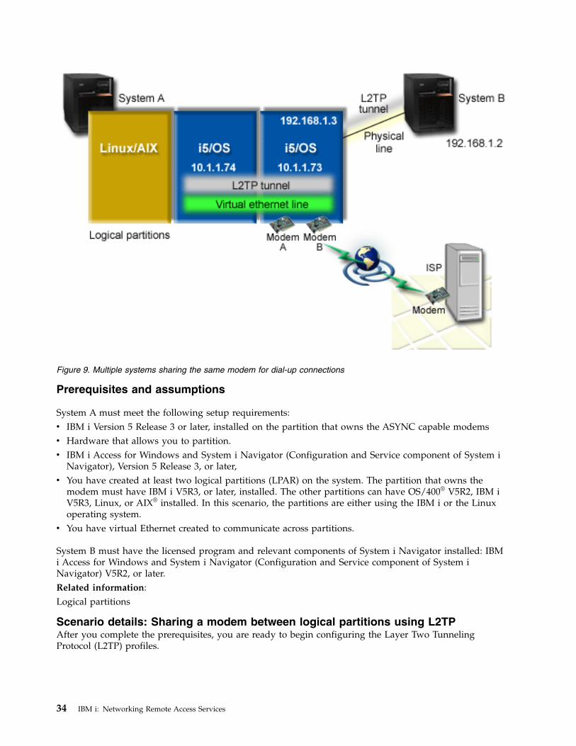
Prerequisites and assumptions
System A must meet the following setup requirements:v IBM i Version 5 Release 3 or later, installed on the partition that owns the ASYNC capable modemsv Hardware that allows you to partition.v IBM i Access for Windows and System i Navigator (Configuration and Service component of System i
Navigator), Version 5 Release 3, or later,v You have created at least two logical partitions (LPAR) on the system. The partition that owns the
modem must have IBM i V5R3, or later, installed. The other partitions can have OS/400® V5R2, IBM iV5R3, Linux, or AIX® installed. In this scenario, the partitions are either using the IBM i or the Linuxoperating system.
v You have virtual Ethernet created to communicate across partitions.
System B must have the licensed program and relevant components of System i Navigator installed: IBMi Access for Windows and System i Navigator (Configuration and Service component of System iNavigator) V5R2, or later.Related information:Logical partitions
Scenario details: Sharing a modem between logical partitions using L2TPAfter you complete the prerequisites, you are ready to begin configuring the Layer Two TunnelingProtocol (L2TP) profiles.
Figure 9. Multiple systems sharing the same modem for dial-up connections
34 IBM i: Networking Remote Access Services
Step 1: Configuring the L2TP terminator profile for any interface on the partition that owns themodems:
To create a terminator profile for any interface, follow these steps:1. In System i Navigator, expand your system > Network > Remote Access Services.2. Right-click Receiver Connection Profiles, and select New Profile.3. Select the following options on the Setup page and click OK:v Protocol type: PPPv Connection type: L2TP (virtual line)v Operating mode: Terminator (network server)v Type of line service: Single line
4. On the New Profile - General tab, complete the following fields:v Name: toExternalv Description: Receiver connection to dial outv Select Start profile with TCP.
5. On the New Profile - Connection tab, complete the following fields.v Local tunnel endpoint IP address: ANYv Virtual line name: toExternal. This line has no associated physical interfaces. The virtual line
describes various characteristics of this PPP profile. After the L2TP Line Properties window opens,click the Authentication tab and enter your system's host name. Click OK to return to theConnection tab on the New PPP Profile Properties window.
6. Click Allow out-going call establishment. The Outgoing call dial properties dialog appears.7. On the Outgoing Call Dial Properties page, select a line service type.v Type of line service: Line poolv Name: dialOutv Click New. The New Line Pool Properties dialog appears.
8. On the New line pool properties window, select the lines and modems to which you will allow theoutgoing calls and click Add. If you need to define these lines, select New Line. The interfaces onthe partition which owns these modems will try to use whichever line is open from this line pool.The new Line Properties window opens.
9. On the New Line Properties - General tab, enter information in the following fields:v Name: line1v Description: first line and first modem for line pool (2793 internal modem)v Hardware resource: cmn03 (communication port)
10. Accept the defaults on all other tabs and click OK to return to the New Line Pool Propertieswindow.
11. On the New Line Pool Properties window, select the lines and modems to which you will allow theoutgoing calls and click Add. Verify the 2793 modem is a selected for the pool.
12. Select New Line again to add the 7852–400 electronic customer support modem. The new LineProperties window opens.
13. On the New Line Properties - General tab, enter information in the following fields:v Name: line2v Description: second line and second modem for line pool (7852-400 external electronic customer
support modem)v Hardware resource: cmn04 (V.24 port)v Framing: Asynchronous
14. On the New Line Properties - Modem tab, select the external modem (7852–400) and click OK toreturn to the New Line Pool Properties window.
Remote Access Services 35
15. Select any other available lines you want to add to the line pool and click Add. In this example,verify the two new modems you added above are listed under the Selected lines for pool field andclick OK to return to the Outgoing Call Dial Properties window.
16. On the Outgoing Call Dial Properties window, enter the Default Dial Numbers and click OK toreturn to the New PPP Profile Properties window.
Note: These numbers might be something like your Internet service provider (ISP) which is going tobe frequently called by the other systems using these modems. If the other systems specify atelephone number of *PRIMARY or *BACKUP, the actual numbers dialed will be the onesspecified here. If the other systems specify an actual telephone number, the telephone numberwill be used instead.
17. On the TCP/IP Settings tab, select the following values:v Local IP address: Nonev Remote IP address: None
Note: If you want to use the profile to end L2TP sessions, you need to pick the local IP address thatrepresents the system. For the remote IP address, you can select an address pool that is in thesame subnet as your system. All L2TP sessions get their IP addresses from this pool.
18. On the Authentication tab, accept all default values.
You are now finished configuring an L2TP terminator profile on the partition with the modems. The nextstep is to configure an L2TP remote dial, the originator profile for 10.1.1.74.Related reference:“Multiple-connection profile support” on page 61Point-to-point connection profiles that support multiple connections enable you to have one connectionprofile that handles many digital, analog, or L2TP calls.
Step 2: Configuring an L2TP originator profile on 10.1.1.74:
These steps guide you to create a Layer Two Tunneling Protocol (L2TP) originator profile:1. In System i Navigator, expand 10.1.1.74 > Network > Remote Access Services.2. Right-click Originator Connection Profiles, and select New Profile.3. Select the following options on the Setup page and click OK:v Protocol type: PPPv Connection type: L2TP (virtual line)v Operating mode: Remote dialv Type of line service: Single line
4. On the General tab, complete the following fields:v Name: toModemv Description: originator connection going to partition owning modem
5. On the Connection tab, complete the following fields:Virtual line name: toModem. This line has no associated physical interface. The virtual linedescribes various characteristics of this PPP profile. The L2TP Line Properties window opens.
6. On the General tab, enter a description for the virtual line.7. On the Authentication tab, enter the local host name of the partition and click OK to return to the
Connection page.8. In the Remote telephone numbers field, add *PRIMARY and *BACKUP. This allows the profile to use
the same telephone numbers as the terminator profile on the partition owning the modems.9. In the Remote tunnel endpoint host name or IP address field, enter the remote tunnel endpoint IP
address (10.1.1.73).
36 IBM i: Networking Remote Access Services
10. On the Authentication tab, select Allow the remote system to verify the identity of this iSeriesserver.
11. Under Authentication protocol to use, select Require encrypted password (CHAP-MD5). By default,Allow extensible authentication protocol is also selected.
Note: The protocol should match whatever protocol the system to which you are dialing uses.12. Enter your user name and password.
Note: The user name and password need to match whatever the valid user name and password areon the system to which you are dialing.
13. Go to the TCP/IP Settings tab and verify the required fields:v Local IP address: Assigned by remote systemv Remote IP address: Assigned by remote systemv Routing: No additional routing is required
14. Click OK to save the PPP profile.
Step 3: Configuring an L2TP remote dial profile for 192.168.1.2:
You can configure a Layer Two Tunneling Protocol (L2TP) remote dial profile for 192.168.1.2 by repeatingStep 2 and changing the remote tunnel endpoint to 192.168.1.3 (the physical interface to which System Bconnects).
Note: These are fictitious IP addresses and used for example purposes only.
Step 4: Testing the connection:
After you finish configuring both systems, you should test the connectivity to ensure that the systems aresharing the modem to reach external networks.1. Ensure that the Layer Two Tunneling Protocol (L2TP) terminator profile is active.
a. In System i Navigator, expand 10.1.1.73 > Network > Remote Access Services > ReceiverConnection Profiles.
b. In the right pane, find the required profile (toExternal) and verify the Status field is Active. If not,right-click the profile and select Start.
2. Start the Remote dial profile on 10.1.1.74.a. In System i Navigator, expand 10.1.1.74 > Network > Remote Access Services > Originator
Connection Profiles.b. In the right pane, find the required profile (toModem) and verify the Status field is Active. If not,
right-click the profile and select Start.3. Start the remote dial profile on System B.
a. In System i Navigator, expand 192.168.1.2 > Network > Remote Access Services > OriginatorConnection Profiles.
b. In the right pane, find the profile you created and verify the Status field is Active. If not,right-click the profile and select Start.
4. If possible, ping the Internet service provider (ISP) or other destination that you've dialed to verifyboth profiles are active. You will attempt the ping from both 10.1.1.74 and 192.168.1.2.
5. As an alternative, you can also check the connection status.a. In System i Navigator, expand the system > Network > Remote Access Services > Originator
Connection Profiles.b. In the right pane, right-click the profile you created and select Connections. On the Connection
Status window you can see which profiles are active, inactive, connecting, and more.
Remote Access Services 37
Planning PPPPlanning Point-to-Point Protocol (PPP) includes creating and administering PPP connections.Related reference:“Scenario: Connecting remote dial-in clients to your system” on page 19Remote users, such as telecommuters or mobile clients, often require access to a company's network.These dial-in clients can gain access to a system with Point-to-Point Protocol (PPP).“Scenario: Connecting your office LAN to the Internet with a modem” on page 21Administrators typically set up office networks for employees to access the Internet. Administrators canuse a modem to connect the system to an Internet service provider (ISP). LAN-attached PC clients cancommunicate with the Internet using the IBM i operating system as a gateway.“Related information for Remote Access Services” on page 73IBM Redbooks publications and Web sites contain information that relates to the Remote Access Servicestopic collection. You can view or print any of the PDF files.
Software and hardware requirementsA Point-to-Point Protocol (PPP) environment requires that you have two or more computers that supportPPP. One of these computers, the System i platform, can either be the originator or receiver.
The system must meet the following prerequisites so that the remote systems can access it.v System i Navigator with TCP/IP support.v One of the two connection profiles:
– An originator connection profile to handle outbound PPP connections.– A receiver connection profile to handle inbound PPP connections.
v A PC workstation console installed with IBM i Access for Windows 95 or later with System iNavigator.
v An installed adapter.You can choose one from the following adapters:– 2699*: Two-line WAN input/output adapter (IOA).– 2720*: PCI WAN/Twinaxial IOA.– 2721*: PCI Two-line WAN IOA.– 2745*: PCI Two-line WAN IOA (replaces IOA 2721).– 2742*: Two-line IOA (replaces IOA 2745).– 2771: Two-port WAN IOA, with a V.90 integrated modem on port 1 and a standard communications
interface on port 2. To use port 2 of the 2771 adapter, an external modem or ISDN terminal adapterwith the appropriate cable is required.
– 2772: Two-port V.90 integrated modem WAN IOA.– 2743/2760/2838/2849/287F/5700/5701/5706/5707/573A/576A: Ethernet adapter for PPPoE
connections.– 2793/576C: Two-port WAN IOA, with a V.92 integrated modem on port 1 and a standard
communications interface on port 2. To use port 2, an external modem or ISDN terminal adapterwith appropriate cable is required.
– 2805 Four-port WAN IOA, with an integrated V.92 integrated analog modem. This replaces models2761 and 2772.
* These adapters require an external V.90 modem (or above), or Integrated Services Digital Network(ISDN) terminal adapter, and an RS-232 (EIA 232) or compatible cable.
v One of the following, depending on your connection type and line:– external or internal modem, or channel service unit (CSU)/data service unit (DSU).– integrated services digital network (ISDN) terminal adapter.
38 IBM i: Networking Remote Access Services
v You need to make arrangements for a dial-up account with an Internet Service Provider (ISP) if youplan to connect to the Internet. Your ISP should give you the necessary telephone numbers andinformation for the Internet connection.
Related reference:“Connection profiles” on page 3Point-to-Point connection profiles define a set of parameters and resources for specific Point-to-PointProtocol (PPP) connections. You can start profiles that use these parameter settings to dial-out (originate)or to listen for (receive) PPP connections.“Modems” on page 45Both external and internal modems can be used for Point-to-Point Protocol (PPP) connections.“CSU/DSU” on page 45A channel service unit (CSU) is a device that connects a terminal to a digital line. A data service unit(DSU) is a device that performs protective and diagnostic functions for a telecommunications line.Typically, the two devices are packaged as a single unit, CSU/DSU.“ISDN terminal adapters” on page 46Integrated Services Digital Network (ISDN) provides you with a digital connection that allows you tocommunicate by using any combination of voice, data, and video, among other multimedia applications.
Connection alternativesPoint-to-Point Protocol (PPP) can transmit datagrams over serial point-to-point links.
PPP enables interconnection of multiple vendor equipment and multiple protocols by standardizingpoint-to-point communications. The PPP data link layer uses High-level Data Link Control (HDLC)-likeframing for encapsulating datagrams over both asynchronous and synchronous point-to-pointtelecommunication links.
PPP supports a wide range of link types, but Serial Line Internet Protocol (SLIP) supports onlyasynchronous link types. SLIP is generally employed only for analog links. Local telephone companiesoffer traditional telecommunications services in an ascending scale of capabilities and cost. These servicesuse existing telephone company voice network facilities between the customer and the central office.
PPP links establish a physical connection between a local and remote host. Connected links providededicated bandwidth. They also come in a variety of data rates and protocols. With PPP links, you canchoose from the following connection alternatives:
Analog telephone linesThe analog connection, which uses modems to carry data over leased or switched lines, sits at the bottomof the point-to-point scale.
Leased lines are full-time connections between two specified locations, while switched lines are regularvoice-telephone lines. The fastest modems today operate at an uncompressed rate of 56 kbps. Given thesignal-to-noise ratio on unconditioned voice-grade telephone circuits, though, this rate is oftenunattainable.
Modem manufacture claims of higher bit-per-second (bps) rates are typically based on a datacompression (CCITT V.42bis) algorithm that is utilized by their modems. Although V.42bis has thepotential to achieve as much as four-fold reduction in data volume, compression depends on the dataand rarely reaches even 50%. Data already compressed or encrypted might even increase with V.42bisapplied. X2 or 56Flex extends the bps rate to 56 kbps for analog telephone lines. This is a hybridtechnology that requires one end of the PPP link to be digital while the opposite end is analog.Additionally, the 56 kbps applies only when you are moving data from the digital toward the analog endof the link. This technology is well suited for connections to ISPs with the digital end of the link andhardware at their location. Typically, you can connect to a V.24 analog modem over an RS-232 serialinterface with an asynchronous protocol at rates up to 115.2 kbps.
Remote Access Services 39
The V.90 standard put an end to the K56flex/x2 compatibility issue. The V.90 standard is the result of acompromise among the x2 and K56flex camps in the modem industry. By viewing the public switchedtelephone network as a digital network, V.90 technology can accelerate data from the Internet to acomputer at speeds of up to 56 kbps. V.90 technology differs from other standards because it digitallyencodes data instead of modulating it as analog modems do. The data transfer is a asymmetrical method,so upstream transmissions (mostly keystroke and mouse commands from a computer to the central site,which require less bandwidth) continue to flow at the conventional rates of up to 33.6 kbps. Data sentfrom a modem is sent as an analog transmission that mirrors the V.34 Standard. Only the downstreamdata transfer takes advantage of the high-speed V.90 rates.
The V.92 standard improves on V.90 by allowing upstream rates of up to 48 kbps. Additionally,connection times can be reduced because of improvements in the hand-shaking process, and modems thatsupport a hold feature can now remain connected while the telephone line accepts in coming call or usescall-waiting.
Digital service and Digital Data ServicesYou can use digital service and Digital Data Services (DDS) with Point-to-Point Protocol (PPP).
Digital service
With digital service, data travels all the way from the computer of the sender to the central office of thetelephone company, to the long distance provider, to the central office, and then to the computer of thereceiver in digital form. Digital signaling offers much more bandwidth and higher reliability than analogsignaling. A digital signaling system eliminates many of the problems that analog modems must dealwith, such as noise, variable line quality, and signal attenuation.
Digital Data Services
Digital Data Services (DDS) is the most basic of digital services. DDS links are leased, permanentconnections, running at fixed rates of up to 56 kbps. This service is also commonly designated as DS0.
You can connect to DDS using a special box called channel service unit/data service unit (CSU/DSU), whichreplaces the modem in an analog scenario. DDS has physical limitations that are primarily related to thedistance between the CSU/DSU and the telephone company central office. DDS works best whendistance is less than 9000 m (30 000 ft). Telephone companies can accommodate longer distances withsignal extenders, but this service comes at a higher cost. DDS is best suited for connecting two sites thatare served by the same central office. For long distance connections that span different central offices,mileage charges can quickly add up to make DDS impractical. In such cases, Switched-56 might be abetter solution. Typically, you can connect to a DDS CSU/DSU over V.35, RS449, or X.21 serial interfacewith synchronous protocol at rates up to 56 kbps.Related reference:“CSU/DSU” on page 45A channel service unit (CSU) is a device that connects a terminal to a digital line. A data service unit(DSU) is a device that performs protective and diagnostic functions for a telecommunications line.Typically, the two devices are packaged as a single unit, CSU/DSU.“Switched-56”When you do not need a full-time connection, you can save money by using switched digital service,which is generally called Switch-56 (SW56).
Switched-56When you do not need a full-time connection, you can save money by using switched digital service,which is generally called Switch-56 (SW56).
An SW56 link is similar to Digital Data Services (DDS) setup in that the data terminal equipment (DTE)connects to the digital service by way of channel service unit/data service unit (CSU/DSU). An SW56
40 IBM i: Networking Remote Access Services
CSU/DSU, however, includes a dialing pad from which you enter the telephone number of the remotehost. You can use SW56 to make dial-up digital connections to any other SW56 subscriber anywhere inthe region or across international borders.
An SW56 call is carried over the long distance digital network just like a digitized voice call. SW56 usesthe same telephone numbers as the local telephone system, and usage charges are the same as those forbusiness voice calls.
SW56 is only in North American networks, and it is limited to single channels that can only carry data.SW56 is an alternative for locations where ISDN is unavailable.
Typically, you can connect to an SW56 CSU/DSU over V.35 or RS 449 serial interface with synchronousprotocol at rates up to 56 kbps. With a V.25bis call/answer unit, data and call control flow over a singleserial interface.Related reference:“Digital service and Digital Data Services” on page 40You can use digital service and Digital Data Services (DDS) with Point-to-Point Protocol (PPP).“Integrated Services Digital Network”Integrated Services Digital Network (ISDN) provides switched end-to-end digital connectivity. ISDN cancarry both voice and data over the same connection.
Integrated Services Digital NetworkIntegrated Services Digital Network (ISDN) provides switched end-to-end digital connectivity. ISDN cancarry both voice and data over the same connection.
There are different types of ISDN services, with Basic Rate Interface (BRI) being the most common. BRIconsists of two 64 kbps B channels to carry customer data and a D channel to carry signaling data. Thetwo B channels can be linked together to give a combined rate of 128 kbps. In some areas, the telephonecompany might limit each B channel to either 56 kbps or 112 kbps combined. There is also a physicalconstraint in that the customer location must be within 5400 m (18 000 ft) of the central office switch. Thisdistance can be extended with repeaters. You can connect to ISDN with a device called a terminaladapter. Most terminal adapters have an integrated network termination unit (NT1) that allows directconnection into a telephone jack. Typically, terminal adapters connect to your computer over anasynchronous RS-232 link and use the AT command set for setup and control, much like conventionalanalog modems. Each brand has its own AT command extension for setting up parameters that areunique to ISDN. In the past, there were many interoperability problems between different brands ofISDN terminal adapters. These problems were due mostly to the variety of rate adaptation protocols thatwere in V.110 and V.120 as well as bonding schemes for the two B channels.
The industry has now converged to synchronous PPP protocol with PPP multilink for linking two Bchannels. Some terminal adapter manufactures integrate V.34 (analog modem) capability into theirterminal adapters. This capability enables customers with a single ISDN line to handle either ISDN orconventional analog calls by taking advantage of the simultaneous voice/data capabilities of ISDNservices. With this technology, a terminal adapter can also operate as the digital system side for V.92clients.
Typically, you need to connect to an ISDN terminal adapter over an RS-232 serial interface usingasynchronous protocol at rates up to 230.4 kbps. However, the maximum system baud rate forasynchronous protocol over RS-232 is 115.2 kbps. Unfortunately, this restricts the maximum byte transferrate to 11.5 kbps, while the terminal adapter with multilinking is capable of 14 or 16 KB uncompressed.Some terminal adapters support synchronous protocol over RS-232 at 128 kbps, but the system maximumbaud rate for synchronous protocol over RS-232 is 64 kbps.
The system is capable of running asynchronous protocol over V.35 at rates up to 230.4 kbps, but terminaladapter manufacturers generally do not offer such a configuration. Interface converters that convert an
Remote Access Services 41
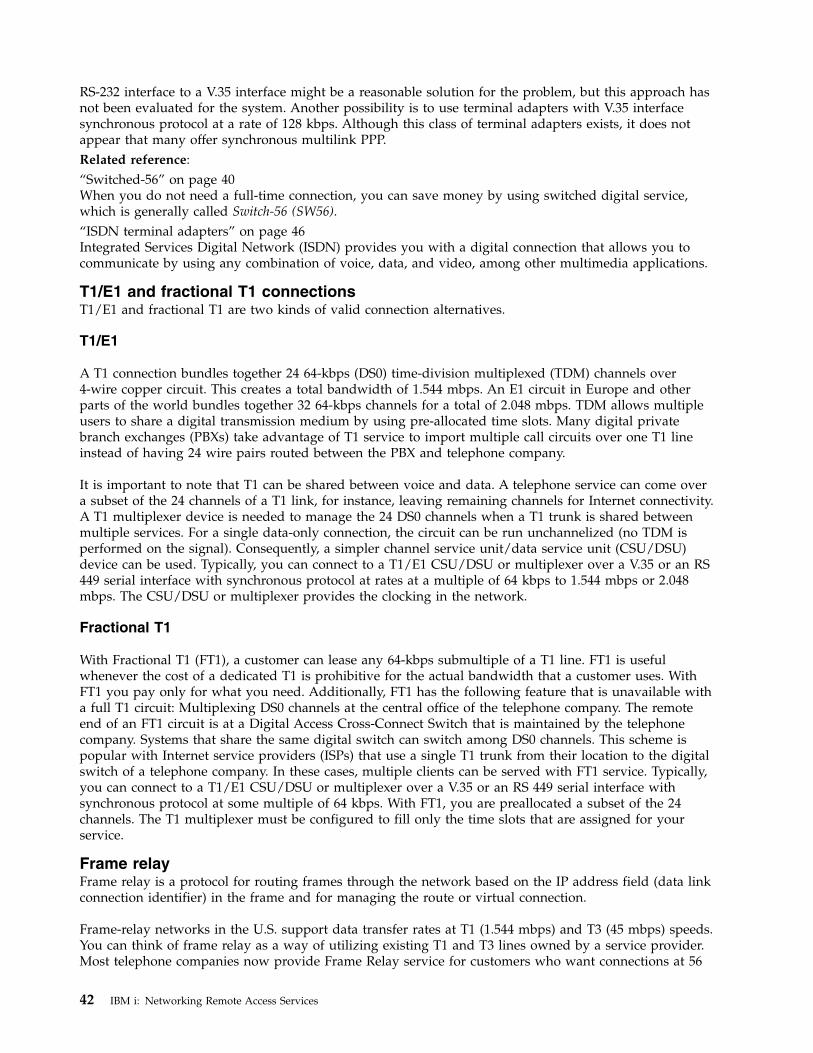
RS-232 interface to a V.35 interface might be a reasonable solution for the problem, but this approach hasnot been evaluated for the system. Another possibility is to use terminal adapters with V.35 interfacesynchronous protocol at a rate of 128 kbps. Although this class of terminal adapters exists, it does notappear that many offer synchronous multilink PPP.Related reference:“Switched-56” on page 40When you do not need a full-time connection, you can save money by using switched digital service,which is generally called Switch-56 (SW56).“ISDN terminal adapters” on page 46Integrated Services Digital Network (ISDN) provides you with a digital connection that allows you tocommunicate by using any combination of voice, data, and video, among other multimedia applications.
T1/E1 and fractional T1 connectionsT1/E1 and fractional T1 are two kinds of valid connection alternatives.
T1/E1
A T1 connection bundles together 24 64-kbps (DS0) time-division multiplexed (TDM) channels over4-wire copper circuit. This creates a total bandwidth of 1.544 mbps. An E1 circuit in Europe and otherparts of the world bundles together 32 64-kbps channels for a total of 2.048 mbps. TDM allows multipleusers to share a digital transmission medium by using pre-allocated time slots. Many digital privatebranch exchanges (PBXs) take advantage of T1 service to import multiple call circuits over one T1 lineinstead of having 24 wire pairs routed between the PBX and telephone company.
It is important to note that T1 can be shared between voice and data. A telephone service can come overa subset of the 24 channels of a T1 link, for instance, leaving remaining channels for Internet connectivity.A T1 multiplexer device is needed to manage the 24 DS0 channels when a T1 trunk is shared betweenmultiple services. For a single data-only connection, the circuit can be run unchannelized (no TDM isperformed on the signal). Consequently, a simpler channel service unit/data service unit (CSU/DSU)device can be used. Typically, you can connect to a T1/E1 CSU/DSU or multiplexer over a V.35 or an RS449 serial interface with synchronous protocol at rates at a multiple of 64 kbps to 1.544 mbps or 2.048mbps. The CSU/DSU or multiplexer provides the clocking in the network.
Fractional T1
With Fractional T1 (FT1), a customer can lease any 64-kbps submultiple of a T1 line. FT1 is usefulwhenever the cost of a dedicated T1 is prohibitive for the actual bandwidth that a customer uses. WithFT1 you pay only for what you need. Additionally, FT1 has the following feature that is unavailable witha full T1 circuit: Multiplexing DS0 channels at the central office of the telephone company. The remoteend of an FT1 circuit is at a Digital Access Cross-Connect Switch that is maintained by the telephonecompany. Systems that share the same digital switch can switch among DS0 channels. This scheme ispopular with Internet service providers (ISPs) that use a single T1 trunk from their location to the digitalswitch of a telephone company. In these cases, multiple clients can be served with FT1 service. Typically,you can connect to a T1/E1 CSU/DSU or multiplexer over a V.35 or an RS 449 serial interface withsynchronous protocol at some multiple of 64 kbps. With FT1, you are preallocated a subset of the 24channels. The T1 multiplexer must be configured to fill only the time slots that are assigned for yourservice.
Frame relayFrame relay is a protocol for routing frames through the network based on the IP address field (data linkconnection identifier) in the frame and for managing the route or virtual connection.
Frame-relay networks in the U.S. support data transfer rates at T1 (1.544 mbps) and T3 (45 mbps) speeds.You can think of frame relay as a way of utilizing existing T1 and T3 lines owned by a service provider.Most telephone companies now provide Frame Relay service for customers who want connections at 56
42 IBM i: Networking Remote Access Services
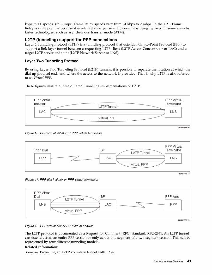
kbps to T1 speeds. (In Europe, Frame Relay speeds vary from 64 kbps to 2 mbps. In the U.S., FrameRelay is quite popular because it is relatively inexpensive. However, it is being replaced in some areas byfaster technologies, such as asynchronous transfer mode (ATM).
L2TP (tunneling) support for PPP connectionsLayer 2 Tunneling Protocol (L2TP) is a tunneling protocol that extends Point-to-Point Protocol (PPP) tosupport a link layer tunnel between a requesting L2TP client (L2TP Access Concentrator or LAC) and atarget L2TP server endpoint (L2TP Network Server or LNS).
Layer Two Tunneling Protocol
By using Layer Two Tunneling Protocol (L2TP) tunnels, it is possible to separate the location at which thedial-up protocol ends and where the access to the network is provided. That is why L2TP is also referredto as Virtual PPP.
These figures illustrate three different tunneling implementations of L2TP.
The L2TP protocol is documented as a Request for Comment (RFC) standard, RFC-2661. An L2TP tunnelcan extend across an entire PPP session or only across one segment of a two-segment session. This can berepresented by four different tunneling models.Related information:Scenario: Protecting an L2TP voluntary tunnel with IPSec
Figure 10. PPP virtual initiator or PPP virtual terminator
Figure 11. PPP dial initiator or PPP virtual terminator
Figure 12. PPP virtual dial or PPP virtual answer
Remote Access Services 43
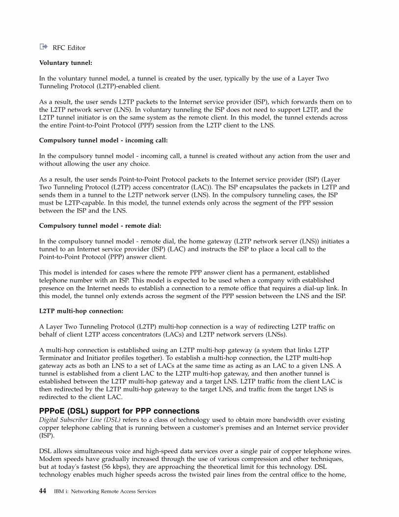
RFC Editor
Voluntary tunnel:
In the voluntary tunnel model, a tunnel is created by the user, typically by the use of a Layer TwoTunneling Protocol (L2TP)-enabled client.
As a result, the user sends L2TP packets to the Internet service provider (ISP), which forwards them on tothe L2TP network server (LNS). In voluntary tunneling the ISP does not need to support L2TP, and theL2TP tunnel initiator is on the same system as the remote client. In this model, the tunnel extends acrossthe entire Point-to-Point Protocol (PPP) session from the L2TP client to the LNS.
Compulsory tunnel model - incoming call:
In the compulsory tunnel model - incoming call, a tunnel is created without any action from the user andwithout allowing the user any choice.
As a result, the user sends Point-to-Point Protocol packets to the Internet service provider (ISP) (LayerTwo Tunneling Protocol (L2TP) access concentrator (LAC)). The ISP encapsulates the packets in L2TP andsends them in a tunnel to the L2TP network server (LNS). In the compulsory tunneling cases, the ISPmust be L2TP-capable. In this model, the tunnel extends only across the segment of the PPP sessionbetween the ISP and the LNS.
Compulsory tunnel model - remote dial:
In the compulsory tunnel model - remote dial, the home gateway (L2TP network server (LNS)) initiates atunnel to an Internet service provider (ISP) (LAC) and instructs the ISP to place a local call to thePoint-to-Point Protocol (PPP) answer client.
This model is intended for cases where the remote PPP answer client has a permanent, establishedtelephone number with an ISP. This model is expected to be used when a company with establishedpresence on the Internet needs to establish a connection to a remote office that requires a dial-up link. Inthis model, the tunnel only extends across the segment of the PPP session between the LNS and the ISP.
L2TP multi-hop connection:
A Layer Two Tunneling Protocol (L2TP) multi-hop connection is a way of redirecting L2TP traffic onbehalf of client L2TP access concentrators (LACs) and L2TP network servers (LNSs).
A multi-hop connection is established using an L2TP multi-hop gateway (a system that links L2TPTerminator and Initiator profiles together). To establish a multi-hop connection, the L2TP multi-hopgateway acts as both an LNS to a set of LACs at the same time as acting as an LAC to a given LNS. Atunnel is established from a client LAC to the L2TP multi-hop gateway, and then another tunnel isestablished between the L2TP multi-hop gateway and a target LNS. L2TP traffic from the client LAC isthen redirected by the L2TP multi-hop gateway to the target LNS, and traffic from the target LNS isredirected to the client LAC.
PPPoE (DSL) support for PPP connectionsDigital Subscriber Line (DSL) refers to a class of technology used to obtain more bandwidth over existingcopper telephone cabling that is running between a customer's premises and an Internet service provider(ISP).
DSL allows simultaneous voice and high-speed data services over a single pair of copper telephone wires.Modem speeds have gradually increased through the use of various compression and other techniques,but at today's fastest (56 kbps), they are approaching the theoretical limit for this technology. DSLtechnology enables much higher speeds across the twisted pair lines from the central office to the home,
44 IBM i: Networking Remote Access Services
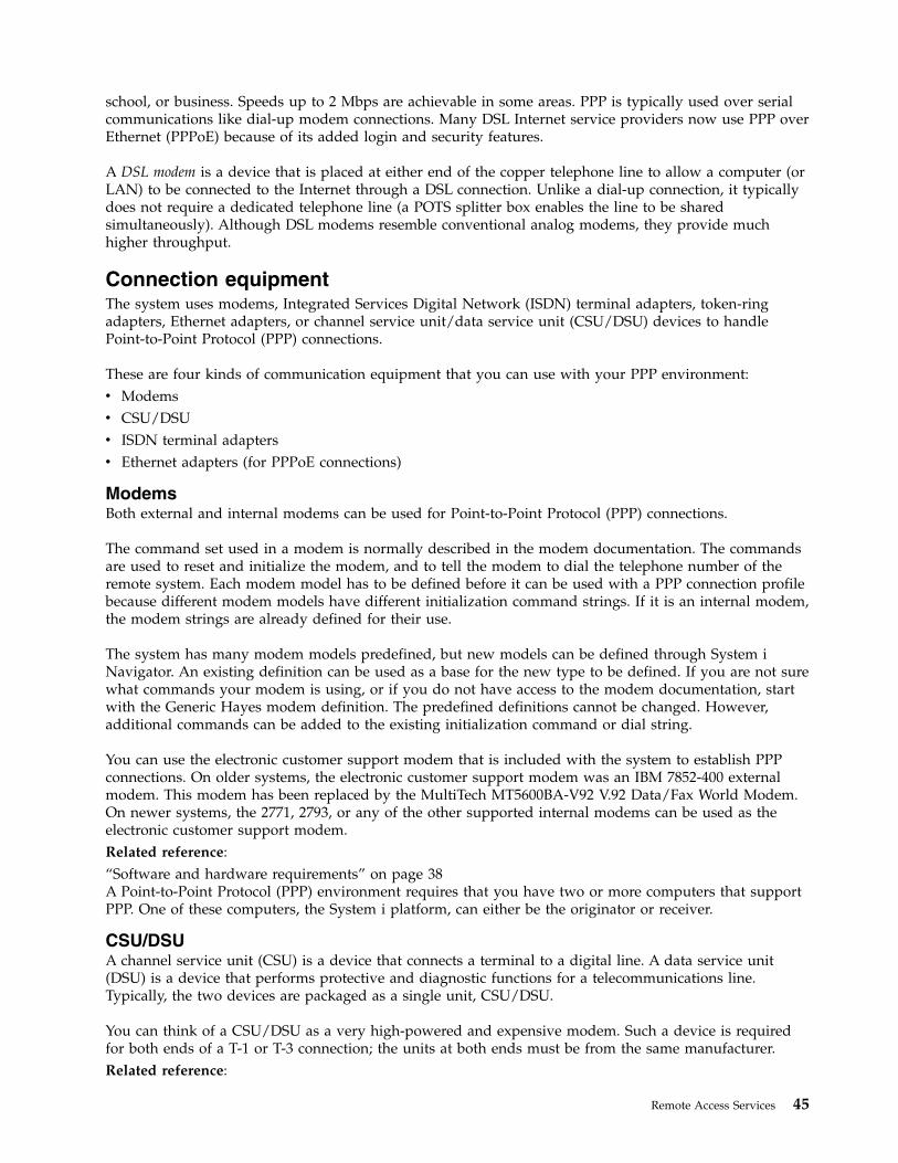
school, or business. Speeds up to 2 Mbps are achievable in some areas. PPP is typically used over serialcommunications like dial-up modem connections. Many DSL Internet service providers now use PPP overEthernet (PPPoE) because of its added login and security features.
A DSL modem is a device that is placed at either end of the copper telephone line to allow a computer (orLAN) to be connected to the Internet through a DSL connection. Unlike a dial-up connection, it typicallydoes not require a dedicated telephone line (a POTS splitter box enables the line to be sharedsimultaneously). Although DSL modems resemble conventional analog modems, they provide muchhigher throughput.
Connection equipmentThe system uses modems, Integrated Services Digital Network (ISDN) terminal adapters, token-ringadapters, Ethernet adapters, or channel service unit/data service unit (CSU/DSU) devices to handlePoint-to-Point Protocol (PPP) connections.
These are four kinds of communication equipment that you can use with your PPP environment:v Modemsv CSU/DSUv ISDN terminal adaptersv Ethernet adapters (for PPPoE connections)
ModemsBoth external and internal modems can be used for Point-to-Point Protocol (PPP) connections.
The command set used in a modem is normally described in the modem documentation. The commandsare used to reset and initialize the modem, and to tell the modem to dial the telephone number of theremote system. Each modem model has to be defined before it can be used with a PPP connection profilebecause different modem models have different initialization command strings. If it is an internal modem,the modem strings are already defined for their use.
The system has many modem models predefined, but new models can be defined through System iNavigator. An existing definition can be used as a base for the new type to be defined. If you are not surewhat commands your modem is using, or if you do not have access to the modem documentation, startwith the Generic Hayes modem definition. The predefined definitions cannot be changed. However,additional commands can be added to the existing initialization command or dial string.
You can use the electronic customer support modem that is included with the system to establish PPPconnections. On older systems, the electronic customer support modem was an IBM 7852-400 externalmodem. This modem has been replaced by the MultiTech MT5600BA-V92 V.92 Data/Fax World Modem.On newer systems, the 2771, 2793, or any of the other supported internal modems can be used as theelectronic customer support modem.Related reference:“Software and hardware requirements” on page 38A Point-to-Point Protocol (PPP) environment requires that you have two or more computers that supportPPP. One of these computers, the System i platform, can either be the originator or receiver.
CSU/DSUA channel service unit (CSU) is a device that connects a terminal to a digital line. A data service unit(DSU) is a device that performs protective and diagnostic functions for a telecommunications line.Typically, the two devices are packaged as a single unit, CSU/DSU.
You can think of a CSU/DSU as a very high-powered and expensive modem. Such a device is requiredfor both ends of a T-1 or T-3 connection; the units at both ends must be from the same manufacturer.Related reference:
Remote Access Services 45
“Software and hardware requirements” on page 38A Point-to-Point Protocol (PPP) environment requires that you have two or more computers that supportPPP. One of these computers, the System i platform, can either be the originator or receiver.“Digital service and Digital Data Services” on page 40You can use digital service and Digital Data Services (DDS) with Point-to-Point Protocol (PPP).
ISDN terminal adaptersIntegrated Services Digital Network (ISDN) provides you with a digital connection that allows you tocommunicate by using any combination of voice, data, and video, among other multimedia applications.
You need to verify that your terminal adapter is rated for use on the system.
Follow these steps to configure your terminal adapter:1. In System i Navigator, select your system and expand Network > Remote Access Services.2. Right-click Modems, and select New Modem.3. From the New Modem Properties dialog box, enter the correct values in all the field boxes of the
General tab. Ensure that you specify ISDN terminal adapter as the communications device.4. Select the ISDN Parameters tab.5. Add or change ISDN properties on the ISDN Parameters tab to match the properties required by
your terminal adapter.Related tasks:“Example: Configuring an ISDN terminal adapter” on page 64The example demonstrates how to configure an Integrated Services Digital Network (ISDN) terminaladapter.Related reference:“Software and hardware requirements” on page 38A Point-to-Point Protocol (PPP) environment requires that you have two or more computers that supportPPP. One of these computers, the System i platform, can either be the originator or receiver.“Integrated Services Digital Network” on page 41Integrated Services Digital Network (ISDN) provides switched end-to-end digital connectivity. ISDN cancarry both voice and data over the same connection.
ISDN terminal adapter suggestions:
There are several different terminal adapters that you can use.
The suggested external Integrated Services Digital Network (ISDN) terminal adapter, or ISDN modem, isthe 3Com/U.S. Robotics Courier I ISDN V.Everything. It supports V.34 analog modem connections, V.90(X2), V.92, and multilink PPP over ISDN in both origination and answer modes on the system. It alsoautomatically supports Challenge Handshake Authentication Protocol (CHAP) over the ISDN PPPconnection. The following ISDN terminal adapters are also available: Zyxel Omni.net Plus TA, ZyxelOmni.net LCD plus TA, and ADtran ISU 2x64 Dual Port.v Connections that originate from the system. CHAP challenges that originate from the receiving side
are answered by the Courier I terminal adapter, while negotiating Password Authentication Protocol(PAP) authentication with the system. PAP responses do not appear on the ISDN connection.
v Connections that the system answers. The Courier I requires CHAP authentication by the calling sideif the answer configuration causes the system to open authentication with a CHAP challenge. If thesystem opens authentication with PAP, the Courier I terminal adapter authenticates with PAP.
If you are using a pre-1999 Courier I modem, verify that the Courier I modem is connected to yoursystem by a V.35 cable to get the best performance from your ISDN connection. An RS-232 to V.35modem cable is supplied with the Courier I modem; however, older versions of this cable have thewrong gender V.35 connector. Contact 3Com/US Robotics Customer Support for a replacement.
46 IBM i: Networking Remote Access Services
Note: According to 3Com/US Robotics, the V.35 version of this terminal adapter is no longer from thirdparty suppliers, though some V.35 versions might still come from third-party suppliers. The RS-232version is still suggested at somewhat reduced performance on the system because RS-232connections are limited to 115.2 KB.
Be sure to set the V.35 line speed on the system to 230.4 kbps.
ISDN terminal adapter restrictions:
The terminal adapters in this topic have been evaluated. They are suggested only for the origination ofIntegrated Services Digital Network (ISDN) remote connections from the system.
3Com Impact IQ ISDN:
This terminal adapter is not suggested for the System i platform for the following reasons:v The terminal adapter does not support V.34 analog modem connections. However, it can support V.34
analog modem connections by using the external RJ-11 connection.v The terminal adapter does not currently support V.90 connections.v The terminal adapter might not be connected to the system at speeds greater than 115 200 bps.v The terminal adapter does not automatically support Challenge Handshake Authentication Protocol
(CHAP). If you set S84 to 0, CHAP authentication is performed.v The system is unable to determine when the connection ends when monitoring the Data Set Ready
signal from the terminal adapter. This causes a potential system security exposure.
Motorola BitSurfr Pro ISDN:
This terminal adapter is not suggested for the System i platform for the following reasons:v The terminal adapter does not support V.34 analog modem connections. However, it can support V.34
analog modem connections by using the external RJ-11 connection.v The terminal adapter does not currently support V.90 connections.v The terminal adapter might not be connected to the system at speeds greater than 115 200 bps.v The terminal adapter does not automatically support CHAP authentication. However, setting @M2=C
allows CHAP authentication to be performed.v The terminal adapter does not automatically permit answering both single-link and multilink PPP calls.
The remote origination terminal adapter must be set to the same protocol (single-link or multilink) asthe answering terminal adapter.
v The hardware flow control mechanism does not work well with this terminal adapter. This causesdegraded performance when the system is sending data on a multilink PPP connection.
IP address handlingPoint-to-Point Protocol (PPP) connections enable several different sets of options for managing IPaddresses depending on the type of connection profile.v DHCP can centrally manage IP address assignments for your network. Learn how to setup and
manage DHCP services for your network. Refer to Dynamic Host Configuration Protocolv DNS can help you manage host names and their associated IP addresses. Learn how to setup and
manage DNS services for your network. Refer to Domain Name Systemv BOOTP is used to associate client workstations with your system, and assign them IP addresses. Learn
how to setup and manage BOOTP services for your network. Refer to Bootstrap ProtocolRelated reference:“Scenario: Connecting your system to a PPPoE access concentrator” on page 16Many Internet service providers (ISPs) provide high-speed Internet access over a Digital Subscriber Line(DSL) using Point-to-Point Protocol over Ethernet (PPPoE). You can connect your system to these ISPs to
Remote Access Services 47
provide high-bandwidth connections that preserve the benefits of Point-to-Point Protocol (PPP).
IP packet filteringIP packet filtering limits the services to individual users when they log on to a network.
Packet filtering can permit or deny access based on destination IP addresses or ports or both. Differentpolicies are enforced by defining multiple sets of packet filter rules with each having their own uniquePPP filter identifier. Packet filter rules can be assigned for a particular receiver connection profile or canbe assigned by using a Group Policy that will apply the filter rules for that category of user. The packetfilter rules themselves are not defined in PPP, but are defined under IP Packet Rules in System iNavigator.
For L2TP connections, VPN with IPSec filtering should be used to protect network traffic.Related reference:“Scenario: Connecting your system to a PPPoE access concentrator” on page 16Many Internet service providers (ISPs) provide high-speed Internet access over a Digital Subscriber Line(DSL) using Point-to-Point Protocol over Ethernet (PPPoE). You can connect your system to these ISPs toprovide high-bandwidth connections that preserve the benefits of Point-to-Point Protocol (PPP).Related information:IP filtering and network address translationVirtual Private Networking (VPN)
IP address management strategyBefore configuring a PPP connection profile, you should be familiar with your network IP addressmanagement strategy. This strategy influences many of the decisions throughout the configurationprocess including your authentication strategies, security considerations, and TCP/IP settings.
Starting in IBM i 7.1, PPP can support both IPv4 and IPv6 addresses. A PPP connection profile can haveonly IPv4 enabled, only IPv6 enabled, or both IPv4 and IPv6 enabled. By default, both IPv4 and IPv6 areenabled for a PPP connection profile.
Note: Establishing a physical PPP connection (e.g. dialing or answering) and LCP negotiation andauthentication are identical for both IPv4 and IPv6.
IPv4 Address Management
The IP Control Protocol (IPCP) is used to configure and enable IPv4 on both ends of a PPP link. Optionsrelated to IPCP and IPv4 address assignment are located on the TCP/IP IPv4 Settings section of aconnection profile.
Originator connection profiles
Typically, the local and remote IPv4 addresses defined for an originator profile will be defined as Assignedby remote system. This enables the administrators on the remote system to have control over the IPaddresses that will be used for the connection. Most all connections to Internet service providers (ISP)will be defined this way, although many ISPs can offer fixed IP addresses for an additional fee.
If you define fixed IP addresses for either the local or remote IP address, you must be sure that theremote system is defined to accept the IP addresses you have defined. One typical application is to defineyour local IP address as a fixed IP address and the remote to be assigned by the remote system. Thesystem you are connecting can be defined the same way so when you connect, the two systems willexchange IP addresses with each other as a way to learn the IP address of the remote system. This mightbe useful for one office calling another office for temporary connectivity.
48 IBM i: Networking Remote Access Services
|||
||
|
|||
||||
Another consideration is whether you want to enable IP address masquerading. For example, if thesystem connects to the Internet through an ISP, this can allow an attached network behind the system toaccess the Internet. Basically, the system hides the IP addresses of the systems on the network behind thelocal IP address assigned by the ISP, thus making all IP traffic appear to be from the system. There arealso additional routing considerations for both the systems on the LAN (to ensure their Internet traffic issent to the system) as well as the system where you need to enable the add remote system as the defaultroute box.
Receiver connection profiles
Receiver connection profiles have many more IPv4 address considerations and options than theOriginator Connection Profile does. How you configure the IP addresses depends on the IP addressmanagement plan for your network, your specific performance and functional requirements for thisconnection, and the security plan.
Local IP addresses
For a single receiver profile, you can define a unique IP address or use an existing local IP address onyour system to identify the end of the PPP connection. For receiver profiles defined to support multipleconnections at the same time, you must use an existing local IP address. If no existing local IP addressesare present, you can create a virtual IP address for this purpose.
Remote IP addresses
There are many options for assigning remote IP addresses to PPP clients. The following options can bespecified on the TCP/IP page of the receiver connection profile.
Note: If you want the remote system to be considered part of the LAN, you should configure IP addressrouting, specify an IP address within the IP address range for LAN-attached systems, and verifythat IP forwarding has been enabled for both this connection profile and the system.
Table 8. IPv4 address assignment options for receiver profile connections
Option Description
Fixed IP address You define the single IP address that is to be given to remote users when they dialin. This is a host only IP address (Subnet mask is 255.255.255.255) and is only forsingle connection receiver profiles.
Address Pool You define the starting IP address and then a range of how many additional IPaddresses to define. Each user that connects will then be given a unique IP addresswithin the defined range. This is a host only IP address (Subnet mask is255.255.255.255) and is only for multiple connection receiver profiles.
RADIUS The remote IP address and it's subnet mask will be determined by the Radius server.This is only if the following is defined:
v Radius support for authentication and IP addressing has been enabled from theRemote Access Server services configuration.
v Authentication is enabled for the receiver connection profile and is defined to beauthenticated remotely by Radius.
DHCP The remote IP address is determined by the DHCP server directly or indirectlythrough DHCP relay. This is only if DHCP support has been enabled from theRemote Access Server services configuration. This is a host only IP address (Subnetmask is 255.255.255.255).
Remote Access Services 49
||||
||
||
||||
|||||
|||
||
||
|||||
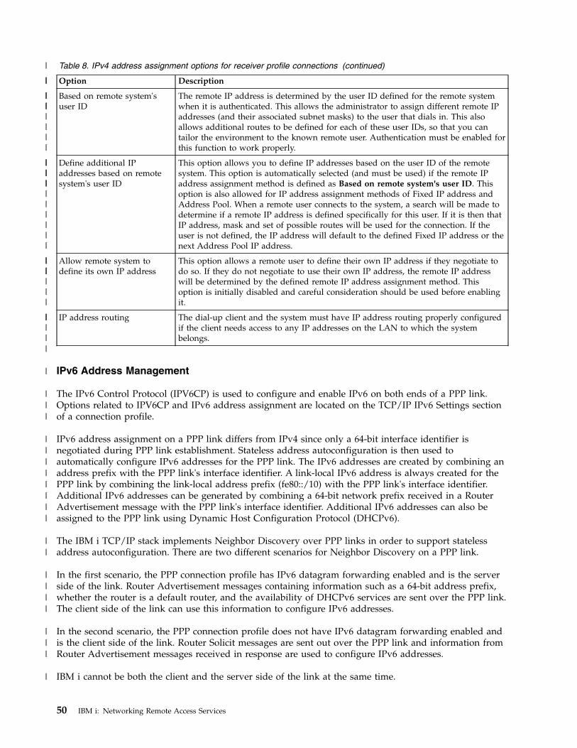
Table 8. IPv4 address assignment options for receiver profile connections (continued)
Option Description
Based on remote system'suser ID
The remote IP address is determined by the user ID defined for the remote systemwhen it is authenticated. This allows the administrator to assign different remote IPaddresses (and their associated subnet masks) to the user that dials in. This alsoallows additional routes to be defined for each of these user IDs, so that you cantailor the environment to the known remote user. Authentication must be enabled forthis function to work properly.
Define additional IPaddresses based on remotesystem's user ID
This option allows you to define IP addresses based on the user ID of the remotesystem. This option is automatically selected (and must be used) if the remote IPaddress assignment method is defined as Based on remote system's user ID. Thisoption is also allowed for IP address assignment methods of Fixed IP address andAddress Pool. When a remote user connects to the system, a search will be made todetermine if a remote IP address is defined specifically for this user. If it is then thatIP address, mask and set of possible routes will be used for the connection. If theuser is not defined, the IP address will default to the defined Fixed IP address or thenext Address Pool IP address.
Allow remote system todefine its own IP address
This option allows a remote user to define their own IP address if they negotiate todo so. If they do not negotiate to use their own IP address, the remote IP addresswill be determined by the defined remote IP address assignment method. Thisoption is initially disabled and careful consideration should be used before enablingit.
IP address routing The dial-up client and the system must have IP address routing properly configuredif the client needs access to any IP addresses on the LAN to which the systembelongs.
IPv6 Address Management
The IPv6 Control Protocol (IPV6CP) is used to configure and enable IPv6 on both ends of a PPP link.Options related to IPV6CP and IPv6 address assignment are located on the TCP/IP IPv6 Settings sectionof a connection profile.
IPv6 address assignment on a PPP link differs from IPv4 since only a 64-bit interface identifier isnegotiated during PPP link establishment. Stateless address autoconfiguration is then used toautomatically configure IPv6 addresses for the PPP link. The IPv6 addresses are created by combining anaddress prefix with the PPP link's interface identifier. A link-local IPv6 address is always created for thePPP link by combining the link-local address prefix (fe80::/10) with the PPP link's interface identifier.Additional IPv6 addresses can be generated by combining a 64-bit network prefix received in a RouterAdvertisement message with the PPP link's interface identifier. Additional IPv6 addresses can also beassigned to the PPP link using Dynamic Host Configuration Protocol (DHCPv6).
The IBM i TCP/IP stack implements Neighbor Discovery over PPP links in order to support statelessaddress autoconfiguration. There are two different scenarios for Neighbor Discovery on a PPP link.
In the first scenario, the PPP connection profile has IPv6 datagram forwarding enabled and is the serverside of the link. Router Advertisement messages containing information such as a 64-bit address prefix,whether the router is a default router, and the availability of DHCPv6 services are sent over the PPP link.The client side of the link can use this information to configure IPv6 addresses.
In the second scenario, the PPP connection profile does not have IPv6 datagram forwarding enabled andis the client side of the link. Router Solicit messages are sent out over the PPP link and information fromRouter Advertisement messages received in response are used to configure IPv6 addresses.
IBM i cannot be both the client and the server side of the link at the same time.
50 IBM i: Networking Remote Access Services
|
||
||||||||
|||
|||||||||
|||||||
|||||
|
|||
||||||||
||
||||
|||
|
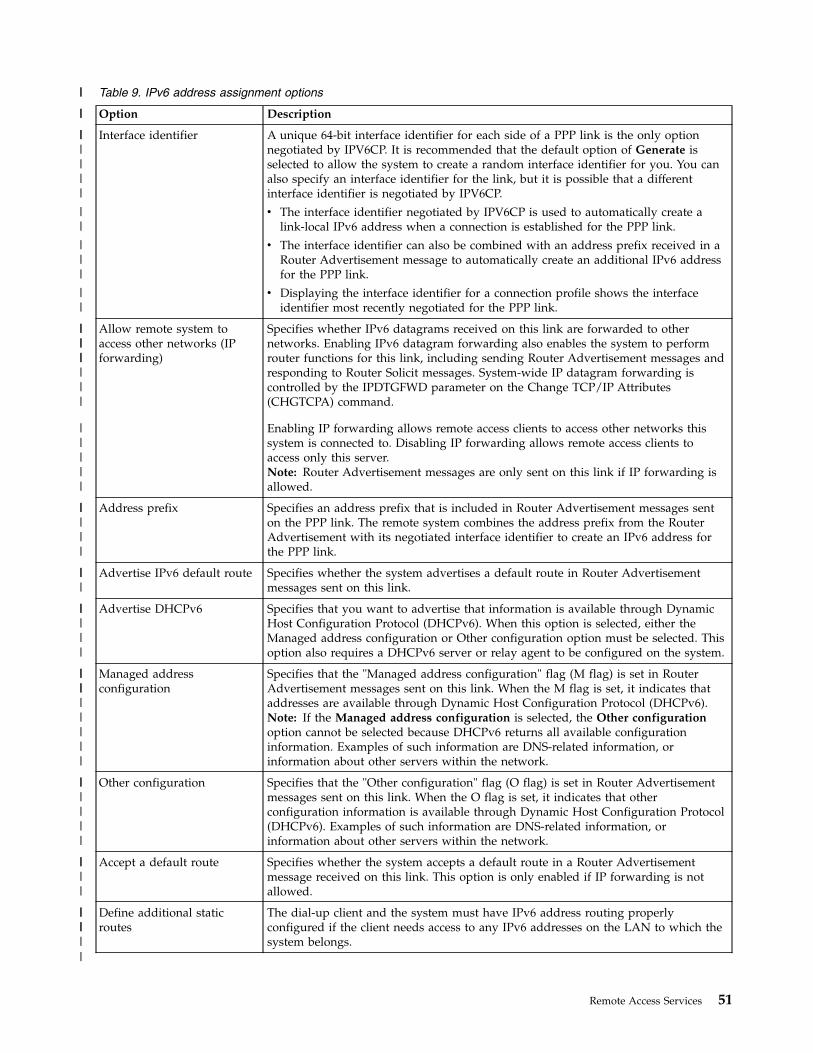
Table 9. IPv6 address assignment options
Option Description
Interface identifier A unique 64-bit interface identifier for each side of a PPP link is the only optionnegotiated by IPV6CP. It is recommended that the default option of Generate isselected to allow the system to create a random interface identifier for you. You canalso specify an interface identifier for the link, but it is possible that a differentinterface identifier is negotiated by IPV6CP.
v The interface identifier negotiated by IPV6CP is used to automatically create alink-local IPv6 address when a connection is established for the PPP link.
v The interface identifier can also be combined with an address prefix received in aRouter Advertisement message to automatically create an additional IPv6 addressfor the PPP link.
v Displaying the interface identifier for a connection profile shows the interfaceidentifier most recently negotiated for the PPP link.
Allow remote system toaccess other networks (IPforwarding)
Specifies whether IPv6 datagrams received on this link are forwarded to othernetworks. Enabling IPv6 datagram forwarding also enables the system to performrouter functions for this link, including sending Router Advertisement messages andresponding to Router Solicit messages. System-wide IP datagram forwarding iscontrolled by the IPDTGFWD parameter on the Change TCP/IP Attributes(CHGTCPA) command.
Enabling IP forwarding allows remote access clients to access other networks thissystem is connected to. Disabling IP forwarding allows remote access clients toaccess only this server.Note: Router Advertisement messages are only sent on this link if IP forwarding isallowed.
Address prefix Specifies an address prefix that is included in Router Advertisement messages senton the PPP link. The remote system combines the address prefix from the RouterAdvertisement with its negotiated interface identifier to create an IPv6 address forthe PPP link.
Advertise IPv6 default route Specifies whether the system advertises a default route in Router Advertisementmessages sent on this link.
Advertise DHCPv6 Specifies that you want to advertise that information is available through DynamicHost Configuration Protocol (DHCPv6). When this option is selected, either theManaged address configuration or Other configuration option must be selected. Thisoption also requires a DHCPv6 server or relay agent to be configured on the system.
Managed addressconfiguration
Specifies that the "Managed address configuration" flag (M flag) is set in RouterAdvertisement messages sent on this link. When the M flag is set, it indicates thataddresses are available through Dynamic Host Configuration Protocol (DHCPv6).Note: If the Managed address configuration is selected, the Other configurationoption cannot be selected because DHCPv6 returns all available configurationinformation. Examples of such information are DNS-related information, orinformation about other servers within the network.
Other configuration Specifies that the "Other configuration" flag (O flag) is set in Router Advertisementmessages sent on this link. When the O flag is set, it indicates that otherconfiguration information is available through Dynamic Host Configuration Protocol(DHCPv6). Examples of such information are DNS-related information, orinformation about other servers within the network.
Accept a default route Specifies whether the system accepts a default route in a Router Advertisementmessage received on this link. This option is only enabled if IP forwarding is notallowed.
Define additional staticroutes
The dial-up client and the system must have IPv6 address routing properlyconfigured if the client needs access to any IPv6 addresses on the LAN to which thesystem belongs.
Remote Access Services 51
||
||
||||||
||
|||
||
|||
||||||
|||||
|||||
|||
|||||
|||||||||
||||||
||||
||||||
Related information:IPv6 concepts
System authenticationPPP connections with a System i platform support several options for authenticating both remote clientsdialing in to the system and connections to an ISP or another system that the system is dialing to.
The system supports several methods for maintaining authentication information. These methods includesimple validation lists on the system that contain lists of authorized users and their passwords to supportfor Remote Authentication Dial In User Service (RADIUS) servers. RADIUS servers maintain detailedinformation for network users. The system also supports several options for encrypting user ID andpassword information, ranging from a simple password exchange to support with Challenge HandshakeAuthentication Protocol (CHAP-MD5). You can specify your preferences for system authentication,including a user ID and password to validate the system when dialing out, on the Authentication tab ofthe connection profile in System i Navigator.Related reference:“Scenario: Connecting your system to a PPPoE access concentrator” on page 16Many Internet service providers (ISPs) provide high-speed Internet access over a Digital Subscriber Line(DSL) using Point-to-Point Protocol over Ethernet (PPPoE). You can connect your system to these ISPs toprovide high-bandwidth connections that preserve the benefits of Point-to-Point Protocol (PPP).“Scenario: Authenticating dial-up connections with RADIUS NAS” on page 28A Network Access Server (NAS) running on the system can route authentication requests from dial-inclients to a separate Remote Authentication Dial In User Service (RADIUS) server. If authenticated,RADIUS can also control the IP addresses assigned to the user. “Scenario: Managing remote user access to resources using group policies and IP filtering” on page 30Group access policies identify distinct user groups for a connection, and allow you to apply commonconnection attributes and security settings to the entire group. You can use group policies, along with IPfiltering, to permit and restrict access to specific IP addresses on your network.
Challenge Handshake Authentication Protocol with MD5Challenge Handshake Authentication Protocol (CHAP-MD5) uses an algorithm (MD-5) to calculate avalue that is known only to the authenticating system and the remote device.
With CHAP, the user ID and the password are always encrypted, so it is a more secure protocol thanPassword Authentication Protocol (PAP). This protocol is effective against playback and trial-and-erroraccess attempts. CHAP authentication can occur more than once during a connection.
The authenticating system sends a challenge to the remote device that is attempting to connect to thenetwork. The remote device responds with a value that is calculated by a common algorithm (MD-5) thatboth devices use. The authenticating system checks the response against its own calculation.Authentication is acknowledged when the values match; otherwise, the connection is ended.Related reference:“Scenario: Connecting remote dial-in clients to your system” on page 19Remote users, such as telecommuters or mobile clients, often require access to a company's network.These dial-in clients can gain access to a system with Point-to-Point Protocol (PPP).“Password Authentication Protocol” on page 53Password Authentication Protocol (PAP) uses a two-way handshake to provide the peer system with asimple method to establish its identity.
Extensible Authentication ProtocolExtensible Authentication Protocol (EAP) enables third-party authentication modules to interact with thePPP implementation.
52 IBM i: Networking Remote Access Services
|
EAP extends PPP by providing a standard support mechanism for authentication schemes such as token(smart) cards, Kerberos, Public Key, and S/Key. EAP responds to the increasing demand to augmentauthentication with third-party security devices. EAP protects secure virtual private networks (VPN) fromhackers that use dictionary attacks and password guessing. EAP improves on Password AuthenticationProtocol (PAP) and Challenge Handshake Authentication Protocol (CHAP).
With EAP, the authentication information is not included in the information, but rather with theinformation. This allows remote systems to negotiate the necessary authentication before receiving orpassing on any information.
The system does not directly support EAP. You can, however, use remote authentication with a RemoteAuthentication Dial In User Service (RADIUS) server that might support some of the additionalauthentication schemes described previously.
Password Authentication ProtocolPassword Authentication Protocol (PAP) uses a two-way handshake to provide the peer system with asimple method to establish its identity.
The handshake is conducted when establishing a link. After the link is established, the remote devicesends a user ID and password pair to the authenticating system. Depending on the correctness of thepair, the authenticating system either continues or ends the connection.
PAP authentication requires the user name and password to be sent to the remote system in clear textform. With PAP, the user ID and password are never encrypted, which makes them possible to trace andvulnerable to hacker attack. For this reason, you should use Challenge Handshake AuthenticationProtocol (CHAP) whenever possible.Related reference:“Challenge Handshake Authentication Protocol with MD5” on page 52Challenge Handshake Authentication Protocol (CHAP-MD5) uses an algorithm (MD-5) to calculate avalue that is known only to the authenticating system and the remote device.
Remote Authentication Dial In User Service overviewRemote Authentication Dial In User Service (RADIUS) is an Internet standard protocol that providescentralized authentication, accounting and IP management services for remote access users in adistributed dial-up network.
The RADIUS client-server model has a Network Access Server (NAS) operating as a client to a RADIUSserver. The system, acting as the NAS, sends user and connection information to a designated RADIUSserver using the RADIUS standard protocol defined in RFC 2865.
RADIUS servers act on received user connection requests by authenticating the user and then return allconfiguration information necessary to the NAS, so that the NAS (the system) can deliver authorizedservices to the authenticated dial-in user.
If a RADIUS server cannot be reached, the system can route authentication requests to an alternate server.This enables global enterprises to offer their users a dial-in service with a unique login user ID forcorporate-wide access, no matter what access point is being used.
When an authentication request is received by the RADIUS server, the request is validated; then theRADIUS server decrypts the data packet to access the user name and password information. Theinformation is passed onto the appropriate security system that is supported. This might be UNIXpassword files, Kerberos, a commercial security system, or even a custom-developed security system. TheRADIUS server sends back to the system any services that the authenticated user is authorized to use,such as an IP address. RADIUS accounting requests are handled in a similar manner. Remote user'saccounting information can be sent to a designated RADIUS accounting server. The RADIUS accounting
Remote Access Services 53
standard protocol is defined in RFC 2866. The RADIUS accounting server acts on received accountingrequests by logging the information from the RADIUS accounting request.Related reference:“Scenario: Authenticating dial-up connections with RADIUS NAS” on page 28A Network Access Server (NAS) running on the system can route authentication requests from dial-inclients to a separate Remote Authentication Dial In User Service (RADIUS) server. If authenticated,RADIUS can also control the IP addresses assigned to the user.
Validation listA validation list is used to store user ID and password information about remote users.
You can use existing validation lists or create your own from the Receiver Connection Profileauthentication page. Validation list entries also require you to identify an authentication protocol type toassociate with the user ID and password. This might be encrypted - CHAP-MD5/EAP or unencrypted -PAP.
See the online help for more information.Related reference:“Scenario: Managing remote user access to resources using group policies and IP filtering” on page 30Group access policies identify distinct user groups for a connection, and allow you to apply commonconnection attributes and security settings to the entire group. You can use group policies, along with IPfiltering, to permit and restrict access to specific IP addresses on your network.
Bandwidth considerations for multilinkAdditional bandwidth is often required to complete certain tasks, but it is not always required.
The purchase of specialized hardware and expensive communication lines might not be justified. The PPPMultilink Protocol (MP) groups multiple PPP links together to form a single virtual link or bundle. Theaggregation of multiple links increases the total effective bandwidth between two systems by usingstandard modems and telephone lines. You can include up to six links in an MP bundle. To establish amultilink connection, both ends of the PPP link must support the multilink protocol. The multilinkprotocol is documented as a Request for Comment (RFC) standard RFC-1990.
Bandwidth On Demand
The ability to dynamically add and remove physical links allows a system to be configured to supplybandwidth only when it is needed. This approach is commonly referred to as Bandwidth on Demand andallows you to only pay for the additional bandwidth when you actually use it. To realize the benefits ofBandwidth on Demand, at least one peer must be capable of monitoring utilization of the totalbandwidth currently in an MP bundle. Links can be added to or removed from the bundle whenbandwidth utilization exceeds values defined by configuration. The Bandwidth Allocation Protocol allowspeers to negotiate adding and removing links in an MP bundle. RFC-2125 documents both the PPPBandwidth Allocation Protocol (BAP) and Bandwidth Allocation Control Protocol (BACP).Related information:
RFC Editor
Configuring PPPBefore you can use PPP to set up a point-to-point connection, you must configure your PPP environment.Related reference:“Related information for Remote Access Services” on page 73IBM Redbooks publications and Web sites contain information that relates to the Remote Access Servicestopic collection. You can view or print any of the PDF files.
54 IBM i: Networking Remote Access Services
Creating a connection profileThe first step in configuring a PPP connection between systems is to create a connection profile on thesystem.
The connection profile is the logical representation of the following connection details:v Line and profile typev Multilink settingsv Remote telephone numbers and dialing optionsv Authenticationv TCP/IP settings: IP addresses and routingv Work management and connection customizationv Domain name servers
Remote Access Services, under the Network directory, contains the following objects:v Originator connection profilesv Receiver connection profilesv Modems
Follow these steps to create a connection profile:1. In System i Navigator, select your system and expand Network > Remote Access Services.2. Select one from the following options:v Right-click Originator Connection Profiles to set the system to initiate.v Right-click Receiver Connection Profiles to set the system to allow incoming connections from
remote systems and users.3. Select New Profile.4. On the New Point-to-Point Connection Profile Setup page, select the protocol type.5. Specify the mode selections.6. Select the link configuration.7. Click OK.
The New Point-to-Point Profile Properties page appears. You can set the rest of the values that arespecific to your network. See the online help for specific information.
Related tasks:“Associating a modem with a line description” on page 65The topic demonstrates the steps for associating a modem with a line description.Related reference:“Scenario: Connecting your system to a PPPoE access concentrator” on page 16Many Internet service providers (ISPs) provide high-speed Internet access over a Digital Subscriber Line(DSL) using Point-to-Point Protocol over Ethernet (PPPoE). You can connect your system to these ISPs toprovide high-bandwidth connections that preserve the benefits of Point-to-Point Protocol (PPP).“Scenario: Connecting remote dial-in clients to your system” on page 19Remote users, such as telecommuters or mobile clients, often require access to a company's network.These dial-in clients can gain access to a system with Point-to-Point Protocol (PPP).“Scenario: Connecting your office LAN to the Internet with a modem” on page 21Administrators typically set up office networks for employees to access the Internet. Administrators canuse a modem to connect the system to an Internet service provider (ISP). LAN-attached PC clients cancommunicate with the Internet using the IBM i operating system as a gateway.“Scenario: Connecting your corporate and remote networks with a modem” on page 24A modem enables two remote locations (such as a central office and a branch office) to exchange databetween them. Point-to-Point Protocol (PPP) can connect two LANs together by establishing a connection
Remote Access Services 55

between a system in the central office and another one in the branch office.“Scenario: Managing remote user access to resources using group policies and IP filtering” on page 30Group access policies identify distinct user groups for a connection, and allow you to apply commonconnection attributes and security settings to the entire group. You can use group policies, along with IPfiltering, to permit and restrict access to specific IP addresses on your network.
Protocol type: PPP or Serial Line Internet Protocol (SLIP)PPP replaces Serial Line Internet Protocol (SLIP) as the protocol of choice for point-to-point connections.
PPP enables interoperability among the remote access software of different manufacturers. PPP alsoenables multiple network communication protocols to use the same physical communication line.
The SLIP Request for Comment (RFC) never becomes an Internet standard because of the followingdeficiencies:v SLIP has no standard way to define IP addressing between the two hosts. This means that an
unnumbered net cannot be used.v SLIP has no support for error detection or error compression. Error detection or error compression is
implemented in PPP.v SLIP has no support for system authentication, while PPP has two-way authentication.
SLIP is still used today, and it is supported on the IBM i operating system. However, IBM suggests thatyou use PPP when setting up point-to-point connectivity. SLIP provides no support for multilinkconnections. Compared to SLIP, PPP has better authentication. PPP performs better because of itscompression facilities.
Note: SLIP connection profiles that are defined with ASYNC line types are no longer supported in thisrelease. If you have these connection profiles, you must migrate them to either a SLIP profile or aPPP profile that uses a PPP line type.
Mode selectionsThe mode selections for a Point-to-Point Protocol (PPP) connection profile include selections for theconnection type and the operating mode. Your mode selections specify how your system uses the newPPP connection.
Follow these steps to specify your mode selections:1. Select one of the following connection types:v Switched linev Leased linev Layer Two Tunneling Protocol (L2TP) (virtual line)v Point-to-Point Protocol over Ethernet (PPPoE) line
2. Select the operating mode that is appropriate for the new PPP connection.3. Record the connection type and operating mode that you selected. You need this information when
you start to configure your PPP connections.
Switched line:
When you use a modem (internal or external) or an external Integrated Services Digital Network (ISDN)terminal adapter to connect over a telephone line, select the switched line connection.
The switched line connection type has the following operating modes:
Answer
Choose this operating mode to enable a remote system to dial into the system.
56 IBM i: Networking Remote Access Services
Dial
Choose this operating mode to enable the system to dial out to a remote system.
Dial on-demand (dial only)
Choose this operating mode to enable the system to automatically dial out to a remote systemwhen TCP/IP traffic for the remote system is detected on the system. The connection ends whenthe data transmission is complete, and no TCP/IP traffic occurs for a specific period of time.
Dial on-demand (answer-enabled dedicated peer)
Choose this operating mode to enable the system to answer calls from a dedicated remote system.This operating mode also allows the system to call the remote system when TCP/IP traffic for theremote system is detected. If both systems use IBM i operating system and use this operatingmode, TCP/IP traffic flows between the two systems on demand and without the need for apermanent physical connection. This operating mode requires a dedicated resource. The remotepeer must dial in for the operating mode to function properly.
Dial on-demand (remote peer enabled)
Choose this operating mode to enable a remote system to be dialed or answered. To handleincoming calls, you must reference an existing answer profile from a Point-to-Point Protocol (PPP)connection profile that specifies this operating mode. This enables one answer profile to handleall incoming calls from one or more remote peers and a separate dial on-demand profile for eachoutgoing call. This operating mode does not require a dedicated resource to handle the incomingcalls from remote peers.
Leased line:
If you have a dedicated line between the local system and the remote system, select the leased lineconnection. If you have a leased line, you do not need a modem or an Integrated Services DigitalNetwork (ISDN) terminal adapter to connect the two systems.
A leased line connection between two systems is considered a permanent or dedicated line. It is alwaysopen. One end of the leased line connection is configured as the initiator, and the other end is configuredas the terminator.
The leased line connection type has the following operating modes:
Terminator
Choose this operating mode to enable a remote system to access the system through a dedicatedline. This operating mode refers to a leased line answer profile.
Initiator
Choose this operating mode to enable the system to access a remote system through a dedicatedline. This operating mode refers to a leased line dial profile.
L2TP (virtual line):
If you want to provide a connection between systems that use Layer Two Tunneling Protocol (L2TP),select the L2TP connection.
After an L2TP tunnel is established, a virtual Point-to-Point Protocol (PPP) connection is made betweenyour system and the remote system. By using L2TP tunneling in conjunction with IP security (IP-SEC),you can send, route, and receive secure data over the Internet.
The L2TP (virtual line) connection type has the following operating modes:
Terminator
Remote Access Services 57
Choose this operating mode to enable a remote system to connect to the system over an L2TPtunnel.
Initiator
Choose this operating mode to enable the system to connect to a remote system over an L2TPtunnel.
Remote dial
Choose this operating mode to enable the system to connect to another system or an Internetservice provider (ISP) over an L2TP tunnel, and to direct the ISP to dial a remote PPP client.
Multi-hop initiator
Choose this operating mode to enable the system to establish a multi-hop connection.
Note: The L2TP Terminator profile that this multi-hop initiator is associated with needs to havethe Allow multi-hop connection box checked and have a PPP validation list entry thatlinks the PPP user name to the multi-hop initiator profile.
PPPoE line:
Point-to-Point Protocol over Ethernet (PPPoE) connections use a virtual line to send PPP data (through anEthernet adapter) to a Digital Subscriber Line (DSL) modem that is provided by your Internet serviceprovider (ISP). The modem is also connected to the Ethernet-based LAN.
This enables high-speed Internet access for LAN users through PPP sessions on the IBM i operatingsystem. After the connection between the system and the ISP has started, individual users on the LANcan start unique sessions with the ISP over PPPoE.
PPPoE connections are only used by originator connection profiles. The connections imply an Initiatoroperating mode and use only a single line.
Link configurationLink configuration defines the type of line service that your Point-to-Point Protocol (PPP) connectionprofile uses to establish a connection.
The types of line service depend on the connection type that you specify.Related reference:“Scenario: Connecting your system to a PPPoE access concentrator” on page 16Many Internet service providers (ISPs) provide high-speed Internet access over a Digital Subscriber Line(DSL) using Point-to-Point Protocol over Ethernet (PPPoE). You can connect your system to these ISPs toprovide high-bandwidth connections that preserve the benefits of Point-to-Point Protocol (PPP).“Scenario: Connecting remote dial-in clients to your system” on page 19Remote users, such as telecommuters or mobile clients, often require access to a company's network.These dial-in clients can gain access to a system with Point-to-Point Protocol (PPP).“Scenario: Connecting your office LAN to the Internet with a modem” on page 21Administrators typically set up office networks for employees to access the Internet. Administrators canuse a modem to connect the system to an Internet service provider (ISP). LAN-attached PC clients cancommunicate with the Internet using the IBM i operating system as a gateway.“Scenario: Connecting your corporate and remote networks with a modem” on page 24A modem enables two remote locations (such as a central office and a branch office) to exchange databetween them. Point-to-Point Protocol (PPP) can connect two LANs together by establishing a connectionbetween a system in the central office and another one in the branch office.
58 IBM i: Networking Remote Access Services
Single line:
To define a Point-to-Point Protocol (PPP) line that is associated with an analog modem, select this lineservice. This option is also used for leased lines where a modem is not required. The PPP connectionprofile always uses the same IBM i communications port resource.
An analog single line, if required, might be configured as shared between an answer profile and a dialprofile. The dynamic resource sharing is a new function designed to enhance resource usability. UntilV5R2, the modem resources were committed as soon as the profile using it was started. This was limitingthe user to one resource per session, even if the resource was in the passive wait state. Now, new sharingrules apply when a specific resource has been accessed. There are two cases: first, a dial profile wasstarted before an answer profile; second, an answer profile was started before a dial profile. Theassumption is that the resource sharing is enabled. In the first case, the dial profile that was started willsuccessfully connect. The answer profile that was started second, will wait for the line to becomeavailable. After the dial connection was ended, the answer profile will request the line, and will start. Inthe second case, the answer profile that was started will wait for the incoming connections. Unless anincoming connection was made, the dial profile that was started second, will "borrow" the line from theanswer profile, which will "lend" the line. The outgoing connection will then be established. After theconnection was ended, the dial profile will return the line to the answer profile which will again be readyto accept incoming connections. To enable the sharing function, click the modem tab for a switched linedescription, and select Enable Dynamic Resource Sharing.
Single line service is also used for L2TP (virtual line) and PPPoE (virtual line) connection types. For L2TP(virtual line) connection types, there is no hardware communications port resource used with the singleline. Rather, the single line used with an L2TP connection is virtual in that there is no physical PPPhardware that is required to establish the tunnel. The single line used with a PPPoE connection is alsovirtual in that it provides a mechanism for treating a physical Ethernet line as if it were a PPP line thatsupports remote connections. The PPPoE virtual line is bound to a physical Ethernet line and is used tosupport PPP protocol data transfers over the Ethernet LAN connection to a DSL modem.
Line pool:
To set the PPP connection to use a line from a line pool, select this line service. When the PPP connectionstarts, the system selects an unused line from the line pool. For dial on-demand profiles, the system doesnot select the line until it detects TCP/IP traffic for the remote system.
You can use a line pool instead of defining a particular line description for a connection profile. You canspecify one or more line descriptions in a line pool.
A line pool also enables a single connection profile to handle either multiple incoming analog calls or asingle outgoing analog call. The line returns to the line pool when the PPP connection ends.
If you use the line pool to handle multiple incoming analog calls simultaneously, you need to indicate themaximum number of incoming connections. You can set this on the Connections tab of the NewPoint-to-Point Profile Properties dialog when you configure your connection profile. Use the Multilinksetting to use line pools for single connections with increased bandwidth.
Advantages of using line pools:
v You do not commit a line resource to a PPP connection until it starts.For PPP connections that use a specific line, the connection ends if the line is not available unless thedynamic resource sharing is enabled. For connections that use a line pool, at least one line in the linepool must be available when the profile starts.In addition, if the resources are configured as shared (enable dynamic resource sharing), additionalresource availability is achieved particularly for outgoing connections.
v You can use dial-on-demand profiles with line pools to use resources more efficiently.
Remote Access Services 59
The system selects a line from the line pool only when using a dial-on-demand connection. Otherconnections can use the same line at other times.
v You can start more PPP connections with less resources to support.For example, if your environment needs four unique connection types but you only need two lines atany given time, you can use a line pool to make this environment work. You can create fourdial-on-demand connection profiles and have each profile reference a line pool that contains two linedescriptions. Each of the lines will be for use by all four connection profiles, thus allowing twoconnections to be active at any time. By using a line pool, you do not need to have four separate lines.Also, if your environment is a combination between a PPP Client and a PPP Server, lines can be shared(enable dynamic resource sharing) whether they are used as 'single lines' or placed in a 'line pool'. Theprofile that started first will not commit the resource unless the connection is active. For example, if thePPP Server is started, and is listening for the incoming connections, it will 'lend' a line it uses to thePPP Client that started and 'borrowed' the shared line from the PPP Server.
Configure line pools
Line pools are defined within a connection profile. For basic line pool configuration, follow these steps:1. In System i Navigator, select your system and expand Networking > Remote Access Services.2. Create a connection profile to either dial or receive calls. Select from one of the following options:v Right-click Originator Connection Profiles to set the system to initiate a connection to a remote
system.v Right-click Receiver Connection Profiles to set the system to allow incoming connections from
remote systems and users.3. Select New profile.4. For an originator profile (dialing out) select: PPP, Switched line, and the Operating mode (typically
dial). For link configuration, select Line pool. Click OK and System i Navigator opens a propertieswindow for this connection profile.
Note: You can also select a line pool when you create receiver connection profiles. The Line pooloption might or might not be listed, depending on the following field values: protocol type,connection type, and operating mode.
5. On the General page, name the profile and enter a description.6. On the Connection page, enter a name for the line pool and click New. This will open the New Line
Pool Properties dialog which will display all the available lines and modems for this system.7. Select the lines you want to use, and add them to the pool. You can also click New line to define a
new line.8. Click OK to save this line pool, and return to the New Point-to-Point Profile properties.9. Complete the necessary information about the other pages (for example, TCP/IP settings and
Authentication).10. The connection profile goes down the list of available lines (within the pool) until a resource is
available and use that line for the connection. Use System i Navigator help for further assistance.Related reference:“Scenario: Connecting remote dial-in clients to your system” on page 19Remote users, such as telecommuters or mobile clients, often require access to a company's network.These dial-in clients can gain access to a system with Point-to-Point Protocol (PPP).“Scenario: Connecting your office LAN to the Internet with a modem” on page 21Administrators typically set up office networks for employees to access the Internet. Administrators canuse a modem to connect the system to an Internet service provider (ISP). LAN-attached PC clients cancommunicate with the Internet using the IBM i operating system as a gateway.
60 IBM i: Networking Remote Access Services
“Scenario: Connecting your corporate and remote networks with a modem” on page 24A modem enables two remote locations (such as a central office and a branch office) to exchange databetween them. Point-to-Point Protocol (PPP) can connect two LANs together by establishing a connectionbetween a system in the central office and another one in the branch office.
Multiple-connection profile support:
Point-to-point connection profiles that support multiple connections enable you to have one connectionprofile that handles many digital, analog, or L2TP calls.
This is useful when you want multiple users to connect to your system but do not want to specify aseparate point-to-point connection profile to handle each PPP line. This feature is especially useful for the2805 4-port integrated modem where four lines can be used from one adapter.
For analog lines with multiple-connection profile support, all lines in the specified line pool are used upto the maximum number of connections. Basically, a separate connection profile thread is started for eachline that is defined in the line pool. All connection profile threads wait for incoming calls on theirrespective lines.
Local IP address for multiple-connection profiles
You can use the local IP address with multiple-connection profiles, but it must be an existing IP addressthat is defined on your system. You can use the local IP address pull down list to select the existing IPaddress. Remote users can access the resources that are on your local network if you choose the local IPaddress as the local IP address for your PPP profile. Also, you must define the IP addresses that are inthe remote IP address pool to be in the same network as the local IP address.
If you do not have a local IP address or do not want the remote users to access the LAN, you mustdefine a virtual IP address for your system. A virtual IP address is also known as a circuitless interface.Your point-to-point profiles can use this IP address as their local IP address. Because this IP address isnot tied to a physical network, it does not automatically forward traffic to other networks that areattached to your system.
To create a Virtual IP address, follow these steps:1. In System i Navigator, expand your system and access Network > TCP/IP configuration > IPV4 >
Interfaces.2. Right-click Interfaces and select New Interface > Virtual IP.3. Follow the Interface Wizard instructions to create your Virtual IP interface. Your point-to-point
connection profiles can use the virtual IP address once it is created. You can use the pull down listfrom the Local IP address field that is on the TCP/IP Settings page to use the IP address with yourprofile.
Note: The virtual IP address must be active before starting your multiple-connection profile;otherwise, the profile will not start. To activate the IP address after creating the interface, youselect the option to start the IP address when using the Interface Wizard.
Remote IP address pools for multiple-connection profiles
You can also use remote IP address pools with multiple-connection profiles. A typical one-connectionpoint-to-point profile only allows you to specify one remote IP address, which is given to the callingsystem when the connection is made. Because multiple callers can now connect simultaneously, a remoteIP address pool is used to define a starting remote IP address as well as a range of additional IPaddresses that are given to the calling system.
Remote Access Services 61
Line pool restrictions
These restrictions apply when using line pools for multiple connections:v A specific line can only exist in one line pool at a time. If you remove a line from a line pool, it can be
used in another line pool.v When starting a multiple connection profile that uses a line pool, all lines in the line pool are used up
to the maximum number of connections value in the profile. When there are no lines, all newconnections will fail. Also, if there are no lines in the line pool, and another profile starts, it will end.
v When you start a single connection profile that has a line pool, the system uses only one line from theline pool. If you start a multiple connection profile that uses the same line pool, any remaining lines inthe line pool are for use.
Related tasks:“Step 1: Configuring the L2TP terminator profile for any interface on the partition that owns themodems” on page 35To create a terminator profile for any interface, follow these steps:
Remote IP address pools:
The system can use remote IP address pools for any answering or stopping point-to-point connectionprofile that is used with multiple incoming connections.
This includes Layer Two Tunneling Protocol (L2TP) and line pools with a maximum number ofconnections greater than one. This function enables the system to assign a unique remote IP address toeach incoming connection.
The first system to connect receives the IP address defined in the Starting IP address field. If that IPaddress is already in use, the next IP address within the range is given out. For example, assume that theStarting IP address is 10.1.1.1 and the Number of IP addresses is defined as 5. The IP addresses withinthe remote IP address pool will be 10.1.1.1, 10.1.1.2, 10.1.1.3, 10.1.1.4, and 10.1.1.5. The subnet maskdefined for the remote IP address pool addresses will always be 255.255.255.255.
These restrictions apply when using remote IP address pools:v More than one connection profile can specify the same address pool. However, when all the IP
addresses in the pool are used, any subsequent connection request is refused until another connectionends and an IP address becomes available.
v To allocate specific IP addresses to some remote systems while allowing other incoming systems to usean IP address from the pool, follow these steps:1. Enable Remote system authentication from the Authentication tab, so the user name of the remote
system can be learned.2. Define a remote IP address pool for all incoming connection requests that do not require a specific
IP address.3. Define remote IP addresses for specific users by checking Define additional IP addresses based on
remote system's user ID, and then clicking IP addresses defined by User Name.When the remote user is connected to the system, the system determines whether a specific IP addressis defined for this user. In this case, the IP address is given to the remote system; otherwise, an IPaddress from the remote IP address pool is returned.
Configuring your modem for PPPA modem provides you with analog connection capabilities (leased and switched lines). For your analogPoint-to-Point Protocol (PPP) connections, you can use an external modem, internal modem, or IntegratedServices Digital Network (ISDN) terminal adapter.Related reference:
62 IBM i: Networking Remote Access Services
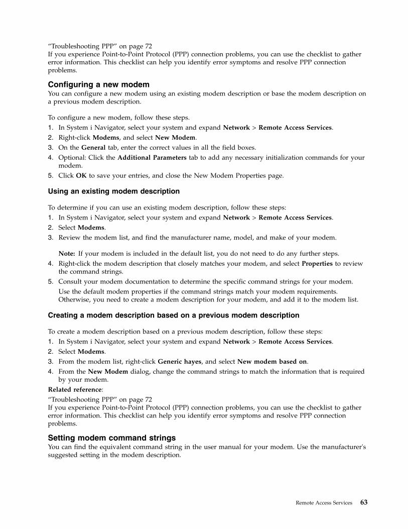
“Troubleshooting PPP” on page 72If you experience Point-to-Point Protocol (PPP) connection problems, you can use the checklist to gathererror information. This checklist can help you identify error symptoms and resolve PPP connectionproblems.
Configuring a new modemYou can configure a new modem using an existing modem description or base the modem description ona previous modem description.
To configure a new modem, follow these steps.1. In System i Navigator, select your system and expand Network > Remote Access Services.2. Right-click Modems, and select New Modem.3. On the General tab, enter the correct values in all the field boxes.4. Optional: Click the Additional Parameters tab to add any necessary initialization commands for your
modem.5. Click OK to save your entries, and close the New Modem Properties page.
Using an existing modem description
To determine if you can use an existing modem description, follow these steps:1. In System i Navigator, select your system and expand Network > Remote Access Services.2. Select Modems.3. Review the modem list, and find the manufacturer name, model, and make of your modem.
Note: If your modem is included in the default list, you do not need to do any further steps.4. Right-click the modem description that closely matches your modem, and select Properties to review
the command strings.5. Consult your modem documentation to determine the specific command strings for your modem.
Use the default modem properties if the command strings match your modem requirements.Otherwise, you need to create a modem description for your modem, and add it to the modem list.
Creating a modem description based on a previous modem description
To create a modem description based on a previous modem description, follow these steps:1. In System i Navigator, select your system and expand Network > Remote Access Services.2. Select Modems.3. From the modem list, right-click Generic hayes, and select New modem based on.4. From the New Modem dialog, change the command strings to match the information that is required
by your modem.Related reference:“Troubleshooting PPP” on page 72If you experience Point-to-Point Protocol (PPP) connection problems, you can use the checklist to gathererror information. This checklist can help you identify error symptoms and resolve PPP connectionproblems.
Setting modem command stringsYou can find the equivalent command string in the user manual for your modem. Use the manufacturer'ssuggested setting in the modem description.
Remote Access Services 63
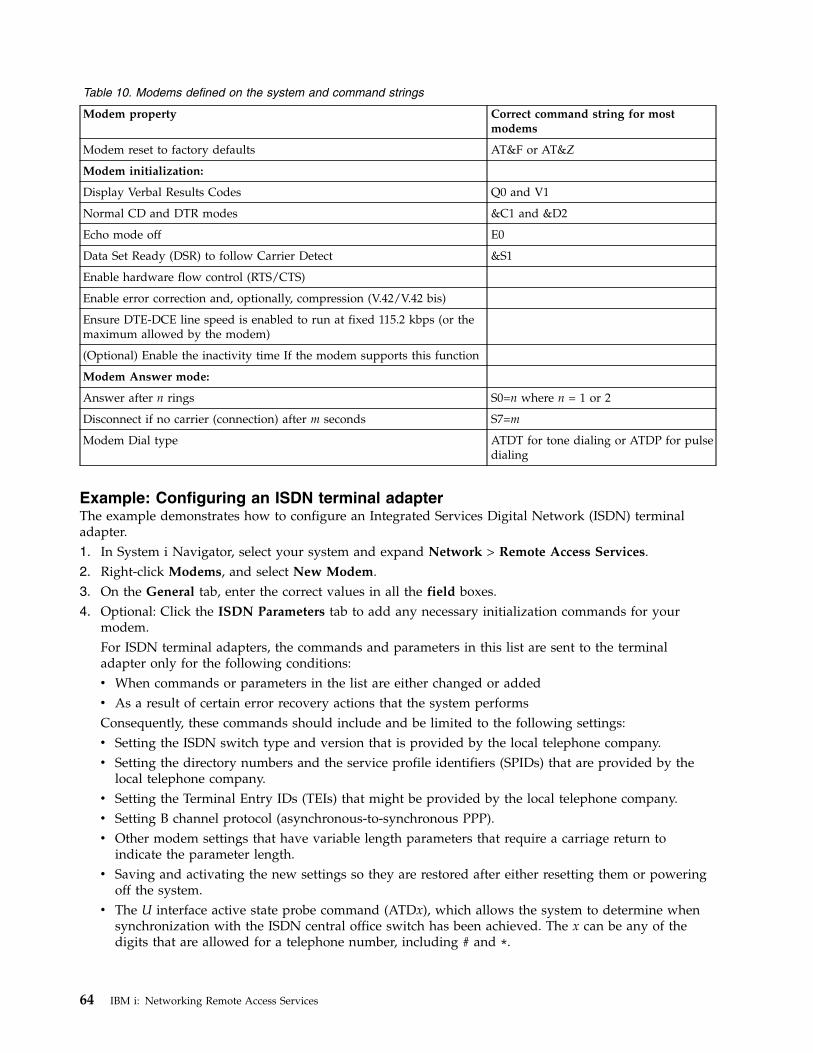
Table 10. Modems defined on the system and command strings
Modem property Correct command string for mostmodems
Modem reset to factory defaults AT&F or AT&Z
Modem initialization:
Display Verbal Results Codes Q0 and V1
Normal CD and DTR modes &C1 and &D2
Echo mode off E0
Data Set Ready (DSR) to follow Carrier Detect &S1
Enable hardware flow control (RTS/CTS)
Enable error correction and, optionally, compression (V.42/V.42 bis)
Ensure DTE-DCE line speed is enabled to run at fixed 115.2 kbps (or themaximum allowed by the modem)
(Optional) Enable the inactivity time If the modem supports this function
Modem Answer mode:
Answer after n rings S0=n where n = 1 or 2
Disconnect if no carrier (connection) after m seconds S7=m
Modem Dial type ATDT for tone dialing or ATDP for pulsedialing
Example: Configuring an ISDN terminal adapterThe example demonstrates how to configure an Integrated Services Digital Network (ISDN) terminaladapter.1. In System i Navigator, select your system and expand Network > Remote Access Services.2. Right-click Modems, and select New Modem.3. On the General tab, enter the correct values in all the field boxes.4. Optional: Click the ISDN Parameters tab to add any necessary initialization commands for your
modem.For ISDN terminal adapters, the commands and parameters in this list are sent to the terminaladapter only for the following conditions:v When commands or parameters in the list are either changed or addedv As a result of certain error recovery actions that the system performsConsequently, these commands should include and be limited to the following settings:v Setting the ISDN switch type and version that is provided by the local telephone company.v Setting the directory numbers and the service profile identifiers (SPIDs) that are provided by the
local telephone company.v Setting the Terminal Entry IDs (TEIs) that might be provided by the local telephone company.v Setting B channel protocol (asynchronous-to-synchronous PPP).v Other modem settings that have variable length parameters that require a carriage return to
indicate the parameter length.v Saving and activating the new settings so they are restored after either resetting them or powering
off the system.v The U interface active state probe command (ATDx), which allows the system to determine when
synchronization with the ISDN central office switch has been achieved. The x can be any of thedigits that are allowed for a telephone number, including # and *.
64 IBM i: Networking Remote Access Services
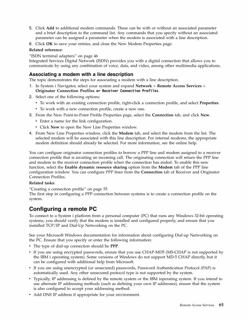
5. Click Add to additional modem commands. These can be with or without an associated parameterand a brief description to the command list. Any commands that you specify without an associatedparameter can be assigned a parameter when the modem is associated with a line description.
6. Click OK to save your entries, and close the New Modem Properties page.Related reference:“ISDN terminal adapters” on page 46Integrated Services Digital Network (ISDN) provides you with a digital connection that allows you tocommunicate by using any combination of voice, data, and video, among other multimedia applications.
Associating a modem with a line descriptionThe topic demonstrates the steps for associating a modem with a line description.1. In System i Navigator, select your system and expand Network > Remote Access Services >
Originator Connection Profiles or Receiver Connection Profiles.2. Select one of the following options:v To work with an existing connection profile, right-click a connection profile, and select Properties.v To work with a new connection profile, create a new one.
3. From the New Point-to-Point Profile Properties page, select the Connection tab, and click New.v Enter a name for the link configuration.v Click New to open the New Line Properties window.
4. From New Line Properties window, click the Modem tab, and select the modem from the list. Theselected modem will be associated with this line description. For internal modems, the appropriatemodem definition should already be selected. For more information, see the online help.
You can configure originator connection profiles to borrow a PPP line and modem assigned to a receiverconnection profile that is awaiting an incoming call. The originating connection will return the PPP lineand modem to the receiver connection profile when the connection has ended. To enable this newfunction, select the Enable dynamic resource sharing option from the Modem tab of the PPP lineconfiguration window. You can configure PPP lines from the Connection tab of Receiver and OriginatorConnection Profiles.Related tasks:“Creating a connection profile” on page 55The first step in configuring a PPP connection between systems is to create a connection profile on thesystem.
Configuring a remote PCTo connect to a System i platform from a personal computer (PC) that runs any Windows 32-bit operatingsystems, you should verify that the modem is installed and configured properly, and ensure that youinstalled TCP/IP and Dial-Up Networking on the PC.
See your Microsoft Windows documentation for information about configuring Dial-up Networking onthe PC. Ensure that you specify or enter the following information:v The type of dial-up connection should be PPP.v If you are using encrypted passwords, ensure that you use CHAP-MD5 (MS-CHAP is not supported by
the IBM i operating system). Some versions of Windows do not support MD-5 CHAP directly, but itcan be configured with additional help from Microsoft.
v If you are using unencrypted (or unsecured) passwords, Password Authentication Protocol (PAP) isautomatically used. Any other unsecured protocol type is not supported by the system.
v Typically, IP addressing is defined by the remote system or the IBM ioperating system. If you intend touse alternate IP addressing methods (such as defining your own IP addresses), ensure that the systemis also configured to accept your addressing method.
v Add DNS IP address if appropriate for your environment.
Remote Access Services 65
Configuring Internet access through the AT&T Global NetworkIf you want to communicate with the AT&T Global Network, you need to configure special profiles.
To access this service, you can use the AT&T Global Network Dial Connection wizard to help youconfigure a switched-dial PPP connection profile to dial the AT&T Global Network. The wizard walksyou through about eight panels and takes about ten minutes to complete. You can cancel the wizard atany time and no existing data is saved.
The following types of applications can use the AT&T Global Network connection:v Mail Exchange: It allows you to periodically retrieve mail from a single AT&T Global Network account
and send it to your system for distribution to your Lotus® Mail users or to your Simple Mail TransferProtocol (SMTP) users.
v Dial-up Networking: Use other dial-up networking applications with AT&T Global Network, such asstandard Internet access.
You maintain the AT&T Global Network connection profiles like any other PPP connection profiles.
You need one of these adapters to use the AT&T Global Network Dial Connection wizard:v 2699: Two-line WAN IOAv 2720: PCI WAN/Twinaxial IOAv 2721: PCI Two-line WAN IOAv 2745: PCI Two-line WAN IOA (replaces IOA 2721)v 2771: Two-port WAN IOA, with a V.90 integrated modem on port 1 and a standard communications
interface on port 2. To use port 2 of the 2771 adapter, an external modem or ISDN terminal adapterwith the appropriate cable is required.
v 2772: Two-port V.90 integrated modem WAN IOAv 2793/576C: Two-port WAN IOA, with a V.92 integrated modem on port 1 and a standard
communications interface on port 2. This replaces model 2771.v 2805: Four-port WAN IOA, with an integrated V.92 integrated modem. This replaces models 2761 and
2772.
Before starting the AT&T Global Network Dial Connection wizard, you need to collect this informationabout your environment:v The AT&T Global Network account information (account number, user ID, and password) for the mail
exchange application or the dial-up networking application.v The IP addresses of mail server and domain name server for the mail exchange application.v The name of the modem that is used for single line connections.
To start the AT&T Global Network Dial Connection wizard, follow these steps:1. In System i Navigator, expand your system and access Network > Remote Access Services.2. Right-click Originator Connection Profiles, and select New AT&T Global Network Dial Connection.3. When the AT&T Global Network Dial Connection wizard starts, click Help for information about
completing a panel.
Connection wizardsYou can use connection wizards to guide you through connection profile configuration.
New Dial Connection Wizard
This wizard describes the steps to configure a dial-up connection profile to access your ISP or intranet.You need to get some information from your network administrator or ISP to complete the wizard. For
66 IBM i: Networking Remote Access Services
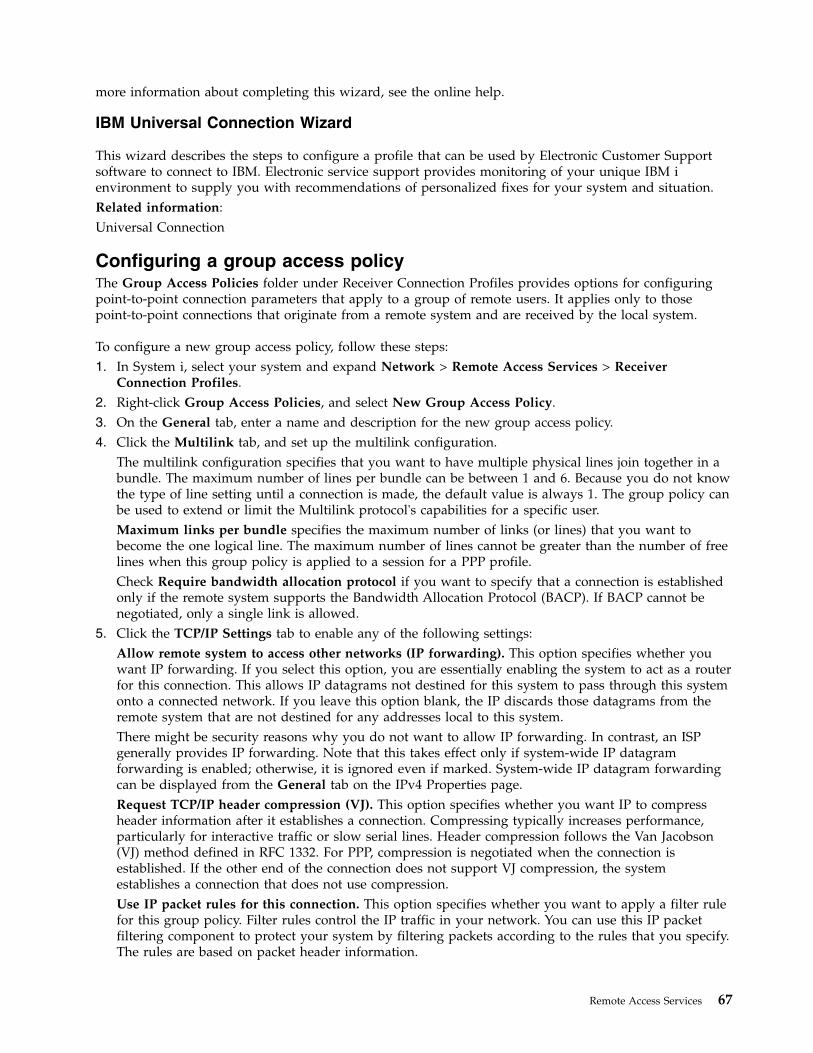
more information about completing this wizard, see the online help.
IBM Universal Connection Wizard
This wizard describes the steps to configure a profile that can be used by Electronic Customer Supportsoftware to connect to IBM. Electronic service support provides monitoring of your unique IBM ienvironment to supply you with recommendations of personalized fixes for your system and situation.Related information:Universal Connection
Configuring a group access policyThe Group Access Policies folder under Receiver Connection Profiles provides options for configuringpoint-to-point connection parameters that apply to a group of remote users. It applies only to thosepoint-to-point connections that originate from a remote system and are received by the local system.
To configure a new group access policy, follow these steps:1. In System i, select your system and expand Network > Remote Access Services > Receiver
Connection Profiles.2. Right-click Group Access Policies, and select New Group Access Policy.3. On the General tab, enter a name and description for the new group access policy.4. Click the Multilink tab, and set up the multilink configuration.
The multilink configuration specifies that you want to have multiple physical lines join together in abundle. The maximum number of lines per bundle can be between 1 and 6. Because you do not knowthe type of line setting until a connection is made, the default value is always 1. The group policy canbe used to extend or limit the Multilink protocol's capabilities for a specific user.Maximum links per bundle specifies the maximum number of links (or lines) that you want tobecome the one logical line. The maximum number of lines cannot be greater than the number of freelines when this group policy is applied to a session for a PPP profile.Check Require bandwidth allocation protocol if you want to specify that a connection is establishedonly if the remote system supports the Bandwidth Allocation Protocol (BACP). If BACP cannot benegotiated, only a single link is allowed.
5. Click the TCP/IP Settings tab to enable any of the following settings:Allow remote system to access other networks (IP forwarding). This option specifies whether youwant IP forwarding. If you select this option, you are essentially enabling the system to act as a routerfor this connection. This allows IP datagrams not destined for this system to pass through this systemonto a connected network. If you leave this option blank, the IP discards those datagrams from theremote system that are not destined for any addresses local to this system.There might be security reasons why you do not want to allow IP forwarding. In contrast, an ISPgenerally provides IP forwarding. Note that this takes effect only if system-wide IP datagramforwarding is enabled; otherwise, it is ignored even if marked. System-wide IP datagram forwardingcan be displayed from the General tab on the IPv4 Properties page.Request TCP/IP header compression (VJ). This option specifies whether you want IP to compressheader information after it establishes a connection. Compressing typically increases performance,particularly for interactive traffic or slow serial lines. Header compression follows the Van Jacobson(VJ) method defined in RFC 1332. For PPP, compression is negotiated when the connection isestablished. If the other end of the connection does not support VJ compression, the systemestablishes a connection that does not use compression.Use IP packet rules for this connection. This option specifies whether you want to apply a filter rulefor this group policy. Filter rules control the IP traffic in your network. You can use this IP packetfiltering component to protect your system by filtering packets according to the rules that you specify.The rules are based on packet header information.
Remote Access Services 67
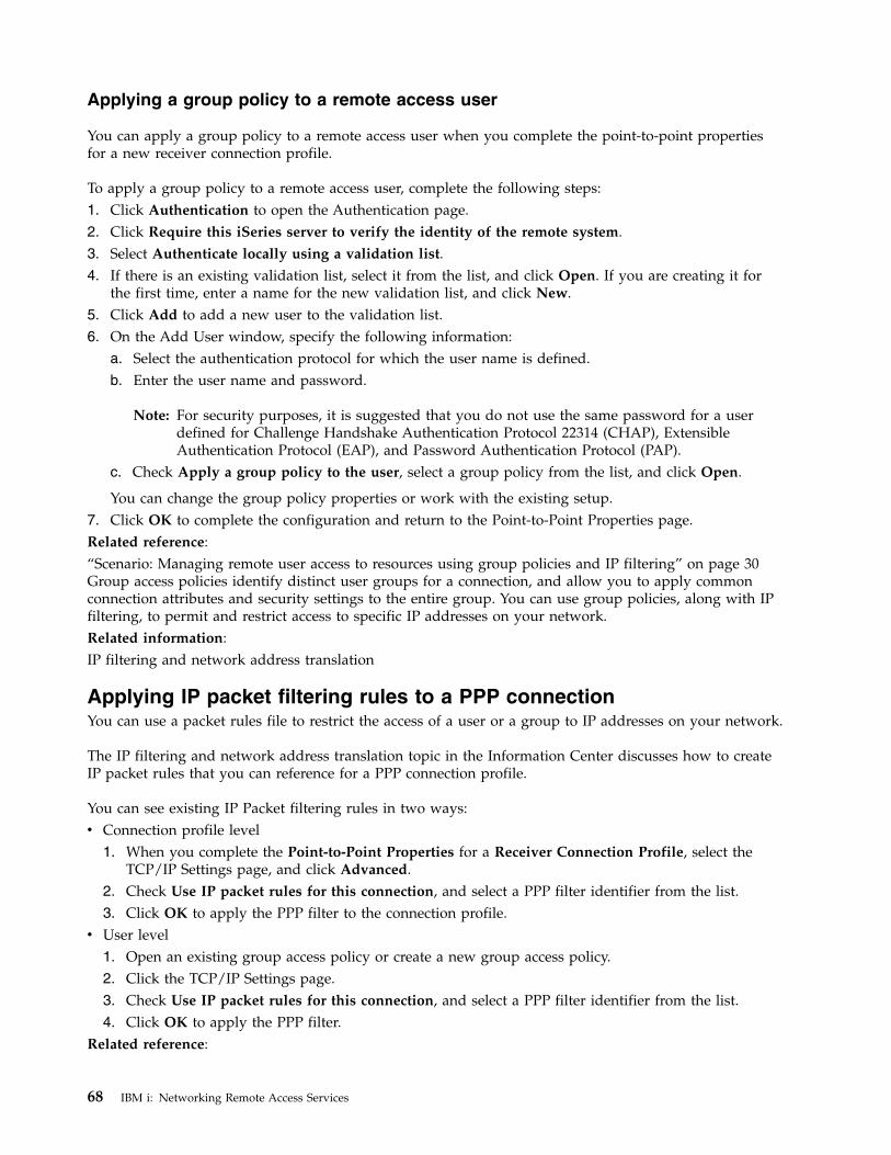
Applying a group policy to a remote access user
You can apply a group policy to a remote access user when you complete the point-to-point propertiesfor a new receiver connection profile.
To apply a group policy to a remote access user, complete the following steps:1. Click Authentication to open the Authentication page.2. Click Require this iSeries server to verify the identity of the remote system.3. Select Authenticate locally using a validation list.4. If there is an existing validation list, select it from the list, and click Open. If you are creating it for
the first time, enter a name for the new validation list, and click New.5. Click Add to add a new user to the validation list.6. On the Add User window, specify the following information:
a. Select the authentication protocol for which the user name is defined.b. Enter the user name and password.
Note: For security purposes, it is suggested that you do not use the same password for a userdefined for Challenge Handshake Authentication Protocol 22314 (CHAP), ExtensibleAuthentication Protocol (EAP), and Password Authentication Protocol (PAP).
c. Check Apply a group policy to the user, select a group policy from the list, and click Open.
You can change the group policy properties or work with the existing setup.7. Click OK to complete the configuration and return to the Point-to-Point Properties page.Related reference:“Scenario: Managing remote user access to resources using group policies and IP filtering” on page 30Group access policies identify distinct user groups for a connection, and allow you to apply commonconnection attributes and security settings to the entire group. You can use group policies, along with IPfiltering, to permit and restrict access to specific IP addresses on your network.Related information:IP filtering and network address translation
Applying IP packet filtering rules to a PPP connectionYou can use a packet rules file to restrict the access of a user or a group to IP addresses on your network.
The IP filtering and network address translation topic in the Information Center discusses how to createIP packet rules that you can reference for a PPP connection profile.
You can see existing IP Packet filtering rules in two ways:v Connection profile level
1. When you complete the Point-to-Point Properties for a Receiver Connection Profile, select theTCP/IP Settings page, and click Advanced.
2. Check Use IP packet rules for this connection, and select a PPP filter identifier from the list.3. Click OK to apply the PPP filter to the connection profile.
v User level1. Open an existing group access policy or create a new group access policy.2. Click the TCP/IP Settings page.3. Check Use IP packet rules for this connection, and select a PPP filter identifier from the list.4. Click OK to apply the PPP filter.
Related reference:
68 IBM i: Networking Remote Access Services
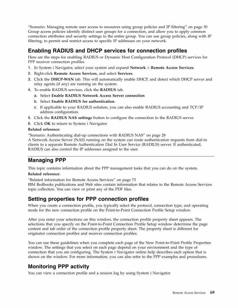
“Scenario: Managing remote user access to resources using group policies and IP filtering” on page 30Group access policies identify distinct user groups for a connection, and allow you to apply commonconnection attributes and security settings to the entire group. You can use group policies, along with IPfiltering, to permit and restrict access to specific IP addresses on your network.
Enabling RADIUS and DHCP services for connection profilesHere are the steps for enabling RADIUS or Dynamic Host Configuration Protocol (DHCP) services forPPP receiver connection profiles.1. In System i Navigator, select your system and expand Network > Remote Access Services.2. Right-click Remote Access Services, and select Services.3. Click the DHCP-WAN tab. This will automatically enable DHCP, and detect which DHCP server and
relay agents (if any) are running on the system.4. To enable RADIUS services, click the RADIUS tab.
a. Select Enable RADIUS Network Access Server connection
b. Select Enable RADIUS for authentication.c. If applicable to your RADIUS solution, you can also enable RADIUS accounting and TCP/IP
address configuration.5. Click the RADIUS NAS settings button to configure the connection to the RADIUS server.6. Click OK to return to System i Navigator.Related reference:“Scenario: Authenticating dial-up connections with RADIUS NAS” on page 28A Network Access Server (NAS) running on the system can route authentication requests from dial-inclients to a separate Remote Authentication Dial In User Service (RADIUS) server. If authenticated,RADIUS can also control the IP addresses assigned to the user.
Managing PPPThis topic contains information about the PPP management tasks that you can do on the system.Related reference:“Related information for Remote Access Services” on page 73IBM Redbooks publications and Web sites contain information that relates to the Remote Access Servicestopic collection. You can view or print any of the PDF files.
Setting properties for PPP connection profilesWhen you create a connection profile, you typically select the protocol, connection type, and operatingmode for the new connection profile on the Point-to-Point Connection Profile Setup window.
After you enter your selections on this window, the connection profile property sheet appears. Theselections that you specify on the Point-to-Point Connection Profile Setup window determine the pagecontent and tab order of the connection profile property sheet. The property sheet is different fororiginator connection profiles and receiver connection profiles.
You can use these guidelines when you complete each page of the New Point-to-Point Profile Propertieswindow. The settings that you select on each page depend on your environment and the type ofconnection that you are configuring. The System i Navigator online help describes each option that isshown on the window. For more information, you can also refer to the PPP examples and procedures.
Monitoring PPP activityYou can view a connection profile and a session log by using System i Navigator.
Remote Access Services 69
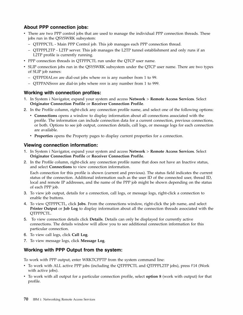
About PPP connection jobs:v There are two PPP control jobs that are used to manage the individual PPP connection threads. These
jobs run in the QSYSWRK subsystem:– QTPPPCTL - Main PPP Control job. This job manages each PPP connection thread.– QTPPPL2TP - L2TP server. This job manages the L2TP tunnel establishment and only runs if an
L2TP profile is currently running.v PPP connection threads in QTPPPCTL run under the QTCP user name.v SLIP connection jobs run in the QSYSWRK subsystem under the QTCP user name. There are two types
of SLIP job names:– QTPPDIALnn are dial-out jobs where nn is any number from 1 to 99.– QTPPANSnnn are dial-in jobs where nnn is any number from 1 to 999.
Working with connection profiles:1. In System i Navigator, expand your system and access Network > Remote Access Services. Select
Originator Connection Profile or Receiver Connection Profile.2. In the Profile column, right-click any connection profile name, and select one of the following options:v Connections opens a window to display information about all connections associated with the
profile. The information can include connection data for a current connection, previous connections,or both. Options to see job output, connection details, call logs, or message logs for each connectionare available.
v Properties opens the Property pages to display current properties for a connection.
Viewing connection information:1. In System i Navigator, expand your system and access Network > Remote Access Services. Select
Originator Connection Profile or Receiver Connection Profile.2. In the Profile column, right-click any connection profile name that does not have an Inactive status,
and select Connections to view connection information.Each connection for this profile is shown (current and previous). The status field indicates the currentstatus of the connection. Additional information such as the user ID of the connected user, thread ID,local and remote IP addresses, and the name of the PPP job might be shown depending on the statusof each PPP job.
3. To view job output, details for a connection, call logs, or message logs, right-click a connection toenable the buttons.
4. To view QTPPPCTL, click Jobs. From the connections window, right-click the job name, and selectPrinter Output or Job Log to display information about all the connection threads associated with theQTPPPCTL.
5. To view connection details click Details. Details can only be displayed for currently activeconnections. The details window will allow you to see additional connection information for thisparticular connection.
6. To view call logs, click Call Log.7. To view message logs, click Message Log.
Working with PPP Output from the system:
To work with PPP output, enter WRKTCPPTP from the system command line:v To work with ALL active PPP jobs (including the QTPPPCTL and QTPPPL2TP jobs), press F14 (Work
with active jobs).v To work with all output for a particular connection profile, select option 8 (work with output) for that
profile.
70 IBM i: Networking Remote Access Services
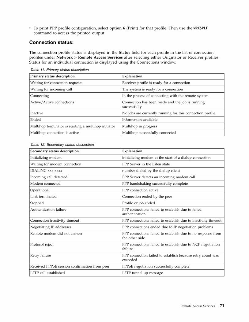
v To print PPP profile configuration, select option 6 (Print) for that profile. Then use the WRKSPLFcommand to access the printed output.
Connection status:
The connection profile status is displayed in the Status field for each profile in the list of connectionprofiles under Network > Remote Access Services after selecting either Originator or Receiver profiles.Status for an individual connection is displayed using the Connections window.
Table 11. Primary status description
Primary status description Explanation
Waiting for connection requests Receiver profile is ready for a connection
Waiting for incoming call The system is ready for a connection
Connecting In the process of connecting with the remote system
Active/Active connections Connection has been made and the job is runningsuccessfully
Inactive No jobs are currently running for this connection profile
Ended Information available
Multihop terminator is starting a multihop initiator Multihop in progress
Multihop connection is active Multihop successfully connected
Table 12. Secondary status description
Secondary status description Explanation
Initializing modem initializing modem at the start of a dialup connection
Waiting for modem connection PPP Server in the listen state
DIALING xxx-xxxx number dialed by the dialup client
Incoming call detected PPP Server detects an incoming modem call
Modem connected PPP handshaking successfully complete
Operational PPP connection active
Link terminated Connection ended by the peer
Stopped Profile or job ended
Authentication failure PPP connections failed to establish due to failedauthentication
Connection inactivity timeout PPP connections failed to establish due to inactivity timeout
Negotiating IP addresses PPP connections ended due to IP negotiation problems
Remote modem did not answer PPP connections failed to establish due to no response fromthe other side
Protocol reject PPP connections failed to establish due to NCP negotiationfailure
Retry failure PPP connection failed to establish because retry count wasexceeded
Received PPPoE session confirmation from peer PPPoE negotiation successfully complete
L2TP call established L2TP tunnel up message
Remote Access Services 71
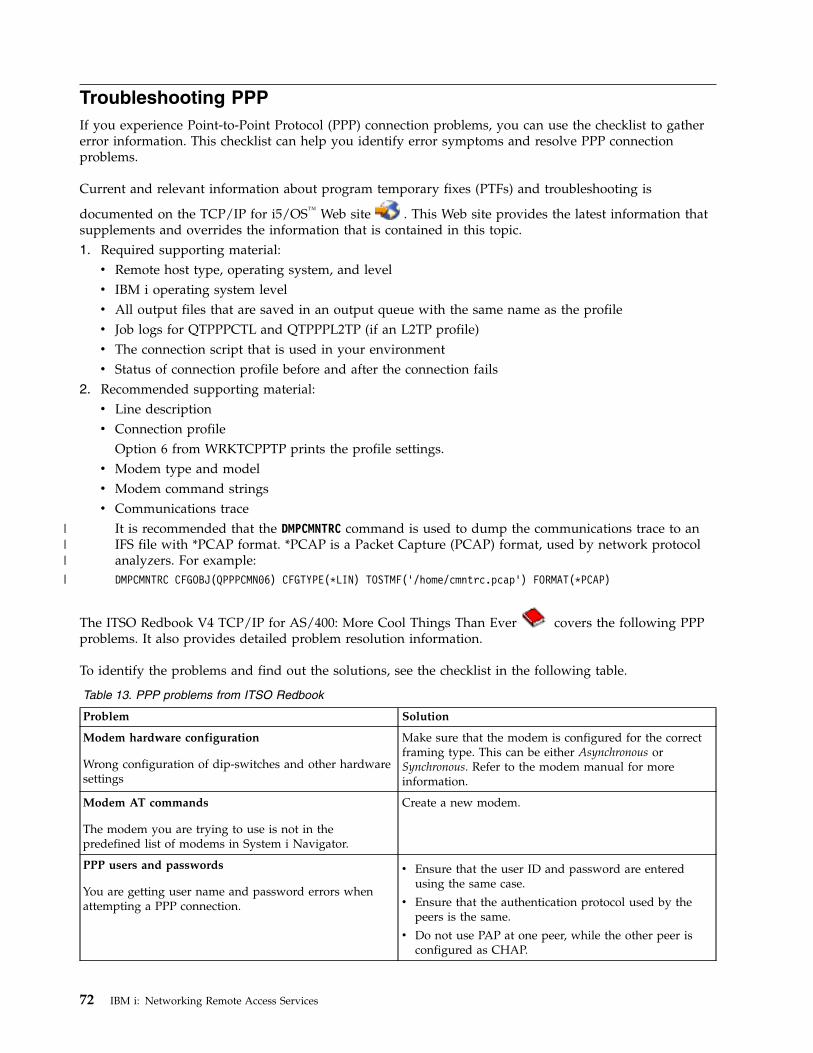
Troubleshooting PPPIf you experience Point-to-Point Protocol (PPP) connection problems, you can use the checklist to gathererror information. This checklist can help you identify error symptoms and resolve PPP connectionproblems.
Current and relevant information about program temporary fixes (PTFs) and troubleshooting is
documented on the TCP/IP for i5/OS™ Web site . This Web site provides the latest information thatsupplements and overrides the information that is contained in this topic.1. Required supporting material:v Remote host type, operating system, and levelv IBM i operating system levelv All output files that are saved in an output queue with the same name as the profilev Job logs for QTPPPCTL and QTPPPL2TP (if an L2TP profile)v The connection script that is used in your environmentv Status of connection profile before and after the connection fails
2. Recommended supporting material:v Line descriptionv Connection profile
Option 6 from WRKTCPPTP prints the profile settings.v Modem type and modelv Modem command stringsv Communications trace
It is recommended that the DMPCMNTRC command is used to dump the communications trace to anIFS file with *PCAP format. *PCAP is a Packet Capture (PCAP) format, used by network protocolanalyzers. For example:DMPCMNTRC CFGOBJ(QPPPCMN06) CFGTYPE(*LIN) TOSTMF(’/home/cmntrc.pcap’) FORMAT(*PCAP)
The ITSO Redbook V4 TCP/IP for AS/400: More Cool Things Than Ever
covers the following PPPproblems. It also provides detailed problem resolution information.
To identify the problems and find out the solutions, see the checklist in the following table.
Table 13. PPP problems from ITSO Redbook
Problem Solution
Modem hardware configuration
Wrong configuration of dip-switches and other hardwaresettings
Make sure that the modem is configured for the correctframing type. This can be either Asynchronous orSynchronous. Refer to the modem manual for moreinformation.
Modem AT commands
The modem you are trying to use is not in thepredefined list of modems in System i Navigator.
Create a new modem.
PPP users and passwords
You are getting user name and password errors whenattempting a PPP connection.
v Ensure that the user ID and password are enteredusing the same case.
v Ensure that the authentication protocol used by thepeers is the same.
v Do not use PAP at one peer, while the other peer isconfigured as CHAP.
72 IBM i: Networking Remote Access Services
|||
|
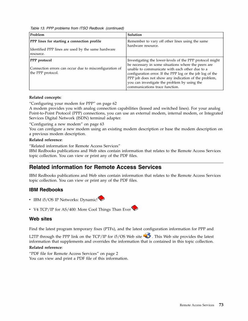
Table 13. PPP problems from ITSO Redbook (continued)
Problem Solution
PPP lines for starting a connection profile
Identified PPP lines are used by the same hardwareresource.
Remember to vary off other lines using the samehardware resource.
PPP protocol
Connection errors can occur due to misconfiguration ofthe PPP protocol.
Investigating the lower-levels of the PPP protocol mightbe necessary in some situations where the peers areunable to communicate with each other due to aconfiguration error. If the PPP log or the job log of thePPP job does not show any indication of the problem,you can investigate the problem by using thecommunications trace function.
Related concepts:“Configuring your modem for PPP” on page 62A modem provides you with analog connection capabilities (leased and switched lines). For your analogPoint-to-Point Protocol (PPP) connections, you can use an external modem, internal modem, or IntegratedServices Digital Network (ISDN) terminal adapter. “Configuring a new modem” on page 63You can configure a new modem using an existing modem description or base the modem description ona previous modem description.Related reference:“Related information for Remote Access Services”IBM Redbooks publications and Web sites contain information that relates to the Remote Access Servicestopic collection. You can view or print any of the PDF files.
Related information for Remote Access ServicesIBM Redbooks publications and Web sites contain information that relates to the Remote Access Servicestopic collection. You can view or print any of the PDF files.
IBM Redbooks
v IBM i5/OS IP Networks: Dynamic!
v V4 TCP/IP for AS/400: More Cool Things Than Ever
Web sites
Find the latest program temporary fixes (PTFs), and the latest configuration information for PPP and
L2TP through the PPP link on the TCP/IP for i5/OS Web site . This Web site provides the latestinformation that supplements and overrides the information that is contained in this topic collection.Related reference:“PDF file for Remote Access Services” on page 2You can view and print a PDF file of this information.
Remote Access Services 73

74 IBM i: Networking Remote Access Services
Appendix. Notices
This information was developed for products and services offered in the U.S.A.
IBM may not offer the products, services, or features discussed in this document in other countries.Consult your local IBM representative for information on the products and services currently available inyour area. Any reference to an IBM product, program, or service is not intended to state or imply thatonly that IBM product, program, or service may be used. Any functionally equivalent product, program,or service that does not infringe any IBM intellectual property right may be used instead. However, it isthe user's responsibility to evaluate and verify the operation of any non-IBM product, program, orservice.
IBM may have patents or pending patent applications covering subject matter described in thisdocument. The furnishing of this document does not grant you any license to these patents. You can sendlicense inquiries, in writing, to:
IBM Director of LicensingIBM CorporationNorth Castle DriveArmonk, NY 10504-1785U.S.A.
For license inquiries regarding double-byte (DBCS) information, contact the IBM Intellectual PropertyDepartment in your country or send inquiries, in writing, to:
Intellectual Property LicensingLegal and Intellectual Property LawIBM Japan, Ltd.3-2-12, Roppongi, Minato-ku, Tokyo 106-8711
The following paragraph does not apply to the United Kingdom or any other country where suchprovisions are inconsistent with local law: INTERNATIONAL BUSINESS MACHINES CORPORATIONPROVIDES THIS PUBLICATION “AS IS” WITHOUT WARRANTY OF ANY KIND, EITHER EXPRESSOR IMPLIED, INCLUDING, BUT NOT LIMITED TO, THE IMPLIED WARRANTIES OFNON-INFRINGEMENT, MERCHANTABILITY OR FITNESS FOR A PARTICULAR PURPOSE. Somestates do not allow disclaimer of express or implied warranties in certain transactions, therefore, thisstatement may not apply to you.
This information could include technical inaccuracies or typographical errors. Changes are periodicallymade to the information herein; these changes will be incorporated in new editions of the publication.IBM may make improvements and/or changes in the product(s) and/or the program(s) described in thispublication at any time without notice.
Any references in this information to non-IBM Web sites are provided for convenience only and do not inany manner serve as an endorsement of those Web sites. The materials at those Web sites are not part ofthe materials for this IBM product and use of those Web sites is at your own risk.
IBM may use or distribute any of the information you supply in any way it believes appropriate withoutincurring any obligation to you.
Licensees of this program who wish to have information about it for the purpose of enabling: (i) theexchange of information between independently created programs and other programs (including thisone) and (ii) the mutual use of the information which has been exchanged, should contact:
IBM Corporation
© Copyright IBM Corp. 1998, 2010 75
Software Interoperability Coordinator, Department YBWA3605 Highway 52 NRochester, MN 55901U.S.A.
Such information may be available, subject to appropriate terms and conditions, including in some cases,payment of a fee.
The licensed program described in this document and all licensed material available for it are providedby IBM under terms of the IBM Customer Agreement, IBM International Program License Agreement,IBM License Agreement for Machine Code, or any equivalent agreement between us.
Any performance data contained herein was determined in a controlled environment. Therefore, theresults obtained in other operating environments may vary significantly. Some measurements may havebeen made on development-level systems and there is no guarantee that these measurements will be thesame on generally available systems. Furthermore, some measurements may have been estimated throughextrapolation. Actual results may vary. Users of this document should verify the applicable data for theirspecific environment.
Information concerning non-IBM products was obtained from the suppliers of those products, theirpublished announcements or other publicly available sources. IBM has not tested those products andcannot confirm the accuracy of performance, compatibility or any other claims related to non-IBMproducts. Questions on the capabilities of non-IBM products should be addressed to the suppliers ofthose products.
All statements regarding IBM's future direction or intent are subject to change or withdrawal withoutnotice, and represent goals and objectives only.
All IBM prices shown are IBM's suggested retail prices, are current and are subject to change withoutnotice. Dealer prices may vary.
This information is for planning purposes only. The information herein is subject to change before theproducts described become available.
This information contains examples of data and reports used in daily business operations. To illustratethem as completely as possible, the examples include the names of individuals, companies, brands, andproducts. All of these names are fictitious and any similarity to the names and addresses used by anactual business enterprise is entirely coincidental.
COPYRIGHT LICENSE:
This information contains sample application programs in source language, which illustrate programmingtechniques on various operating platforms. You may copy, modify, and distribute these sample programsin any form without payment to IBM, for the purposes of developing, using, marketing or distributingapplication programs conforming to the application programming interface for the operating platform forwhich the sample programs are written. These examples have not been thoroughly tested under allconditions. IBM, therefore, cannot guarantee or imply reliability, serviceability, or function of theseprograms. The sample programs are provided "AS IS", without warranty of any kind. IBM shall not beliable for any damages arising out of your use of the sample programs.
Each copy or any portion of these sample programs or any derivative work, must include a copyrightnotice as follows:
© (your company name) (year). Portions of this code are derived from IBM Corp. Sample Programs. ©Copyright IBM Corp. _enter the year or years_.
76 IBM i: Networking Remote Access Services
If you are viewing this information softcopy, the photographs and color illustrations may not appear.
Programming interface informationThis Remote Access Services publication documents intended Programming Interfaces that allow thecustomer to write programs to obtain the services of IBM i.
TrademarksIBM, the IBM logo, and ibm.com are trademarks or registered trademarks of International BusinessMachines Corp., registered in many jurisdictions worldwide. Other product and service names might betrademarks of IBM or other companies. A current list of IBM trademarks is available on the Web atCopyright and trademark information at www.ibm.com/legal/copytrade.shtml.
Adobe, the Adobe logo, PostScript, and the PostScript logo are either registered trademarks or trademarksof Adobe Systems Incorporated in the United States, and/or other countries.
Linux is a registered trademark of Linus Torvalds in the United States, other countries, or both.
Microsoft, Windows, Windows NT, and the Windows logo are trademarks of Microsoft Corporation in theUnited States, other countries, or both.
UNIX is a registered trademark of The Open Group in the United States and other countries.
Other company, product, or service names may be trademarks or service marks of others.
Terms and conditionsPermissions for the use of these publications is granted subject to the following terms and conditions.
Personal Use: You may reproduce these publications for your personal, noncommercial use provided thatall proprietary notices are preserved. You may not distribute, display or make derivative works of thesepublications, or any portion thereof, without the express consent of IBM.
Commercial Use: You may reproduce, distribute and display these publications solely within yourenterprise provided that all proprietary notices are preserved. You may not make derivative works ofthese publications, or reproduce, distribute or display these publications or any portion thereof outsideyour enterprise, without the express consent of IBM.
Except as expressly granted in this permission, no other permissions, licenses or rights are granted, eitherexpress or implied, to the publications or any information, data, software or other intellectual propertycontained therein.
IBM reserves the right to withdraw the permissions granted herein whenever, in its discretion, the use ofthe publications is detrimental to its interest or, as determined by IBM, the above instructions are notbeing properly followed.
You may not download, export or re-export this information except in full compliance with all applicablelaws and regulations, including all United States export laws and regulations.
IBM MAKES NO GUARANTEE ABOUT THE CONTENT OF THESE PUBLICATIONS. THEPUBLICATIONS ARE PROVIDED "AS-IS" AND WITHOUT WARRANTY OF ANY KIND, EITHEREXPRESSED OR IMPLIED, INCLUDING BUT NOT LIMITED TO IMPLIED WARRANTIES OFMERCHANTABILITY, NON-INFRINGEMENT, AND FITNESS FOR A PARTICULAR PURPOSE.
Appendix. Notices 77

78 IBM i: Networking Remote Access Services


IBM®
Printed in USA