Embed Size (px)
Citation preview
Registro Mercantil de Madrid, Tomo 12390. Libro 0. Folio 19. Sección 89. Hoja M-33690 – CIF: A-28/286375
www.enusa.es
Sede Social Madrid
Santiago Rusiñol, 12
28040 Madrid
Tel.: 91 347 42 00 . Fax: 91 347 42 15
Ian C. Gauld Reactor Analysis Group, Nuclar Science and Technology Division Oak Ridge National Laboratory Ref: COM-006998 Rev. 2 Date: 02/12/2010 Dear Mr. Gauld Based on the Oak Ridge National Laboratory-ENUSA contract, number 4000049598, and the Memoradum of Agreement, MOA-UTB-2007005, ENUSA has provided in the previous revisions of this letter, the necessary information for validating computer code models. Furthermore, your letter dated on November 18, 2010 from I. Gauld to JM Alonso Pacheco, requests further data, already included in ITEC-1185 and issued to ORNL, for the purpose of validating computer code. Therefore, under the conditions stated in the above mentioned contract and MOA, this letter compiles the previously delivered data and the just requested one. Sincerely M. Quecedo Mgr, Product Engineering cc: G.Illas (ORNL) JM Conde (CSN) JA Gago (ANAV) C. Alejano (CSN) JM Alonso Attachment INF-TD-005933
ENUSA Proprietary
INF-TD-005933
Pág. 1/12
www.enusa.es
TABLE OF CONTENTS
1 Introduction .................................................................................................. 2
2 Irradiation cycles.......................................................................................... 2
3 Loading positions......................................................................................... 3
4 Rod data ...................................................................................................... 4
5 Fuel assembly data...................................................................................... 5
6 Burnable absorbers ..................................................................................... 8
7 Boron concentration..................................................................................... 9
8 Additional information ................................................................................ 10
ENUSA Proprietary
INF-TD-005933
Pág. 2/12
IRRADIATION DATA OF THE THREE FUEL RODS FOR HIGH BURNUP FUEL ISOTOPE DETERMINATION
Introduction This document provides information on irradiation history and burnup of the rods utilized in the framework of the High Burnup Fuel Isotope Determination Project (both phase I and II). The data which is provided in this document corresponds to the correct rods that were analyzed at Studsvik. These rods are: WZtR165, WZR0058 and WZtR160. Note that rods WZtR165 and WZR0058 were employed in the phase I of the project, while rod WZtR160 in phase II. The scope of Phase II included a reanalysis of the isotopic content of rod WZR0058. It is remarked that the outcome of the High Burnup Fuel Isotope Determination Project has been affected by a mismatch of rod identification which happened once the rods were shipped to the Studsvik hot cell facility. Thus, the original rods which were intended to be analyzed, WMtR124, WZR0046 and WMtR113 were exchanged with, respectively, WZtR165, WZR0058 and WZtR160. Thus, all the results produced so far are related to these rods.
Irradiation cycles The three rods were irradiated in Vandellós 2 during the reactor cycles 7 to 11. The following table summarises the cycle lengths and core burnup increments.
Cycle BU
(MWd/tU) BOC (date)
EOC (date)
Cycle length (calendar
days)
Core Average LHR (kW/m)
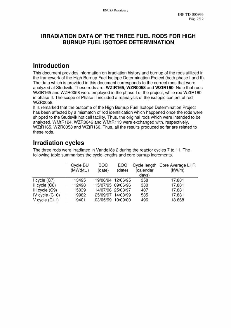
I cycle (C7) 13495 19/06/94 12/06/95 358 17.881 II cycle (C8) 12498 15/07/95 09/06/96 330 17.881 III cycle (C9) 15039 14/07/96 25/08/97 407 17.881 IV cycle (C10) 19982 25/09/97 14/03/99 535 17.881 V cycle (C11) 19401 03/05/99 10/09/00 496 18.668
ENUSA Proprietary
INF-TD-005933
Pág. 3/12
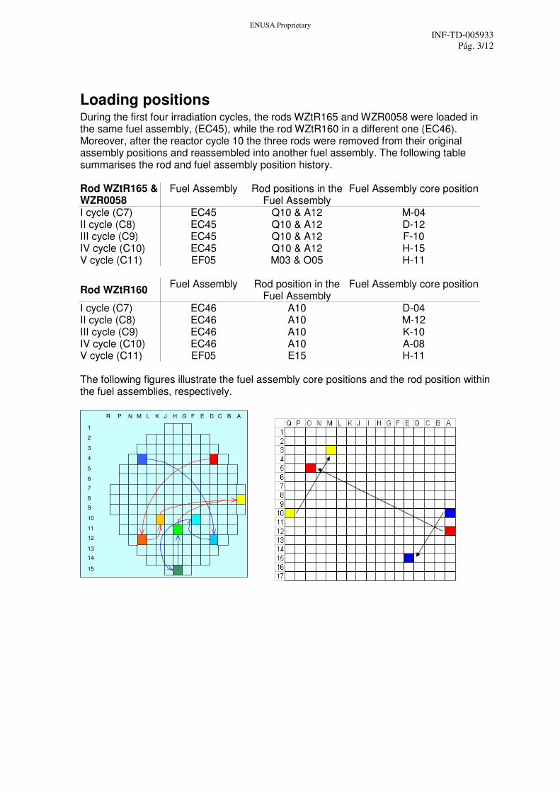
Loading positions During the first four irradiation cycles, the rods WZtR165 and WZR0058 were loaded in the same fuel assembly, (EC45), while the rod WZtR160 in a different one (EC46). Moreover, after the reactor cycle 10 the three rods were removed from their original assembly positions and reassembled into another fuel assembly. The following table summarises the rod and fuel assembly position history. Rod WZtR165 & WZR0058
Fuel Assembly Rod positions in the Fuel Assembly
Fuel Assembly core position
I cycle (C7) EC45 Q10 & A12 M-04 II cycle (C8) EC45 Q10 & A12 D-12 III cycle (C9) EC45 Q10 & A12 F-10 IV cycle (C10) EC45 Q10 & A12 H-15 V cycle (C11) EF05 M03 & O05 H-11
Rod WZtR160 Fuel Assembly Rod position in the
Fuel Assembly Fuel Assembly core position
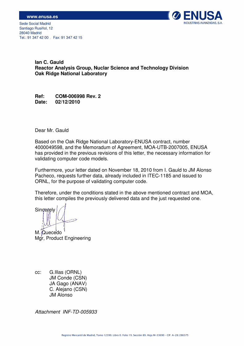
I cycle (C7) EC46 A10 D-04 II cycle (C8) EC46 A10 M-12 III cycle (C9) EC46 A10 K-10 IV cycle (C10) EC46 A10 A-08 V cycle (C11) EF05 E15 H-11 The following figures illustrate the fuel assembly core positions and the rod position within the fuel assemblies, respectively.
J H G FKL EM D CN BP AR
1
2
3
4
5
6
7
8
9
10
11
12
13
14
15
ENUSA Proprietary
INF-TD-005933
Pág. 4/12
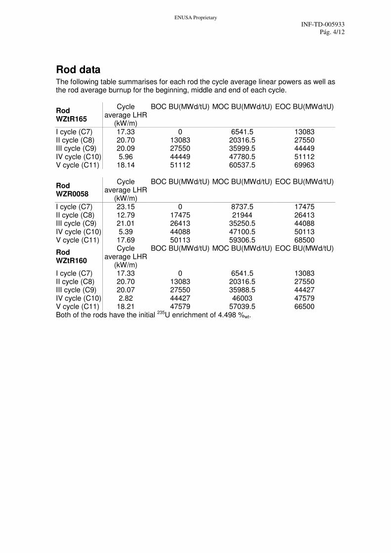
Rod data The following table summarises for each rod the cycle average linear powers as well as the rod average burnup for the beginning, middle and end of each cycle.
Rod WZtR165
Cycle average LHR
(kW/m)
BOC BU(MWd/tU) MOC BU(MWd/tU) EOC BU(MWd/tU)
I cycle (C7) 17.33 0 6541.5 13083 II cycle (C8) 20.70 13083 20316.5 27550 III cycle (C9) 20.09 27550 35999.5 44449 IV cycle (C10) 5.96 44449 47780.5 51112 V cycle (C11) 18.14 51112 60537.5 69963
Rod WZR0058
Cycle average LHR
(kW/m)
BOC BU(MWd/tU) MOC BU(MWd/tU) EOC BU(MWd/tU)
I cycle (C7) 23.15 0 8737.5 17475 II cycle (C8) 12.79 17475 21944 26413 III cycle (C9) 21.01 26413 35250.5 44088 IV cycle (C10) 5.39 44088 47100.5 50113 V cycle (C11) 17.69 50113 59306.5 68500
Rod WZtR160
Cycle average LHR
(kW/m)
BOC BU(MWd/tU) MOC BU(MWd/tU) EOC BU(MWd/tU)
I cycle (C7) 17.33 0 6541.5 13083 II cycle (C8) 20.70 13083 20316.5 27550 III cycle (C9) 20.07 27550 35988.5 44427 IV cycle (C10) 2.82 44427 46003 47579 V cycle (C11) 18.21 47579 57039.5 66500 Both of the rods have the initial 235U enrichment of 4.498 %wt.
ENUSA Proprietary
INF-TD-005933
Pág. 5/12
Fuel assembly data In addition to the fuel assemblies accommodating the analysed fuel rods, it is of importance to consider the effect of the adjacent assemblies as well. The fuel assemblies were neighboured each by another four assemblies interfacing the assembly edges in each cycle with the exception of cycle 10 where the accommodating assemblies were located in the core periphery. The following table presents the assembly average burnup, number of cycles, 235U enrichment, and burnable absorber configurations for the assemblies accommodating the analysed rods and the four (three in cycle 10) adjacent assemblies. The relative locations of adjacent assemblies are indicated as N (north), E (east), S (south) and W (west) with reference to the core scheme presented in the figure in the chapter 0.
ENUSA Proprietary
INF-TD-005933
Pág. 6/12
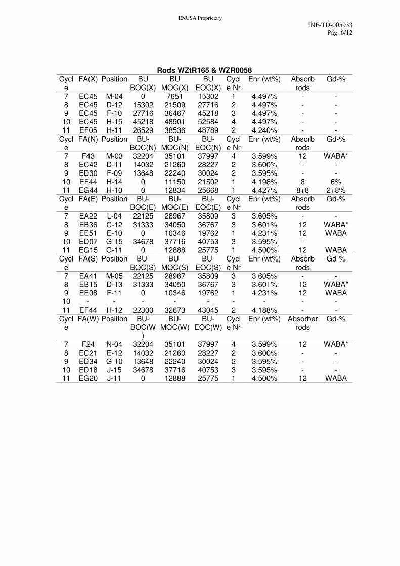
Rods WZtR165 & WZR0058
Cycle
FA(X) Position BU BOC(X)
BU MOC(X)
BU EOC(X)
Cycle Nr
Enr (wt%) Absorb rods
Gd-%
7 EC45 M-04 0 7651 15302 1 4.497% - - 8 EC45 D-12 15302 21509 27716 2 4.497% - - 9 EC45 F-10 27716 36467 45218 3 4.497% - - 10 EC45 H-15 45218 48901 52584 4 4.497% - - 11 EF05 H-11 26529 38536 48789 2 4.240% - -
Cycle
FA(N) Position BU-BOC(N)
BU-MOC(N)
BU-EOC(N)
Cycle Nr
Enr (wt%) Absorb rods
Gd-%
7 F43 M-03 32204 35101 37997 4 3.599% 12 WABA* 8 EC42 D-11 14032 21260 28227 2 3.600% - - 9 ED30 F-09 13648 22240 30024 2 3.595% - - 10 EF44 H-14 0 11150 21502 1 4.198% 8 6% 11 EG44 H-10 0 12834 25668 1 4.427% 8+8 2+8%
Cycle
FA(E) Position BU-BOC(E)
BU-MOC(E)
BU-EOC(E)
Cycle Nr
Enr (wt%) Absorb rods
Gd-%
7 EA22 L-04 22125 28967 35809 3 3.605% - - 8 EB36 C-12 31333 34050 36767 3 3.601% 12 WABA* 9 EE51 E-10 0 10346 19762 1 4.231% 12 WABA 10 ED07 G-15 34678 37716 40753 3 3.595% - - 11 EG15 G-11 0 12888 25775 1 4.500% 12 WABA
Cycle
FA(S) Position BU-BOC(S)
BU-MOC(S)
BU-EOC(S)
Cycle Nr
Enr (wt%) Absorb rods
Gd-%
7 EA41 M-05 22125 28967 35809 3 3.605% - - 8 EB15 D-13 31333 34050 36767 3 3.601% 12 WABA* 9 EE08 F-11 0 10346 19762 1 4.231% 12 WABA 10 - - - - - - - - - 11 EF44 H-12 22300 32673 43045 2 4.188% - -
Cycle
FA(W) Position BU-BOC(W
)
BU-MOC(W)
BU-EOC(W)
Cycle Nr
Enr (wt%) Absorber rods
Gd-%
7 F24 N-04 32204 35101 37997 4 3.599% 12 WABA* 8 EC21 E-12 14032 21260 28227 2 3.600% - - 9 ED34 G-10 13648 22240 30024 2 3.595% - - 10 ED18 J-15 34678 37716 40753 3 3.595% - - 11 EG20 J-11 0 12888 25775 1 4.500% 12 WABA
ENUSA Proprietary
INF-TD-005933
Pág. 7/12
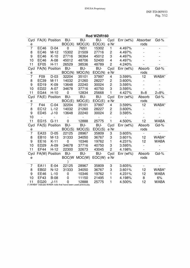
Rod WZtR160 Cycl
e FA(X) Position BU-
BOC(X) BU-
MOC(X) BU-
EOC(X) Cycle Nr
Enr (wt%) Absorber rods
Gd-%
7 EC46 D-04 0 7651 15302 1 4.497% - - 8 EC46 M-12 15302 21509 27716 2 4.497% - - 9 EC46 K-10 27716 36364 45012 3 4.497% - - 10 EC46 A-08 45012 48706 52400 4 4.497% - - 11 EF05 H-11 26529 38536 48789 2 4.240% - -
Cycle
FA(N) Position BU-BOC(N)
BU-MOC(N)
BU-EOC(N)
Cycle Nr
Enr (wt%) Absorb rods
Gd-%
7 F09 D-03 32204 35101 37997 4 3.599% 12 WABA* 8 EC39 M-11 14032 21260 28227 2 3.600% - - 9 ED19 K-09 13648 22240 30024 2 3.595% - - 10 ED22 A-07 34678 37716 40750 3 3.595% - - 11 EG44 H-10 0 12834 25668 1 4.427% 8+8 2+8%
Cycle
FA(E) Position BU-BOC(E)
BU-MOC(E)
BU-EOC(E)
Cycle Nr
Enr (wt%) Absorb rods
Gd-%
7 F44 C-04 32204 35101 37997 4 3.599% 12 WABA* 8 EC12 L-12 14032 21260 28227 2 3.600% - - 9 ED45 J-10 13648 22240 30024 2 3.595% - - 10 - - - - - - - - - 11 EG15 G-11 0 12888 25775 1 4.500% 12 WABA
Cycle
FA(S) Position BU-BOC(S)
BU-MOC(S)
BU-EOC(S)
Cycle Nr
Enr (wt%) Absorb rods
Gd-%
7 EA33 D-05 22125 28967 35809 3 3.605% - - 8 EB10 M-13 31333 34050 36767 3 3.601% 12 WABA* 9 EE16 K-11 0 10346 19762 1 4.231% 12 WABA 10 ED29 A-09 34678 37716 40750 3 3.595% - - 11 EF44 H-12 22300 32673 43045 2 4.198% - -
Cycle
FA(W) Position BU-BOC(W
)
BU-MOC(W)
BU-EOC(W)
Cycle Nr
Enr (wt%) Absorb rods
Gd-%
7 EA11 E-04 22125 28967 35809 3 3.605% - - 8 EB02 N-12 31333 34050 36767 3 3.601% 12 WABA* 9 EE46 L-10 0 10346 19762 1 4.231% 12 WABA 10 EF43 B-08 0 11150 21495 1 4.198% 8 6% 11 EG20 J-11 0 12888 25775 1 4.500% 12 WABA
(*) WABA* indicate WABA rods that have been used previously.
ENUSA Proprietary
INF-TD-005933
Pág. 8/12
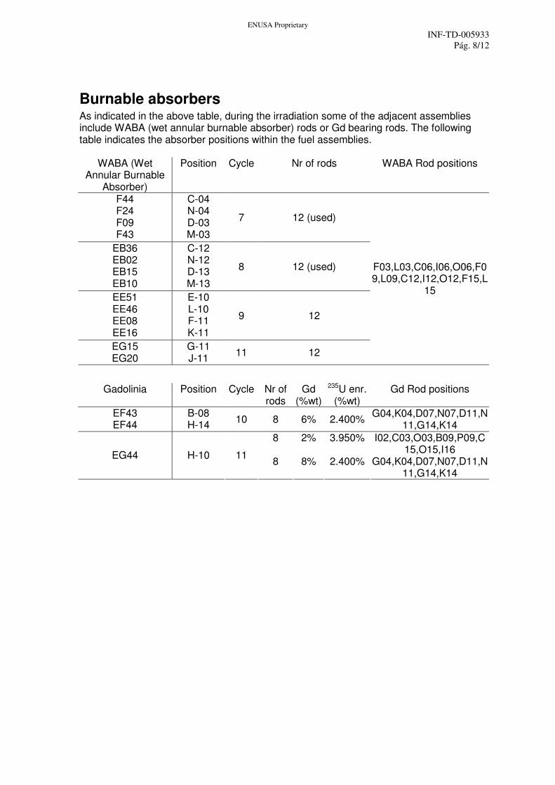
Burnable absorbers As indicated in the above table, during the irradiation some of the adjacent assemblies include WABA (wet annular burnable absorber) rods or Gd bearing rods. The following table indicates the absorber positions within the fuel assemblies.
WABA (Wet Annular Burnable
Absorber)
Position Cycle Nr of rods WABA Rod positions
F44 F24 F09 F43
C-04 N-04 D-03 M-03
7 12 (used)
EB36 EB02 EB15 EB10
C-12 N-12 D-13 M-13
8 12 (used)
EE51 EE46 EE08 EE16
E-10 L-10 F-11 K-11
9 12
EG15 EG20
G-11 J-11
11 12
F03,L03,C06,I06,O06,F09,L09,C12,I12,O12,F15,L
15
Gadolinia Position Cycle Nr of rods
Gd (%wt)
235U enr. (%wt)
Gd Rod positions
EF43 EF44
B-08 H-14
10 8 6% 2.400% G04,K04,D07,N07,D11,N
11,G14,K14
8 2% 3.950% I02,C03,O03,B09,P09,C15,O15,I16
EG44 H-10 11 8 8% 2.400% G04,K04,D07,N07,D11,N
11,G14,K14
ENUSA Proprietary
INF-TD-005933
Pág. 9/12
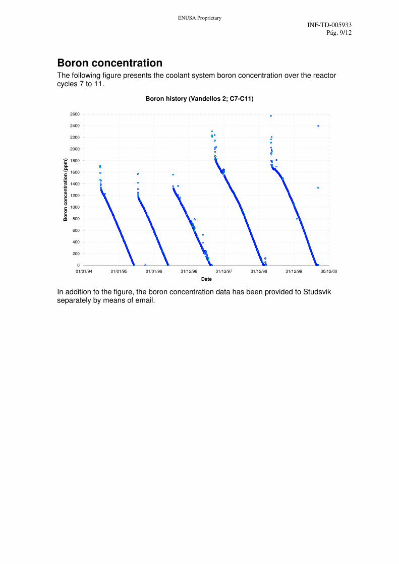
Boron concentration The following figure presents the coolant system boron concentration over the reactor cycles 7 to 11.
Boron history (Vandellos 2; C7-C11)
0
200
400
600
800
1000
1200
1400
1600
1800
2000
2200
2400
2600
01/01/94 01/01/95 01/01/96 31/12/96 31/12/97 31/12/98 31/12/99 30/12/00
Date
Bo
ron
co
ncen
trati
on
(p
pm
)
In addition to the figure, the boron concentration data has been provided to Studsvik separately by means of email.
ENUSA Proprietary
INF-TD-005933
Pág. 10/12
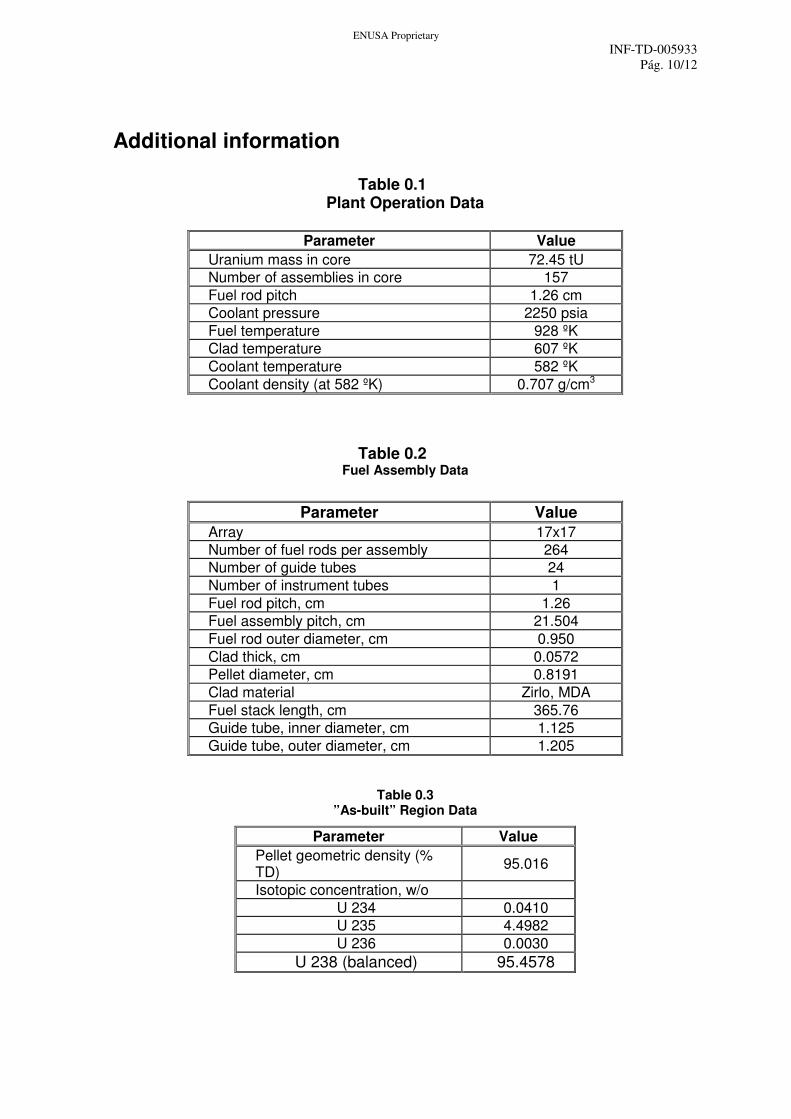
Additional information
Table 0.1 Plant Operation Data
Parameter Value
Uranium mass in core 72.45 tU
Number of assemblies in core 157
Fuel rod pitch 1.26 cm
Coolant pressure 2250 psia
Fuel temperature 928 ºK
Clad temperature 607 ºK
Coolant temperature 582 ºK
Coolant density (at 582 ºK) 0.707 g/cm3
Table 0.2 Fuel Assembly Data
Parameter Value
Array 17x17
Number of fuel rods per assembly 264
Number of guide tubes 24
Number of instrument tubes 1
Fuel rod pitch, cm 1.26
Fuel assembly pitch, cm 21.504
Fuel rod outer diameter, cm 0.950
Clad thick, cm 0.0572
Pellet diameter, cm 0.8191
Clad material Zirlo, MDA
Fuel stack length, cm 365.76
Guide tube, inner diameter, cm 1.125
Guide tube, outer diameter, cm 1.205
Table 0.3 ”As-built” Region Data
Parameter Value
Pellet geometric density (% TD)
95.016
Isotopic concentration, w/o
U 234 0.0410
U 235 4.4982
U 236 0.0030
U 238 (balanced) 95.4578
ENUSA Proprietary
INF-TD-005933
Pág. 11/12
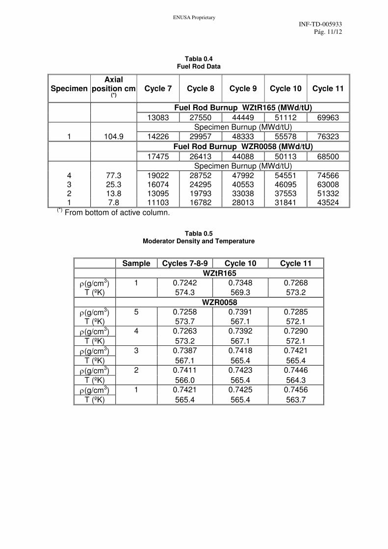
Tabla 0.4 Fuel Rod Data
Specimen Axial
position cm (*)
Cycle 7 Cycle 8 Cycle 9 Cycle 10 Cycle 11
Fuel Rod Burnup WZtR165 (MWd/tU)
13083 27550 44449 51112 69963
Specimen Burnup (MWd/tU)
1 104.9 14226 29957 48333 55578 76323
Fuel Rod Burnup WZR0058 (MWd/tU)
17475 26413 44088 50113 68500
Specimen Burnup (MWd/tU)
4 77.3 19022 28752 47992 54551 74566 3 25.3 16074 24295 40553 46095 63008 2 13.8 13095 19793 33038 37553 51332 1 7.8 11103 16782 28013 31841 43524
(*) From bottom of active column.
Tabla 0.5 Moderator Density and Temperature
Sample Cycles 7-8-9 Cycle 10 Cycle 11
WZtR165
ρ(g/cm3) 1 0.7242 0.7348 0.7268
T (ºK) 574.3 569.3 573.2
WZR0058
ρ(g/cm3) 5 0.7258 0.7391 0.7285
T (ºK) 573.7 567.1 572.1
ρ(g/cm3) 4 0.7263 0.7392 0.7290
T (ºK) 573.2 567.1 572.1
ρ(g/cm3) 3 0.7387 0.7418 0.7421
T (ºK) 567.1 565.4 565.4
ρ(g/cm3) 2 0.7411 0.7423 0.7446
T (ºK) 566.0 565.4 564.3
ρ(g/cm3) 1 0.7421 0.7425 0.7456
T (ºK) 565.4 565.4 563.7
ENUSA Proprietary
INF-TD-005933
Pág. 12/12
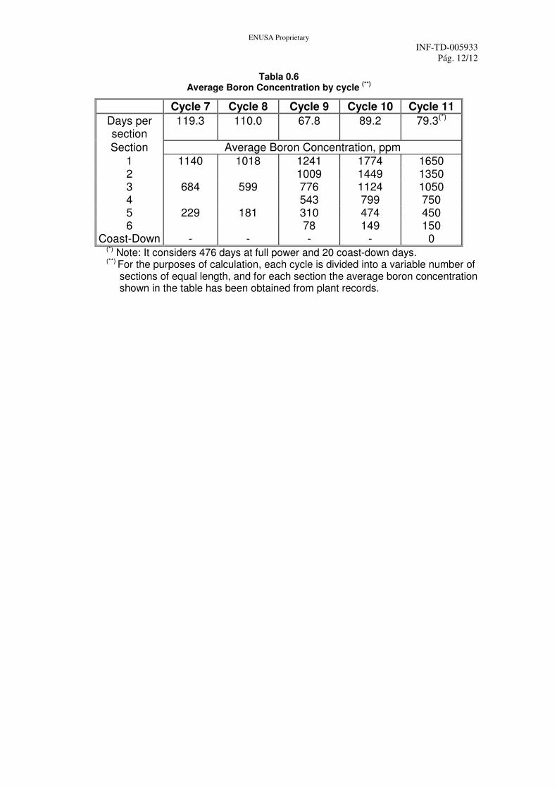
Tabla 0.6 Average Boron Concentration by cycle
(**)
Cycle 7 Cycle 8 Cycle 9 Cycle 10 Cycle 11
Days per section
119.3 110.0 67.8 89.2 79.3(*)
Section Average Boron Concentration, ppm
1 1140 1018 1241 1774 1650 2 1009 1449 1350 3 684 599 776 1124 1050 4 543 799 750 5 229 181 310 474 450 6 78 149 150
Coast-Down - - - - 0 (*) Note: It considers 476 days at full power and 20 coast-down days. (**) For the purposes of calculation, each cycle is divided into a variable number of
sections of equal length, and for each section the average boron concentration shown in the table has been obtained from plant records.


![Science Education Volume 66 Issue 1 1982 [Doi 10.1002%2Fsce.3730660113] Colin Gauld -- The Scientific Attitude and Science Education- A Critical Reappraisal](https://img.pdfslide.us/doc/110x75/577c813d1a28abe054ac0d82/science-education-volume-66-issue-1-1982-doi-1010022fsce3730660113-colin.jpg)