Embed Size (px)
Citation preview


Contents
1. Introduction ·································································································· 2
1.1 Research Project Changes and Challenges ·················································· 2
2. Developing the e-Navigation Course from the Model Course ·································· 3
2.1 Course Structure and Class Schedule ························································ 3
2.2 Lesson Planning ····················································································· 4
2.3 Week 1 ·································································································· 4
2.4 Week 2 ·································································································· 5
2.5 Week 3 ·································································································· 6
2.6 Week 4 ·································································································· 8
2.7 Week 5 ·································································································· 9
2.8 Week 6 ·································································································· 9
2.9 Week 7 ·································································································· 10
2.10 Week 8 ································································································· 11
2.11 Week 9 ································································································· 12
2.12 Week 10 ······························································································· 13
2.13 Week 11 ······························································································· 13
2.14 Course review and discussion ·································································· 13
3. Continued Development of the Head-Up Display Mockup ······································ 14
3.1 Equipment Setup (as reported in Phase 1) ·················································· 14
3.2 Conversion of the program from Adobe Air to C# ········································· 16
4. ARVCOP ····································································································· 17
4.1 Introduction to ARVCOP ·········································································· 17
4.2 Obtaining ARVCOP from TSI ··································································· 17
4.3 Testing ARVCOP on crewboat Ursa ··························································· 18
4.4 Testing ARVCOP in the simulator ····························································· 19
4.5 ARVCOP and HUD compared ··································································· 19
5. Preliminary Analysis of Data ············································································ 20
5.1 Surveys ································································································· 20
5.2 Survey Results ······················································································· 20
6. Presentation at 2011 e-Navigation Conference ···················································· 30
7. Conclusion and Notes on Further Research after Phase 2 ····································· 31
7.1 Final assessment of the Fall 2011 e-Navigation course ································· 31
(CMA) (CMA)

7.2 Future e-Navigation courses ····································································· 31
7.3 HUD Research Planned for 2012 ······························································· 32
8. Appendix······································································································ 34
8.1 e-Navigation course lecture presentations ·················································· 34
8.2 e-Navigation course lab instructions ·························································· 114
8.3 eNavigation Conference 2011 presentation ················································ 129
8.4 List of all sources used for the e-Navigation research project ························· 151
(CMA) (CMA)

e-Navigation Course Research and Development
(Phase II)
Captain Samuel R. Pecota, B.S., M.A., AFRIN, MNI
Associate Professor and Chair
Department of Marine Transportation
California Maritime Academy, [email protected]
Captain Scott Powell, B.S., M.S., MNI
Assistant Professor
Department of Marine Transportation
California Maritime Academy, [email protected]
Eric Holder, Ph.D.
Senior Scientist
Anacapa Sciences, Inc
Abstract: The International Maritime Organization has defined e-Navigation as the “. . .
integration, exchange, presentation and analysis of marine information . . .”[1] While this
definition has often been used, it is little understood from either an operational or functional
perspective. Moreover, there is little research being done to help understand the complexities of
the concept. A better understanding of the overall concept, and a more precisely defined set of
operational constructs would help to inform maritime educators and users alike. This lack of
understanding stems, in part, from the overly broad definition of e-Navigation, from the lack of
training standards that recognize the need to incorporate the new technology into bridge resource
management (BRM) techniques, and from the reliance on old, more traditional methods of
educating the mariner.
This project was conducted from September-December 2011 and had five primary research
objectives: 1) To use the e-Navigation model course developed in Phase I to create an actual e-
Navigation course that will become part of the Marine Transportation curriculum at Cal Maritime; 2)
to deliver this course to students on the summer training cruise of the Golden Bear in 2011; 3) to
determine the effectiveness of this course by measuring student performance and understanding of e-
Navigation concepts and techniques; 4) to continue to develop the HUD mock-up; and 5) to determine
the importance of marine HUDs and other prototype applications to the overall concept of e-
Navigation.
Keywords: e-Navigation, Head-Up Display, Full-Mission Simulator, ARVCOP
(CMA) (CMA)- 1 -
1. Introduction
This Final Report of Phase II of the e-Navigation Research and Development is a collaborative effort
of researchers Sam Pecota, Scott Powell and Eric Holder. One of the original members of Phase I of
the project, Steve Browne, was unable to participate in Phase II. David Coleman, another Cal
Maritime faculty member, assisted greatly in the administration of the course throughout the fall of
2011. Finally, Michael Noonan, Cal Maritime’s Director of Simulations, provided much-needed
technical expertise in the use of the advanced simulators and associated equipment used in the project.
1.1 Research Project Changes and Challenges
Phase II of the e-Navigation Research and Development Project, was faced with some unforeseen
challenges that occurred after the submission of the grant proposal. Originally, the e-Navigation
course component of the project was to be administered aboard the T.S. Golden Bear, Cal Maritime’s
152 meter training ship, during the summer cruise period from May to August 2011. A state-of-the-art
Navigation Laboratory, featuring among other things a Transas full mission simulator, was to be
utilized for the lab and research experiment portions of the e-Navigation course. Unfortunately, the
Transas simulation equipment, newly installed in April 2011, did not have sufficient time to go
through testing and de-bugging before the Golden Bear departed CMA on 1 May 2011. As a
consequence, the Navigation Laboratory equipment was not reliable enough to be used without severe
impact to the integrity of the e-Navigation course. Accordingly, the decision had to be made to
postpone the course offering until the Fall 2011 semester at which time either the Nav Lab equipment
might be satisfactorily operable or the course could be run in the Simulation Center on campus. The
latter choice was taken, as Transas could not immediately attend to their equipment aboard the Golden
Bear upon her return to Cal Maritime in late August. This change of venue for lab simulations in the
e-Navigation class did not have any significantly negative impact on the running of the course. It did
however reduce the time available for thorough data analysis from the end of the course to the
submission of this final report – only two weeks.
The second project modification involved the number of e-Navigation classes offered and student
population utilized. Originally, there were intended to be three simultaneously running e-Navigation
classes each being taught by a different instructor. However, there was great difficulty associated with
attracting enough students to fill the three classes, designed ideally for twenty-four students each. The
primary reason for this problem involved a controversy within the Cal Maritime Marine
Transportation Department over the granting of academic credit for the two previous offerings of
NAU395 e-Navigation in the Spring and Fall of 2010. Although the Academic Dean at the time,
Steve Kreta, suggested and supported the granting of academic credit for the course, several members
of the MT Department expressed strong objections to this policy. As a result, the new Academic Dean,
Steve Pronchick, reluctantly withdrew support for the granting of academic credit for the Fall 2011 e-
Navigation course. The direct consequence of this decision was extreme reluctance on the part of
students, particularly seniors and juniors, to add the course as a non-credit addition to their already
intensive course schedule. There simply were not enough students enrolled at the start of the semester
to run three classes. The twenty-one students who had signed up anyway were consolidated into one
class to be taught by Scott Powell on Wednesday evening. The other two classes were cancelled.
The third change to the project as originally proposed was of a decidedly more positive nature. The
researchers were offered use of an experimental 3-D navigational device known as ARVCOP
(Augmented Reality Visualization of the Common Operational Picture) for testing as part of the e-
Navigation course research component. Charles Benton, President of Technology Systems, Inc. of
Brunswick, ME, maker of ARVCOP, became acquainted with our research though a presentation
made by Eric Holder and Sam Pecota at the Royal Institute of Navigation’s NAV10 conference in
London, England on 2 December 2010. Mr. Benton suggested that we test one of his units (free of
charge) in the course and obtain student impressions of ARVCOP. We accepted his offer. Scott
(CMA) (CMA)- 2 -

Powell designed several lab sessions around the testing of ARVCOP both in the simulator and aboard
one of Cal Maritime’s small craft. We also compared the ARVCOP to our HUD mockup in
simulation experiments. The results were quite interesting and will be related later in this report. At
his request, Mr. Benton was provided access to the student survey data from the ARVCOP tests.
Lastly, the expected continued development of our Head-Up Display (HUD) program, Way Point Line
Drawer, did not occur as planned. The original programmer, Jim Hefner, changed jobs early in 2011
and was not able to devote time to write new code for the HUD. A prolonged search for a new
programmer did find one candidate, Evan McPeters, who began work on converting the program from
Adobe Air to the more widely used and more powerful C# language. Unfortunately, the complete
conversion did not occur in time to be tested as part of Phase II of this grant. Some of the research
time devoted to HUD development was therefore diverted into time required for the researchers to
obtain the ARVCOP program from TSI (which involved many phone calls, correspondence and
lengthy Go-to-Meeting sessions), learn how to use it, determine how to set it up both on the academy
crewboat and in the simulator, and run testing and troubleshooting on the device before using it in the
e-Navigation course. Nevertheless, Mr. McPeters has submitted a plan for the HUD program
conversion to C# and hoped to have a running version before the submission of this final report.
Details of this can be found in Section 3 below.
2. Developing the e-Navigation Course from the Model Course
2.1 Course Structure and Class Schedule
The course design, in keeping with the Model Course structure, called for a three-hour per week,
eleven-week course beginning in mid-September and finishing in mid-December 2011. This is
approximately the normal duration for the fall semester at Cal Maritime. The course was divided into
lecture and lab components. Wherever possible, the topics covered in the lecture were the same topics
examined during the lab simulations. The class was held once a week on Wednesday evening 1630-
2000 with a 30-minute break for dinner. Because the course was still classified as experimental
(assigned a NAU395 course number as a special topics class), students received 2 units of course
credit on a Credit/No Credit instead of graded basis. However, as stated earlier, 2 units were simply
added to the students’ transcript as an elective, not credited as units counting toward the Marine
Transportation major.
Date Lecture Lab
Week 1
9/14/11
Definition of e-Navigation Familiarization/introduction to IBEST
simulators
Week 2
9/21/11
e-Navigation details Exxon Valdez recreation
Week 3
9/28/11
BTM and BRM procedures Advanced Radar: Controlled Turns in
Pilotage
Week 4
10/5/11
ECDIS and GNSS Advanced ECDIS: AIS text messaging
HUD Introduction
Week 5
10/12/11
Radar and AIS Radar and AIS
Week 6
10/19/11
INS and IBS INS and IBS
Week 7
11/2/11
ARVCOP: Ursa ARVCOP: Ursa
Week 8
11/9/11
VTS and LRIT Mandatory/Advisory VTS
(CMA) (CMA)- 3 -
Week 9
11/16/11
GMDSS and e-Navigation ARVCOP exercise in FMB 3
Week 10
12/7/11
No lecture HUD exercise in FMB 3
Week 11
12/14/11
Class Survey No Lab
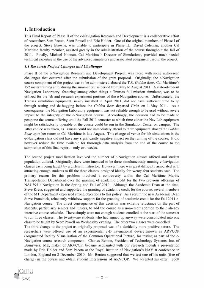
2.2 Lesson Planning
The NAU395 e-Navigation course is unique to Cal Maritime in that it allows for both cooperative and
collaborative learning between upper and lower class level students in a simulated navigation
environment. Cal Maritime’s Institutional Review Board (IRB) approval was sought and approved for
the application prior to the start of the course with the students completing Informed Consent Forms
and being provided a Participant’s Bill of Rights.
The first classes were primarily a familiarization with e-Navigation concepts and with the equipment
in the IBEST lab (part-task simulators) and full-mission simulator. Scenarios were created to match
the training background of the student population. Students with senior and junior class standing were
given the leadership role as the mate of each bridge team. Remaining students were predominately
freshman and so were given the followership role as helmsman and lookout. The final population of
the class was as follows:
Class standing Number
Senior 3
Junior 5
Sophomore 1
Freshman 8
Total enrolment 17
Table 1: Class enrolment
The original intent was for the class to be offered only to students with either senior or junior class
standing. But, there was insufficient enrolment leading up to the first class period due to the lack of
academic credit offered within the Marine Transportation curriculum (see Section 1.1 above). Prior to
the start of the semester the PI decided to offer the class to sophomore and freshman students who had
some maritime background. Initially, there was a total enrolment of twenty-one in the course. Four
students dropped by week three due to the academic responsibilities of their other classes.
The bridge teams for each exercise varied due to the number of participants and attendance. Since the
subject matter is so new and there are no available textbooks, many resources were provided via the
CMA online learning management system Moodle. References listed in each section were used to
help develop the particular topic area.
2.3 Week 1
Topic: Introduction to e-Navigation
This class involved the introduction of e-Navigation. Lecture material consisted of a PowerPoint
presentation, which followed the Model Course 1.XX Principles of Shipboard e-Navigation
requirements and introduced the topics and concepts that would be discussed throughout the semester.
(CMA) (CMA)- 4 -

In the lab section, students were provided a scenario on the Mississippi River at night using the e-
Navigation components of Radar/ARPA, ECDIS, and AIS. Each bridge team was given the task of
creating a safe route using the ECDIS from their initial position to a predetermined destination. This
scenario also allowed for some of the newer students to become familiar with the simulation
equipment in the IBEST lab.
Bridge teams: Watch Officer, Helmsman, and Lookout
Reading material provided: Lecture PowerPoint handouts (in handout form)
Reference(s):
[1] IALA e-Navigation Committee Frequently Asked Questions (Version 1.5 dated September 2010
[2] Patraiko, David, e-Navigation, Digital Ship, Presentation, The Nautical Institute, 2008
[3] Patraiko, David, Introducing the e-navigation revolution, The Nautical Institute, 2007
2.4 Week 2
Topic: The benefits of e-Navigation
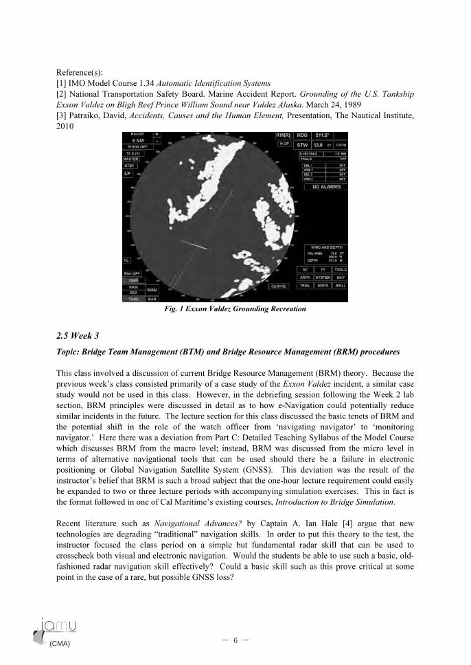
The lecture followed the content requirements of the Model Course. The main theme of this class
involved the recreation and discussion of the Exxon Valdez (1989) grounding incident using the
simulator in the IBEST lab projected on the SmartBoards [2]. This allowed for comparisons between
the visual channel and radar while the timeline and applicable Bridge Resource Management
perspectives were discussed (see figure 1). Prior to transitioning to the lab component of the class, a
briefing session was conducted with demonstrations of AIS messaging and Add Info Chart overlays
(to simulate AIS Application 1 Meteorological and Hydrological data in the form of Add Info) [1].
The incident was recreated and experienced both with and without the inclusion of current and future
electronic navigation technology. The students were allowed to take advantage of new concepts such
as AIS binary messages, which were then used to create Add Info chart overlays to represent no-go
areas of dense ice fields. A key difference between the actual event and this simulation is highlighted
in the dissemination of ice information. Instead of the view as shown in Fig. 1 below, where a ship
would see the ice only when it showed up on radar or provided by vessels that have previously
transited the area, this information could be provided by Vessel Traffic Service (VTS) with proper
surveillance sensors. Advanced ice reports with positional information could assist in the creation of
no-go areas that allow for route deviation within VTS and COLREGS Rule 10 requirements. These
routes could then be tested and checked to ensure that they are safe taking into consideration elements
such as under keel clearance and other hazards along the route that would yield alarms during the
route checking/passage planning phase. Since the IBEST lab has eight stations, the scenario was
intentionally designed to use only six of them, allowing one of the extra stations to be used for the
two-way transmission of AIS safety messages. This was accomplished through the inclusion of an
extra ownship, which was used in addition to the instructor station. This extra ownship was then used
essentially as VTS with AIS text messaging capabilities. It was within these capabilities that provision
was made for position information such as latitudes and longitudes that could then be sent and used by
the bridge teams to create the chart overlay/no-go areas. The Exxon Valdez grounding was used as a
case study to show students the benefits of modern marine navigation electronics utilizing e-
Navigation concepts compared with what was available in 1989.
Bridge team: 2 Watch Officers, Helmsman, and Lookout
Reading material provided: Lecture PowerPoint handouts (in electronic form)
(CMA) (CMA)- 5 -
Reference(s):
[1] IMO Model Course 1.34 Automatic Identification Systems
[2] National Transportation Safety Board. Marine Accident Report. Grounding of the U.S. Tankship
Exxon Valdez on Bligh Reef Prince William Sound near Valdez Alaska. March 24, 1989
[3] Patraiko, David, Accidents, Causes and the Human Element, Presentation, The Nautical Institute,
2010
Fig. 1 Exxon Valdez Grounding Recreation
2.5 Week 3
Topic: Bridge Team Management (BTM) and Bridge Resource Management (BRM) procedures
This class involved a discussion of current Bridge Resource Management (BRM) theory. Because the
previous week’s class consisted primarily of a case study of the Exxon Valdez incident, a similar case
study would not be used in this class. However, in the debriefing session following the Week 2 lab
section, BRM principles were discussed in detail as to how e-Navigation could potentially reduce
similar incidents in the future. The lecture section for this class discussed the basic tenets of BRM and
the potential shift in the role of the watch officer from ‘navigating navigator’ to ‘monitoring
navigator.’ Here there was a deviation from Part C: Detailed Teaching Syllabus of the Model Course
which discusses BRM from the macro level; instead, BRM was discussed from the micro level in
terms of alternative navigational tools that can be used should there be a failure in electronic
positioning or Global Navigation Satellite System (GNSS). This deviation was the result of the
instructor’s belief that BRM is such a broad subject that the one-hour lecture requirement could easily
be expanded to two or three lecture periods with accompanying simulation exercises. This in fact is
the format followed in one of Cal Maritime’s existing courses, Introduction to Bridge Simulation.
Recent literature such as Navigational Advances? by Captain A. Ian Hale [4] argue that new
technologies are degrading “traditional” navigation skills. In order to put this theory to the test, the
instructor focused the class period on a simple but fundamental radar skill that can be used to
crosscheck both visual and electronic navigation. Would the students be able to use such a basic, old-
fashioned radar navigation skill effectively? Could a basic skill such as this prove critical at some
point in the case of a rare, but possible GNSS loss?
(CMA) (CMA)- 6 -
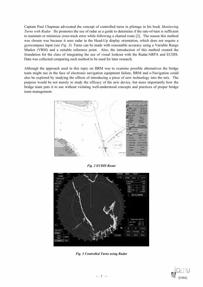
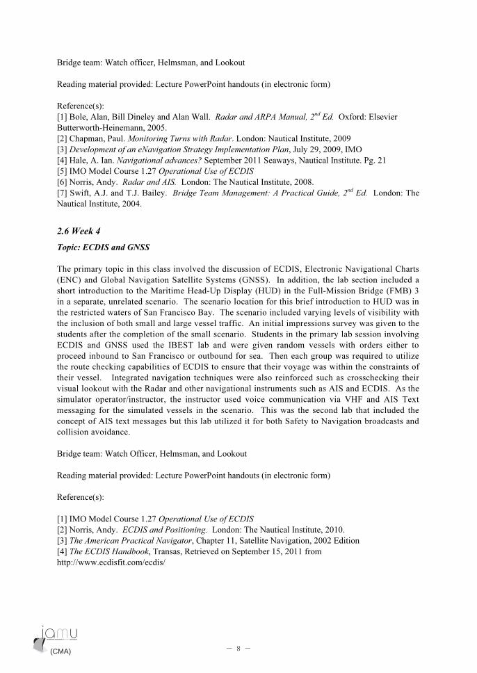
Captain Paul Chapman advocated the concept of controlled turns in pilotage in his book Monitoring
Turns with Radar. He promotes the use of radar as a guide to determine if the rate-of-turn is sufficient
to maintain or minimize cross-track error while following a charted route [2]. The reason this method
was chosen was because it uses radar in the Head-Up display orientation, which does not require a
gyrocompass input (see Fig. 3). Turns can be made with reasonable accuracy using a Variable Range
Marker (VRM) and a suitable reference point. Also, the introduction of this method created the
foundation for the class of integrating the use of visual lookout with the Radar/ARPA and ECDIS.
Data was collected comparing each method to be used for later research.
Although the approach used in this topic on BRM was to examine possible alternatives the bridge
team might use in the face of electronic navigation equipment failure, BRM and e-Navigation could
also be explored by studying the effects of introducing a piece of new technology into the mix. The
purpose would be not merely to study the efficacy of the new device, but more importantly how the
bridge team puts it to use without violating well-understood concepts and practices of proper bridge
team management.
Fig. 2 ECDIS Route
Fig. 3 Controlled Turns using Radar
(CMA) (CMA)- 7 -
Bridge team: Watch officer, Helmsman, and Lookout
Reading material provided: Lecture PowerPoint handouts (in electronic form)
Reference(s):
[1] Bole, Alan, Bill Dineley and Alan Wall. Radar and ARPA Manual, 2nd
Ed. Oxford: Elsevier
Butterworth-Heinemann, 2005.
[2] Chapman, Paul. Monitoring Turns with Radar. London: Nautical Institute, 2009
[3] Development of an eNavigation Strategy Implementation Plan, July 29, 2009, IMO
[4] Hale, A. Ian. Navigational advances? September 2011 Seaways, Nautical Institute. Pg. 21
[5] IMO Model Course 1.27 Operational Use of ECDIS
[6] Norris, Andy. Radar and AIS. London: The Nautical Institute, 2008.
[7] Swift, A.J. and T.J. Bailey. Bridge Team Management: A Practical Guide, 2nd
Ed. London: The
Nautical Institute, 2004.
2.6 Week 4
Topic: ECDIS and GNSS
The primary topic in this class involved the discussion of ECDIS, Electronic Navigational Charts
(ENC) and Global Navigation Satellite Systems (GNSS). In addition, the lab section included a
short introduction to the Maritime Head-Up Display (HUD) in the Full-Mission Bridge (FMB) 3
in a separate, unrelated scenario. The scenario location for this brief introduction to HUD was in
the restricted waters of San Francisco Bay. The scenario included varying levels of visibility with
the inclusion of both small and large vessel traffic. An initial impressions survey was given to the
students after the completion of the small scenario. Students in the primary lab session involving
ECDIS and GNSS used the IBEST lab and were given random vessels with orders either to
proceed inbound to San Francisco or outbound for sea. Then each group was required to utilize
the route checking capabilities of ECDIS to ensure that their voyage was within the constraints of
their vessel. Integrated navigation techniques were also reinforced such as crosschecking their
visual lookout with the Radar and other navigational instruments such as AIS and ECDIS. As the
simulator operator/instructor, the instructor used voice communication via VHF and AIS Text
messaging for the simulated vessels in the scenario. This was the second lab that included the
concept of AIS text messages but this lab utilized it for both Safety to Navigation broadcasts and
collision avoidance.
Bridge team: Watch Officer, Helmsman, and Lookout
Reading material provided: Lecture PowerPoint handouts (in electronic form)
Reference(s):
[1] IMO Model Course 1.27 Operational Use of ECDIS
[2] Norris, Andy. ECDIS and Positioning. London: The Nautical Institute, 2010.
[3] The American Practical Navigator, Chapter 11, Satellite Navigation, 2002 Edition
[4] The ECDIS Handbook, Transas, Retrieved on September 15, 2011 from
http://www.ecdisfit.com/ecdis/
(CMA) (CMA)- 8 -
2.7 Week 5
Topic: Radar and AIS
This class involved an introduction to New Technology (NT) Radar and AIS. The lecture section
consisted of a PowerPoint lecture and a YouTube video [2] on the Kelvin Hughes NT Radar. Also, a
presentation given by Captain Wayne Bailey [1] at the 2010 e-Navigation conference in Seattle was
reviewed and discussed. This particular presentation highlighted the limitations of AIS and some of
the errors in interpretation. The lab section involved a scenario where the bridge teams created routes
from the San Francisco sea buoy to Oakland. The scenario was created to run in restricted visibility
with greater reliance on AIS information. Each team was instructed to use the Radar/ARPA and
ECDIS integrated with AIS information to assist in their voyages. Distracter vessels were included to
determine if there was recognition of erroneous AIS data being transmitted. A questionnaire was
provided after the completion of the exercise to collect data on the different uses of AIS messages.
The intent of this collection was for further development of research topics in this area.
Bridge teams: Watch Officer, Helmsman, and Lookout
Reading material provided: Lecture PowerPoint handouts (in electronic form)
Reference(s):
[1] Bailey, Wayne. AIS: More than caller ID for vessels. Presentation. 2010 eNavigation Conference.
Seattle, WA
[2] IMO Model Course 1.34 Automatic Identification Systems
[3] SharpEye Solid-State Radar from Kelvin Hughes, YouTube video found at
http://www.youtube.com/watch?v=wgUaGNOseNQ
[4] USCG AIS website, 2011, http://www.navcen.uscg.gov/?pageName=AIS
2.8 Week 6
Topic: Integrated Navigation Systems (INS) and Integrated Navigation Bridges (INB)
This class involved a discussion about the development of the Integrated Navigation Bridges and their
place in e-Navigation. Key areas of the lecture discussion were the integration of sensors and the
challenges faced by watchstanders concerning overreliance on electronic navigation. The case study of the
Royal Majesty grounding was discussed with particular emphasis on sensor integration and the need to
cross-check the electronic navigation equipment on the bridge such as GNSS, Radar/ARPA and ECDIS [2].
In addition to the PowerPoint lecture given, an interactive presentation provided by Raytheon Anschutz
allowed for the class to have a virtual tour of a modern INB [3]. The lab section involved the introduction
of the Augmented Reality Visualization of the Common Operation Picture (ARVCOP) in the Full Mission
Bridge. Students were allowed to use the ARVCOP in a small route with varying levels of course changes
in a vessel with similar characteristics as the crew-boat Ursa, a small training vessel at CMA. The
students’ initial impressions of ARVCOP were uncertain, most likely because they were making mental
comparisons with the HUD, which was introduced to the class two weeks before (see Section 5 for detailed
results). In the IBEST lab, there was a comparison between the HUD and ECDIS-equipped groups in a
scenario located in the restricted waters of Puget Sound. Performance was measured between each of the
groups and surveys were used to collect data on perceptual observations.
Bridge teams: Watch Officer, Helmsman, and Lookout
Reading material provided: Lecture PowerPoint handouts (in electronic form)
(CMA) (CMA)- 9 -

Reference(s):
[1] IMO Model Course 1.32 Operational Use of Integrated Bridge Systems
[2] National Transportation Safety Board. Marine Accident Report. Grounding of the Panamanian
Passenger Vessel Royal Majesty on Rose and Crown Shoal near Nantucket, Massachusetts. June 10,
1995
[3] Next Generation of Integrated Navigation System. Raytheon-Anschutz. Presentation. Retrieved on
August 18, 2011 from http://www.raytheon-anchuetz.com/?id=266
2.9 Week 7
Topic: e-Navigation Research: ARVCOP
This class involved the use of the ARVCOP onboard the crew boat Ursa. A five-leg course route was
created with various course angles/changes to introduce the use of the ARVCOP in small boat
operations. The laptop with the ARVCOP software was mounted directly in line with the wheel and
centerline of the vessel (see Fig. 4). Therefore, each participant was able to maintain a visual lookout
and still be able to look down at the ARVCOP. Each student was afforded the opportunity to navigate
the vessel and then completed a survey to measure his or her perceptions of its use. There was great
student interest in this exercise, where for the first time students were able to use an augmented reality
3D perspective view navigation device in a real, not simulated, environment. Unfortunately, a second
edition of the class scheduled for the next week had to be cancelled due to safety considerations
involved in running the exercise without adequate daylight. Nevertheless, even after only one run
using ARVCOP on the crewboat, many participants commented that they felt that they had more
control over the real vessel than they ever had in the simulator.
Bridge teams: Watch Officer (Helmsman)
Fig. 4 ARVCOP aboard the Ursa
(CMA) (CMA)- 10 -
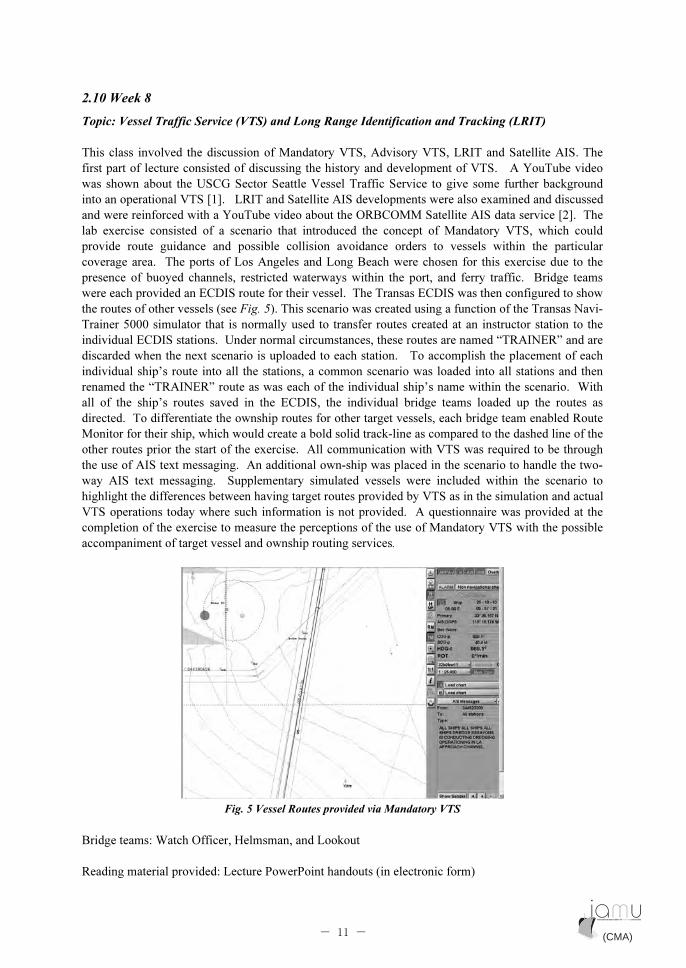
2.10 Week 8
Topic: Vessel Traffic Service (VTS) and Long Range Identification and Tracking (LRIT)
This class involved the discussion of Mandatory VTS, Advisory VTS, LRIT and Satellite AIS. The
first part of lecture consisted of discussing the history and development of VTS. A YouTube video
was shown about the USCG Sector Seattle Vessel Traffic Service to give some further background
into an operational VTS [1]. LRIT and Satellite AIS developments were also examined and discussed
and were reinforced with a YouTube video about the ORBCOMM Satellite AIS data service [2]. The
lab exercise consisted of a scenario that introduced the concept of Mandatory VTS, which could
provide route guidance and possible collision avoidance orders to vessels within the particular
coverage area. The ports of Los Angeles and Long Beach were chosen for this exercise due to the
presence of buoyed channels, restricted waterways within the port, and ferry traffic. Bridge teams
were each provided an ECDIS route for their vessel. The Transas ECDIS was then configured to show
the routes of other vessels (see Fig. 5). This scenario was created using a function of the Transas Navi-
Trainer 5000 simulator that is normally used to transfer routes created at an instructor station to the
individual ECDIS stations. Under normal circumstances, these routes are named “TRAINER” and are
discarded when the next scenario is uploaded to each station. To accomplish the placement of each
individual ship’s route into all the stations, a common scenario was loaded into all stations and then
renamed the “TRAINER” route as was each of the individual ship’s name within the scenario. With
all of the ship’s routes saved in the ECDIS, the individual bridge teams loaded up the routes as
directed. To differentiate the ownship routes for other target vessels, each bridge team enabled Route
Monitor for their ship, which would create a bold solid track-line as compared to the dashed line of the
other routes prior the start of the exercise. All communication with VTS was required to be through
the use of AIS text messaging. An additional own-ship was placed in the scenario to handle the two-
way AIS text messaging. Supplementary simulated vessels were included within the scenario to
highlight the differences between having target routes provided by VTS as in the simulation and actual
VTS operations today where such information is not provided. A questionnaire was provided at the
completion of the exercise to measure the perceptions of the use of Mandatory VTS with the possible
accompaniment of target vessel and ownship routing services.
Fig. 5 Vessel Routes provided via Mandatory VTS
Bridge teams: Watch Officer, Helmsman, and Lookout
Reading material provided: Lecture PowerPoint handouts (in electronic form)
(CMA) (CMA)- 11 -
Reference(s):
[1] 2004 USCG Sector Seattle Vessel Traffic Service. USCG. Video. Retrieved on September 7, 2011
from http://www.youtube.com/watch?v=Fs2fUCzi6h4.
[2] ORBCOMM Satellite AIS Data Service Video. ORBCOMMAIS. Retrieved on September 7, 2011
from http://www.youtube.com/watch?v=MQDd5xr-jdk
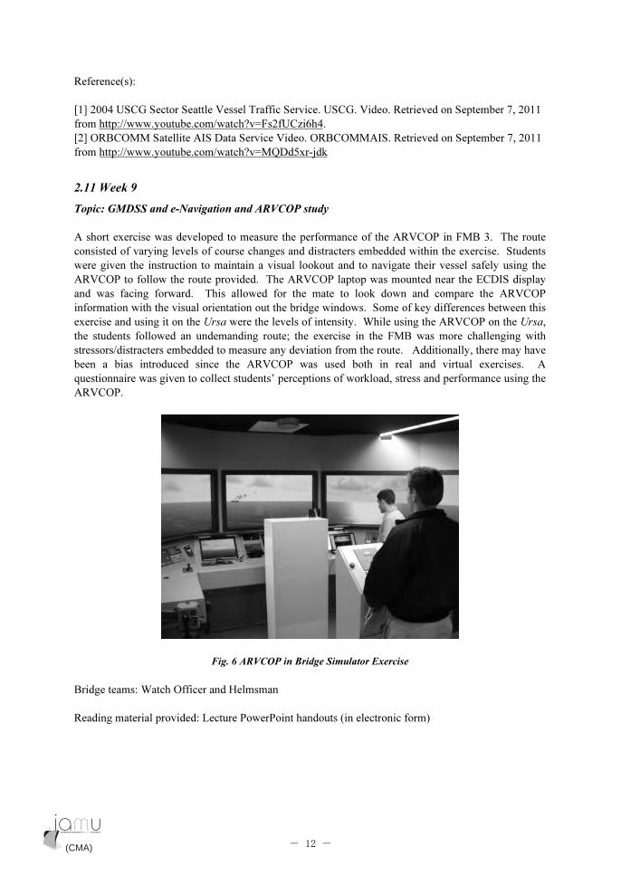
2.11 Week 9
Topic: GMDSS and e-Navigation and ARVCOP study
A short exercise was developed to measure the performance of the ARVCOP in FMB 3. The route
consisted of varying levels of course changes and distracters embedded within the exercise. Students
were given the instruction to maintain a visual lookout and to navigate their vessel safely using the
ARVCOP to follow the route provided. The ARVCOP laptop was mounted near the ECDIS display
and was facing forward. This allowed for the mate to look down and compare the ARVCOP
information with the visual orientation out the bridge windows. Some of key differences between this
exercise and using it on the Ursa were the levels of intensity. While using the ARVCOP on the Ursa,
the students followed an undemanding route; the exercise in the FMB was more challenging with
stressors/distracters embedded to measure any deviation from the route. Additionally, there may have
been a bias introduced since the ARVCOP was used both in real and virtual exercises. A
questionnaire was given to collect students’ perceptions of workload, stress and performance using the
ARVCOP.
Fig. 6 ARVCOP in Bridge Simulator Exercise
Bridge teams: Watch Officer and Helmsman
Reading material provided: Lecture PowerPoint handouts (in electronic form)
(CMA) (CMA)- 12 -
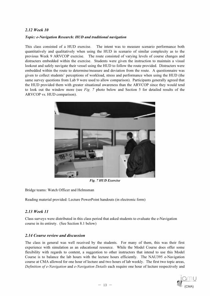
2.12 Week 10
Topic: e-Navigation Research: HUD and traditional navigation
This class consisted of a HUD exercise. The intent was to measure scenario performance both
quantitatively and qualitatively when using the HUD in scenario of similar complexity as to the
previous Week 9 ARVCOP exercise. The route consisted of varying levels of course changes and
distracters embedded within the exercise. Students were given the instruction to maintain a visual
lookout and safely navigate their vessel using the HUD to follow the route provided. Distracters were
embedded within the route to determine/measure and deviation from the route. A questionnaire was
given to collect students’ perceptions of workload, stress and performance when using the HUD (the
same survey questions from Lab 9 were used to allow comparison). Participants generally agreed that
the HUD provided them with greater situational awareness than the ARVCOP since they would tend
to look out the window more (see Fig. 7 photo below and Section 5 for detailed results of the
ARVCOP vs. HUD comparison).
Fig. 7 HUD Exercise
Bridge teams: Watch Officer and Helmsman
Reading material provided: Lecture PowerPoint handouts (in electronic form)
2.13 Week 11
Class surveys were distributed in this class period that asked students to evaluate the e-Navigation
course in its entirety. (See Section 8.1 below)
2.14 Course review and discussion
The class in general was well received by the students. For many of them, this was their first
experience with simulation as an educational resource. While the Model Course does offer some
flexibility with regards to content, a suggestion to other instructors that intend to use this Model
Course is to balance the lab hours with the lecture hours efficiently. The NAU395 e-Navigation
course at CMA allowed for one hour of lecture and two hours of lab weekly. The first two topic areas,
Definition of e-Navigation and e-Navigation Details each require one hour of lecture respectively and
(CMA) (CMA)- 13 -

no simulation exercise. The fourth topic, ECDIS and GNSS, suggests one hour of lecture and five
hours of simulation exercises. With this academic schedule and following the Model Course, the
lectures would soon creep out of step with the simulation exercise(s). A challenge with the course
was not being able to use more advanced navigational methods due to the student population. While
the overall content was covered and allowed for both collaborative and cooperative learning, if the
student population was more homogenous in regards to class standing such as a balance between
seniors and juniors, more advance topics could be covered and at a more rapid pace. The challenge
was evident with the varying levels of attendance, which had some impact on how many bridges could
be run at any given time in the simulation exercises. Perhaps if this class were given as credit within
an academic program, attendance would be less of a problem. Additionally, if this class had been
offered for credit, it could have allowed for greater participation by both senior and junior cadets.
Notwithstanding the lack of credit given for the course, attendance was normally higher for the
freshman cadets who welcomed the opportunity to use the simulation equipment
The IMO has defined e-Navigation to be “…the harmonized collection, integration, exchange,
presentation and analysis of marine information onboard and ashore by electronic means to enhance
berth to berth navigation and related services for safety and security at sea and protection of the
marine environment.” The Fall 2011 e-Navigation course was designed and developed with this
definition in mind. The simulation exercises were structured to take advantage of the bridge resources
available to each team at the time. Truly, looking out the window or at an ECDIS or radar screen is
only effective if you have an appreciation for what you are seeing. Accordingly, each exercise pre-
brief included a demonstration of key learning objectives and a refresher of bridge equipment
operation. New navigational technologies and procedures, especially those pertinent to e-Navigation,
were discussed in the exercise debrief.
A properly constructed course in e-Navigation, as with any modern course in marine navigation,
should both teach and promote navigation practice in an integrated manner. The Simulation Center at
Cal Maritime promotes this type of integrated navigation approach. This class offered the opportunity
to use the Transas Navi-Trainer 4000/5000 simulator in an integrated fashion as opposed to other
courses such as Radar/ARPA and ECDIS, which are taught presently as stand-alone courses. This
class also allowed for greater creativity in scenario construction than is possible in the existing Cal
Maritime bridge simulation courses, demonstrating such novelties as VTS communications with AIS
text messaging and the display of target vessel routes on ECDIS. Advanced topics such as Controlled
Turns in Pilotage and AIS text messaging can be used within realistic scenarios that impress upon the
student the need to utilize all navigation and communications equipment in a harmonious and effective
manner.
3. Continued Development of the Head-Up Display Mockup
3.1 Equipment Setup (as reported in Phase I)
The operating program used originally for the HUD mockup was written in Adobe Air, using the Flex
3 Builder Platform. Screenshots of the Graphical User Interface (GUI) and the Augmented Reality
Display screen appear below.
- 14 -(CMA) (CMA)

Fig. 8 HUD Administrative Interface
Fig. 9 HUD Augmented Reality Projection
The equipment setup for the HUD mockup used in the simulators is presented in the diagram below.
(CMA) (CMA)- 15 -

Fig. 10 HUD Mockup Setup in Simulator
The (4) projectors used were type Optoma PK301. Each projector was connected to the Dell laptop
computer via VGA connection. Also connected to the laptop was a SeaLINK +4 DB9 Serial Interface
Adapter that translated the simulated AIS data output from the Transas simulator running NT Pro 5000
software. A standard null modem cable connected the serial adapter to one of the simulator computers
driving the radar display.
This setup was unchanged from that used in the last e-Navigation course in the Fall of 2010.
3.2 Conversion of the program from Adobe Air to C#
Notes from new HUD programmer Evan McPeters:
The Flex 3 Builder platform using the Sandy 3D plug-in for 3-dimensional drawing was used for
initial HUD prototype development. Recently, it became clear that Flex Builder platform was not
adequate for developing an accurate simulation of fast moving vessels mostly due to its limited screen
refresh rate capabilities. As well, Adobe Flash files, those outputted by Flex Builder, are not industry
standard for simulation programming and could as such hinder further progress in developing a
working system.
Redeveloping the system with Microsoft’s C# platform would support using Microsoft XNA for
graphics rendering. C# is an industry and military standard programming environment, which, along
with XNA will provide ample processing power for simulations of even the fastest moving and most
data intensive vessel systems.
Work has already begun on the conversion of the original prototype into the more robust C# language.
The following items will be completed by December 30, 2011:
• An overall project structure will be built
• Initial 3-dimensional data structures will be created
• Initial data translation algorithms will be completed
(CMA) (CMA)- 16 -
• Initial data conversion algorithms will be configured to place some 3d objects at grid
coordinates
Monthly progress reports will be made as work continues into 2012.
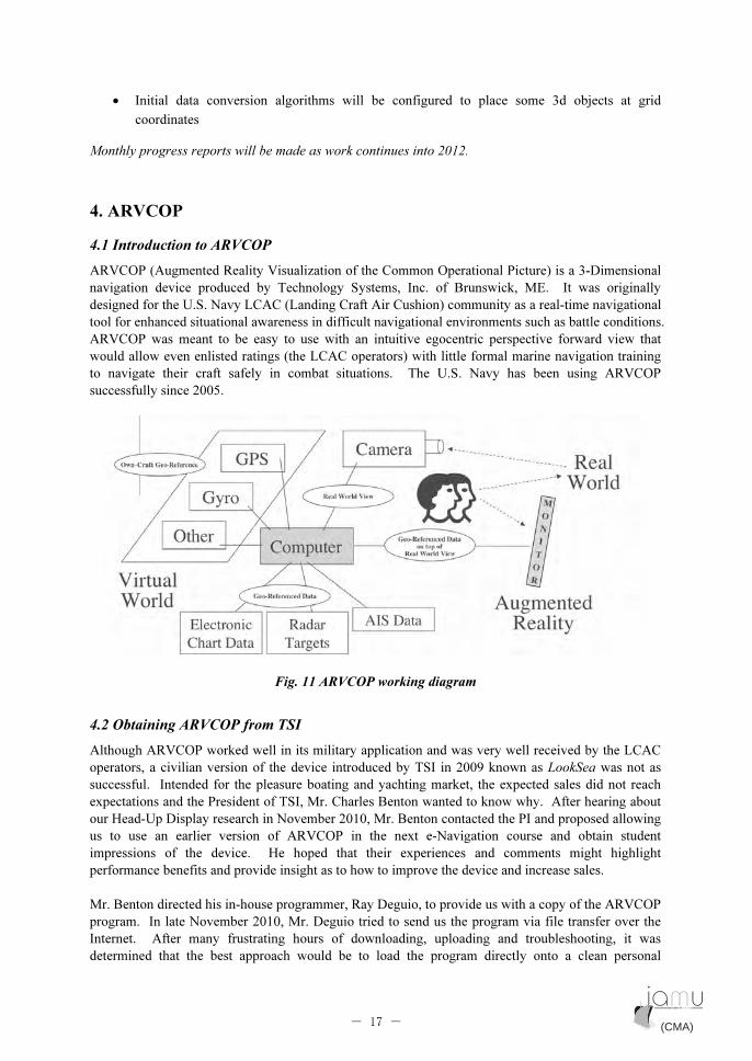
4. ARVCOP
4.1 Introduction to ARVCOP
ARVCOP (Augmented Reality Visualization of the Common Operational Picture) is a 3-Dimensional
navigation device produced by Technology Systems, Inc. of Brunswick, ME. It was originally
designed for the U.S. Navy LCAC (Landing Craft Air Cushion) community as a real-time navigational
tool for enhanced situational awareness in difficult navigational environments such as battle conditions.
ARVCOP was meant to be easy to use with an intuitive egocentric perspective forward view that
would allow even enlisted ratings (the LCAC operators) with little formal marine navigation training
to navigate their craft safely in combat situations. The U.S. Navy has been using ARVCOP
successfully since 2005.
Fig. 11 ARVCOP working diagram
4.2 Obtaining ARVCOP from TSI
Although ARVCOP worked well in its military application and was very well received by the LCAC
operators, a civilian version of the device introduced by TSI in 2009 known as LookSea was not as
successful. Intended for the pleasure boating and yachting market, the expected sales did not reach
expectations and the President of TSI, Mr. Charles Benton wanted to know why. After hearing about
our Head-Up Display research in November 2010, Mr. Benton contacted the PI and proposed allowing
us to use an earlier version of ARVCOP in the next e-Navigation course and obtain student
impressions of the device. He hoped that their experiences and comments might highlight
performance benefits and provide insight as to how to improve the device and increase sales.
Mr. Benton directed his in-house programmer, Ray Deguio, to provide us with a copy of the ARVCOP
program. In late November 2010, Mr. Deguio tried to send us the program via file transfer over the
Internet. After many frustrating hours of downloading, uploading and troubleshooting, it was
determined that the best approach would be to load the program directly onto a clean personal
(CMA) (CMA)- 17 -
computer in Maine. Accordingly, the PI mailed a new PC to TSI in September 2011. This computer
was purchased and the shipping paid for by the PI at personal expense since there is no provision in
the IAMU grant for the purchase of equipment. The PI also purchased a special dongle from the
Jeppesen Company in Norway in order to access the C-MAP charts that are part of the ARVCOP
database. These purchases had to be made if ARVCOP were to be included as part of the e-
Navigation class. The PI does not expect to be reimbursed for them.
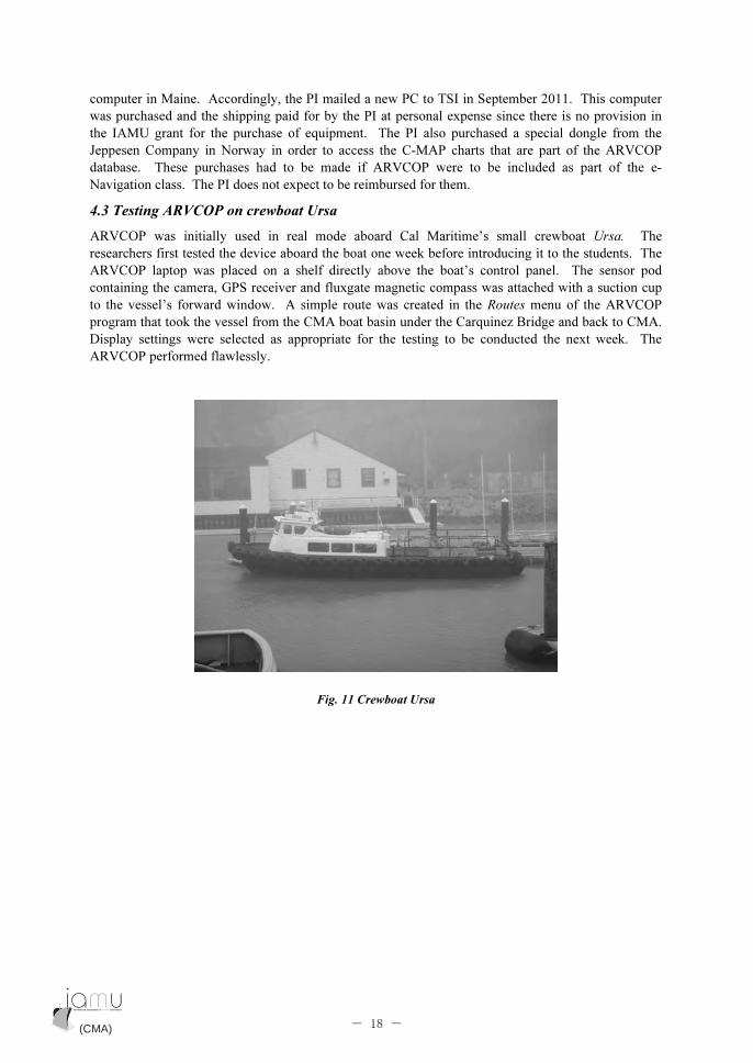
4.3 Testing ARVCOP on crewboat Ursa
ARVCOP was initially used in real mode aboard Cal Maritime’s small crewboat Ursa. The
researchers first tested the device aboard the boat one week before introducing it to the students. The
ARVCOP laptop was placed on a shelf directly above the boat’s control panel. The sensor pod
containing the camera, GPS receiver and fluxgate magnetic compass was attached with a suction cup
to the vessel’s forward window. A simple route was created in the Routes menu of the ARVCOP
program that took the vessel from the CMA boat basin under the Carquinez Bridge and back to CMA.
Display settings were selected as appropriate for the testing to be conducted the next week. The
ARVCOP performed flawlessly.
Fig. 11 Crewboat Ursa
(CMA) (CMA)- 18 -

Fig. 12 ARVCOP display
The actual testing of ARVCOP with student participants is described in Section 2.9 above and the
results of the corresponding survey in Section 5.2 below.
4.4 Testing ARVCOP in the simulator
Two weeks after testing aboard the crewboat, ARVCOP was brought into the full mission simulator.
The equipment setup was similar to that used for the HUD with this notable exception: instead of the
Augmented Reality (AR) image being projected onto the forward plasma screen (visual channel) in the
simulator as with the HUD, the ARVCOP camera was directed at the plasma screen and its image
displayed on the ARVCOP laptop computer screen which was superimposed with AR images. Herein
lies the fundamental difference between HUD and ARVCOP, two otherwise seemingly similar devices.
The photos of the students conning the vessels in Fig. 6 and 7 in Section 2 say it all; one has his head
up, the other down.
4.5 ARVCOP and HUD compared
A full discussion of the qualitative differences, perceptions and preferences of the students for HUD vs.
ARVCOP are related below in Section 5. Briefly stated though, the predominant difference between
the two devices involved the perceived effect each had on the navigator’s level of Situational
Awareness (SA). Unfortunately due to the lack of time between the end of the e-Navigation course
and the grant report deadline, objective, quantitative data analysis of student performance using
ARVCOP and HUD could not be completed. It is hoped that this information can be presented to the
IAMU community next year at AGA13 in St. John’s, Newfoundland. Whether or not the quantitative
data of student performance during the labs confirm the perceived superiority of HUD, the general
consensus of the students was that HUD should be preferred over ARVCOP mainly for the greater
level of SA it promoted through increased head up and eyes out the window time. One other
interesting, though anecdotal, observation by the PI was that the students seemed to have an easier
time staying on track using ARVCOP in the real environment on the crewboat than in the simulator.
The tasks were very similar in degree of difficulty and yet they seemed to wander off the trackline
much more in the simulator. The reasons for this may have something to do with better SA due to the
greater variety of sensory inputs (sound, vibration, motion) that the real boat provides that are
unavailable in the simulator. In any event, more research on this point needs to be done especially
after a real-world maritime HUD prototype is ready for testing.
(CMA) (CMA)- 19 -
5. Preliminary Analysis of Data
5.1 Surveys
Many lab sessions required students to fill out pre-simulation and/or post-simulation surveys. These
contained questions and answers in standard survey formats, such as Likert, semantic differential, and
other appropriate formats for rating, comparison and quantification. Any lab session that utilized the
HUD mockup or ARVCOP had one or more surveys associated with it. Our research partner Dr. Eric
Holder, a human factors specialist, wrote the surveys that concerned student perceptions of the HUD
or ARVCOP. The principal investigator and course instructor drew up other surveys on student
perceptions of their navigational performance. Preliminary survey results and selected student
comments are discussed below.
5.2 Survey Results
5.2.1 Lab 4 This lab section included the introduction of the Maritime Head-Up Display (HUD) in the
Full-Mission Bridge (FMB) 3. The scenario location for this brief introduction was in the restricted
waters of San Francisco Bay. The scenario included varying levels of visibility with the inclusion of
both small and large vessel traffic. After completing a small introduction scenario students completed
an initial impression survey. The survey included the fourteen items (listed below) with space for
commentary.
Each item was presented on a 1-5 Likert scale with 1-5 representing Strongly Disagree, Disagree,
Neutral, Agree, and Strongly Agree respectively. The t-tests performed compared the group mean to
the neutral value of 3 with a null hypothesis that participants’ opinions were neutral. The significance
criterion was set at p < .0071 and any finding with a p ≤ .0071 or less was considered significant1
. A
significant finding with a positive t-value would indicate significant agreement with an item and a
significant finding with a negative t-value would indicate significant disagreement with an item. The
results are presented below along with a summary of relevant comments for each item and conclusions
at the end.
Item 1: The HUD would be very useful in piloting situations.
Mean T-value df P SE Range
4.27 5.369 10 < .001* .237 3-5
This result was significant. Participants felt that the HUD would be very useful in piloting situations.
One participant noted that the projected lines on the screen help but another cautioned that the quality
of the lines and perspective impacted their trust of the system. Advancements, such as contact
information, chart NavAids, and other pertinent information, would be seen to increase the utility for
one participant. Piloting was listed several times in the general comments as an applicable situation
and benefit for HUD. One participant summarized the benefit saying that HUD combines our radar
and ECIDS information with the necessary visual confirmation. The more certainty, the less stress.
One participant noted that pilotage was not a good situation for HUD as HUD does not change mode
for water depth and in port complications.
Item 2: The HUD would be very useful in docking situations.
1
The overall significance criterion was set a p <.10, rather than the standard .05, to reduce Type 2 error potential
but also represent an acceptable and still Type 1 Error conservative value for an exploratory study. The
Bonferroni Correction was then applied based on the number of tests (14), resulting in the value listed above of p
< .0071 (.10 divided by 14). Significant items are marked with a *
(CMA) (CMA)- 20 -
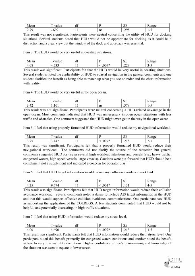
Mean T-value df P SE Range
2.79 -.699 11 ns .298 1-5
This result was not significant. Participants were neutral concerning the utility of HUD for docking
situations. Several students noted that HUD would not be appropriate for docking as it could be a
distraction and a clear view out the window of the dock and approach was essential.
Item 3: The HUD would be very useful in coasting situations.
Mean T-value df P SE Range
4.08 4.733 11 < .007* .229 3-5
This result was significant. Participants felt that the HUD would be very useful in coasting situations.
Several students noted the applicability of HUD to coastal navigation in the general comments and one
student clarified the benefit as being able to match up what you see on radar and the chart information
with reality.
Item 4: The HUD would be very useful in the open ocean.
Mean T-value df P SE Range
3.42 1.101 11 ns .379 1-5
This result was not significant. Participants were neutral concerning a HUD-related advantage in the
open ocean. Most comments indicated that HUD was unnecessary in open ocean situations with less
traffic and obstacles. One comment suggested that HUD might even get in the way in the open ocean.
Item 5: I feel that using properly formatted HUD information would reduce my navigational workload.
Mean T-value df P SE Range
3.75 3.447 11 < .007* .218 2-5
This result was significant. Participants felt that a properly formatted HUD would reduce their
navigational workload. The comments did not clarify the source of the reduction but general
comments suggested HUD for use in several high workload situations and vessels (e.g., heavy traffic,
congested waters, high speed vessels, large vessels). Cautions were put forward that HUD should be a
compliment not a supplement and indicated a concern for operator bias.
Item 6: I feel that HUD target information would reduce my collision avoidance workload.
Mean T-value df P SE Range
4.25 9.574 11 < .001* .131 4-5
This result was significant. Participants felt that HUD target information would reduce their collision
avoidance workload. Several comments noted a desire to include AIS target information in the HUD
and that this would support effective collision avoidance communications. One participant saw HUD
as supporting the application of the COLREGS. A few students commented that HUD would not be
helpful, and potentially distracting, in high traffic situations.
Item 7: I feel that using HUD information would reduce my stress level.
Mean T-value df P SE Range
4.00 4.690 11 < .007* .213 3-5
This result was significant. Participants felt that HUD information would reduce their stress level. One
participant noted this benefit primarily for congested waters conditions and another noted the benefit
in low to very low visibility conditions. Higher confidence in one’s manoeuvring and knowledge of
the situation was seen to equate to lower stress.
(CMA) (CMA)- 21 -
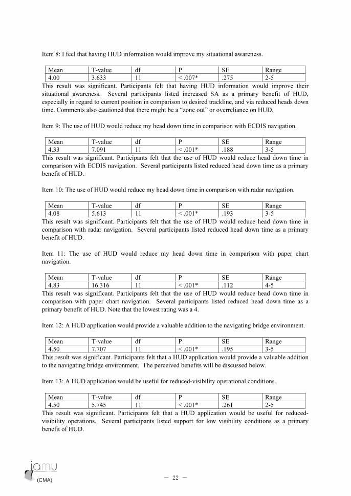
Item 8: I feel that having HUD information would improve my situational awareness.
Mean T-value df P SE Range
4.00 3.633 11 < .007* .275 2-5
This result was significant. Participants felt that having HUD information would improve their
situational awareness. Several participants listed increased SA as a primary benefit of HUD,
especially in regard to current position in comparison to desired trackline, and via reduced heads down
time. Comments also cautioned that there might be a “zone out” or overreliance on HUD.
Item 9: The use of HUD would reduce my head down time in comparison with ECDIS navigation.
Mean T-value df P SE Range
4.33 7.091 11 < .001* .188 3-5
This result was significant. Participants felt that the use of HUD would reduce head down time in
comparison with ECDIS navigation. Several participants listed reduced head down time as a primary
benefit of HUD.
Item 10: The use of HUD would reduce my head down time in comparison with radar navigation.
Mean T-value df P SE Range
4.08 5.613 11 < .001* .193 3-5
This result was significant. Participants felt that the use of HUD would reduce head down time in
comparison with radar navigation. Several participants listed reduced head down time as a primary
benefit of HUD.
Item 11: The use of HUD would reduce my head down time in comparison with paper chart
navigation.
Mean T-value df P SE Range
4.83 16.316 11 < .001* .112 4-5
This result was significant. Participants felt that the use of HUD would reduce head down time in
comparison with paper chart navigation. Several participants listed reduced head down time as a
primary benefit of HUD. Note that the lowest rating was a 4.
Item 12: A HUD application would provide a valuable addition to the navigating bridge environment.
Mean T-value df P SE Range
4.50 7.707 11 < .001* .195 3-5
This result was significant. Participants felt that a HUD application would provide a valuable addition
to the navigating bridge environment. The perceived benefits will be discussed below.
Item 13: A HUD application would be useful for reduced-visibility operational conditions.
Mean T-value df P SE Range
4.50 5.745 11 < .001* .261 2-5
This result was significant. Participants felt that a HUD application would be useful for reduced-
visibility operations. Several participants listed support for low visibility conditions as a primary
benefit of HUD.
(CMA) (CMA)- 22 -
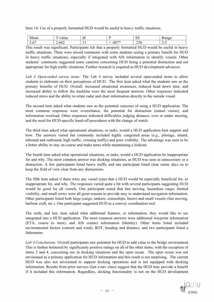
Item 14: Use of a properly formatted HUD would be useful in heavy traffic situations.
Mean T-value df P SE Range
3.67 2.602 11 < .007* .256 2-5
This result was significant. Participants felt that a properly formatted HUD would be useful in heavy
traffic situations. There were mixed comments with some students seeing a primary benefit for HUD
in heavy traffic situations, especially if integrated with AIS information to identify vessels. Other
students’ comments suggested some cautions concerning HUD being a potential distraction and not
appropriate for high traffic situations. Further research is required as HUD development advances.
Lab 4 Open-ended survey items: The Lab 4 survey included several open-ended items to allow
students to elaborate on their perceptions of HUD. The first item asked what the students saw as the
primary benefits of HUD. Overall, increased situational awareness, reduced head down time, and
increased ability to follow the trackline were the most frequent answers. Other responses indicated
reduced stress and the ability to relate radar and chart information directly to the outside visual.
The second item asked what students saw as the potential concerns of using a HUD application. The
most common responses were overreliance, the potential for distraction (tunnel vision), and
information overload. Other responses indicated difficulties judging distance, over or under steering,
and the need for HUD-specific hand-off procedures with the change of watch.
The third item asked what operational situations, or tasks, would a HUD application best support and
how. The answers varied but commonly included highly congested areas (e.g., pilotage, inland,
inbound and outbound, high traffic, crossing traffic) and poor visibility. The advantage was seen to be
a better ability to stay on course and make turns while maintaining a lookout.
The fourth item asked what operational situations, or tasks, would a HUD application be inappropriate
for and why. The most common answer was docking situations, as HUD was seen as unnecessary or a
distraction. A few participants listed heavy traffic and one participant listed clear sunny days so to
keep the field of view clear from any distractions.
The fifth item asked if there were any vessel types that a HUD would be especially beneficial for, or
inappropriate for, and why. The responses varied quite a bit with several participants suggesting HUD
would be good for all vessels. One participant noted that fast moving, hazardous cargo, limited
visibility, and small crews were all great reasons to provide easy to understand navigation information.
Other participants listed both large (cargo, tankers, cruiseships, liners) and small vessels (fast moving,
harbour craft, etc.). One participant suggested HUD as a convoy coordination tool.
The sixth, and last, item asked what additional features, or information, they would like to see
integrated into a HUD application. The most common answers were additional waypoint information
(ETA, course to steer), and AIS contact information (Identity). Other items listed included
environmental factors (current and wind), ROT, heading and distance, and two participants listed a
fathometer.
Lab 4 Conclusions: Overall participants saw potential for HUD to add value to the bridge environment.
This is further bolstered by significantly positive ratings on all of the other items, with the exception of
items 2 and 4, concerning use in docking situations and the open ocean. The open ocean was not
envisioned as a primary application for HUD information and this result is not surprising. The current
HUD was also not envisioned to support docking operations and is not equipped with docking
information. Results from prior surveys (last e-nav class) suggest that the HUD may provide a benefit
if it included this information. Regardless, docking functionality is not on the HUD development
(CMA) (CMA)- 23 -

priority list. The primary benefits of HUD are to increase situational awareness and reduce workload,
stress, and mariner head down time. These benefits should be most pronounced in reduced visibility
conditions, confined waters, and potentially in heavy traffic situations if developed to integrate
accurate, reliable, and user-friendly target information.
5.2.2 Lab 7
This lab involved the use of the ARVCOP onboard the crew boat Ursa. A five-course leg route was
created with various course angles/changes to introduce the use of the ARVCOP in small boat
operations. Each student was afforded the opportunity to navigate the vessel. The students then
completed a survey to capture their initial impressions of the ARVCOP system. The survey included
the ten items (listed below) with space for commentary.
Each item was presented on a 1-5 Likert scale with 1-5 representing Strongly Disagree, Disagree,
Neutral, Agree, and Strongly Agree respectively. The t-tests performed compared the group mean to
the neutral value of 3 with a null hypothesis that participants’ opinions were neutral. The significance
criterion was set at p < .01 and any finding with a p ≤ .01 or less was considered significant2
. A
significant finding with a positive t-value would indicate significant agreement with an item and a
significant finding with a negative t-value would indicate significant disagreement with an item. The
results are presented below along with a summary of relevant comments for each item and conclusions
at the end.
Item 1: I felt having ARVCOP information improved my ability to stay on the planned track.
Mean T-value df P SE Range
4.48 9.077 16 < .001* .143 3-5
This result was significant. Participants felt that the ARVCOP improved their ability to stay on the
planned track. One student commented that the system helped significantly with knowing where they
needed to be and when to turn. One student found judging distance for turns difficult at first. One
student commented that looking at the screen pulled their eyes off the water.
Item 2: I felt having ARVCOP information improved my situational awareness concerning my
geographic location.�
Mean T-value df P SE Range
3.18 .614 16 ns .287 1-5
This result was not significant. Participants were neutral concerning ARVCOP information improving
situational awareness of geographic location. Most of the comments suggested that having to look
heads down at a screen was a detriment, especially in high traffic, congested, areas. One noted that the
benefit would be realized when presented on the window, allowing eyes to remain looking out. One
participant noted a desire to include a mini-map on the display in the upper right-hand corner.
2
The overall significance criterion was set a p <.10, rather than the standard .05, to reduce Type 2 error potential
but also represent an acceptable and still Type 1 Error conservative value for an exploratory study. The
Bonferroni Correction was then applied based on the number of tests (10), resulting in the value listed above of p
< .01 (.10 divided by 10). Significant items are marked with a *
(CMA) (CMA)- 24 -

Item 3: I felt having ARVCOP information improved my ability to maintain situational awareness
concerning the traffic situation.
Mean T-value df P SE Range
3.12 .696 16 ns .169 2-5
This result was not significant. Participants were neutral concerning ARVCOP information improving
situational awareness of the traffic situation. Several comments noted that with the minimal traffic
experienced during the scenario it was hard to make a judgment. One noted that AIS would need to be
integrated. One participant noted that ARVCOP would be very helpful when piloting a specific course.
One participant noted that there is a need to look all around not just in front of the vessel. Several
participants noted a disadvantage of the head down time, one noting never looking out the window for
traffic or geography, one finding it easier to adapt to the visual information outside the window, and
one seeing an advantage when the display is implemented on the window.
Item 4: I felt that ARVCOP could increase my ability to maintain a good visual lookout.�
Mean T-value df P SE Range
3.29 1.045 16 ns .281 1-5
This result was not significant. Participants were neutral concerning ARVCOP increasing their ability
to maintain a good visual lookout. Three participants reported having tunnel vision on the computer
screen. Four participants noted that presentation on the window (HUD) was required.
Item 5: I felt less distracted using the ARVCOP as compared to standard ECDIS.
Mean T-value df P SE Range
3.63 4.038 15 = .001* .155 3-5
This result was significant. Participants felt less distracted using the ARVCOP as compared to
standard ECDIS. One participant noted that the benefit was due to the wide lane markers allowing for
slight course corrections. Several participants noted a lack of experience with ECDIS overall, or
specifically on boats of this size and speed.
Item 6: I feel the trackline course information in the ARVCOP display would be helpful.
Mean T-value df P SE Range
4.38 7.652 15 < .001* .180 3-5
This result was significant. Participants felt that the trackline course information in the ARVCOP
display would be helpful. The only comment qualified that it was still hard to judge time to turn.
Item 7: I felt having the ARVCOP allowed me to focus more attention looking out the window.
Mean T-value df P SE Range
2.44 -1.952 15 = .070 .288 1-5
This result was not significant. Participants were neutral concerning ARVCOP allowing more
attention looking out the window, but the trend was to disagree. Three comments noted tunnel vision
on the ARVCOP display. Two noted there was not a benefit on the course used for the evaluation. One
noted that once the information was presented on the window it would provide more depth perception.
Item 8: I feel that wheel-over information would be helpful while following the ARVCOP trackline.
Mean T-value df P SE Range
4.44 9.139 15 < .001* .157 3-5
(CMA) (CMA)- 25 -

This result was significant. Participants felt that wheel-over information would be helpful while
following the ARVCOP trackline. Comments suggested this information, or at least distances to
waypoints, would be an advantage. One participant qualified this by noting the difficulty in judging
turns.
Item 9: I feel that properly formatted ARVCOP information would reduce my navigational workload.
Mean T-value df P SE Range
4.19 5.216 15 < .001* .228 2-5
This result was significant. Participants felt that the use of ARVCOP would reduce navigational
workload. One participant noted it is another tool.
Item 10: The ARVCOP would be very useful in piloting situations.�
Mean T-value df P SE Range
4.71 11.964 16 < .001* .143 3-5
This result was significant. Participants felt that ARVCOP would be useful in piloting situations. One
comment noted that this might be when ARVCOP would be most useful. One comment cautioned
concerning the need to get used to looking out the windows and at the screen.
Lab 7 General Comments and Conclusions: Participants saw several benefits to the ARVCOP system.
The primary benefits were seen for track following support. This benefit was seen to have the potential
to reduce workload significantly. The comments also suggested an increased benefit if ARVCOP
included more information to support upcoming turns (planning and execution). These benefits were
consistently qualified by concerns and complaints concerning head down time, tunnel vision, and the
need to have this track and turn information but maintain the scan out the window. These are the
benefits that would be presented by a HUD application. The labs described below were developed to
compare the advantages provided by ARVCOP to those provided by a HUD system.
5.2.3 Labs 9 & 10
The intent of Labs 9 and 10 was to measure the performance of using the ARVCOP system to
performance using HUD while completing scenarios of similar complexity. The routes consisted of
varying levels of course changes and distracters embedded within the exercise. Students were given
the instruction to maintain a visual lookout and safely navigate their vessel using the ARVCOP (Lab
9) or HUD (Lab 10) to follow the route provided. Distracters were embedded within the route to
determine/measure deviation from the route. At the end of each lab session students completed the
same 9-item survey providing a rating between 1-100 of scenario performance based on their
perceived level of the following variables (Indirect ARVCOP vs. HUD comparison variables):
• Mental demand
• How hurried or rushed the pace felt
• Frustration
• Stress
• How hard they felt they had to work (effort)
• Situational Awareness (staying ahead of the vessel and surroundings)
• Confidence (of mission success) throughout the scenario
• Success in accomplishing what had to be done
• How well the crew worked together (team work)
The survey for Lab 10 contained five additional items asking the students to make direct comparisons
between ARVCOP and HUD after having experienced both systems in similar scenarios. One item
(CMA) (CMA)- 26 -
asked the students to select which display ARVCOP or HUD they feel would better support similar
scenarios. A second item asked the students to rate how much better that support would be on a scale
of 1 to 10, with 10 representing extremely better support. Space was provided for additional comments.
The students then provided a rating between -50 (extreme negative impact) and +50 (extreme positive
impact) for both ARVCOP and HUD concerning their ability to support the tasks of:
• Staying on the planned track
• Maintaining situational awareness concerning geographical location
• Maintaining situational awareness concerning the traffic situation
Results: A repeated measures ANOVA was performed on the data to compare the ratings each student
provided after completing the Lab 9 scenario with ARVCOP to the ratings he, or she, provided after
completing the Lab 10 scenario with HUD, along with the three direct ARVCOP vs. HUD comparison
ratings. The significance criterion was set at p < .0083 and any finding with a p ≤ .0083 or less was
considered significant3
. The results are presented below, first for the indirect comparisons and then the
direct comparisons.
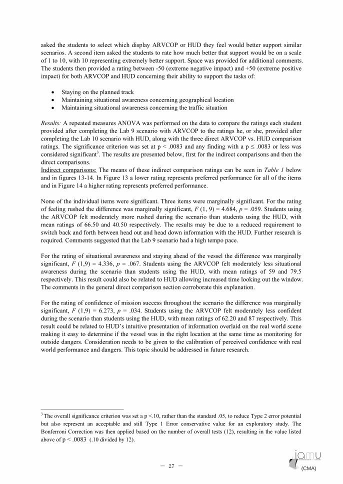
Indirect comparisons: The means of these indirect comparison ratings can be seen in Table 1 below
and in figures 13-14. In Figure 13 a lower rating represents preferred performance for all of the items
and in Figure 14 a higher rating represents preferred performance.
None of the individual items were significant. Three items were marginally significant. For the rating
of feeling rushed the difference was marginally significant, F (1, 9) = 4.684, p = .059. Students using
the ARVCOP felt moderately more rushed during the scenario than students using the HUD, with
mean ratings of 66.50 and 40.50 respectively. The results may be due to a reduced requirement to
switch back and forth between head out and head down information with the HUD. Further research is
required. Comments suggested that the Lab 9 scenario had a high tempo pace.
For the rating of situational awareness and staying ahead of the vessel the difference was marginally
significant, F (1,9) = 4.336, p = .067. Students using the ARVCOP felt moderately less situational
awareness during the scenario than students using the HUD, with mean ratings of 59 and 79.5
respectively. This result could also be related to HUD allowing increased time looking out the window.
The comments in the general direct comparison section corroborate this explanation.
For the rating of confidence of mission success throughout the scenario the difference was marginally
significant, F (1,9) = 6.273, p = .034. Students using the ARVCOP felt moderately less confident
during the scenario than students using the HUD, with mean ratings of 62.20 and 87 respectively. This
result could be related to HUD’s intuitive presentation of information overlaid on the real world scene
making it easy to determine if the vessel was in the right location at the same time as monitoring for
outside dangers. Consideration needs to be given to the calibration of perceived confidence with real
world performance and dangers. This topic should be addressed in future research.
3
The overall significance criterion was set a p <.10, rather than the standard .05, to reduce Type 2 error potential
but also represent an acceptable and still Type 1 Error conservative value for an exploratory study. The
Bonferroni Correction was then applied based on the number of overall tests (12), resulting in the value listed
above of p < .0083 (.10 divided by 12).
(CMA) (CMA)- 27 -
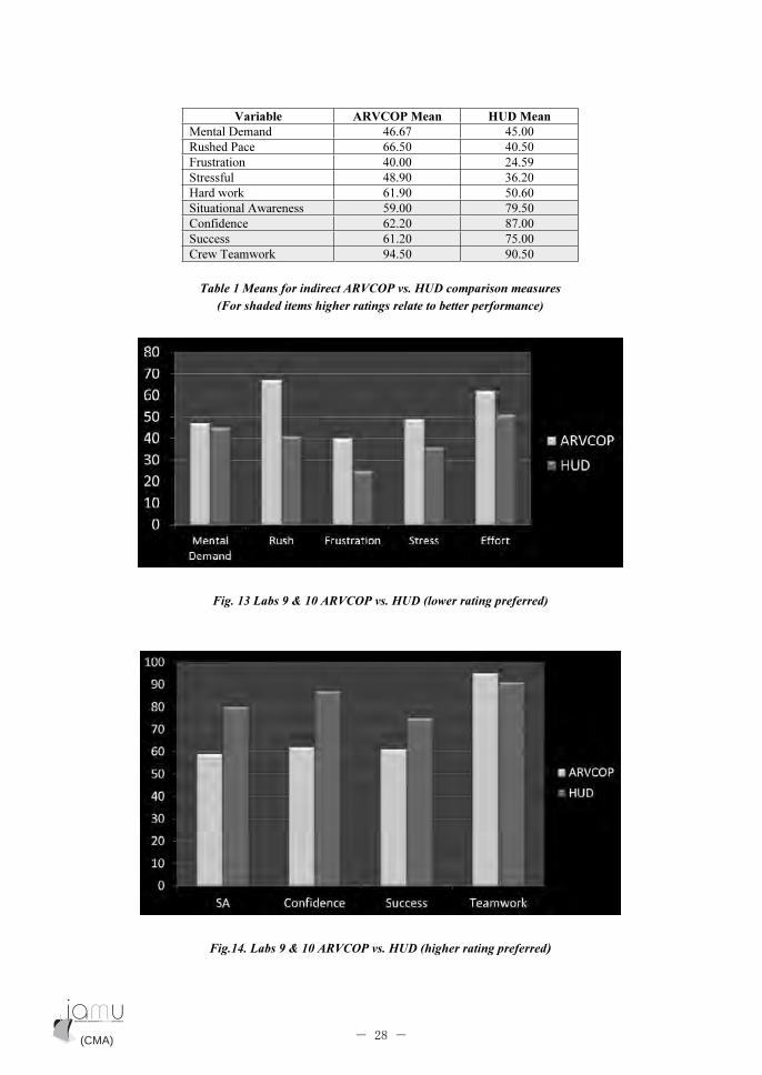
Variable ARVCOP Mean HUD Mean
Mental Demand 46.67 45.00
Rushed Pace 66.50 40.50
Frustration 40.00 24.59
Stressful 48.90 36.20
Hard work 61.90 50.60
Situational Awareness 59.00 79.50
Confidence 62.20 87.00
Success 61.20 75.00
Crew Teamwork 94.50 90.50
Table 1 Means for indirect ARVCOP vs. HUD comparison measures
(For shaded items higher ratings relate to better performance)
Fig. 13 Labs 9 & 10 ARVCOP vs. HUD (lower rating preferred)
Fig.14. Labs 9 & 10 ARVCOP vs. HUD (higher rating preferred)
(CMA) (CMA)- 28 -
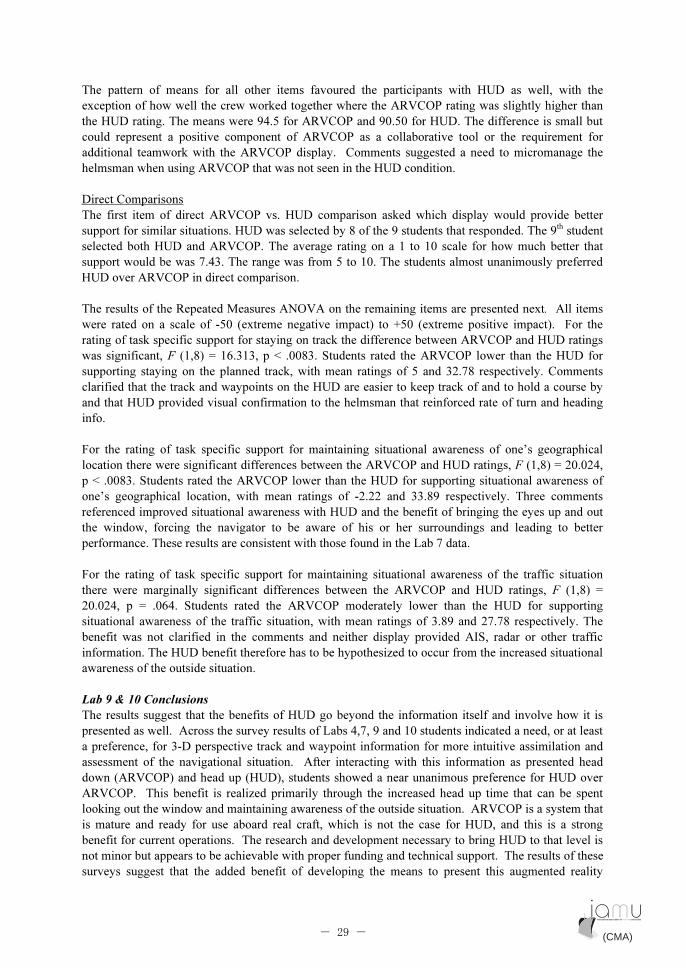
The pattern of means for all other items favoured the participants with HUD as well, with the
exception of how well the crew worked together where the ARVCOP rating was slightly higher than
the HUD rating. The means were 94.5 for ARVCOP and 90.50 for HUD. The difference is small but
could represent a positive component of ARVCOP as a collaborative tool or the requirement for
additional teamwork with the ARVCOP display. Comments suggested a need to micromanage the
helmsman when using ARVCOP that was not seen in the HUD condition.
Direct Comparisons
The first item of direct ARVCOP vs. HUD comparison asked which display would provide better
support for similar situations. HUD was selected by 8 of the 9 students that responded. The 9th
student
selected both HUD and ARVCOP. The average rating on a 1 to 10 scale for how much better that
support would be was 7.43. The range was from 5 to 10. The students almost unanimously preferred
HUD over ARVCOP in direct comparison.
The results of the Repeated Measures ANOVA on the remaining items are presented next. All items
were rated on a scale of -50 (extreme negative impact) to +50 (extreme positive impact). For the
rating of task specific support for staying on track the difference between ARVCOP and HUD ratings
was significant, F (1,8) = 16.313, p < .0083. Students rated the ARVCOP lower than the HUD for
supporting staying on the planned track, with mean ratings of 5 and 32.78 respectively. Comments
clarified that the track and waypoints on the HUD are easier to keep track of and to hold a course by
and that HUD provided visual confirmation to the helmsman that reinforced rate of turn and heading
info.
For the rating of task specific support for maintaining situational awareness of one’s geographical
location there were significant differences between the ARVCOP and HUD ratings, F (1,8) = 20.024,
p < .0083. Students rated the ARVCOP lower than the HUD for supporting situational awareness of
one’s geographical location, with mean ratings of -2.22 and 33.89 respectively. Three comments
referenced improved situational awareness with HUD and the benefit of bringing the eyes up and out
the window, forcing the navigator to be aware of his or her surroundings and leading to better
performance. These results are consistent with those found in the Lab 7 data.
For the rating of task specific support for maintaining situational awareness of the traffic situation
there were marginally significant differences between the ARVCOP and HUD ratings, F (1,8) =
20.024, p = .064. Students rated the ARVCOP moderately lower than the HUD for supporting
situational awareness of the traffic situation, with mean ratings of 3.89 and 27.78 respectively. The
benefit was not clarified in the comments and neither display provided AIS, radar or other traffic
information. The HUD benefit therefore has to be hypothesized to occur from the increased situational
awareness of the outside situation.
Lab 9 & 10 Conclusions
The results suggest that the benefits of HUD go beyond the information itself and involve how it is
presented as well. Across the survey results of Labs 4,7, 9 and 10 students indicated a need, or at least
a preference, for 3-D perspective track and waypoint information for more intuitive assimilation and
assessment of the navigational situation. After interacting with this information as presented head
down (ARVCOP) and head up (HUD), students showed a near unanimous preference for HUD over
ARVCOP. This benefit is realized primarily through the increased head up time that can be spent
looking out the window and maintaining awareness of the outside situation. ARVCOP is a system that
is mature and ready for use aboard real craft, which is not the case for HUD, and this is a strong
benefit for current operations. The research and development necessary to bring HUD to that level is
not minor but appears to be achievable with proper funding and technical support. The results of these
surveys suggest that the added benefit of developing the means to present this augmented reality
(CMA) (CMA)- 29 -

navigation information in a HUD would be worth the time and effort, as has been realized in other
domains such as aviation.
6. Presentation at 2011 e-Navigation Conference
In late October 2011, Captain Robert Moore, a well-respected expert in the field of maritime affairs
and co-chair of the annual e-Navigation Conference in Seattle, WA, wrote to the PI, Sam Pecota:
Dear Captain Pecota,
Two synergistic (I hope) things occurred today. First, I read through the paper
you and Eric Holder published in the October 2011 issue of the Journal of
Navigation, and then arrangements for one of the speakers lined up for
eNavigation 2011 fell through, leaving a slot open. I immediately thought that if
you were available and willing, a presentation based upon the paper would be an
admirable addition to the conference. I must apologize for the tardiness of this
request and frankly feel some embarrassment at not having considered you from
the beginning. Fred Pot and I are serving as conference co-chairs this year and
things have been organized somewhat differently than heretofore. Day 1 deals
largely with the evolution of e-Navigation and its impact upon particularly the
waterway management infrastructure. Day 2 focus is largely upon ECDIS, but
more the underlying complexity rather than mechanics of the display.
I expect John Eric Hagen, of the IMO e-Navigation Correspondence Group will,
in his presentation on Day 1, describe the revised conceptual architecture reported
by the group to NAV 57 during early summer. My thought would be to build on
the statement implicit in that architecture that while mariners now deal with AIS,
radar and ECDIS the technical tools providing e-Navigation information to the
mariner will change with experience and technological developments. One
potential route of the several now foreseen may well be HUD, either by itself or in
combination with other things. The presentation could also be used to reinforce
awareness of e-Navigation as a general maritime information environment
wherein technical devices move data and translate it into information immediately
useful for decision-making for all of the maritime community, not just positioning
and collision avoidance.
The PI could not refuse such a gracious invitation to speak at this prestigious conference and so
accepted. The title selected for the presentation (as suggested by Captain Moore) was simply
“Alternative Displays.”
The presentation was made on 30 November 2011 and was received quite enthusiastically by many
(not all!) conference attendees. This was especially gratifying since “Alternative Displays” was the
very last presentation to be delivered of some twenty plus over a two-day period. (The PowerPoint
slides used for the presentation are included in the documents accompanying this final report.) The
HUD demo video produced last year and included as part of the deliverables in Phase I as well as
video of the e-Navigation students steering the crewboat using ARVCOP were shown to a very
attentive and appreciative audience that was by that stage of the conference fairly well satiated with
PowerPoint presentations. Afterward, one of several professional mariner educators from the STAR
Center and Pacific Maritime Institute stated, “I wondered when someone was finally going to make
one of those things.” Somewhat surprisingly, three experienced ship pilots expressed great interest in
(CMA) (CMA)- 30 -

the HUD as well, particularly as an aid to docking vessels, something that was not even considered by
the researchers as a potential benefit of HUD. Clearly, we have not yet exhausted all research
possibilities for this device.
7. Conclusion and Notes on Further Research after Phase II
7.1 Final assessment of the Fall 2011 e-Navigation course
In general, the students who participated in the e-Navigation course were very positive about the
experience. Many asked if the course was going to be offered again, and if so, expressed an interest in
retaking it. At the last session, an exit survey was administered that asked student opinions about the
course overall. Below are the responses, as measured in Likert format, i.e., 1=strongly disagree,
5=strongly agree.
1. This course increased my watchstanding confidence. 4.25
2. This course improved my general watchstanding skills. 4.75
3. This course improved my radar skills. 4.75
4. This course improved my ECDIS skills. 4.75
5. This course improved my Bridge Team Management skills. 4.50
6. The pre-brief helped me perform better during exercises. 4.75
7. The de-briefs were a helpful learning opportunity. 4.75
8. This course is a valuable course in my curriculum. 4.50
9. The course appears to have been carefully planned. 4.82
10. The class followed the syllabus. 4.18
11. I felt that the lab sections reinforced the topic discussed. 5.00
12. I felt that the simulation exercises were realistic. 4.82
13. This course is practical and useful to those students for whom it was specifically planned. 4.91
14. I feel the opportunities to be involved in maritime research were valuable. 4.82
7.2 Future e-Navigation courses
With the completion of the Fall 2011 e-Navigation course on 14 December, research and development
to produce a college-level course in e-Navigation for the world’s maritime universities drew to a close.
The Model Course produced during Phase I of this research project coupled with the actual course
syllabus, lecture PowerPoints and Lab instructions produced by Cal Maritime Assistant Professor
Scott Powell using that Model Course, should provide any maritime instructor with the necessary tools
to create his or her own course in e-Navigation.
As for Cal Maritime, the decision whether to offer e-Navigation instruction to Marine Transportation
students as a stand alone course based on the IAMU Model Course or to incorporate components of e-
Navigation topics within already existing navigation courses has yet to be determined. What is not in
question however, is the need to introduce all future deck students to e-Navigation concepts and
systems, even as they are still being developed. Maritime universities can no longer afford to ignore
the inexorable movement toward the full implementation of e-Navigation by the world’s maritime
community. Our students must be prepared to enter into marine navigation environments unlike any
that have gone before.
(CMA) (CMA)- 31 -

7.3 HUD Research Planned for 2012
The search for a commercial marine navigation equipment manufacturer partner to help produce a
working, seagoing marine HUD prototype has still proven unsuccessful. Of the major equipment
manufacturers such as Jeppesen, Kelvin Hughes, Transas, Northrop Grumman, and Rockwell Collins,
none have shown a real interest in the project. A representative from Jeppesen was present at the 2011
e-Navigation conference in Seattle and observed the presentation “Alternative Displays.” While
expressing interest in the concept, he was in no way encouraging as to the possibility of us obtaining
funding for further research from his company. Although this is disappointing, it is not unexpected
given the state of the world’s economy, which continues to suffer major challenges. We continue to
believe that we are the only group actively engaged in the attempt to develop an augmented reality
maritime head-up display and that the whole concept continues to seem too futuristic to most.
Nevertheless, as our research to date has shown, HUD shows great promise as an effective way to
display crucial, timely navigational information to the mariner in a variety of situations and on a
variety of vessel types. For this reason alone, the researchers will continue to develop the HUD at
whatever pace the amount of future funding will allow.
As related in Section 3.2 above, the first hurdle in further HUD development to be overcome is the
conversion of the program from Adobe Air to the more robust and flexible C# language. It is hoped
that this will be accomplished early in 2012. Once the program has been rewritten in C#, extensive
testing in the simulator will have to be conducted to assess its operational and display qualities and
prove its reliability. After it is determined that the new C# program meets the required standards in a
simulated environment, the next challenge will be to procure the necessary hardware to bring the
device out into a real operating environment, i.e., on board one of the Cal Maritime small craft. To
accomplish that, the first step will be to identify a suitable type of display.
There are several possible existing display methods such as window projection similar to that used in
automobile HUDs and flip down combiners as used in aviation HUDs. These types of displays are
generally quite small and therefore probably inadequate for a maritime HUD application. In lieu of a
larger bridge window application, a more promising display type could be something similar to the
Samsung AMOLED display as seen in Fig. 15 below. While presently quite expensive, the price
should come down to a reasonable level once an adequate number of applications are identified and
production increases. If our HUD could be successfully coupled to such a display, we would be at
about the same level of development as ARVCOP is presently.
Fig. 15 Samsung 19” Transparent AMOLED Display
(CMA) (CMA)- 32 -
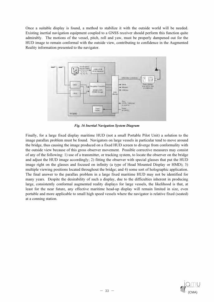
Once a suitable display is found, a method to stabilize it with the outside world will be needed.
Existing inertial navigation equipment coupled to a GNSS receiver should perform this function quite
admirably. The motions of the vessel, pitch, roll and yaw, must be properly dampened out for the
HUD image to remain conformal with the outside view, contributing to confidence in the Augmented
Reality information presented to the navigator.
Fig. 16 Inertial Navigation System Diagram
Finally, for a large fixed display maritime HUD (not a small Portable Pilot Unit) a solution to the
image parallax problem must be found. Navigators on large vessels in particular tend to move around
the bridge, thus causing the image produced on a fixed HUD screen to diverge from conformality with
the outside view because of this gross observer movement. Possible corrective measures may consist
of any of the following: 1) use of a transmitter, or tracking system, to locate the observer on the bridge
and adjust the HUD image accordingly; 2) fitting the observer with special glasses that put the HUD
image right on the glasses and focused on infinity (a type of Head Mounted Display or HMD); 3)
multiple viewing positions located throughout the bridge; and 4) some sort of holographic application.
The final answer to the parallax problem in a large fixed maritime HUD may not be identified for
many years. Despite the desirability of such a display, due to the difficulties inherent in producing
large, consistently conformal augmented reality displays for large vessels, the likelihood is that, at
least for the near future, any effective maritime head-up display will remain limited in size, even
portable and more applicable to small high speed vessels where the navigator is relative fixed (seated)
at a conning station.
(CMA) (CMA)- 33 -
8. Appendix
8.1 e-Navigation course lecture presentations
�
(CMA) (CMA)- 34 -
Appendix Appendix

(CMA) (CMA)- 35 -
Appendix Appendix

�
�
��
�
(CMA) (CMA)- 36 -
Appendix Appendix
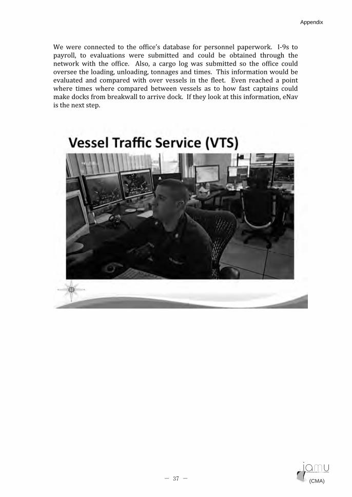
�������� ������� �� ��� � ������ �������� ��� �������� ����������� � ����� ��
��������� �� ���������� ����� �������� ��� ������ ��� ������� ������� ���
������ ���� ��� � ����� � ����� �� ������ ���� ���� �������� ��� ��� � ���� ������
��������������������������������������������!����� ����������������
��������� ��� ������������� ����� �������� �� ��� ����� � "��� �������� �� ����
������ ����� ������ ��������� ������ �������� ��� �� ���� ��� ������� ������
����������� ������������������������������� ����������������� ���������#���
�������$������
�
(CMA) (CMA)- 37 -
Appendix Appendix
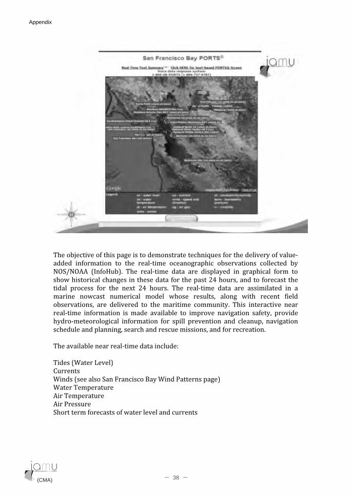
��
�
!�����%������� ����������������������������&���� ���������������� �������
������ � ������� �� ��� ��������� ������������� ����������� ��������� ���
#'()#' � *� �+��,�� !��� ��������� ���� ���� ���������� �� ���������� ���� ��
��������������������������������� ����������-.������������� ����������
����� �������� ��� ��� �$� -.� ������� !��� ��������� ���� ���� ����������� �� ��
������ ������ ��������� ������ ������ �������� ����� ���� ����� �����
������������ ���� ���������� �� ��� �������� ��������� !���� ��������� ����
��������� � ������� ��� ����� ���������� �� �������� �������� �� ���� ��������
�������������������� � ������� ��� ������ �������� ��� �������� ��������
������������������������������������������������ ��������������
�
!������������������������������������/��
�
!�����*�����0����,��
1�������
�����*���������(��2��������3�������4���������,��
�����!�����������
���!�����������
���4���������
(�������� ��������� �����������������������
�
(CMA) (CMA)- 38 -
Appendix Appendix
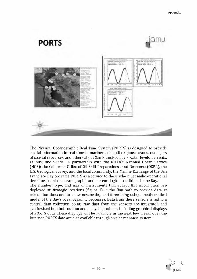
�
��
�
!���4��������'������������5����!����(����� *4'5!(,� ����������� ����������
�������� � �������������������������������������������������������������
� ���������������������������������(��2��������3��������������������������
�������� ��� ������ �� ���������� ���� ��� #' ��� #������ '���� (�������
*#'(,6� ���1��� �����' ����� �'���(�����4��������������5�������*'(45,�� ���
7�(��8����������(�������������������������������9�����"$������� ����(��
2��������3�����������4'5!(��������������������������������������������
������������������������������������������������������������3����
!��� ������� ����� ��� ��$� � � �������� ��� ������� ���� � ������� ����
��������� �� �������� �������� * ������ :,� �� ��� 3��� ���� �� �������� ���� ��
�������� ������������������������������ ���������������������������
������� ����3�����������������������������;��� ������������������� �������
������ ���� ��������� ���6� ���� ���� ���� ��� ������� ���� �������� ���
������<������� ������������������������������������������������������
� �4'5!(������!�������������������������������� �� ����$� �����������������
������4'5!(������������������������������������������������������ �
�
(CMA) (CMA)- 39 -
Appendix Appendix

�
(CMA) (CMA)- 40 -
Appendix Appendix

(CMA) (CMA)- 41 -
Appendix Appendix

�
�
(CMA) (CMA)- 42 -
Appendix Appendix

5������2�������
1� �����/�4������������� �������������������������������������������
������������* �������5�����,�
#��1� �����/�(����������������� ����������������������
4������ �������/� �
0������������������ �������
0������������������������������������
�
(CMA) (CMA)- 43 -
Appendix Appendix

�
��
�
5=1'4� ����<��� �������� ������� �� �������� ��������� ��������� �� ����
������������������������������� � � �������������������� ����������
������ ������ �� >;� ��� �� ����� ����� �� � ���� �������� ������� � ��������
������� ����� ����� ������� ��$���<��� ����� ��������� ��� �������
������������������������������
�� 5=1'4���������������������������������������� ����������������������
�����������%�������������������������������������������������������������
��%������������������ 5=1'4����������������9������(�������������������
������������������������������ ��������������������� ����������� ��������
�������������������������
(CMA) (CMA)- 44 -
Appendix Appendix
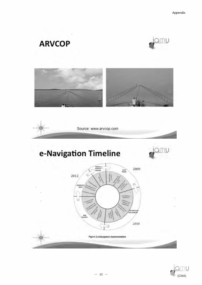
�
(CMA) (CMA)- 45 -
Appendix Appendix
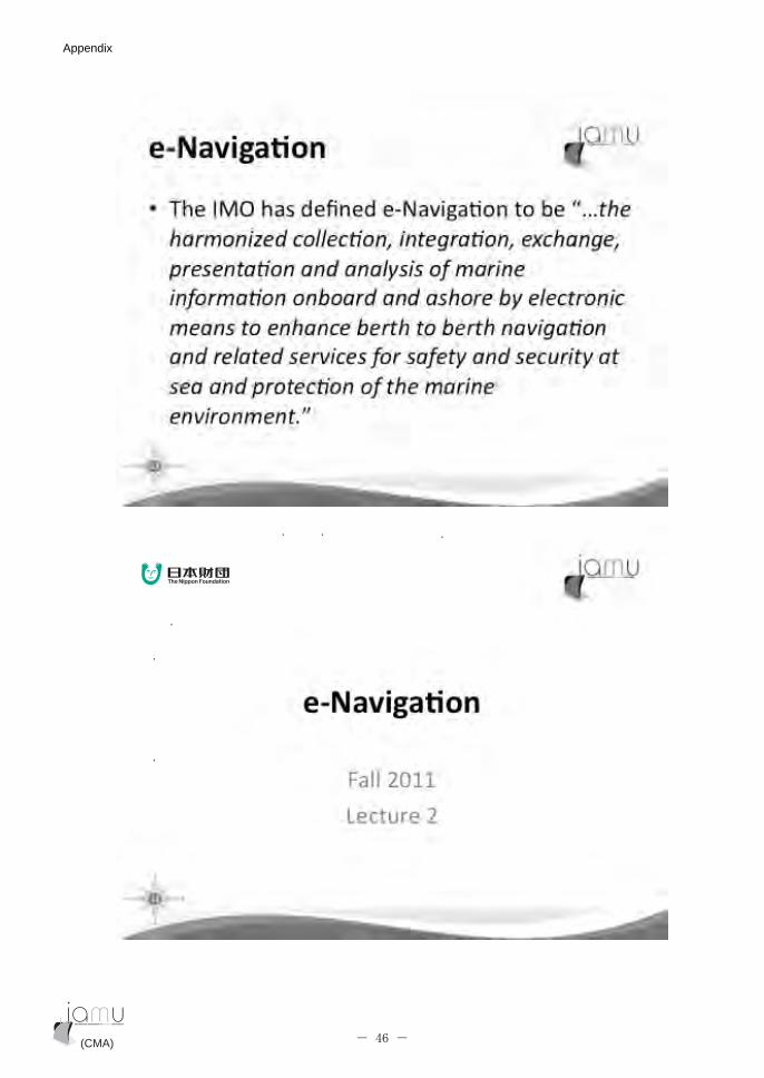
�
�
(CMA) (CMA)- 46 -
Appendix Appendix

�
�
(CMA) (CMA)- 47 -
Appendix Appendix
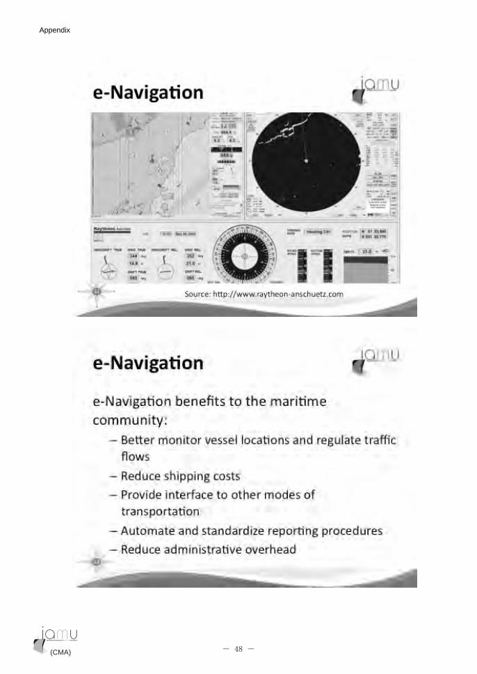
�
�
(CMA) (CMA)- 48 -
Appendix Appendix
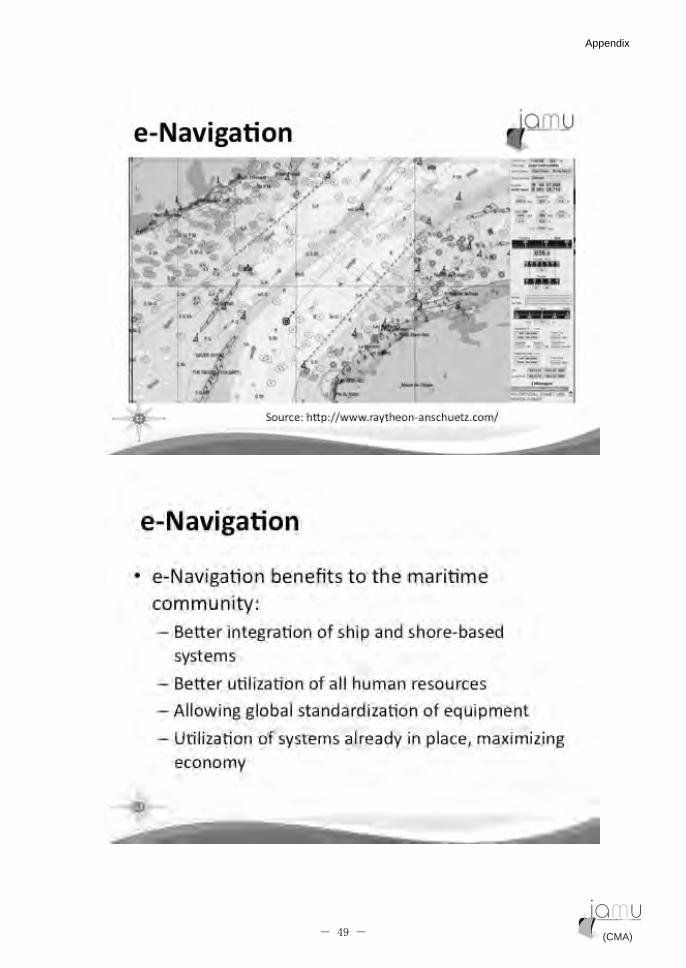
�
�
(CMA) (CMA)- 49 -
Appendix Appendix
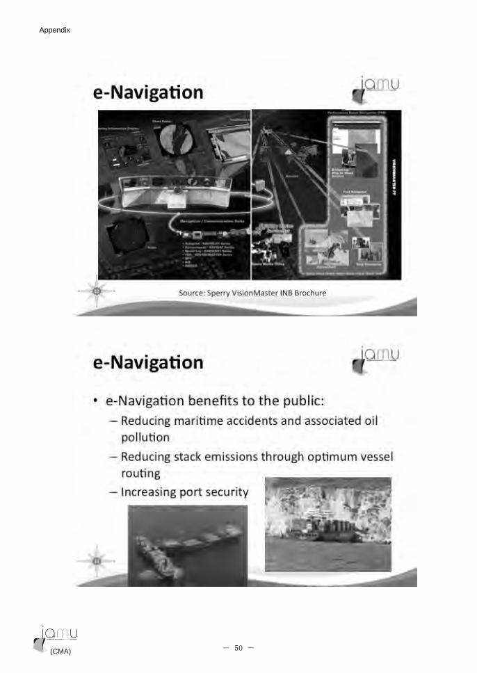
�
�
(CMA) (CMA)- 50 -
Appendix Appendix

�
�
(CMA) (CMA)- 51 -
Appendix Appendix

�
�
(CMA) (CMA)- 52 -
Appendix Appendix
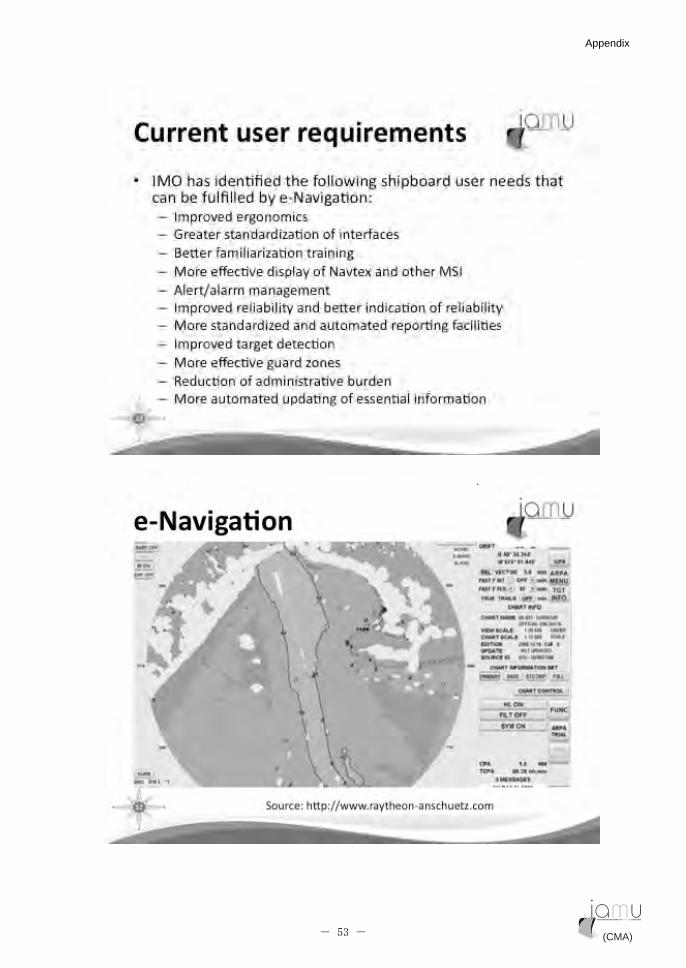
�
�
(CMA) (CMA)- 53 -
Appendix Appendix

�
��
�
(CMA) (CMA)- 54 -
Appendix Appendix

8�������� ������������*:�?�,�
�
�
(CMA) (CMA)- 55 -
Appendix Appendix
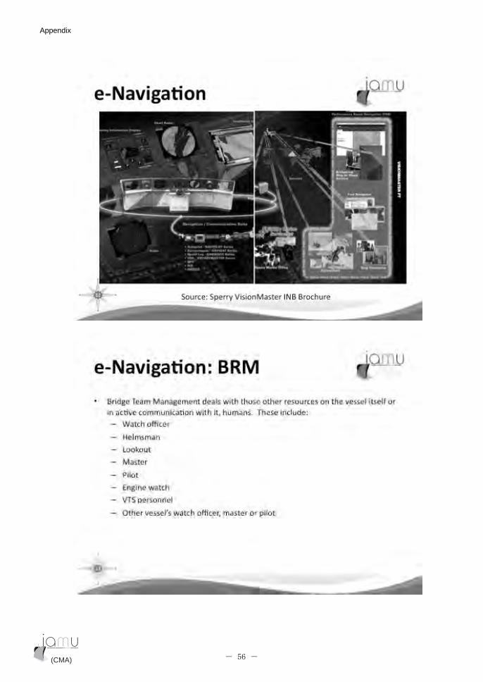
�
�
(CMA) (CMA)- 56 -
Appendix Appendix

�
�
(CMA) (CMA)- 57 -
Appendix Appendix

�
�
(CMA) (CMA)- 58 -
Appendix Appendix

�
�
(CMA) (CMA)- 59 -
Appendix Appendix
�
�
(CMA) (CMA)- 60 -
Appendix Appendix
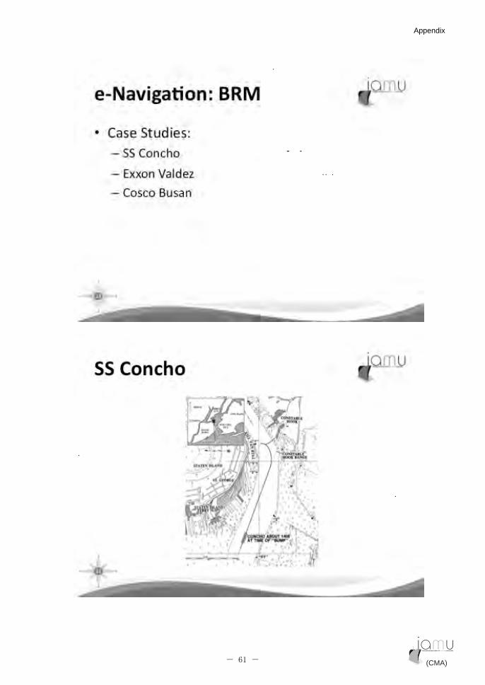
�
�
(CMA) (CMA)- 61 -
Appendix Appendix
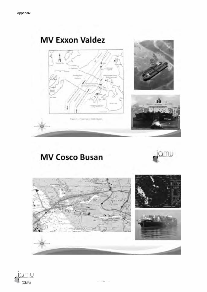
�
�
(CMA) (CMA)- 62 -
Appendix Appendix
��
�
(CMA) (CMA)- 63 -
Appendix Appendix
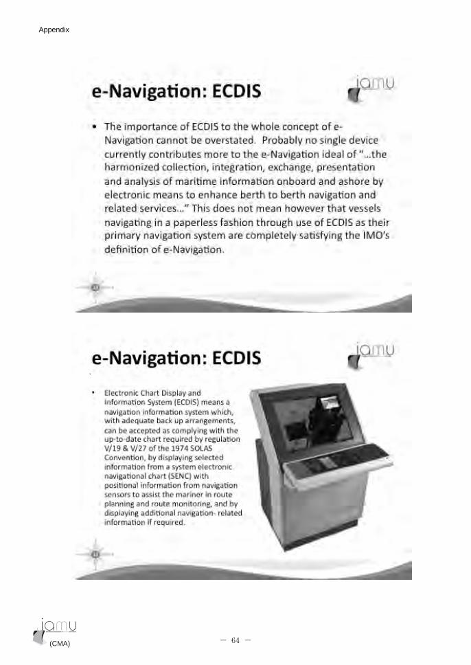
�
�
(CMA) (CMA)- 64 -
Appendix Appendix

�
�
(CMA) (CMA)- 65 -
Appendix Appendix
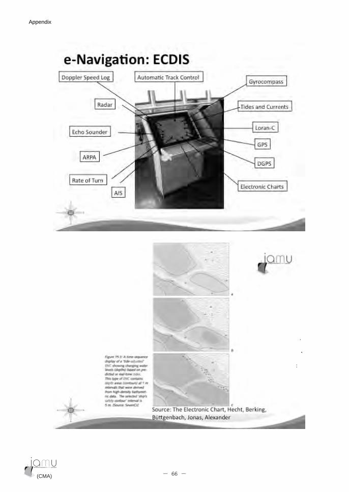
�
�
(CMA) (CMA)- 66 -
Appendix Appendix
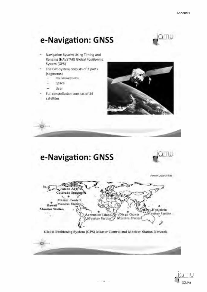
�
�
(CMA) (CMA)- 67 -
Appendix Appendix
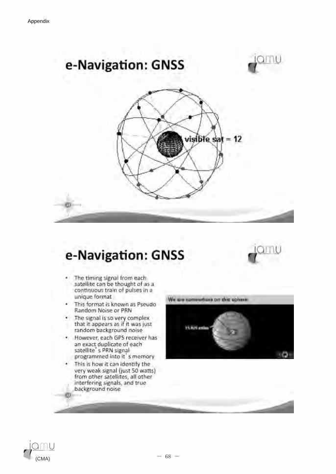
�
�
(CMA) (CMA)- 68 -
Appendix Appendix

�
�
(CMA) (CMA)- 69 -
Appendix Appendix
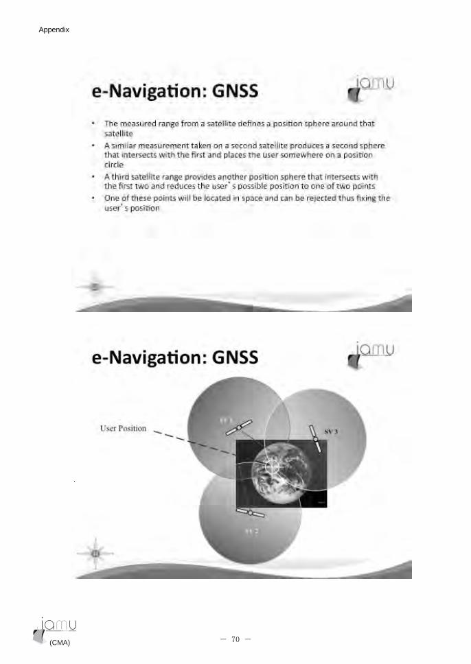
�
�
(CMA) (CMA)- 70 -
Appendix Appendix

�
�
(CMA) (CMA)- 71 -
Appendix Appendix

�
��
�
(CMA) (CMA)- 72 -
Appendix Appendix
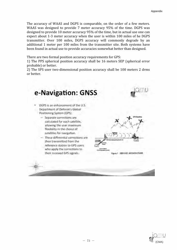
!������������� �� (����;84(� ��� ������������ �� ���������� � �� ����������
� (����� �������� �� �������� @������ ��������� �AB� � � ��� ����� ;84(�����
������������������:C����������������AB�� ������������������������������
�$���������:�>�����������������������������������:CC�������� ����;84(�
��������� '���� :CC� ������� ;84(� ��������� ����� �������� �������� ��� ��
���������:����������:CC������� ���� ��� �������� �����3��� ������������
���� ���������������������������������������������������������������
�
!������������ ������������������������&�������� ���84(/��
:,�!���44(������������������������������������:D�������("4�*����������������
��������,�����������
-,�!���(4(��������������������������������������������:CC�������-������
����������
�
�
(CMA) (CMA)- 73 -
Appendix Appendix

�
�
(CMA) (CMA)- 74 -
Appendix Appendix

��
�
��
(CMA) (CMA)- 75 -
Appendix Appendix

�
4������������������������������������������������������ �����������������
��� ������ ���� ���� ����� ����� ������ ������ ����� ��� �������� ���� �� ��������
������*�����������������������,���"���������E������E������ �������������
��<��� �����������������������84(������ �������84(������������3��E�������E�
����������������������������������������������������������������� �������
����� ����� ���������� ������� 99(��� ��� ����� � ��������� 9���������
� �������� ������������ ����������*14 ,�� ���� �������������� ����������
*!14 ,����������������� � ����������������������������� ������ ���
� ������� ���������� ���� �� �������� ������ ������ ����� ��� ����� ���
������������;�������� ����������������������������������������=������!�� ���
(������� ��������� ������ ��� ��� ��� ���������� �� ������ �(� ����� ��� ����
���������
�
�
(CMA) (CMA)- 76 -
Appendix Appendix
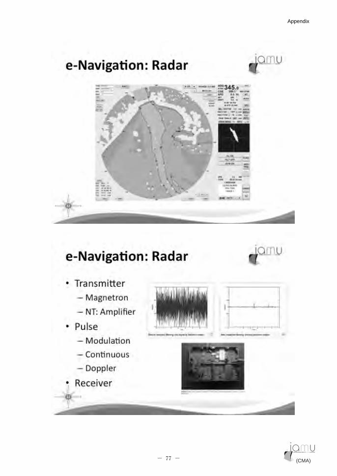
�
�
(CMA) (CMA)- 77 -
Appendix Appendix

�
�
(CMA) (CMA)- 78 -
Appendix Appendix

�
�
(CMA) (CMA)- 79 -
Appendix Appendix

��
�
�������� � ���������������������������������=+2����������������������
������������E������ �����������E������������������������������ ��'������
�������� ������������������89;((��&������� �'���������������������������
�������� �������������� ��������������������������
!��� �(���������������������������������������������������������������
�����=+2����������������������������� ������������������.�ACC������������
������������������� ������������������������������(�� �'����<���!����
;�������9������� ������*('!;9 ,��������������������������������������
��������������������������������������� �
(CMA) (CMA)- 80 -
Appendix Appendix

�
��
�
"���� �(��������������� ����=+2�������������=+2�!;9 ���������������
=+2� ;(1� ���������� ��� ������� ������ ��������� ������������ ����� *�"1�
D::D-)#9" �C:?>,� �� ��������������������������� ������� * �(�(�������,��
4��������������� �������������������������� �����������������$�����
������� �������� �������� ������ *����� 84(,� ���������� �������� �� �������
��&����� �� ������� 8#((� ��������� ��� �������� ������� �� ������� ��� �����
�������� '���� � ������� ��������� ��� ��� �(�� � � ����������� ��� �������������
������� ���� ���������� �&������ ������� ������� ������ ����
���������� ��� �(��&������� ������ ������ �������� �������� �������
� ���������������������������������������'����� ��������������������
� � ���� ����� � � ������ ����� ��� ������ ��� �������� ��� "! � ������ ����� ���
����������
!��� �(� ����������������������� ������������������������������
����������� � � ������� �� ��� �������� �� ��� ���� ����� ��� ������� ��� �����
�������� !����������� ���� ��D� ��� 89(F� 29� ��������� ����� -A� ��� :-�A� �+<�
������� ����� +;01� ������ ���������� ������� ���� ��� ������ ������ ���
��������������������������������������������������������������������
��� ������ ���������� ��� �� ������ ������� �� ��� ��� ��� ������
������������ ����� ���� ����� ������� !��� ������ ��������� ��� ��������
������ ��������� ������ ���� � ��� ����� ������� ��� ������������
������������������������������������������
"������������������ ������������������������� *���,����������������
������ ����������������������� � ���������������������������� ��������
(CMA) (CMA)- 81 -
Appendix Appendix
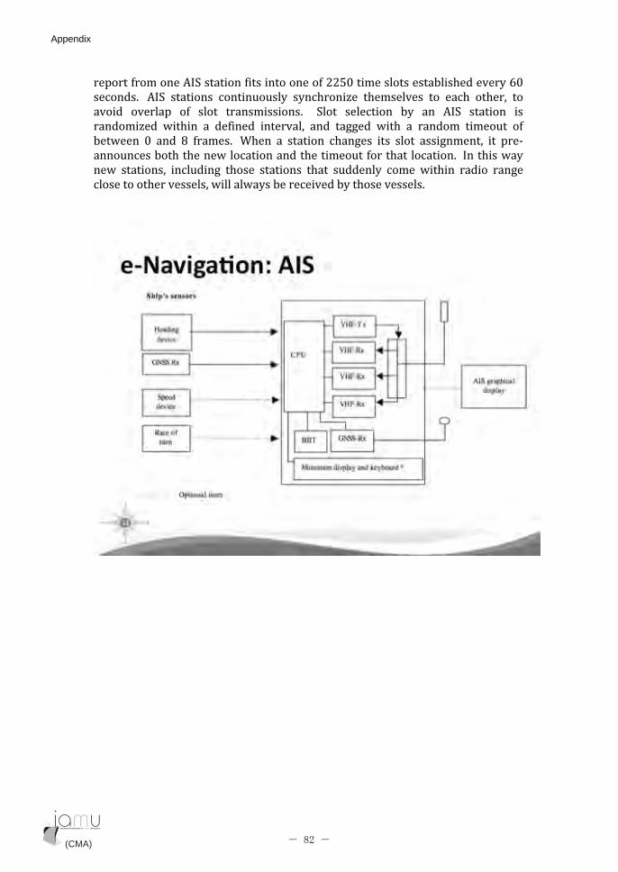
������ ������� �(������ ���������� �--AC���������������������������DC�
��������� �(� ������ ���������� �������<�� ���������� �� ����� ������ ��
������ �������� � � ���� �������������� (��� �������� ��� �� �(� ����� ���
������<��� ����� �� �� ���� �������� ��� ������ ���� �� ������ ������ � �
������ C� ��� ?� �������� ���� �� ����� ������� ��� ���� ��������� �� ����
������������������������������������ �������������������������
��� ������� �������� ����� ������ ��� �������� ����� ����� ������ �����
�����������������������������������������������������������������
�
�
�
(CMA) (CMA)- 82 -
Appendix Appendix
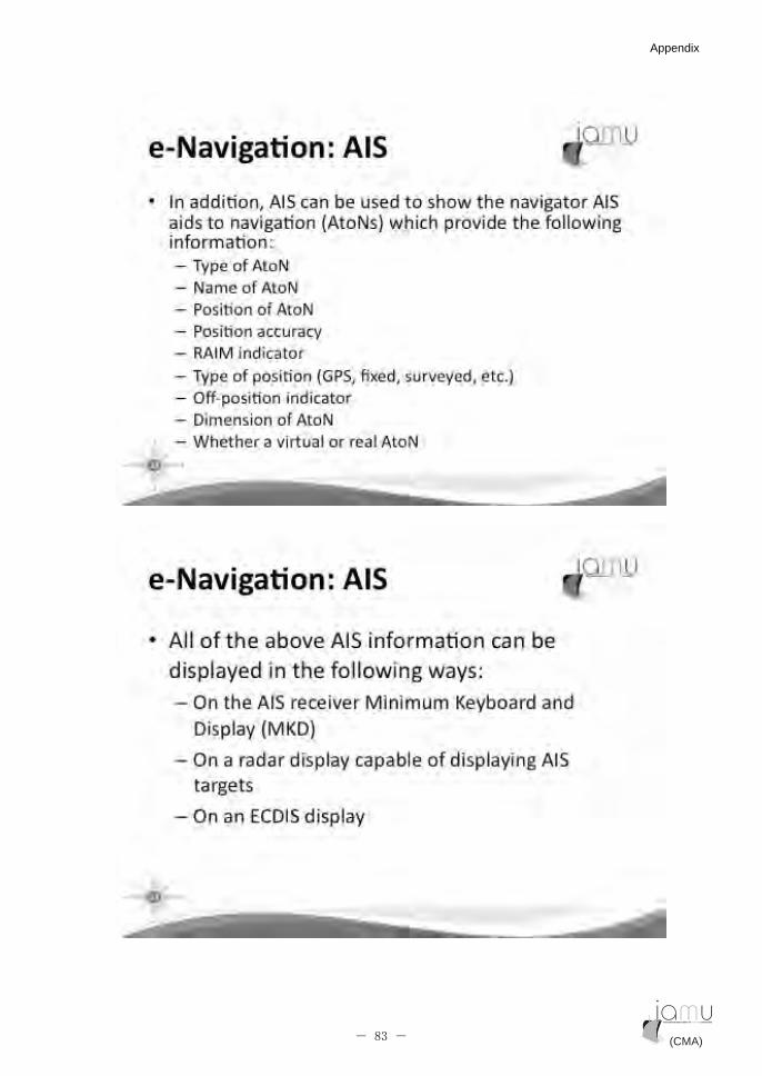
�
�
(CMA) (CMA)- 83 -
Appendix Appendix
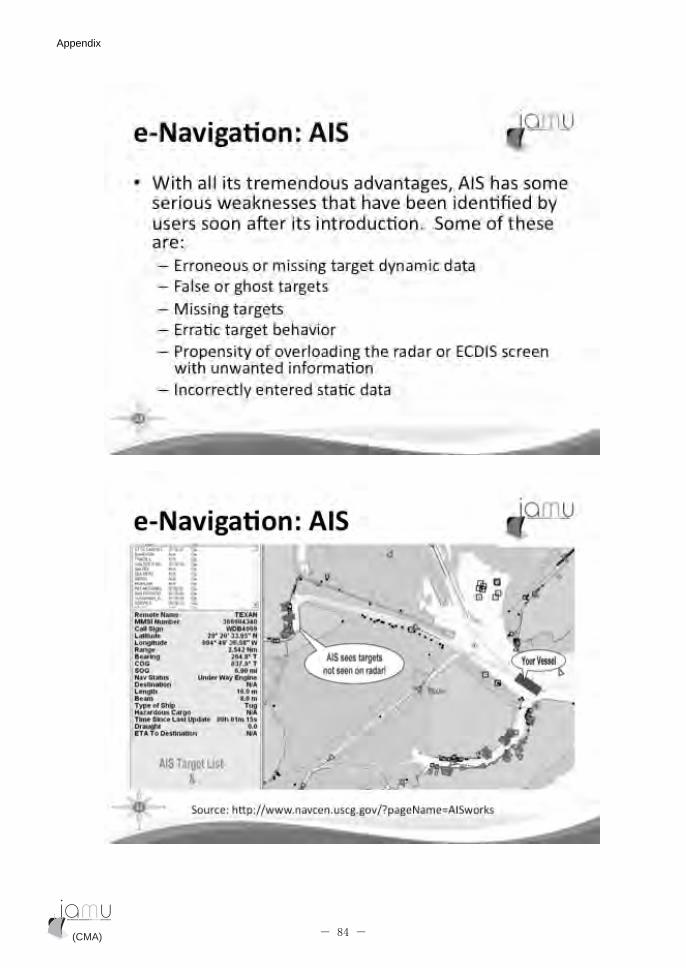
�
�
(CMA) (CMA)- 84 -
Appendix Appendix

�
�
(CMA) (CMA)- 85 -
Appendix Appendix
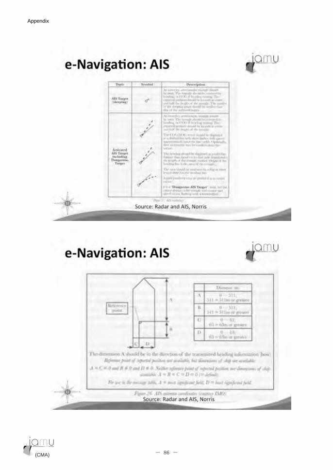
�
�
(CMA) (CMA)- 86 -
Appendix Appendix

��
�
(CMA) (CMA)- 87 -
Appendix Appendix
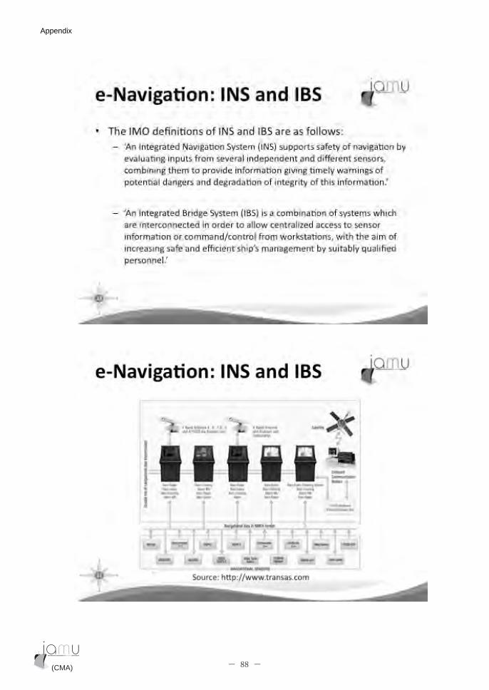
�
�
(CMA) (CMA)- 88 -
Appendix Appendix
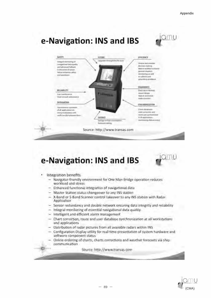
�
�
(CMA) (CMA)- 89 -
Appendix Appendix

�
�
(CMA) (CMA)- 90 -
Appendix Appendix
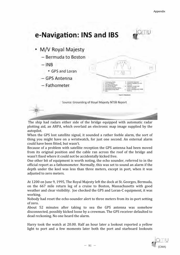
�!��� ����� ���� ������� ������ ����� � � ��� ������� �&����������� �������� ������
����������� �� 54 �������������������������������� ������������������ ���
���������
���� ���84(� ���� ��������������� �� ��������������� ������������� �������� �
���� ��������� ����� �� ������������ ��� %��� ��� ������� � �$����� ������
��������������� ��������������
3�������� ����������������������������������84(�������������������
���� ��� �������� ������� ��� ��� ������ ��� ������� ��� ��� � � � ��� ������� ���
����� �$���������������������������������������� �����
'����������� ��&������������������������������������� �������������
� ����������������� �����������#������������������������������������ ����
����� ����� ��� ��������� ����� ��� ������������ �$���� �� ��������� �� ����
��%�������<�����������
�
�:-CC���G������:��A��!���5�����9�%������ �����������(��8��������3��������
�� ��� DD@� ����� ����� ���� � � �� ������� �� 3����� 9����������� ���� �����
����������������������������G��������������84(����0����1��&�������������
��������
#������������������������������������������������ ������������������
� �<�����
���� A-� ������ � ��� ����� �� ���� ��� 84(� ���� ���� ��������
����������������������������������������������!���84(������������ ��������
��������������#���������������������
�
+����� ���� �������� �� -C�CC��+�� � ������� ����� �� ������� �������� �� �������
����� �� ���� ��� �� ��� ������ ����� ���� ��� ���� ��� ��������� ��������
(CMA) (CMA)- 91 -
Appendix Appendix

������������������������+�����������������!�������������������������
����������������������������������� ������ �����������������������
!���5�����9�%�������������������������!��� ���������������4���������
�����������������������!����������������������"��������1�����:D�������
����������!���������������������������� ��������������������
!��� ���� �� ��� ������� ����� �� --CC�� +�� ����� ������ ��� ��������� �������
������������������ ����������������������������������������������������
� � ���3���� �� ��� ����� �����33�� �� ���� ��� ����� ���� ���33������� ������
�����������������������������������������������84(���������
!����������������������������������������������������������������������
������� ���� �������������������������������
�
�
�
�
(CMA) (CMA)- 92 -
Appendix Appendix
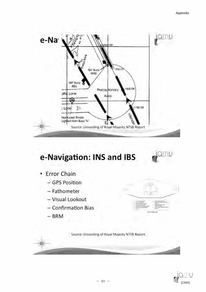
�
�
(CMA) (CMA)- 93 -
Appendix Appendix
��
�
(CMA) (CMA)- 94 -
Appendix Appendix

�
�
(CMA) (CMA)- 95 -
Appendix Appendix
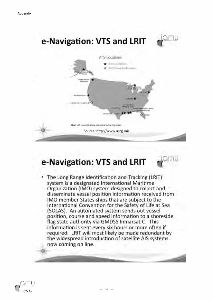
�
��
�
(CMA) (CMA)- 96 -
Appendix Appendix
��
��
�
(CMA) (CMA)- 97 -
Appendix Appendix
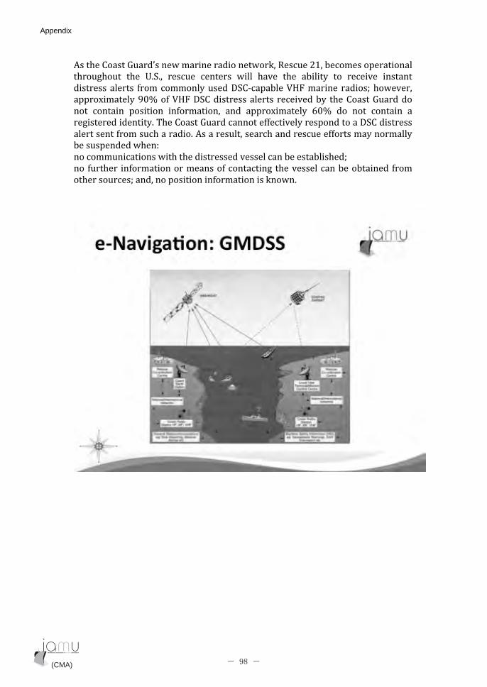
�����1����8�����������������������������5������-:��������������������
��������� ��� 7�(��� ������� ������ ����� ����� ��� ������� �� �������� ����
�������������� �����������������;(1���������=+2������� ������6����������
�����$��������CB�� �=+2�;(1��������������� ������������ ���1����8��������
�� ����� ������� � �������� ��� �����$������� DCB� ��� �� ����� ��
�����������������!���1����8���������� �������������������;(1���������
�������� ������������������ ����������������������������� ����������������
���������������/�
������������������������������������������������������6�
�� ������ � ���������������� �������� ����������������������� ����
������������6��������������� ��������������� �
�
�
�
(CMA) (CMA)- 98 -
Appendix Appendix

�
�
(CMA) (CMA)- 99 -
Appendix Appendix
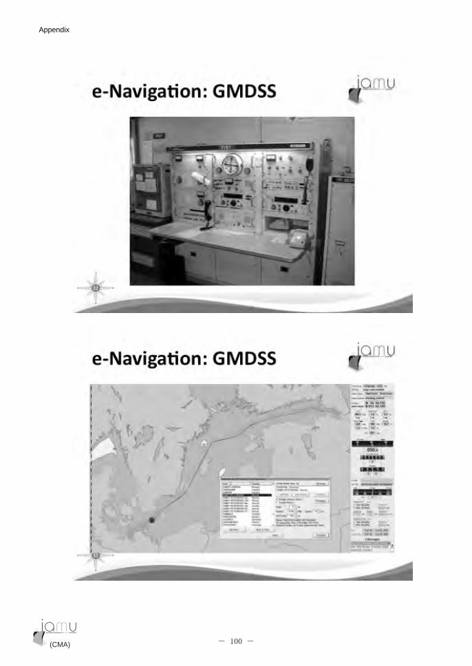
�
�
(CMA) (CMA)- 100 -
Appendix Appendix
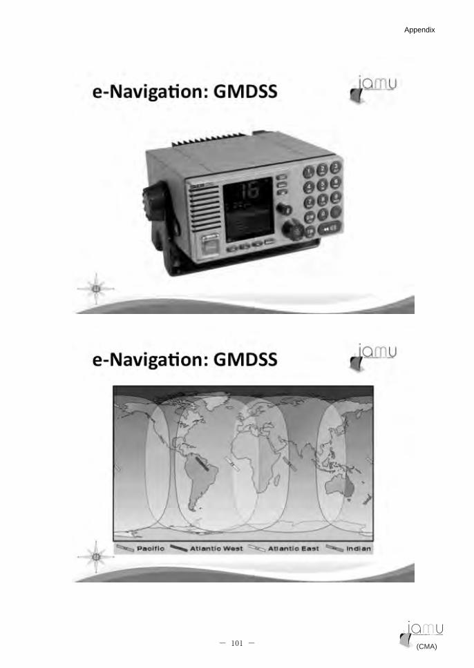
�
�
(CMA) (CMA)- 101 -
Appendix Appendix
�
�
(CMA) (CMA)- 102 -
Appendix Appendix

��
�
(CMA) (CMA)- 103 -
Appendix Appendix
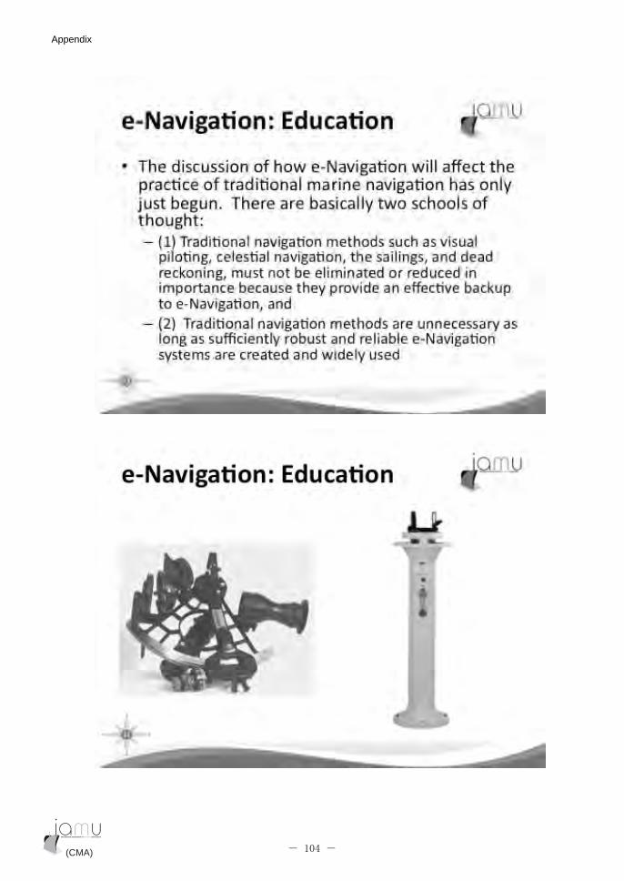
�
�
(CMA) (CMA)- 104 -
Appendix Appendix
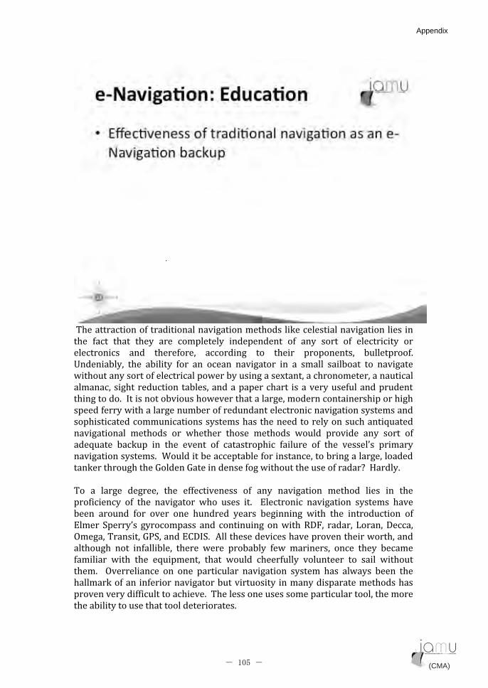
�!����������� ������������������������������������������������������
��� ��� ��� ���� ���� ���������� �������� � � ��� ���� � � ���������� ���
���������� ��� ���� ����� ��������� �� ����� ��������� ��������� ���
7��������� ��� ������� ��� �� ����� �������� �� �� ������ �������� �� �������
�������������� �����������������������������$�������������������������
�������������������������������������������� ������������� ������������
�����������������������������������������������������������������������
������ ������������������������ �����������������������������������
����������������������������������������������������������&�����
���������� ������� ��� ������� ����� ������� ������ �������� ��� ���� � �
���&���� ������� �� ��� ���� � � ����������� ������� � � ��� ��������� ��������
�������������������������������������� ���������������������������������
���������������8�����8���������� ����������������� ������H��+�������
��
!�� �� ������ �������� ��� � ��������� � � ��� �������� ������ ����� �� ���
��� ������� � � ��� �������� ���� ����� ��� � "�������� �������� ������� �����
���� ������ ��� ����� ��� ������� ������ ������� ���� ��� ��������� � �
"����� (�������� ������������ ��� ������� ������5;2�� ������� 0�����;������
'������!������84(�����"1;�(��� �����������������������������������������
�������� �� � ��������� ����� ����� ��������� ��� ��������� ���� ���� �������
�������� ���� ��� �&������� ��� ������ ����� ����� �������� �� ����� ������
����� � '����������� �� ��� ���������� �������� ������ ���� ������� ���� ���
���������� ���� �������������������������� ��������������������������
������������� �����������������!��������������������������������������������
�����������������������������������
��
(CMA) (CMA)- 105 -
Appendix Appendix
!��� &������ ������� ���� ����� ��� �������� � � ��������� ������ ��������
��������������������������� ���#�������H�
�
�
(CMA) (CMA)- 106 -
Appendix Appendix
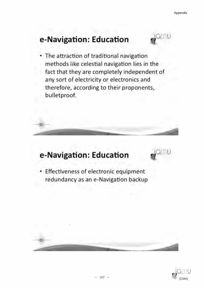
�
��
�
(CMA) (CMA)- 107 -
Appendix Appendix

!������ �� ������ ��� ��������� ��������� ������� �� ��� ������ ��#��������
�������������������������������������������� �������������������
����� �������� �� �� ���������� � ��� ����� �� ���������� ��������� ������
��������H� �!�������������������� �������� ����� ���������� �#���������������
����� ������� ���� ���������� ��� ��������� ������� �� ���������� ������
��� ����� ��������� ��� �������� �������� ��� ������ ������� ���� �����������
3��������� �����������������������������������������H��G������������
���������� ���������� � �������������� ������� ��� ����������� ������������
���������&������ ���������������������������
�
�
(CMA) (CMA)- 108 -
Appendix Appendix

�
�
(CMA) (CMA)- 109 -
Appendix Appendix
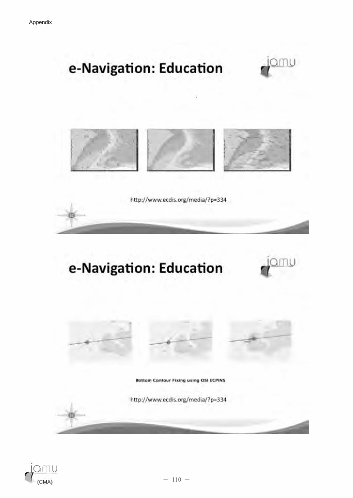
�
�
(CMA) (CMA)- 110 -
Appendix Appendix

������������������������������84(����5 ; 5����������� �$�� �������� �
"1;�(����������������������5 ; 5����������������� �������������������
� ����������������� �������������������������<����������������!����������
���%���� ����������������������������������� ������� ����������
��&�����������������������+�������� ���84(�����������������������������������
���������� �I� ����������84(����������������������� �I�������������84(���!���
��������������� ��������<�����"1;�(��������������#�� ������&���������
���������� ������������������&���������������� ��������!�����������
���������� ����J���������� �$���������������������������� ������84(����
��������� �84(������������������ �"1;�(�������� ����������������������
�$����������������������������������������84(�����������������������
���������������� �"1;�(� ��������4������� �$���"1;�(�*0����� �4�����,������
��&������������������ �������������������$���������� ��������
��������&������+���������������������������� ��������%���������������
������������������������������������������&��������������� �$�����"1;�(����
������������������������������������$����� ������������� ������K�
(CMA) (CMA)- 111 -
Appendix Appendix

��
�
!��� ��������� �� ����� ����� �� ��� ���� ���� ���� ��� ��� ��� ���� ����� ��6� ��
��������������� ������������������������������������������� ���������
���������������6�������������� �����������&������������������������������
��� ����6� ��������� ������� ��� ����� �� ��� ������� ������ ���� �������� � �
���������������� ���������� � ��������� ��� ��&����� �� ��� �������� � ������
�����
�� ���� � � 84(� �������� ��� �������� ��� ����<�� ��� ;5� ����� �� "1;�(� ���
������ �� ��������� �$��� ������� �� ������ �� �������� �������� ��������� �����
#��� ��� ����� � � 84(� ���� ����� ���� ����� � � ��������� � ������� �� �����
5 ; 5�� 2����������� ��� �������� ���� ��� ������� � �� ���� ��������� ���
������������ �$�������������$���������������������������������� ������
��������������� �$����������� ����������(����������������� �������������
���������� ��������������������������������������������������������
����������������������������������������&���������������� ���������������
&����� ��� ����� �� ����� ��� �������� ����� ��� ��� ���� �� ������ ���
������������ ���������� ;5� ��� "4� ������ ���� ���� ���� ������� ����� ��� ���
��� ��� �� 1'8� ��� ('8�� ���� �� I;5� ������� �� ��� ��� ���� ���� ���� ���
�������� ������ ��������� � ������� ��� ����� &������� ��������������� ����
������������������������������������������ ������������
(CMA) (CMA)- 112 -
Appendix Appendix

�
�
(CMA) (CMA)- 113 -
Appendix Appendix

8.2 e-Navigation course lab instructions
NAU 395 e-Navigation
Fall 2011
Lab 2 Instructions
Name: ____________________ Name: ____________________
Prince William Sound
Purpose of lab:
1) Understand the benefits of e-Navigation to mariners, the maritime community, and the
public through an analysis of the grounding incident of the Exxon Valdez.
2) Practice using e-Navigation concepts to conduct an outbound trip through the Valdez Arm.
Specific objective:
Navigate your vessel safely using Visual Watchstanding, Radar/ARPA, ECDIS, VHF and AIS.
(CMA) (CMA)- 114 -
Appendix Appendix

Scenario:
Your vessel is departing the Alyeska Marine Terminal, Valdez, Alaska and will proceed
through Valdez Narrows to the outbound lane of the Traffic Separation Scheme. Chart 16708 may be
used as a reference:
Task 1: Outbound trip of Exxon Valdez recreated using simulation.
Task 2: Create an outbound route via the Traffic Separation Scheme using ECDIS.
Scenario Parameters:
The following instructions and restrictions apply to this scenario:
(1) Monitoring your route: create a route with ECDIS. Pay particular attention to hazards
along the route. Deviation from the route may be necessary given the ice conditions in the
Valdez Arm
(2) Monitoring your route: Maneuver your vessel based on information provided to you from
the VTS
(CMA) (CMA)- 115 -
Appendix Appendix
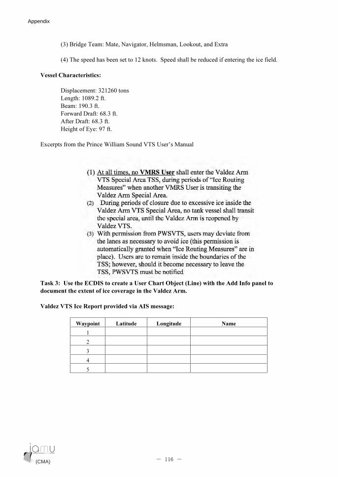
(3) Bridge Team: Mate, Navigator, Helmsman, Lookout, and Extra
(4) The speed has been set to 12 knots. Speed shall be reduced if entering the ice field.
Vessel Characteristics:
Displacement: 321260 tons
Length: 1089.2 ft.
Beam: 190.3 ft.
Forward Draft: 68.3 ft.
After Draft: 68.3 ft.
Height of Eye: 97 ft.
Excerpts from the Prince William Sound VTS User’s Manual
Task 3: Use the ECDIS to create a User Chart Object (Line) with the Add Info panel to
document the extent of ice coverage in the Valdez Arm.
Valdez VTS Ice Report provided via AIS message:
Waypoint Latitude Longitude Name
1
2
3
4
5
(CMA) (CMA)- 116 -
Appendix Appendix
Debrief Notes:
Question 1: When comparing the ice report provided by the Valdez VTS and Radar ice returns, do you believe
that the Add Info chart aids in your situational awareness while proceeding outbound through the TSS?
__________________________________________________________________________________________
__________________________________________________________________________________________
__________________________________________________________________________________________
__________________
Question 2: When comparing the demonstration of the Exxon Valdez incident and your transit, do you feel that
the addition of ECDIS contributed to your situational awareness?
__________________________________________________________________________________________
__________________________________________________________________________________________
__________________________________________________________________________________________
__________________
(CMA) (CMA)- 117 -
Appendix Appendix
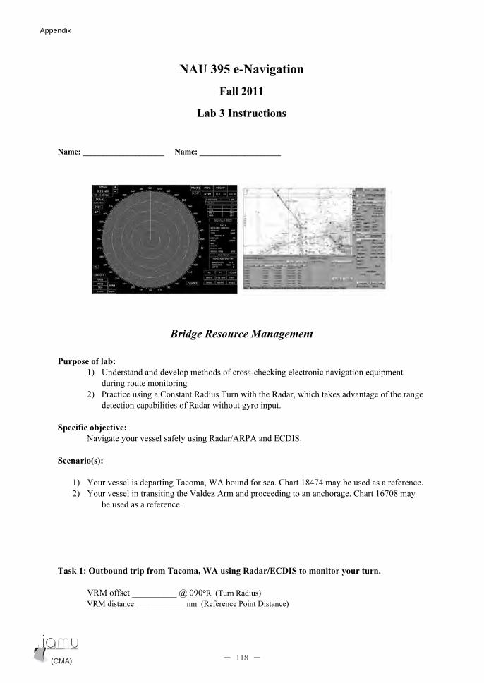
NAU 395 e-Navigation
Fall 2011
Lab 3 Instructions
Name: ____________________ Name: ____________________
Bridge Resource Management
Purpose of lab:
1) Understand and develop methods of cross-checking electronic navigation equipment
during route monitoring
2) Practice using a Constant Radius Turn with the Radar, which takes advantage of the range
detection capabilities of Radar without gyro input.
Specific objective:
Navigate your vessel safely using Radar/ARPA and ECDIS.
Scenario(s):
1) Your vessel is departing Tacoma, WA bound for sea. Chart 18474 may be used as a reference.
2) Your vessel in transiting the Valdez Arm and proceeding to an anchorage. Chart 16708 may
be used as a reference.
Task 1: Outbound trip from Tacoma, WA using Radar/ECDIS to monitor your turn.
VRM offset __________ @ 090°R (Turn Radius)
VRM distance ____________ nm (Reference Point Distance)
(CMA) (CMA)- 118 -
Appendix Appendix

Task 2: Transiting the Valdez Arm to anchorage using ECDIS/Radar to monitor your turn.
VRM offset __________ @ 090°R (Turn Radius)
VRM distance ____________ nm (Reference Point Distance)
Scenario Parameters:
The following instructions and restrictions apply to this scenario:
(1) Monitoring your turn with Radar. Use autopilot until just prior to the turn. When your
vessel is one shiplength before the turn shift to Follow-up steering and follow the radius turn
while monitoring with the VRM. Pay particular attention to hazards along the route. There
may be traffic, maintain a 1 mile CPA on large vessels and a .5 mile CPA on small vessels.
(2) Monitoring your turn with ECDIS. Use autopilot until just prior to the turn. When your
vessel is one shiplength before the turn shift to Follow-up steering and follow the ECDIS
route with radius turn. Pay particular attention to hazards along the route. There may be
traffic, maintain a 1 mile CPA on large vessels and a .5 mile CPA on small vessels.
(3) Bridge Team: Mate, Navigator, Helmsman, Lookout, and Observer
(4) The speed has been set to 13.0 knots. Maintain this speed throughout the exercises.
Vessel Characteristics:
Displacement: 37560tons
Length: 730 ft.
Beam: 75 ft.
Forward Draft: 26ft.
After Draft: 26ft.
Height of Eye: 79ft
Debrief Notes:
Question 1: When comparing the monitoring of the turns using Radar and ECIDIS, which do your feel aided in
your situational awareness the most and why?
__________________________________________________________________________________________
__________________________________________________________________________________________
__________________________________________________________________________________________
__________________
Question 2: In your own words, do you feel it is important to cross-check the electronic navigation equipment
such as Radar and ECDIS during route monitoring?
__________________________________________________________________________________________
__________________________________________________________________________________________
__________________________________________________________________________________________
(CMA) (CMA)- 119 -
Appendix Appendix

NAU 395 e-Navigation
Fall 2011
Lab 4 Instructions
Name: ____________________ Name: ____________________
Purpose of lab: Continue the use of ECDIS in route planning/monitoring, GPS in position
determination and Radar/ARPA in Collision Avoidance
Specific objectives: Integrate the use of Radar/ARPA, ECDIS, and AIS
Introduction of the Head-Up Display
Scenario(s):
1) Your vessel is inbound San Francisco bound for Martinez/Benicia. Chart 18649 may be used
as a reference.
2) Your vessel outbound San Francisco bound for sea. Chart 18649 may be used as a
reference.
(CMA) (CMA)- 120 -
Appendix Appendix

Scenario Parameters:
The following instructions and restrictions apply to this scenario:
(1) From your vessel’s position, create a route using ECDIS. Perform a route check and
revise as necessary.
Radar Setup:
Presentation mode: North UP
Pulse Length: Short
Vectors: True
Band: X-Band
Range scale: Various (3, 1.5. and .75nm)
Speed input: Nav/Log W
Parallel Index Lines:
CPA: _________nm
ECDIS Setup: Safety Values:
Safety depth - 20 M
Safety contour - 20 M
CPA - ________ NM
TCPA - 5 min
Safety vector - 5 min
Safety circle - 0.25 NM
Debrief Notes:
Answer the following questions concerning this exercise:
1) Which range scale is most useful from waypoint 1 to the Golden Gate Bridge?
________________________________________________________
2) Plot all ship targets. How do you differentiate between floating aids to navigations and ship targets?
________________________________________________________
________________________________________________________
________________________________________________________
________________________________________________________
________________________________________________________
(CMA) (CMA)- 121 -
Appendix Appendix

3) What are the advantages of using true vectors for in confined waterways such as in this exercise? What
information does relative vector provide?
________________________________________________________
________________________________________________________
________________________________________________________
________________________________________________________
(CMA) (CMA)- 122 -
Appendix Appendix
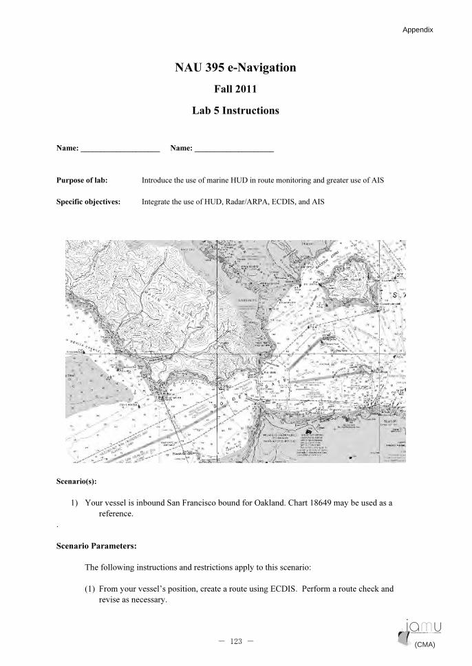
NAU 395 e-Navigation
Fall 2011
Lab 5 Instructions
Name: ____________________ Name: ____________________
Purpose of lab: Introduce the use of marine HUD in route monitoring and greater use of AIS
Specific objectives: Integrate the use of HUD, Radar/ARPA, ECDIS, and AIS
Scenario(s):
1) Your vessel is inbound San Francisco bound for Oakland. Chart 18649 may be used as a
reference.
.
Scenario Parameters:
The following instructions and restrictions apply to this scenario:
(1) From your vessel’s position, create a route using ECDIS. Perform a route check and
revise as necessary.
(CMA) (CMA)- 123 -
Appendix Appendix

(2) Pay particular attention to AIS in this exercise. Identify and confirm the information
being transmitted by both your vessel and the other vessels is correct. Notify VTS of any
discrepancies.
Radar Setup:
Presentation mode: North UP
Pulse Length: Short
Vectors: True
Band: X-Band
Range scale: Various (3, 1.5. and .75nm)
Speed input: Nav/Log W
Parallel Index Lines:
CPA: _________nm
ECDIS Setup: Safety Values:
Safety depth - 20 M
Safety contour - 20 M
CPA - ______ NM
TCPA - 5 min
Safety vector - 5 min
Safety circle - 0.25 NM
Debrief Notes:
Answer the following questions concerning this exercise:
1) In your own words, what impact could the misidentification of the vessels in and near the traffic separation
scheme have on your inbound transit?
________________________________________________________
________________________________________________________
__________________________________________________
2) Plot all ship targets using the Radar/ARPA. How do you differentiate between floating aids to navigations
and ship targets?
________________________________________________________
________________________________________________________
________________________________________________________
________________________________________________________
______________________________________________
(CMA) (CMA)- 124 -
Appendix Appendix

3) What are the advantages of using true vectors for in confined waterways such as in this exercise? What
information does relative vector provide?
________________________________________________________
________________________________________________________
________________________________________________________
________________________________________________
4) What are the limitations of the information provided by AIS?
________________________________________________________
________________________________________________________
________________________________________________________
________________________________________________
(CMA) (CMA)- 125 -
Appendix Appendix

1
NAU 395 e-Navigation
Fall 2011
Lab 8 Instructions
Purpose of lab:
Learn proper procedures of ship-to-ship and ship-to-shore communication
while safely navigating a vessel within a mandatory Vessel Traffic Service (VTS) area. This
lab will look at how mandatory VTS can both impact and influence vessel movement into and
out of a large port.
Specific objectives:
(1) Navigate safely by complying with vessel control orders issued by VTS
(2) Communicate effectively by VHF/AIS Text Messaging with VTS and other vessels in
system
(3) Determine if and when it might be necessary to deviate from VTS controlled maneuvers
(CMA) (CMA)- 126 -
Appendix Appendix

2
Scenario: Six separate ownships transiting in and out of Los Angeles/Long Beach Harbor
Ownship numbers, names and destinations:
1) Petrochem Express (tanker) – outbound for San Francisco
2) Catalina (fast ferry) – outbound for Avalon Harbor, Catalina Island
3) CSX Baltimore (containership) – outbound for New Orleans via Panama Canal
4) LNG Aquarius (LNG tanker) – inbound for inner anchorage area B-8
5) Newport Beach (fast ferry) – inbound for Berth 93A San Pedro
6) Cadillac (bulk carrier) – inbound for Pier 300, Berth 301
Vessel particulars:
See vessel characteristics information on conning display
Environment:
Time: 1630, 9 November 11
Visibility: good
Sea conditions: moderate chop, Beaufort Force 4
Traffic:
Mandatory VTS vessel control situation is in effect by order of the Captain of the Port of Los
Angeles/Long Beach
Call VTS (“San Pedro Traffic”) on Ch. 13/ AIS Text Messaging for traffic report and:
1 – getting underway outbound
2 – passing through breakwater
3 – departing or entering precautionary area
4 – arriving at destination inbound
When first contacting traffic before getting underway, give vessel name and call sign, deep draft, and
destination. Request that VTS load a preferred route for the conning officer to inspect prior to getting
underway. Once the route is loaded into ECDIS and approved by conning officer, request permission
from VTS to get underway. VTS may permit the routes of other vessels to be displayed on your ECDIS.
Route
Follow the route provided by VTS unless deviation is necessary for collision avoidance or the route is
deemed unsafe for any reason. Inform VTS immediately of any deviation from the route.
Night Orders:
Keep a 0.2 mi CPA on all contacts unless meeting or overtaking other vessels.
Use no more than 15 knots when inside precautionary area, 8 knots inside breakwater.
(CMA) (CMA)- 127 -
Appendix Appendix

3
Make certain running lights are on.
Sound fog signal if visibility drops below 1 mile.
Call all other vessels by VHF Ch 13/AIS Text Messaging if crossing, overtaking or meeting within 1
mile
Bridge Team:
Conning Officer, Radar, Navigator (ECDIS), Helmsman (con)
VTS Standing Orders for Mandatory Vessel Control Situations:
1) Maintain a constant radio watch on VHF Ch. 13
2) Answer VTS immediately when hailed
3) Comply immediately with any VTS order to change course or speed
4) Hail other vessels on VHF Ch. 13 for meeting agreements unless already specified by VTS
Bridge teams: Watch Officer, Helmsman, and Lookout
Notes:
1. Only the team leader may talk on the radio.
2. Listen for an open channel before you begin your radio calls. Do not talk over other vessels or VTS.
3. A professional demeanor on the radio and AIS Text Messaging must be maintained at all times.
4. This likely to be a very difficult scenario that will require you to listen to the radio at all times and carry out
the orders of VTS to the best of your ability.
(CMA) (CMA)- 128 -
Appendix Appendix
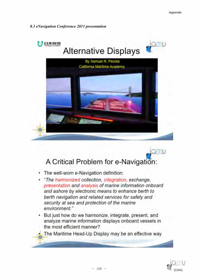
8.3 eNavigation Conference 2011 presentation
(CMA) (CMA)- 129 -
Appendix Appendix
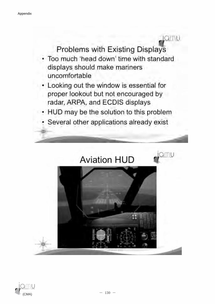
(CMA) (CMA)- 130 -
Appendix Appendix

(CMA) (CMA)- 131 -
Appendix Appendix
(CMA) (CMA)- 132 -
Appendix Appendix
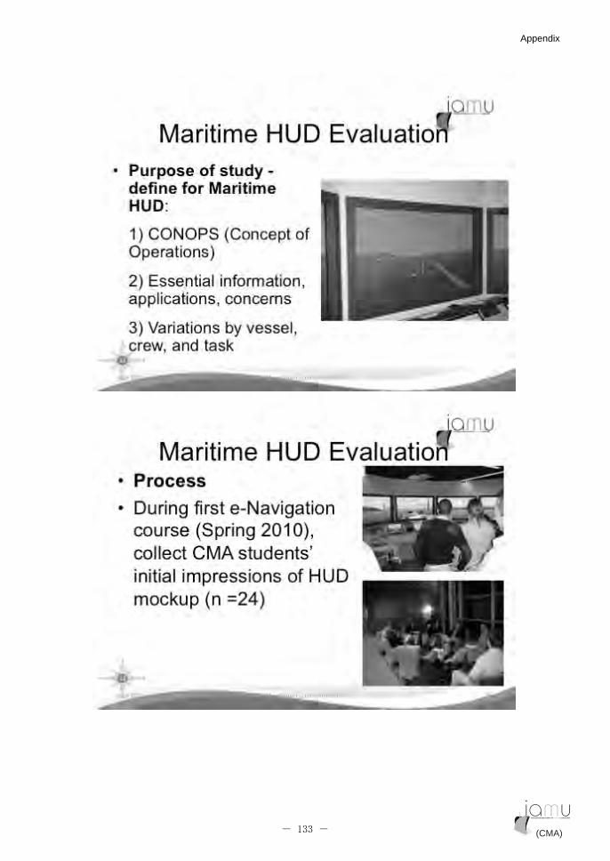
(CMA) (CMA)- 133 -
Appendix Appendix

(CMA) (CMA)- 134 -
Appendix Appendix

(CMA) (CMA)- 135 -
Appendix Appendix
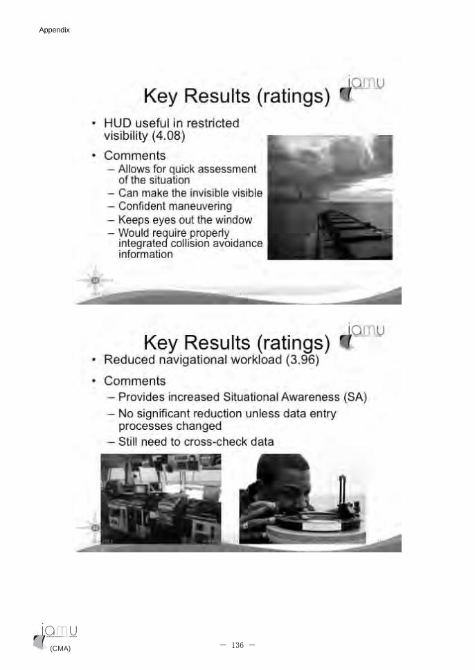
(CMA) (CMA)- 136 -
Appendix Appendix
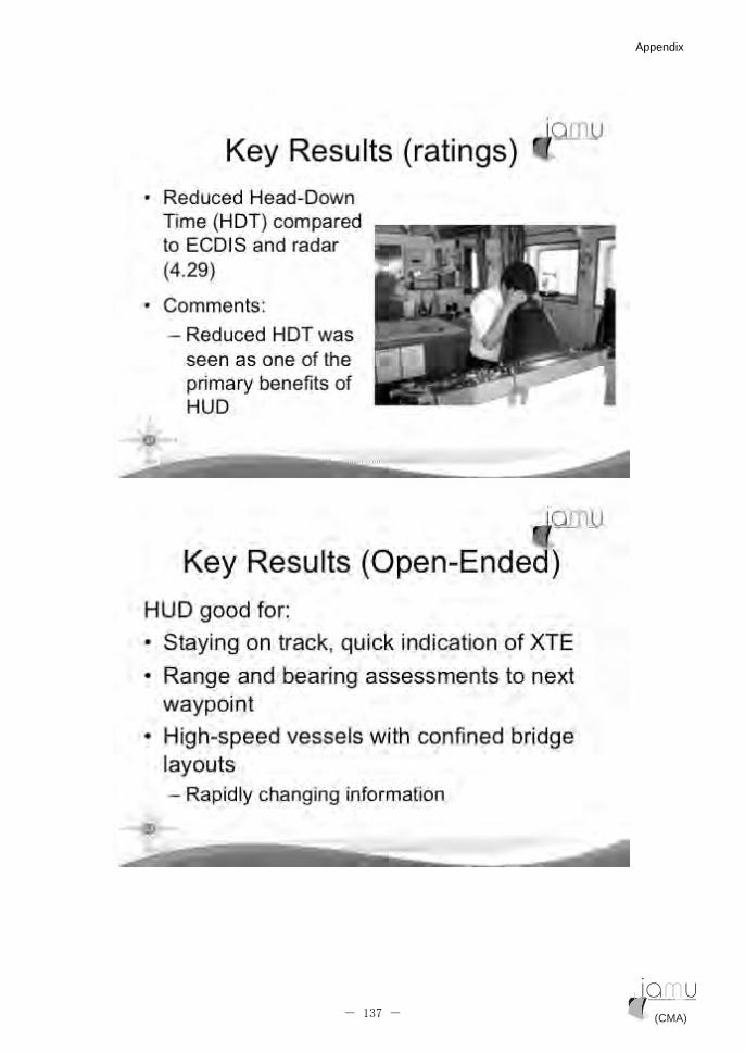
(CMA) (CMA)- 137 -
Appendix Appendix

(CMA) (CMA)- 138 -
Appendix Appendix

(CMA) (CMA)- 139 -
Appendix Appendix

(CMA) (CMA)- 140 -
Appendix Appendix
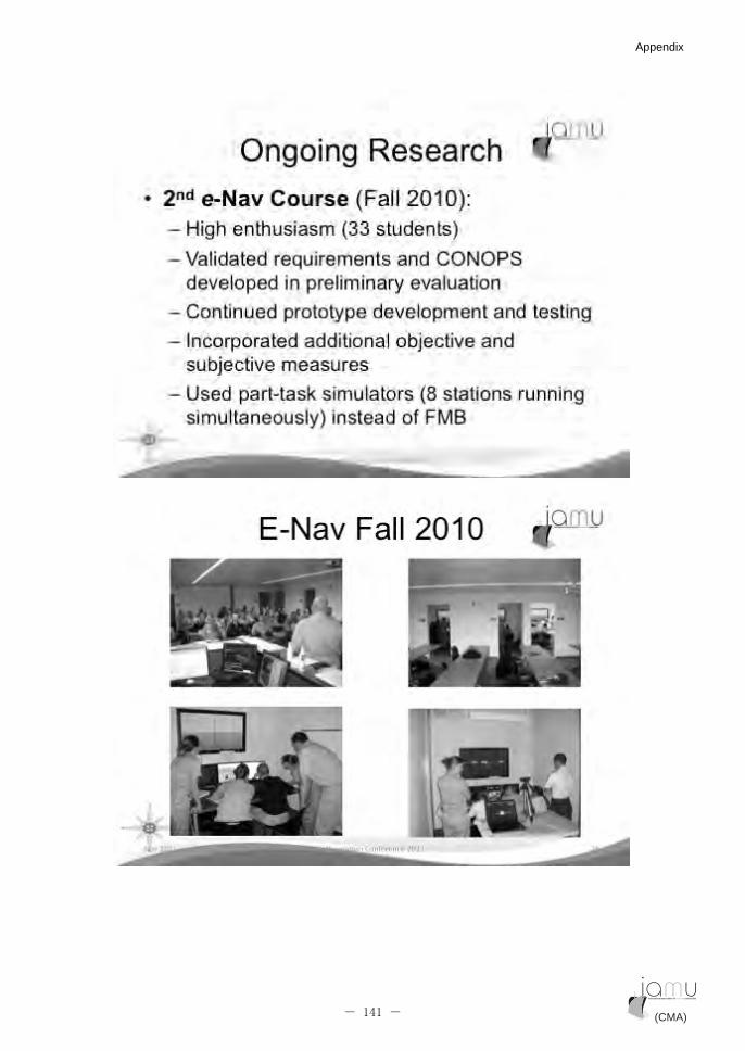
(CMA) (CMA)- 141 -
Appendix Appendix
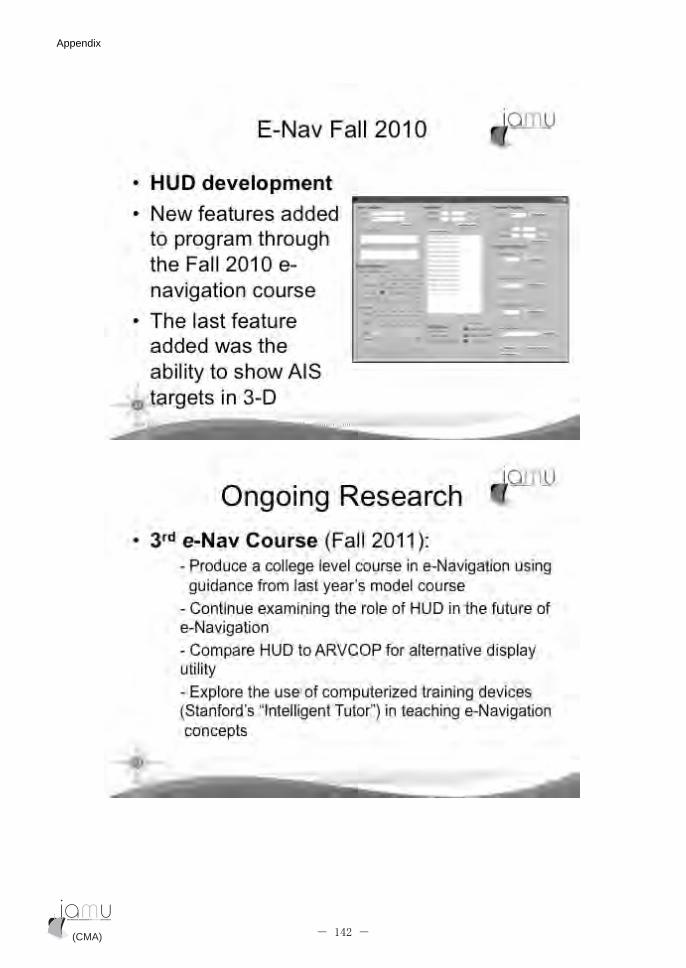
(CMA) (CMA)- 142 -
Appendix Appendix
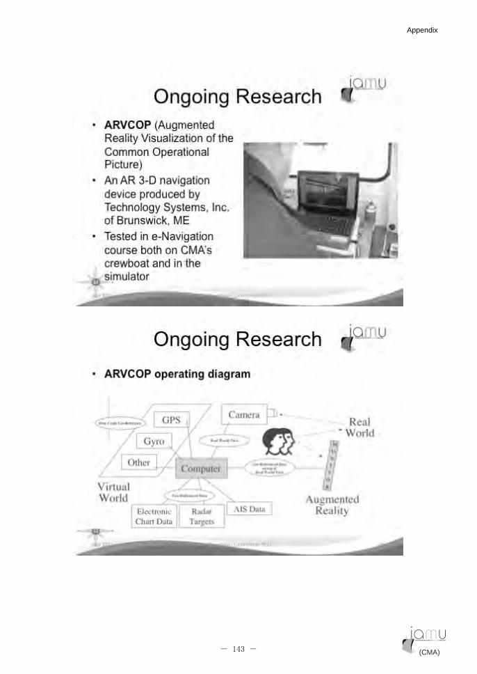
(CMA) (CMA)- 143 -
Appendix Appendix
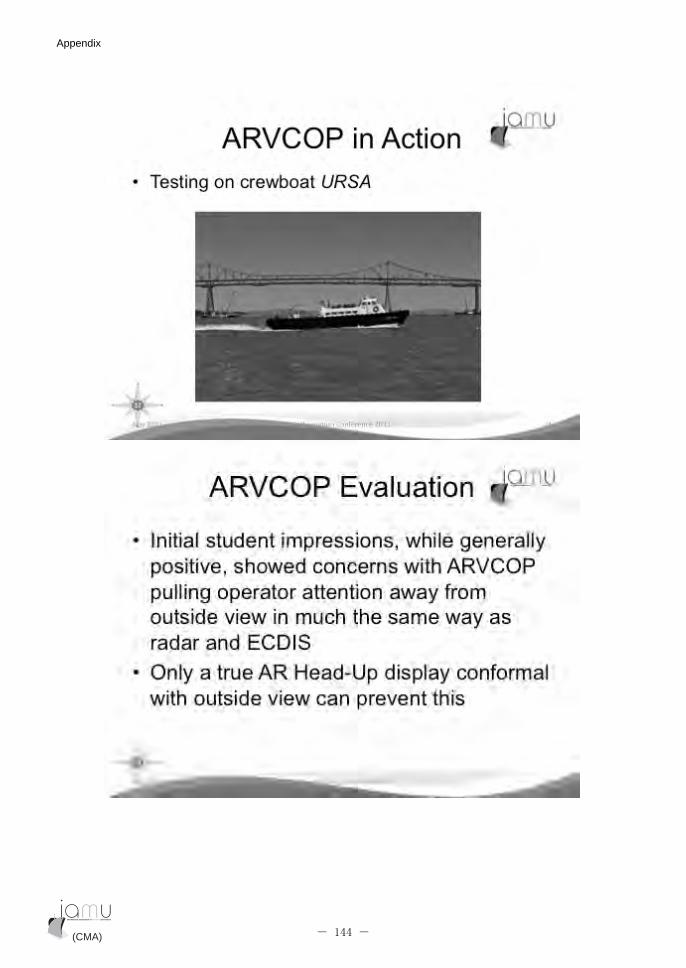
(CMA) (CMA)- 144 -
Appendix Appendix
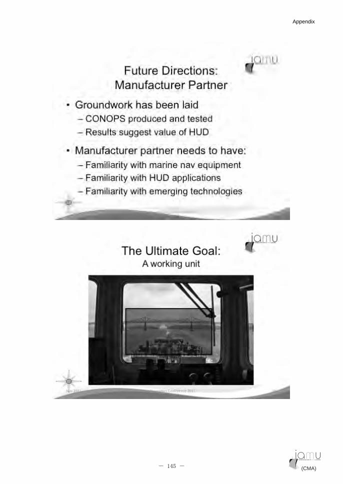
(CMA) (CMA)- 145 -
Appendix Appendix

(CMA) (CMA)- 146 -
Appendix Appendix

(CMA) (CMA)- 147 -
Appendix Appendix

�
(CMA) (CMA)- 148 -
Appendix Appendix
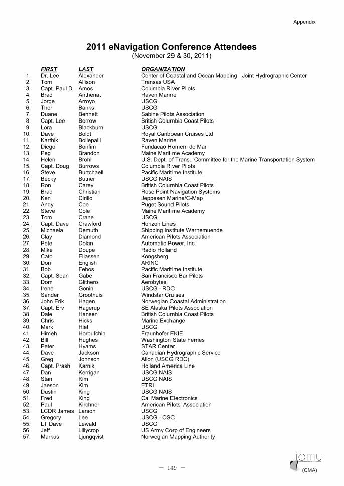
2011 eNavigation Conference Attendees (November 29 & 30, 2011)
FIRST LAST ORGANIZATION1. Dr. Lee Alexander Center of Coastal and Ocean Mapping - Joint Hydrographic Center 2. Tom Allison Transas USA 3. Capt. Paul D. Amos Columbia River Pilots 4. Brad Anthenat Raven Marine 5. Jorge Arroyo USCG 6. Thor Banks USCG 7. Duane Bennett Sabine Pilots Association 8. Capt. Lee Berrow British Columbia Coast Pilots 9. Lora Blackburn USCG
10. Dave Boldt Royal Caribbean Cruises Ltd 11. Karthik Bollepalli Raven Marine 12. Diego Bonfim Fundacao Homem do Mar 13. Peg Brandon Maine Maritime Academy 14. Helen Brohl U.S. Dept. of Trans., Committee for the Marine Transportation System 15. Capt. Doug Burrows Columbia River Pilots 16. Steve Burtchaell Pacific Maritime Institute 17. Becky Butner USCG NAIS 18. Ron Carey British Columbia Coast Pilots 19. Brad Christian Rose Point Navigation Systems 20. Ken Cirillo Jeppesen Marine/C-Map 21. Andy Coe Puget Sound Pilots 22. Steve Cole Maine Maritime Academy 23. Tom Crane USCG 24. Capt. Dave Crawford Horizon Lines 25. Michaela Demuth Shipping Institute Warnemuende 26. Clay Diamond American Pilots Association 27. Pete Dolan Automatic Power, Inc. 28. Mike Doupe Radio Holland 29. Cato Eliassen Kongsberg 30. Don English ARINC 31. Bob Febos Pacific Maritime Institute 32. Capt. Sean Gabe San Francisco Bar Pilots 33. Dom Glithero Aerobytes 34. Irene Gonin USCG - RDC 35. Sander Groothuis Windstar Cruises 36. John Erik Hagen Norwegian Coastal Administration 37. Capt. Erv Hagerup SE Alaska Pilots Association 38. Dale Hansen British Columbia Coast Pilots 39. Chris Hicks Marine Exchange 40. Mark Hiet USCG 41. Himeh Horoufchin Fraunhofer FKIE 42. Bill Hughes Washington State Ferries 43. Peter Hyams STAR Center 44. Dave Jackson Canadian Hydrographic Service 45. Greg Johnson Alion (USCG RDC) 46. Capt. Prash Karnik Holland America Line 47. Dan Kerrigan USCG NAIS 48. Stan Kim USCG NAIS 49. Jaeson Kim ETRI 50. Dustin King USCG NAIS 51. Fred King Cal Marine Electronics 52. Paul Kirchner American Pilots' Association 53. LCDR James Larson USCG 54. Gregory Lee USCG - OSC 55. LT Dave Lewald USCG 56. Jeff Lillycrop US Army Corp of Engineers 57. Markus Ljungqvist Norwegian Mapping Authority
(CMA) (CMA)- 149 -
Appendix Appendix

2011 eNavigation Conference Attendees Page 2 of 2
FIRST LAST ORGANIZATION58. Jeff Lynch USCG 59. David Marjoribanks Fraser River Pilots 60. Capt. Ed Marmol Puget Sound Pilots 61. Kevin Martin Aerobytes 62. Mike McBrady USCG 63. Kevin Miller USCG 64. Ben Minichino CLS America 65. Soo Jong Mo MEIPA 66. Capt. Bob Moore Conference Co-Chair 67. Mike Morris Houston Pilots 68. Doug Morrison Cartel Communication Systems, Inc. 69. Florian Motz Research Establishment for Applied Science 70. Reinhard Mueller Shipping Institute Warnemuende 71. Robert Page USCG 72. Su Hyun Park 73. Capt. Sam Pecota California Maritime Academy 74. Capt. Simon Pelletier Canadian Marine Pilots Association 75. Ken Pike Seaspan Marine 76. Cesar Pimenta Fundacao Homem do Mar 77. Barry Poole Seaspan Marine 78. Fred Pot Conference Co-Chair 79. LT Larry Prewitt USCG 80. Bill Rall UW School of Oceanography 81. Darryl Randolph USCG 82. Sumita Roy Maritime Services Ltd. 83. Tom Rutter Virginia Pilots' Association 84. Capt. Victor Schisler California Maritime Academy 85. Pankaj Sharma Institute for Infocomm Research, Singapore 86. Mike Sollosi USCG & IMO Subcommittee on the Safety of Navigation 87. Doug Sowdon Washington State Ferries 88. Paul Stanley Navicom Dynamics Ltd. 89. Sang Hyun Suh KORDI 90. RADM Keith Taylor USCG 91. Brian Tetreault ERDC/Coastal & Hydraulics Lab 92. Adam Tucker Royal Caribbean Cruises Ltd 93. Kevin Vail Canadian Marine Pilots Association 94. Alan Weigel Blank Rome 95. Bob Whetsell Aerobytes 96. Mike Young British Columbia Coast Pilots
(CMA) (CMA)- 150 -
Appendix Appendix
8.4 List of all sources used for the e-Navigation research project
Bole, Alan, Bill Dineley and Alan Wall. Radar and ARPA Manual, 2nd
Ed. Oxford: Elsevier
Butterworth-Heinemann, 2005.
Buckley, James J. and Samuel R. Pecota, “Integration of ECDIS in bridge simulation courses: Are
there performance or perception differences?” INSLC, St. Johns, Newfoundland, Canada, July
2008.
Buckley, James J. and Samuel R. Pecota, “New Technology and BTM,” Seaways, August 2008.
Buckley, James and Samuel R. Pecota, “Practiced-based learning: Exploiting new technologies,”
Maritime Transport Conference, Barcelona, Spain, April 2009.
Chakraborty, Devbrat, IMO’s e-Navigation Project: Current Status, National Maritime Foundation, 26
Aug 2009.
Coleman, David, Samuel R. Pecota, James J. Buckley, and Steven Browne, “The use of marine
simulators in developing the concepts and technology of e-Navigation,” INSLC, Pusan, Korea,
July 2010.
Fuechel, Jack and Robert Markle, Conclusions of the 20 May 2010 GMDSS Modernization Workshop,
GMDSS Taskforce Modernization Notes.
Hecht, Berking, et. Al. The Electronic Chart, 2nd
ed. Lemmer: GITC, 2006.
IALA e-Navigation Committee Frequently Asked Questions (Version 1.5 dated September 2010.
IMO Model Course 1.27 Operational Use of ECDIS.
IMO Model Course 1.32 Operational Use of Integrated Bridge Systems.
IMO Model Course 1.34 Automatic Identification Systems.
MSC 81/23/10, Development of an E-Navigation strategy, 19 December 2005.
MSC 85/26/Add.1, Annex 20, Strategy for the Development and Implementation of e-Navigation,
2008.
MSC.191(79), Annex 33, Performance Standards for the Presentation of Navigation-Related
Information on Shipborne Navigation Displays, 6 Dec 2004.
MSC.232(82), Adoption of the Revised Performance Standards for ECDIS, 5 Dec 2006.
MSC.64(67), Annex 1, Recommendation on Performance Standards for Integrated Bridge Systems
(IBS), 1996.
MSC.74(69), Annex 3, Recommendations on Performance Standards for a Universal Shipborne
Automatic Identification System (AIS), 1998.
MSC.86(70), Annex 3, Recommendation on Performance Standards for an Integrated Navigation
System (INS), 1998.
MSC.Circ.1061, Guidance for the Operational Use of Integrated Bridge Systems (IBS), 3 Jan 2003.
NAV 55/WP.5, Development of an e-Navigation Strategy Implementation Plan, 29 July 2009.
Norris, Andy. ECDIS and Positioning. London: The Nautical Institute, 2010.
Norris, Andy. Radar and AIS. London: The Nautical Institute, 2008.
Patraiko, David, Introducing the e-navigation revolution, The Nautical Institute, 2007.
Pecota, Samuel R. Radar Observer Manual. Houma: Marine Education Textbooks, 2006.
Pecota, Samuel R. and James J. Buckley, “Training paradigm assisted accidents: Are we setting our
students up for failure?” IAMU AGA10, St. Petersburg, Russia, September, 2009.
Pecota, Samuel R. and James J. Buckley, “New Technology Demands Maritime Education Reform,”
Pacific Maritime Magazine, December 2009.
Pillich, Bohdan, Developing e-Navigation, the early stages, BMT Ports and Logistics, 2007.
Resolution A.857 (20), Guidelines for Vessel Traffic Services, 27 November 1997.
Resolution A.917(22), Guidelines for the On-Board Operational Use of Shipborne Automatic
Identification Systems (AIS).
SharpEye White Paper. Promotional pamphlet for new solid-state radar produced by Kelvin Hughes
Company, 2009.
(CMA) (CMA)- 151 -
Appendix Appendix

Swift, A.J. and T.J. Bailey. Bridge Team Management: A Practical Guide, 2nd
Ed. London: The
Nautical Institute, 2004.
The EfficienSea Project, DaMSA, 2007-2013, information PowerPoint.
Ward, Nick, The IMO e-Navigation Initiative, Research & Radionavigation, General Lighthouse
Authorities, UK and Ireland, 2009.
Weintrit, Adam. The Electronic Chart Display and Information System (ECDIS): An Operational
Handbook. London: CRC Press, 2009.
(CMA) (CMA)- 152 -
Appendix Appendix