Embed Size (px)
Citation preview

IAEA Meeting, Nov. 2008
F.P. Glasser
“Cements in Radioactive Waste
Disposal”

Role of cement
Portland cement has a dual role:• Structural, to provide physical support for repository construction, containers for storage and transportation; also shielding• Matrix former and conditioning agent to reduce solubility and mobility of radionuclides, exclude aggressive chemicals from the environment and protect steel against corrosion, etc
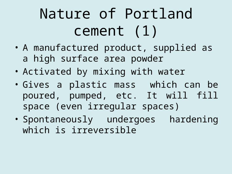
Nature of Portland cement (1)
• A manufactured product, supplied as a high surface area powder
• Activated by mixing with water• Gives a plastic mass which can be poured,
pumped, etc. It will fill space (even irregular spaces)
• Spontaneously undergoes hardening which is irreversible
Nature of Portland Cement (2)
• Modern Portland cement patented about 1824. Current production is in excess of 2•10 exp 9 tonnes/yr
• Product is made to specification: broadly similar worldwide
• Product composition and specification are changing slowly and will continue to change

Microstructure
Portland cement (3)
Has two disadvantages you need to know• When mixed with water, evolves 200-350 KJ/kg
heat in first 7 days• As the initial plastic mass hardens, it shrinks
(specific volume of hydrates is less than that of anhydrous powder + mix water)
• These much affect scale- up, from lab to full scale

Heat evolution
400
300
200
100
0 24 48 72 96 120 144Time, hrs, from mixing Portland cement and water
I
III
IIIIV
Inst
anta
neo
us h
eat r
elea
se (
arb
i trar
y un
i ts)
Cum
ulative hea
t release
, kJ/kg

Managing Heat Evolution
• Use forced cooling• Use special low- heat- of hydration cement• Replace part of the cement with
supplementary cementing materials (slag, fly ash). N.B. : this strategy is not always successful!
• Dilute cement with mineral aggregate• Control maximum size/ geometry of pour
and delay sequential pours

Managing shrinkage-1
• Accept that shrinkage has two main contributions; thermal and chemical.
• Chemical shrinkage arises from the volume relationships between reactants and products
• Thermal shrinkage results from normal coefficient of dilation (cement is comparable with steel)

Managing shrinkage-2
• Use expansion joints (not usually acceptable in nuclear constructions)
• Use shrinkage- reducing (SR) admixes (organic SR’s may not be acceptable; inorganic systems are difficult to control)
• Provide restraint. (Steel helps control chemical shrinkage but does not deal well with thermal). Experience needed for correct design at corners, edges, etc

Managing shrinkage -3
• Adding inert mineral aggregate is almost universal
• Aggregate acts as a heat sink• Properly graded aggregates reduce
cement contents to 275-400kg/m³ without undue loss of strength
• Wide choice of aggregates available but preferably, select inert and low- permeability rock types

Matrix porosity and permeability-1
• Relation between porosity and permeability is complex but broadly, low porosity gives low permeability. However once porosity exceeds 6-10%, pores increasingly interconnect and permeability decreases rapidly
• Water in excess of that required to hydrate cement remains as water- filled pores

Matrix P. and P.-(2)
• In practice, the water demand expressed as a water; cement weight ratio (w/c) is about 0.30 to 0.36 for complete hydration: a benchmark value!
• But low w/c ratios may give too stiff a product to emplace, so “practical” w/c ratios lie in the range 0.48-0.65 (for concrete).
• Lower ratios can be achieved by using plasticisers – water- dispersible organic high polymers- which act as lubricants
• Their use should not be rejected without careful analysis of the benefit: addition is usually low, <1%.

Physical Barrier Formation
• Concrete can be vibrated into shape but vibration is tricky to handle; over- vibration leads to segregation and laitance, etc
• Self- compacting concretes (SCC) have radically altered the commercial situation
• SCC is based on Portland cement, partly replaced by finely ground limestone and made to low w/c ratios using a plasticiser
• Again, benefits of SCC should always make it a candidate for physical barrier formation
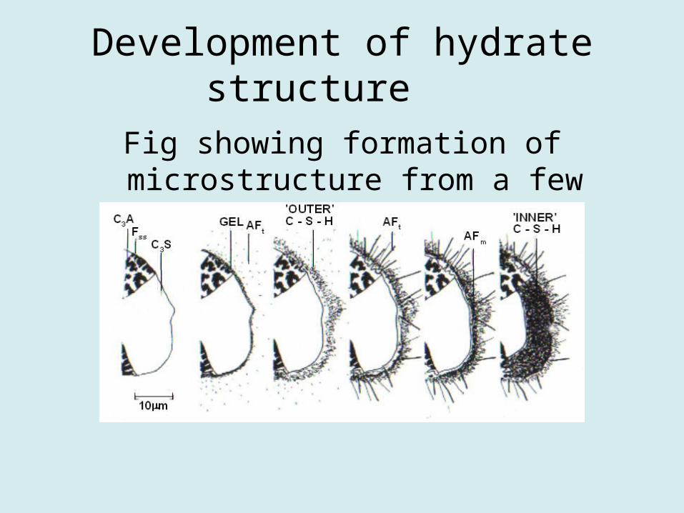
Development of hydrate structure
Fig showing formation of microstructure from a few minutes to a few days

Internal Chemistry-1
• The pH is controlled initially by solubility of alkalis (Na, K) in pore fluid.
• These give pH in excess of 12.5• However alkalis are not well retained and
once leached, pH is controlled by Ca(OH)2, to about 12.5. Many P.A.’s start at this point
• The pH is well buffered initially by 20- 25% portlandite
Internal Chemistry-2
• The Eh function (redox potential reflects the lack of poising couples (the Eh equivalent of buffering) and the slightly oxidising conditions obtaining during manufacture
• As a result, Eh is about +100 to + 200MV• Active redox couples readily affect this
numerical value- slag, containing sulfide sulfur, lowers it to -400MV

Internal Chemistry
• But the measurements of Eh and poising capacity are far from being well understood
• Many potential couples, eg presence of spinel, gaseous hydrogen, are inert over at least the first years. Importance of kinetics

Interaction of Cement with Waste Species
Until recently, little attempt was made to distinguish nature of binding mechanisms- all were termed “sorption”.
This has led to great uncertainties over numerical values and apparently significant concentration dependence on the numerical values. Also, reversibility has not usually been established

Proposal
Four states of evolution of cements are suggested for benchmarking. These are:
Stage I. The pH is dominated by alkali. All normal cement mineral hydrates are present
Stage 2. The pH is dominated by Ca(OH)2. All normal hydrates are present
Stage 3 .Ca(OH)2 consumed: C-S-H, depending on composition, buffers pH in the range 10 to 12
Stage 4. Only degradation and reaction products left to condition pH.

Suggested approach
The four- stage approach has been used in Belgian assessment for assessment of the performance of the low-level repository at Dessels (in advancd planning stage). Data and methodology with Rd (or Kd) values for each stage is expected to be published in early 2009 (by ONDRAF).
Processes
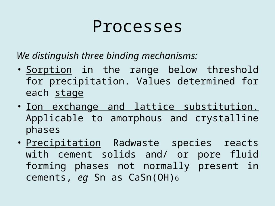
We distinguish three binding mechanisms:• Sorption in the range below threshold for
precipitation. Values determined for each stage• Ion exchange and lattice substitution. Applicable
to amorphous and crystalline phases• Precipitation Radwaste species reacts with
cement solids and/ or pore fluid forming phases not normally present in cements, eg Sn as CaSn(OH)6

Specific Degradation Mechanisms
• Engineers have long categorised deterioration into specific modes, eg sulfate attack, carbonate attack. To this must be added alkali- aggregate attack because many concrete aggregates are NOT inert
• The criteria for recognition and mitigation often rest on empirical criteria

Example: Alkali- Aggregate
Aggregates known to cause problems include those with:
• amorphous (or low crystallinity) quartz, opal tridymite, cristobalite; also, strained quartz
• Dolomite, CaMg(CO3)2 • Altered basalts with layer lattice minerals
susceptible to ion exchangeClearly, a number of different mechanisms must
operate. But expansive damage may not be apparent for months, years or decades
Avoidance and Mitigation of AAR
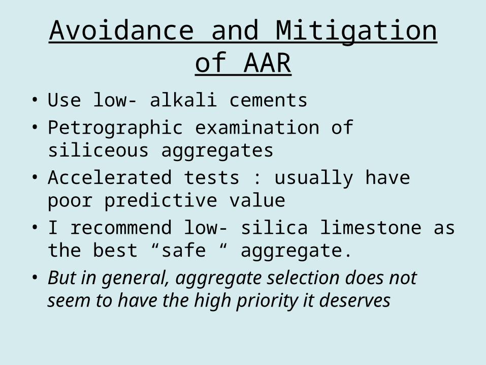
• Use low- alkali cements• Petrographic examination of siliceous
aggregates• Accelerated tests : usually have poor predictive
value• I recommend low- silica limestone as the best
“safe “ aggregate. • But in general, aggregate selection does not
seem to have the high priority it deserves

Progress in understanding alteration
I use carbon dioxide as an example.
• We need to consider two forms: gaseous CO2 and aqueous CO2.
• The action of CO2 gas is straightforward
• Dissolved CO2 is more complex: depending on pH and speciation, its action can be corrosive, neutral or protective.
Gaseous carbon dioxide
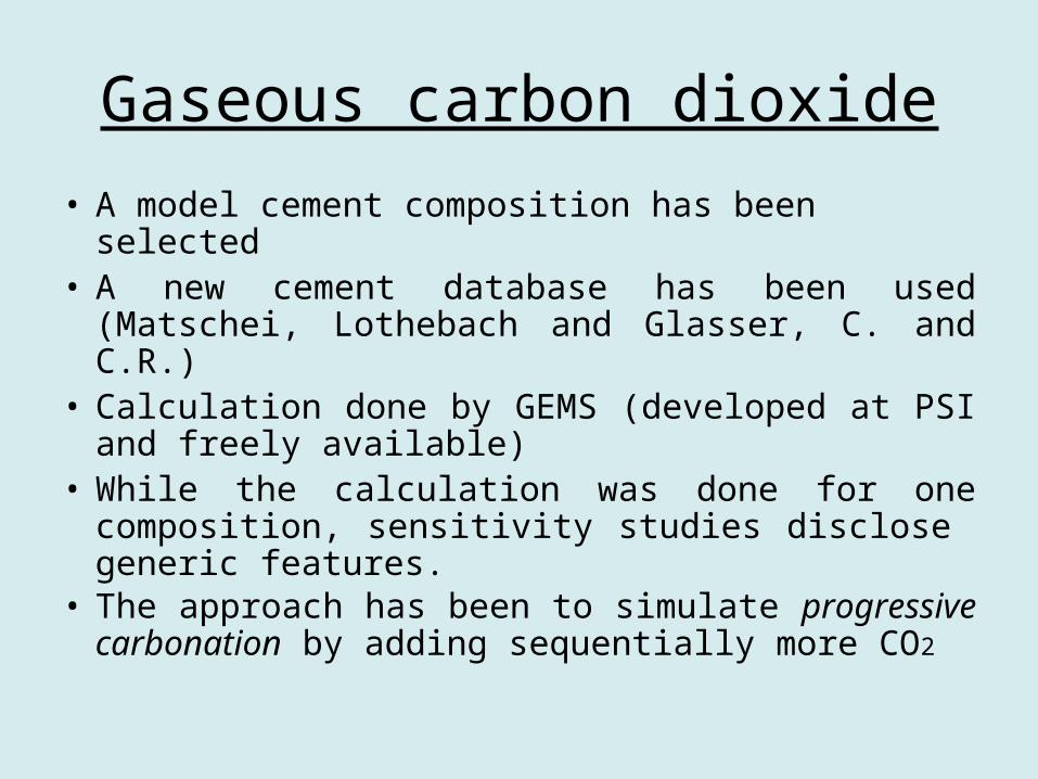
• A model cement composition has been selected• A new cement database has been used
(Matschei, Lothebach and Glasser, C. and C.R.)• Calculation done by GEMS (developed at PSI
and freely available)• While the calculation was done for one
composition, sensitivity studies disclose generic features.
• The approach has been to simulate progressive carbonation by adding sequentially more CO2

ResultsCalculation of zonation in the course of carbonation
0
20
40
60
80
100
120
140
0 10 20 30 40 50 60
CO2 addition [g/100g cement]
solid
s [g
/100
g c
emen
t]
calcite
C-S-H (Ca/Si const. ~ 1.6)
C-S-H (Ca/Si decreasing)
SiO2
(amorphous)thaumasite
Al(OH)3
monocarboaluminate
ettringite
portlandite
stratlingite
I II (portlandite carbonation) (carbonation of remaining hydrates including C-S-H)III
(fully car- bonated)IV
gypsum
Ca/Si~1.6 pH (constant) ~ 12.5 Ca/Si~1.6 -> ~0.8 pH (decreasing) ~ 12.5 -> ~10
Ca/Si (const)~0.8 pH ~ 10
pH ~ 7.7
Carbonation is a very complex process

Early stages of carbonation
0
20
40
60
80
0 1 2
CO2 addition [g/100g cement]
solid
s [g
/100
g ce
men
t]
monocarboaluminate
ettringite
calcite
hemicarbo-aluminate
monosulfoaluminate
portlandite
C-S-H (Ca/Si const. ~ 1.6)
Ia Ib IIVolume changes
0.0 0.5 1.0 1.5 2.00
20
40
60
80
tota
l vol
ume
[cm
3]
CO2 addition [g/100g cement]
CSHII CH monosulfate calcite Mc Hc AFt CSHI silica AlOH3 thaumasite gypsum stratlingite
calcite
excess pore solution
monocarboal.hemicarb.monosulfoal.
portlandite
C-S-H (Ca/Si ~ 1.6)
AFt
The early stages may be achieved by „normal“ Portland cement which contains small amounts of carbonate, sufficient partly to prevent formation of monosulfoaluminate

Volume changes due to carbonation
0 10 20 30 40 50 600
20
40
60
80
100
120to
tal v
olum
e [c
m3 ]
CO2 addition [g/100g cement]
monosulfate calcite Mc Hc AFt CH CSHI CSHII silica AlOH3 thaumasite gypsum stratlingite
calcite
excess water
stratlingitethaumasite
Al(OH)3
SiO2 (am)
gypsum
ettringiteportlandite
monocarb.
I II (portlandite carbonation) (carbonation of remaining hydrates including C-S-H)
(fully car- bonated)III IV
Space filling effect due to carbonation and densification of cement paste
Aqueous Carbon Dioxide
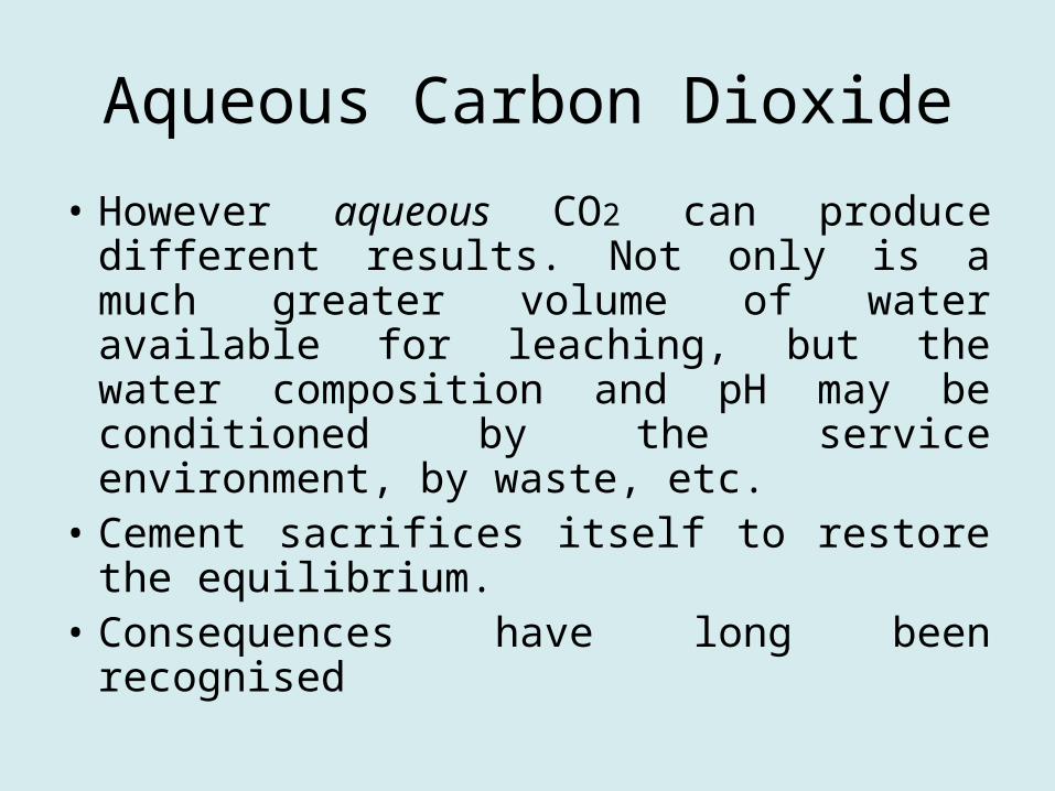
• However aqueous CO2 can produce different results. Not only is a much greater volume of water available for leaching, but the water composition and pH may be conditioned by the service environment, by waste, etc.
• Cement sacrifices itself to restore the equilibrium.
• Consequences have long been recognised

Empirical CO2 diagram
Aggressive CO2 vs bicarbonate

Computer based calculation
• System CaO- CO2-H2O at 25ºC
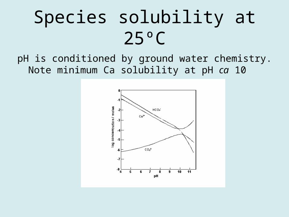
Species solubility at 25ºC
pH is conditioned by ground water chemistry. Note minimum Ca solubility at pH ca 10

Summary (1)
• I have covered a lot of ground rather thinly
• Cement science is in transition, between qualitative and quantitative
• For the time being, we have to get by with a mixture of approaches
• Nuclear waste management badly needs quantitative approaches, given time scales for performance

Summary (2)
• I do not see commercial advantage accruing and therefore urge an international cooperative approach
• Confidence in waste disposal remains an important ”show stopper” in the public and legislative acceptance of nuclear waste- hence the importance of quantification of performance.