Embed Size (px)
Citation preview
T O R Q U E R E D U C T I O N
NINE TO 11 km reach world-class ERDwells are used in the Russian Far East todevelop an offshore reservoir from anonshore location. While drilling initialwells into the reservoir, high torque wasexperienced, even while using a non-aqueous drilling fluid. The torque wassufficiently high that concerns aroseabout the feasibility to drill longer wells.Consequently, finding techniques toreduce drilling torque became a majorfocus for the development.
A systematic R&D process was initiatedto solve the torque problem. The scope ofthe investigations included considerationof different base oils, solid/liquid lubri-cants and mechanical means to reducetorque. Small-scale screening lubricitytesting was performed in a controlledlaboratory environment to identifypotential lubricant candidates. Full-sizedlaboratory testing was then performedon the leading products. Variousmechanical means to reduce torque werealso evaluated. Finally, field trials wereperformed using solid and liquid lubri-cants and different types of mechanicaltorque reduction tools.
Solid lubricants caused issues with BHAcomponents and their use was discontin-ued. Liquid lubricants achieved torquereductions of 5 percent to 15 percent,which was sufficient to drill the longestthrow wells. The mechanical tools addedto the drillstring were found to havedrawbacks related to the durability ofthe tools or the achieved torque reduc-tion. Both mechanical and lubricant solu-tions represented a significant additionto the overall cost of the wells. Eventual-ly, the use of 4,500 m range II drillpipecaused an immediate 30 percent to 35percent drop in torque. Further evidencethat the large contact area between thecasing and the range III drillpipe is caus-ing both excessive wear and torque wasprovided when DP inspections revealedan alarming increase in rejections due toexcessive tube wear.
Ongoing investigations attempt to findmechanical solutions to the drillpipe cas-ing contact problem. While new orders ofdrillpipe will be range II pipe, the exist-ing large inventory of range III drillpipeneeds to be protected from excessivewear, while at the same time reducingthe drilling torque. Several types of DP
centralizers are under investigation andmay represent a viable solution to bothproblems.
Torque Reduction Techniques in ERDWells (IADC/SPE 98969) JH Schamp, BLEstes, SR Keller, WJ Thomas, ExxonMo-bil.
C A T E N A R Y W E L L P R O F I L E
This paper presents analysis and designof ultra-long wells using a catenary wellprofile.
The paper presents results from aresearch program that was undertakento define the limits and the potential forultra-long wells. A major part of theresearch is the development of a com-plete catenary model for design of well-path, drill pipe loads and torque anddrag forces. The new model is analytical-ly exact, but it is simplified by replacingthe hyperbolic functions with ordinarytrigonometric functions. The paper willpresent a procedure to compute the wellpath and forces, in addition to a workedexample of a catenary well, such thatanyone can construct these wellpathsusing a spreadsheet.
Standard and undersection build profilesare compared with several catenary pro-files. It is shown that the only way to limitthe torque is by applying a catenary pro-file. Furthermore, various well opera-tions are investigated. Ten, 12 and 16 kmhorizontal departure wells are com-pared. One of the findings is that there isan optimum length and shape of the cate-nary from the kick-off point to the sailsection, where well friction is at a mini-mum.
The study shows that a 16 km horizontaldeparture well can be drilled with ordi-nary drillpipes by using a catenary pro-file. A comparison with other pipe mate-rials is provided.
Other limitations to ultra-long wells arealso addressed, such as hydraulics, cas-ing seat location and borehole stabilityissues. The paper presents a proposeddrill string design for ultra-long wells.
The proposed paper is significant for theevolution of ultra-long wells. The com-plete method basis for the catenary is notpublished earlier, and, with the workedexamples, it will provide an importanttool to plan these wells.
Construction of Ultralong Wells Usinga Catenary Well Profile (IADC/SPE98890) BS Aadnoy, V Toff, J Djurhuus,University of Stavanger.
H I G H A N G L E C A S I N G
Producing more than 10,000 bbl of fluidfrom high angle or extended reach wellsis a rough benchmark for making thesewells profitable offshore. This meansusing a 5-in. production string and some-thing different from the standard 13 3/8-in., 9 5/8-in. and 7-in. intermediatestrings. While this has been discussedfor several years, the application of cas-ing while drilling to offshore directionalwells makes it time to implement achange. The use of 10-in. and 7 5/8-in.intermediate strings in higher produc-tion ERD wells will be more efficient forboth casing directionally drilled wellsand standard drill pipe wells.
This paper discusses the design and test-ing of 10-in. and 7 5/8-in. casing direc-tional drilling equipment and proceduresthat ConocoPhillips plans to use inmature North Sea fields. ConocoPhillipshas worked with Petrobras, Tesco Corpand Schlumberger in building drill lockassemblies (DLAs), under reamers, posi-tive displacement motors, MWD tools,rotary steerable systems, and high-capacity winches for this work. Testingthis equipment in commercial North Seaoperations is prohibitively expensive.Tests were conducted at a drilling testfacility near Cameron, Texas.
This allowed for operations over a widerange of RPM, weight and flow condi-tions, as well as inclinations from verti-cal to horizontal. High frequency surfaceand downhole drilling mechanics meas-urements were made and allowed fordiagnosing problems and improving thesystems. The project also serves as ablueprint for managing technical devel-opments among multiple operator andservice companies.
Designing High Angle Casing Direc-tionally Drilled Wells With Fit for Pur-pose String Sizes (IADC/SPE 99248) WGLesso, Schlumberger; RD Watts, Cono-coPhillips; TM Warren, Tesco Corp; BMBorland, ConocoPhillips.
58 D R I L L I N G C O N T R A C T O R January/February 2006
Directional drilling headed for improvements
IADC/SPE DRILLING CONFERENCE: DIRECTIONAL DRILLING
jan06-ab15.qxp 1/11/2006 2:21 PM Page 58
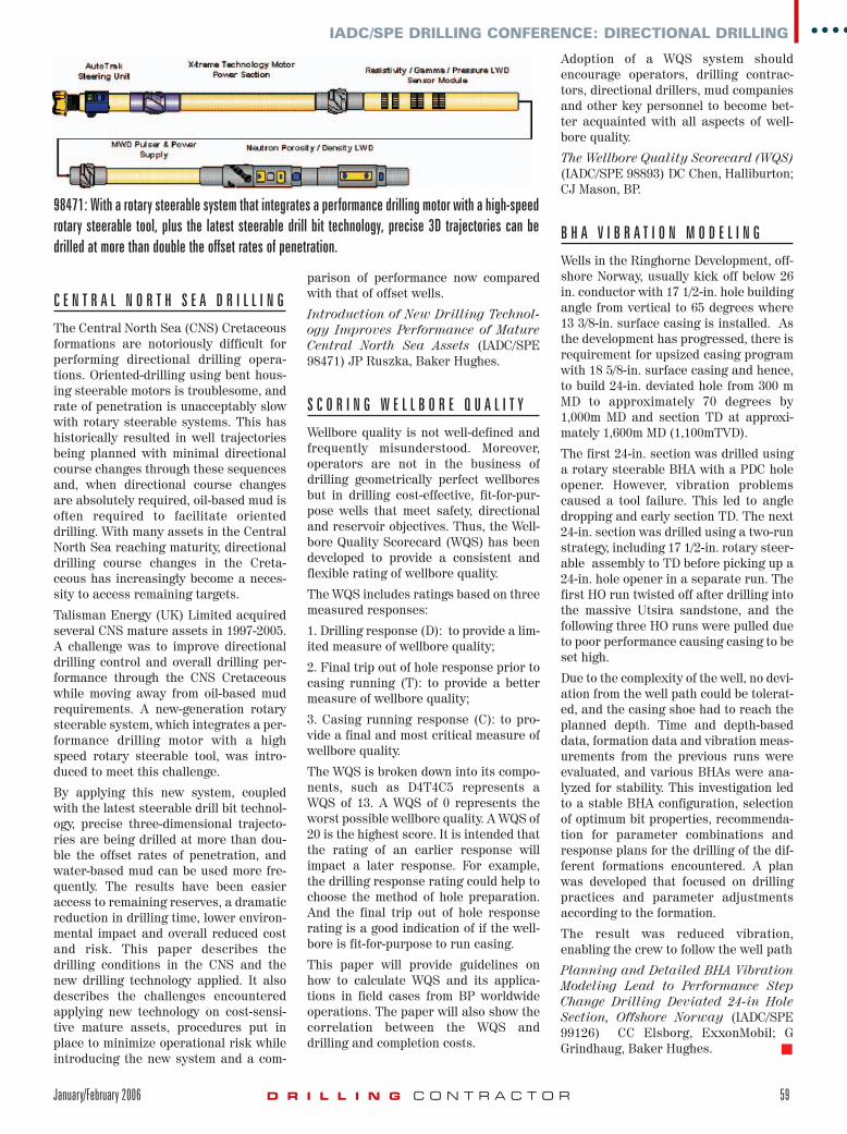
C E N T R A L N O R T H S E A D R I L L I N G
The Central North Sea (CNS) Cretaceousformations are notoriously difficult forperforming directional drilling opera-tions. Oriented-drilling using bent hous-ing steerable motors is troublesome, andrate of penetration is unacceptably slowwith rotary steerable systems. This hashistorically resulted in well trajectoriesbeing planned with minimal directionalcourse changes through these sequencesand, when directional course changesare absolutely required, oil-based mud isoften required to facilitate orienteddrilling. With many assets in the CentralNorth Sea reaching maturity, directionaldrilling course changes in the Creta-ceous has increasingly become a neces-sity to access remaining targets.
Talisman Energy (UK) Limited acquiredseveral CNS mature assets in 1997-2005.A challenge was to improve directionaldrilling control and overall drilling per-formance through the CNS Cretaceouswhile moving away from oil-based mudrequirements. A new-generation rotarysteerable system, which integrates a per-formance drilling motor with a highspeed rotary steerable tool, was intro-duced to meet this challenge.
By applying this new system, coupledwith the latest steerable drill bit technol-ogy, precise three-dimensional trajecto-ries are being drilled at more than dou-ble the offset rates of penetration, andwater-based mud can be used more fre-quently. The results have been easieraccess to remaining reserves, a dramaticreduction in drilling time, lower environ-mental impact and overall reduced costand risk. This paper describes thedrilling conditions in the CNS and thenew drilling technology applied. It alsodescribes the challenges encounteredapplying new technology on cost-sensi-tive mature assets, procedures put inplace to minimize operational risk whileintroducing the new system and a com-
parison of performance now comparedwith that of offset wells.
Introduction of New Drilling Technol-ogy Improves Performance of MatureCentral North Sea Assets (IADC/SPE98471) JP Ruszka, Baker Hughes.
S C O R I N G W E L L B O R E Q U A L I T Y
Wellbore quality is not well-defined andfrequently misunderstood. Moreover,operators are not in the business ofdrilling geometrically perfect wellboresbut in drilling cost-effective, fit-for-pur-pose wells that meet safety, directionaland reservoir objectives. Thus, the Well-bore Quality Scorecard (WQS) has beendeveloped to provide a consistent andflexible rating of wellbore quality.
The WQS includes ratings based on threemeasured responses:
1. Drilling response (D): to provide a lim-ited measure of wellbore quality;
2. Final trip out of hole response prior tocasing running (T): to provide a bettermeasure of wellbore quality;
3. Casing running response (C): to pro-vide a final and most critical measure ofwellbore quality.
The WQS is broken down into its compo-nents, such as D4T4C5 represents aWQS of 13. A WQS of 0 represents theworst possible wellbore quality. A WQS of20 is the highest score. It is intended thatthe rating of an earlier response willimpact a later response. For example,the drilling response rating could help tochoose the method of hole preparation.And the final trip out of hole responserating is a good indication of if the well-bore is fit-for-purpose to run casing.
This paper will provide guidelines onhow to calculate WQS and its applica-tions in field cases from BP worldwideoperations. The paper will also show thecorrelation between the WQS anddrilling and completion costs.
Adoption of a WQS system shouldencourage operators, drilling contrac-tors, directional drillers, mud companiesand other key personnel to become bet-ter acquainted with all aspects of well-bore quality.
The Wellbore Quality Scorecard (WQS)(IADC/SPE 98893) DC Chen, Halliburton;CJ Mason, BP.
B H A V I B R A T I O N M O D E L I N G
Wells in the Ringhorne Development, off-shore Norway, usually kick off below 26in. conductor with 17 1/2-in. hole buildingangle from vertical to 65 degrees where13 3/8-in. surface casing is installed. Asthe development has progressed, there isrequirement for upsized casing programwith 18 5/8-in. surface casing and hence,to build 24-in. deviated hole from 300 mMD to approximately 70 degrees by1,000m MD and section TD at approxi-mately 1,600m MD (1,100mTVD).
The first 24-in. section was drilled usinga rotary steerable BHA with a PDC holeopener. However, vibration problemscaused a tool failure. This led to angledropping and early section TD. The next24-in. section was drilled using a two-runstrategy, including 17 1/2-in. rotary steer-able assembly to TD before picking up a24-in. hole opener in a separate run. Thefirst HO run twisted off after drilling intothe massive Utsira sandstone, and thefollowing three HO runs were pulled dueto poor performance causing casing to beset high.
Due to the complexity of the well, no devi-ation from the well path could be tolerat-ed, and the casing shoe had to reach theplanned depth. Time and depth-baseddata, formation data and vibration meas-urements from the previous runs wereevaluated, and various BHAs were ana-lyzed for stability. This investigation ledto a stable BHA configuration, selectionof optimum bit properties, recommenda-tion for parameter combinations andresponse plans for the drilling of the dif-ferent formations encountered. A planwas developed that focused on drillingpractices and parameter adjustmentsaccording to the formation.
The result was reduced vibration,enabling the crew to follow the well path
Planning and Detailed BHA VibrationModeling Lead to Performance StepChange Drilling Deviated 24-in HoleSection, Offshore Norway (IADC/SPE99126) CC Elsborg, ExxonMobil; GGrindhaug, Baker Hughes. �
IADC/SPE DRILLING CONFERENCE: DIRECTIONAL DRILLING
January/February 2006 D R I L L I N G C O N T R A C T O R 59
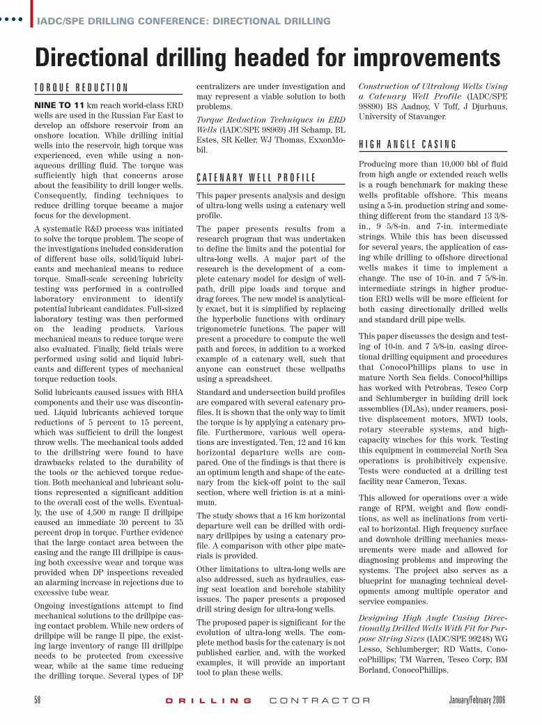
98471: With a rotary steerable system that integrates a performance drilling motor with a high-speedrotary steerable tool, plus the latest steerable drill bit technology, precise 3D trajectories can bedrilled at more than double the offset rates of penetration.
jan06-ab15.qxp 1/11/2006 2:21 PM Page 59