Embed Size (px)
Citation preview
INTERNATIONAL ASSOCIATION OF CLASSIFICATION SOCIETIES
Requirementsconcerning
FIRE PROTECTION
IACS Req. 2010
Contents, Page 1
CONTENTS
F1 Cathodic protection on oil tankers Rev. 1 June 2002
F2 Aluminium coatings on board oil tankers and chemical tankers Rev. 1 May 1998/Corr.1 March 1999
F3 Tank cleaning openings 1971
F4 Deleted 1987
F5 Pump room alarms Rev. 1 1973
F6 Standardization of flash points Rev. 1 1996
F7 Portable instruments for measuring oxygen and flammable vapour concentrations Rev. 2 May 1999
F8 Pressurisation of cargo tanks Rev. 1 1989
F9 Lighting and sighting ports in pump room/engine room bulkheads 1971
F10 Deleted 1986
F11 Deleted 1986
F12 Deleted
F13 Gland seals in pump room bulkheads Rev. 1 1977
F14 Deleted 1996
F15 Piping passing through dangerous zones Rev. 5 1996
F16 Bow and stern loading and unloading arrangements on oil tankers Rev. 1 June 2000
F17 Deleted 1996
F18 Deleted 1997
F19 Deleted 1988
F20 Inert gas systems Rev. 3 May 1998/Rev.5 Nov 2005
F21 Pump room ventilation 1974
F22 Direct loading pipes to oil tanker cargo tank 1974
F23 Deleted 1996
F24 Temperature of Steam and Heating Media within the Cargo Area Rev. 2 1998
IACS Req. 2005
▼
Contents, Page 2
F25 Deleted 1987
F26 Safety aspects of double bottoms and duct keels under cargo Rev.3 May 2004 oil tanks
F27 Cargo opening in the bottoms of topside tanks of ships carrying 1978alternatively oil and grain
F28 Deleted 1987
F29 Non-sparking fans Rev.6 June 2005
F30 Deleted - Feb 2002
F31 Deleted
F32 Fire detecting system for unattended machinery spaces 1976
F33 Prohibition of carriage in forepeak tanks of oil or other liquid substances 1981which are flammable
F34 Deleted July 2010
F35 Fire protection of machinery spaces Rev.8 June 2005
F36 Deleted 1989
F37 DELETED - May 1998
F38 DELETED - May 1998
F39 Deleted - July 2002
F40 Deleted 1997
F41 Sea intakes for fire pumps on ships with ICE class 1993
F42 Fire testing of flexible pipes 1995
F43 Installation Requirements for analysing units for continuous monitoring of flammable vapours Rev.2 Jun 2002
F44 Fore peak ballast system on oil tankers Rev.1 Aug 2008
See also M24 and Recommendations Nos. 1 and 3
IACS Req. 2010
� ������
F1–F3
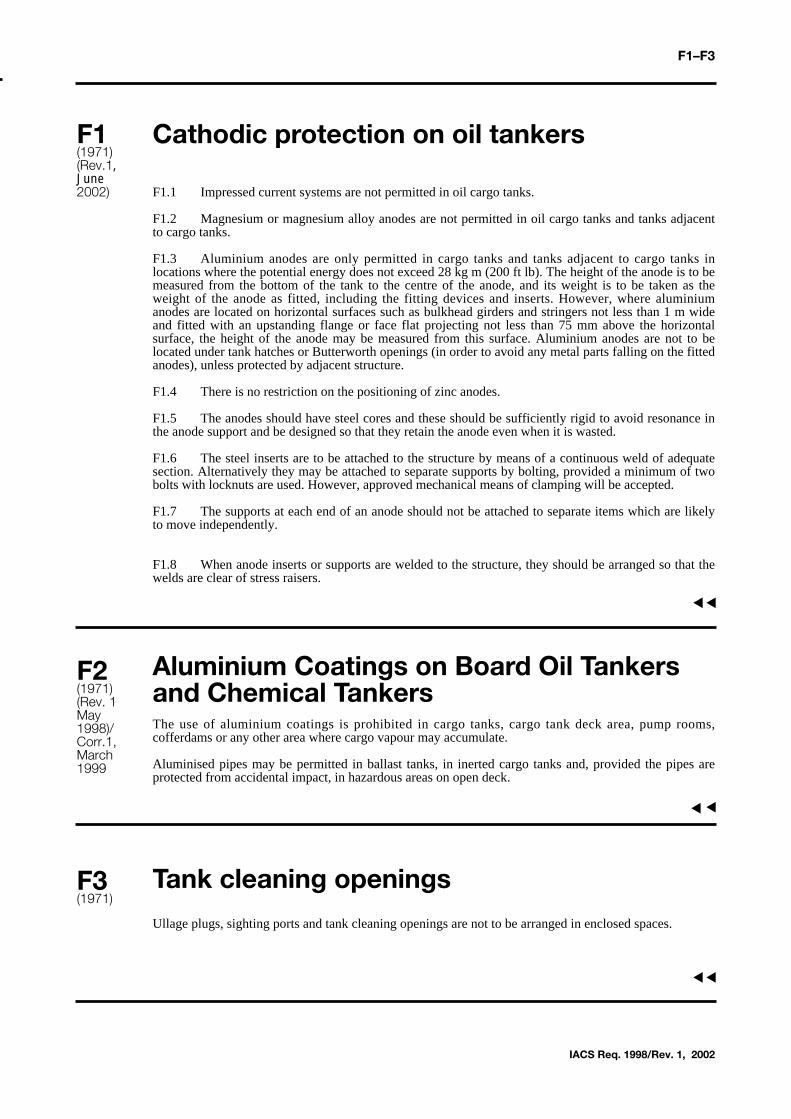
Cathodic protection on oil tankers
F1.1 Impressed current systems are not permitted in oil cargo tanks.
F1.2 Magnesium or magnesium alloy anodes are not permitted in oil cargo tanks and tanks adjacentto cargo tanks.
F1.3 Aluminium anodes are only permitted in cargo tanks and tanks adjacent to cargo tanks inlocations where the potential energy does not exceed 28 kg m (200 ft lb). The height of the anode is to bemeasured from the bottom of the tank to the centre of the anode, and its weight is to be taken as theweight of the anode as fitted, including the fitting devices and inserts. However, where aluminiumanodes are located on horizontal surfaces such as bulkhead girders and stringers not less than 1 m wideand fitted with an upstanding flange or face flat projecting not less than 75 mm above the horizontalsurface, the height of the anode may be measured from this surface. Aluminium anodes are not to belocated under tank hatches or Butterworth openings (in order to avoid any metal parts falling on the fittedanodes), unless protected by adjacent structure.
F1.4 There is no restriction on the positioning of zinc anodes.
F1.5 The anodes should have steel cores and these should be sufficiently rigid to avoid resonance inthe anode support and be designed so that they retain the anode even when it is wasted.
F1.6 The steel inserts are to be attached to the structure by means of a continuous weld of adequatesection. Alternatively they may be attached to separate supports by bolting, provided a minimum of twobolts with locknuts are used. However, approved mechanical means of clamping will be accepted.
F1.7 The supports at each end of an anode should not be attached to separate items which are likelyto move independently.
F1.8 When anode inserts or supports are welded to the structure, they should be arranged so that thewelds are clear of stress raisers.
Aluminium Coatings on Board Oil Tankersand Chemical TankersThe use of aluminium coatings is prohibited in cargo tanks, cargo tank deck area, pump rooms,cofferdams or any other area where cargo vapour may accumulate.
Aluminised pipes may be permitted in ballast tanks, in inerted cargo tanks and, provided the pipes areprotected from accidental impact, in hazardous areas on open deck.
Tank cleaning openings
Ullage plugs, sighting ports and tank cleaning openings are not to be arranged in enclosed spaces.
F1(1971)(Rev.1,June2002)
IACS Req. 1998/Rev. 1, 2002
F2(1971)(Rev. 1May1998)/Corr.1,March1999
▼▼▼▼
F3(1971)
▼▼
F4–F5
Deleted
Pump room alarms
Where audible alarms are fitted to warn of the release of fire extinguishing medium into pump rooms,they may be of the pneumatic type or electric type.
(a) Pneumatically operated alarms
In cases where the periodic testing of such alarms is required,CO2 operated alarms should not beused owing to the possibility of the generation of static electricity in the CO2 cloud. Air operatedalarms may be used provided the air supply is clean and dry.
(b) Electrically operated alarms
When electrically operated alarms are used, the arrangements are to be such that the electricactuating mechanism is located outside the pump room except where the alarms are certifiedintrinsically safe.
It was further agreed that the use of CO2 operated alarms should be discouraged.
F4
IACS Req. 1987
F5(1971)(Rev. 11973)
▼▼▼▼

F6
Standardization of flash points
In context of these Unified Requirements, oil tankers shall be considered as vessels capable of carryingoil having a flash point not exceeding 60°C (closed cup test).
IACS Req. 1971/Rev 1 1996
F6(1971)(Rev 11996)
▼▼
F7
Portable instruments for measuring oxygen and flammable vapour concentrations
Every oil tanker is to be provided with at least two portable gas detectors capable of measuringflammable vapour concentrations in air and at least two portable O2 analysers.
In addition, for tankers fitted with inert gas systems, at least two portable gas detectors are to be capableof measuring concentrations of flammable vapours in inerted atomosphere.
IACS Req. 1999
F7(1971)(Rev. 11989)(Rev.2May 1999)
▼▼
Pressurisation of cargo tanks
PV valves to oil tanks should not be set at pressures in excess of 0,21 bar unless the tank scantlings havebeen specially considered.
Lighting and sighting ports in pumproom/engine room bulkheads
F9.1 Where the pump room is illuminated through glazed ports, these are to be effectively protectedfrom mechanical damage and are to have strong covers secured from the side of the sage space.
F9.2 Glazed ports are to be so constructed that glass and sealing will not be impaired by the workingof the ship.
F9.3 The glass and the protection of the light fitting are not to impair the integrity of the bulkheadand are to be of equivalent strength.
F9.4 The fitting is to have the same resistance to fire and smoke as the unpierced bulkhead.
Deleted
Deleted
Deleted
IACS Req. 1989
F8(1971)(Rev. 11989)
F9(1971)
F10
F11
F12
▼▼▼▼
▼▼▼▼
▼▼F8-F12
F13
Gland seals in pump room bulkheads
Where drive shafts pass through pump room bulkhead or deck plating, gastight glands are to be fitted.The glands are to be efficiently lubricated from outside the pumproom. The seal parts of the glands are tobe of material that will not initiate sparks. The glands are to be constructed and fitted in accordance withthe relative rules for fittings attached to watertight bulkheads, and if a bellows piece is incorporated inthe design, it should be pressure tested before fitting.
F13(1972)(Rev. 11977)
IACS Req. 1989
▼▼

F14
Deleted- the requirements are now addressed by IMO Res. A.446 (XI)
F14
IACS Req. 1989/Rev 1996
▼▼

F15
Piping passing through dangerous zones
F15.1 Ballast piping passing through cargo tanks and cargo oil pipes passing through segregatedballast tanks, as permitted by MARPOL Annex 1 Reg. 13F, are to comply with the followingrequirements.
F15.1.1 The pipes are to be of heavy gauge steel of minimum wall thickness according to the tablehereunder with welded or heavy flanged joints the number of which is to be kept to a minimum.
Expansion bends only (not glands) are permitted in these lines within cargo tanks for serving the ballasttanks and within the ballast tanks for serving the cargo tanks.
Nominal diameter Minimum wall(mm) thickness
(mm)
50 6,3100 8,6125 9,5150 11,0
200 and above 12,5
F15.2 The thicknesses shown in the above table refer to carbon steel.
F15.3 Connection between cargo piping and ballast piping referred to above is not permitted exceptfor emergency discharge as specified in the Unified Interpretation to Reg. 1 (17) of MARPOL 73/78,Annex 1.
Nevertheless, provision may be made for emergency discharge of the segregated ballast by means of aconnection to a cargo pump through a portable spool piece. In this case non-return valves should be fittedon the segregated ballast connections to prevent the passage of oil to the ballast tanks. The portable spoolpiece should be mounted in a conspicuous position in the pump room and a permanent notice restrictingits use should be prominently displayed adjacent to it.
Shut-off valves shall be provided to shut off the cargo and ballast lines before the spool piece is removed.
F15.4 The ballast pump is to be located in the cargo pump room, or a similar space within the cargoarea not containing any source of ignition.
IACS Req. 1982/Rev 5. 1996
▼▼
F15(1982)(Rev. 41989)(Rev 5.1996)
F15-1
Bow and stern loading and unloadingarrangements on oil tankers
Where a cargo hose connection is arranged outside the cargo tank area, the pipe leading to suchconnections is to be provided with means of segregation such as a spectacle flange, removable spoolpiece or equivalent* located within the cargo area. The space within 3 m of the manifold is to beconsidered as a dangerous area with regard to electrical or incendive equipment.
* See MSC/Circ. 474.
16
IACS Req. 1972/Rev.1 2000
▼▼
F16(1972)(Rev.1June 2000)

F17
Deleted- this is of a general nature concerning operational matters and should not be categorosed as UR.
F17
IACS Req. 1986/Rev 1996
▼▼
F18-19
Deleted (1997)
Deleted
F18
IACS Req. 1997
▼
F19
▼▼▼
Inert Gas Systems
F20.1 General Requirements
F20.1.1 All types of inert gas systems are to comply with the following:
.1 Plans in diagrammatic form are to be submitted for appraisal and should include the following:
- details and arrangement of the inert gas generating plant including all control and monitoring devices;
- arrangement of the piping system for distribution of the inert gas.
.2 An automatic control capable of producing suitable inert gas under all service conditions is to be fitted.
.3 Materials used in inert gas systems are to be suitable for their intended purpose in accordance with the Rules of the Classification Society.
.4 All the equipment is to be installed on board and tested under working conditions to the satisfaction of the Surveyor.
.5 Subsequent surveys are to be carried out at the intervals required by the Classification SocietyRules.
F20.2 Inert Gas Systems on Tankers Carrying Crude Oil and Petroleum Products
F20.2.1 The following requirements apply where an inert gas system based on boiler flue gas and oilfired inert gas generators is fitted on board tankers intended for the carriage of crude oil and petroleumproducts in bulk having a flashpoint not exceeding 60°C (closed cup test) as determined by an approvedflashpoint apparatus, and a Reid vapour pressure which is below atmospheric pressure, and other liquidproducts having a similar fire hazard.
F20.2.2 The inert gas system is to comply with the requirements of Ch. 15 of the FSS Code, insofar asthey are applicable to new ships only.
Any use of the word "Administration" in the Regulation is to be considered as meaning the relevantClassification Society.
F20.2.3 In addition to the requirements detailed in Ch. 15 of the FSS Code, the following is to becomplied with:
.1 When two blowers are provided, the total required capacity of the inert gas system is preferably tobe divided equally between the two blowers, and in no case is one blower to have a capacity lessthan 1/3 of the total capacity required.
.2 In particular those parts of scrubbers, blowers, non-return devices, scrubber effluent and otherdrain pipes which may be subjected to corrosive action of the gases and/or liquids are to be eitherconstructed of corrosion resistant material or lined with rubber, glass fibre epoxy resin or otherequivalent coating material.
.3 The compartment in which any oil fired inert gas generator is situated is to be treated asmachinery space of Category A with respect to fire protection.
▼
F20
IACS Req. 1997, Rev.5 2005
F20(1984)(Rev.11983(Rev. 21987)(Rev. 3May,1998)(Corr.Sept.2001)(Rev.4May 2004)(Rev.5 Nov. 2005)
F20-1
.4 Arrangements are to be made to vent the inert gas from oil fired inert gas generators to theatmosphere when the inert gas produced is off specification, e.g., during start-up or in the event ofequipment failure.
.5 Automatic shut-down of the oil fuel supply to inert gas generators is to be arranged onpredetermined limits being reached with respect to low water pressure or low water flow rate tothe cooling and scrubbing arrangement and with respect to high gas temperature.
.6 Automatic shut-down of the gas regulating valve is to be arranged with respect to failure of thepower supply to the oil fired inert gas generators.
F20.3 Inert Gas Systems on Chemical Tankers
F20.3.1 The following requirements apply where an inert gas system based on oil fired inert gasgenerators is fitted on board chemical tankers.
F20.3.2 The inert gas system is to comply with the requirements of Resolution A.567(14).
Any use of the word "Administration" in the Resolution is to be considered as meaning the relevantClassification Society.
F20.3.3 As an alternative to the water seal in the inert gas line on deck, an arrangement consisting of twoshut-off valves in series with a venting valve in between may be accepted (double block and bleed) . Thefollowing conditions apply:
- The operation of the valve is to be automatically executed. Signal(s) for opening/closing is (are)to be taken from the process directly, e.g. inert gas flow or differential pressure.
- Alarm for faulty operation of the valves is to be provided, e.g. the operation status of "Blowerstop" and "supply valve(s) open" is an alarm condition.
F20.3.4 In addition to the requirements detailed in Resolution A.567(14), the requirements for inert gassystems, contained in paragraphs F20.2.3.1 to F20.2.3.3, are to be complied with.
F20.4 Nitrogen Generator Systems
F20.4.1 The following requirements are specific only to the gas generator system and apply where inertgas is produced by separating air into its component gases by passing compressed air through a bundle ofhollow fibres, semi-permeable membranes or adsorber materials.
F20.4.2 Where such systems are provided in place of the boiler flue gas or oil fired inert gas generatorsreferred to in sections F20.2 and F20.3, the following requirements of the FSS Code, Ch. 15 orequivalent requirements of Resolution A.567(14) remain applicable for the piping arrangements, alarmsand instrumentation downstream of the gas generator: 2.3.1.3.1, 2.3.1.3.2, 2.3.1.5, 2.3.2, 2.4.2, 2.4.3.1.6,2.4.3.1.8, 2.4.3.1.9, 2.4.3.3, 2.4.3.4, 2.4.4, as well as SOLAS Reg.II-2/4.5.3.4.2, 4.5.6.3, 11.6.3.4
F20.4.3 A nitrogen generator consists of a feed air treatment system and any number of membrane oradsorber modules in parallel necessary to meet the required capacity which is to be at least 125% of themaximum discharge capacity of the ship expressed as a volume.
F20.4.4 The air compressor and the nitrogen generator may be installed in the engine room or in aseparate compartment. A separate compartment is to be treated as one of "Other machinery spaces" withrespect to fire protection.
F20.4.5 Where a separate compartment is provided, it is to be positioned outside the cargo area and is tobe fitted with an independent mechanical extraction ventilation system providing 6 air changes per hour.A low oxygen alarm is to be fitted as well.
The compartment is to have no direct access to accommodation spaces, service spaces and controlstations.
F20
F20cont'd
▼
F20-2IACS Req. 1997, Rev.5 2005
F20
F20.4.6 The nitrogen generator is to be capable of delivering high purity nitrogen with O2 content notexceeding 5% by volume. The system is to be fitted with automatic means to discharge "off-spec" gas tothe atmosphere during start-up and abnormal operation.
F20.4.7 The system is to be provided with two air compressors. The total required capacity of the systemis preferably to be divided equally between the two compressors, and in no case is one compressor tohave a capacity less than 1/3 of the total capacity required.
Only one air compressor may be accepted provided that sufficient spares for the air compressor and itsprime mover are carried on board to enable their failure to be rectified by the ship's crew.
F20.4.8 A feed air treatment system is to be fitted to remove free water, particles and traces of oil fromthe compressed air, and to preserve the specification temperature.
F20.4.9 Where fitted, a nitrogen receiver/buffer tank may be installed in a dedicated compartment or inthe separate compartment containing the air compressor and the generator or may be located in the cargoarea. Where the nitrogen receiver/buffer tank is installed in an enclosed space, the access is to bearranged only from the open deck and the access door is to open outwards. Permanent ventilation andalarm are to be fitted as required by paragraph F20.4.5.
F20.4.10The oxygen-enriched air from the nitrogen generator and the nitrogen-product enriched gasfrom the protective devices of the nitrogen receiver are to be discharged to a safe location on the opendeck.
F20.4.11In order to permit maintenance, means of isolation are to be fitted between the generator and thereceiver.
F20.4.12At least two non-return devices are to be fitted in the inert gas supply main, one of which is tobe of the double block and bleed arrangement (refer to paragraph F20.3.3). The second non-return deviceis to be equipped with positive means of closure.
F20.4.13Instrumentation is to be provided for continuously indicating the temperature and pressure ofair:
.1 at the discharge side of the compressor,
.2 at the entrance side of the nitrogen generator.
F20.4.14Instrumentation is to be fitted for continuously indicating and permanently recording theoxygen content of the inert gas downstream of the nitrogen generator when inert gas is being supplied.
F20.4.15The instrumentation referred to in paragraph F20.4.14 is to be placed in the cargo control roomwhere provided. But where no cargo control room is provided, they shall be placed in a position easilyaccessible to the officer in charge of cargo operations.
F20.4.16Audible and visual alarms are to be provided to indicate :
.1 low feed-air pressure from compressor as referred to in paragraph F20.4.13.1,
.2 high air temperature as referred to in paragraph F20.4.13.1,
.3 high condensate level at automatic drain of water separator as referred to in paragraph F20.4.8,
.4 failure of electrical heater, if fitted,
.5 oxygen content in excess of that required in paragraph F20.4.6,
.6 failure of power supply to the instrumentation as referred to in paragraph F20.4.14.
F20.4.17Automatic shut-down of the system is to be arranged upon alarm conditions as required byparagraphs F20.4.16.1 to .5.
F20cont’d
▼
F20-3 IACS Req. 1997, Rev.5 2005
F20
F20.4.18The alarms required by paragraphs F20.4.16.1 to .6 are to be fitted in the machinery space andcargo control room, where provided, but in each case in such a position that they are immediatelyreceived by responsible members of the crew.
F20.5 Nitrogen /inert gas systems fitted for purposes other than inerting required by SOLAS Reg II-2/4.5.5.1.1
F20.5.1 This section applies to systems fitted on oil tankers of less than 20.000 DWT, gas tankers orchemical tankers.
F20.5.2 The requirements of section F20.4 apply except paragraphs F20.4.1, F20.4.2, F20.4.3 andF20.4.7.
F20.5.3 Where the connections to the cargo tanks, to the hold spaces or to cargo piping are notpermanent, the non-return devices required by paragraph F20.4.12 may be substituted by two non-returnvalves.
F20cont’d
▼▼
F20-4IACS Req. 1997, Rev.5 2005
Pump room ventilation
With the following arrangement of exhaust trunking there should be 20 air changes per hour on the totalvolume of the pump room:
(i) In the pump room bilges just above the transverse floor plates on bottom longitudinals, so thatair can flow over the top from adjacent spaces.
(ii) An emergency intake located about 2 m above the pump room lower grating. This emergencyintake would be used when the lower intakes are sealed off due to flooding in the bilges. Theemergency intake should have a damper fitted which is capable of being opened or closedfrom the exposed main deck and lower grating level.
(iii) The foregoing exhaust system is in association with open grating floor plates to allow the freeflow of air.
(iv) Arrangements involving a specific ratio of areas of upper emergency and lower mainventilator openings, which can be shown to result in at least the required 20 air changes perhour through the lower inlets, can be adopted without the use of dampers. When the loweraccess inlets are closed then at least 15 air changes per hour should be obtained through theupper inlets.
Direct loading pipes to oil tanker cargotanks
In order to avoid the generation of static electricity when cargo is loaded direct into tanks, the loadingpipes are to be led as low as practicable in the tank.
F21-F22
F22(1974)
IACS Req. 1987
▼▼
F21(1974)
▼▼

F23
Deleted- the requirements are overtaken by the development of MARPOL Convention.
IACS Req. 1986/Rev 1996
F23
▼▼
F24-F25
Temperature of Steam and Heating Mediawithin the Cargo AreaOn oil tankers, the steam and heating media temperature within the cargo area is not to exceed 220°C.
On gas carriers and chemical tankers, the maximum temperature is to be adjusted to take into account thetemperature class of the cargoes.
Deleted
F24(1971)(Rev. 11975(Rev. 2May 1998)
IACS Req. 1971, Rev. 2 1998
▼
F25
▼▼▼
Safety aspects of double bottoms and ductkeels under cargo oil tanks
Pipe ducts in the double bottom shall comply with the following requirements:
(i) They should not communicate with the engine room.(ii) Provision shall be made for at least two exits to the open deck arranged at a
maximum distance from each other. One of these exits fitted with a watertightclosure may lead to the cargo pumproom.
(iii) In the duct, provision shall be made for adequate mechanical ventilation.
Note: For ships to which the convention applies, refer to SOLAS 1974 (as amended),Reg II-2/4.5.2.4
_______________________________
IACS Req. 1977/Rev .3 2004
F26
F26(1977)(Rev 11996)(Rev.2June 2000)(Rev.3May 2004)
▼▼
F26-1
Revision Note: Rev.3 only updates references
F27-F28
Cargo openings in the bottoms of topsidetanks of ships carrying alternatively oil andgrain
Ships carrying alternatively oil having a flash point not exceeding 60°C (closed cup test) or other cargoes.
When ships are designed to transport alternatively oil or dry cargoes, openings which may be used forcargo operations are not permitted in bulkheads and decks separating oil cargo spaces from other spacesnot designed and equipped for the carriage of oil cargoes unless alternative approved means are providedto ensure equivalent integrity.
Deleted
IACS Req. 1986
▼
F28
F27(1978)
▼▼
F29
Non-sparking fans
F29.1 Introduction
A fan is considered as non-sparking if in either normal or abnormal conditions it is unlikely to producesparks.
F29.2 Design criteria
F29.2.1 The air gap between the impeller and the casing shall be not less than 0,1 of the shaft diameterin way of the impeller bearing but not less than 2 mm. It need not be more than 13 mm.
F29.2.2 Protection screens of not more than 13 mm square mesh are to be fitted in the inlet and outletventilation openings on the open deck to prevent the entrance of objects into the fan housing.
F29.3 Materials
F29.3.1 The impeller and the housing in way of the impeller are to be made of alloys which arerecognised as being spark proof by appropriate test.
F29.3.2 Electrostatic charges both in the rotating body and the casing are to be prevented by the use ofantistatic materials. Furthermore, the installation on board of the ventilation units is to be such as toensure the safe bonding to the hull of the units themselves.
F29.3.3 Tests may not be required for fans having the following combinations:
(i) impellers and/or housings of nonmetallic material, due regard being paid to the elimination of staticelectricity,
(ii) impellers and housings of non-ferrous materials,(iii) Impellers of aluminium alloys or magnesium alloys and a ferrous (including austenitic stainless
steel) housing on which a ring of suitable thickness on non-ferrous materials is fitted in way of theimpeller,
(iv) any combination of ferrous (including austenitic stainless steel)impellers and housings with not lessthan 13 mm tip design clearance.
F29.3.4 The following impellers and housings are considered as sparking and are not permitted:
(i) impellers of an aluminium alloy or magnesium alloy and a ferrous housing, regardless of tipclearance,
(ii) housing made of an aluminium alloy or a magnesium alloy and a ferrous impeller, regardless of tipclearance,
(iii) any combination of ferrous impeller and housing with less than 13 mm design tip clearance.
F29.3.5 Type tests on the finished product are to be carried out in accordance with the requirements ofthe Classification Society or an equivalent national or international standard.
F29(1973)(Rev. 11978)(Rev. 21979)Rev. 31980)(Rev. 41983)(Rev. 51994)(Rev.6June2005)
IACS Req. Rev.6 2005
▼▼
F29-1
Emergency fire pumps in cargo ships
Deleted in February 2002.
F30.1–F30.2.6
F30(1974)(Rev. 11976)(Rev. 21978)Rev. 31980)Rev. 41984)Rev. 51995)(Rev 61997)(Rev. 7Feb 2002)
IACS Req. 1984, Rev. 1997
▼
F30-1
F30.2.7–F30.4.2
Fire prevention for unattended machineryspacesThe whole UR F31 was deleted as the requirements are now covered by F35.
F30cont'd
IACS Req. 1984, Rev. 1995/Corr. 1997
▼▼
F31(1976)
F30-2
▼▼
F32
Fire detecting system for unattendedmachinery spaces
F32.1 An automatic fire detection system is to be fitted in the machinery spaces.
F32.2 The system is to be designed with self-monitoring properties. Power or system failures are toinitiate an audible alarm distinguishable from the fire alarm.
F32.3 The fire detection indicating panel is to be located on the navigating bridge, fire control station,or other accessible place where a fire in the machinery space will not render it inoperative.
F32.4 The fire detection indicating panel is to indicate the place of the detected fire in accordance withthe arranged fire zones by means of a visual signal. Audible signals clearly distinguishable in characterfrom any other audible signals shall be audible throughout the navigating bridge and the accommodationarea of the personnel responsible for the operation of the machinery space.
F32.5 Fire detectors are to be of types, and so located, that they will rapidly detect the onset of fire inconditions normally present in the machinery space. Consideration is to be given to avoiding falsealarms. The type and location of detectors are to be approved by the Classification Society and acombination of detector types is recommended in order to enable the system to react to more than onetype of fire symptom.
F32.6 Fire detector zones are to be arranged in a manner that will enable the operating staff to locatethe seat of the fire. The arrangement and the number of loops and the location of detector heads is to beapproved in each case. Air currents created by the machinery are not to render the detection systemineffective.
F32.7 When fire detectors are provided with the means to adjust their sensitivity, necessaryarrangements are to be ensured to fix and identify the set point.
F32.8 When it is intended that a particular loop or detector is to be temporarily switched off, this state isto be clearly indicated. Reactivation of the loop or detector is to be performed automatically after apresent time.
F32.9 The fire detection indicating panel is to be provided with facilities for functional testing.
F32.10 The fire detecting system shall be fed automatically from the emergency source of power by aseparate feeder if the main source of power fails.
F32.11 Facilities are to be provided in the fire detecting system to release manually the fire alarm fromthe following places:
Passageways having entrances to engine and boiler rooms,navigating bridge,control station in engine room.
F32.12 The testing of the fire detecting system on board is to be carried out to the satisfaction of theindividual Classification Society.
NOTERequirements on indication of the operation of each individual detecting head are left to the discretion ofeach Classification Society.
IACS Req. 1976
F32(1976)
F32-1
▼▼
F33
Prohibition of carriage in fore peak tanks ofoil or other liquid substances which areflammable
In ships of 400 tons gross tonnage and above, compartments forward o f the collision bulkhead shall notbe arranged for the carriage of oil or other liquid substances which are flammable.
IACS Req. 1981
▼▼
F33(1981)
F33-1
F34
Page 1 of 1 IACS Req. 1982 / Rev.1 1989
A2(cont)
Low-pressure carbon dioxide smotheringsystemsDeleted with effect from 1 July 2010 following entry into force of IMO Res. MSC.206(81).
F34(1982)(Rev.11989)
End ofDocument
Fire Protection of Machinery Spaces
In the implementation of the SOLAS Chapter II-2, the following requirements areto be met:
1. Reg.II-2/4.2.2.4
Air pipes from oil fuel tanks should be led to a safe position on the open deck.
Air pipes from lubricating oil storage tanks may terminate in the machinery space,provided that the open ends are so situated that issuing oil cannot come into contactwith electrical equipment or heated surfaces.
Any overflow pipe should have a sectional area of at least 1,25 times that of the fillingpipe and should be led to an overflow tank of adequate capacity or to a storage tankhaving space reserved for overflow purposes.
An alarm device should be provided to give warning when the oil reaches apredetermined level in the tank, or alternatively, a sight glass should be provided in theoverflow pipe to indicate when any tank is overflowing. Such sight glasses should beplaced on vertical pipes only and in readily visible positions.
2. Reg.II-2/4.2.2.3.5.1
Short sounding pipes may be used for tanks other than double bottom tanks withoutthe additional closed level gauge provided an overflow system is fitted.
3. Reg.II-2/4.2.2.3
Level switches may be used below the tank top provided they are contained in a steelenclosure or other enclosures not capable of being destroyed by fire.
4. Reg.II-2/5.2.2.3
Controls required by this regulation should also be provided from the compartmentitself.
5. Reg.II-2/4.2.2.5.1
Hose clamps and similar types of attachments for flexible pipes should not bepermitted.
6. Reg.II-2/4.2.2 and 4.2.5.2
Oil fuel in storage tanks should not to be heated to temperatures within 10°C below theflash point of the fuel oil, except that where oil fuel in service tanks, settling tanks andany other tanks in supply system is heated the following arrangements should beprovided:
• the length of the vent pipes from such tanks and/or a cooling device is sufficient
F35
F35(1986)(Rev. 11989)(Rev. 21992)(Rev. 31995)(Rev. 41996)(Rev. 5 1997)(Rev. 6June 1999)(Rev.7July 2003)(Rev.8June 2005)
IACS Req. 1986, Rev.8, 2005 F35-1
▼
F35
for cooling the vapours to below 60°C, or the outlet of the vent pipes is located 3m away from a source of ignition;
• the vent pipes are fitted with flame screens;
• there are no openings from the vapour space of the fuel tanks into machinery spaces (bolted manholes are acceptable) ;
• enclosed spaces are not located directly over such fuel tanks, except for vented cofferdams ;
• electrical equipment is not fitted in the vapour space of the tanks, unless it is certified to be intrinsically safe.
F35cont'd
IACS Req. 1986, Rev.8 2005
F35-2
▼▼

IACS Req. 1996
F36
DeletedF36
F36-1
▼▼
IACS Req. 1989, Rev. 1998
UR F37 has been recategorised to beRecom 53.1 and deleted (May, 1998).
F38 has been re-categorised to be Recom. 53.2 and deleted (May 1998).
F37 & F38
F37
F38
▼▼▼▼
Measures to prevent explosions in cargo pump rooms on oil tankers
F 39 was deleted on 1 July 2002.
F39
IACS Req. 1993, Rev. 4 2001
F39(1993)(Rev. 11994)(Rev 21997)(Rev. 2/Corr. 11998)(Rev.3July 1999)(Rev.4May 2001)
Deleted 1997
Sea intakes for fire pump on ships with ICE Class1. On ships with ICE Class at least one of the fire pumps is to be connected to a sea chest which isprovided with de-icing arrangements.
F40
IACS Req. 1997
F41(1993)
▼▼▼▼
Fire testing of flexible pipes
1. Flexible pipes with end attachments which are required to be of fire-resisting materials, shall besubject to a fire for 30 minutes at a temperature of 800oC, while water at the maximum service pressureis circulated inside the pipe. The temperature of the water at the outlet shall not be less than 80oC. Noleak should be recorded during or after the test.
2. An alternative is to fire test the flexible pipe with flowing water at a pressure of at least 5 bar andsubsequent pressure test to twice the design pressure.
IACS Req. 1995
F42(1995)
F 42
▼▼
F42-1
F43
Installation requirements for analysing units for continuous monitoring of flammable vapours
This UR applies to gas analysing units of the sampling type located outside gas dangerous zones andfitted on board gas carriers or on board oil/chemical tankers.
Gas analysing units with non-explosion proof measuring equipment may be located in areas outsidecargo areas, e.g. in cargo control room, navigation bridge or engine room when mounted on the forwardbulkhead provided the following requirements are observed:
1. Sampling lines shall not run through gas safe spaces, except where permitted under 5.
2. The gas sampling pipes shall be equipped with flame arresters. Sample gas is to be led to theatmosphere with outlets arranged in a safe location.
3. Bulkhead penetrations of sample pipes between safe and dangerous areas shall be of approvedtype and have same fire integrity as the division penetrated. A manual isolating valve shall be fitted ineach of the sampling lines at the bulkhead on the gas safe side.
4. The gas detection equipment including sample piping, sample pumps, solenoids, analysing unitsetc. shall be located in a reasonably gas tight enclosure (e.g. a fully enclosed steel cabinet with a gasketeddoor) which is to be monitored by its own sampling point. At gas concentrations above 30% LFL insidethe enclosure the entire gas analysing unit is to be automatically shut down.
5. Where the enclosure cannot be arranged directly on the bulkhead, sample pipes shall be of steel orother equivalent material and without detachable connections, except for the connection points forisolating valves at the bulkhead and analysing units, and are to be routed on their shortest ways.
F43(1997)(Rev.1July1999)(Rev. 2June 2002)
IACS Req. 1997/Rev. 2 2002
▼ ▼
F43-1
F44
Page 1 of 1 IACS Req. 2000/Rev.1 2008
A2(cont)
Fore peak ballast system on oil tankers
The fore peak tank can be ballasted with the system serving other ballast tanks within thecargo area, provided:
• The fore peak tank is considered as hazardous;
• The vent pipe openings are located on open deck 3 m away from sources of ignition;
• Means are provided, on the open deck, to allow measurement of flammable gasconcentrations within the fore peak tank by a suitable portable instrument;
• The sounding arrangement to the fore peak tank is direct from open deck;
• The access to the fore peak tank is direct from open deck. Alternatively, indirect accessfrom the open deck to the fore peak tank through an enclosed space may be acceptedprovided that:
1. In case the enclosed space is separated from the cargo tanks by cofferdams, theaccess is through a gas tight bolted manhole located in the enclosed space and a warningsign is to be provided at the manhole stating that the fore peak tank may only be openedafter:
• it has been proven to be gas free; or• any electrical equipment which is not certified safe in the enclosed space is isolated.
2. In case the enclosed space has a common boundary with the cargo tanks and istherefore hazardous, the enclosed space can be well ventilated.
F44(June2000)(Rev.1Aug 2008)
End ofDocument