Embed Size (px)
Citation preview
8/2/2019 Iacs Bridge Design,Equipmenr Arrangement and Procedure.
http://slidepdf.com/reader/full/iacs-bridge-designequipmenr-arrangement-and-procedure 1/80
1
Recommendation for the Application of SOLASRegulation V/15
Bridge Design, Equipment Arrangement and
Procedures (BDEAP)
Foreword
This Recommendation sets forth a set of guidelines for determining compliance with the
principles and aims of SOLAS regulation V/15 relating to bridge design, design and
arrangement of navigational systems and equipment and bridge procedures when applying the
requirements of SOLAS regulations V/19, 22, 24, 25, 27 and 28 at the time of delivery of the
newbuilding.
The development of this Recommendation has been based on the international regulatory
regime and IMO instruments and standards already accepted and referred to by IMO. The platform for the Recommendation is:
• the aims specified in SOLAS regulation V/15 for application of SOLAS regulations
V/19, 22, 24, 25, 27 and 28
• the content of SOLAS regulations V/19, 22, 24, 25, 27, 28
• applicable parts of MSC/Circ.982, “Guidelines on ergonomic criteria for bridge
equipment and layout”
• applicable parts of IMO resolutions and performance standards referred to in SOLAS
• applicable parts of ISO and IEC standards referred to for information in MSC/Circ.982
•
STCW Code• ISM Code
This Recommendation is developed to serve as a self-contained document for the understanding
and application of the requirements, supported by:
• Annex A giving guidance and examples on how the requirements set forth may be met
by acceptable technical solutions. The guidance is not regarded mandatory in relation to
the requirements and does not in any way exclude alternative solutions that may fulfil
the purpose of the requirements.
o Appendix 1 to Annex A, “Tasks and related means – Examples of location of
main equipment”
• Annex B “Facts and principles – Related to SOLAS V/15 and the IACS
Recommendation” that should assist in achieving a common understanding of the
content of SOLAS regulation 15 and the approach and framework of the
Recommendation.
o Appendix 1 to Annex B clarifying the content of each aim of SOLAS regulation
V/15.
Chapter C 2 “Bridge alarm management” is established by compilation of relevant IMO and
classification requirements and guidelines. The chapter is recommended for compliance until
superseded by an IMO performance standard.
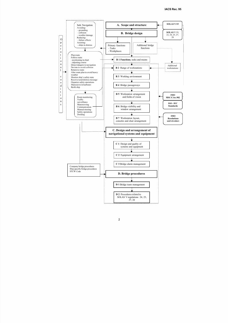
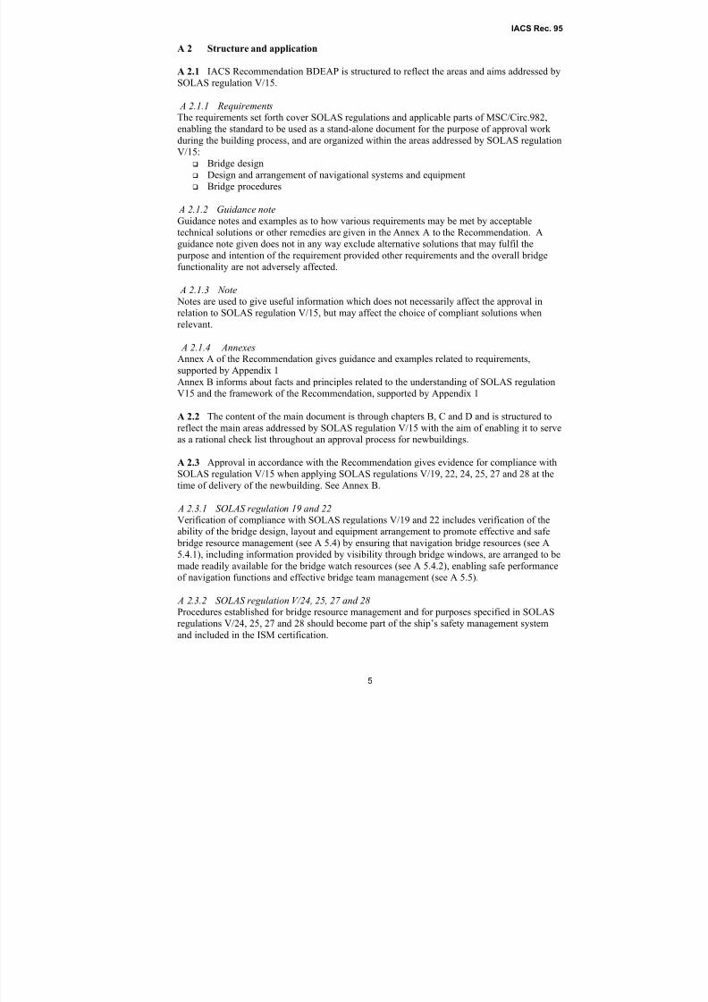
The diagram following this foreword gives an overview of approach and content.
No.95(Oct 2007)(Corr.1Mar 2009)
8/2/2019 Iacs Bridge Design,Equipmenr Arrangement and Procedure.
http://slidepdf.com/reader/full/iacs-bridge-designequipmenr-arrangement-and-procedure 2/80
IACS Rec. 95
2
O per ational
c
ondition
s
Safe NavigationAvoiding:- grounding
- collision
- weather damageReducing:
- failure effectsAssisting:
- ships in distress
Route monitoring
Trafficsurveillance
Manoeuvring
Communication
Manual steeringSafety operations
Docking
Plan routeFollow route
- positioning in chart- adjusting course
Detect dangers to navigation
Deviate to avoid collision
Return to routeAlter route plan to avoid heavy
weather
Monitor ship’s safety state
Receive/send distress messageOrganize safety operations
Manoeuvre in harboursBerth ship
Primary functions
- Tasks
- Workplaces
B. Bridge design
Additional bridge
functions
A. Scope and structure
C 2 Equipment arrangement
C 1 Design and quality of
systems and equipment
C. Design and arrangement of
navigational systems and equipment
C 3 Bridge alarm management
D. Bridge procedures
D 1 Bridge team management
D 2 Procedures related toSOLAS V regulations 24, 25,
27, 28
B 4 Bridge passageways
B 2 Range of workstations
B 6 Bridge visibility and
window arrangement
B 3 Working environment
B 1 Functions, tasks and means
B 5 Workstation arrangement
and fields of vision
B 7 Workstation layout,
consoles and chair arrangement
SOLAS V/15
SOLAS V/19,22, 24, 25, 27,
28
Additional
workstations
IMO
Resolutions
and circulars
ISO - IEC
Standards
IMO
MSC/C/irc.982
Company bridge procedures
Ship specific bridge procedures
STCW Code
8/2/2019 Iacs Bridge Design,Equipmenr Arrangement and Procedure.
http://slidepdf.com/reader/full/iacs-bridge-designequipmenr-arrangement-and-procedure 3/80
IACS Rec. 95
3
A. GENERAL……………………………………………………………………………………. 4
A 1 Scope and approach………………………………………………………………….………… 4
A 2 Structure and application…………………………………………………………….………… 5
A 3 Normative references…………………………………………………………...........………… 6
A 4 Informative references………………………………………………………….........………… 6
A 5 Definitions…………………………………………………………...........................………..... 6
A 6 Documentation to be submitted by the ship builder for approval……………………………… 10
A 7 Documentation to be submitted by the ship builder for information………………...………… 12
A 8 Documentation to be submitted by the ship owners…………………………………………… 12
B. BRIDGE DESIGN…………………………………………………………………..………… 14
B 1 Functions, tasks and means…………………………………………………………..………… 14
B 2 Type and range of workstations……………………………………………………...………… 17
B 3 Working environment…………………………………………………………..........………… 18
B 4 Bridge passageways………………………………………………………….............………… 20
B 5 Workstation arrangements and required fields of vision…………………………….………… 21
B 6 Fields of vision and bridge window arrangement……………………………………………… 27
B 7 Workstation layout, consoles and chair arrangement………………………………..………… 28
C. DESIGN AND ARRANGEMENT OF NAVIGATIONAL SYSTEMS ANDEQUIPMENT…………………………………………………………………………………. 31
C 1 Design and quality of navigational systems and equipment…………………………………… 31
C 2 Arrangement of navigational systems and equipment……………………………….………… 32
C 3 Bridge alarm management…………………………………………………………...………… 38
D. BRIDGE PROCEDURES AND OPERATING CONDITIONS…………………………… 41
D 1 Bridge team management…………………………………………………………....………… 41
D 2 Prevention of operational errors……………………………………………………...………… 42
D 3 Procedures related to SOLAS regulation 24, 25, 27 and 28…………………………………… 43
Annex A Guidance and examples relating to requirements of the Recommendation……………….. 43
Appendix 1 of Annex A Tasks and related means – Examples of location of main equipment….………. 43
Annex B Facts and principles related to IACS Recommendation.…………………..……………… 43
Appendix 1 of Annex B Clarification of the content of each aim specified in SOLAS regulation V/15…... 43
8/2/2019 Iacs Bridge Design,Equipmenr Arrangement and Procedure.
http://slidepdf.com/reader/full/iacs-bridge-designequipmenr-arrangement-and-procedure 4/80
IACS Rec. 95
4
A. GENERAL
A 1 Scope and approach
This Recommendation for bridge design, equipment arrangement and procedures (BDEAP)
related to newbuildings is compiled and developed to cover the principles and aims of SOLAS
V regulation 15, when applying the requirements of SOLAS regulations:
V/19 “Carriage requirements for shipborne navigational systems and equipment ”
V/22 “ Navigation bridge visibility” V/24 “Use of heading and/or track control systems”
V/25 “Operation of steering gear ” V/27 “ Nautical charts and nautical publications”
V/28 “ Records of navigational activities”
taking SOLAS regulations V/18 and 20 into consideration.
The requirements of these SOLAS regulations affecting bridge design, design and arrangementof navigational systems and equipment on the bridge and bridge procedures, are harmonized
with related guidelines of MSC/Circ.982 and relevant ISO and IEC standards for application of
the SOLAS regulations in accordance with the aim of:
.1 facilitating the tasks to be performed by the bridge team and the pilot in making full appraisal of the situation and in navigating the ship safely under all operational conditions;
.2 promoting effective and safe bridge resource management;
.3 enabling the bridge team and the pilot to have convenient and continuous access toessential information which is presented in a clear and unambiguous manner, using
standardized symbols and coding systems for controls and displays;
.4 indicating the operational status of automated functions and integrated components, systems and/or sub-systems;
.5 allowing for expeditious, continuous and effective information processing and
decision-making by the bridge team and the pilot;
.6 preventing or minimizing excessive or unnecessary work and any condition or
distraction on the bridge which may cause fatigue or interfere with the vigilance of thebridge team and the pilot;
.7 minimizing the risk of human error and detecting such error if it occurs throughmonitoring and alarm systems, in time for the bridge team and the pilot to take
appropriate action.
Note:
See Appendix 1 of Annex B, “Facts and principles – Related to SOLAS V/15 and the IACS
Recommendation”
8/2/2019 Iacs Bridge Design,Equipmenr Arrangement and Procedure.
http://slidepdf.com/reader/full/iacs-bridge-designequipmenr-arrangement-and-procedure 5/80
IACS Rec. 95
5
A 2 Structure and application
A 2.1 IACS Recommendation BDEAP is structured to reflect the areas and aims addressed by
SOLAS regulation V/15.
A 2.1.1 RequirementsThe requirements set forth cover SOLAS regulations and applicable parts of MSC/Circ.982,
enabling the standard to be used as a stand-alone document for the purpose of approval work
during the building process, and are organized within the areas addressed by SOLAS regulation
V/15:
Bridge design
Design and arrangement of navigational systems and equipment
Bridge procedures
A 2.1.2 Guidance noteGuidance notes and examples as to how various requirements may be met by acceptable
technical solutions or other remedies are given in the Annex A to the Recommendation. A
guidance note given does not in any way exclude alternative solutions that may fulfil the purpose and intention of the requirement provided other requirements and the overall bridge
functionality are not adversely affected.
A 2.1.3 Note Notes are used to give useful information which does not necessarily affect the approval in
relation to SOLAS regulation V/15, but may affect the choice of compliant solutions when
relevant.
A 2.1.4 AnnexesAnnex A of the Recommendation gives guidance and examples related to requirements,
supported by Appendix 1Annex B informs about facts and principles related to the understanding of SOLAS regulation
V15 and the framework of the Recommendation, supported by Appendix 1
A 2.2 The content of the main document is through chapters B, C and D and is structured to
reflect the main areas addressed by SOLAS regulation V/15 with the aim of enabling it to serve
as a rational check list throughout an approval process for newbuildings.
A 2.3 Approval in accordance with the Recommendation gives evidence for compliance with
SOLAS regulation V/15 when applying SOLAS regulations V/19, 22, 24, 25, 27 and 28 at the
time of delivery of the newbuilding. See Annex B.
A 2.3.1 SOLAS regulation 19 and 22Verification of compliance with SOLAS regulations V/19 and 22 includes verification of the
ability of the bridge design, layout and equipment arrangement to promote effective and safe
bridge resource management (see A 5.4) by ensuring that navigation bridge resources (see A
5.4.1), including information provided by visibility through bridge windows, are arranged to be
made readily available for the bridge watch resources (see A 5.4.2), enabling safe performance
of navigation functions and effective bridge team management (see A 5.5).
A 2.3.2 SOLAS regulation V/24, 25, 27 and 28Procedures established for bridge resource management and for purposes specified in SOLAS
regulations V/24, 25, 27 and 28 should become part of the ship’s safety management system
and included in the ISM certification.
8/2/2019 Iacs Bridge Design,Equipmenr Arrangement and Procedure.
http://slidepdf.com/reader/full/iacs-bridge-designequipmenr-arrangement-and-procedure 6/80
IACS Rec. 95
6
A 3 Normative references
- Applicable parts of MSC/Circ.982 - Guidelines on ergonomic criteria for bridge equipment
and layout
- MSC/Circ.603 - Guidelines on display sizes and techniques for navigational purposes
- IMO A.694(17) - General requirements for shipborne radio equipment forming part of the
global maritime distress and safety system and for electronic navigational aids
- IMO A 830(19) - Code on alarms and indicators
A 4 Informative references
A. 4.1 IEC standards referred to in MSC/Circ.982 for relevant additional information:
- IEC 60945, Maritime navigation and radio communication equipment and systems -
General requirements - Methods of testing and required test results
- IEC 61174, Electronic Chart Display and Information System (ECDIS) - Operational and
performance requirements, methods of testing and required test results
A.4.2 ISM Code
A.4.3 Company and Ship Specific Bridge Procedures Manual
A 4.4 STCW 1978, as amended
A 4.5 Maritime Regulations for the Operation of the Panama Canal, NOTICE TO SHIPPING
No.N-1, Navigation Bridge Features Required of Transiting Vessels
A 5 Definitions
For the purpose of this document:
A 5.1 Alarm: An alarm or alarm system which announces by audible and visual means acondition requiring attention.
A 5.1.1 Accept : Manual silencing of an audible alarm from remote position
A 5.1.2 Acknowledge: Manual silencing of audible alarm at the location of the equipment, bringing visual alarm to steady state
A 5.1.3 Cancel: Manual stopping of a visual alarm after the cause has been eliminated.
A 5.2 Bridge: The area from which the navigation and control of the ship is exercised,
including the wheelhouse and bridge wings.
A 5.2.1 Bridge wings: Those parts of the bridge on both sides of the ship’s wheelhouse which,
in general, extend to the ship’s side.
A 5.2.2 Navigation bridge: Area of a wheelhouse or enclosed bridge allocated navigating
functions and control of the ship, and which includes any additional bridge workstation to be
used by the officer of the watch.
A 5.2.3 Totally enclosed bridge: A bridge without open bridge wings, meaning that bridge
wings form an integral part of an enclosed wheelhouse.
8/2/2019 Iacs Bridge Design,Equipmenr Arrangement and Procedure.
http://slidepdf.com/reader/full/iacs-bridge-designequipmenr-arrangement-and-procedure 7/80
IACS Rec. 95
7
A 5.2.4 Wheelhouse: Enclosed area of the bridge.
A 5.3 Bridge function: A group of tasks, duties and responsibilities necessary for operation of
the ship and carried out on the bridge.
A 5.3.1 Primary bridge functions: Functions related to determination, execution and
maintenance of safe course, speed and position of the ship in relation to the waters, traffic and
weather conditions.
Such functions are:
- route planning ………….. see A 5.16 and A 5.17.7- navigating ……………… see A 5.13 and 5.17.2
- route monitoring ………………see A 5.13.1- grounding avoidance see A 5.13.1.1
- traffic surveillance …………….see A 5.13.2- collision avoidance see A 5.13.2.1
- monitoring safety ……… see A 5.12.1- manoeuvring ……………. see A 5.11 and A 5.17.2
- alter course/heading …………..see A 5.13- change speed ………………….see A 5.13
- monitoring ……………… see A 5.12 and A 5.17.1- conning …………………. see A 5.9- docking …………………. see A 5.10 and A 5.17.5- external and internal
communication ………….. see A 5.17.3
- manual steering …………. see A 5.17.6
A 5.3.2 Additional bridge functions: Functions related to ship operations which should be
carried out on the bridge in addition to primary functions, but not necessarily by the watch
officer. Examples of such functions are:
− extended communication functions
− monitoring and control of ballasting and cargo operations
− monitoring and control of machinery
− monitoring and control of domestic systems
A 5.4 Bridge resource management: Safeguarding that the bridge team comprises a sufficient
number of specific individuals, appropriately qualified and fit for the duties and responsibilities
assigned, and that information, instruments and equipment are readily available for efficient andsafe performance of the dedicated functions at allocated locations.
A 5.4.1 Navigation bridge resources: Information, instruments and equipment arranged to be
made readily available for individual members of the bridge team at specific locations, enabling
safe performance of duties and responsibilities, effective co-operation and easy communication
between bridge team members.
A 5.4.2 Bridge-watch resources: Qualified and fit individuals that may be assigned duties and
responsibilities relevant for performance of navigational functions and bridge team operations.
A 5.5 Bridge team management: Safeguarding that the composition of the bridge team iscontinuously appropriate in relation to operational conditions by manning dedicated
workstations outfitted, arranged and located for performance of specific functions and effective
and safe bridge team operations by properly trained and fit individuals; familiar with
8/2/2019 Iacs Bridge Design,Equipmenr Arrangement and Procedure.
http://slidepdf.com/reader/full/iacs-bridge-designequipmenr-arrangement-and-procedure 8/80
IACS Rec. 95
8
instruments and equipment to be used and with their individual duties and responsibility as
member of the current bridge team and with the function(s) to be performed at the individual
workstations of the bridge team.
A 5.6 Close to: Within active reach (inside the wheelhouse).
A 5.7 Commanding view: View without obstructions which could interfere with the ability of
the officer of the watch and the pilot to perform their main tasks, providing at least the field of
vision required for safe performance of collision avoidance functions, requiring that the view of
the sea surface forward of the bow to 10° on either side is not obscured by more than two ship
lengths (2 x LOA), or 500m, whichever is less, and that a horizontal field of vision extends over
an arc of not less than 225° - that is from right ahead to not less than 22.5° abaft the beam on
either side of the ship.
Ref. SOLAS regulation V/22, 1.1, 1.2 and 1.3.
A 5.8 Close view of the sea surface: The view of the sea surface close to both sides of the
ship’s bow.
A 5.9 Conning station or position: Place in the wheelhouse arranged and located for monitoring
and directing the ship’s movements in narrow waters and buoy lanes by visual observations,
providing a commanding view (A 5.7), close view of the sea surface (A 5.8) and the required
information for conning (SOLAS regulation V/19).
A 5.9.1 Additional conning station: Workstation used for navigation, including conning,
providing a commanding view with access to radar and navigational chart in addition to
information required for conning by Reg.V/19, which may serve as alternative conning station
for the pilot when required.
Note:Both the conning station/position (A 5.9) and a workstation that may serve as additional conning station
(A 5.9.1) need to provide a commanding view. The difference is that the commanding view in the first
occurrence is provided at a position which also allows a close view of the sea surface, while the
additional conning station provides additional information from instruments (radar/chart) and the
commanding view from the working position at the radar, without necessarily providing a close view of
the sea surface.
A 5.10 Docking: Manoeuvring the ship alongside a berth while controlling mooring operations.
A 5.11 Manoeuvring: Operation of steering systems and propulsion machinery as required to
move the ship into predetermined directions, positions or tracks.
A 5.12 Monitoring: Observation of bridge operations and surrounding environment. See A
5.17.1.
A 5.12.1 Monitoring safety state of the ship: Act of constantly checking relevant information
from instruments and monitoring systems related to the condition of the ship, its machinery and
equipment in order to detect any irregularities. See A 5.17.4.
A 5.13 Navigating: Performance of route monitoring and traffic surveillance, execution of
course alterations and speed changes as required to follow the pre-planned route and avoiding
danger of grounding and collision.
A 5.13.1 Route monitoring: Monitoring the ship’s position in relation to the planned route and
the waters by deriving the ship’s position from a continuous positioning system and a second
8/2/2019 Iacs Bridge Design,Equipmenr Arrangement and Procedure.
http://slidepdf.com/reader/full/iacs-bridge-designequipmenr-arrangement-and-procedure 9/80
IACS Rec. 95
9
independent positioning method of a different type, determining course adjustments required to
follow the route within acceptable track-errors and alteration of the course at severe off-track-
errors as required to avoid the danger of grounding.
A 15.13.1.1 Grounding avoidance: Executing appropriate course adjustments for the ship to
follow the route and alteration of the course to avoid the danger of grounding at excessive off-
track-errors, taking into consideration the safe route, waters, traffic and dangers of collision.
A 5.13.2 Traffic surveillance: Observing the traffic visually and by means of instruments,
revealing other ships’ course and speed relative to own ship and determining dangers of
collision.
A 5.13.2.1 Collision avoidance: Determining and executing adequate course and speed
changes to avoid the danger of collision, taking into consideration the traffic pattern, the route
back-to-track, dangers to navigation and the risk of grounding.
A 5.14 Operational conditions:
A 5.14.1 Normal operational conditions: When all shipboard systems and equipment related to
primary bridge functions operate within design limits, and weather conditions or traffic do not
cause excessive operator workloads.
A 5.14.2 Irregular operational conditions: When external conditions cause excessive operator
workloads.
A 5.14.3 Abnormal operational conditions: When malfunction of technical system requires
operation of backup systems on the bridge, or when it occurs during an irregular operating
condition, or when the officer of the watch becomes unfit to perform his duties and has not yet
been replaced by another qualified officer.
A 5.14.4 Emergency situations: When incidents seriously affect internal operating conditions of
the ship and the ability to maintain safe course and speed (fire, ship system technical failure,
structural damage).
A 5.14.5 Distress situations: Loss of propulsion and/or steering, or when the ship is not
seaworthy due to other reasons (situation prior to abandon ship situation).
A 5.15 Waters:
A 5.15.1 Ocean area: Waters that encompass navigation beyond the outer limits of coastalwaters. Ocean areas do not restrict the freedom of course setting in any direction for a distance
equivalent to 30 minutes of sailing with the relevant ship speed.
A 5.15.2 Coastal waters: Waters that encompass navigation along a coast at a distance less than
the equivalence of 30 minutes of sailing with the relevant ship speed. The other side of the
course line allows freedom of course setting in any direction for a distance equivalent to at least
30 minutes of sailing with the relevant ship speed.
A 5.15.3 Narrow waters: Waters that do not allow the freedom of course setting to any side of
the course line for a distance equivalent to 30 minutes of sailing with the relevant ship speed.
A 5.16 Route planning: Pre-determination of course lines, radius turns and ship speed in
relation to the waters to be navigated.
8/2/2019 Iacs Bridge Design,Equipmenr Arrangement and Procedure.
http://slidepdf.com/reader/full/iacs-bridge-designequipmenr-arrangement-and-procedure 10/80
IACS Rec. 95
10
A 5.17 Workstation: A workplace at which one or several tasks constituting a particular activity
are carried out, designed, arranged and located as required to provide the information, systems
and equipment required for safe and efficient performance of dedicated tasks and bridge team
co-operations.
A 5.17.1 Workstation for monitoring : A workstation facilitating equipment and a commanding
view for observation of the ship’s heading and speed, the waters and traffic, incorporating
means as required for route monitoring, used by the watch officer, assistant navigator or pilot as
required for efficient bridge team operations.
Note:
The workstation is considered part of the workstation for navigating and manoeuvring (see A 5.17.2) for
the purpose of route monitoring by the use of paper charts or ECDIS electronic back-up, and may serve
as additional conning station (A 5.9.1 and B 5.6).
A 5.17.2 Workstation for navigating and manoeuvring : A workstation with commanding view
used by navigators when carrying out route monitoring, traffic surveillance, course alterations
and speed changes, and which enables monitoring of the safety state of the ship.
A 5.17.3 Workstation for communication: A workplace for operation and control of equipment
for Global Maritime Distress and Safety System (GMDSS), and shipboard communication for
ship operations under normal conditions and emergency situations.
A 5.17.4 Workstation for safety operations: A workplace dedicated for organisation and control
of internal emergency and distress operations providing easy access to external and internal
communication and information related to the safety state of the ship.
A 5.17.5 Workstation for docking : Workplace on bridge wings providing the field of vision
and information required for controlling the manoeuvring of a ship alongside a berth, tug
operations and mooring operations.
A 5.17.6 Workstation for manual steering : A workplace providing the field of vision,
indicators and equipment required for steering the ship manually by a helmsman in accordance
with orders received from the navigator responsible for bridge operations.
A 5.17.7 Workstation for planning and documentation: A workplace equipped for planning the
route(s) of the complete voyage from departure to destination and documenting bridge
operations during the voyage.
A 6 Documentation to be submitted by the ship builder for approval
A 6.1 Fields of vision drawings showing:
a) The overall horizontal field of vision from inside the wheelhouse (see B 5.4) and
workstations for navigating and manoeuvring, monitoring, docking, manual steering and
conning and any other workstation to be used by navigators. The drawings should include the
arc of individual blind sectors and the sum of blind sectors forward of the beam and similar for
the arc of 22.5° abaft the beam on either side of the ship.
b) The vertical field of vision over the bow under most unfavourable conditions of draught,trim and deck cargo seen from the conning station and workstations for monitoring and for
navigating and manoeuvring. The drawing(s) should include the line of sight under the upper
8/2/2019 Iacs Bridge Design,Equipmenr Arrangement and Procedure.
http://slidepdf.com/reader/full/iacs-bridge-designequipmenr-arrangement-and-procedure 11/80
IACS Rec. 95
11
edge of the window from standing working position at the workstation and over the lower edge
of the front window from sitting position if applicable.
c) Window arrangement, including inclination, dimensions, framing and height of lower and
upper edge above bridge deck surface and the height of the deckhead.
A 6.2 Bridge layout drawings showing:
a) The bridge layout, including the configuration and location of all bridge workstations,
including workstations for additional bridge functions.
b) Configuration and dimensions of workstation consoles including console foundations.
A 6.2.1 Drawing of the chair with indication of min. and max. seat heights above the bridge
deck surface should be submitted if chairs are to be installed for use at workstation consoles.
See B 7.3.1.
A 6.3 Equipment location drawings showing:
a) Location of instruments and equipment in all workstation consoles.
b) Location of equipment located elsewhere on the bridge.
c) The distance between deckhead mounted equipment and bridge deck surface.
A 6.4 List of equipment showing:
All relevant bridge equipment with specification of type, model, manufacturer, supplier and
type approval reference with extension date or copy of valid certificates, when applicable.
See also the Note to C 1.1.
A 6.5 If an integrated navigation system, not type approved, is to be installed, the following
documentation should be submitted:
a) the system configuration
b) functional description
c) factory acceptance test if applicable
d) failure mode and effect analysis (FMEA) for the system
A 6.6 If an integrated bridge system as defined in the IBS performance standard is installed, a
failure mode and effect analysis (FMEA) for the system should be submitted.
A 6.7 Program for on board tests of equipment and systems
a) A program for the on board testing of the bridge equipment and systems required to be
carried, as well as additional navigation equipment installed, should be submitted for approval
at the earliest possible stage before sea trials.
b) The program to be submitted should include tests required to ascertain that all controls,
indicators, displays and alarm functions operate in accordance with equipment and system
specifications.
c) If an integrated navigation system is installed, a test program based on the failure mode and
effect analysis (FMEA) for the system should be submitted. If the integrated system
incorporates automatic route keeping, the test program should include tests of the track-keeping
abilities.
8/2/2019 Iacs Bridge Design,Equipmenr Arrangement and Procedure.
http://slidepdf.com/reader/full/iacs-bridge-designequipmenr-arrangement-and-procedure 12/80
IACS Rec. 95
12
d) If an integrated bridge system (IBS) is installed, a test program based on the failure mode
and effect analysis (FMEA) for the system should be submitted.
A 6.8 Ships of special construction or purpose
Whenever the Society concerned determines that a ship of special construction or purpose
cannot comply fully with these provisions without interfering with performance of special
bridge functions, the bridge should comply with solutions determined by the Society to be the
closest possible compliance with the relevant requirements in respect of that ship, based on a
justification commonly agreed to by the shipbuilder and the owners and submitted by the
shipbuilder.
A 6.9 If the bridge layout, provision of view, outfitting and location of workstations
supporting safe and effective bridge team management do not conform to the principles and
requirements set forth in this Recommendation, information describing the bridge functions and
bridge team management during different operational conditions (see D 1.1), provided by the
owner or operator, should be regarded an inclusive part of the documentation required in A 6.2
and A 6.3 to be submitted for approval by the shipbuilder. (See also A 8.2).
Note:
When deemed necessary for consideration of bridge arrangement or for submitting additional
documentation to justify arrangement solutions, it is regarded the responsibility of the builder to ensure
that the owner provides such information in the context of the building specification, disregarding the
type of arrangement. Any such information should be submitted for information.
A 7 Documentation to be submitted by the ship builder for information
A 7.1 Manuals or instructions for equipment installed for the use of bridge personnel should
be submitted for information upon request.
A 7.2 If a type approved integrated navigation system is to be installed, the following
documentation should be submitted for information:
a) the system configuration;
b) functional description;
c) type approval certificate;
d) failure mode and effect analysis (FMEA) for the system, if applicable.
A 8 Documentation to be submitted by the ship owners
A 8.1 Ship specific bridge procedures should be included in the ship’s management plan,
available on the bridge for ISM certification, covering:
- distribution of bridge functions and tasks (see B 1);
- manning and training requirements on the bridge at identified operating conditions,
taking into account the requirements in B 1 and D 1;
- familiarization schemes applicable for bridge personnel as required by STCW, SOLAS
regulation I/14, para 1.4;
- the use of the heading and/or track control system, operation of steering gear, updatingof nautical charts and recording of navigational activities proving compliance with
SOLAS regulations V/24, 25, 27 and 28.

8/2/2019 Iacs Bridge Design,Equipmenr Arrangement and Procedure.
http://slidepdf.com/reader/full/iacs-bridge-designequipmenr-arrangement-and-procedure 13/80
IACS Rec. 95
13
A 8.2 If outfitting and location of workstations and bridge team management do not conform
to the principles and requirements set forth in this Recommendation, the ship owner or operator
should provide the builder with information describing bridge functions and operational
procedures, including bridge team management during different operational conditions (see D
1.1), which is to be included in the documentation required in A 6.2 and A 6.3 (See also A 6.9).
Note:
When required, the owner or operator should ensure that this information is provided in the context of the building specification. See Note to A 6.9.
A 8.3 Description of functions to be performed at workstations which are additional to
workstations for primary bridge functions should be submitted.
A 8.4 If operational procedures are required to compensate for accepted technical solutions
interfering with the functionality of the bridge, such procedures should be included in the ship’s
specific procedures for bridge operations.
(See A 6.6).
8/2/2019 Iacs Bridge Design,Equipmenr Arrangement and Procedure.
http://slidepdf.com/reader/full/iacs-bridge-designequipmenr-arrangement-and-procedure 14/80
IACS Rec. 95
14
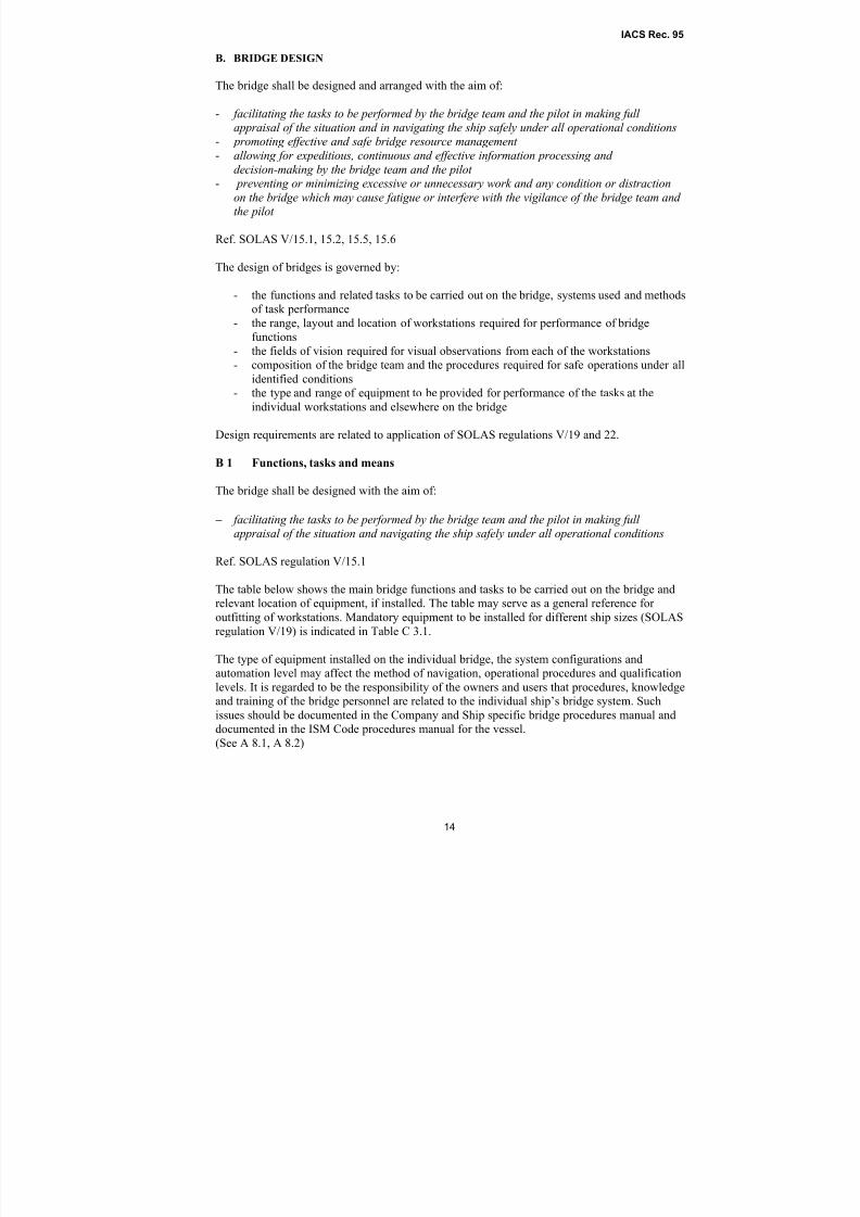
B. BRIDGE DESIGN
The bridge shall be designed and arranged with the aim of:
- facilitating the tasks to be performed by the bridge team and the pilot in making full appraisal of the situation and in navigating the ship safely under all operational conditions
- promoting effective and safe bridge resource management - allowing for expeditious, continuous and effective information processing and
decision-making by the bridge team and the pilot - preventing or minimizing excessive or unnecessary work and any condition or distraction
on the bridge which may cause fatigue or interfere with the vigilance of the bridge team and the pilot
Ref. SOLAS V/15.1, 15.2, 15.5, 15.6
The design of bridges is governed by:
- the functions and related tasks to be carried out on the bridge, systems used and methodsof task performance
- the range, layout and location of workstations required for performance of bridge
functions
- the fields of vision required for visual observations from each of the workstations
- composition of the bridge team and the procedures required for safe operations under all
identified conditions
- the type and range of equipment to be provided for performance of the tasks at the
individual workstations and elsewhere on the bridge
Design requirements are related to application of SOLAS regulations V/19 and 22.
B 1 Functions, tasks and means
The bridge shall be designed with the aim of:
− facilitating the tasks to be performed by the bridge team and the pilot in making full appraisal of the situation and navigating the ship safely under all operational conditions
Ref. SOLAS regulation V/15.1
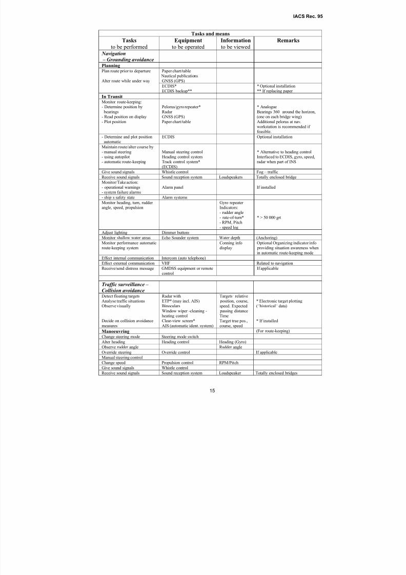
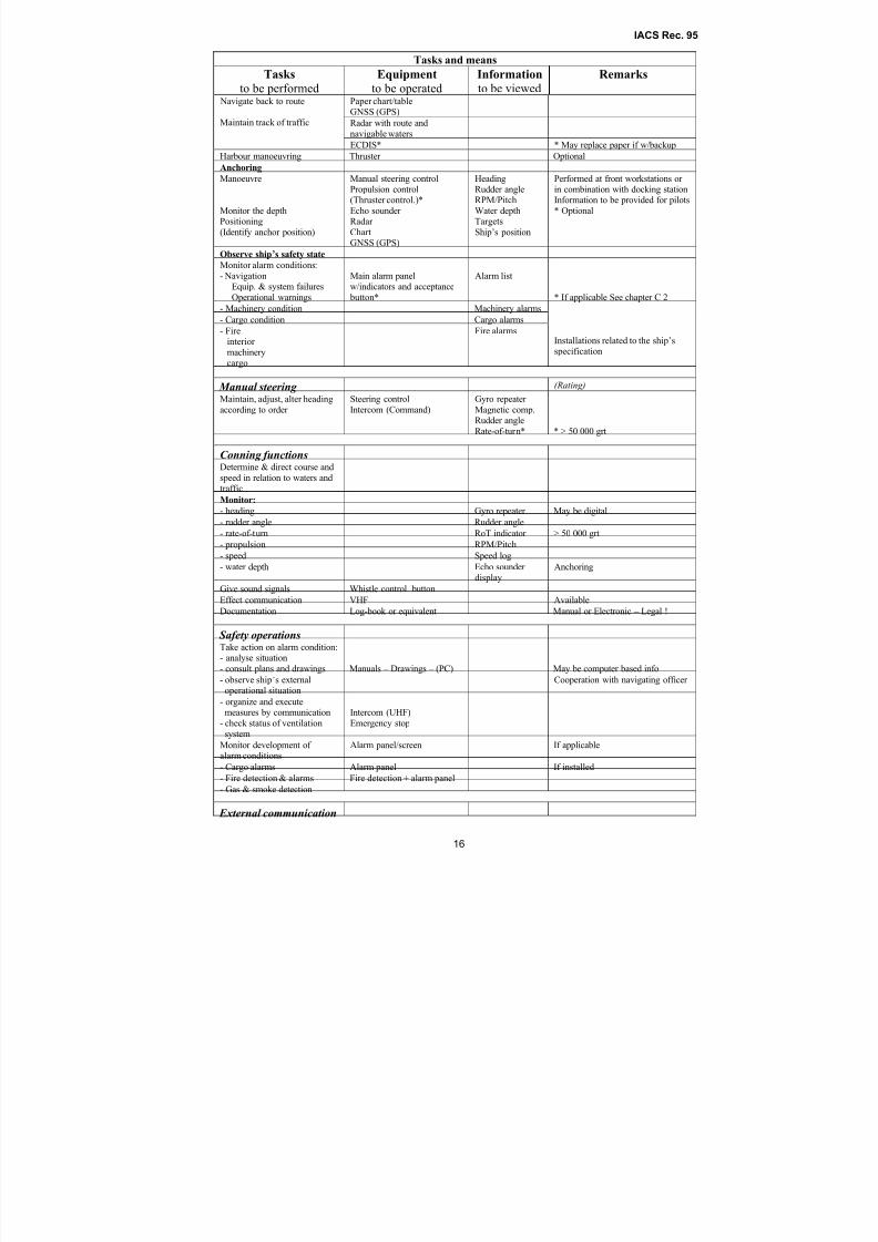
The table below shows the main bridge functions and tasks to be carried out on the bridge and
relevant location of equipment, if installed. The table may serve as a general reference for outfitting of workstations. Mandatory equipment to be installed for different ship sizes (SOLAS
regulation V/19) is indicated in Table C 3.1.
The type of equipment installed on the individual bridge, the system configurations and
automation level may affect the method of navigation, operational procedures and qualification
levels. It is regarded to be the responsibility of the owners and users that procedures, knowledge
and training of the bridge personnel are related to the individual ship’s bridge system. Such
issues should be documented in the Company and Ship specific bridge procedures manual and
documented in the ISM Code procedures manual for the vessel.
(See A 8.1, A 8.2)
8/2/2019 Iacs Bridge Design,Equipmenr Arrangement and Procedure.
http://slidepdf.com/reader/full/iacs-bridge-designequipmenr-arrangement-and-procedure 15/80
IACS Rec. 95
15
Tasks and means
Tasks
to be performedEquipment
to be operatedInformation
to be viewedRemarks
Navigation
– Grounding avoidance Planning
Paper chart/table Nautical publications
GNSS (GPS)
Plan route prior to departure
Alter route while under way
ECDIS*ECDIS backup**
* Optional installation** If replacing paper
In TransitMonitor route-keeping:- Determine position by
bearings- Read position on display
- Plot position
Pelorus/gyro repeater*
Radar GNSS (GPS)
Paper chart/table
* Analogue
Bearings 360˚ around the horizon,(one on each bridge wing)
Additional pelorus at nav.workstation is recommended if feasible.
- Determine and plot position
automatic
ECDIS Optional installation
Maintain route/alter course by
- manual steering- using autopilot- automatic route-keeping
Manual steering controlHeading control systemTrack control system*
(ECDIS)
* Alternative to heading controlInterfaced to ECDIS, gyro, speed,radar when part of INS
Give sound signals Whistle control Fog – traffic
Receive sound signals Sound reception system Loudspeakers Totally enclosed bridge
Monitor/Take action:
- operational warnings- system failure alarms
Alarm panel If installed
- ship’s safety state Alarm systems
Monitor heading, turn, rudder angle, speed, propulsion
Gyro repeater Indicators:
- rudder angle- rate-of-turn*- RPM, Pitch
- speed log
* > 50 000 grt
Adjust lighting Dimmer buttons
Monitor shallow water areas Echo Sounder system Water depth (Anchoring)
Monitor performance automaticroute-keeping system
Conning infodisplay
Optional Organizing indicator info providing situation awareness when
in automatic route-keeping mode
Effect internal communication Intercom (auto telephone)
Effect external communication VHF Related to navigation
Receive/send distress message GMDSS equipment or remote
control
If applicable
Traffic surveillance – Collision avoidanceDetect floating targetsAnalyse traffic situationsObserve visually
Decide on collision avoidance
measures
Radar withETP* (may incl. AIS)Binoculars
Window wiper -cleaning -heating controlClear-view screen*
AIS (automatic ident. system)
Targets’ relative position, course,
speed. Expected passing distanceTime
Target true pos.,course, speed
* Electronic target plotting(“historical” data)
* If installed
Manoeuvring (For route-keeping)
Change steering mode Steering mode switch
Alter heading Heading control Heading (Gyro)
Observe rudder angle Rudder angle
Override steering Override control If applicable
Manual steering control
Change speed Propulsion control RPM/Pitch
Give sound signals Whistle control
Receive sound signals Sound reception system Loudspeaker Totally enclosed bridges
8/2/2019 Iacs Bridge Design,Equipmenr Arrangement and Procedure.
http://slidepdf.com/reader/full/iacs-bridge-designequipmenr-arrangement-and-procedure 16/80
IACS Rec. 95
16
Tasks and means
Tasks
to be performedEquipment
to be operatedInformation
to be viewedRemarks
Paper chart/tableGNSS (GPS)
Radar with route and
navigable waters
Navigate back to route
Maintain track of traffic
ECDIS* * May replace paper if w/backup
Harbour manoeuvring Thruster OptionalAnchoring
Manoeuvre
Monitor the depthPositioning
(Identify anchor position)
Manual steering controlPropulsion control(Thruster control.)*
Echo sounder Radar
ChartGNSS (GPS)
HeadingRudder angleRPM/Pitch
Water depthTargets
Ship’s position
Performed at front workstations or in combination with docking stationInformation to be provided for pilots
* Optional
Observe ship’s safety state
Monitor alarm conditions:
- NavigationEquip. & system failures
Operational warnings
Main alarm panelw/indicators and acceptance
button*
Alarm list
* If applicable See chapter C 2
- Machinery condition Machinery alarms- Cargo condition Cargo alarms
- Fireinterior
machinerycargo
Fire alarmsInstallations related to the ship’sspecification
Manual steering (Rating)
Maintain, adjust, alter heading
according to order
Steering control
Intercom (Command)
Gyro repeater
Magnetic comp.Rudder angle
Rate-of-turn* * > 50 000 grt
Conning functionsDetermine & direct course and
speed in relation to waters andtraffic
Monitor:
- heading Gyro repeater May be digital
- rudder angle Rudder angle
- rate-of-turn RoT indicator > 50 000 grt
- propulsion RPM/Pitch
- speed Speed log
- water depth Echo sounder
display
Anchoring
Give sound signals Whistle control button
Effect communication VHF Available
Documentation Log-book or equivalent Manual or Electronic – Legal !
Safety operationsTake action on alarm condition:- analyse situation
- consult plans and drawings Manuals – Drawings – (PC) May be computer based info
- observe ship’s externaloperational situation
Cooperation with navigating officer
- organize and executemeasures by communication
- check status of ventilationsystem
Intercom (UHF)
Emergency stop
Monitor development of alarm conditions
Alarm panel/screen If applicable
- Cargo alarms Alarm panel If installed- Fire detection & alarms Fire detection + alarm panel
- Gas & smoke detection
External communication
8/2/2019 Iacs Bridge Design,Equipmenr Arrangement and Procedure.
http://slidepdf.com/reader/full/iacs-bridge-designequipmenr-arrangement-and-procedure 17/80
IACS Rec. 95
17
Tasks and means
Tasks
to be performedEquipment
to be operatedInformation
to be viewedRemarks
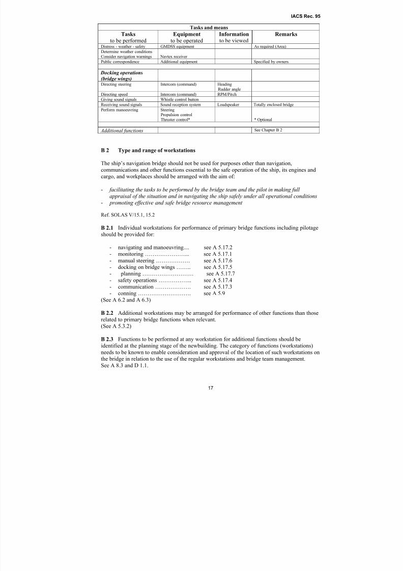
Distress - weather - safety GMDSS equipment As required (Area)
Determine weather conditionsConsider navigation warnings Navtex receiver
Public correspondence Additional equipment Specified by owners
Docking operations
(bridge wings) Directing steering Intercom (command) Heading
Rudder angle
Directing speed Intercom (command) RPM/Pitch
Giving sound signals Whistle control button
Receiving sound signals Sound reception system Loudspeaker Totally enclosed bridge
Perform manoeuvring SteeringPropulsion controlThruster control* * Optional
Additional functions See Chapter B 2
B 2 Type and range of workstations
The ship’s navigation bridge should not be used for purposes other than navigation,
communications and other functions essential to the safe operation of the ship, its engines and
cargo, and workplaces should be arranged with the aim of:
- facilitating the tasks to be performed by the bridge team and the pilot in making full appraisal of the situation and in navigating the ship safely under all operational conditions
- promoting effective and safe bridge resource management
Ref. SOLAS V/15.1, 15.2
B 2.1 Individual workstations for performance of primary bridge functions including pilotage
should be provided for:
- navigating and manoeuvring.... see A 5.17.2
- monitoring …………………... see A 5.17.1
- manual steering ……………… see A 5.17.6
- docking on bridge wings …….. see A 5.17.5
- planning ……………………… see A 5.17.7
- safety operations ……………... see A 5.17.4- communication ………………. see A 5.17.3
- conning ………………………. see A 5.9
(See A 6.2 and A 6.3)
B 2.2 Additional workstations may be arranged for performance of other functions than those
related to primary bridge functions when relevant.
(See A 5.3.2)
B 2.3 Functions to be performed at any workstation for additional functions should be
identified at the planning stage of the newbuilding. The category of functions (workstations)
needs to be known to enable consideration and approval of the location of such workstations onthe bridge in relation to the use of the regular workstations and bridge team management.
See A 8.3 and D 1.1.
8/2/2019 Iacs Bridge Design,Equipmenr Arrangement and Procedure.
http://slidepdf.com/reader/full/iacs-bridge-designequipmenr-arrangement-and-procedure 18/80
IACS Rec. 95
18
Note:
The main types of additional bridge workstations may be divided into three distinct categories based on
purpose and functions and whether they are to be operated by the watch officer or not:
A. Workstations for functions regarded related to operation of the ship, its engines and cargo:
a) to be monitored and controlled by the officer of the watch
b) to be used by other personnel than the officer of the watch
B. Workstations for functions not regarded essential to safe operation of the ship and to be used by
other personnel than the watch officer, but located on the bridge for practical reasons.
Disregarding the type of additional functions to be carried out, when such functions are
included as part of the responsibility of the officer of the watch, it must be taken into
consideration that additional functions will always have a lower priority than performance of
primary functions.
See B 5.14 – B 5.16.
See Guidance note, Annex A.
B 3 Working environment
The bridge shall be designed and arranged with the aim of:
- preventing or minimizing excessive or unnecessary work and any condition or distractionon the bridge which may cause fatigue or interfere with the vigilance of the bridge team and
the pilot
Ref. SOLAS V/15.6
Internal environmental conditions on the bridge that may affect human performance are:
- temperature
- humidity
- ventilation
- noise
- vibration
- illumination and type of lighting
- glare and reflection
- interior colours
- occupational safety
B 3.1 The enclosed bridge or wheelhouse should be provided with air conditioning or a
ventilation system for regulation of temperature and humidity helping to avoid that the thermal
response of the body affects efficient task performance under various operating conditions.
Note:
Temperatures which are not less than 18˚C in cold climates and do not exceed 27˚C in tropical climates
are regarded feasible for normal bridge watch conditions. These temperatures are based on relatively
still air and normal air humidity (40% – 60%). Higher temperatures are acceptable if airflow is increased
and humidity is lowered.
B 3.2 Ventilation system with suitable air flow velocity and rate of air circulation should be
provided. Direction of air flow from air conditioning and heating systems towards workplaces
should be avoided.
8/2/2019 Iacs Bridge Design,Equipmenr Arrangement and Procedure.
http://slidepdf.com/reader/full/iacs-bridge-designequipmenr-arrangement-and-procedure 19/80
IACS Rec. 95
19
B 3.3 Excessive levels of noise interfering with voice communication, causing fatigue and
degrading overall system reliability, should be avoided.
See Guidance note, Annex A.
B 3.4 Vibrations when the ship is at normal transit speeds should not affect the reading of
indicators or the performance of bridge equipment.
B 3.5 Lighting arranged for adjustment of illumination and direction of light should be
provided at all workplaces and lighting should always be arranged at entrances and exits of
enclosed workplace areas. Light controls should be visible in darkness. The illumination
brightness should be sufficient for safe performance of the tasks and possible to dim down to
zero. White ceiling lights do not require dimming facilities . B 3.6 Lighting that may be required for continuous operations during darkness and in
entrances to the bridge should be of a type that provides the least impact on night vision, with
adjustable brightness to suit the operations and ease visual adaptation to darkness.
See Guidance note, Annex A.
B 3.7 It should be possible to dim equipment displays and indicators providing information to
individual workstations and the lighting covering the workstation area, at the workstation in
use.
B 3.8 Light sources should be arranged and located in a way that prevents glare, stray image
and mirror effects in bridge windows and deckhead areas above workstations.
See Guidance note, Annex A.
B 3.9 To reduce the risk of personnel injury during bridge operations,
- the wheelhouse floor, bridge wings and upper bridge decks should have non-slip
surfaces;
- hand- or grab-rails should be installed as required at workstations, passageways and
entrances, enabling personnel to move and stand safely when the ship is rolling and
pitching in heavy weather;
- chair deck rails installed at workstations should be provided with anti-trip skirting board
or be flush mounted;
- stairway openings should be protected if not sufficiently lit or otherwise indicated
during darkness;
- sharp edges or protuberances which could cause injury to personnel should be avoided;
- deck mounted hatches and manhole covers set into the wheelhouse, bridge wings andupper bridge decks should be flush fitting to remove trip hazards.
B 3.10 Personnel safety equipment to be stored on the bridge should be clearly marked and
easily accessible.
B 3.11 All portable items, including safety equipment, tools, lights and pencils should be stored
at dedicated places.
8/2/2019 Iacs Bridge Design,Equipmenr Arrangement and Procedure.
http://slidepdf.com/reader/full/iacs-bridge-designequipmenr-arrangement-and-procedure 20/80
IACS Rec. 95
20
B 4 Bridge passageways
The bridge should be designed and arranged with the aim of:
- promoting effective and safe bridge resource management
Ref. SOLAS V/15.2
Bridge passageways should facilitate the expected movement of the bridge team between
individual workstations, bridge entrances, exits and windows in carrying out the bridge tasks
safely and effectively including the maintenance of equipment.
B 4.1 A clear route across the wheelhouse, from bridge wing to bridge wing for two persons to
pass each other, should be provided. The width of the passageway should preferably be 1200
mm and not less than 700 mm at any single point of obstruction and allow easy access to side
doors.
B 4.2 The distance between separate workstation areas should be sufficient to allowunobstructed passage for persons not working at the stations. The width of such passageways
should not be less than 700 mm, allowing for a persons sitting or standing at their workstations.
B 4.3 The distance from the bridge front bulkhead, or from any console and installation placed
against the front bulkhead to any console or installation placed away from the bridge front,
should be sufficient for one person to pass a stationary person. The width should preferably be
1000 mm and not less than 800 mm.
B 4.4 The distance between bridge wing consoles, if installed and bulkheads should be as little
as possible for easy operation of controls from both a position behind and beside the console
giving optimum view of the ship’s side and the mooring operations, but wide enough for one person to pass the console. The width of the passageway should preferably be 600 mm.
Note:
The Panama Canal Commission (PCC) requires that a minimum of 1 metre clearance from consoles or
obstructions shall be provided from the forward to aft portions of the bridge wing ends. Special requests
for relaxation of this requirement may be considered on a case-by-case basis.
B 4.5 The clear deckhead height in the wheelhouse should take into account the installation of
deckhead panels and instruments as well as the height of door openings required for easy
entrance to the wheelhouse. The following clear heights for unobstructed passage should be
provided:
a) The clear height between the bridge deck surface covering and the underside of the deck
head covering should be at least 2250 mm.
b) The lower edge of deck head-mounted equipment in open areas and passageways, as well
as the upper edge of door openings to bridge wings and other open deck areas should be at
least 2100 mm above the deck.
c) The height of entrances and doors to the wheelhouse from adjacent passageways should
not be less than 2000 mm.
B 4.6 All wheelhouse doors should be operable with one hand. Bridge wing doors should not
be self closing and means should be provided to hold the doors open.
8/2/2019 Iacs Bridge Design,Equipmenr Arrangement and Procedure.
http://slidepdf.com/reader/full/iacs-bridge-designequipmenr-arrangement-and-procedure 21/80
IACS Rec. 95
21
B 5 Workstation arrangements and required fields of vision
The bridge should be designed and arranged with the aim of:
- facilitating the tasks to be performed by the bridge team and the pilot in making full
appraisal of the situation and in navigating the ship safely under all operational conditions- promoting effective and safe bridge resource management - allowing for expeditious, continuous and effective information processing and
decision-making by the bridge team and the pilot - preventing or minimizing excessive or unnecessary work and any condition or distraction
on the bridge which may cause fatigue or interfere with the vigilance of the bridge team and the pilot
Ref. SOLAS regulations V/15.1, 15.2, 15.3, 15.5, 15.6
The workstations for primary bridge functions should be arranged to serve their functions under
all operating conditions and different manning of the bridge and provide the fields of visionrequired for visual observations and easy cooperation between bridge personnel, promoting
effective and safe bridge resource management.
B 5.1 Workstations for navigating and manoeuvring and for monitoring should be arranged
within an area spacious enough for two persons to carry out the tasks in close cooperation, but
sufficiently close together to enable the watch officer to control and safely carry out all the
tasks from one working area under normal operating conditions.
See Guidance note, Annex A.
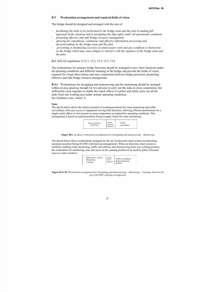
Note:
The sketch below shows the relative location of working positions for route monitoring and trafficsurveillance with easy access to equipment serving both functions, allowing efficient performance by a
single watch officer or two persons in close cooperation as required by operating conditions. This
arrangement is based on manual position-fixing in paper charts for route monitoring:
Figure B5.1 A: Basic workstation arrangement for Navigating and manoeuvring – Monitoring
The sketch below shows workstations arranged for the use of electronic chart system incorporating
automatic position-fixing (ECDIS with back-up arrangement). When an electronic chart system isinstalled, enabling route monitoring, traffic surveillance and manoeuvring from one working position,
the workstation for monitoring, may also serve as the conning position to be used by pilots if located
close to centre windows.
Figure B 5.1 B: Workstation arrangement for Navigating and manoeuvring – Monitoring – Conning, based on theuse of ECDIS w/backup arrangement
AlarmsCommun.
Manoeuvr.
Route monitoring
Monitoring
Traffic
surveillance
AlarmsComm.
Manoeuvr.
Back-up nav. system
Monitoring
Conning
Traffic surveillanceRoute monitoring
ECDIS
8/2/2019 Iacs Bridge Design,Equipmenr Arrangement and Procedure.
http://slidepdf.com/reader/full/iacs-bridge-designequipmenr-arrangement-and-procedure 22/80
IACS Rec. 95
22
B 5.2 The working positions at workstations for performance of route monitoring and traffic
surveillance should be arranged for working in standing as well as seated position with
optimum field of vision.
B 5.3 The view of the sea surface, blind sector limitations and the field of vision, specified in
SOLAS regulation V/22 “Navigation bridge visibility” to facilitate the tasks to be performed by
the bridge team and the pilot in making full appraisal of the situation and in navigating the ship
safely under all operational conditions as specified in SOLAS regulation V/15.1 should be
provided at bridge workplaces which include the task of conning,
- enabling the bridge team and the pilot to have convenient and continuous access to
essential information (Reg.V/15.3) by visual observations;- promoting effective and safe resource management (Reg.V/15.2);
- allowing for expeditious, continuous and effective information processing (Reg.V/15.5).
B 5.3.1 It should be possible to observe all objects of interest for the navigation such as ships
and lighthouses, in any direction from inside the wheelhouse by providing a horizontal field of
vision to the horizon of 360°.
See Guidance note, Annex A.
B 5.3.2 For safe performance of bridge functions, including conning, it should be possible for
the bridge team and the pilot to eliminate the effect of blind sectors outside the wheelhouse by
moving within the area of each their dedicated workplace and to eliminate blind sectors caused by divisions between windows without leaving the working position at the chair.
B 5.4 A conning position, the workstation for monitoring and the workstation for navigating
and manoeuvring should provide a commanding view enabling maintenance of visual traffic
surveillance for safe conning of the ship by the officer of the watch and the pilot, requiring that:
- the view of the sea surface is not obscured by more than two ship lengths (2 x LOA), or
500m, whichever is less, forward of the bow to 10° on either side under all conditions of
draught, trim and deck cargo.
- the horizontal field of vision extends over an arc of not less than 225° - that is from
right ahead to not less than 22.5° abaft the beam on either side of the ship. See Guidance note, Annex A.
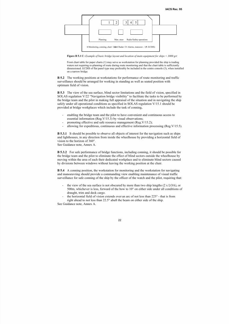
Figure B 5.1 C: Example of basic bridge layout and location of main equipment for ships < 3000 grt
Front chart table for paper charts (1) may serve as workstation for planning provided the ship is trading
waters not requiring re-planning of route during route monitoring and that the chart table is sufficientlydimensioned. ECDIS of flat panel type may preferably be included in the centre console (3), when installed
on a narrow bridge.
Planning Man. steer Radio/Safety operations
54321
1:Monitoring, conning, chart / 2&4: Radar / 3: Alarms, manoeuv. / (5: ECDIS)
8/2/2019 Iacs Bridge Design,Equipmenr Arrangement and Procedure.
http://slidepdf.com/reader/full/iacs-bridge-designequipmenr-arrangement-and-procedure 23/80
IACS Rec. 95
23
Note:
For ships to be navigating narrow waters and harbour entrances requiring exact course-keeping, the
owners should consider the need for the bridge to provide the field of vision as required for using lights
in line astern of the ship as a visual reference from the navigating and manoeuvring workstation, and
include this requirement in the building specification.
B 5.5 The commanding view required for safe conning shall be complied with at a position
equipped as required by Reg.V/19.2.5.4, providing a close view of the sea surface for safedirecting of the steering and speed in narrow canals and buoy lanes.
B 5.5.1 A workstation for monitoring located close to the forward centre window, not required
by the ship’s personnel during pilotage may serve as the conning position specified in B 5.5.
Note:
a) The Panama Canal Commission (PCC) requires that the conning position be located “directly behind
and next to” the centre front window and the nearest window thereto on each side that provides a
clear and unobstructed view ahead for conning during canal transit. A minimum of 1 metre
clearance from consoles or obstructions should be provided. Special requests for relaxation of this
requirement may be considered on a case-by-case basis.
b) PCC requires that the conning position shall provide a view of the sea surface forward of the bow
from 1.5 ship’s length when at ballast load line and 1 ship’s length at full load line.
B 5.6 Workstations for the functions of monitoring and navigation equipped with radar and
navigational chart should provide a commanding view in accordance with the requirements for
safe conning, to be used by the ship’s officers and for serving as additional conning stations for
alternative use by the pilot when equipment installed at the workstations is required for
additional information and the view of the sea surface close to both sides of the ship’s bow is
not required.
Note:The viewing point to be used for calculation of the required view and fields of vision from a conning
position at the front bridge window should be the working position 75 cm aft of the window and the
working position 35 cm aft of the radar consoles, whether the workstations are equipped with a chair or
not. This also applies when a workstation with radar is located at a front window also serving as the
position for conning.
B 5.7 Workstations for monitoring, navigating and manoeuvring should provide the required
horizontal fields of vision from a seated working position and should not be located directly
behind large masts, cranes, etc. which obstruct the view right ahead from the workstation.
See Guidance note, Annex A.
B 5.8 No blind sector caused by obstructions outside of the wheelhouse forward of the beam
which hampers the view of the sea surface as seen from a conning position and the workstation
for navigating and manoeuvring, shall exceed 10˚. The clear sectors between blind sectors shall
be at least 5˚. Within a sector from right ahead to at least 10˚ on either side, each individual
blind sector shall not exceed 5˚. The total arc of blind sectors forward of the beam shall not
exceed 20˚.
B 5.8.1 The total arc of additional blind sectors between the beam and 22.5° abaft the beam on
either side should not exceed 10°, allowing a total of 30° within the required total field of vision
of 225°. To ensure a total field of vision of 225° for proper look-out and safe conning, a clear
sector of at least 5° shall extend from 22.5º abaft the beam and forward on either side of theship. See also B 5.5.
See Guidance note, Annex A.
8/2/2019 Iacs Bridge Design,Equipmenr Arrangement and Procedure.
http://slidepdf.com/reader/full/iacs-bridge-designequipmenr-arrangement-and-procedure 24/80
IACS Rec. 95
24
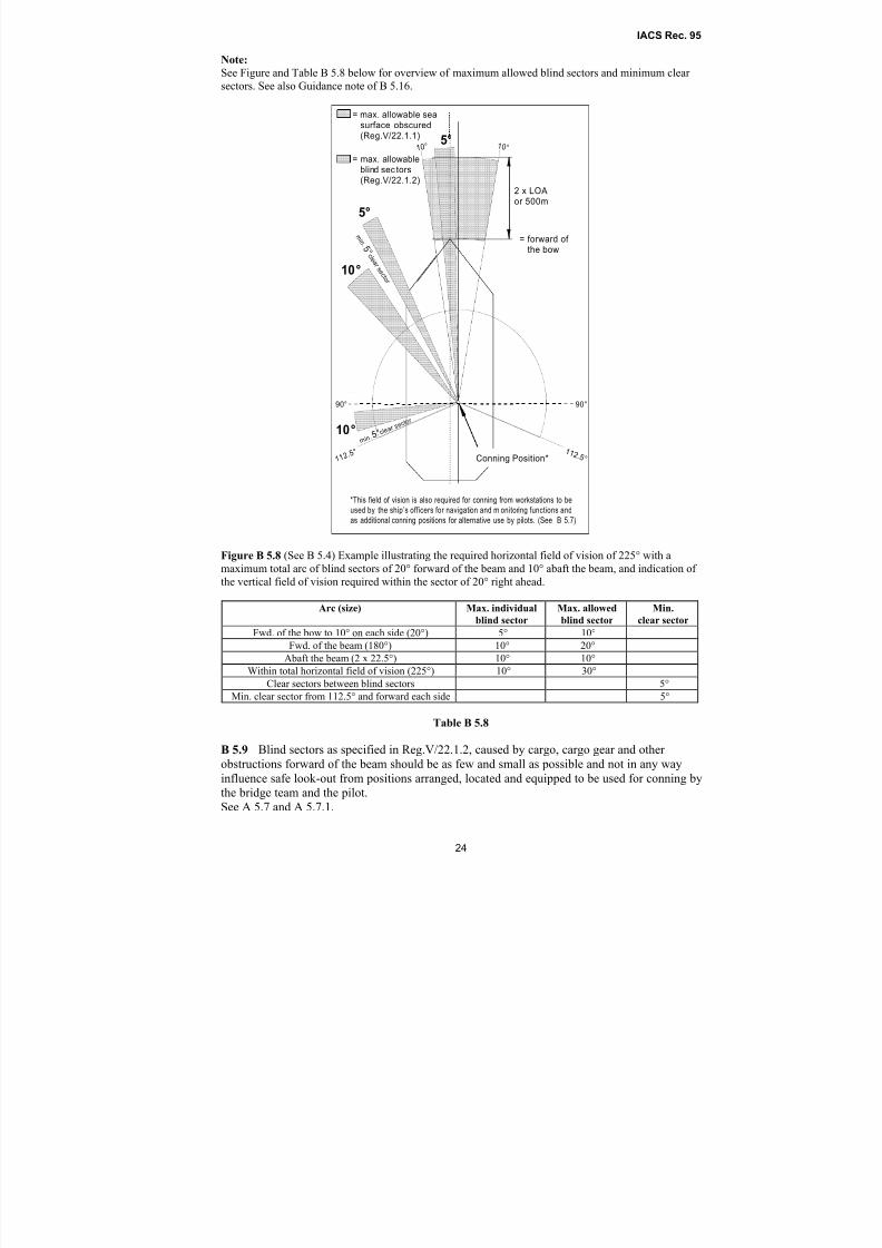
Note:
See Figure and Table B 5.8 below for overview of maximum allowed blind sectors and minimum clear
sectors. See also Guidance note of B 5.16.
10°
10°
1 1 2. 5
° 1 1 2 .5 °
1 0 ° 10 °
= max. allowableblind sec tors(Reg.V/22.1.2)
5°
m i n . 5 ° c l e a
r s e c t o r
= forward of the bow
2 x LOAor 500m
Conning Position*
m i n. 5 °
c l e a r
s e c t o r
= max. allowable seasurface obscured(Reg.V/22.1.1)
*This field of vision is also required for conning from workstations to be
used by the ship’s officers for navigation and m onitoring functions and
as additional conning positions for alternative use by pilots. (See B 5.7)
5°
90° 90°
Figure B 5.8 (See B 5.4) Example illustrating the required horizontal field of vision of 225° with a
maximum total arc of blind sectors of 20° forward of the beam and 10° abaft the beam, and indication of
the vertical field of vision required within the sector of 20° right ahead.
Arc (size) Max. individual
blind sector
Max. allowed
blind sector
Min.
clear sector
Fwd. of the bow to 10° on each side (20°) 5° 10°
Fwd. of the beam (180°) 10° 20°
Abaft the beam (2 x 22.5°) 10° 10°
Within total horizontal field of vision (225°) 10° 30°
Clear sectors between blind sectors 5°
Min. clear sector from 112.5° and forward each side 5°
Table B 5.8
B 5.9 Blind sectors as specified in Reg.V/22.1.2, caused by cargo, cargo gear and other
obstructions forward of the beam should be as few and small as possible and not in any way
influence safe look-out from positions arranged, located and equipped to be used for conning by
the bridge team and the pilot.
See A 5.7 and A 5.7.1.
8/2/2019 Iacs Bridge Design,Equipmenr Arrangement and Procedure.
http://slidepdf.com/reader/full/iacs-bridge-designequipmenr-arrangement-and-procedure 25/80
IACS Rec. 95
25
B 5.9.1 Only blind sectors that cannot be avoided due to unusual structure and size of the
cargo units to be stowed on deck and fixed structures regarded a prerequisite for the
performance of specific ship functions and required for the purpose of safe operations of cargo
and the ship may be included in the blind sector limits allowed by SOLAS regulation V/22,
taking into account B 5.3.2 of this Recommendation.
Note:
Composition of the bridge team as required to ensure continuous look-out and safe conning by
eliminating the effect of additional blind sectors caused by carriage of uncommon cargo on deck not
enabling conformance with B 5.3.2 is considered the responsibility of the captain and the officer in
charge of the navigational watch. Relevant considerations may need acceptance by the flag state
Administration.
B 5.9.2 Regular cargo (such as cargo container units) stacked on deck in the field of vision
forward of the beam should not obstruct the view of the sea surface at the horizon as seen from
positions arranged, located and equipped to be used for conning by the bridge team and the
pilot. See A 5.7 and A 5.7.1.
B 5.9.3 The height of stacked cargo should not exceed the line of sight of the sea surfaceforward of the bow specified in Reg.V/22.1.1.
B 5.10 The workstation for manual steering should preferably be located on the ship’s centre
line and should not interfere with the functions to be performed by the officer of the watch. The
steering position should provide a forward field of vision not less than 60˚ to each side. If large
masts, cranes, etc., obstruct the view in front of the workstation, it should be located some
distance to starboard of the centre line, sufficiently to obtain a clear view ahead. It is not
required to arrange the manual steering stand to be used in seated position.
B 5.11 When the workstation for manual steering is located off centre, or the bow of the ship
cannot be seen from the steering position, special steering references (sighting marks) should beinstalled forward of the steering position. The steering references should be installed in line
parallel to the ship’s centre line for use by day and by night.
B 5.12 The ship’s side should be visible from the bridge wing. Equipment for docking
operations from the bridge wings, or a workstation console if installed, should be located to
enable visual observations required for safe manoeuvring of the ship, monitoring of tug and
mooring operations and should provide a field of vision from not less than 45˚ on opposite bow
to right astern from the working position as shown in Figure A.
B 5.13 There should be a close approach access to at least one front window providing the viewof the area in front of the accommodation superstructure. The access should not interfere with
the use of a conning position arranged for pilots at the front window.
B 5.14 Workstations for additional functions which are of the category to be monitored and
controlled by the watch officer as specified in B 2.3-A(a) should provide the field of vision
required to maintain efficient look-out and enable monitoring of the ship’s heading and rudder
angle. (See also last part of the guidance note to B 5.5).
B 5.15 The location of a workstation for additional functions regarded essential for safe
operation of the ship and to be used by other personnel than the watch officer should not in any
way influence the performance of primary bridge functions.
B 5.16 Workstations for additional functions not essential to the safe operation of the ship, its
engines and cargo, or furniture arranged for meetings or relaxation inside the wheelhouse
8/2/2019 Iacs Bridge Design,Equipmenr Arrangement and Procedure.
http://slidepdf.com/reader/full/iacs-bridge-designequipmenr-arrangement-and-procedure 26/80
IACS Rec. 95
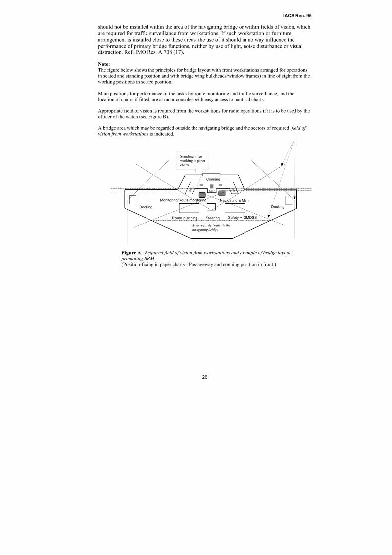
26
should not be installed within the area of the navigating bridge or within fields of vision, which
are required for traffic surveillance from workstations. If such workstation or furniture
arrangement is installed close to these areas, the use of it should in no way influence the
performance of primary bridge functions, neither by use of light, noise disturbance or visual
distraction. Ref. IMO Res. A.708 (17).
Note:
The figure below shows the principles for bridge layout with front workstations arranged for operationsin seated and standing position and with bridge wing bulkheads/window frames) in line of sight from the
working positions in seated position.
Main positions for performance of the tasks for route monitoring and traffic surveillance, and the
location of chairs if fitted, are at radar consoles with easy access to nautical charts.
Appropriate field of vision is required from the workstations for radio operations if it is to be used by the
officer of the watch (see Figure B).
A bridge area which may be regarded outside the navigating bridge and the sectors of required field of
vision from workstations is indicated.
Figure A Required field of vision from workstations and example of bridge layout
promoting BRM .
(Position-fixing in paper charts - Passageway and conning position in front.)
Area regarded outside the
navigating bridge
Man
Standing when
working in paper
charts
Navigating & Man.Monitoring/Route monitoring
SteeringRoute planning Safety - GMDSS
Docking Docking
Conning
8/2/2019 Iacs Bridge Design,Equipmenr Arrangement and Procedure.
http://slidepdf.com/reader/full/iacs-bridge-designequipmenr-arrangement-and-procedure 27/80
IACS Rec. 95
27
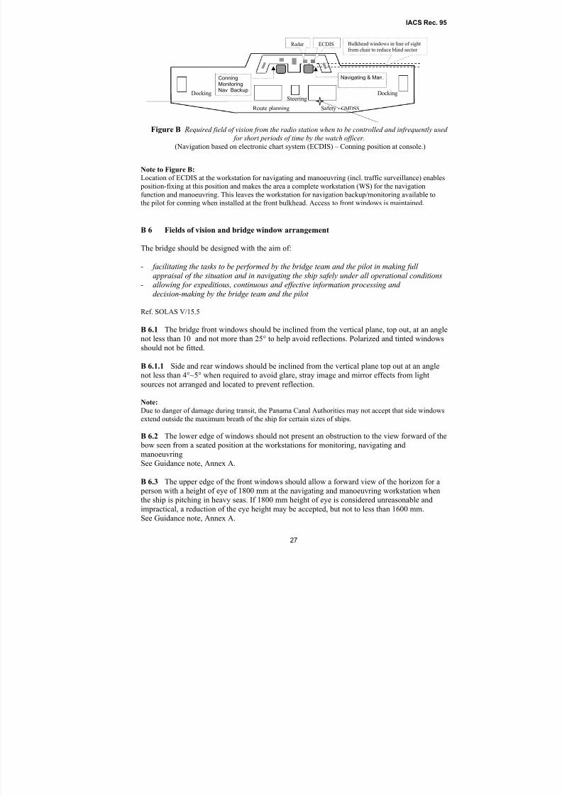
Note to Figure B:
Location of ECDIS at the workstation for navigating and manoeuvring (incl. traffic surveillance) enables
position-fixing at this position and makes the area a complete workstation (WS) for the navigation
function and manoeuvring. This leaves the workstation for navigation backup/monitoring available tothe pilot for conning when installed at the front bulkhead. Access to front windows is maintained.
B 6 Fields of vision and bridge window arrangement
The bridge should be designed with the aim of:
- facilitating the tasks to be performed by the bridge team and the pilot in making full
appraisal of the situation and in navigating the ship safely under all operational conditions- allowing for expeditious, continuous and effective information processing and
decision-making by the bridge team and the pilot
Ref. SOLAS V/15.5
B 6.1 The bridge front windows should be inclined from the vertical plane, top out, at an angle
not less than 10˚ and not more than 25° to help avoid reflections. Polarized and tinted windows
should not be fitted.
B 6.1.1 Side and rear windows should be inclined from the vertical plane top out at an angle
not less than 4°~5° when required to avoid glare, stray image and mirror effects from light
sources not arranged and located to prevent reflection.
Note:
Due to danger of damage during transit, the Panama Canal Authorities may not accept that side windows
extend outside the maximum breath of the ship for certain sizes of ships.
B 6.2 The lower edge of windows should not present an obstruction to the view forward of the
bow seen from a seated position at the workstations for monitoring, navigating and
manoeuvring
See Guidance note, Annex A.
B 6.3 The upper edge of the front windows should allow a forward view of the horizon for a
person with a height of eye of 1800 mm at the navigating and manoeuvring workstation whenthe ship is pitching in heavy seas. If 1800 mm height of eye is considered unreasonable and
impractical, a reduction of the eye height may be accepted, but not to less than 1600 mm.
See Guidance note, Annex A.
Figure B Required field of vision from the radio station when to be controlled and infrequently used
for short periods of time by the watch officer.
(Navigation based on electronic chart system (ECDIS) – Conning position at console.)
Navigating & Man.
Steering
Route planning Safety - GMDSS
Docking Docking
ConningMonitoringNav Backup
Radar ECDIS Bulkhead windows in line of sightfrom chair to reduce blind sector
8/2/2019 Iacs Bridge Design,Equipmenr Arrangement and Procedure.
http://slidepdf.com/reader/full/iacs-bridge-designequipmenr-arrangement-and-procedure 28/80
IACS Rec. 95
28
Note:
The minimum height of the upper edge of front windows of 2000 mm may be accepted even if the
vertical field of vision is less than 5° above the horizontal line from a standing height of 1800 mm,
provided adequate chairs are installed for easy viewing from sitting position at the workstations when
the ship is pitching in heavy seas and there is a passageway in front of the workstations enabling
appropriate view from standing position.
B 6.4 Framing between windows should be kept to a minimum and not be installed
immediately forward of any workstation or in the centreline. If stiffeners between windows
should be covered, this should not cause further obstruction of the view.
See Guidance note, Annex A.
B 6.5 A clear view through at least two of the navigation bridge front windows and,
depending on the bridge configuration an additional number of clear-view windows should be
provided at all times, regardless of weather conditions, in accordance with Reg.V/22.1.9.4. The
windows providing a clear view should include windows within the field of vision required for
conning, seen from the viewing point at workplaces arranged to be used by the bridge team and
the pilot for conning.
B 6.5.1 Sunscreens of roller blind type with minimum colour distortion, heavy duty blade type
wipers,* fresh water window washing and efficient de-icing and de-misting system or other
means should be installed as required to help maintaining a clear view through windows. A
catwalk or other means should be provided if required to help maintenance of window wipers
and manual cleaning of bridge front windows. See. 2.6.1, UI V/22.
Technical systems installed should comply with appropriate ISO standards*
* ISO 17899 Marine electric window wipers.
B 6.5.2 Clear view screens, if provided, should not be installed in windows in front of themanual steering position and radars, and not more than one to each side of the centre line,
available for conning.
B 7 Workstation layout, consoles and chair arrangement
The configuration of workstations and consoles should provide a workplace for rational and
user-friendly placing of equipment, with the aim of:
- facilitating the tasks to be performed by the bridge team and the pilot in making full
appraisal of the situation and in navigating the ship safely under all operational conditions- promoting effective and safe bridge resource management - enabling the bridge team and the pilot to have convenient and continuous access to
essential information- allowing for expeditious, continuous and effective information processing and decision-
making by the bridge team and the pilot - preventing, or minimizing, excessive or unnecessary work and any condition or distractions
on the bridge which may cause fatigue or interfere with the vigilance of the bridge team and
the pilot
Ref. SOLAS V/15.1, 15.2, 15.3, 15.5, 15.6
A functional workstation designed in accordance with the established overall operational and
ergonomic requirements must provide:
8/2/2019 Iacs Bridge Design,Equipmenr Arrangement and Procedure.
http://slidepdf.com/reader/full/iacs-bridge-designequipmenr-arrangement-and-procedure 29/80
IACS Rec. 95
29
- a sufficient area for performance of the tasks to be carried out by the number of people that
may be required to attend
- consoles designed for operations at specific workstations in standing and seated position,
o enabling installation of equipment to be within reach from the working position
o avoiding obstruction of the view through bridge windows from seated position
- chairs suiting ergonomic requirements for efficient use of installed equipment and
maintenance of fields of vision if chairs are to be installed.
B 7.1 The workstation for navigating and manoeuvring should have working positions for
route monitoring, change of course and speed and traffic surveillance as close as possible for
efficient use by the officer of the watch, but also enabling the tasks to be performed by two
navigators in close co-operation.
See Guidance note, Annex A.
B 7.2 Consoles should principally be divided into two areas, when applicable:
- a vertical (slanting) part for location of information displays to be easily readable
- a horizontal part (desktop) for controls, switches and buttons to be within easy reach
from the working position
B 7.3 The height of console desktops at the workplaces for navigation, manoeuvring, traffic
surveillance and monitoring should enable easy use of equipment required for safe performance
of the tasks to be performed from both standing and sitting position.
B 7.3.1 To provide a functional reach from standing position, the height of console desktops
above bridge deck surface, equipped with means for operation, should preferably be 800 mm
and not less than 750 mm, sloping forward to a height of 950 mm and not less than 900 mm for consoles having a depth of 800 mm from the working position. The height of desktops for
frequent use of paper charts for route monitoring from standing position should preferably be
900 mm and not less than 800 mm. To provide easy operation of controls from sitting position,
it should be possible to adjust the height of the seat to allow an elbow height 50 mm higher than
the console desktop.
Note:
a. The type of work, means to be used and frequency of use during operations need to be taken into
consideration when placing the means in relation to working positions.
b. The indication of preferable heights does not exclude acceptance of other dimensions when justified,
provided other requirements and the overall bridge functionality are not adversely affected.c. The height of consoles for route planning in paper charts should preferably be 950 mm and not less
than 900 mm.
B 7.4 The console in front of a seated working position should provide sufficient leg room as
required to ease the reach of equipment and controls to be used.
See Guidance note, Annex A.
B 7.5 Console configurations and location of displays should aim at providing the user with
the information required for performance of main functions at his workstation within a viewing
angle from right ahead to 95° to each side.
B 7.6 The consoles forming the front workstations should not be higher than required for
efficient use in standing position and should not obstruct the fields of vision over the lower
edge windows in front of the workstation from sitting position.
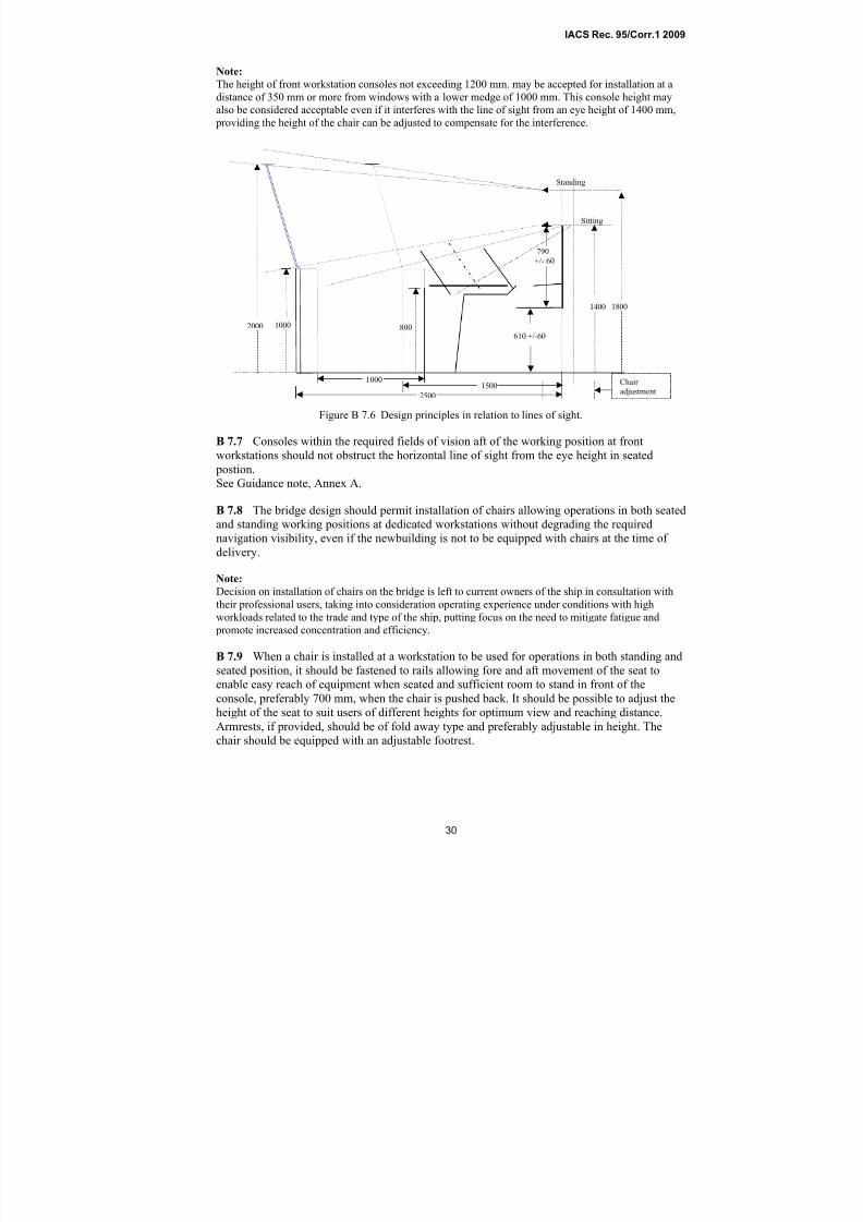
8/2/2019 Iacs Bridge Design,Equipmenr Arrangement and Procedure.
http://slidepdf.com/reader/full/iacs-bridge-designequipmenr-arrangement-and-procedure 30/80
IACS Rec. 95
30
Note:
The height of front workstation consoles not exceeding 1200 mm. may be accepted for installation at a
distance of 350 mm or more from windows with a lower medge of 1000 mm. This console height may
also be considered acceptable even if it interferes with the line of sight from an eye height of 1400 mm,
providing the height of the chair can be adjusted to compensate for the interference.
Figure B 7.6 Design principles in relation to lines of sight.
B 7.7 Consoles within the required fields of vision aft of the working position at front
workstations should not obstruct the horizontal line of sight from the eye height in seated postion.
See Guidance note, Annex A.
B 7.8 The bridge design should permit installation of chairs allowing operations in both seated
and standing working positions at dedicated workstations without degrading the required
navigation visibility, even if the newbuilding is not to be equipped with chairs at the time of
delivery.
Note:
Decision on installation of chairs on the bridge is left to current owners of the ship in consultation with
their professional users, taking into consideration operating experience under conditions with highworkloads related to the trade and type of the ship, putting focus on the need to mitigate fatigue and
promote increased concentration and efficiency.
B 7.9 When a chair is installed at a workstation to be used for operations in both standing and
seated position, it should be fastened to rails allowing fore and aft movement of the seat to
enable easy reach of equipment when seated and sufficient room to stand in front of the
console, preferably 700 mm, when the chair is pushed back. It should be possible to adjust the
height of the seat to suit users of different heights for optimum view and reaching distance.
Armrests, if provided, should be of fold away type and preferably adjustable in height. The
chair should be equipped with an adjustable footrest.
790
+/- 60
1000 Chair
adjustment
1000
Sitting
Standing
1500
2500
2000
1400 1800
800610 +/-60
IACS Rec. 95/Corr.1 2009
8/2/2019 Iacs Bridge Design,Equipmenr Arrangement and Procedure.
http://slidepdf.com/reader/full/iacs-bridge-designequipmenr-arrangement-and-procedure 31/80
IACS Rec. 95
31
C. DESIGN AND ARRANGEMENT OF NAVIGATIONAL SYSTEMS AND EQUIPMENT
Navigational systems and equipment should be designed with the aim of:
- ……..presenting the information in a clear and unambiguous manner, using standardized symbols and coding systems for controls and displays
- indicating the operational status of automated functions and integrated components,
systems and/or sub-systems- minimizing the risk of human error and detecting such error if it occurs, through
monitoring and alarm systems, in time for the bridge team and the pilot to take appropriate
action
Ref. SOLAS V/15.3, 15.4, 15.7
and be arranged with the aim of:
- facilitating the tasks to be performed by the bridge team and the pilot in making full
appraisal of the situation and in navigating the ship safely under all operational conditions- enabling the bridge team and the pilot to have convenient and continuous access to
essential information- allowing for expeditious, continuous and effective information processing and
decision-making by the bridge team and the pilot
Ref. SOLAS V/15.1, 15.3, 15.5
The basic design of navigation systems and equipment allowed to be used for decision-making
related to safety of navigation is governed by functional and technical requirements as well as
ergonomic and human-machine interface criteria expressed in the performance standard for
General requirements for shipborne radio equipment and electronic navigation aids* and
individual IMO equipment performance standards.
Compliance is verified by tests carried out in accordance with appropriate IEC or ISO test
standards endorsed by IMO and documented by type approval certificates issued by the flag
state Administration. Choice of type approved equipment is considered the responsibility of the
owners in consultancy with their professional users.
Selection and arrangement decisions should be made in accordance with the aims stated above,
considering the bridge as a whole and ensuring that systems and equipment are located in
compliance with design principles and functional requirements set forth in chapter B and C.
See Guidance note, Annex A related to principles for selection and arrangement of equipment.
* IMO Resolution A.694 (17)
C 1 Design and quality of navigational systems and equipment
The quality of the human engineering part of the design of equipment and alarm functions is to
be determined in performance tests and trials carried out during the equipment type approval
process based on the appropriate general and individual IEC test standards. See Annex B, 3.7.1.
All navigational systems and equipment, including integrated systems are subject to testing of system performance after installation. The tests should include accuracy of measurements,
failure modes and alarm functions. See A 6.7.
8/2/2019 Iacs Bridge Design,Equipmenr Arrangement and Procedure.
http://slidepdf.com/reader/full/iacs-bridge-designequipmenr-arrangement-and-procedure 32/80
IACS Rec. 95
32
C 1.1 Type approval certificates issued later than 2002 should include evidence of compliance
with a general test standard, not inferior to current IEC test requirements*, or equivalent test
data to the current version as regards ergonomics and usability.
* IEC 60945 ed.4
See Note C 1.1 in Annex A regarding comparison of test requirements ed.3 and ed.4.
C 1.1.1 Alteration of hardware and software of type approved equipment requires review of the documentation by the type approving authority and may include re-testing to a certain
extent, depending on the type of changes.
C 1.2 Navigational equipment and systems offering alternative modes of operation should
indicate the actual mode in use. Ref. SOLAS regulation V/19.5.
C 1.3 In case of failure in one part of an integrated navigational system, it should be possible
to operate every other individual item of equipment or part of the system separately. Ref. reg.
V/19.6.
C 1.4 It should be possible to override or by-pass any automated functions, including thesteering system by a single operator action.
Note:
A switch enabling immediate change from automatic to manual steering mode, located together with a
steering tiller at the workstation dedicated the officer of the watch will meet the requirement for override
of the automatic steering.
C 1.5 Categories of integrated navigation systems – INS – as identified in the IMO
performance standard for INS should conform to the relevant requirements of the performance
standard.
C 1.6 Each part of the INS should comply with applicable performance standards and
requirements adopted by the IMO, including the requirements of the INS performance
standards. Parts executing multiple operations should meet the requirements specified for each
individual function they can control, monitor or perform.
C 1.7 An integrated bridge system – IBS – should conform to the IMO performance standards
for IBS if supporting two or more of the following operations:
− passage execution*
− communications
− machinery control
− loading, discharging and cargo control
− safety and security
* The function of passage execution in an Integrated Bridge system (IBS) may be performed by an INS
which should at least be an INS(B), covered by the relevant IMO performance standards.
C 2 Arrangement of navigational systems and equipment
The type and number of systems and equipment to be installed on board the newbuilding for the
purpose of navigation should at least incorporate the means specified in SOLAS regulation 19.
The systems and equipment should be installed and arranged to meet the relevant aims of SOLAS regulation V/15 specified under C.
8/2/2019 Iacs Bridge Design,Equipmenr Arrangement and Procedure.
http://slidepdf.com/reader/full/iacs-bridge-designequipmenr-arrangement-and-procedure 33/80
IACS Rec. 95
33
The aims specified include promotion of bridge resource management (BRM) which should be
met by arranging navigational bridge resources (see A 5.4.1) enabling continuous safe and
effective bridge team management as defined in A 5.5.
C 2.1 Navigational systems and equipment should be arranged for performance of specific
functions at dedicated workstations located for efficient and safe operations by the officer in
charge of the navigational watch, the pilot and any composition of the bridge team as required
under different operational conditions.
C 2.1.1 All information, controls, facilities and fields of vision required to carry out each of
the tasks safely and efficiently should be provided at the corresponding workstations.
C 2.1.2 The relative location of individual equipment and their placement in relation to the
distance of reach from the working position at the workstation should be based on:
- Type and range of equipment to be installed - See C 2.1.3
- Equipment relationship with tasks to be performed at the various workstations - See B 1
and C 2.1- Primary tasks and importance of equipment functions and frequency of use - See B 1
The size and configuration of consoles to be included in workstations (see B 7) should be
harmonized with the size of equipment and required space for installations and availability for
effective and convenient use.
C 2.1.3 The table C 2.3 at the end of this sub-chapter specifies minimum carriage
requirements for ships of different tonnage, the tasks or the purpose the equipment should serve
and the type of workstation (WS) at which the equipment is to be used and should be installed.
See also table in B 1 specifying equipment in relation to functions and tasks.
See Annex B, 3.7.2 regarding the choice of chart system.
See Note C 2.1.3 in Annex A related to the use of ECDIS and “Introduction of new
technology”.
C 2.2 Other means than those specified in C 2.1.3 may be permitted, provided they serve the
same functions and are approved in accordance with SOLAS regulation V/18.
C 2.3 Equipment to be installed at the workstations for route monitoring, manoeuvring, traffic
surveillance and monitoring should be located for easy use from standing position, whereof
means for traffic surveillance, heading and speed adjustments, internal and external
communication should be located for easy use also from seated position.
Work in paper charts and manoeuvring requiring the use of lateral thrusters may be performed
in standing position only, but controls for thruster systems should be grouped with controls for
propulsion and manual steering at the workstation for navigating and manoeuevring.
See Guidance note, Annex A.
Note:
The position for operation of radars and the position at the centre console for harbour manoeuvres are
regarded the main working positions at the workstation for navigating and manoeuvring. Figure C 2.3
indicates location of main categories of equipment that should be within reach from the front
workstation comprising three workplaces. Examples of location of primary equipment are shown in Appendix 1 of Annex A.
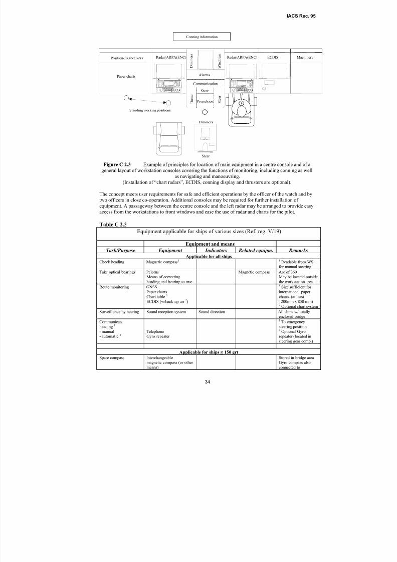
8/2/2019 Iacs Bridge Design,Equipmenr Arrangement and Procedure.
http://slidepdf.com/reader/full/iacs-bridge-designequipmenr-arrangement-and-procedure 34/80
IACS Rec. 95
34
Figure C 2.3 Example of principles for location of main equipment in a centre console and of a
general layout of workstation consoles covering the functions of monitoring, including conning as well
as navigating and manoeuvring.
(Installation of “chart radars”, ECDIS, conning display and thrusters are optional).
The concept meets user requirements for safe and efficient operations by the officer of the watch and by
two officers in close co-operation. Additional consoles may be required for further installation of
equipment. A passageway between the centre console and the left radar may be arranged to provide easyaccess from the workstations to front windows and ease the use of radar and charts for the pilot.
Table C 2.3
Equipment applicable for ships of various sizes (Ref. reg. V/19)
Equipment and means
Task/Purpose Equipment Indicators Related equipm. Remarks
Applicable for all ships
Check heading Magnetic compass1 1 Readable from WSfor manual steering
Take optical bearings Pelorus
Means of correctingheading and bearing to true
Magnetic compass Arc of 360˚
May be located outsidethe workstation area.
Route monitoring GNSSPaper chartsChart table 1
ECDIS (w/back-up arr 2)
1 Size sufficient for international paper charts. (at least
1200mm x 850 mm)2 Optional chart system
Surveillance by hearing Sound reception system Sound direction All ships w/ totallyenclosed bridge
Communicate
heading 1
- manual- automatic 2
TelephoneGyro repeater
1 To emergency
steering position2 Optional Gyrorepeater (located in
steering gear comp.)
Applicable for ships ≥ 150 grt
Spare compass Interchangeablemagnetic compass (or other
means)
Stored in bridge areaGyro compass also
connected to
Dimmers
Radar/ARPA(ENC) ECDIS MachineryRadar/ARPA(ENC)
Standing working positions
Communication
W i n d o w s
D i m m e r s
Propulsion T h r u s t
Steer
S t e e r
Steer
Alarms
Position-fix receivers
Paper charts
Conning information
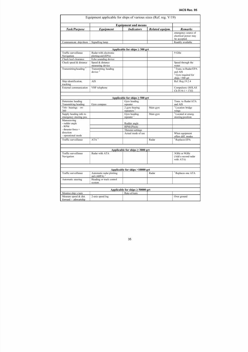
8/2/2019 Iacs Bridge Design,Equipmenr Arrangement and Procedure.
http://slidepdf.com/reader/full/iacs-bridge-designequipmenr-arrangement-and-procedure 35/80
IACS Rec. 95
35
Equipment applicable for ships of various sizes (Ref. reg. V/19)
Equipment and means
Task/Purpose Equipment Indicators Related equipm. Remarksemergency source of
electrical power may be accepted.
Communicate ship/shore Signalling lamp Readily available
Applicable for ships ≥ 300 grt Traffic surveillance
Navigation
Radar with electronic
plotting aid (EPA)
9 GHz
Check keel clearance Echo sounding device
Check speed & distance Speed & distancemeasuring device
Speed through thewater
Transmitting heading 1 Transmitting headingdevice 2
1 Trans. to Radar/EPAand AIS2 Gyro required for ships >500 grt
Ship identification,tracking
AIS Ref. Reg.19.2.4
External communication VHF telephone Compulsory (SOLASCh IV/4-1 + 17(f)
Applicable for ships ≥ 500 grt Determine headingTransmitting heading Gyro compass
Gyro headingrepeater
Trans. to Radar/ATAand AIS
Take bearings – arc
360˚
2 gyro bearing
repeaters 1Main gyro 1 Location bridge
wings
Supply heading info toemergency steering pos.
Gyro headingrepeater 1
Main gyro 1 Located at emerg.steering position
Rudder angle
RPM/(Pitch)
Thruster settings
Manoeuvring- rudder angle
- RPM
- thruster force +direction- operational mode
Actual mode of use When equipment
offers diff. modes
Traffic surveillance ATA 1 Radar 1 Replaces EPA
Applicable for ships ≥ 3000 grt
Traffic surveillance
Navigation
Radar with ATA 3GHz or 9GHz
(Add a second radar with ATA)
Applicable for ships >10000 grt
Traffic surveillance Automatic radar plottingaid (ARPA) 1 Radar
1
Replaces one ATA
Automatic steering Heading or track controlsystem
Applicable for ships ≥ 50000 grt
Monitor ship’s turn Rate-of-turn
Measure speed & dist.forward + athwartship
2-axis speed log Over ground
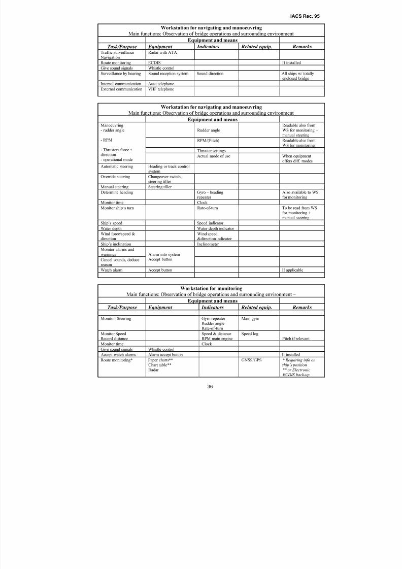
8/2/2019 Iacs Bridge Design,Equipmenr Arrangement and Procedure.
http://slidepdf.com/reader/full/iacs-bridge-designequipmenr-arrangement-and-procedure 36/80
IACS Rec. 95
36
Workstation for navigating and manoeuvring
Main functions: Observation of bridge operations and surrounding environment
Equipment and means
Task/Purpose Equipment Indicators Related equip. RemarksTraffic surveillance
Navigation
Radar with ATA
Route monitoring ECDIS If installed
Give sound signals Whistle controlSurveillance by hearing Sound reception system Sound direction All ships w/ totallyenclosed bridge
Internal communication Auto telephone
External communication VHF telephone
Workstation for navigating and manoeuvring
Main functions: Observation of bridge operations and surrounding environment
Equipment and means
Rudder angle
Readable also from
WS for monitoring +manual steering
RPM/(Pitch) Readable also fromWS for monitoring
Thruster settings
Manoeuvring
- rudder angle
- RPM
- Thrusters force +direction
- operational modeActual mode of use When equipment
offers diff. modes
Automatic steering Heading or track controlsystem
Override steering Changeover switch,steering tiller
Manual steering Steering tiller
Determine heading Gyro – heading
repeater
Also available to WS
for monitoring
Monitor time Clock
Monitor ship’s turn Rate-of-turn To be read from WS
for monitoring +manual steering
Ship’s speed Speed indicator
Water depth Water depth indicator
Wind force/speed &direction
Wind speed&direction indicator
Ship’s inclination Inclinometer
Monitor alarms and
warnings
Cancel sounds, deducereason
Alarm info systemAccept button
Watch alarm Accept button If applicable
Workstation for monitoring
Main functions: Observation of bridge operations and surrounding environment –
Equipment and means
Task/Purpose Equipment Indicators Related equip. Remarks
Monitor Steering Gyro repeater Rudder angle
Rate-of-turn
Main gyro
Monitor SpeedRecord distance
Speed & distanceRPM main engine
Speed logPitch if relevant
Monitor time Clock
Give sound signals Whistle control
Accept watch alarms Alarm accept button If installed
Route monitoring* Paper charts**Chart table**
Radar
GNSS/GPS * Requiring info on ship’s position
** or Electronic ECDIS back-up
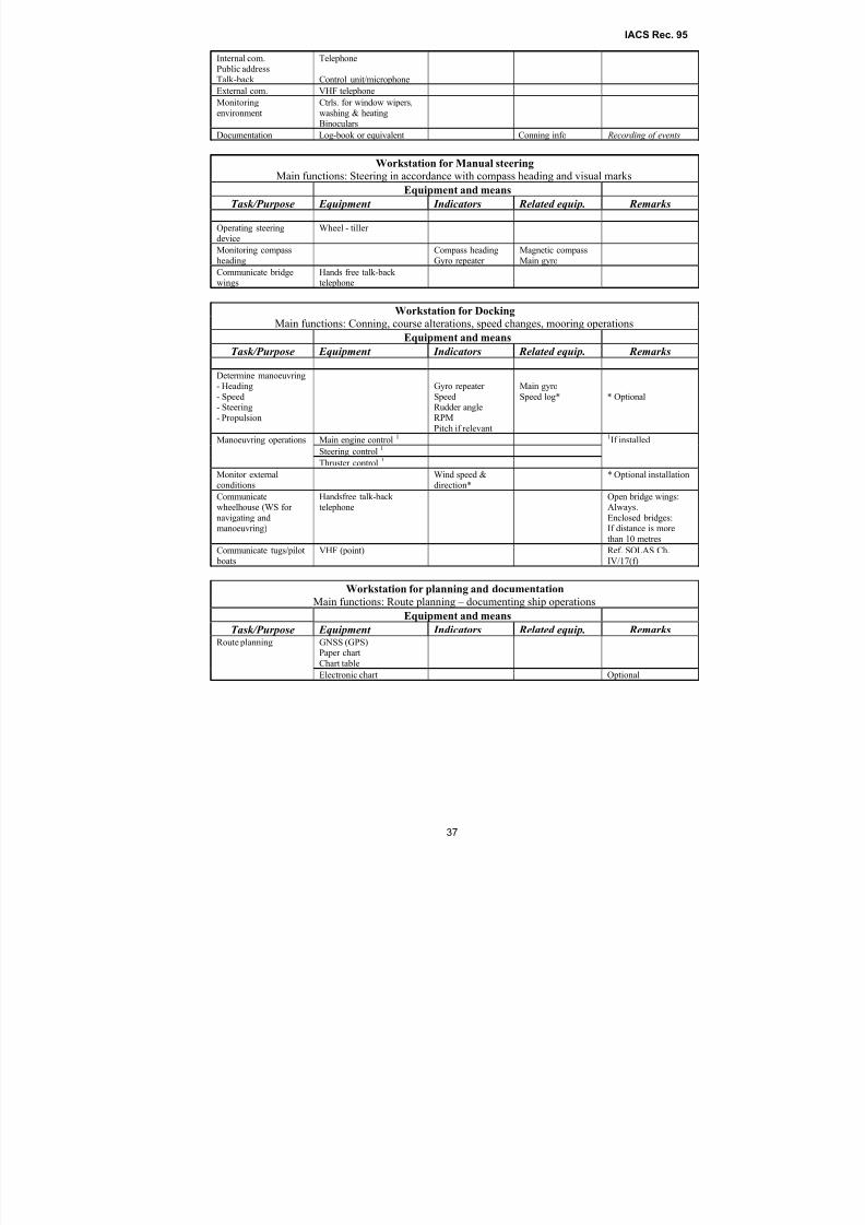
8/2/2019 Iacs Bridge Design,Equipmenr Arrangement and Procedure.
http://slidepdf.com/reader/full/iacs-bridge-designequipmenr-arrangement-and-procedure 37/80
IACS Rec. 95
37
Internal com.Public address
Talk-back
Telephone
Control unit/microphone
External com. VHF telephone
Monitoring
environment
Ctrls. for window wipers,
washing & heatingBinoculars
Documentation Log-book or equivalent Conning info Recording of events
Workstation for Manual steering
Main functions: Steering in accordance with compass heading and visual marks
Equipment and means
Task/Purpose Equipment Indicators Related equip. Remarks
Operating steeringdevice
Wheel - tiller
Monitoring compass
heading
Compass heading
Gyro repeater
Magnetic compass
Main gyro
Communicate bridgewings
Hands free talk-back telephone
Workstation for Docking
Main functions: Conning, course alterations, speed changes, mooring operations
Equipment and means
Task/Purpose Equipment Indicators Related equip. Remarks
Determine manoeuvring- Heading
- Speed- Steering
- Propulsion
Gyro repeater
SpeedRudder angleRPM
Pitch if relevant
Main gyro
Speed log* * Optional
Main engine control 1
Steering control1
Manoeuvring operations
Thruster control 1
1If installed
Monitor externalconditions
Wind speed &direction*
* Optional installation
Communicatewheelhouse (WS for
navigating andmanoeuvring)
Handsfree talk-back telephone
Open bridge wings:Always.
Enclosed bridges:If distance is more
than 10 metres
Communicate tugs/pilot
boats
VHF (point) Ref. SOLAS Ch.
IV/17(f)
Workstation for planning and documentation
Main functions: Route planning – documenting ship operationsEquipment and means
Task/Purpose Equipment Indicators Related equip. RemarksGNSS (GPS)Paper chart
Chart table
Route planning
Electronic chart Optional
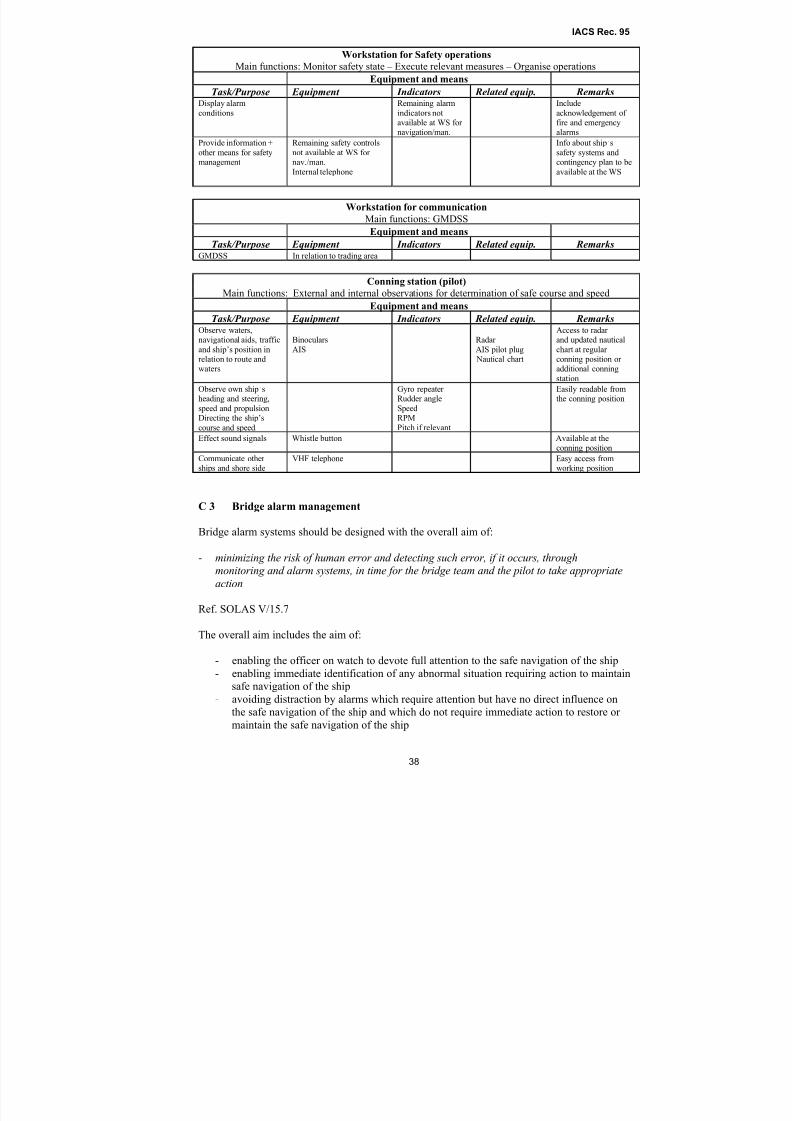
8/2/2019 Iacs Bridge Design,Equipmenr Arrangement and Procedure.
http://slidepdf.com/reader/full/iacs-bridge-designequipmenr-arrangement-and-procedure 38/80
IACS Rec. 95
38
Workstation for Safety operations
Main functions: Monitor safety state – Execute relevant measures – Organise operations
Equipment and means
Task/Purpose Equipment Indicators Related equip. RemarksDisplay alarm
conditions
Remaining alarm
indicators notavailable at WS for navigation/man.
Include
acknowledgement of fire and emergencyalarms
Provide information +
other means for safetymanagement
Remaining safety controls
not available at WS for nav./man.
Internal telephone
Info about ship’s
safety systems andcontingency plan to be
available at the WS
Workstation for communication
Main functions: GMDSS
Equipment and means
Task/Purpose Equipment Indicators Related equip. RemarksGMDSS In relation to trading area
Conning station (pilot)
Main functions: External and internal observations for determination of safe course and speed
Equipment and means
Task/Purpose Equipment Indicators Related equip. RemarksObserve waters,navigational aids, traffic
and ship’s position inrelation to route andwaters
Binoculars
AIS
Radar
AIS pilot plug Nautical chart
Access to radar and updated nautical
chart at regular conning position or additional conning
station
Observe own ship’sheading and steering,
speed and propulsion
Directing the ship’scourse and speed.
Gyro repeater Rudder angle
Speed
RPMPitch if relevant
Easily readable fromthe conning position
Effect sound signals Whistle button Available at theconning position
Communicate other ships and shore side
VHF telephone Easy access fromworking position
C 3 Bridge alarm management
Bridge alarm systems should be designed with the overall aim of:
- minimizing the risk of human error and detecting such error, if it occurs, throughmonitoring and alarm systems, in time for the bridge team and the pilot to take appropriate
action
Ref. SOLAS V/15.7
The overall aim includes the aim of:
- enabling the officer on watch to devote full attention to the safe navigation of the ship
- enabling immediate identification of any abnormal situation requiring action to maintain
safe navigation of the ship
- avoiding distraction by alarms which require attention but have no direct influence on
the safe navigation of the ship and which do not require immediate action to restore or
maintain the safe navigation of the ship
8/2/2019 Iacs Bridge Design,Equipmenr Arrangement and Procedure.
http://slidepdf.com/reader/full/iacs-bridge-designequipmenr-arrangement-and-procedure 39/80
IACS Rec. 95
39
Alarms and indicators on the navigating bridge should be minimized and only alarms and
indicators required by appropriate IMO Resolutions should be placed on the navigating bridge,
unless permitted by the flag administration. Ref. IMO Resolution A.830/3.16.
C 3.1 Alarm systems should be provided, indicating any fault requiring attention and should:
- activate an audible and visual alarm on the navigating bridge for any situation which
requires action by or attention of the officer of the watch;
- as far as practicable be designed on the self-monitoring principle.
C 3.2 Means of accepting all alarms on the bridge (both the source of alarm and alarms of
other equipment caused by the loss of sensor input) should be provided at the navigating and
manoeuvring workstation to avoid distraction. The system should enable immediate
identification of the alarm sources without requiring any operator action and enable immediate
silencing of the alarms by single operator action. See Guidance note, Annex A.
C 3.3 Acknowledgement of an alarm at either the instrument or an alarm panel should cancel
the audible warning at both sources and change the visual alarm from flashing to constant light.
C 3.4 Permanently inhibiting individual alarms should not be possible, but manual
suppression of local audible alarms may be accepted when this is clearly and constantly
indicated at the equipment and the unit is part of the alarm management system.
Note:
Local audible alarms may be manually suppressed by means of an on/off switch located on or close to
the equipment or by other means, e.g. electronically. The off-position should enable suppression of the
audible alarm when the equipment is part of a central alarm system and the on-position should engage
the local alarm when the equipment serves as a stand-alone unit.
C 3.5 If an alarm channel in a computer-based system is inhibited manually, then this should be clearly indicated by a visual signal.
C 3.6 Audible alarms should be maintained until they are accepted and the visual
identification of individual alarms should remain until the fault has been corrected.
Note:
Alarm volumes should be set sufficient to attract attention within the navigating bridge, but not to
distract or disorientate. Alarm tones may be different for indication of equipment/system failure,
operational warnings and alarms not related to safety of bridge operations respectively. (C 3.1)
C 3.7 Alarm indications should be red, or if on displays, red or otherwise highlighted. If alarmmessages are displayed on colour VDUs, the alarm status should remain visible in the event of
the failure of one colour of the display system. See Guidance, Annex A.
C 3.8 Alarm systems should be able to indicate more than one fault at the same time, and the
acknowledgement of any alarm should not inhibit another alarm, meaning that if an alarm has
been acknowledged and a second fault occurs before the first is rectified, the audible and visual
alarms are to operate again.
C 3.9 A new alarm condition should be clearly distinguishable from those existing and already
acknowledged showing a constant light, by indicating new alarms by a flashing light.
See Guidance, Annex A.
C 3.10 Provisions should be made for functional testing of required alarms and indicators.

8/2/2019 Iacs Bridge Design,Equipmenr Arrangement and Procedure.
http://slidepdf.com/reader/full/iacs-bridge-designequipmenr-arrangement-and-procedure 40/80
IACS Rec. 95
40
C 3.11 Alarm systems should be continuously powered and should have an automatic change-
over to stand-by power supply, like battery supply or other means, in case of loss of normal
power supply.
C 3.11 Failure of the normal or backup power supply of the alarm system should be indicated
by an alarm.
C 3.12 Loss of system communication should be indicated by an alarm.
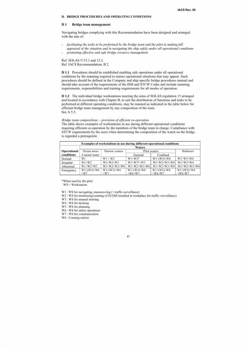
8/2/2019 Iacs Bridge Design,Equipmenr Arrangement and Procedure.
http://slidepdf.com/reader/full/iacs-bridge-designequipmenr-arrangement-and-procedure 41/80
IACS Rec. 95
41
D. BRIDGE PROCEDURES AND OPERATING CONDITIONS
D 1 Bridge team management
Navigating bridges complying with this Recommendation have been designed and arranged
with the aim of:
- facilitating the tasks to be performed by the bridge team and the pilot in making full
appraisal of the situation and in navigating the ship safely under all operational conditions- promoting effective and safe bridge resource management
Ref. SOLAS V/15.1 and 15.2.
Ref. IACS Recommendation, B 2.
D 1.1 Procedures should be established enabling safe operations under all operational
conditions by the manning required to master operational situations that may appear. Such
procedures should be defined in the Company and ship specific bridge procedures manual and
should take account of the requirements of the ISM and STCW Codes and include manningrequirements, responsibilities and training requirements for all modes of operation.
D 1.2 The individual bridge workstations meeting the aims of SOLAS regulation 15 arranged
and located in accordance with Chapter B, to suit the distribution of functions and tasks to be
performed at different operating conditions, may be manned as indicated in the table below for
efficient bridge team management by any composition of the team.
See A 5.5.
Bridge team compositions – provision of efficient co-operationThe table shows examples of workstations in use during different operational conditions
requiring efficient co-operation by the members of the bridge team in charge. Compliance withSTCW requirements by the users when determining the composition of the watch on the bridge
is regarded a prerequisite.
Examples of workstations in use during different operational conditions
Waters
Pilot watersOperational
conditionsOcean areas
Coastal water
Narrow waters
General Confined
Harbours
Normal W1 W1 + W2 W1+W2* W1+(W3)+W8 W1+W3+W4
Irregular W1+W2 W1+W2+W3 W1+W2*+W3 W1+W2+W3+W8 W1+W3+W4
Abnormal W1+W2+W3 W1+W2+W3+W8 W1+W2+W3+W8 W1+W2+W3+W8 W1+W2+W3+W4
Emergency W1+(W3)+W6+W7
W1+(W3)+W6+W7
W1+(W3)+W8+W6+W7
W1+(W3)+W8+W6+W7
W1+(W3)+W4+W6+W7
*When used by the pilot
WS = Workstation
W1 : WS for navigating, manoeuvring (+ traffic surveillance)
W2 : WS for monitoring/conning (if ECDIS installed at workplace for traffic surveillance)
W3 : WS for manual steering
W4 : WS for docking
W5 : WS for planning
W6 : WS for safety operations
W7 : WS for communicationW8 : Conning station
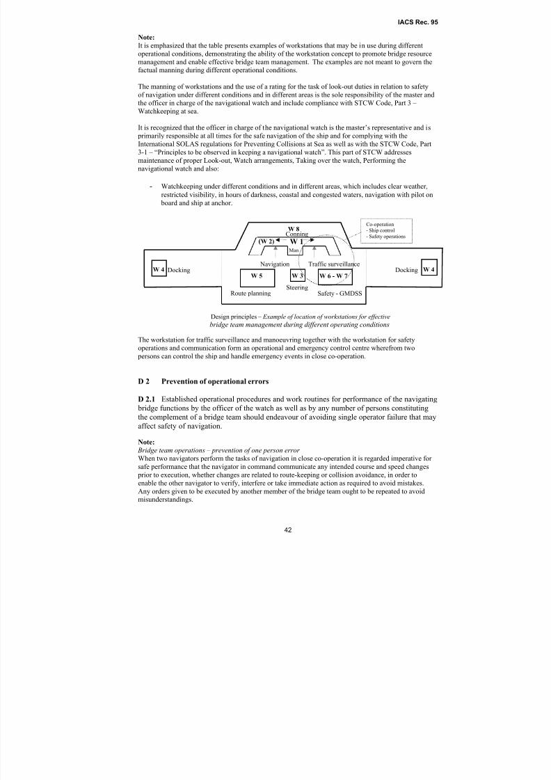
8/2/2019 Iacs Bridge Design,Equipmenr Arrangement and Procedure.
http://slidepdf.com/reader/full/iacs-bridge-designequipmenr-arrangement-and-procedure 42/80
IACS Rec. 95
42
Note:
It is emphasized that the table presents examples of workstations that may be in use during different
operational conditions, demonstrating the ability of the workstation concept to promote bridge resource
management and enable effective bridge team management. The examples are not meant to govern the
factual manning during different operational conditions.
The manning of workstations and the use of a rating for the task of look-out duties in relation to safety
of navigation under different conditions and in different areas is the sole responsibility of the master andthe officer in charge of the navigational watch and include compliance with STCW Code, Part 3 –
Watchkeeping at sea.
It is recognized that the officer in charge of the navigational watch is the master’s representative and is
primarily responsible at all times for the safe navigation of the ship and for complying with the
International SOLAS regulations for Preventing Collisions at Sea as well as with the STCW Code, Part
3-1 – “Principles to be observed in keeping a navigational watch”. This part of STCW addresses
maintenance of proper Look-out, Watch arrangements, Taking over the watch, Performing the
navigational watch and also:
- Watchkeeping under different conditions and in different areas, which includes clear weather,
restricted visibility, in hours of darkness, coastal and congested waters, navigation with pilot on board and ship at anchor.
The workstation for traffic surveillance and manoeuvring together with the workstation for safety
operations and communication form an operational and emergency control centre wherefrom two
persons can control the ship and handle emergency events in close co-operation.
D 2 Prevention of operational errors
D 2.1 Established operational procedures and work routines for performance of the navigating
bridge functions by the officer of the watch as well as by any number of persons constituting
the complement of a bridge team should endeavour of avoiding single operator failure that may
affect safety of navigation.
Note:
Bridge team operations – prevention of one person error
When two navigators perform the tasks of navigation in close co-operation it is regarded imperative for
safe performance that the navigator in command communicate any intended course and speed changes
prior to execution, whether changes are related to route-keeping or collision avoidance, in order to
enable the other navigator to verify, interfere or take immediate action as required to avoid mistakes.Any orders given to be executed by another member of the bridge team ought to be repeated to avoid
misunderstandings.
Traffic surveillance Navigation
SteeringRoute planning Safety - GMDSS
Docking Docking
Man
Design principles – Example of location of workstations for effective
bridge team management during different operating conditions
W 1
W 3W 4 W 4
W 5 W 6 - W 7
(W 2) ConningW 8
Co-operation
- Ship control
- Safety operations
8/2/2019 Iacs Bridge Design,Equipmenr Arrangement and Procedure.
http://slidepdf.com/reader/full/iacs-bridge-designequipmenr-arrangement-and-procedure 43/80
IACS Rec. 95
43
Navigating in accordance with the advice of the pilot
It is the responsibility of the captain of the ship that the route has been planned from the port of
departure to the port of destination. It is regarded imperative for safe navigation that the use of the
planned route is confirmed by the pilot or adjusted by the pilot and accepted by the captain prior to the
start of the pilotage. Alternatively, that the pilot’s planned route for the waters is accepted by the captain
and displayed for the use of navigating officers.
It is regarded imperative for avoidance of misunderstandings and to ensure correct task performance,that advice given by the pilot is repeated by the officer in command prior to execution and when
relevant, and also by the member of the bridge team assisting in executing orders.
D 3 Procedures related to SOLAS regulation 24, 25, 27 and 28
D 3.1 The following routines should be included and emphasized in the regular bridge
procedures:
- Use of heading and/or track control systems
- Testing of manual steering system after prolonged use of automatic steering system- Operation of steering gear
- Updating of nautical charts and nautical publications
- Recording of navigational activities
----------
Annex A Guidance and examples relating to requirements of the IACS
Recommendation for application of SOLAS V/15 for newbuildings
Guidance notes and examples as to how various requirements may be met by acceptable technical
solutions or other remedies are given in a separate document, Annex A to this IACS Recommendation. None of these guidance notes are mandatory in relation to the recommended requirements.
The guidance given does not exclude solutions that fulfil the purpose and intention of the functional
requirement providing other requirements and the overall bridge functionality are not adversely affected.
Appendix 1 of Annex A Tasks and related means – Examples of location of main equipment. The title
of the Annex indicates the content.
Annex B Facts and principles related to IACS Recommendation for application of
SOLAS V/15 for newbuildings
Annex B serves as the interpretation of the content of SOLAS regulation V/15 and intends to provide
information about the basis for the development of the Recommendation.
The annex summarizes certain facts that should assist in achieving a common understanding of SOLAS
regulation 15 and the framework of the Recommendation. The information given may also make
stakeholders more familiar with the approach and platform of the Recommendation based on the content
of SOLAS regulation 15 and clarify the reason why certain comments received cannot be regarded
applicable in the context of a Recommendation for application of SOLAS V/15 for newbuildings.
Appendix 1 of Annex B clarifies of the content of each aim specified in SOLAS regulation V/15.
The appendix clarifies the understanding of each aim and by defining the terms and expressions used
also indicates what compliance with the aims should entail.

8/2/2019 Iacs Bridge Design,Equipmenr Arrangement and Procedure.
http://slidepdf.com/reader/full/iacs-bridge-designequipmenr-arrangement-and-procedure 44/80
Annex A to IACS Rec. 95
ANNEX A
Guidance and examples relating to requirements of IACS Recommendation for application of regulation V/15

8/2/2019 Iacs Bridge Design,Equipmenr Arrangement and Procedure.
http://slidepdf.com/reader/full/iacs-bridge-designequipmenr-arrangement-and-procedure 45/80
Annex A to IACS Rec. 95
2
Introduction…………………………………………………………………………………… 3
B 2 Type and range of workstations………………………………………………………. 4
B 3 Working environment………………………………………………………………… 4
B 5 Workstation arrangements and required fields of vision……………………………... 4
B 6 Fields of vision and bridge window arrangement……………………………………. 5
B 7 Workstation layout, consoles and chair arrangement………………………………… 6
C Design and arrangement of navigational systems and equipment……………………. 8
C 3 Bridge alarm management……………………………………………………………. 10
Appendix 1 to Annex A………………………………………………………………………. 11
1 Table of tasks and related means for safe operations……………………………….. 12
2 Individual workplaces arranged for internal access………………………………… 15
3 Redundant workstations with ECDIS installations…………………………………. 15
4 Self-explanatory diagram for location of equipment……………………………….. 16

8/2/2019 Iacs Bridge Design,Equipmenr Arrangement and Procedure.
http://slidepdf.com/reader/full/iacs-bridge-designequipmenr-arrangement-and-procedure 46/80
Annex A to IACS Rec. 95
3
Introduction
Guidance notes and examples as to how various requirements may be met by acceptable technical
solutions or other remedies are given in this Annex to IACS Recommendation for application of
SOLAS regulation V/15. None of these guidance notes exclude alternative solutions that may
fulfil the purpose and intention of the requirement providing other requirements and the overallbridge functionality are not adversely affected.
The guidance given is related to specific requirements, but some are given to exemplify design
and arrangement principles. The guidance may be improved and extended based on experience
gained from the use of the Recommendation and organized feedback from owners, builders,
manufacturers and the users on board the ships.
8/2/2019 Iacs Bridge Design,Equipmenr Arrangement and Procedure.
http://slidepdf.com/reader/full/iacs-bridge-designequipmenr-arrangement-and-procedure 47/80
Annex A to IACS Rec. 95
4
B 2 Type and range of workstations
B 2.3 Guidance note:
The type of tasks to be performed at the individual workstation and the operating procedures
employed may conclude whether a workstation of category A should be of type a) or b).
Workstations of category A, type a) should not include tasks that may prevent the officer in
charge of primary bridge functions to leave a workstation for additional functions instantly at anytime during operations.
B 3 Working environment
B 3.3 Guidance note:
The sound level measured 1 m from the outlets of air distribution systems should not exceed 60
dB(A).
B 3.6 Guidance note:
Red light should be used for dark adaptation. Fluorescent light is not feasible.
B 3.8 Guidance note:
Deckhead areas above workstations should preferably have a dark colour of matt, anti-gloss type
minimizing light reflection. The colour of bridge bulkheads should have a calm and matt
appearance.
B 5 Workstation arrangements and required fields of vision
B 5.1 Guidance note:
The workstation for navigating and manoeuvring should be arranged to allow an assisting officerto carry out route monitoring, which may include manual plotting of the ship’s position, and
course adjustments when required, while the officer in charge concentrates on traffic situations
and adjustment of course and speed as required to follow the route and avoid danger of collision.
If a paper chart system, which includes chart table and means for position-fixing, is to be used for
route monitoring, the system should be located at the workstation for monitoring. If an electronic
chart system (ECDIS) meeting the chart carriage requirements in SOLAS regulations V/19.2.1.4
and 19.2.1.5 is to be used, the back-up arrangement should be located at the workstation for
monitoring. The back-up arrangement may be electronic means, paper charts or a combination of
both.
The workstation for monitoring, also incorporating the function of route monitoring, should be
considered part of a workstation for navigating and manoeuvring. The workplaces for route
monitoring and traffic surveillance should be adjacent to enable easy communication and
cooperation when two navigators operate the workstation as well as providing the single officer
of the watch with a workstation for safe and efficient performance of all the tasks when he is the
only navigator on the bridge and is to use both the working position for route
monitoring/position-fixing and the working position for traffic surveillance/manoeuvring.
B 5.3.1 Guidance note:
On a bridge with enclosed bridge wings it should be possible to obtain the view of 360˚ from
inside the bridge area by using two positions, one on each side of the workstation for navigatingand manoeuvring, not being more than 15 m apart. This guideline may also be applicable for
providing the required field of vision within the confines of wheelhouses with a total breath of
more than 18 metres.
8/2/2019 Iacs Bridge Design,Equipmenr Arrangement and Procedure.
http://slidepdf.com/reader/full/iacs-bridge-designequipmenr-arrangement-and-procedure 48/80
Annex A to IACS Rec. 95
5
B 5.4 Guidance note:
In general, it should be possible to achieve the view required forward of the bow from a sitting
eye height of 1400 mm. If this is found unreasonable due to constructional matters related to
carriage of cargo, a standing eye height as specified in B 6.3 may be accepted. See also B 7.8.
B 5.7 Guidance note:
The workstation for navigating and manoeuvring should be located on the starboard side close to
the centreline if practicable.
B 5.8.1 Guidance note:
Location of bulwarks and bulkheads in a line of sight seen from a seated working position at the
front workstations will help reducing the size of internal blind sector. A blind sector covering the
view abaft the beam on port side may be considered acceptable for workstations to be used
infrequently by the watch officer for short periods at a time (e.g. W.S. for communication).
B 6 Fields of vision and bridge window arrangement
B 6.2 Guidance note:
The height of the lower edge of windows above the floor surface should not exceed 1000 mm
within the required field of vision.
B 6.3 Guidance note:
The height of the upper edge should be at least 2000 mm. A vertical angle of view of not less
than 5˚ above a horizontal line from a standing eye height should be provided.
B 6.4 Guidance note:
The division between windowpanes within the required field of vision should not exceed 150mm. If stiffeners are used, divisions should not exceed 100 mm in width, if practicable, and 120
mm in depth. The width of windowpanes within the field of vision required for traffic
surveillance should not be less than 1200 mm in order to limit the number of stiffeners.
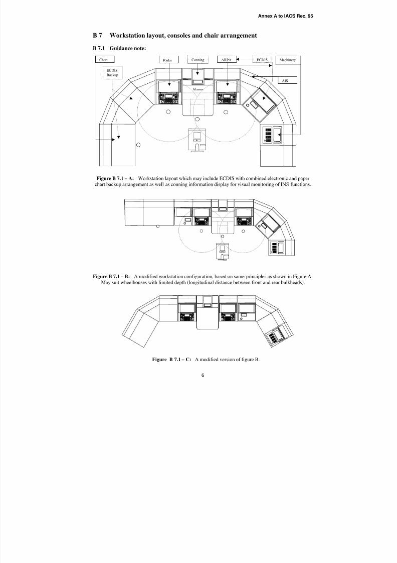
8/2/2019 Iacs Bridge Design,Equipmenr Arrangement and Procedure.
http://slidepdf.com/reader/full/iacs-bridge-designequipmenr-arrangement-and-procedure 49/80
Annex A to IACS Rec. 95
6
B 7 Workstation layout, consoles and chair arrangement
B 7.1 Guidance note:
Figure B 7.1 – A: Workstation layout which may include ECDIS with combined electronic and paper
chart backup arrangement as well as conning information display for visual monitoring of INS functions.
Figure B 7.1 – B: A modified workstation configuration, based on same principles as shown in Figure A.May suit wheelhouses with limited depth (longitudinal distance between front and rear bulkheads).
Figure B 7.1 – C: A modified version of figure B.
Alarms
ECDIS MachineryARPARadar Chart
ECDISBackup
Conning
AIS
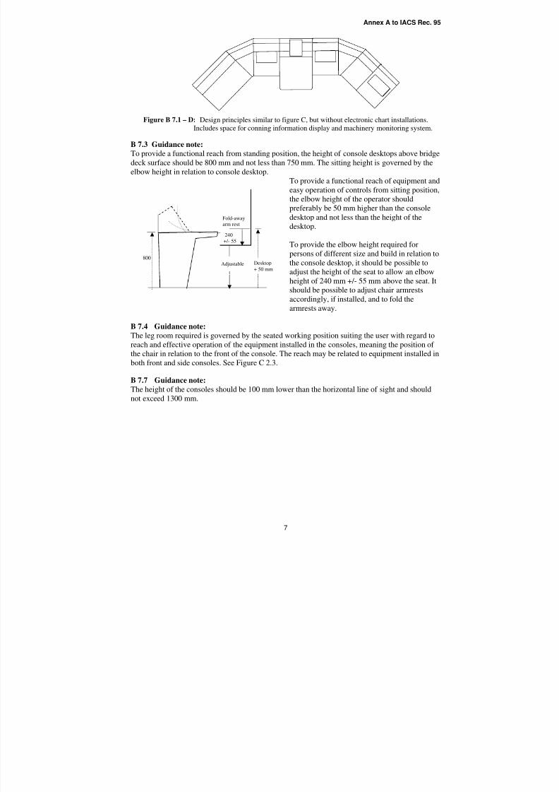
8/2/2019 Iacs Bridge Design,Equipmenr Arrangement and Procedure.
http://slidepdf.com/reader/full/iacs-bridge-designequipmenr-arrangement-and-procedure 50/80
Annex A to IACS Rec. 95
7
Figure B 7.1 – D: Design principles similar to figure C, but without electronic chart installations.
Includes space for conning information display and machinery monitoring system.
B 7.3 Guidance note:
To provide a functional reach from standing position, the height of console desktops above bridge
deck surface should be 800 mm and not less than 750 mm. The sitting height is governed by the
elbow height in relation to console desktop.
To provide a functional reach of equipment and
easy operation of controls from sitting position,
the elbow height of the operator should
preferably be 50 mm higher than the console
desktop and not less than the height of the
desktop.
To provide the elbow height required for
persons of different size and build in relation to
the console desktop, it should be possible to
adjust the height of the seat to allow an elbow
height of 240 mm +/- 55 mm above the seat. It
should be possible to adjust chair armrestsaccordingly, if installed, and to fold the
armrests away.
B 7.4 Guidance note:
The leg room required is governed by the seated working position suiting the user with regard to
reach and effective operation of the equipment installed in the consoles, meaning the position of
the chair in relation to the front of the console. The reach may be related to equipment installed in
both front and side consoles. See Figure C 2.3.
B 7.7 Guidance note:
The height of the consoles should be 100 mm lower than the horizontal line of sight and shouldnot exceed 1300 mm.
800Desktop
+ 50 mm
240
+/- 55
Adjustable
Fold-away
arm rest
8/2/2019 Iacs Bridge Design,Equipmenr Arrangement and Procedure.
http://slidepdf.com/reader/full/iacs-bridge-designequipmenr-arrangement-and-procedure 51/80
Annex A to IACS Rec. 95
8
C. Design and arrangement of navigational systems and equipment
Guidance note:
Principles for selection and arrangement of navigational systems and equipment in accordance
with applicable aims of SOLAS V/15.
Particularly important topics include, but are not restricted to, the following:
a. The design and arrangement of equipment on the bridge, particularly the display of user
inputs and commands, should help to prevent single person error by facilitating
monitoring and cross checks between members of the bridge team and pilot.
b. The design and arrangement of equipment on the bridge should facilitate validation of
electronic information by actual observation of the surrounding environment and the use
of any means available.
c. The design and arrangement of equipment on the bridge should provide convenient and
continuous access to essential information for both the bridge team and pilot.
d. The current operating modes should at all times be clearly indicated to the bridge team
and pilot. Indications of failure modes should be presented in a clear and unambiguousmanner to enable the bridge team and pilot to understand the nature of the failure and its
consequences.
e. Information (including control status) should be presented consistently within and
between different sub-systems and items of equipment. Standardized symbols and coding
should be used.
f. The functionality and automation to be provided should take account of the likely
workload of the bridge team and pilot. This would typically influence selection of items
including but not restricted to form of AIS implementation, ECDIS, autopilot
functionality, bridge wing consoles, radar capability, alarm systems, dimmers.
g. Confirmation that the bridge design, equipment selection and arrangement, and the
procedures meet the aims of SOLAS V/15 should be sought from representative users.
C 1.1 Note:
IEC general test standard for navigational systems and equipment
It should be noted that the current edition of the General test requirements, IEC 60945 ed.4, 2002,
extends the detail of operational tests particularly for equipment which is operated through
software menus. The layout of the Clause on minimum performance requirements has been
changed to give a better grouping of ergonomics, hardware and software requirements. The EMC
tests have been revised with the frequency range having been extended from 1 GHz to 2 GHz.
A comparison of the test requirements in the third and fourth editions is given in annex G of IEC
60945 to assist manufacturers and test houses in the use of the new edition, and may be
informative to ship owners. The fourth edition cancels and replaces the third edition published in
1996 and constitutes a technical revision.
C 2.1.3 Note:
In order to meet relevant aims of Regulation 15, all ships should carry ECDIS with electronic
back-up arrangement, provided ENC (electronic nautical charts) are available. The use of ECDIS
enhances the safety and efficiency of route planning and monitoring thereby minimizing the
danger of grounding, reducing workloads and increasing the quality of traffic surveillance.
Because the carriage of electronic chart system is optional in regulation 19, it is left to the flag
Administration to decide if the carriage should be regarded mandatory for their ships.
8/2/2019 Iacs Bridge Design,Equipmenr Arrangement and Procedure.
http://slidepdf.com/reader/full/iacs-bridge-designequipmenr-arrangement-and-procedure 52/80
Annex A to IACS Rec. 95
9
When using chart systems with automatic positioning of the ship in the chart, it is regarded
imperative for safety of navigation that the navigation procedures and work routines specify the
importance of controlling the ship’s position by other independent means.
Introduction of new technology for the purpose of enhancing safety of navigation
The requirement for a ship to carry charts is contained in Regulation 19, supported by
Regulations 2, 9 and 27. Regulation 19 states that the chart carriage requirement may be met by
the use of an Electronic Chart and Display and Information System (ECDIS) supported by back-
up arrangement. In this respect, there are some key items to be aware of when a ship is to satisfy
the chart carriage requirement by electronic means:
1) ECDIS equipment, specified in Resolutions A.817 (19), MSC 64 (67) and MSC 86 (70),
must be type approved.
2) Charts to be used are Electronic Navigational Charts (ENC), which conform to standards
defined by the International Hydrographic Organization (IHO).
3) The ECDIS Performance Standard permits ECDIS to operate optionally in the RasterChart Display System (RCDS) mode of operation using Raster Navigational Charts (RNC). The
RCDS mode of operation is only to be used for those areas where ENCs have not been published
on the condition that the ECDIS is “used together with an appropriate folio of up-to-date paper
charts”.
4) ENC are superior to RNC and therefore of vital importance to safe navigation, especially
in critical and complex waters. (See SN/Circ.207) However, individual Maritime States (to be
identified) may accept the use of RNC for the purposes of Safety of Navigation within less
complex waters under their jurisdiction for the time being until ENCs are available.
5) The ECDIS Performance Standard specifies the requirements for back-uparrangements but does not indicate which solutions may meet those requirements.
Regulation 19 states that an “appropriate folio of paper charts” may be used.
6) The requirements for ECDIS back-up arrangements state that adequate independent
back-up arrangements shall include facilities enabling a safe take-over of the ECDIS
functions in order to ensure that an ECDIS failure does not result in a cri tical situation. In
order to meet this requirement when paper charts are used for the purpose of ECDIS back-
up arrangement, the following should be included in the navigation procedures and work
routines:
- The planned route is to be inserted in the paper chart and the ship’s position needs be
updated regularly as required to enable an instant take-over of ECDIS functions,allowing a safe continuation of the navigation.
C 2.3 Guidance note:
In this workplace configuration (see Figure 2.3), a long centre console separating the front
workstations (see Appendix 1, Annex A) may be accepted if the official chart system in use is an
ECDIS installed at the workstation for navigating and manoeuvring (starboard), providing
propulsion and manual steering (tiller) are within reach from the working position at the port
workstation with backup chart system.
8/2/2019 Iacs Bridge Design,Equipmenr Arrangement and Procedure.
http://slidepdf.com/reader/full/iacs-bridge-designequipmenr-arrangement-and-procedure 53/80
Annex A to IACS Rec. 95
10
C 3 Bridge alarm management
C 3.2 Guidance note:
A bridge management system should separate alarms that affect safety of navigation and alarms
that do not influence safety of navigation in two groups.
The group of alarms related to safety of navigation should incorporate all system alarms,equipment alarms and operational warnings that are critical to safety of navigation, including the
detection of:
- operator disability (if detection system is installed)
- danger of collision
- heading deviations
- deviations from the route
- danger of grounding
- propulsion failure
- steering gear failure
Essential equipment and systems to be incorporated in such an alarm system should include:
- bridge navigational watch alarm system - BNWAS (if installed)
- heading information system
- heading / track control system
- position-fixing systems
- electronic chart system, if installed
- radar with electronic target plotting functions
- relevant machinery alarms for early warning
All groups of bridge alarms and warnings should preferably be centralised in a common panel orscreen at the workstation for navigation and manoeuvring.
C 3.6 Guidance note:
The following method of indication should be applied:
1) Active alarm status:
Red, blinking and audible
2) Active alarm status acknowledged:
Red, static (cancelling the audible alarm)
3) Active warning message - not critical:
Yellow, static (may be accompanied by a short audible attention signal)4) Normal condition:
No light (indication of a safe situation)
C 3.9 Guidance note:
In colour graphic systems, colours should not be used as the only means to distinguish between
the status of alarms and warnings.
8/2/2019 Iacs Bridge Design,Equipmenr Arrangement and Procedure.
http://slidepdf.com/reader/full/iacs-bridge-designequipmenr-arrangement-and-procedure 54/80
Annex A to IACS Rec. 95
11
Appendix 1 to Annex A
TASKS AND RELATED MEANS
EXAMPLES OF LOCATION OF MAIN EQUIPMENT
at workstations to be used by
the officer in charge of the navigational watchand
by two officers in close co-operation
List of content
1 Table of tasks and related means for safe operations…………………………………..... 12
2 Individual workplaces arranged for internal access…………………………………....... 15
3 Redundant workstations with ECDIS installations…………………………………........ 15
4 Self-explanatory diagram for location of equipment…………………………………..... 16
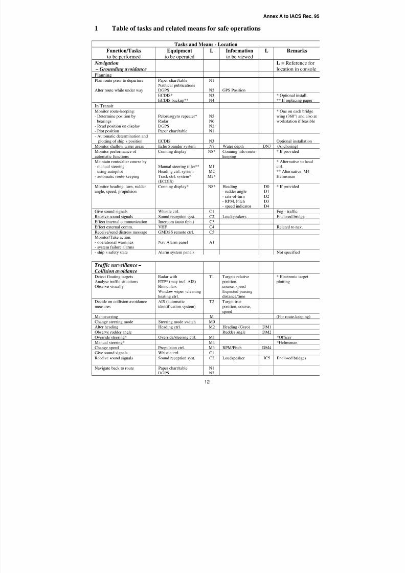
8/2/2019 Iacs Bridge Design,Equipmenr Arrangement and Procedure.
http://slidepdf.com/reader/full/iacs-bridge-designequipmenr-arrangement-and-procedure 55/80
Annex A to IACS Rec. 95
12
1 Table of tasks and related means for safe operations
Tasks and Means - Location
Function/Tasks
to be performed
Equipment
to be operated
L Information
to be viewed
L Remarks
Navigation
– Grounding avoidance
L = Reference for
location in consolePlanningPaper chart/table
Nautical publications
DGPS
N1
N2 GPS Position
Plan route prior to departure
Alter route while under way
ECDIS*
ECDIS backup**
N3
N4
* Optional install.
** If replacing paper
In TransitMonitor route-keeping:
- Determine position by
bearings
- Read position on display
- Plot position
Pelorus/gyro repeater*
Radar
DGPS
Paper chart/table
N5
N6
N2
N1
* One on each bridge
wing (360°) and also at
workstation if feasible
- Automatic determination and
plotting of ship’s position ECDIS N3 Optional installationMonitor shallow water areas Echo Sounder system N7 Water depth DN7 (Anchoring)
Monitor performance of
automatic functions
Conning display N8* Conning info route-
keeping
* If provided
Maintain route/alter course by
- manual steering
- using autopilot
- automatic route-keeping
Manual steering tiller**
Heading ctrl. system
Track ctrl. system*
(ECDIS)
M1
M2
M2*
* Alternative to head
ctrl.
** Alternative: M4 -
Helmsman
Monitor heading, turn, rudder
angle, speed, propulsion
Conning display* N8* Heading
- rudder angle
- rate-of-turn
- RPM, Pitch
- speed indicator
D0
D1
D2
D3
D4
* If provided
Give sound signals Whistle ctrl. C1 Fog - trafficReceive sound signals Sound reception syst. C2 Loudspeakers Enclosed bridge
Effect internal communication Intercom (auto tlph.) C3
Effect external comm. VHF C4 Related to nav.
Receive/send distress message GMDSS remote ctrl. C5
Monitor/Take action:
- operational warnings
- system failure alarms
Nav Alarm panel A1
- ship’s safety state Alarm system panels Not specified
Traffic surveillance –
Collision avoidanceDetect floating targets
Analyse traffic situationsObserve visually
Radar with
ETP* (may incl. AIS)Binoculars
Window wiper -cleaning
heating ctrl.
T1 Targets relative
position,course, speed
Expected passing
distance/time
* Electronic target
plotting
Decide on collision avoidance
measures
AIS (automatic
identification system)
T2 Target true
position, course,
speed
Manoeuvring M (For route-keeping)
Change steering mode Steering mode switch M0
Alter heading Heading ctrl. M2 Heading (Gyro) DM1
Observe rudder angle Rudder angle DM2
Override steering* Override/steering ctrl. M1 *Officer
Manual steering* M4 *Helmsman
Change speed Propulsion ctrl. M3 RPM/Pitch DM4
Give sound signals Whistle ctrl. C1Receive sound signals Sound reception syst. C2 Loudspeaker IC5 Enclosed bridges
Navigate back to route Paper chart/table
DGPS
N1
N2
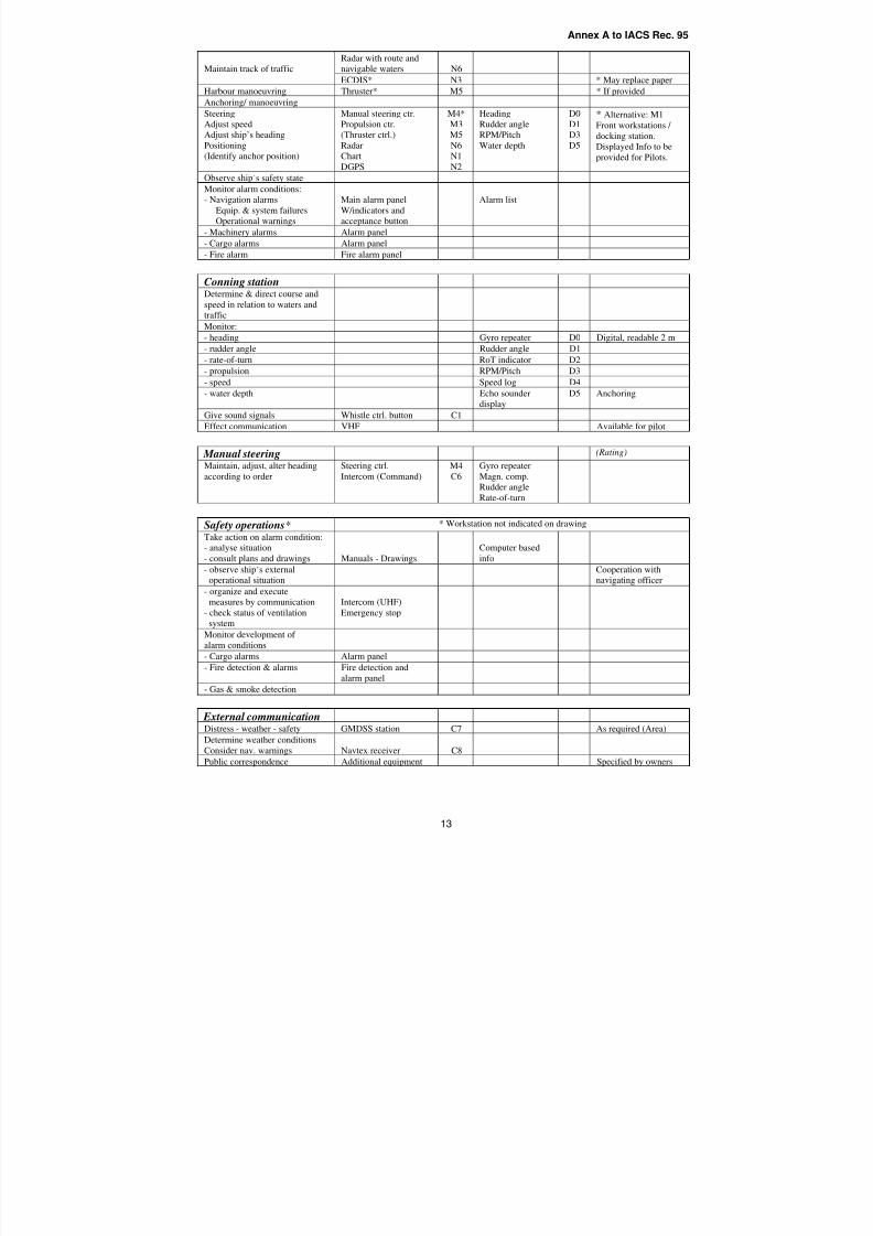
8/2/2019 Iacs Bridge Design,Equipmenr Arrangement and Procedure.
http://slidepdf.com/reader/full/iacs-bridge-designequipmenr-arrangement-and-procedure 56/80
Annex A to IACS Rec. 95
13
Radar with route and
navigable waters N6Maintain track of traffic
ECDIS* N3 * May replace paper
Harbour manoeuvring Thruster* M5 * If provided
Anchoring/ manoeuvring
Steering
Adjust speed
Adjust ship’s heading
Positioning
(Identify anchor position)
Manual steering ctr.
Propulsion ctr.
(Thruster ctrl.)
Radar
Chart
DGPS
M4*
M3
M5
N6
N1
N2
Heading
Rudder angle
RPM/Pitch
Water depth
D0
D1
D3
D5
* Alternative: M1
Front workstations /
docking station.
Displayed Info to be
provided for Pilots.
Observe ship’s safety state
Monitor alarm conditions:
- Navigation alarms
Equip. & system failures
Operational warnings
Main alarm panel
W/indicators and
acceptance button
Alarm list
- Machinery alarms Alarm panel
- Cargo alarms Alarm panel
- Fire alarm Fire alarm panel
Conning stationDetermine & direct course and
speed in relation to waters andtraffic
Monitor:
- heading Gyro repeater D0 Digital, readable 2 m
- rudder angle Rudder angle D1
- rate-of-turn RoT indicator D2
- propulsion RPM/Pitch D3
- speed Speed log D4
- water depth Echo sounder
display
D5 Anchoring
Give sound signals Whistle ctrl. button C1
Effect communication VHF Available for pilot
Manual steering(Rating)
Maintain, adjust, alter heading
according to order
Steering ctrl.
Intercom (Command)
M4
C6
Gyro repeater
Magn. comp.
Rudder angle
Rate-of-turn
Safety operations* * Workstation not indicated on drawing
Take action on alarm condition:
- analyse situation
- consult plans and drawings Manuals - Drawings
Computer based
info
- observe ship’s external
operational situation
Cooperation with
navigating officer
- organize and execute
measures by communication
- check status of ventilationsystem
Intercom (UHF)
Emergency stop
Monitor development of
alarm conditions
- Cargo alarms Alarm panel
- Fire detection & alarms Fire detection and
alarm panel
- Gas & smoke detection
External communicationDistress - weather - safety GMDSS station C7 As required (Area)
Determine weather conditions
Consider nav. warnings Navtex receiver C8
Public correspondence Additional equipment Specified by owners
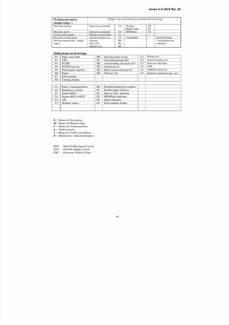
8/2/2019 Iacs Bridge Design,Equipmenr Arrangement and Procedure.
http://slidepdf.com/reader/full/iacs-bridge-designequipmenr-arrangement-and-procedure 57/80
Annex A to IACS Rec. 95
14
Docking operations
(bridge wings* )
* Bridge wing workstations are not indicated on drawing
Directing steering Intercom (command) C6 Heading
Rudder angle
D0
D1
Directing speed Intercom (command) C6 RPM/Pitch D3
Giving sound signals Whistle control button C1
Receiving sound signals Sound reception syst, C2 Loudspeaker Enclosed bridge
Perform manoeuvring – bridgewings*
SteeringProp. ctrls
Thruster ctrl.
M4M3
M5
* Installations notmandatory
Indications on drawingsN1 Paper chart table M0 Steering mode switch C1 Whistle ctrl.
N2 GPS M1 Override/steering tiller C2 Sound reception syst.
N3 ECDIS M2 Auto heading ctrl./track ctrl.* C3 Intercom (auto tlph.)
N4 ECDIS back-up M3 Propulsion ctr. C4 VHF
N5 Pelorus/gyro repeater M4 Main manual steering ctrl. C5 GMDSS remote ctrl.
N6 Radar M5 Thruster ctrl C6 Internal command com. syst.
N7 Echo sounder
N8 Conning display
A1 Panel –warnings/alarms D0 Heading display/gyro repater
A2 Machinery systems D1 Rudder angle indicator
T1 Radar/ARPA D2 Rate-of-Turn indicator
T1+ Radar/ARPA w/ENC D3 RPM/Pitch indicator
T2 AIS D4 Speed indicator
T3 Window wipers D5 Echo sounder display
N : Means for NavigationM: Means for Manoeuvring
C : Means for Communication
A : Alarm systems
T : Means for Traffic surveillance
D : Information - indicators/displays
HSV: SOLAS High Speed Vessels
OSV: Offshore Supply Vessels
ENC: Electronic Nautical Chart
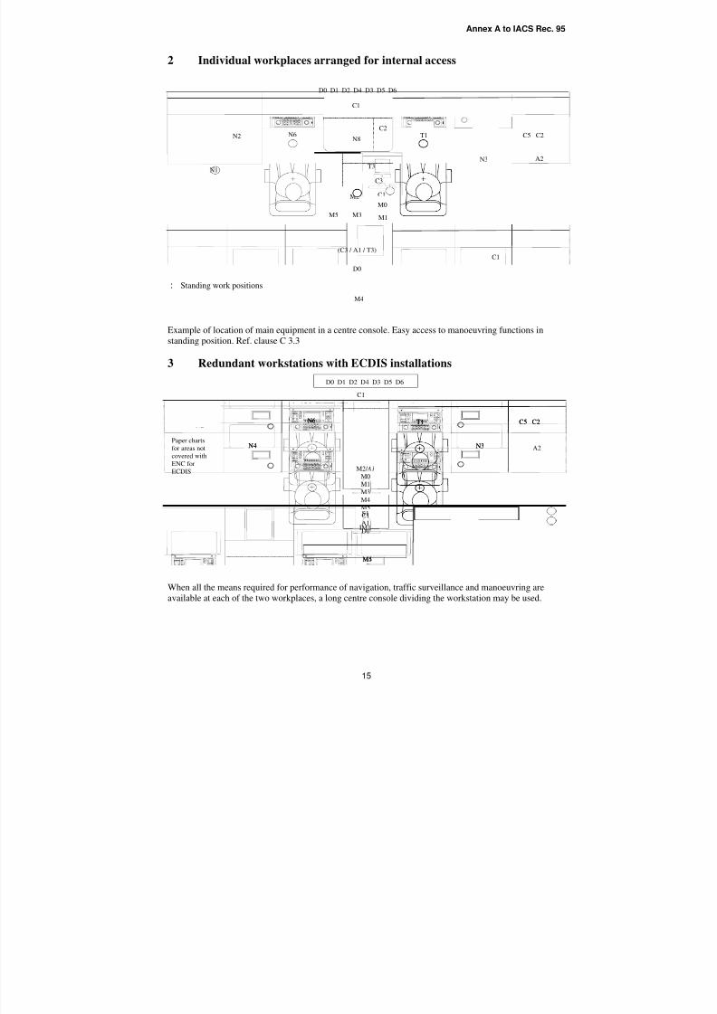
8/2/2019 Iacs Bridge Design,Equipmenr Arrangement and Procedure.
http://slidepdf.com/reader/full/iacs-bridge-designequipmenr-arrangement-and-procedure 58/80
Annex A to IACS Rec. 95
15
2 Individual workplaces arranged for internal access
: Standing work positions
Example of location of main equipment in a centre console. Easy access to manoeuvring functions in
standing position. Ref. clause C 3.3
3 Redundant workstations with ECDIS installations
When all the means required for performance of navigation, traffic surveillance and manoeuvring are
available at each of the two workplaces, a long centre console dividing the workstation may be used.
D0 D1 D2 D4 D3 D5 D6
C1
A1
T3 A3
A3
C2
Alarms
N8
M2
M0
M2
M1
M3M5
C1
A1
D0
M4
T1 C5 C2
N3
N6
N4
N2
D0 D1 D2 D4 D3 D5 D6
S1
A3
C2
Alarms
N8
M2/ A1
M0
M1
M3
M4
IM1
M5
T1 C5 C2
N3
S1
N6
N4
A2
A2Paper charts
for areas not
covered with
ENC for
ECDIS
C1
(C3 / A1 / T3)
C1 A1 T3
N7 N2
Alarms
M4
D0
C1
M5
M0
A3N8
C5 C2
C3 C4 C3
C2
M2
M1
T1
N1
N6
N3
M3
D0 D1 D2 D4 D3 D5 D6
C1
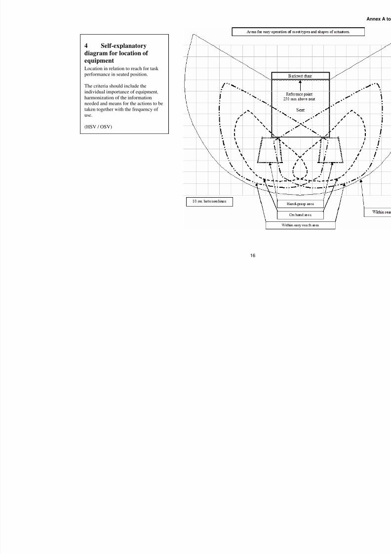
8/2/2019 Iacs Bridge Design,Equipmenr Arrangement and Procedure.
http://slidepdf.com/reader/full/iacs-bridge-designequipmenr-arrangement-and-procedure 59/80
16
4 Self-explanatory
diagram for location of
equipment
Location in relation to reach for task performance in seated position.
The criteria should include the
individual importance of equipment,
harmonization of the information
needed and means for the actions to be
taken together with the frequency of
use.
(HSV / OSV)

8/2/2019 Iacs Bridge Design,Equipmenr Arrangement and Procedure.
http://slidepdf.com/reader/full/iacs-bridge-designequipmenr-arrangement-and-procedure 60/80
Annex B to IACS Rec. 95
ANNEX B
SOLAS Regulation V/15
Facts and principles related to the IACS Recommendation
8/2/2019 Iacs Bridge Design,Equipmenr Arrangement and Procedure.
http://slidepdf.com/reader/full/iacs-bridge-designequipmenr-arrangement-and-procedure 61/80
Annex B to IACS Rec. 95
2
Facts and Principles Related To IACS Recommendation For Application Of SOLAS Regulation V/15 ForNewbuildings…………………………………………………………………………………………………........... 3
1 HOW TO COMPLY IN RESPONSE TO THE PRINCIPLES AND AIMS OF SOLAS
REGULATION V/15………………………………………………………………………………………. 3
1.1 SOLAS regulation V/15 and the complexity of interpretation………………………………………... 3
1.2 IMO considerations………………………………………………………………………………………. 4
2 THE CONCERN OF THE RECOMMENDATION AND THE APPROACH…………………………. 4
2.1 Decisions to be made and aims to be met by individual regulations……………………………….. 5
3 FACTS AND PRINCIPLES GOVERNING DECISIONS AND SOLUTIONS……………………….. 7
3.1 Bridge watch resources and design principles………………………………………......................... 7
3.1.1 Number of certified navigators on board – Bridge watch duty intervals……………………………. 7
3.1.2 Manning of the bridge – Design criteria………………………………………................................... 7
3.1.3 Manning of the bridge for safe navigation – Responsibility of the bridge management………….. 83.1.4 Bridge design criteria – Overall requirements……………………………………….......................... 8
3.2 User-oriented regulations……………………………………………………………………………….. 8
3.3 Bridge functions…………………………………………………………………………………………... 8
3.3.1 Task performance………………………………………………………………………………………… 9
3.4 The workstation concept…………………………………………………………………………………. 9
3.4.1 The workstation concept to be used on all regulation 15 bridges…………………………………… 9
3.5 Responsibility of providing workplaces for safe and efficient operations…………………………… 9
3.6 Competence, procedures and BRM - Responsibility of the management………………………... 9
3.7 Use of type approved equipment - Responsibility of the user……………………………………….. 103.7.1 Selection of system configurations and equipment for installation………………………………….. 10
3.7.2 The authority of IACS on behalf of flag state Administrations……………………………………….. 10
3.8 Responsibility of verification – Unified and predictable approval procedures……………………… 11
3.9 Compliance at the time of delivery of the ship - Responsibility of the shipbuilder………………… 11
4 CONCLUSIVE NOTE………………………………………..………..………..………..………..…….. 11
4.1 Bridge team qualifications, training and operational procedures……………………………………. 12
Appendix 1 to Annex B - Clarification of the Content of Each Aim…………………………………………….. 14
The Aims of SOLAS Regulation V/15………………………………………..………………………………. 15
AIM 15.1………………………………………..………………………………………..……………………… 15
AIM 15.2………………………………………..………………………………………..……………………… 17
AIM 15.3………………………………………..………………………………………..……………………… 17
AIM 15.4………………………………………..………………………………………..……………………… 18
AIM 15.5………………………………………..………………………………………..……………………… 19
AIM 15.6………………………………………..………………………………………..……………………… 20
AIM 15.7………………………………………..………………………………………..……………………… 20
8/2/2019 Iacs Bridge Design,Equipmenr Arrangement and Procedure.
http://slidepdf.com/reader/full/iacs-bridge-designequipmenr-arrangement-and-procedure 62/80
Annex B to IACS Rec. 95
3
SOLAS Regulation V/15
FACTS AND PRINCIPLES RELATED TO IACS RECOMMENDATION FOR
APPLICATION OF SOLAS REGULATION V/15 FOR NEWBUILDINGS
This document intends to provide information about the basis for the development of the
Recommendation and summarizes certain facts that should assist in achieving a common
understanding of regulation 15 and the framework of the Recommendation. The information givenmay also make stakeholders more familiar with the approach and platform of the Recommendation
based on the content of regulation 15 and clarify the reason why certain comments received cannot
be regarded applicable in the context of this Recommendation.
1. HOW TO COMPLY IN RESPONSE TO THE PRINCIPLES AND AIMS OF SOLAS
REGULATION V/15
Application of regulation 15 already in force will improve working conditions for the users
responsible for the safe and efficient performance of navigation functions, thus reducing operational
failures. A common implementation of the regulation has however proved difficult due to the lack of a suitable instrument for verifying compliance with the regulation.
The IACS Recommendation has been developed to serve as a common reference for verification of compliance with regulation V/15 at the time of delivery of the newbuilding. The Recommendation is
to be used for verification of compliance with regulation 15 and related regulations.
The use of the Recommendation implies that requirements of the SOLAS regulations V/19, 22, 24,25, 27 and 28 will be met with due regard to applicable aims of regulation 15 for the benefit of the
users. Furthermore, the use of the Recommendation should ascertain that shipbuilders and owners
can expect a unified, consistent and predictable approval process.
The Recommendation relates to the IMO’s regulatory regime of verifying compliance withregulations by documentation, survey and testing required to enable flag state Administrations to
issue the certificates as required for legally allowing the ship to be put in service.
It is assumed that relevant IMO survey schemes are reviewed as required to ascertain that the
regulation V/15 level of functionality and quality of the bridge system documented at the delivery of
the ship will be maintained throughout the lifetime of the ship.
1.1 Regulation V/15 and the complexity of interpretation
Regulation V/15 requires consideration of 7 specific aims when decisions are made for applying the
requirements of 6 individual regulations within 4 specific areas affecting the navigation bridge
system and safety of navigation. Furthermore, the Recommendation should serve as a reference for
verification of compliance with the complete regulation, as required at the delivery of newbuildingsof all sizes, including types of ships that may be navigated at service speeds up to 30 knots.
The complexity indicates that for the purpose of serving as platform for the requirements of theRecommendation, the interpretation part needs to focus on the content of SOLAS regulation V/15
and the regulatory framework of the Recommendation, as well as what compliance with the aims
may entail.
8/2/2019 Iacs Bridge Design,Equipmenr Arrangement and Procedure.
http://slidepdf.com/reader/full/iacs-bridge-designequipmenr-arrangement-and-procedure 63/80
Annex B to IACS Rec. 95
4
A common understanding of SOLAS regulation V/15 and its effect on regulations to be complied
with prior to the ship being put in service is regarded essential for a common acceptance of theRecommendation and a successful implementation of the regulation. Some of the comments on the
draft Recommendation revealed that there exists deviating understanding of the content of regulation15 and what compliance with the regulation should entail.
Any dispute on the interpretation of SOLAS regulation V/15 or requirements of the
Recommendation should point to deviating understanding of the relevant part(s) of the content of this
Annex, clarifying the consequences for appropriate compliance with the regulations of concern prior
to delivery of the ship and the effect on safety of navigation.
1.2 IMO considerations
At MSC 78, the working group on the Human Element considered the IACS Unified Interpretation
(UI) SC 181 as contained in annex to document MSC 78/11.3. (The substance of the content of theUI discussed at MSC 78 is similar to the content of the IACS Recommendation for application of SOLAS regulation V/15).
Quote: “The group expressed appreciation to IACS for its efforts in addressing this difficult issue
and agreed that the UI developed by IACS sets forth a set of requirements for the compliance withthe principles and aims of SOLAS regulations V/15 relating to bridge design, design and
arrangement of navigational systems and equipment and bridge procedures when applying the
requirements of SOLAS regulations V/19, 22, 24, 25, 27 and 28, and that it would be a useful
instrument to be applied for the purpose of survey and certification until the time of delivery of theship.”
In response to the task of developing an appropriate instrument to be used to demonstrate compliance
with SOLAS regulation V/15, the group stated that it felt there was no need to develop a newinstrument.
2. THE CONCERN OF THE RECOMMENDATION AND THE APPROACH
The concern of the Recommendation is to ensure that all decisions which are made for the purpose of applying the requirements of SOLAS regulations V/19, 22, 24, 25, 27 and 28 and which affect bridge
design, (design* and) arrangement of navigational systems and equipment on the bridge and bridge
procedures** are taken in accordance with the applicable aims of SOLAS regulation V/15.
Furthermore, that the regulations are complied with prior to the ship is put in service.
* Design of navigational systems and equipment, which is also addressed by SOLAS regulation V/15, is
governed by IMO performance standards. Verification of compliance with aims related to design of systems
and equipment (the last part of aim SOLAS regulation V/15.3 and the aim of SOLAS regulation V/15.4) is
assumed to take place as part of the test program to be conducted for type approval by flag state
Administrations.
** In general, it is regarded the responsibility of the owners and the bridge management to establish and
implement bridge procedures as required by SOLAS regulation V and the STCW Code to the satisfaction of
the ISM Code. Certain procedures need to be completed and available on the bridge prior to the ship is put in
service.
8/2/2019 Iacs Bridge Design,Equipmenr Arrangement and Procedure.
http://slidepdf.com/reader/full/iacs-bridge-designequipmenr-arrangement-and-procedure 64/80
Annex B to IACS Rec. 95
5
In order to cater appropriately for the concern stated above and at the same time provide sufficient
transparency to enable review by third parties, the Recommendation has been developed based on an
analytical approach. (See Overview diagram, last page of this Annex)
The approach includes the tasks of:
- Identifying decisions that need to be made for the purpose of applying the requirements of
each of the regulations addressed by SOLAS regulation V/15 (Annex B, 2.1);
- Defining and clarifying the expressions and text of each aim in order to establish a common
understanding of the content and purpose of the individual aims, enabling a unified approach
in meeting the aims as specified in the regulation (Appendix 1 of Annex B);
- Identifying the scope and purpose of the guidelines and standards referred to by regulation 15
for application of SOLAS regulations V/19, 22, 24, 25, 27 and 28;
- Identifying the purpose and main requirements of the various regulations to be applied, theareas affected by the individual regulation, the aims of regulation 15 relevant for each of theindividual regulations and the corresponding guidelines of MSC/Circ.982.
2.1 Decisions to be made and aims to be met by individual regulations
The first step of the development, commencing with identifying the main decisions that need to be
made for the purpose of applying the requirements of the individual regulations and indicatingspecific aims to be applied, is summarized below:
Main decisions in the context of SOLAS regulation V/19 are related to provision of a minimum
range of navigational systems and equipment specified for various ship sizes and the installationon the bridge as required at defined workplaces for the use of the officer of the watch, the bridge
team and the pilot. The decisions include determination of:
• system configurations and equipment to be selected for installation
• the range of workstations required for performance of all bridge functions
• location of systems and equipment at dedicated workstations in relation to the function(s)
to be performed
• location of workstations in relation to
o SOLAS regulation V/22 requirements, safeguarding provision of the field of
vision required for visual observations
o inter-relationship required for efficient bridge team operations
The decisions to be made in this context affect bridge design and arrangement of navigational
systems and equipment, and should be taken with the aims as specified in .1, .2, .3*, .5, .6 and .7
of regulation V/15.
* First part
Main decisions in the context of SOLAS regulation V/22 are related to provision of the viewthrough windows and fields of vision as required from defined workplaces on the bridge for the
use of the officer in charge of the navigational watch, the bridge team and the pilot. The
decisions include determination of:
8/2/2019 Iacs Bridge Design,Equipmenr Arrangement and Procedure.
http://slidepdf.com/reader/full/iacs-bridge-designequipmenr-arrangement-and-procedure 65/80
Annex B to IACS Rec. 95
6
• location, height and configuration of the bridge (wheelhouse), placing of permanent
structures outside the wheelhouse, safeguarding optimum view as required from differentworkstations and avoiding excessive blind sectors
• location of windows and workstations in relation to provision of fields of vision and
avoidance of blind sectors caused by permanent structures outside the wheelhouse• the type and height of cargo to be carried on deck without obstructing the view from
bridge workstations
The decisions to be made in this context affect bridge design and arrangement of navigational
systems and equipment, and should be taken with the aims as specified in .1, .2, .3* and .5 of SOLAS regulation V/15.
Harmonization of decisions to be made for the purpose of applying SOLAS regulations V/19 and22 is needed in order to safeguard that common aims are fully met by both regulations for the
benefit of the user and safety of navigation.
* The aim apparently addresses information to be presented by equipment. However, convenient and
continuous access to information provided by the view through windows within the required fields of
vision is regarded equally important.
Main decisions in the context of SOLAS regulation V/24 is related to the use of heading andtrack control systems and include consideration of:
• means for establishing immediate manual control of the ship’s steering system when the
track control system is in use
• routines for safeguarding that a qualified helmsperson is instantly available at all times
•
routines for change-over from automatic to manual steering and vice versa• routines for testing of the manual steering before entering areas where it might be used
The decisions to be made in this context affect bridge design and arrangement of navigational
systems and equipment and procedures, and should be taken with the aims as specified in .1 and
.2 of regulation V/15.
Main decision in the context of SOLAS regulation V/25 is related to operation of the steering
and includes determination of:
• routines for safeguarding that more than one steering gear is in operation in areas where
navigation demands special caution
The decisions to be made in this context affect arrangement of navigational systems andequipment and procedures, and should be taken with the aim as specified in .1 of SOLAS
regulation V/15.
Main decisions in the context of SOLAS regulation V/27 are related to provision and
implementation of updates to nautical charts and publications, and include determination of:
• provision of system for appropriate updating
• routines safeguarding that nautical charts and publications to be used for the intended
voyage are adequate and up-to-date
8/2/2019 Iacs Bridge Design,Equipmenr Arrangement and Procedure.
http://slidepdf.com/reader/full/iacs-bridge-designequipmenr-arrangement-and-procedure 66/80
Annex B to IACS Rec. 95
7
The decisions to be made in this context affect arrangement of navigational systems and
equipment and procedures, and should be taken with the aim as specified in .1 of SOLAS
regulation V/15.
Main decision in the context of SOLAS regulation V/28 is related to the availability of the recordof navigational activities and incidents of sufficient detail to restore a complete record of the
voyage. The decision includes determination of:
• means to be provided for the recording
• location of the means
• routines for recording and storage
The decisions to be made in this context affect arrangement of navigational systems andequipment and procedures, and should be taken with the aim as specified in .1 of SOLAS
regulation V/15.
The regulations addressed by SOLAS regulation V/15 need to be complied with prior to the shipbeing put in service and, consequently, also the applicable aims to be taken into account when
applying the requirements of the regulations addressed.
In Appendix 1 attached to this Annex, the content of each aim is defined and clarified to reveal the
full extent of the aims. This is for the purpose of giving further understanding of what compliancewith the parts relevant for the particular regulation would entail within the framework of the UI.
3. FACTS AND PRINCIPLES GOVERNING DECISIONS AND SOLUTIONS
3.1 Bridge watch resources and design principles
The requirements set forth by the Recommendation addressing bridge design and location of
equipment are based on SOLAS regulations V/19, Carriage requirements for shipborne navigational
systems and equipment, and V/22, Navigation bridge visibility, taking into account applicable aimsof SOLAS regulation V/15, the guidelines of MSC/Circ. 982 and relevant bridge watch resources.
IMO manning principles and operational practice are the basis for design criteria and bridge team
compositions.
3.1.1 Number of certified navigators on board – Bridge watch duty intervals
The ordinary legal complement of certified navigators in addition to the master on board cargo ships,ranges from two officers on smaller ships to three or four on seagoing ships. Examples of watch dutyintervals are 6 or 4 hours twice in periods of 24 hours.
3.1.2 Manning of the bridge – Design criteria
Examples of bridge watch manning ranges from the officer in charge of the navigational watchduring daytime supported by a rating assisting as “look-out” during darkness, to a complement also
including assisting officer, the master, pilot and helmsman.
It is noted that the officer in charge of the navigational watch may be the only certified navigator
attending the bridge watch during a sea voyage from pilot station to pilot station under normal
operating conditions, assisted by the master governed by the level of professional experience of theofficer in charge and routines for interval checks. (See the Recommendation, A 5.14.1 and Note to D
1.2 ).
8/2/2019 Iacs Bridge Design,Equipmenr Arrangement and Procedure.
http://slidepdf.com/reader/full/iacs-bridge-designequipmenr-arrangement-and-procedure 67/80
Annex B to IACS Rec. 95
8
Permanent bridge watch manning by two fully qualified officers is used on certain high speed vessels
(SOLAS/30 knots) when navigating short regular routes and as required on ships in certain trades.
3.1.3 Manning of the bridge for safe navigation – Responsibility of the bridge management Manning of the bridge for safe navigation under different operational conditions is the responsibility
of the master and the officer in charge of the navigational watch.
It is a prerequisite that watchkeeping regulations and specifications of the STCW Convention and
Code are complied with at all times, during daytime and darkness under all operational conditions,
meaning that compliance with the requirements of the Recommendation does not justify relaxationof manning requirements or any other requirement within the IMO regulatory regime.
3.1.4 Bridge design criteria – Overall requirements
The overall design requirement is to enable efficient and safe performance by the officer in charge of
the navigational watch as well as by two navigators in close co-operation, the pilot and any otheridentified member of the bridge team who may be allocated specific functions and tasks.Furthermore, that the bridge layout, including location of workstations and outfitting, enables
effective and safe bridge team management.
The composition of the bridge team, including permanent bridge watch manning by the officer of the
watch (OOW) assisted by a rating or by a fully qualified officer, does not affect the responsibility of the OOW or the required field of vision and outfitting of the workstation, being based on safe
performance of the tasks he is responsible for and prevention of human error.
3.2 User-oriented regulations
The content of the regulations to be applied is user-oriented, focusing on the need for bridgevisibility and equipment to provide information and control necessary for the safe performance of
navigation functions. Focus is also drawn on the need for establishing procedures to ensure instant
availability of assistance to the bridge, technical efficiency of the steering gear, the use of adequate
and up-to-date charts and recording of navigational activities.
This means that accepted solutions for application of the regulations need to be based on bridge
functions and the tasks to be carried out based on the range of equipment and the fields of vision
provided by the regulations, taking the relevant aims of SOLAS regulation V/15 into consideration,consulting MSC/Circ.982, developed for this purpose and referred to by SOLAS regulation V/15.
For further improving working conditions on the bridge, it has been regarded essential to include andorganize requirements set forth in other IMO instruments related to performance of bridge functions.
This includes the area of bridge alarm management. The chapter is valid until superseded by an IMO
performance standard.
3.3 Bridge functions
Navigation functions, meaning the groups of tasks, duties and responsibilities necessary for safe
bridge operation are basically the same for all ships. They are related to planning of the route prior to
departure, keeping the ship on the course along the planned route from departure to destination,
deviating from the route and adjusting speed for avoidance of collision and heavy weather damage
while under way, and harbour manoeuvring.
8/2/2019 Iacs Bridge Design,Equipmenr Arrangement and Procedure.
http://slidepdf.com/reader/full/iacs-bridge-designequipmenr-arrangement-and-procedure 68/80
Annex B to IACS Rec. 95
9
Additional functions may include extended monitoring of machinery and domestic systems, tasks
related to the carriage of different types of cargo and radio operations, or other relevant functions, all
of which are regarded secondary to navigation functions if not carried out by a person additional tothe officer of the watch.
3.3.1 Task performance
Performance of the tasks within the navigation functions may vary in accordance with operationalconditions governed by the level of automation (integration) and the type of waters to be navigated,
ranging from ocean areas to narrow waters with dense traffic and pilot waters. Change of speed and
alteration of course and heading in relation to the route, waters, traffic and weather conditions are the
essential decisions and actions related to navigation functions.
3.4 The workstation concept
A workstation should provide all basic information required and controls needed for safe
performance of the function dedicated the workstation. The different workstations should bearranged and located for efficient co-operation by any number of a bridge team.
3.4.1 The workstation concept to be used on all SOLAS regulation V/15 bridges
The principles of the workstation concept are similar for all ships irrespective of ship types and sizes,
operational conditions and methods of navigation. Should the special purpose of a ship cause a needto deviate from regular performance of navigation functions and bridge team management, the
operational procedures need to be reviewed in relation to the bridge layout drawings. Ice-breaking,
bow-mooring and dynamic positioning system may be some examples of special primary functions.
3.5 Responsibility of providing workplaces for safe and efficient operations
Appropriate functionality of bridge workplaces is governed by “User-oriented regulations”
established by the flag states through IMO, addressing bridge design, arrangement of equipment,information needs and minimum range of equipment to be installed. The functionality and quality of
navigational systems and equipment are governed by the content of IMO performance standards and
the quality of IEC test standards used for verification of compliance. “Bridge functions”, “Task performance” and “The workstation concept” are main elements to be considered both by the
regulators when establishing regulations as well as by the owners assisted by their professional users
when specifying applicable solutions in co-operation with the builder.
These elements also need to be considered by surveyors on the basis of documentation at the stage of
plan approval, while the functioning of systems after installation needs to be verified by tests and
trials before the ship is put in service.
3.6 Competence, procedures and BRM - Responsibility of the management
The responsibility for selection and training of bridge personnel and maintenance of the technical
standard of bridge systems lie with the owners and the master. It is regarded the responsibility of themaster to provide appropriate watchkeeping procedures and check lists, taking into account national
and international guidance. Allocation and use of bridge watch resources based on bridge resource
management (BRM) principles in accordance with STCW Code (Section B-VIII/2) is theresponsibility of the master and the officer in charge of the navigational watch. See chapter 4.
8/2/2019 Iacs Bridge Design,Equipmenr Arrangement and Procedure.
http://slidepdf.com/reader/full/iacs-bridge-designequipmenr-arrangement-and-procedure 69/80
Annex B to IACS Rec. 95
10
3.7 Use of type approved equipment - Responsibility of the user
It is the responsibility of the master and officers to navigate the ship safely under all operating
conditions, utilizing all available means suitable for this purpose. However, when making decisionsrelated to safety of navigation, it is unlawful to use information from equipment not type approved. If
installed, it is considered the responsibility of the bridge team not to use such equipment for thepurpose of navigation.
Type approved equipment may facilitate functions additional to the minimum required by the
performance standards. This is accepted provided the display of information is not degraded andbasic functions and equipment reliability are not affected. Compliance with these principles is to be
considered during type approval.
A ship leaving port without being sufficiently equipped with type approved equipment (due to
equipment failure) may be deemed not seaworthy by the port state control.
3.7.1 Selection of system configurations and equipment for installation
Consistency in the presentation of data and operation of individual equipment to be used for
navigation (human/machine interface) is deemed essential to avoid misconception or
misinterpretation of information and operational failures. Selection of equipment to be part of theconfiguration of systems integrated for the purpose of automation of navigation functions and the
need for consistent and simple failure modes at system malfunction are deemed equally important.
However, the equipment and systems to be selected need to conform to IMO performance standardsand appropriate test standards for equipment and integrated systems and be type approved. Choice of
type approved equipment is considered the responsibility of the owner in consultancy with their
professional users.
3.7.2 The authority of IACS on behalf of flag state Administrations
It is not regarded to be within the authority of this Recommendation to add equipment requirements
to the content of current IMO standards. This would interfere with the IMO type approval regimeand could deny acceptance of equipment and systems already type approved for their purpose and
performance.
The authority of the IACS Recommendation in the context of selection of equipment is to ensure thatthe equipment and systems are appropriately type approved.
Type approved electronic chart display and information system (ECDIS) with back-up arrangementis a legal option to paper charts, provided appropriate charts (ENC) are available for the area of
navigation. The functions of ECDIS, including the function of automatic real time positioning of the
ship in the chart, are regarded to improve safety in bridge operations and meet the relevant aims of
regulation V/15 to a greater extent than what can be achieved by the use of paper charts.
However, if not made mandatory by the flag state Administration, the choice of chart system is leftto the owners and users who need to consider the usability of ECDIS in relation to the ship’s type
and trade and availability of ENC.
8/2/2019 Iacs Bridge Design,Equipmenr Arrangement and Procedure.
http://slidepdf.com/reader/full/iacs-bridge-designequipmenr-arrangement-and-procedure 70/80
Annex B to IACS Rec. 95
11
3.8 Responsibility of verification - Unified and predictable approval procedures
The responsibility for verifying compliance with applicable part of SOLAS Chapter V rests with theresponsible organization (RO) when acting on behalf of the Administration, recognizing that owners,
shipbuilders, equipment manufacturers and Administrations are in their right to expect similarconsideration of technical solutions and documentation submitted.
3.9 Compliance at the time of delivery of the ship - Responsibility of the shipbuilder
It is regarded the responsibility of the shipbuilder to deliver the ship with valid certificates
ascertaining that the ship is “seaworthy”. This includes verification of compliance with SOLASregulations V/ 19 and 22, based on a specification agreed to by the owners and the shipyard taking
into account the aims of regulation 15 and location of equipment for the purpose of simplifying
procedures related to SOLAS regulations V/24, 25, 27 and 28.
4. CONCLUSIVE NOTE
In the context of safety of navigation and bridge operations, compliance with the aims of SOLAS
regulation V/15 in accordance with the Recommendation prior to the ship being put in service,
verifies that the bridge design and arrangement of navigational systems and equipment facilitate the
tasks to be performed, allowing for expeditious, continuous and effective information processing anddecision-making, minimizing unnecessary work, conditions or distractions that may cause fatigue or
interfere with the vigilance of the bridge team and the pilot, thereby reducing the risk of human error.
By conforming to the workstation concept and bridge layout principles as required by the UI, the
bridge design, layout and outfitting meet the aim of promoting effective and safe bridge resourcemanagement (BRM). The workstation and layout principles include provision of information andequipment in accordance with user requirements for performance of specific functions at dedicated
workstations located for efficient and safe operations by the officer in charge of the navigational
watch, the pilot and any composition of the bridge team under all operational conditions.
The use and allocation of bridge-watch resources, taking into consideration bridge resource
management principles and operational concerns in accordance with the Guidance given by the
STCW Code is the responsibility of the master and the officer in charge of the navigational watch.
More specifically, with reference to the STCW Code’s guidance on BRM, compliance with the
relevant requirements of the Recommendation verifies that applicable decisions relating to regulation
15 have been taken with the aim of promoting effective and safe bridge resource management by:
• enabling individuals to be assigned at all times to locations at which they can most efficientlyand effectively perform their duties;
• making instruments and equipment considered necessary for effective performance of dutiesreadily available to appropriate members of the navigational watch;
• enabling effective co-operation and easy communication between members of the watch at
their individual locations;
• safeguarding that non-essential activity and distractions are avoided within the navigational
area of the bridge;
8/2/2019 Iacs Bridge Design,Equipmenr Arrangement and Procedure.
http://slidepdf.com/reader/full/iacs-bridge-designequipmenr-arrangement-and-procedure 71/80
Annex B to IACS Rec. 95
12
• enabling easy collection, processing and interpretation of essential information at individuallocations which may conveniently be made available as required by other members of the
watch for the performance of their duties.
In addition to utilizing the functionality and facilities provided by bridge design and arrangement of navigational systems and equipment in accordance with principles for effective and safe bridge
resource management, it is the obligation of the master and the officer in charge of the navigational
watch:
• to ascertain that the bridge team comprises a sufficient number of qualified individuals to
ensure all duties can be performed effectively;
• to take into account any limitation in qualifications or fitness of the individuals availablewhen making navigational and operational decisions;
• to assign duties clearly and unambiguously to specific individuals, who should confirm that
they understand their responsibilities;
• not to assign more duties or more difficult tasks than can be performed effectively;
• to prevent fatigue in accordance with the guidance given in STCW Code, Section B-VIII/1.
4.1 Bridge team qualifications, training and operational procedures
The importance of a well trained, competent and motivated team for efficient and safe performance
of bridge functions, supported by procedures tailored for maintaining the level of safety underdifferent operational conditions, is not in doubt. This area, however, is related to the provisions andrequirements of the STCW Convention, the STCW Code, various ILO Conventions as ratified by the
flag state Administration, and the requirements of the International Safety Management Code (ISM).
Familiarization with duties, arrangements, equipment and systems, procedures and shipcharacteristics as required by the STCW Code as well as appropriate training and prevention of
fatigue are regarded essential for efficient and safe bridge operation. Procedures for effective and
safe bridge resource management (BRM), as well as for specific purposes specified in regulations 24,
25, 27 and 28 need to be established by the owner or operator and the master prior to the ship beingput in service.
The Recommendation states basic points to be considered in this respect, relating to BRM, reduction
of the risk of single person errors, concerns to be taken into account when introducing new
technology (ECDIS) and provision of a familiarization scheme in compliance with the STCW Code.The procedures should become part of the ship’s safety management plan which should be available
on the bridge for ISM certification.
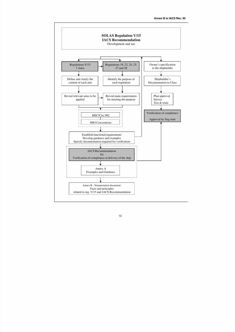
8/2/2019 Iacs Bridge Design,Equipmenr Arrangement and Procedure.
http://slidepdf.com/reader/full/iacs-bridge-designequipmenr-arrangement-and-procedure 72/80
Annex B to IACS Rec. 95
13
SOLAS Regulation V/15
IACS RecommendationDevelopment and use
Owner’s specification
to the shipbuilder
Shipbuilder’s
Documentation to Class
Plan approval
Survey
Test & trials
Reveal relevant aims to be
applied
Identify the purpose of
each regulation
Reveal main requirements
for meeting the purpose
Define and clarify the
content of each aim
Regulations 19, 22, 24, 25,
27 and 28
Regulations V/15
7 Aims
Establish functional requirements
Develop guidance and examples
Specify documentation required for verification
IACS Recommendation
for
Verification of compliance at delivery of the ship
MSC/Circ.982
IMO Conventions
Annex B - Interpretation document:
Facts and principles
related to reg. V/15 and IACS Recommendation
Verification of compliance
Approval by flag state
Annex A
Examples and Guidance
8/2/2019 Iacs Bridge Design,Equipmenr Arrangement and Procedure.
http://slidepdf.com/reader/full/iacs-bridge-designequipmenr-arrangement-and-procedure 73/80
Annex B to IACS Rec. 95
Appendix 1
of Annex B, IACS Recommendation 95
SOLAS Regulation V/15
Clarification of the content of each aim
The Aims of SOLAS Regulation V/15……………………………………………………………………. 15
Aim 15.1…………………………………………………………………………………………………….. 15
Aim 15.2…………………………………………………………………………………………………….. 17
Aim 15.3…………………………………………………………………………………………………….. 17
Aim 15.4…………………………………………………………………………………………………….. 18
Aim 15.5…………………………………………………………………………………………………….. 19
Aim 15.6…………………………………………………………………………………………………….. 20
Aim 15.7…………………………………………………………………………………………………….. 20
8/2/2019 Iacs Bridge Design,Equipmenr Arrangement and Procedure.
http://slidepdf.com/reader/full/iacs-bridge-designequipmenr-arrangement-and-procedure 74/80
Annex B to IACS Rec. 95
15
The aims of SOLAS regulation V/15
In the following, the aims of regulation 15 are defined and clarified to establish a common
understanding of the content of the individual aims, enabling a common approach in meetingthe aims as specified in the regulation.
A view of the full extent of the aims is regarded essential for safeguarding that the aims are
correctly applied within the areas of bridge design, the design and arrangement of navigational
systems and equipment on the bridge and bridge procedures when applying the regulationsaddressed in regulation 15.
AIM 15.1
Facilitating the tasks1 to be performed by the bridge team and the pilot 2 in making fullappraisal of the situation and in navigating the ship safely under all operational conditions
3
1 Overall functions to be performed
- Route planning- Navigation
- Traffic surveillance
- Manoeuvring
- Docking- Manual steering
- Conning- Internal and external communication related to the tasks to be performed
- Pilotage
2 Basic functions and tasks performed by the bridge team
(based on equipment carriage requirements and regular manning)
Officer in charge of the navigational watch:
- Navigation - Position-fixing by
o optical system
o radar systemo reading ship’s position from display
o plotting ship’s position
o visual observations
o monitoring - automatic pos.-fix. in electronic chart- Route keeping
o Adjusting ship’s heading to follow route
o Monitor automatic route-keeping- Traffic surveillance
o Monitoring radar/ARPA
o Conning
8/2/2019 Iacs Bridge Design,Equipmenr Arrangement and Procedure.
http://slidepdf.com/reader/full/iacs-bridge-designequipmenr-arrangement-and-procedure 75/80
Annex B to IACS Rec. 95
16
- Collision avoidance
o Adjusting ship’s heading and speed in relation to traffic- Manoeuvring
- External and internal communication related to safety in bridge operations
Rating assisting the watch officer:- Visual look-out
Navigator assisting the watch officer (or watch officer assisting the master):- Navigation - Route monitoring
- Position-fixing- Plotting ship’s position
- Adjusting course
- Monitoring the waters
Rating relieving the automatic heading control:
- Manual steering
Pilot assisting in safe navigation:- Conning and determination of heading and speed in relation to waters and
traffic
- Position-fixing and traffic surveillance by available means- Communication
3 Operational conditions and situations
Normal condition:
When all shipboard systems and equipment related to primary bridge functions
operate within design limits and weather conditions or traffic do not causeexcessive operator workloads.
Irregular condition:
When external conditions cause excessive operator workloads requiringqualified assistance on the bridge.
Abnormal condition:
When internal technical system failures require operation of basic back-upsystems or when they occur during an irregular operating condition, or when
the officer of the watch becomes unfit to perform his duties and has not yet
been replaced by another qualified officer.
Emergency situation:
When failure of internal ship systems not affecting the ability of navigation or
manoeuvring, or fire incidents occur which need to be controlled and managedfrom the bridge.
Distress situations:
When the ship has lost its navigating or manoeuvring ability.
8/2/2019 Iacs Bridge Design,Equipmenr Arrangement and Procedure.
http://slidepdf.com/reader/full/iacs-bridge-designequipmenr-arrangement-and-procedure 76/80
Annex B to IACS Rec. 95
17
3.1 Example of bridge team composition under different operational conditions
Reference which may be used for the purpose of design only:
Normal: watch officer - Darkness: + rating
Irregular: watch officer + assisting navigator (+ rating)
Abnormal: master + watch officer + look-out (+ helmsman)Emergency: master + watch officer + assisting navigator + look-out (+ helmsman)
(+ chief engineer/chief officer)
A pilot may be included in any of the above manning examples.
AIM 15.2
Promoting effective and safe bridge resource management 1
1 Factors promoting safe resource management include:
- Organized distribution of tasks and responsibilities
- Functional workplace arrangement suiting different operational conditions, task distribution and task performance
- Instant availability of instruments and equipment necessary for efficient
performance
- Qualifications and fitness of individuals- Procedures for safe operations
AIM 15.3
Enabling the bridge team and the pilot to have convenient and continuous access to essential
information1 which is presented in a clear and unambiguous manner, using standardized
symbols and coding systems for controls and displays 2
1 Essential information (and controls) required by the bridge team
The information and controls required, as well as what is to be regarded essential, arelinked to the type and importance of tasks to be carried out by the individual members
of the bridge team and the pilot.
The table showing Task and Means, which is included in chapter B 1 of the
Recommendation identifies the essential information required. Easy access to
information may be provided by outfitting and placing the workstations for efficient
task performance by members of the bridge team in accordance with the content of chapter C 3.
8/2/2019 Iacs Bridge Design,Equipmenr Arrangement and Procedure.
http://slidepdf.com/reader/full/iacs-bridge-designequipmenr-arrangement-and-procedure 77/80
Annex B to IACS Rec. 95
18
2 Presentation of information and standardization
Requirements addressing presentation of information and coding of systems for
controls and displays for equipment required to be carried are regulated by IMOperformance standards and IEC test standards.
AIM 15.4
Indicating the operational status 4
of automated functions1
and integrated components 2 ,
systems and/or sub-systems 3
1 Relevant automated functions include:
- Steering a set course
- Plotting ship’s position in an electronic chart system- Steering along a planned route governed by ship’s position
- Adjusting the speed according to ship’s position and pre-set values
- Manoeuvring operations (Semi automatic/Joystick)
2 Relevant integrated type approved components may include:
- Heading control unit- Satellite position-fixing unit (GNSS/GPS)
- Electronic chart display unit (ECDIS)
- Radar display unit
- Track control unit- Speed control unit
3 Relevant systems include:
- Track control system
- Integrated navigation systems (INS), including
- Grounding avoidance system for automatic route-keeping
4 Indicating the operational status (of automated functions and integrated components,
systems and/or sub-systems)
Indication of operational status is provided by:
- supplying continuous information of relevant system activities related to theship’s course, speed, propulsion, steering and operating mode on one individual
display
- enabling continuous visual observation of key values
- enabling checking of the functioning of system elements and operational
performance
8/2/2019 Iacs Bridge Design,Equipmenr Arrangement and Procedure.
http://slidepdf.com/reader/full/iacs-bridge-designequipmenr-arrangement-and-procedure 78/80
Annex B to IACS Rec. 95
19
- enabling early detection of deviations from planned operations and system
specifications
Categories of indications that may be included:
Normal operation:- Available components in the total system configuration
- Configuration in use
- Activity status of individual components in use- Second mode of operation at system failure, preferably based on system failure
mode, effect and criticality analysis (FMEAC)
Early warning:
- Reduced accuracy
- Reduced reliability of integrated system performance- Reduced reliability of propulsion and steering system
Alarm conditions:
- Equipment malfunction- System failure
- Display freeze
Operational warnings:
- Danger of collision
- Danger of grounding
- Weather conditions
AIM 15.5
Allowing for expeditious, continuous and effective information processing and
decision-making1
by the bridge team and the pilot 2
1 Conditions allowing effective information processing and decision-making:
- When all information required for evaluation and decision-making is clearly
presented and available at the location where action is to be taken on the
decision made, including appropriate feedback on actions taken and updatedinformation for continuous consideration.
- When information and equipment for performance of functions to be carriedout by different members of the bridge team are available at specific
workstations located for close co-operation.
2 See AIM 15.1, item 2
8/2/2019 Iacs Bridge Design,Equipmenr Arrangement and Procedure.
http://slidepdf.com/reader/full/iacs-bridge-designequipmenr-arrangement-and-procedure 79/80
Annex B to IACS Rec. 95
20
AIM 15.6
Preventing or minimizing excessive or unnecessary work and any condition or distraction on
the bridge which may cause fatigue or interfere with the vigilance of the bridge team and the pilot
1
1 Conditions that may interfere with the vigilance of the bridge team include:
- Poor working environment caused by unsuitable colours, lighting, ventilationand temperature, including excessive noise and vibrations from machinery
- Poor bridge layout, allocating workstations and areas for non-navigational
functions too close to the navigation area
- Insufficient provision of information for decision-making at the workstation,forcing the need to leave essential information or equipment at the workstation
when in need of additional information or controls located elsewhere
- Lack of harmonization of workplace functionality
- Presence of unauthorized persons on the navigation bridge
- Heavy workloads
AIM 15.7
Minimizing the risk of human error and detecting such error if it occurs1 , through
monitoring and alarm systems 2 , in time for the bridge team and the pilot to take appropriate
action 3
1 Factors minimizing human error include:
Workplace related:- Functionality
- Information availability
- System reliability
- Human/machine interface- Architecture of automation systems based on fail-to-safe philosophy with
simple and reliable second mode of operations
Human related:
- Competence
- Attitude
Operational:
- Manning
- Working routines
- Allocation of task(s) in relation to competence

8/2/2019 Iacs Bridge Design,Equipmenr Arrangement and Procedure.
http://slidepdf.com/reader/full/iacs-bridge-designequipmenr-arrangement-and-procedure 80/80
Annex B to IACS Rec. 95
- Detection of inappropriate performance
2 Monitoring and alarm systems
Systems and methods enabling detection of human error and timely warning for
appropriate action include:
- Monitoring and alarm transfer systems, monitoring personal activity and lack
of response on operational warnings and alarm conditions related to safety of navigation and transfer of unacknowledged warnings and alarms to a qualified
person
3 In time for appropriate action
Conditions affecting the time for appropriate action:
Operational warnings
- time to danger of collision and grounding (distance/speed)
- time to be allowed for required action


![Iacs Standard[1]](https://img.pdfslide.us/doc/110x75/54774576b4af9f76108b46d1/iacs-standard1.jpg)