Embed Size (px)
Citation preview

i.’ ‘\ , ,- __ .-
.- ,/. ‘-.,
i
-,,\ (,. -kx Me by the Superintendent of Documents. U. 5: Government Printing Office, Washington 25. D. C. Yearly snbseriptiy, $3; f6reign. $4.50; :, i _
, ^ ‘. -.. j’
single copyprice varieeaccydink to size?. - - y - - - - - - Price lt?cents-,,
-1 \’ ’ ,
‘\ L ._ I: 1, \y 1 i,,:; ..’ : ’ .--
‘-y ‘. :‘:.Y’, ,y, .- (]_;,_
,~ . ~~.
-, ..,- -. _ , \ ,~’ ,, -2 -. :. .:,- ,. t ._. . -.- ‘. ,---.

-- .- .- ,- _/- .- u
y ’ ;i --I. ~-

REPORT 932
EFFECT OF REYNOLDS NUMBER IN TURBULENT-FLOW RANGE ON FLAME SPEEDS OF BUNSEN
BURNER FLAMES
By LOWELL M. BOLLINGER and DAVID T. WILLIAMS
Flight Propulsion Research Laboratory Cleveland, Ohio

National Advisory Committee for Aeronautics Beadpzcarters, r7.24 F Street NW., Washington 25, D. C.
Created by act of Congress approved March 3,1915, for the supervision and direction of the scientific study of the problems of flight (U. S. Code, title 50, sec. 151). Its membership was increased from 12 to 15 by act approved March 2,1929, and to 17 by act approved May 25,1948. The members are appointed by the President, and serve as such without compensation.
JIXOME C. HUNSAICER, SC. D., (‘ambridge, Mass., Cltcl iman
ALEXSNMX WICTMO~~ SC. D., Secretary, Smithsonian Institute, Trite Chairmun.
HON. JOHN R. ALISON, Assistant Secretary of Commerce. DETLEV W. BRONIC, PH. I)., I’resident, Johns Hopkins University. KARL T. COMPTON, PH. D., Chairman, Research and Development
Board, Department of Defense. EDWARD U. CONDON, PH. D., Director, National Bureau of
Standards. JAMES H. DOOLITTLIZ, SC. D., Vice President, Shell Union Oil
Corp. R. M. HAZEN, B. S., Director of Engineering, Allison Division,
General Motors Corp. WILLIAM LITTLEWOOD, M. E., Vice President, Enginerring,
American Airlines, Inc. THEODORE C. LONNQUEST, Rear Admiral, United States Navy,
Deputy and Assistant Chief of the Bureau of Aeronautics.
I)ONAL~ L. I’UTT, Major General, Uuitetl States Air Force, Director of Research and Development, Oflice of the Chief of Staff, MatCriel.
JOHN D. PRICE, Vice Admiral, United States Navy, Vice Chief of Naval Operations.
ARTHUR E. RAYMOND, So. D., Vice President, Engineering, Douglas Aircraft Co., Inc.
FRANCIS W. REICIIELDERFER, SC. D., Chief, United States Weather Burrau.
Hos. DELOS W. RENTZEI,, Administrator of Civil Aeronautics, Department of Commerce.
HOYT S. VANDENIIEIIG, General, Chief of Staff, United States Air Force.
THEODORE I’. WBIGHT, SC. D., Vice President for Research, Cornell University.
HWGH L. DRYDEN, PH. D., Ui?~~tor JOHN F. VIC~~ORY, LL.M., Execzctive Secretary
JOHN W. CROWLEY, JR., B. S., Associate Director for Research E. H. CHAMBERLIN, Execzltive O.Qicer
HENRY J. E. REID, D. Eng., Director, Langley Aeronautical Laboratory, Langley Field, Va.
SMITH J. DEFRANCE, B. S., Director, Alues Aeronautical Laboratory, Moffett Field, Calif.
EDWAW R. SIIARP, SC. D., Director, Lewis Flight Propulsion Laboratory, Cleveland Airport, Cleveland, Ohio
TECHNICAL COMMITTEES
AERODYNAMICS OPERAYING PROBLEMS POWER PLANTS FOR AIRCRAFT IXDUSTIIY CONSULTING AIIXCRAFT CONS~RUCXION
Coord~imztion of Research Needs of MiZitmy nnd Civil Aviution Prepa~trtio~l of Rcsca~~cl~ P~‘OVYHIU
AlloccctZori of ProUems Pwvention of D?Lplication
Consideration of Inventions
LANGLEY AERVNAUTICAL LA~~&%T~RY, LEWIS FLIGHT PROPULSION LABORMORY, AMES AERONAUTICAL LABOR-ITORY,
Langley Field, Va. Cleveland Airport, Cleveland, Ohio i\Ioffett Field, Calif.
Conduct, under unified control, for all agelacies, of scientific research on tlrc fmda~m~Lta1 problellls of flight
OFFICE OF AERONAUTICAL INTELLIGENCE Washington, D. C.
Collection, classificcctiolr, conrpiltrtion, tr~tl dissemination of scicwtific trnd tcch?lictrZ infortlftrtion on trrronrrlftics
II

REPORT 932
EFFECT OF REYNOLDS NUMBER IN TURBULENT-FLOW RANGE ON FLAME SPEEDS OF BUNSEN BURNER FLAMES
By LOWELL M. BOLLINGER and DAVID T. WILLIAMS
_ SUMMARY
The effect of $zw conditions on the geometry of the turbulent Bunsen same was investigated. Turbulent jlame speed is de-
jined in terms of flame geometry and data are presented show- ing the effect qf Reynolds number of flow in the range of 3000 to 36,000 on flame speed for burner diameters from )i to I$6 i.nches and three .fuels-acetylene, ethylene, and propane.
The normal jlame speed of an explosive mixture WUR shown. to be an important factor in determining its turbu1en.t $ame speed, and it W&S deduced .from the data that turbulent jlarne speed is a function of both the Reynolds number qf the turbulent
fow in. the burner tube and qf the tube tlia.metfr.
INTRODUCTION
A flame advancing through an rsplosivc mixture at rest or in laminar flay assumes, at least initially, a smooth com- bustion front. The speed normal to the front and relative to tile dtljacrnt, unburned mixture with which this froilt ad- vm~es is known as tbc normal flame spcctl of the mixture (or transformation velocity). This speed is constn.nt for. a given set of physical and chemical conditions.
In turbulent flow, the combustion front is not smooth bc- cause it is disturbed by the fluctuating components of vc- locity. Yet if a surface sufficiently largr in comparison with the scale of turbulcncr is considered, the average position of the combustion front atlvanccs with some dcfinile spc~l normally to itself. This spectl will bc callctl thr t~l~~*l~lllc~l~
flame spcctl and its value will probably dcpcnd upon the aerodynamic as well as the physical and chrmical conditions of the cxplosivc mixture.
Because turbulence can greatly increase the rate of burn- ing of fuel-air mixtures, an exact knowledge of the influence of turbulence on combustion is highly important to practical applications. Some information has been gathered from tests on internal-combustion engines (reference 1). In these investigations, no attempt was made to relate the rate of burning to any fundamental measurable property of the turbulence. The degree of turbulence of the charge in the engine cylinder was varied by changing engine speed or cylinder geometry. Two investigators, Damlr6hler (refcr- ence 2) and Shelkin (reference 3), each have proposecl a theory to relate flame speed to turbulence. These theories require evaluation with experimental data obtained under well-defined conditions.
863468-X1
A possible method of investigating the relation between turbulence and rate of burning is by measurement of rate of flame propagation in a steady-flow Bunsen type burner. .It is possible in such an apparatus to create forms of turbulence that have been quantitatively investigatecl. Furthermore, it is common to cletermine normal flame speed as the volume rate of flow of explosive mixture clividecl by the surface area of the inner cone of a laminar Bunsen burner flame. (See reference 4 for a discussion of the method.) This technique for measuring flame speed can also be used in the range of turbulent flow. DamkGhlcr (reference 2) carried out some mcasurcments in this manner, but his data arc insufficient to establish conclusively a theory.
In experiments conducted at the NACA Cleveland labo- ratory during 1945, flame speeds were experimentally deter- mined by the Bunsen burner technique with fully developed turbulent flow in the burner tubes. Data were obtained for three fuels, for burner diameters from >i to 1)6 inches, and for Reynolds numbers in the range from 3000 to 35,000. In order to show the cfl’ect of turbulence on flame speed, t.hcsc turbulcut flame spcctls were correlated with normal flame spertl, tube tliamctcr, and Reynolds number. In addition, the results wcrc compared with the theories of rclfcrenccs 2 and 3.
APPARATUS AND PROCEDURE EQUIPMENT
The apparat.us used in this investigation is diagrammati- cally shown in figure 1. Fuel and airwerc metcrcd separately, then thoroughly mixed, and conducted into the Bunsen burner tube, which was long enough for fully developed turbulent flow to result at the burner outlet. The burners used were a series of four smooth seamless steel tubes, which had the following dimensions :
Nominnl Inside Ratio of diameter diameter, d
Length, L length to (in.) (cm) (cm) inside dinm-
eta, L/d
____
$6 0. G2G 125 $6 ,943 215 iti
1s: : 2.843 1. X9 215 21.5 13G 7G I I I
The tubes were cooled to room temperature by water jackets. In order to prevent blow-off of the Bunsen flame at high
flows, it was necessary to surround it by an auxiliary flame.

2 REPORT 932-NATIONAL ADVISORY COMMITTEE FOR AERONAUTICS
---Burner fube
Fmum :.-Diagram of burner air-fuel system.
An annular-shaped burner was formed around the lip of the Bunsen burner by surrounding it with a tube of somewhat larger diameter. A fuel-air misture at low velocity flowed through this auxiliary burner; the fuel in the auxiliary burner was the same as that in the main burner. This mixture burned at the outlet of the burner and kept the inner Bunsen flame seated to the lip. The auxiliary flame was always kept as low as possible so as to reduce bo a minimum the errors caused by this flame. The auxiliary flame seemed to have no appreciable effect on the main body of the Bunsen flame in that, where flow conditions permitted, no change could be noticed in the Bunsen flame when the auxiliary burner was suddenly shut off.
FUELS
Measurements were made using three commercial-grade fuels-acetylene, ethylene, and propane. Because acetylene is dissolved in acetone in the tank, an appreciable amount of acetone is present in the gaseous fuel. Most of this acetone was removed by bubbling the acetylene-acetone gaseous mixture through flowing water. The combustion air used came from the laboratory service air supply, which, when expanded, had a relative humidity of approximately 15 percent. No temperature control was used; very little variation of temperature, however, was observed.
METHOD OF MEASURING FLAME SPEED
The combustion zone of a laminar Bunsen flame is thin and clear-cut, but that of a turbulent Bunsen flame consists of a “brush” of flame having a roughly conical shape but apparently formed of a rapidly fluctuating, much folded surface (fig. Z(a)). Nevertheless, certain surfaces can be identified in the turbulent flame; for example, in figure 2(b) an inner and outer envelope of the flame and a mean surface are indicated. A flame speed corresponding to each of these surfaces may be determined. Although Damkijhler (reference 2) believed that the inner and outer envelopes are related to the turbulcnt8 and normal flame speed, re- spectively, it is considered herein that the flame front has some average position around which it fluctuates; the degree of fluctuation determines the position of the inner and outer
(a) Flame.
- Bour.w’aries of flame brush: -- --;;Lo%; of.ffm+ mean
:.
(b) Flame showing brush and flame mean surface outlined.
FIOURE Z.-Turbulent Bunsen burner flame. Nominal diameter of burner, 96 inch; ethyl- ene gas in air.
envelopes. The turbulent flame speed should then be that flame speed corresponding to the surface that is the average position of the flame front, or
ut= Q/S (1) where ut turbulent flame speed Q volume rate of flow S surface area of mean position of burning The volume rate of flow was obtained from the flowmeter readings. The surface area of any given turbulent flame was determined in the following manner: The flame was photographed on 5- by 7-inch film wit.h an exposure time of about 2 seconds. An average flame surface was drawn on the negative of the photograph and an attempt was made to draw the surface halfway between the inner and outer envelopes of the flame brush (fig. 2(b)). The surface area was then determined by the approximate equation for cone- like surfaces of revolution.
S=rA;
where A area of longitudinal cross section of flame as photographed L length of generating curve, excluding base, of cone-like
surface
EFFECT OF REYNOLDS NUMBER IN TURBULENT-FLOW RANGE ON FLAME SPEEDS 3
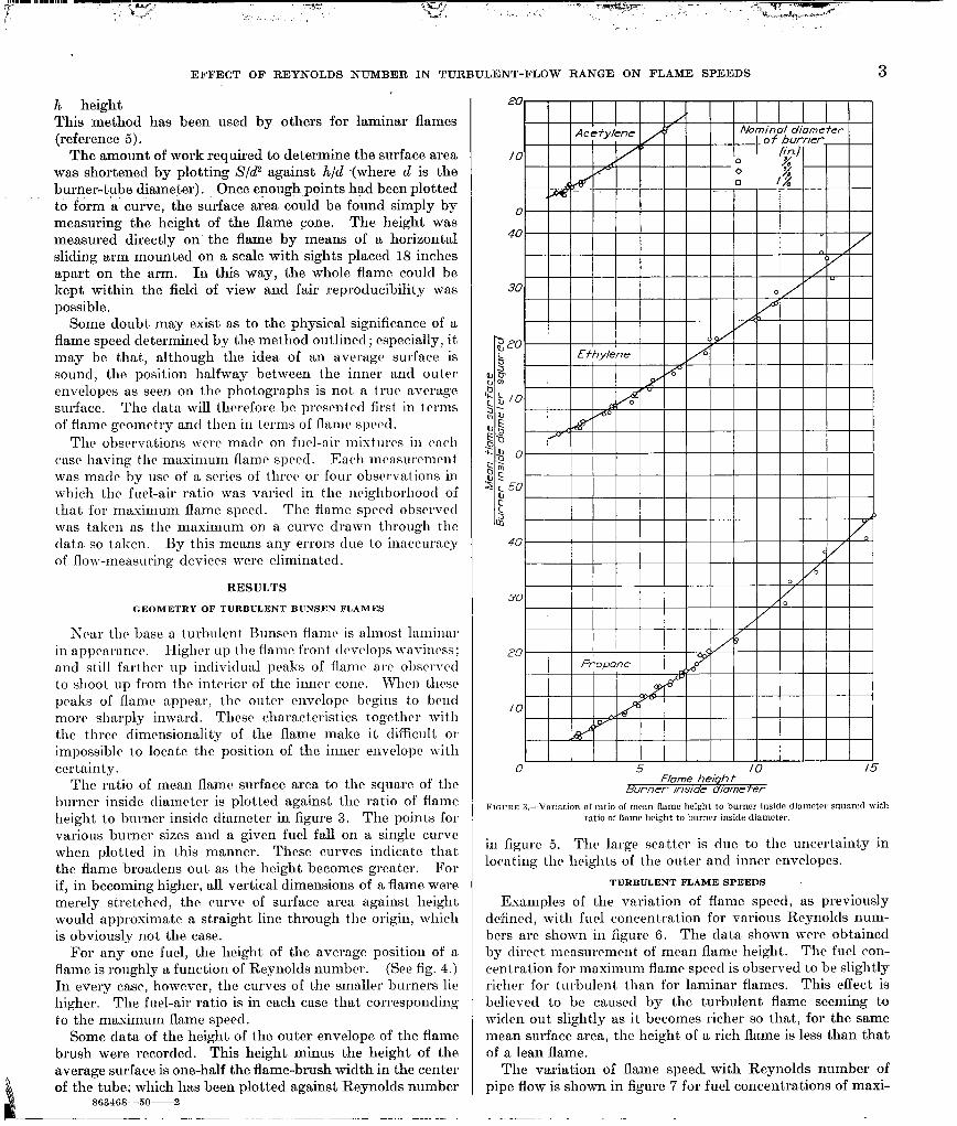
h height This method has been used by others for laminar flames (reference 5).
The amount of work required to determine the surface area was shortened by plotting S/d2 against h/d (where d is the burner-tube diameter). Once enough points had been plotted to. form ‘a curve, the surface area could be found simply by measuring the height of the flame cone. The height was measured directly on the flame by means of a horizontal sliding arm mounted on a scale with sights placed 18 inches apart on the arm. In this way, the whole flame could be kept within the field of view and fair reproducibility was possible.
Some doubt may exist. as to the physical significance of a flame speed determined by the method outlined; especially, it. may be that, although the idea of an average surface is sound, the position halfway between the inner and outer envelopes as seen on the photographs is not a true average surface. The data will therefore bc prcscntctl first in terms of flame geometry ant1 then in terms of flame spcctl.
The observations wcrc made on fuel-air mixtures in each cast having the maximum fiamc spcrd. Each mcasuremcnt was matlc by use of a series of three or four observations in which tbc fuel-air ratio was varied in the ncigbborhood of that for maximum flame speed. The flame spctd observed was taken as the maximum on a curve drawn through the data so taken. By this means any errors clue to inaccuracy of flow-measuring devices were eliminated.
RESULTS
GEOMETRY OF TURBULENT BUNSEN FLAMES
Near the base a. turbulent Bunsen flame is nhnost laminnl in nppcarancc. H’gl i icr up the flame front tlrvclops waviness; and still farther up individual peaks of Ranic are observed to shoot up from the interior of the inner cone. When t,licse peaks of flame appear, the outer envclopc begins to bend more sharply inward. Thcsc characteristics togctbcr with the three dimcnsionality of the flame make it difficult 01 impossible to locate the position of the inner envclopc with certainty.
The ratio of mean flame surface area to the square of the burner inside diameter is plot.tcd against the ratio of flame height to burner insiclc diameter in figure 3. The points for various burner sizes and a given fuel fall on a single curve when plotted in this manner. These curves inclicatc that. the flame broaclens out as the height becomes greater. For if, in becoming higher, all vertical dimensions of a flame were merely stretched, the curve of surface area against height would approximate a straight line through the origin, which is obviously not the case.
For any one fuel, the height of the average position of a flame is roughly a function of Reynolds number. (See fig. 4.) In every case, however, the curves of the smaller burners lie higher. The fuel-air ratio is in each case that corresponding to the maximum flame speecl.
Some data of the height of the outer envelope of the flame brush were recorcled. This height minus the height of the average surface is one-half the flame-brush width in the center of the tube; which has been plotted against Reynolds number
863468-50~2
20
10
Acetylene Afominal diomatar ’ qf burner
f;;y!
, I I I
0 5 f0 /5 Flame heiqh f
Burner ins/de d/ome fer
FIGURE 3.-Variation 01 mtio of mean flame height to burner inside diameter s:luared with ratio of flame height, to burner inside diameter.
in figure 5. The large scatter is clue to the uncertainty in locating the heights of the outer and inner envelopes.
TURBULENT FLAME SPEEDS
Examples of the variation of flame speed, as previously defined, with fuel concentration for various Reynolds num- bers arc shown in figure 6. The data shown were obtained by direct mcasurcmcnt of mean flame height. The fuel con- centration for maximum flame speecl is observed to be slightly richer for turbulent than for laminar flames. This effect is belicvecl to be causrcl by the turbulent flame seeming to wiclcn out slightly as it becomes richer so that, for the same mean surface area, the height, of a rich flame is less than that of a lean flame.
The variation of flame speed with Reynolds number of pipe flow is shown in figure 7 for fuel concent,rat,ions of maxi-

4 REPORT 932-NATIONAL ADVISORY COMMITTEE FOR AERONAUTICS
Nominal diame fer of burner
(in. / P %
20
I#
: % 78
0 ‘y I I I II III II I I I I I I I I I I II I III1 !
py/
25
III III l l I l 11 l I l l I I I 1 I I I I I I I I I I I I II 0
I 5 IO I5 20 25 30 35 40x103
Reynolds number
FIGURE 4.-Vnrintion of mcnn flame height with Reynolds number.
0 5 IO I5 20 25 30 35 40x/05 Reynolds number
mum flame spectl. V 1 u ucs of normal flame spiwl 11,~ from reference 4 arc indicated for the three fuels hi- points on the ordinate. Rc_vnolcls number of flow is, l~o~vcv~~r. not ncccs- sarily clescriptire of turbulence at the flame front. The tlntn
;30
/20 0 Reyno(ds number
F - 33,700 I 0 I
60 / b
,
sol 4
I I I I 5 6 7 8 9 /O
Percenf fue I
01 figure 7 were obtninctl both by photographing the flame a~ltl by direct measurement of flamr height; in both c’ascs the mean surface aren was obtained from the CIII~CS in figurt~ :;.

IO 20 30 Reynolds number of pipe flow
FIGI:RE 7.-Vwiation of flame speed with Reynolds number of flow. (Sormal fhnnw slwrd IL” from rererence 4.)
DISCUSSION NATURE OF TURBULENCE IN PIPE FLOW
The fact that the flame speed as defined in turbulent flow cannot be determined with very high accuracy is a circum- stance that is implicit in the very nature of turbulence. The results of the measurements are principally an identi- fication of certain trends in turbulent flame speed as sum- marized. It is thus desirable to identify the nature of the turbulence in which the measurements were made.
The theory of turbulent flow in general is reviewed in references 6 to 8. It is concluded in the theory, particularly in reference 8, that a scale factor and an intensity of turbu- lence are sufficient to characterize isotropic turbulence. These two factors have been measured in various ways. The turbulent intensity based on longitudinal turbulent motion is shown in dimensionless form in figure 8, as measured between two infinite planes (reference 9); the distribution is expected to bc similar to that in a tube. It is notable that the turbulcncc in the tube is not completely isotropic so that the mean turbulent intensities arc different in dif- fcrcut directions.
Tht mixing length has also been measured and is shown in figure 8 as puhlishctl in Icfcrc>ncc 6. It is cviclrnt that both
c The points representing data taken by direct mcasure- ment are the maximum flame speeds from curves like those of figure 6 and are therefore, in most cases, averages of several measurements. Most of t(lie points representing photographic data are averages of two separate flame-speed determinations. The large scatter of the acetylene flame speeds for the $&inch-diameter burner at low Reynolds numbers is believed due to t#he fact. t.hat, because the flame was small, a small absolute error in height measurement resul t.ed in a large relative error.
The data of figure 7 show several consistent characteris- tics. For any one explosive mixture, the turbulent flame speeds are, in general, greater than the normal flame speed; for a given Reynolds number, the flame speed increases wit11 increasing burner diameter. In general, flame speed in- .5-
Distance- from wall Ill ..-
creased with Reynolds number but at a decreasing rate, and at the larger values of Reynolds number, flame speed Tube radius
approached asymptotically a linea,r relation with Reynolds FIGURE 8.-Representative distribution across tnhe of turbulmt intensity -\islu (referonce
number. 9) and mixing length (reference G). (Root-mrau-square fluctuating component of velocity 4%; mean gas-flow velocity Cr..)
i
lb- __-,.__.., ,,. -.-_.,-. .,, , . ..,,. , ---,...,,-..I- ..,a .,m,.m-.-.m. . ..I m.mm..I-.---..-I.I II I I. I ,111 1..1111111
0

6 REPORT 932--NATIONAL ADVISORY COMMITTEE FOR AERONAUTICS
mixing length and turbulence vary widely across the flow. It follows that, insofar as the turbulent flame speed is to be associated with the nature of the turbulence, it is a mean flame speed that is associated with an average type of tur- bulence in the gas issuing from a uniform tube.
In measurements of flame speed in turbulent flow, the scale of the turbulence in the tube is proportional to the size of the tube; the intensity component is proportional to the mean gas flow velocity, as follows from the general similarity relation.
THEORIES OF TURBULENT FLAME SPEED
Damkijhler (reference 2) in an attempt to determine the effect of turbulence on flame speed presents some data obtained from a Bunsen propane-oxygen flame on a burner tube that was long enough to have fully developed turbulent flow. It was found that flame speeds corresponding to the outer envelopes were approximately equal to the normal flame speed of the mixture. The flame speed corresponding to the inner envelope was assumed to be the turbulent flame speed. The ratio of the Aamc speeds corresponding t.o the inner and outer envelopes was therefore considered equal to the ratio of turbulent flame speed to normal flame speed. Results from three burners of 1.385-, 2.180-, and 2.71% millimeter diameters were obtained. The flame-speed ratio was then shown by somewhat limited clata to vary linearly with the square root of the Reynolds number @ for the two smaller tubes in the range 2300<Re<5000 and linearly with Re for the two larger tubes in the range 5000 <Re<18,000.
In the discussion of results of reference 2, two conditions of turbulence are considered that depend on whether the scale of the turbulence is much greater or much less than the thickness of the laminar flame front. Fine-scale tur- bulence was considered to influence the rate of diffusion between the burned and unburned gas without roughening the flame front, and large-scale turbulence was considered only to roughen the flame front, thus increasing its surface area. The theory developed attempted to show that for fine-scale turbulence, -
Ut -= - U7L J
E (3) V
and that for large-scale turbulence
where
UIN % (4)
c turbulent diffusion coefficient v kinematic viscosity of explosive mixture
The turbulent diffusion coefficient E is an empirical factor that was devised to clcvelop a theory for the turbulent- velocity distribution in a pipe or tube. By analogy w-i th the molecular diffusion coefficient, it is written as
E=l VU2 (5) whcrr
1 so-called mixing length: scale factor &i” rootmean-square fluctuating component of velocity
In the Karman theory of pipe turbulence, the factors com- prising e enter into the theory as empirical parameters evaluated from the velocity distribution, but equivalent or analogous quant,ities are directly measurable. It has been shown by direct observation that in turbulent pipe flow, 42 varies as the mean gas velocity, and that the scale, and therefore presumably I, varies as the pipe diameter. Both quantities are hardly approximately constant across the flow; but in predicting the results of any experiments dependent on et it is apparent that mean E must vary as the Reynolds number of the pipe flow.
In reference 2, it is considered that the smallest burner used gave fine-scale turbulence; whereas the largest burner gave large-scale turbulence, the difference of which was believed to account for the difference in the dependence of flame-speed ratio on Reynolds number.
A theoretical analysis of the effect of turbulence on flame speed is presented in reference 3. The two cases of fine-scale and large-scale t,urbulence are again considered. Based upon the same considerations as in reference 2, the expression for turbulent flame speed uL in fine-scale turbulence was derived
(6)
where K is the thermal conductivity due to molecular motion. For the case of large-scale turbulence, the expression for
U, was derived to be
(7)
where I! is a nondimensional coefficient and is approximat,ely unity. It should be noted that flame speed for large-scale turbulence is here predicted to be independent of the scale of turbulence and to be independent of the normal flame speed if the mean square fluctuating component of velocity U” becomes great compared to u,~.
COMPARISON WITH THEORIES OF EFFECT OF TURBULENCE ON FLAMF SPEED
According to the theories of refcrenc,es 2 and 3, the flame speed in turbulent flow is predicted to depend on the turbu- lent diffusion coeflicient E for small-scale turbulence. It has been shown that ~=l$? and that E should vary as the Rey- nolds number of flow Re inside the tube. If the change of E is neglected in the space between the tube outlet and the flame! it. follows that the turbulent flame speed is predicted for small-scale turbulence (a) in reference 2 to vary as u,dRe, and (b) in reference 3 to vary as u,Jl+kRe where k is a constant. Ac.tually the theories as presented mere some- what more specific in their predictions. The predictions of reference 3, for example, would seem to approximate those of reference 2 because the second term in the radical is much larger than 1.
Again for large-scale turbulence, the predictions arc that Aamc speed should vary as u,Re (reference 2) and as
U,L I--- 1 1 +B 2’ (reference 3)) where R is a constant of approxi-

EFFECT OF REYNOLDS NUMBER IN TURBULENT-FLOW RANGE ON FLAME SPEEDS 7
mately 1. For the range of the experiments, un is approxi- mately 1 foot per second, and U2 varies in the range of magnitude of u,,~.
Summarizing the results of the flame-speed measurements, figure 7 serves to give some fairly definite indications as to
L-a whether the theories mentioned are accurate. First, according to the theory of turbulence in pipes or
tubes, the mixing length of the turbulent flows used is approx- imately 0.1 inch, which is definitely greater than the 0.001 inch usually considered to be the approximate thickness of the laminar flame. The data show that: (a) The Reynolds number is inadequate alone to correlate the turbulent flame speed; and (b) in any case the variation of the turbulent flame speed with Reynolds number for a given tube is non; linear in the range of large-scale turbulence. It is seen that the results of this method of investigation differ from the theory of reference 2 concerning the dependence of flame speed on Reynolds number for large-scale turbulence in a Bunsen burner flame.
The turbulent intensities used arc certainly large enough to indicate whether the turbulent flame speeds tend to be independent of the nature of the fuel at large values of Z2. That is, t,he curves for various fuels are predicted in reference 3 to converge at higher Reynolds numbers; however, they show no sign of converging in the range of this investigation.
NATURE OF VARIATION OF TURBULENT FLAME SPEED
The data of figure 7 obviously require more than one correlation variable. The fuel, the velocity, and the burner diameter are one possible set of parameters; the fuel, the Reynolds number, and the burner diameter are a possible alternative choice. Reynolds number rather than velocity is used herein because of the general use of Reynolds number in the analysis of fluid behavior and because previous pro- posed theories used it. In any case, the choice of variables with which to correlate the data is arbitrary.
The general appearance of the data suggests uJu, as a possible variable to express the effect of the fuel.
A second trend is indicated by the fact that u1 at any value of Re is greater with larger tube diameter by a factor that varies proportionally with un.
A third phenomenon is indicated by the curvature of the various graphs, suggesting that uI might vary as a power of Reynolds number different from 1, for given fuel and burner diameter.
The data of figure 7 are used to fix the manner of variation of u1 in the form
where IL,= CunadbRec (8)
Ul turbulent flame speed, (cm/set) c constant, empirically determined from data UR normal flame speed, (cm/set) d burner diameter, (cm) Re burner Reynolds number based on mean air speed
and burner diameter a, b, c exponents, empirically determined from data The exponent of un is chosen by inspection as equal to 1.
The exponent of the diameter d is fixed by cross-plotting the data of figure 7. The flame speeds uI taken from the curves for the various tube sizes were compared for given Reynolds number and fuel. The comparison is shown in graphical form in figure 9. Relative flame speeds were compared for 11 different fuel-Reynolds number choices with relative diameter for the y&inch-dia.meter tube. The log plot is seen to be fairly representable as a straight line, though strictly speaking a slight curvature is noted through the points. The line as shown has a slope equal to 0.26
I I ,,,I,, I I III, .2 .3 .4 .6 .8 I.0 2 3 4 6 80
Relative dtame fer
FIGURE B.-Variation of rclntivc flame speed with relative burner diameter, based on $6inch burner.
so that the exponent b of the burner diameter in equation (8) is
b=O. 26
The value of the exponent c of Reynolds number in equation (8) is found by making log plots of the quantity
as a function of the burner-tube Reynolds number Re. The data for acetylene, cthylcne, and propane are plotted in fig- ures 10(a), 10(b), and 10(c), respectively. The lines con- sidered by inspection to represent the data most accurately are indicated on the curves. The three curves are shown on figure 10(d) with the curve obtained by averaging the three. The correlation represented by the average curve is suitable as approximating all the data. The scatter of experimental points is a little greater than would be antic- ipated from the methods used.
The equation of the average curve (fig. 10(d)) is
s=O.lS Re0.24 n
or u ,= 0.18 u,,d0.26 Re0.24 (10)
Any uncertainty as to the exact relation among the chosen variables might be removed by an extension of the experi- ments. It is possible, however, that the same kind of experimental uncertainty is to be anticipated in any study of turbulent flames.
The results here shown will suggest some approximate relations for use in future extensions of the theory. Thus, approximately
ua=%
uta fi u,a'JS

8 REPORT 932-NATIONAL ADVISORY COMMITTEE FOR AERONAUTICS
/ 2 3 4 6 8/O 20 30 40 60 80 /OOx/03 Burner - fube Reynolds number
(a) Acetylene in air. (h) Ethylene in air. (c) Propane in air. (d) Comparison of fuels.
FIQIJRE IO.- ,‘& as function of burner-tube Reynolds number. (Turbolmt flnmc n
speed II, cm/xc; normal flame speed IL”, cm/see; dinm. d. cm)
The direct dependence of turbulent flame speed on laminar flame speed is in agreement with reference 2.
SUMMARY OF RESULTS
From an investigation to determine the effect of Reynolds number in the turbulent-flow range on flame speeds of Bunsen burner flames, the following results were obtained:
1. A correlation of the flame speed in a Bunsen burner with several variables has been empirically derived in the
turbulent-flow range at sea-level atmospheric conditions in the form
u,=Q 1% d0-26Re0.24 . n where
Ut turbulent flame speed, (cm/set) %I normal flame speed (transformation velocity), (cm/set) d burner diameter, (cm) Re Reynolds number based on mean mixture speed and d
The experiments ranged from a Re value of 3000 to 35,000, tube diameters from 0.626 to 2.843 centimeters, and the fuels were acetylene, ethylene, and propane. The fuel-air mix- tures having maximum u, were used.
2. The results obtained, based on the mean flame surface, agreed with the theories of DamkChler on the effect of large- scale turbulence on the flame speed in a Bunsen burner flame as to the dependence on laminar flame speed, but differed as to the dependence on Reynolds number.
3. The data showed no tendency for turbulent flame speeds of different fuels to approach one another at high flow rates, as given by the theory of Shelkin.
FLIGHT PROPULSION RESEARCH LABORATORY, NATIONAL ADVISORY COMMITTEE .FOR AEROKAUTICS,
CLEVELAND, OHIO, June 30, 1948.
REFERENCES
1. Burk, R. E., and Grummitt, Oliver: The Chemical Background for Engine Research. Interscience Pub., Inc. (New York), 1943, pp. 38, 39.
2. DamkGhler, Gerhard: The Effect of Turbulence on the Flame Ve- locity in Gas Mixtures. NACA TM 1112, 1947.
3. Shelkin, Ii. I.: On Combustion in a Turbulent Flow. NACA TM 1110, 1947.
4. Smith, Francis A., and Pickering, S. F.: Measurements of Flame Velocitv by a blodified Burner Method. Res. Paper RP 900, Jour. ties. Nat. Bur. Standards, vol. 17, no. 1, July 1936, pp. 7-43.
5. Corsiglia, John: Xew Method for Determining Ignition Velocity of Air and Gas Mixtures. Am. Gas Assoc. Monthly, vol. XIII. no. 10, Oct. 1931, pp. 437-442.
G. Bakhmeteff, Boris A.: The Mechanics of Turbulent Flolv. Prince- ton Univ. Press (Princeton), 1941, p. 53.
7. Taylor, G. I.: Statistical Theory of Turbulcncc. Proc. Roy. Sot. London, ser. A, vol. CLI, no. A873, Sept. 1935, pp. 421-478.
8. Dryden, Hugh L.: A Review of the Statistical Theory of Tur- bulence. Quarterly Appl. Mat,h., vol. 1, no. 1, April 1943, pp. 7-42.
9. Prandtl, L.: Beitrag zum Turbulenz Symposium. Proc. Fifth International Congress for Appl. Mechanics (Cambridge), Sept. 12-16, 1943, pp. 340-346.

. . -_ : . . . \. .-, ‘,,_ ‘i -.
.s, - 1‘ 1. ,-. ,\;--- _:,to ,^ .-