Embed Size (px)
Citation preview

I2C CO2 SensorTechnical Guide
TABLE OF CONTENTS
SENSOR OVERVIEW ....................................................................................................................................... 3Features .......................................................................................................................................................................................3Environmental Requirements .......................................................................................................................................................3
WALL-MOUNTED SPACE CO2 SENSOR WIRING TO HVAC UNIT CONTROLLER ........................................ 4
DUCT-MOUNTED CO2 SENSOR MOUNTING & WIRING TO HVAC UNIT CONTROLLER ............................. 5
DUCT-MOUNTED CO2 SENSOR INSTALLATION ............................................................................................ 6
TROUBLESHOOTING ...................................................................................................................................... 8Setting The Sensor Address Switch .............................................................................................................................................8Using LEDs to Troubleshoot ........................................................................................................................................................8Altitude Correction ........................................................................................................................................................................8TB1 Terminal Block (CO2 Reading) ..............................................................................................................................................9
APPENDIX...................................................................................................................................................... 10Mounting Plate Dimensions........................................................................................................................................................10
AAON, Inc.2425 South Yukon Ave.Tulsa, OK 74107-2728www.aaon.comFactory Technical Support Phone: 918-382-6450Controls Support Phone: 866-918-1100
AAON P/N: G042470, Rev. 01FCopyright August 2019 AAON, Inc. AAON® is a registered trademark of AAON, Inc., Tulsa, OK.AAON assumes no responsibility for errors or omissions.This document is subject to change without notice.
PART NUMBER TABLE
PART DESCRIPTION AAON P/N
Wall-Mounted I2C CO2 Space Sensor ASM01824Duct-Mounted I2C CO2 Sensor (RA or SA) ASM01826I2C Digital Room Sensor Temp Only ASM01817I2C Digital Room Sensor Temp & Humidity ASM01818Mounting Plate G026490VCM-X E-BUS Controller ASM01702
This manual is also available for download from our website—www.aaon.com/controlsmanuals—under Previous Generation Sensors, where you can always fi nd the latest literature updates.
Technical Guide
CO2 SENSOR
3
Overview
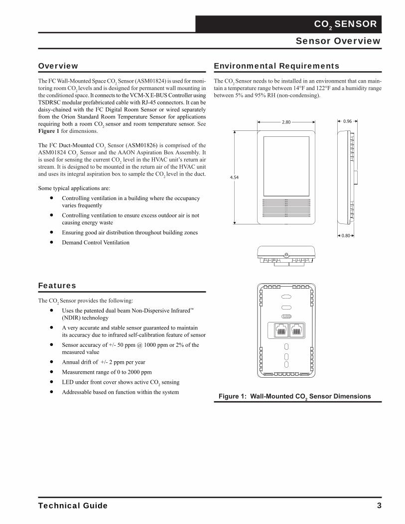
The I2C Wall-Mounted Space CO2 Sensor (ASM01824) is used for moni-toring room CO2 levels and is designed for permanent wall mounting in the conditioned space. It connects to the VCM-X E-BUS Controller using TSDRSC modular prefabricated cable with RJ-45 connectors. It can be daisy-chained with the I2C Digital Room Sensor or wired separately from the Orion Standard Room Temperature Sensor for applications requiring both a room CO2 sensor and room temperature sensor. See Figure 1 for dimensions.
The I2C Duct-Mounted CO2 Sensor (ASM01826) is comprised of the ASM01824 CO2 Sensor and the AAON Aspiration Box Assembly. It is used for sensing the current CO2 level in the HVAC unit’s return air stream. It is designed to be mounted in the return air of the HVAC unit and uses its integral aspiration box to sample the CO2 level in the duct.
Some typical applications are:
Controlling ventilation in a building where the occupancy varies frequently
Controlling ventilation to ensure excess outdoor air is not causing energy waste
Ensuring good air distribution throughout building zones
Demand Control Ventilation
Sensor Overview
Features
The CO2 Sensor provides the following:
Uses the patented dual beam Non-Dispersive Infrared™ (NDIR) technology
A very accurate and stable sensor guaranteed to maintain its accuracy due to infrared self-calibration feature of sensor
Sensor accuracy of +/- 50 ppm @ 1000 ppm or 2% of the measured value
Annual drift of +/- 2 ppm per year
Measurement range of 0 to 2000 ppm
LED under front cover shows active CO2 sensing
Addressable based on function within the system Figure 1: Wall-Mounted CO2 Sensor Dimensions
Environmental Requirements
The CO2 Sensor needs to be installed in an environment that can main-tain a temperature range between 14°F and 122°F and a humidity range between 5% and 95% RH (non-condensing).
CO2 SENSOR
Technical Guide 4
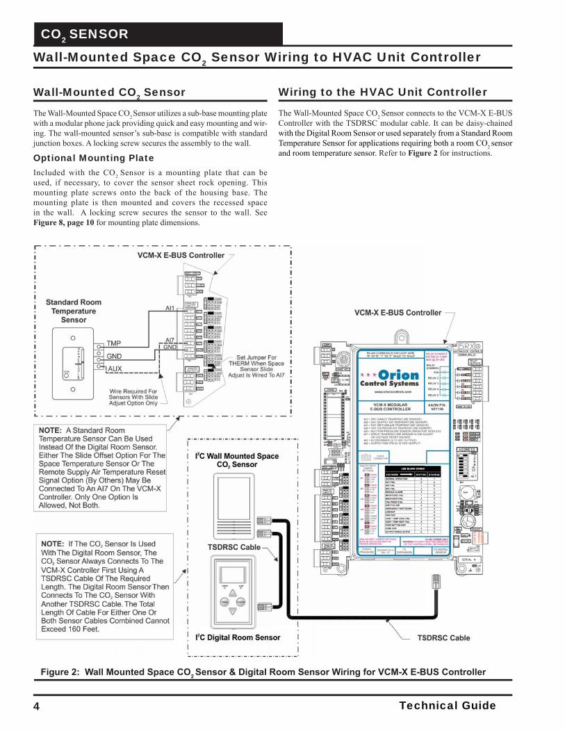
Figure 2: Wall Mounted Space CO2 Sensor & Digital Room Sensor Wiring for VCM-X E-BUS Controller
Wall-Mounted Space CO2 Sensor Wiring to HVAC Unit Controller
Wall-Mounted CO2 Sensor
The Wall-Mounted Space CO2 Sensor utilizes a sub-base mounting plate with a modular phone jack providing quick and easy mounting and wir-ing. The wall-mounted sensor’s sub-base is compatible with standard junction boxes. A locking screw secures the assembly to the wall.
Optional Mounting PlateIncluded with the CO2 Sensor is a mounting plate that can be used, if necessary, to cover the sensor sheet rock opening. This mounting plate screws onto the back of the housing base. The mounting plate is then mounted and covers the recessed space in the wall. A locking screw secures the sensor to the wall. See Figure 8, page 10 for mounting plate dimensions.
Wiring to the HVAC Unit Controller
The Wall-Mounted Space CO2 Sensor connects to the VCM-X E-BUS Controller with the TSDRSC modular cable. It can be daisy-chained with the Digital Room Sensor or used separately from a Standard Room Temperature Sensor for applications requiring both a room CO2 sensor and room temperature sensor. Refer to Figure 2 for instructions.
Technical Guide
CO2 SENSOR
5
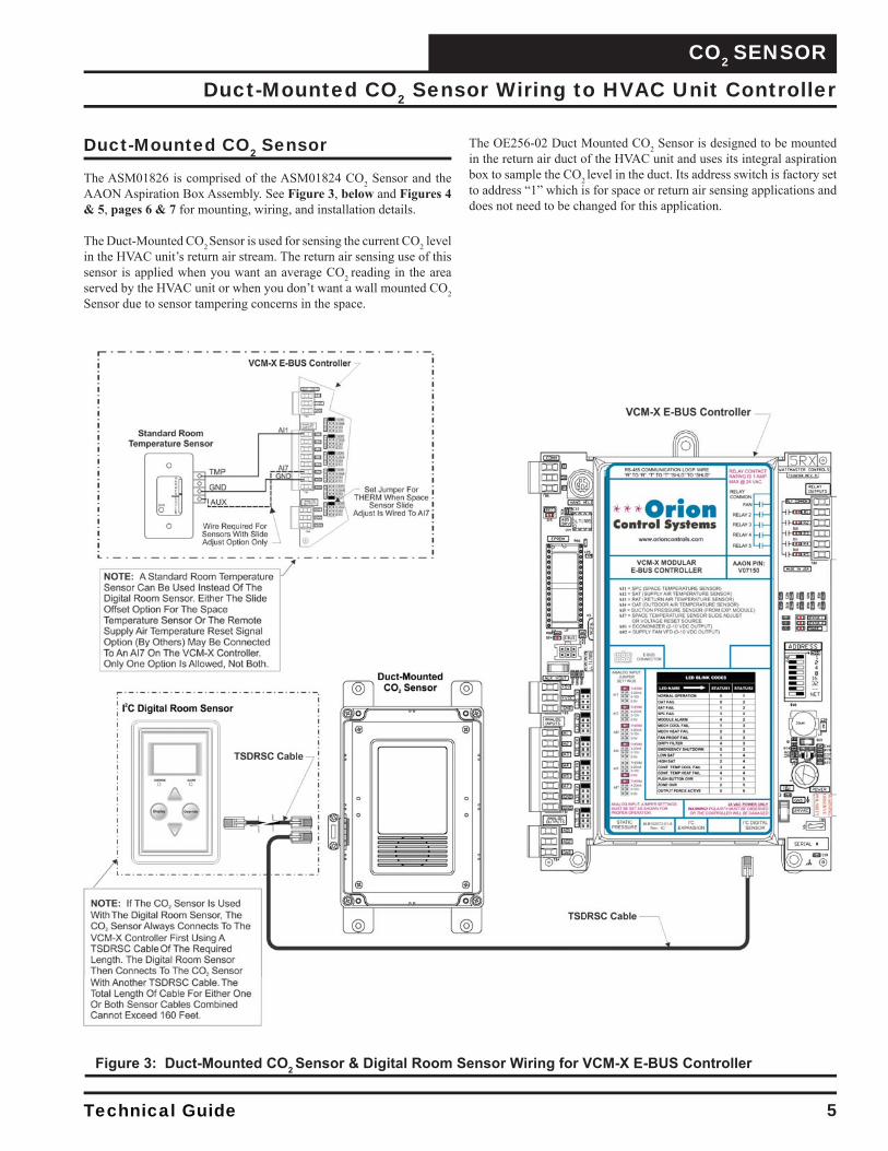
Figure 3: Duct-Mounted CO2 Sensor & Digital Room Sensor Wiring for VCM-X E-BUS Controller
Duct-Mounted CO2 Sensor Wiring to HVAC Unit Controller
Duct-Mounted CO2 Sensor
The ASM01826 is comprised of the ASM01824 CO2 Sensor and the AAON Aspiration Box Assembly. See Figure 3, below and Figures 4 & 5, pages 6 & 7 for mounting, wiring, and installation details.
The Duct-Mounted CO2 Sensor is used for sensing the current CO2 level in the HVAC unit’s return air stream. The return air sensing use of this sensor is applied when you want an average CO2 reading in the area served by the HVAC unit or when you don’t want a wall mounted CO2 Sensor due to sensor tampering concerns in the space.
The OE256-02 Duct Mounted CO2 Sensor is designed to be mounted in the return air duct of the HVAC unit and uses its integral aspiration box to sample the CO2 level in the duct. Its address switch is factory set to address “1” which is for space or return air sensing applications and does not need to be changed for this application.
CO2 SENSOR
Technical Guide 6
Duct-Mounted CO2 Sensor Installation
Duct-Mounted CO2 Sensor Installation
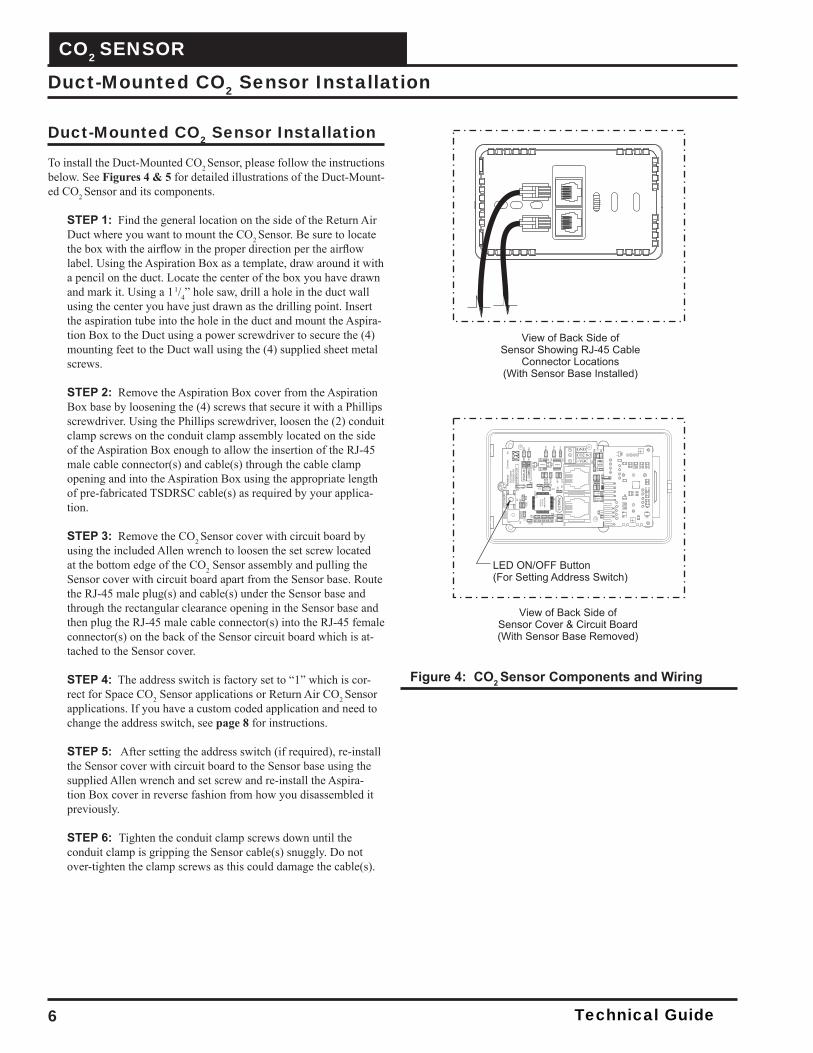
To install the Duct-Mounted CO2 Sensor, please follow the instructions below. See Figures 4 & 5 for detailed illustrations of the Duct-Mount-ed CO2 Sensor and its components.
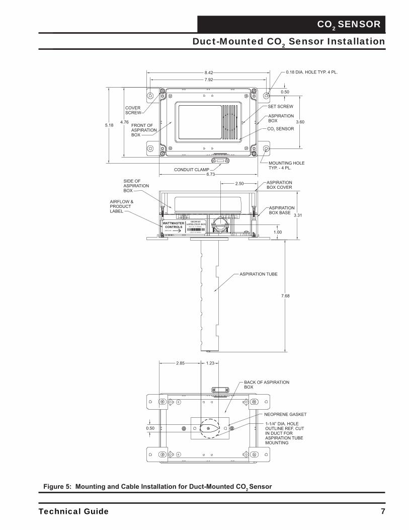
STEP 1: Find the general location on the side of the Return Air Duct where you want to mount the CO2 Sensor. Be sure to locate the box with the airfl ow in the proper direction per the airfl ow label. Using the Aspiration Box as a template, draw around it with a pencil on the duct. Locate the center of the box you have drawn and mark it. Using a 1
1/4” hole saw, drill a hole in the duct wall using the center you have just drawn as the drilling point. Insert the aspiration tube into the hole in the duct and mount the Aspira-tion Box to the Duct using a power screwdriver to secure the (4) mounting feet to the Duct wall using the (4) supplied sheet metal screws.
STEP 2: Remove the Aspiration Box cover from the Aspiration Box base by loosening the (4) screws that secure it with a Phillips screwdriver. Using the Phillips screwdriver, loosen the (2) conduit clamp screws on the conduit clamp assembly located on the side of the Aspiration Box enough to allow the insertion of the RJ-45 male cable connector(s) and cable(s) through the cable clamp opening and into the Aspiration Box using the appropriate length of pre-fabricated TSDRSC cable(s) as required by your applica-tion.
STEP 3: Remove the CO2 Sensor cover with circuit board by using the included Allen wrench to loosen the set screw located at the bottom edge of the CO2 Sensor assembly and pulling the Sensor cover with circuit board apart from the Sensor base. Route the RJ-45 male plug(s) and cable(s) under the Sensor base and through the rectangular clearance opening in the Sensor base and then plug the RJ-45 male cable connector(s) into the RJ-45 female connector(s) on the back of the Sensor circuit board which is at-tached to the Sensor cover.
STEP 4: The address switch is factory set to “1” which is cor-rect for Space CO2 Sensor applications or Return Air CO2 Sensor applications. If you have a custom coded application and need to change the address switch, see page 8 for instructions.
STEP 5: After setting the address switch (if required), re-install the Sensor cover with circuit board to the Sensor base using the supplied Allen wrench and set screw and re-install the Aspira-tion Box cover in reverse fashion from how you disassembled it previously.
STEP 6: Tighten the conduit clamp screws down until the conduit clamp is gripping the Sensor cable(s) snuggly. Do not over-tighten the clamp screws as this could damage the cable(s).
Figure 4: CO2 Sensor Components and Wiring
Technical Guide
CO2 SENSOR
7
Figure 5: Mounting and Cable Installation for Duct-Mounted CO2 Sensor
Duct-Mounted CO2 Sensor Installation
CO2 SENSOR
Technical Guide 8
Troubleshooting
Setting the Sensor Address Switch
LED ON/OFF Push-Button Operation for SettingAddressThe LED ON/OFF Push-Button is used to set the CO2 Sensor’s address. The LED ON/OFF Push-Button is located on the Sensor’s board and is only visible by removing the back cover. See location in Figure 6. The default addresses are as follows:
• Space or Return CO2 Sensor = Address 1 (Default)• Address 2 is reserved.• Open addresses for Custom Applications = Addresses 3-10
To set the address, follow these instructions:
1. Power up the VCM-X Controller that the Sensor is plugged into.
2. Press the LED ON/OFF Push-Button for 5 seconds until the LEDs turn off .
3. Then press the push-button the number of times that repre-sents the address. Press once for address 1, press twice for address 2, etc.
4. The address range can be set to 1 (default) and from 3 to 10.5. To verify that the correct address has been entered, refer to
the STATUS LED information below.
The board address is stored in nonvolatile memory. Once the address is set, the address will be saved after loss of power.
Using LEDs to Troubleshoot
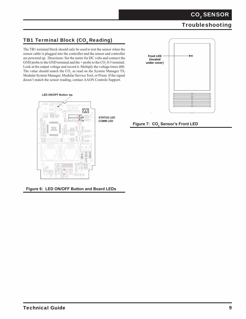
LEDs are available for troubleshooting the CO2 Sensor. The Front LED is visible through the front cover of the CO2 Sensor. See Figure 7 for location. The other LEDs are located on the Sensor’s board and are only visible by removing the back cover. See Figure 6 for locations.
LED ON/OFF Push-ButtonThis button is located on the CO2 Sensor’s board. See Figure 6. This button is initially set for “LEDs OFF.” Push this button to enable/disable the LEDs. Pushing this button ON will make the Front LED light up. This LED is also used for setting the address.
Front LEDWhen the LEDs are turned on, a green LED will be visible through the front plastic cover of the CO2 sensor. See Figure 7. The Front LED will blink whenever a CO2 sample is taken. A sample is taken every 30 seconds.
STATUS LEDInitially, the STATUS LED blinks fast for 30 seconds. It then stays on and blinks the board address whenever a CO2 sample is taken. A CO2 sample is taken once every 30 seconds.
COMM LEDThe COMM LED blinks on whenever communications are sensed.
Altitude Correction
Altitude correction can be confi gured using one of our operator inter-faces. The altitude can be confi gured at a value of 0-15,000 feet. The default is 500 feet.
Technical Guide
CO2 SENSOR
9
Figure 6: LED ON/OFF Button and Board LEDs
Figure 7: CO2 Sensor’s Front LED
TB1 Terminal Block (CO2 Reading)
The TB1 terminal block should only be used to test the sensor when the sensor cable is plugged into the controller and the sensor and controller are powered up. Directions: Set the meter for DC volts and connect the GND probe to the GND terminal and the + probe to the CO2 0-5 terminal. Look at the output voltage and record it. Multiply the voltage times 400. The value should match the CO2 as read on the System Manager TS, Modular System Manager, Modular Service Tool, or Prism. If the signal doesn’t match the sensor reading, contact AAON Controls Support.
Troubleshooting
CO2 SENSOR
Technical Guide 10
Appendix - Mounting Plate Dimensions
Optional Mounting Plate
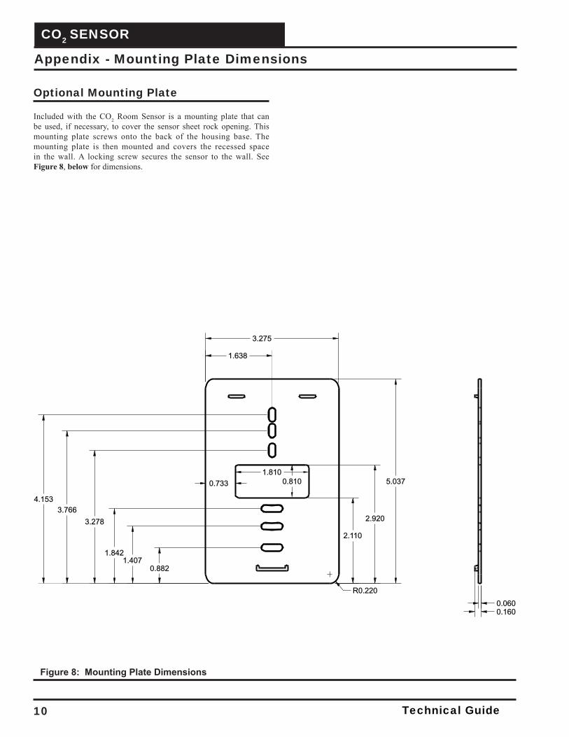
Included with the CO2 Room Sensor is a mounting plate that can be used, if necessary, to cover the sensor sheet rock opening. This mounting plate screws onto the back of the housing base. The mounting plate is then mounted and covers the recessed space in the wall. A locking screw secures the sensor to the wall. See Figure 8, below for dimensions.
1.638
1.810
0.882
1.407
1.842
0.733
2.110
2.920
0.810
R0.220
3.275
0.060
0.160
5.037
3.278
3.766
4.153
Figure 8: Mounting Plate Dimensions

Technical Guide
CO2 SENSOR
11
Notes

2425 South Yukon Ave • Tulsa, OK • 74107-2728Ph: (918) 583-2266 • Fax: (918) 583-6094
AAON P/N: G042470, Rev. 01F Printed in the USA • © August 2019 AAON, Inc. • All Rights Reserved
AAON Factory Technical Support: [email protected]
AAON Controls Support: 866-918-1100Monday through Friday, 7:00 AM to 5:00 PM
central standard time.
NOTE: Before calling Technical Support, please have the model and serial number of the unit available.
PARTS: For replacement parts please contact your local AAON Representative.


![LTR-507ALS-01 Product Data Sheet Optical Sensor€¦ · The LTR -507ALS -01 is an integrated I2C digital light sensor [ALS] and proximity sensor [PS] with built -in LED driver, in](https://img.pdfslide.us/doc/110x75/605326a1a1e132235a2c6e14/ltr-507als-01-product-data-sheet-optical-sensor-the-ltr-507als-01-is-an-integrated.jpg)