Embed Size (px)
Citation preview

MAS
ONRY
TOTIMBE
RWAL
LTIES
WAL
LST
ARTE
RSY
STEM
SOT
HERMAS
ONRY
PROD
UCTS
MAS
ONRY
TOMAS
ONRY
WAL
LTIES
WAR
MRO
OFNA
ILS
Wall Ties &Restraint Fixings
MAS
ONRY
TOST
EEL
WAL
LTIES
TECH
NICA
LINFO
RMAT
ION
Now includes
MASONRY
REINFORCEMENT

Stainless SteelAll Ancon and Staifix wall ties are manufacturedfrom Stainless Steel for its corrosion resistanceand strength. The use of Stainless Steel meansthat no costly remedial measures are requiredduring the lifetime of the structure.
ApprovalsLook for these logos.
These products are approved by theBritish Board of Agrément.
These products meet the technicalrequirements of the National House BuildingCouncil.
These products are Type A ties and suitablefor internal separating walls to ApprovedDocument E.
AvailabilityAncon and Staifix wall ties are available frombuilders merchants throughout the UK.For details of your nearest stockist pleasecontact Ancon on 0114 238 1 238.
SafetyAll Ancon and Staifix wall ties have speciallydesigned safety ends to reduce the risk ofinjury during handling and installation.
Correct InstallationWall ties should be pressed down in, and thensurrounded by, fresh mortar. In order to showmore details of the application, mortar hasbeen excluded from the photography in thisliterature.

MAS
ONRY
TOTIMBE
RWAL
LTIES
WAL
LST
ARTE
RSY
STEM
SOT
HERMAS
ONRY
PROD
UCTS
MAS
ONRY
TOMAS
ONRY
WAL
LTIES
WAR
MRO
OFNA
ILS
MAS
ONRY
TOST
EEL
WAL
LTIES
Masonry to Masonry Wall Ties Pages 8-13Staifix HRT4 Light Duty TieStaifix RT2 General Purpose TieAncon ST1 Heavy Duty TieOther Standard & Bespoke Ancon Wall TiesStaifix-Thor Helical TJ2 Thin-Joint Tie
Wall Starter Systems Pages 14-17Staifix Universal Wall Starter SystemStaifix Starter TieStaifix Cavity Starter Tie
Masonry to Timber Wall Ties Pages 18-21Staifix Timber Frame TieStaifix Frame Tie
Masonry to Steel Wall Ties Pages 22-23Ancon 25/14 Restraint System
Other Masonry Products Pages 24-29Ancon AMR Masonry ReinforcementAncon HiT (Hammer-in Tie)Staifix-Thor Helical Crack Stitching Kit
Technical Information Pages 4-7Installation GuidanceWall Tie SelectionTie Length & EmbedmentDensity & Positioning of Ties
Warm Roof Nails Pages 30-31Super-7 Thor-Helical Nail for Pitched RoofsSuper-8 Headed Helical Nail for Flat Roofs
TECH
NICA
LINFO
RMAT
ION

4
Wall ties are an important element inthe stability of cavity walls. The correctselection, spacing and installation of tiesis essential to avoid damp penetrationand the distortion or cracking ofbrickwork.
Staifix wall ties are manufactured fromcorrosion-resistant stainless steel. Theyfeature safety ends to reduce the risk ofinjury and multiple drips to preventmoisture crossing the cavity. Staifix HRT4and RT2 wall ties replace Butterfly andDouble Triangle wall ties respectively.
BS1243, the British Standard forButterfly and Double Triangle WallTies, was withdrawn in January 2005.
Cavity Wall Tiesfor traditional brick/block construction

5
TECH
NICA
LINFO
RMAT
ION
Wall Tie InstallationWall ties should be pressed downin, and then surrounded by, freshmortar.
To ensure cavity wall ties areeffective at tying the leavestogether they should be installedas the inner leaf is constructedand not simply pushed into a joint.
Ties should be installed with aslight fall to the outer leaf, nevertowards the inner leaf as this couldprovide a path for moisture tocross the cavity.
The drip part of the tie shouldpoint downwards and bepositioned near the centre of theopen cavity. Ties with multipledrips, like the Staifix RT2, canoften be positioned centrally aspart of the drip will normally benear the centre of the opensection of a partial fill cavity.Installed ties should be clear ofmortar droppings to allow the dripto function and prevent water fromcrossing to the inner leaf ofmasonry.
SD1 Flat Tie
MaximumBuilding Geographical
Wall Tie Type Application Density Height Location
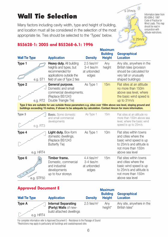
Type A 2.5 ties/m2 Anyheight*
≤ 25m/s
≤ 31m/s
MaximumBuilding Geographical
Wall Tie Type Application Density Height Location
Type 1 2.5 ties/m2 Any3-4 ties/m heightat unbondededges
Type 2 As Type 1 15m
Type 2 ties are suitable for use outside these parameters e.g. sites over 150m above sea level, sloping ground andbuildings exceeding 15 metres, if shown to be adequate by calculation. Contact Ancon for more information.
Type 3 As Type 1 15m
Type 4 As Type 1 10m
Type 6 4.4 ties/m2 15m3-4 ties/mat unbondededges
6
Information taken fromBS 6399-2: 1997Code of Practice forWind Loads. This mapshould be read inconjunction withaltitude restrictions.
Wall Tie SelectionMany factors including cavity width, type and height of building,and location must all be considered in the selection of the mostappropriate tie. Ties should be selected to the ‘Types’ below.
Heavy duty. All buildingheights and types, butrecommended forapplications outside thefield of use of Type 2 tiesGeneral purpose.Domestic and smallcommercial developments.(Replace BS1243Double Triangle Tie)
Basic. Some domesticand small commercialdevelopments
Light duty. Box-formdomestic dwellings.(Replace BS1243Butterfly Tie)
Timber frame.Domestic, commercialand industrialdevelopmentsup to four storeys
Internal Separating(Party) Walls of new-build attached dwellings
Any site, anywhere in theBritish Isles (provisionshould be calculated forvery tall or unusuallyshaped buildings)Flat sites at an altitudeno more than 150mabove sea level, wherethe basic wind speed isup to 31m/s
Flat sites at an altitude nomore than 150m above sealevel, where the basic windspeed is up to 25m/s
Any site, anywhere in theBritish Isles*
For complete information refer to Approved Document E - Resistance to the Passage of Sound*Restrictions may apply to particularly tall buildings and coastal/exposed sites
Flat sites within townsand cities where thebasic wind speed is upto 25m/s and altitude isnot more than 150mabove sea level
Flat sites within townsand cities where thebasic wind speed is upto 25m/s and altitude isnot more than 150mabove sea level
BS5628-1: 2005 and BS5268-6.1: 1996
Approved Document E
e.g. ST1
e.g. RT2
e.g. HRT4
e.g. HRT4
e.g. STF50
e.g. RT3

7
Ancon recommends tie lengths which achievean embedment of between 62.5mm and 75mm.A tie, 225mm long, would be the minimumlength recommended for a 100mm cavity.62.5mm + 100mm + 62.5mm = 225mmThe embedment depths for Staifix-Thor Helicalthin-joint ties differ from the information aboveand are shown on page 13.
Tie Length & Embedment
Embedment
Insulation retaining clip
Embedment
Multiple drips
Cavity width
Density and Positioning of TiesTypical Layout of Wall Ties Indicating Maximum SpacingStandard spacing for cavity brickwork 900mm x 450mm centres in a staggered pattern(2.5 ties per m2). This spacing may be varied by building regulations.
225mm
225mm
225mm
225mm
900mm
450mm
450mm
300mm 300mm
Horizontal movement joint 450-900mm
Usually 225mmto suit blockcourses
Usually 225mmto suit blockcourses
225mm
Verticalmovementjoint
450mm
225mm
450mm
Debondedties atedges
Head restraintsat centres tosuit windloading
TECH
NICA
LINFO
RMAT
ION
Ties should be evenly distributed over the wall area, except around openings, and should bepreferably staggered.Note: At vertical edges of an opening, unreturned or unbonded edges, and vertical expansion joints, additional ties should be used. Such ties should be located at300mm vertical centres, positioned not more than 225mm from the edge.

Length (mm) Cavity (mm)
200 50-75225 76-100250 101-125
ApplicationType 4 wall tie for use in the external walls ofhouses up to 10 metres in height. Altitudeand wind speed restrictions may apply, referto page 6 for more details.Type A tie suitable for internal separatingwalls of buildings of any height with a50-100mm and 125mm cavity.
�
�
�
�
Staifix RT2 General Purpose Tie (Type 2 Tie)
Staifix HRT4 Light Duty Tie (Type 4/Type A Tie)
Length (mm) Cavity (mm)
200* 50-75225* 76-100250 101-125
8
ApplicationType 2 wall tie for use in the external walls ofhouses and small commercial developmentsup to 15 metres in height. Altitude and windspeed restrictions may apply, refer to page 6for more details. This tie is unsuitable forinternal separating walls of new buildattached dwellings.RT3 Type 3 ties are also available, see page 10.
Patent Nos. GB 2359831IE 83574
Patent Nos. GB 2359831IE 83574
REPLACES BS1243
BUTTERFLY TIE
REPLACES BS1243
DOUBLE TRIANGLE TIE
*
Available in bags of 20 and boxes of 250
Available in bags of 20 and boxes of 250

ApplicationType 1 wall tie for use in the external wallsof buildings of any height anywhere in theBritish Isles. This tie is unsuitable forinternal separating walls of new buildattached dwellings. Refer to page 6 formore details.
ApplicationInsulation retaining clip for use in partial fillcavities with all* standard Ancon and Staifixwall ties.*The TJ Clip should be used with Staifix-Thor Helical TJ2 ties.
Ancon ST1 Heavy Duty Tie (Type 1 Tie)
Staifix Universal Insulation Retaining Clip
9
Length (mm) Cavity (mm)
200 50-75225 76-100250 101-125275 126-150300 150*
�
AnconWire Ties
AnconST1
AnconFlat Ties
UK Patent Nos. 2 255 3582 260 3482 260 349
REPLACES BS1243
VERTICAL-TWIST TIE
�
MAS
ONRY
TOMAS
ONRY
WAL
LTIES
*With greater embedment to simplify installation
Available in boxes of 250
Available in bags of 20 and 250

10
DT Double TriangleLengths 150*, 200*, 225*,250 **, 300mm***Conforms to BS5628-1 asa Type 2 tie**Type 3 tie
ACO1 ButterflyLengths 200*, 225, 250mm*Conformed to BS 1243(withdrawn in 2005) andsuitable for party walls.Ancon recommends use ofthe HRT4 tie (page 8)
SD1Lengths 200, 225, 250, 275,300mmConforms to BS5628-1 as aType 1 tie. Also available witha central drip
SDBLengths 125, 150, 175, 200,225mm
SDVLengths 125, 150, 175, 200,225mm
SD21Lengths 125, 150, 175, 200,225mmFor use with 21/18Omega Channel
SRBLengths 125, 150, 175,200mm
Other Standard Ancon Wall Tieslengths shown in red italics refer to items available within 24 hours
90mm
90mm
90mm
ApplicationSafety-ended frame cramp used to joinmasonry to concrete or steel frames.
CAN BE USED
WITH A DEBONDING
SLEEVE
30mm
7mmdiameterhole
L
L
ApplicationFlat tie used with a debonding sleeve toallow the masonry to expand or contract.
10mm Gap
Ancon SPB Frame Cramp Ancon PPS Movement Tie
Lengths 75, 100, 125, 150, 175, 200mm Lengths 225, 250mm
FOR VERTICAL
MOVEMENT JOINTS
SPSLengths 150, 200, 225, 250,275, 300mm
SPS CJLengths 150mm(3mm thickness forcollar-jointed construction)
RT3Lengths 200, 225, 250mmConforms to BS5628-1 asa Type 3 tie
90mm
WHXLengths 150, 175, 200mm
*
L

11
MAS
ONRY
TOMAS
ONRY
WAL
LTIES
TAILMost can be usedat either end of tie
SHANK
L _ _
S _ _
_ D _
_ P _
_ V _
_ F _
_ H _
P _ _
D _ _
Y _ _
M_ _
W _ _
T _ _
260mm
25mm
10mm 6x60mm loosedowel
6x60mm loosedowel
6x60mm weldeddowel
L
L
10mm
10mm
10
20
50
30
10
10
8x30mm slot
7mm diameterhole
L
L
10mm
To fit 21/18Omega Channel
_ _ 25 To fit 25/14_ _ 28 To fit 28/15_ _ 30 To fit 30/20_ _ 36 To fit 36/8_ _ 38* To fit 38/17*Tie will be 25mm wide
7mm diameterhole
105mm
_ _ V_ _ U without slot
_ _ B
_ _ 21
_ _ X
_ _ G
30
6.5mmdiameter holes
15mm15mm
References for Bespoke Ancon Wall TiesAncon wall ties may be specified andordered by using a reference letter forthe tail, shank and head of the tie.
Example usingReference System
Shank P
Tail D Ancon DP21wall tie
Head 21
Ancon Remedial Wall Ties
HAVE A
QUESTION? CALL
0114 238 1 238
To suit channel
AC31Lengths 175, 200, 225mm
MM63Lengths 195, 220, 250,300mm
AC31CLengths 175, 200, 225mm
RM63Lengths 195, 220, 250,300mm
Setting tools, resin cartridges, resin guns and mixing nozzlesare all available. Contact Ancon for more details on our rangeof remedial wall ties and ancillary products.
HEAD

12
Staifix-Thor Helical TJ2 Tie
ApplicationHammer-driven cavity wall tie, ideal forthin-joint blockwork and other applicationswhere the joints of the inner and outerleaves of masonry do not course.
For thin-joint to thin-joint separating wallsuse the Staifix HRT4 (see page 8).
European Patent No. 1307303
for thin-joint blockwork
Length (mm) Cavity (mm)
205 50230 75255 100280 125305 150
Block Strength Tie Type to BS 5628-1N/mm2 ≤ 100mm Cavity 125mm Cavity
2.8 4 4
3.5 - 4.0 3 4
7.0 - 10.5 2 3
HAMMERS
DIRECTLY INTO
AIRCRETE BLOCKS
Notes: Reference should be made to the information on page 6 formaximum building height and restrictions based on geographicallocation.

Support tools are available to simplify installation.
Build into the bed joint of the outerleaf ensuring the tie is surroundedby mortar.
Install a black Staifix TJ InsulationRetaining Clip to restrain theinsulation.
Hammer the tie, through theinsulation, and into the blockworkto the correct embedment.
Keep the brickwork one courseclear during installation of the ties.Position the tie against the innerleaf so that the outer end will belocated in the bed joint of theexternal leaf.
Installation
1
3
4
85mm 70mm
Embedment
Staifix-Thor Helical TJ2 Thin-Joint Ties should have a minimum embedment of85mm in the inner leaf of blockwork and 70mm in the outer leaf of brickwork.
2
13
MAS
ONRY
TOMAS
ONRY
WAL
LTIES

14
Staifix Universal Wall Starter Systemfor joining new walls to existing masonry
ApplicationWall starter system with all the necessaryfixings (ties, plugs and screws) to join asingle skin of masonry 2.4 metres high toan existing wall.
Ideal for the construction of conservatories,extensions and garden walls.
Insert
Turn
Slide
CHANCE TO WIN £500
WITH EACH PACK

450/600mm
==
225mm
=600/450mm
450/600mm
600/450mm
1 3
Overlap
Loosely fix first strip at thebottom two fixing points.Insert second strip into thetop of the first strip andloosely fix at the remainingthree fixing points. Fullytighten screws, in anyorder, when both strips arein position.
Insert wall ties as shownand build into the bedjoints of the new wallensuring they aresurrounded by mortar.Repeat up to a maximumheight of 8 metres.
This wall starter will resist a wind load of up to 4.5kN over a height of 2400mm.Prior to installation remove any render, debris etc from the existing wall in the area wherethe new wall will be joined.
Installation
Mark the position of thefive fixing holes so that thewall starter system iscentral to the new wall.When overlapped, thestrips should be fixedthrough the first and lastslot, at the point of overlapand at two other points inbetween. Drill 10mmdiameter holes and installplugs.
2
WAL
LST
ARTE
RSY
STEM
S
15
WAL
LST
ARTE
RSY
STEM
S

16
Staifix Starter Tiefor joining new walls to existing masonry
ApplicationScrew-in tie supplied with an 8mm nylonplug for joining new masonry to existingwalls without the need for jointing.
Ideal for the construction of conservatories,extensions and garden walls.
AVAILABLE
SINGULARLY - NO
JOB TOO SMALL

Drill an 8mm diameter holehorizontally into existing outer leaf ofmasonry. Position the hole such thatwhen the tie is installed the safetyend will be located in the bed joint ofthe new inner leaf of blockwork.
Insert the nylon plug. Slide theneoprene ‘o’ ring on the tie andscrew into the plug. Build the tie intothe inner leaf of blockwork ensuring itis surrounded by mortar.
Staifix Cavity Starter Tie Installation
Staifix Cavity Starter Tie
Starter Ties should be fixed at225mm vertical centres in a linecentral to the new leaf. Drill 8mmdiameter holes, 45mm deep intothe existing wall at an angle of 30˚to the horizontal.
Bend the tie into the bed jointof the new brickwork. Build the tiein ensuring it is surrounded by mortar.
for the build of a new inner leaf of blockwork
Staifix Starter Tie Installation
ApplicationScrew-in tie that simplifies the build of an inner leaf of blockwork withinan existing structure. Supplied with an 8mm nylon plug and a neoprene‘o’ ring.
This tie is suitable for use in masonry up to 8 metres in height. For buildings in particularly exposed areas,especially if the wall is higher than 5 metres or the construction is single leaf, it would be advisable to carryout a check calculation using the wind code and increase the density of starter ties if necessary.
1
2
IDEAL FOR BARN
CONVERSIONS
17
WAL
LST
ARTE
RSY
STEM
SWAL
LST
ARTE
RSY
STEM
S

Staifix Timber Frame Tiefor fixing masonry to timber frames
ApplicationCavity wall tie for use in theconstruction of timber-framed buildingsup to 4 storeys in height. Suppliedcomplete with an annular ring shanknail.
To Suit Cavities (mm)
50, 75, 100
CRANKED, TO
EASE INSTALLATION
18

Installation
Build the tie into the bed joint of thenew masonry ensuring it issurrounded by mortar.
Hammer the nail, through the holein the upstand, into the timberframework.
Position the tie on fresh mortar in thebed joint of the outer leaf of masonrywith the upstand against the timber.
1
2
3
Density of Timber Frame Ties
Timber Frame Ties should be installed at a density of 4.4 ties persquare metre in buildings where the basic wind speed does notexceed 25m/s (BS6399-2: 1997 Code of Practice for Wind Loads).The density should be increased to 7 ties per square metre in moresevere situations.
MAS
ONRY
TOTIMBE
RWAL
LTIES
19

ApplicationScrew-in tie used to join timber door andwindow frames to brickwork.
Staifix Frame Tiefor fixing timber door and window frames to brickwork
NO PILOT
HOLE REQUIRED
20

Maximum vertical spacing of Staifix Frame Ties for most buildingsin the UK* with a maximum brickwork height of 15 metres
Main Front and Rear Elevations with most Windows
Max. Vertical Tie Spacings for Various Frame Widths (mm)900 1200 1500 1800 2100 2400 2700 3000
Towns and Cities 450 450 300 300 225 225 150 150
Open Country 450 375 300 225 225 150 150 150
Side Elevations with few Windows
Max. Vertical Tie Spacings for Various Frame Widths (mm)900 1200 1500 1800 2100 2400 2700 3000
Towns and Cities 450 300 225 225 150 150 150 75
Open Country 375 225 225 150 150 75 75 75
Note: The area of doors and windows in the wall is more than half the area of doors and windows in the other walls.
The Staifix Frame Tie should not be used as a wall starter tie (see page 16).
Note: The area of doors and windows in the wall is less than half the area of doors and windows in the other walls.
*Excludes the Scottish Highlands, Western Ireland and buildings on slopes greater than 1 in 20.Please contact Ancon Building Products for applications outside the tables above.
Installation
Screw the tie horizontally into thedoor or window frame at a bedjoint position.
Build the tie into the bed joint of thenew brickwork ensuring that it issurrounded by mortar.
1
2
21
MAS
ONRY
TOTIMBE
RWAL
LTIES

Ancon 25/14 Restraint Systemfor tying masonry to steel frames
ApplicationChannel and cavity wall tie for use in theconstruction of steel-framed buildings.Self-drilling screws fix through the channeland the insulation material, into the steel.
Tie Length (mm) Open Cavity (mm)
100 50
SUITABLE FOR
BUILDINGS UP TO
40M HIGH
22
Note: Other tie lengths are available.

Build the tie into the bed joint of the newmasonry ensuring it is surrounded bymortar.
The spacing of ties is based on the heightof the building and geographical location.See the table below and the map onpage 6 for recommended spacing. SD25wall ties can be positioned at any pointalong the channel’s length. Ties shouldachieve a minimum embedment of62.5mm in the outer leaf and be presseddown in fresh mortar.
Ancon 25/14 channel is supplied withpre-punched holes at 112.5mm centres.This ensures a fixing position is alwayslocated near the end when the channel iscut on site. Using self-drilling screws thechannel should be fixed at 450mmvertical centres (every fourth hole).
Installation
1
2
3
23
Note: Screws are available in various lengths to accommodate an insulation thickness of up to 95mm. Ancon recommends theuse of stainless steel fixing screws.
Tie Spacing Based on 25/14 Channel at 600mm Horizontal Centreswith Basic Wind Speed < 25m/s
Altitude and Distance Vertical Tie Spacing (mm) for Various Heights of Brickworkfrom the Coast 15m 25m 40mAltitude up to 150m and atleast 50km from the coast 450 225 225
Altitude up to 25m andwithin 50km from the coast 450 300 225
Note: Wind zones are taken from BS6399-2: 1997 Code of Practice for Wind Loads. See page 6.
MAS
ONRY
TOST
EEL
WAL
LTIES

24
Ancon AMR Masonry Reinforcementto strengthen masonry panels
ApplicationStainless or galvanised steel reinforcement,installed in a bed joint to strengthenmasonry walls. Manufactured in lengthsof 2700mm.
Available in five wire diameters and fourwidths, AMR suits the majority of wallconditions.
FLATTENED TO ENSURE
GOOD MORTAR COVER
AMR Width Wall Thickness
60mm 100-125mm Brick/Block100mm 140-150mm Block150mm 190-200mm Block175mm 215mm Block

25
Laps and PositioningThe position of laps should be staggered throughout the masonry panel.
Laps should be a minimum of 225mm in length and can be achieved by eitherstacking the product or positioning lengths side by side.
CornersPrefabricated corner units can be manufactured to provide true continuity ofreinforcement. Alternatively, Ancon AMR can be cut and bent on site.
min. 225mm
min. 225mm
Positionedside by side
Stacked
Notes: Overall thickness when stacked is less than 6mm.
OTHE
RMAS
ONRY
PROD
UCTS

26
Ancon HiT (Type 2 Tie)Hammer-in Tie for multiple cavity widths
ApplicationHammer-in Tie for fixing masonry toconcrete, dense blocks (≥7N/mm2),non-perforated brick or hard stone.This tie is hammered into a plug andbent to suit the size of cavity.
Length (mm) Cavity (mm)
310 up to 150
SUITS MULTIPLE
CAVITY WIDTHS
Note: A special installation tool is required.

27
Remove the tool and build the tie intothe bed joint of the outer leaf.
Supporting the tie by hand in the opencavity, bend parallel to the brickwork,ensuring an angle of 85-90° isachieved.
Re-insert the tie in the tool leavingenough tie exposed to allow foradequate embedment in the outer leaf.Ancon recommends an embedmentdepth of between 50-65mm.
Hammer the tool until the tie is nolonger visible. Remove the tool andpush the ‘O’ ring on to the tie to acentral position in the open cavity.
Insert the plain end of the tie into thetool, as far as it reaches leaving the45mm thread exposed. Locate the tiein the plug.
Drill a 6mm diameter hole 50mm deepand insert the nylon plug.
Installation
1
2
3
4
5
6
Notes: The Ancon HiT is not suitable for use with low density materials.Must be used with plug supplied.
50-65mm Embedment depth
Cross section view
85-90°
Plan view
Cross section view
OTHE
RMAS
ONRY
PROD
UCTS

28
Staifix-Thor Helical Crack Stitching Kitfor the permanent repair of cracked masonry
ApplicationThis kit contains all the necessarycomponents to permanently repair verticalor stepped cracks in masonry.
• Grout mixing paddle
• Cementitious grout (3 litres)
• Grout applicator gun
• Flat grout nozzle
• Stainless steel helical bar (10 x 1000mm)
• Finger trowel
Notes:1. This system is also suitable for rendered/plastered walls2. Vertical spacing is normally every 4 to 6 brick courses
(300 - 450mm), however this should be checked with thestructural engineer
3. Where cracks are within 500mm of corners or reveals, the barshould be bent and bonded 100mm around the corner
4. If two or more cracks are close together, bars can be lapped.Laps should be at least 500mm and the bar should extend500mm from the outer cracks
Wall Slot BarThickness Depth Depth
102mm 30mm 20mm215mm 40mm 30mm
500mm 500mm
500mm 500mm
THE HIGH STRENGTH,
NON-DISRUPTIVE REPAIR
SOLUTION

29
InstallationIt is essential that the cause of the cracking is established by a structural engineerand then eliminated, prior to the installation of this system.
1
2
3
4
5
Cut a slot in the mortar joint to the specifieddepth that extends just over 500mm eachside of the crack (recommended equipment:Twin-bladed diamond-tipped wall chaser).Ensure the mortar is completely removedto reveal the top and bottom faces of themasonry. Remove all loose mortar from theslot and flush with clean water.
Make good the bed joint and fill thevertical crack with an appropriate filleror mortar.
Apply a second, continuous bead ofgrout to the slot, ensuring the bar iscovered. With the finger trowel, forcethe grout back into the slot 10mm fromthe surface, and ensure the bar/groutcomposite is tightly packed.
Push the helical bar into the face of thegrout, to the depth specified, so thatthe bar extends 500mm each side ofthe crack.
Connect the paddle to a power drill,blend the components of the grouttogether in the tub and load into the gun.Apply a continuous bead (approximately10-15mm thick) to the back of the slotusing the flat grout nozzle.
OTHE
RMAS
ONRY
PROD
UCTS

Helical Nails for Warm Roof Construction
Pitched Roofs
Helical nails fix counterbattens to rafters, without compressing the layer of insulationin-between.
Headed helical nails fix plywood/insulation composite roof panels to joists.
Flat Roofs
Min.35mm
Min.35mm
30

Product Range
Super-7™ Thor-Helical Nailfor Pitched RoofsStocked Lengths:140, 150, 160, 165, 175, 185mmNote: Other lengths are available in increments of 5mm
Patent pending
Super-7™ Alignment Toolfor Pitched Roofs
Super-8 Headed Helical Nailfor Flat Roofs
Standard Lengths:135, 165, 195mmNote: Other lengths are available on request
European Patent No. 1307303
31
WAR
MRO
OFNA
ILS
HeliCalc CalculatorHeliCalc is a free web-based program which calculates the length,density and quantity of Super-7 nails required for a specific project.Visit www.helicalc.co.uk or contact Ancon for more information.
Helical nails are a quick and reliable fixing for use in warm roof applications. Unliketraditional nails, they rotate as they are driven in, inducing a self-tapping action andconsequently do not split or bounce timbers.
For more information on the above products please referto the ‘Helical Nails for Warm Roof Construction’ brochure

Ancon Building ProductsPresident Way, President Park, Sheffield S4 7URTel: +44 (0) 114 238 1 238Fax: +44 (0) 114 276 8543
Email: [email protected]: www.ancon.co.uk© Ancon Building Products 2009
Your local stockist is:
Ancon will advise on the correct selection of fixing to suit any projectand provide details of your nearest stockist.
Tel: 0114 238 1 238International Tel: +44 114 238 1 238
Visit: www.ancon.co.uk
The construction applications and details provided in this literatureare indicative only. In every case, project working details should beentrusted to appropriately qualified and experienced persons.
Whilst every care has been exercised in the preparation of thisdocument to ensure that any advice, recommendations orinformation is accurate, no liability or responsibility of any kind isaccepted in respect of Ancon Building Products.
With a policy of continuous product development Ancon BuildingProducts reserves the right to modify product design andspecification without due notice.
ISO 9001: 2008FM 12226
ISO 14001: 2004EMS 505377
This brochure is printed on paper produced from 80%recycled post-consumer fibre and 20% virgin pulp which issourced from responsibly managed and sustainable forests(FSC certified). The printing inks and sealant are vegetable-based making the document fully recyclable.


![Yl 2] ]Å^ tadt£t - indianrailways.gov.in · Yl 2] ]Å^ _tadt£t e ,WHP 1R 3DUWLFXODUV m w £ y 6DQFWLRQHG &RVW | E w § g e w Þ](https://img.pdfslide.us/doc/110x75/5d13a14488c99317298bd560/yl-2-a-tadtt-yl-2-a-tadtt-e-whp-1r-3duwlfxoduv-m-w-y-6dqfwlrqhg.jpg)