Embed Size (px)
Citation preview
NASA-TM-80704 19800019413
N/ A
i TechnicalMemorandum 80704
Meteorological Satellites- ,LIBRARYcOPY-
._, : 3'JMm
..... HAMPTON,VA
L. J. Allison (Editor), A. Schnapf, B. C. Diesen, III,P. S. Martin, A. Schwalb, and W. R. Bandeen
JUNE 1980
NationalAeronauticsandS0aceAdministration
GoddardSpaceFlightCenterGreenbelt.Maryland20771
https://ntrs.nasa.gov/search.jsp?R=19800019413 2018-06-17T19:33:57+00:00Z

METEOROLOGICALSATELLITES
LewisJ. Allison (Editor)
Goddard Space Flight Center
Greenbelt, Maryland
Contributing Authors: Abraham Schnapf, Bernard C. Diesen, III,
Philip S. Martin, Arthur Schwalb, and WilliamR. Bandeen
ABSTRACT
This paper presents an overviewof the meteorologicalsatellite programs that
havebeen evolvingfrom 1958 to the present and reviews plans for the future
meteorological and environmental satellite systems that are scheduled to be placed
into servicein the early 1980's. The development of the TIROS family of weather
satellites, including TIROS, ESSA, ITOS/NOAA,and the present TIROS-N (the
third-generation operational system) is summarized. The contribution of the
Nimbus and ATS technology satellites to the development of the operational polar-
orbiting and geostationary satellites is discussed. Included are descriptions of both
the TIROS-N and the DMSPpayloadscurrently under development to assurea
continued and orderly growth of these systemsinto the 1980's.
iii

CONTENTS
ABSTRACT ............................................... iii
EVOLUTION OF THE U.S. METEOROLOGICAL SATELLITE PROGRAMS ....... 1
TIROS ............................................... 1
ESSA ................................................ 1
ITOS ................................................ 3
TIROS-N .............................................. 4
NIMBUS ............................................... 5
ATS, APPLICATIONS TECHNOLOGY SATELLITE .................... 7
SMS/GOES (OPERATIONAL GEOSTATIONARY SATELLITE) ............. 8
TIROS-N SPACECRAFT SYSTEM ................................. 9
TIROS-N INSTRUMENTS ................................... 10
DATA COLLECTION SYSTEM (DCS) ............................ 16
SPACE ENVIRONMENT MONITOR (SEM) ......................... 18
THE EARTH RADIATION BUDGET EXPERIMENT (ERBE) .................. 20
VISIBLE INFRARED SPIN-SCAN RADIOMETER ATMOSPHERIC SOUNDER (VAS) . . 22
THE DEFENSE METEOROLOGICAL SATELLITE PROGRAM (DMSP) .......... 25
EVOLUTION ........................................... 25
BLOCK 5D INSTRUMENTS ..................................... 30
OPERATIONAL LINESCAN SYSTEM (OLS) ....................... 30
SPECIAL SENSOR H (SSH)-A HUMIDITY, TEMPERATURE,
AND OZONE SOUNDER ................................... 33
_ SPECIAL SENSOR M/T (SSM/T)-A PASSIVE MICROWAVE
TEMPERATURE SOUNDER .................................. 34
SPECIAL SENSOR B (SSB-GAMMA DETECTOR .................... 35
SPECIAL SENSOR J* (SSJ*)-SPACE RADIATION DOSIMETER ........... 36
CONTENTS (Continued)
Page .
SPECIAL SENSOR D (SSD)-ATMOSPHERIC DENSITY SENSOR............... 36
SPECIAL SENSOR J (SSJ)-PRECIPITATING ELECTRON SPECTROMETER ..... 37
SPECIAL SENSOR C (SSC)-SNOW/CLOUD DISCRIMINATOR . 37
SPECIAL SENSOR M/I (SSM/I)-MICROWAVE ENVIRONMENTAL
SENSOR SYSTEM ..................................................... 38
SPECIAL SENSOR I/P (SSI/P)-PASSIVE IONOSPHERIC MONITOR ............ 38
SPECIAL SENSOR I/E (SSI/E)-IONOSPHERIC PLASMA MONITOR ............ 39
DMSP BLOCK 6.... ° .... ° .... °°°'°°°°° °°° °°° °°° °'°°°°°ooooo oo'oo*o oooooooo, 39
MINIMUM OPERATIONAL REQUIREMENTS ................................ 39
PRIMARY SENSOR (OLS-3) ............................................ 40
SPECIAL SENSORS .................................................... 41
INTERNATIONAL WEATHER SATELLITES .................................... 42
OCEANOGRAPHIC SATELLITES ............................................. 42
SEASAT-A ........................................................... 42
NOSS ............................................................... 43
NOSS CHARACTERISTICS .............................................. 44
ICEX (ICE AND CLIMATE EXPERIMENT) ................................. 44
THE ICEX ORBIT .... ''"".'.......................... ...... ........ 46
THE ICEX SPACECRAFT ............................................... 47
SPACE SHUTTLE° " ° ° ° ° .... ° °° °°°°°° "°'° *°°° °°°°°°°°, ooo°ooo.°*o°oo°oo oo°oo 48
REFERENCES ............... _............................................ 50
vi
TABLES
Table Page
1 U.S. Metecrological Satellite Programs .......................... 2
2 TIROS-N Spacecraft System ................................ 10
3 AVHRR Channelization ................................... 12
4 HIRS/2 System Parameters ................................. 14
5 SSU Characteristics ...................................... 15
6 MSU Instrument Parameters .... _ ............................ 16
7 ARGOS Platform Characteristics ............................... 18
8 SSM/T Channel Specifications ................................ 35
9 Predicted NOSS System Capability ............ ................. 45
ILLUSTRATIONS
Figure Page
1 TIROS/ESSA/ITOS/NOAA Program Summary ...................... 54
2 Evolution of TIROS/ESSA/ITOS/NOSS Meteorological Satellites ........... 55
3• NIMBUS-7 Spacecraft ..................................... 56
4 Meteorological Technology Satellites, Performance History ............... 57
5 Geostationary Operational Environmental Satellites, Performance History. ...... 58
6 TIROS-N Spacecraft ..................................... 59
7 Advanced TIROS-N Spacecraft ............................... 60
8 Artist's Concept of the ERBS ................................ 61
9 DMSP On-Orbit Performance ................................ 62
1C(a) Evolution of the DMSP Space Segment ........................... 63
l{3(b) DMSP 5D-2 in Orbit ..................................... 64
11 Evolution of International Weather Satellites ....................... 65
12 Geostationary Mete¢rological Satellite (GMS) ....................... 66
13 METEOSAT External Appearance ............................. 67
vii
ILLUSTRATIONS (Continued)
Figure Page14 SEASAT-A
.... " ° " " " " " ...... " ' " " " ........ ' " " " " " " • • ° • • . ,68
15 NOSS Spacecraft....... " ..... " ° ' ..... ' ......... ° • • • • .' _ • • 69
16' NOSS Sensor Coverage .................................... 70
17 ICEX Spacecraft ........................................ : 71
°°.VllI
EVOLUTIONOF THE U.S. METEOROLOGICALSATELLITE PROGRAMS
TIROS
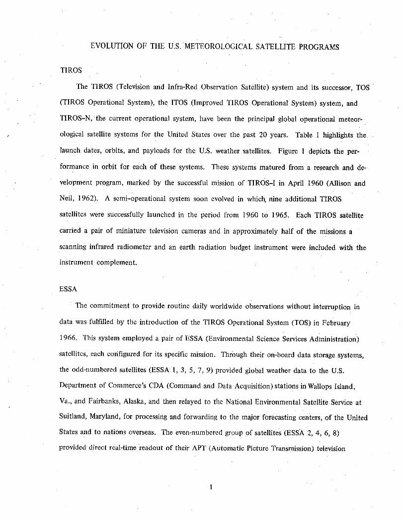
The TIROS (Television and Infra-Red Observation Satellite) system and its successor, TOS
(TIROS Operational System), the ITOS (Improved TIROS Operational System) system, and
TIROS-N, the current operational system, have been the principal global operational meteor-
_, ological satellite systems for the United States over the past 20 years. Table t highlights the
launch dates, orbits, and payloads for the U.S. weather satellites. Figure 1 depicts the per-
formance in orbit for each of these systems. These systems matured from a research and de-
velopment program, marked by the successful mission of TIROS-I in April 1960 (Allison and
Neil, 1962). A semi-operational system soon evolved in which, nine additional TIROS
satellites were successfully launched in the period from 1960 to 1965. Each TIROS satellite
carried a pair of miniature television cameras and in approximately half of the missions a
scanning infrared radiometer and an earth radiation budget instrument were included with the
instrument complement.
ESSA
The commitment to provide routine daily worldwide observations without interruption in
data was fulfilled by the introduction of the TIROS Operational System (TOS) in February
1966. This system employed a pair of ESSA (Environmental Science Services Administration)
satellites, each configured for its specific mission. Through their on-board data storage systems,
the odd-numbered satellites (ESSA 1, 3, 5, 7, 9) provided global weather data to the U.S.
Department of Commerce's CDA (Command and Data Acquisition) stations in Wallops Island,
Va., and Fairbanks, Alaska, and then relayed to the National Environmental Satellite Service at
Suitland, Maryland, for processing and forwarding to the major forecasting centers, of the United
States and to nations overseas. The even-numbered group of satellites (ESS)_ 2, 4, 6, 8)
provided direct real-time readout of their APT (Automatic Picture Transmission) television
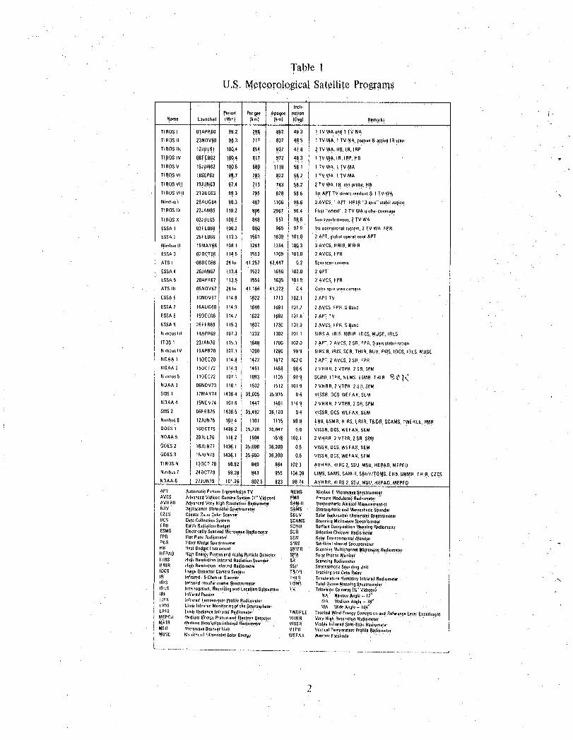
Table !
U.S. M,eteoro!ogica!Satellite Profanes
hloll.
Pe od Pergee ,_poqee nation ,;Name Launched {Mm) !km) Ikm) (0eg! Rema!k_
r ROSI 0!APR60 9_.2 79§ 867" 4_13 I TV.WA and1 TV _A
TIROS II 23NOV60 98,3 717 • 837 '_8.5 I TV.WA, 1TV.I_A. passive_ aclive IR scan
TIROS I1! 12JUL61 100.4 8_4 837 47`.8_ 2 TV-WA.HI_. IR, IRP " "
TIBO$ IV qeFEB62 QO.4 817 972 48.3 I TV.W,,_,I1_,IRe, HB
TIROS V 19JUN62 10q.5 660 1] !9 5;.1 I TV-WA, ] TV.MA
TIROS v llISEP62 96.7 7,83 822 511.2 1TV.WA, I TV.MA
TIROS V, 19._UN63 97.4 _!3 7_,3 i8.2 2 TV-WA, I1t, ior_probe, H6
TIROS VIII 210EC83 99.3 798 878 586 1st_'PT TV d.reetreadou!& 1TV-WA
NimbusI 28AUG64 98.3 467 1106 96.6 3 AVCS, 1APT, HRIR "3._xis" stabilization
TI ROSIX 22JAN65 119.2 806 2967 96.4 First"wheel*', 2 TV.W._globalcoverage
TIROS X 02JUL66 100.6 848 957, 98,.6 Sun syochronous,2 TV.WA
ESSA1 03FEB66 100.2 800 965 97.9 Isl operationalsystem,2 TV.WA, FPR
ESSA2 28FE656 113.3 1561 1639 101.0 ' 2APT, global operationalAPT
Nimbus II 15MAY66 108.1 1248 t354 I 1q03 3 AVCS, HRIR, MRIR
ESSA3 020CT6_ IH.5 1593 !709 I _Q!.0 2AVCS, FPR "
ATS I 06DEC66 24hr 41,257 42,447 0,2 Spin scancamera
ESSA4 26JAN67 113.4 1522 1656 102.0 2 APT
ESSA5 20APR67 113.5 1,_56 1635 I 101,9 2AVCS, FPR
ATS III 05NOV67 24hi 41,166 41,222 0,4 Colorsp,nscaneamela
ESSA6 10NOV67 114.8 1622 1713 !02,1 2AP[ TV
ESSA7 16AUGB8 114.9 1646 !691 101.7 2 ,_.VCS,FpR. S Band
ESSA8 150EC58 1141 1622 1682 / 101.8 2APTTVESSA9 26FEB69 1153 1637 1730 J 1019 2AVCS, FPR,SBand
Nimbus IH !4APR69 1073 1232 1302 1011 SIRSA, IRIS, MBIR, IBCS, MUSE, IBLS
ITOS 1 23JANT0 115.1 1648 1700 102.0 2 ._PT,2 AVCS, 2 SR, FPR,3.axisstablhtation
NimbusIV 15APB70 107.1 1200 1280 999 SIRS0, IRIS, SCR,THIR, BUV, F_S, [0CS. IRLS. I_US5
NOA,_,1 110EC70 114.8 422 1,_7,2 1020 2 APT.2 AVCS, 2 SR. FPR
NOAA 2 15OCT72 114.9 1451 1458 986 2 VHRR. 2 VTPR. 2 SR.SpM
N,mbus5 1105C72 107.1 1093 1105 999 SCMR,ITPR, NEMS, ESMR,THIR _ _' '_
NOAA 3 06NOV73 116.1 1502 1512 101.9 2 VHRR. 2 VTPR, 2 SR.SPM
SMS1 llMAY74 1436 4 35,605 35,975 06 VISSR,DCS,WEFAX,SEM
NOAA4 15NOV74 101.6 447 1461 1149 2 VHRR, 2 VTPR. 2 SR.SPM
SMS2 05F5075 1436.5 35 482 36,i03 0.4 VISSR,OCS,WEFAX,SEM
N_mbu$6 12JUN75 107,_ 1101 1115 99.9 ERl_,ESMR,HIRS,LRIR. T&OR, SCAMS,TWERLE. PIeR
GOES I 160CT75 1436.2 35,728 35.847 O.8 VISSR,OCS,WEFAX.SEM
NOAA5 29JUL76 116.2 1504 151_ 102.1 2 VHRR. 2 VTPR, 2 SR,SPM
GOES2 16JUN77 1436.1 35,600 36,200 0.5 VISSR,OCS.WEFAX.SEM
GOES3 15JUN79 !436.1 35,600 36.200 0.5 VISSR,DCS,WEFAX, SEM
TIROS-N 130CT 78 98.92 849 804 1023 AVHRR, HIR,32, SSU,MSU, HEPAO.MEPEO
N.mbus7 240CT78 99,28 943 955 19409 LIMS,SAMS,SAM.H, SI_UV/TOI_S,ERB,SMMR. THIR. CZCS
8;_3 9874 AVHRR. HIRS.2, SSU,MSU.HEpAO,MEPEO• NOAA.6 27JON79 101.26 8075
APT AutomaticPictureTransmissionTV _EMS NimbusEMie¢owayeSpectrometerAVCS AdvancedVidiconCameraSYstem1" Vidieon PMR P_essureModulatedRadi'_mHer
] AVltRR AdyancedVeryHighResolutionBadomee'r S_M.II StratosphericAerosolMe=asuremeot-tBUY _ckscat_erUltravioletSaectromet_ SAMS StratotphalicandMesosph_ri_Sou}lderCZCS Coa_lelZoneColor_canner SBbY SolarBackscatterUltravioletSpectre'meterOCS DataCollectionSystem SCAMS ScanningMicrowaveSpectromeerERR EarthRadiationBudget SCMR SurfaceCompositionMabpnoRedemoteESMR ElectricallyScannedMic'owaveRadiometer SCR SelectiveChopperRadiometerFPR FlatPlateRadiometer SEM Sola_EnvironmentalMonitorFW8 _iIter WedgeSDeetrnrueter SIRS Sat.llitq Inlrar_dSp_,ctrometerHB HeatBudgetInstrument SMMR Scannin_MdtichannelMicrowaveRadiometerHEPAO HighEnergyPrntonandAlphaParticleDetector S_ _olarProtonM_nilor'HIRS HighResolutionInfraredRadiationSoundei" SR 8eannin._RadiumetelHRIR HighResolutionIntra:_dRadiometer SSU StratosphericSoundingUmtIOCS !mageDissectorCameraSyst._m T_D!I TrackingandDataI_elavIR infrared. 6 ChannelScanner THIn TemperatureHumd y n ared Radiometer %IRIS infraredInterterr)meterSpectrometer TOMS TotalOzoneMapping8pectro_neterIRLS .reCreation,Recordingand LocationSul_$vr_em rv TelevisionCe;lzeral(_" Vid!con)IRe nfraredPassive NA NarrowAngle-- 1_h'PF_ infraredTenlper_tureProfileRedamuser MA MediumAngle- 78_LIt,tS LimbInfraredMonitorin(Jof theStrafosohe_e_ WA Wide_n91e- 10__LRill .imb Radiar_ceInfraredRadiometer TWERLE TropicalW_Id EnergyCon_.,aso endRefere_e LevelExperimentMEPEO MediumE'na_gyPrelimandElectronDetector VHRR VeryHigh8esphJtionRadlometetMRIB MediulnRe==o_utionInfrareclllRadlometer VISSR Visibleli_fraredSpin-Sca.:_RauiomeeI_SU :'Ai_roweveScannerUnit VTPR VerticalTeml,er_tureProfileRadiometerMUSE Monitor_;t JI;ravioletSolarEnergy WEFAX WeathnrFacsimile
pictures to simple stations locatedaround the world. Nine ESSA satellites were successfully
launched between 1966 and 1969. One of them, ESSA-8,remained in operation until March
1976. Larger televisioncameras (2.54cm vidicon) developed for the Nimbus satellite program
were adapted for use on the ESSA series, providinga significant increase in the quality of the
cloud cover pictures over that obtained from the earlier TIROS cameras, which used a 1.27cm
vidicon(Schwalband Gross, 1969).
ITOS
The second decade of meteorological satellites was introduced by the successful orbiting
on January 23, 1970, of ITOS-I,* the second-generation operational weather satellite. This
satellite dramatically surpassed the capabilities of the predecessor ESSA satellites, moving rapidly
closer toward the objectives of the U.S. National Operational Meteorological Satellite System.
ITOS-I provided in a single spacecraft the"combined capability of two ESSA spacecraft-the direct
readout APT system, and the global stored images of the AVCS system. Additionally, ITOS-1 pro-
vided, for the first time, day-and-night radiometric data in real time, as well as stored data, for
later playback. Global observation of the earth's cloud cover was provided every 12 hours with
the single ITOS spacecraft as compared to every 24 hours with two of the ESSA satellites. A
second ITOS spacecraft, NOAA-1 (ITOS-A), was launched on December 11, 1970.
As the ITOS system evolved to become the ITOS-D system, the flexibility inherent in the
spacecraft design permitted a broader and more sophisticated array of environmental sensors to
be carried, with only minor changes to the spacecraft. This new sensor complement provided
day-and-night imaging by means of Very High Resolution Radiometers (VHRR's) and medium
resolution Scanning Radiometers (SR's) (Conlan, 1973). It included Vertical Temperature Profile
Radiometers (VTPR's) for temperature soundings of the atmosphere and a Solar Proton Monitor
*This spacecraft was originally designatedTIROS-M. After being placed into orbit, it was redesignated ITOS-1.Subsequent spacecraft in this serieswere named NOAA-1, NOAA-2, etc. by the National Ocean and AtmosphericAdministration, the successor to ESSA as operator of the system.
3

(SPM) for measurements of proton and electron flux. Six spacecraft (ITOS-D, E-2, F, G, H,
and I) were planned for the ITOS-D series. NOAA-2 (ITOS-D), the first satellite in this series,
was successfully launched on October 15, 1972. Three additional satellites of this type (NOAA-
3, NOAA-4, and NOAA-5) were placed into orbit in 1973, 1974, and 1976, respectively
(Fortuna and Hambrick, 1974). Due to the longevity experienced in orbit by the ITOS!NOAA
satellites. ITOS E-2 and I launches were cancelled. The ITOS system, as it matured, brought
closer the realization of the goals of the U.S. National Operational System.
The ITOS satellite system evolved from the proven technology of the TIROS and ESSA
spacecraft. Many devices and techniques employed on the earlier series were enhanced, and
the enhanced versions were used on the ITOS spacecraft. This orderly evolution permitted
growth from a spin-stabilized spacecraft to a 3-axis stabilized earth-oriented despun platform.
The principal objectives of this growth pattern during the evolvement from an R&D
satellite to a global operational system were improved performance, the provision for increased
quality and more frequent acquisition of meteorological data, and more timely dissemination of
the processed data to the users. The evolving system had to be compatible with the global
ground network of local receiving stations as well as the two principal command-and-data acquisi-
tion sites. Finally, the operational system had to be cost-effective and have the capacity for
future growth.
TIROS-N
The third-generation operational polar-orbiting environmental satellite system, designated
T1ROS-N, completed development and was placed into operational service in 1978. Eight space- - "
craft in this series wil! provide gJobal observational service from 1978 through 1984. This new
series has a new complement of data-gathering instruments. One of these instruments, the Advanced
Very High Resolution Radiometer (AVHRR), will increase the amount of radiometric information
for more _ccurate sea-surface temperature mapping and identification of snow and sea ice, in
4
addition to day-and-night imaging in the visible and infrared bands. Other instruments, contained
in a subsystem known as the TIROS Operational Vertical Sounder (TOVS), will provide impro_ced
vertical sounding of the atmosphere. These instruments are the High Resolution Infrared Radiation
" Sounder (HIRS/2), the Stratospheric Sounding Unit (SSU), and the Microwave Sounding Unit
(MSU). A Data Collection System (DCS) will receive environmental data from fixed or moving plat-
forms such as buoys or balloons and retain it for transmission to the ground stations. A Solar Envi-
ronmental Monitor is included to measure proton, electron, and alpha particle densities for solar
disturbance prediction (Hussey, 1979). Figure 2 depicts the evolution of the TIROS-ESSA-ITOS-
NOAA family of satellites.
The TIROS-ESSA-ITOS-NOAA spacecraft series was designed and built by RCA Astro-
Electronics under the technical management of the National Aeronautics and Space Administration,
Goddard Space Flight Center, and procured (operational series) and operated by the U.S.
Department of Commerce; National Oceanic and Atmospheric Administration.
NIMBUS
The Nimbus satellite program was initiated by the National Aeronautics and Space Admin-
istration in the early 1960's to develop an observational system capable of meeting the research
and development needs of the nation's atmospheric and earth scientists.
The general objectives of the program were: (1) to develop advanced passive radiometric
and spectrometric sensors for daily global surveillance of the earth's atmosphere and thereby pro-
vide a data base for long-range weather forecasting; (2) to develop and evaluate new active and
passive sensors for sounding the earth's atmosphere and mapping surface characteristics (Press
and Huston, 1968); (3) to develop advanced space technology and ground techniques for
meteorological and other earth-observational spacecraft; (4) to develop new techniques and
knowledge useful for the exploration of other planetary atmospheres; (5)to participate in global
observation programs (World Weather Watch) by expanding daily global weather observation
capability (National Research Council, 1978); and (6) to provide a supplemental source- of op,er,
ational meteorological data.f_
The Nimbus System was designated to be (l) the test bed for advanced instruments for
the future operational TIROS polar-orbiting satellites and (2) the research system for remote
sensing and data collection. The Nimbus spacecraft system was developed under NASA/GSFC
management, with the General Electric Company as the spacecraft integration contractor. RCA,
Hughes, ITT, T.I., and a number of other companies and universities provided sensors and data
processing and storage equipment for the Nimbus series. The project has matured to become
the nation's principal satellite program for remote-sensing research. Each new satellite in the
Nimbus series has represented significant growth in sophistication, complexity, weight, capability,
and performance.
A total of seven Nimbus spacecraft was successfully placed into orbit from 1964 through
1978 (Staff Members, 1965). The final spacecraft, Nimbus 7, was launched in No_zember t978.
This spacecraft was instrumented with sensors to monitor the atmospheric pollutants, oceano-
graphy, and weather and climate ,(Figure 3) (Staff Members, Goddard Space Flight Center
1976, Vostreys and ttorowitz, 1979). The payload consisted of eight instruments:
1. Scanning Multichannel Microwave Radiometer (SMMR)--Measures radiances in five
wavelengths and ten channels to extract informa:tion on sea surface roughness and wind-so,sea
surface temperature, cloud liquid water content, total water vapor content, precipitation (mean
droplet size), soil moisture, snow couer, and sea ice.
2. Stratospheric and Mesospheric Sounder (SAMS)--Measures .verticalconcentrations of H20
N20, metilane (CH 4), carbon monoxide :(CO), and nitric oxide (NO); measures :tempera_tureof
stratosphere to "_90km and trace constituenl:s.
3. Solar-Backscattered Ultraviole.tiTo,tal Ozone Mapping System ,(SB UV/TOMSJ-Measures
direct and backscattered solar UV to extract ingormation on variations of solar if, adiance,, vertical
distribution of ozone and total ozone on a global Oasis.
6
4. Earth Radiation Budget (ERB)-Measures short- and longwave upwelling radiances and
fluxes and direct solar irradiance to extract information on the solar constant, earth albedo,
emitted longwave radiation, and the anisotropy of the outgoing radiation.
5. Coastal Zone Color Scanner (CZCS)-Measures chlorophyll concentration, sediment
distribution, gelbstoff (yellow substance) concentration as a salinity indicator, and temperature
of coastal waters and open ocean.
6. Stratospheric Aerosol Measurement H Experimen t (SAM II)-Measures the concentration
and optical properties of stratospheric aerosols as a function of altitude, latitude, and longitude.
Tropospheric aerosols can be mapped also if no clouds are present in the IFOV.
7. Temperature-Humidity Infrared Radiometer Experiment (THIR)-Measures the infrared
radiation from the earth in two spectral bands (11 and 6.7_tm) both day and night to provide
pictures of cloud cover, three-dimensional maps of cloud cover, temperature maps of clouds,
land and ocean surfaces, and atmospheric moisture.
8. Limb Infrared Monitoring of the Stratosphere Experiment (LIMS)-Makes a global survey
of selected gases from the upper troposphere to the lower mesosphere. Inversion techniques are
used to derive gas concentrations and temperature profiles.
ATS, APPLICATIONS TECHNOLOGY SATELLITE
The increased launch vehicle capabilities available during the middle 1960's permitted
satellites to be placed at geostationary altitudes and thus provided atmospheric scientists with
a new dimension in observations, namely: continuous observations of almost one-third of the
earth's surface. A NASA research program involving geostationary satellites was implemented in
the Applications Technology Satellite (ATS) series. Although primarily designed to demonstrate
communications satellite technology, several of the ATS series carried high-resolution cameras
for atmospheric observation.
- - .-..,
--. .... Off-Decem_r-_7,_:,1966,ATS-1 was placed into geostationary orbit. One function of thisk
technology satellite was to demonstrate the capability of providing a picture of the western
hemisphere every 20 minutes through_the use of a spin-scan camera. Useful data was provided
from approximately 55°N to 55°S latitude. The ability to receive sequential photographs of
the same area improved the possibility of early detection of severe storms and tornadoes, and
provided real-time data of cloud and frontal movements.
A second technology satellite, ATS-3, was launched November 1967. This satellite, using
a multispectral spin-scan camera, returned the first color images of the full earth disc. Copies
of these pictures have been used for many applications in addition to meteorology. ATS-1.and
ATS-3 were developed by NASA GSFC, with Hughes Aircraft as the prime contractor (Suomi
and Vonder Haar, 1969).
The performance history of the Nimbus and ATS technology satellites is shown in Figure 4.
SMS/GOES (OPERATIONAL GEOSTATIONARY SATELLITE)
The successful application of atmospheric observations from geostationary altitudes led to
NASA's development of a satellite designed specifically for that purpose. This satellite, the
SMS/GOES, was designed and integrated by the Aeronutronic Ford Corporation's Western De-
velopment Laboratories. NASA's prototype SynchronOus Meteorological Satellite, SMS-1, was
successfully launched in May 1974. Placed over the equator at 45°W longitude, it provided con-
tinuous hemispheric coverage. The principal instrument for SMSis a 16-inch aperture telescope
for visible and infrared scanning. Built by the Santa Barbara Research Center and called VISSR "
(Visible and lnfrared Spin Scan Radiometer), tMs sensor permits day and night observation of
clouds and the determination of teinperatures, clt_ud heights, and wind fields (Johnson, 1979). "
The SMS also relays data received from remotely located data collection platforms such as
river gauges, ocean buoys, ships, balloons, and aircraft. Its space environmental monitor
8
(consisting of an X-ray sensor, an energetic particle sensor, and a magnetometer) detects un-
usual solar activity, such as flares, and measures the flow of electron and proton energy and
the changes in the geomagnetic field. Observation and forecasting of atmospheric phenomena
not specifically related to meteorology are thus possible on an operational basis (Corbell et al.,
1976).
Four additional satellites of the SMS design have been launched: SMS-2 on February 6,
1975; the first operational version, GOES-1 (Geostationary Operational Environmental Satellite),
on October 16, 1975; GOES-2 on June 16, 1977; and GOES-3 in June 1978. These opera-
tional satellites are owned and operated by NOAA. The SMS/GOES satellite history is depicted
in Figure 5.
The SMS/GOES satellites have been maneuvered to various stations to optimize the
data and support special tasks. The following is the disposition of SMS/GOES as of May
1980.
SMS-1 is at 130°W longitude, and SMS-2 is at 75°W. GOES-I is at 900W, but the
VISSR is inoperative. GOES-2 is at 105°W and GOES-3 is located at 135°W longitude.
GOES-2 is being used to relay weather products to this hemisphere and to assist under-
developed countries in the receipt of processed satellite data.
TIROS-N SPACECRAFT SYSTEM
The following section contains a more technical description of the TIROS-N system.
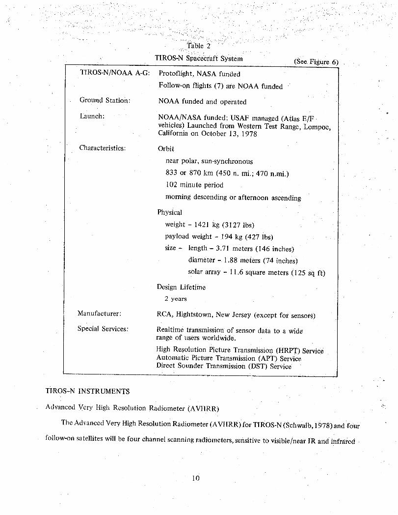
Table 2
TIROS-N spacecraft System (See Figure 6)
TIROS-N]NOAA A-G: Protoflight, NASA funded
Follow-on flights (7) are NOAA funded
Ground Station: NOAA funded and operated
Launch: NOAA!NASA funded; USAF managed (Atlas E!Fvehicles) Launched from Western Test Range, Lompoc,California on October 13, 1978
Characteristics: Orbit
near polar, sun-synchronous
833 or 870 km (450 n. mi.; 470 n.mi.)
102 minute period
morning descending or afternoon ascending•
Physical
weight - 1421 kg (3127 lbs)
payload weight - 194 kg (427 lbs)
size - length - 3.71 meters (146 inches)
diameter - 1.88 meters (74 inches)
solar array - 11.6 square meters (125 sq ft)
Design Lifetime
2 years
Manufacturer: RCA, Hightstown, New Jersey (except for sensors)
Special Services: Realtime transmission of sensor data to a widerange of users worldwide.
ttigh Resolution Picture Transmission (HRPT) ServiceAutomatic Picture Transmission (APT) ServiceDirect Sounder Transmission (DST) Service
TIROS-N INSTRUMENTS
Advanced Very High Resolution Radiometer (AVHRR) _
The Advanced Very High Resolution Radiometer (AVHRR) for TIROS-N (Schwalb; 1978) and four
follow-on satellites will be four channel scanning radiometers, sensitive to visible/near IR and infrared
l0
(IR) radiation. The instrument channelization (Table 3) has been chosen to permit multispectral
analyses which are expected to provide improved determination of hydrologic, oceanographic, and
meteorological parameters. The visible (0.6pm) and visible/near IR (0.9#m) channels are used to dis-
cern clouds, land-water boundaries, snow and ice extent, and when the data from the two •channels
are compared, an indication of ice/snow melt inception. The IR window channels are used to measure
cloud distribution and to determine temperature of the radiating surface (cloud or surface). Data from
the two IR channels will be incorporated into the computation of sea surface temperature. By using
these two data sets, it is possible to remove an ambiguity introduced by clouds filling a portion of the
field-of-view. On later instruments in the series, a third IR channel will add the capability for remov-
ing radiant contributions from water vapor when determining surface temperatures. Prior to inclusion
of this third channel, corrections for water vapor contributions will be based on statistical means using
climatological estimates of water vapor content.
TIROS Operational Vertical Sounder (TOVS)
The TIROS Operational Vertical Sounder (TOVS) system consists of three separate and
independent instruments, the data from which may be combined for computation of atmospheric
temperature profiles. The three instruments are:
a. The High Resolution Infrared Radiation Sounder (HIRS)
b. The Stratospheric Sounding Unit (SSU)
c. The Microwave Sounding Unit (MSU)
The TOVS has been designed so that the acquired data will permit calculation of (1) tempera-
, ture profiles from the surface to 10rob, (2) water vapor content at three levels of the atmosphere,
and (3) total ozone content.
High Resolution Infrared Radiation Sounder (HIRS]2)
The High Resolution Infrared Radiation SOunder (HIRS/2) is an adaptation of the HIRS!1
instrument designed for and flown on the NIMBUS 6 satellite. The instrument, being built by
11
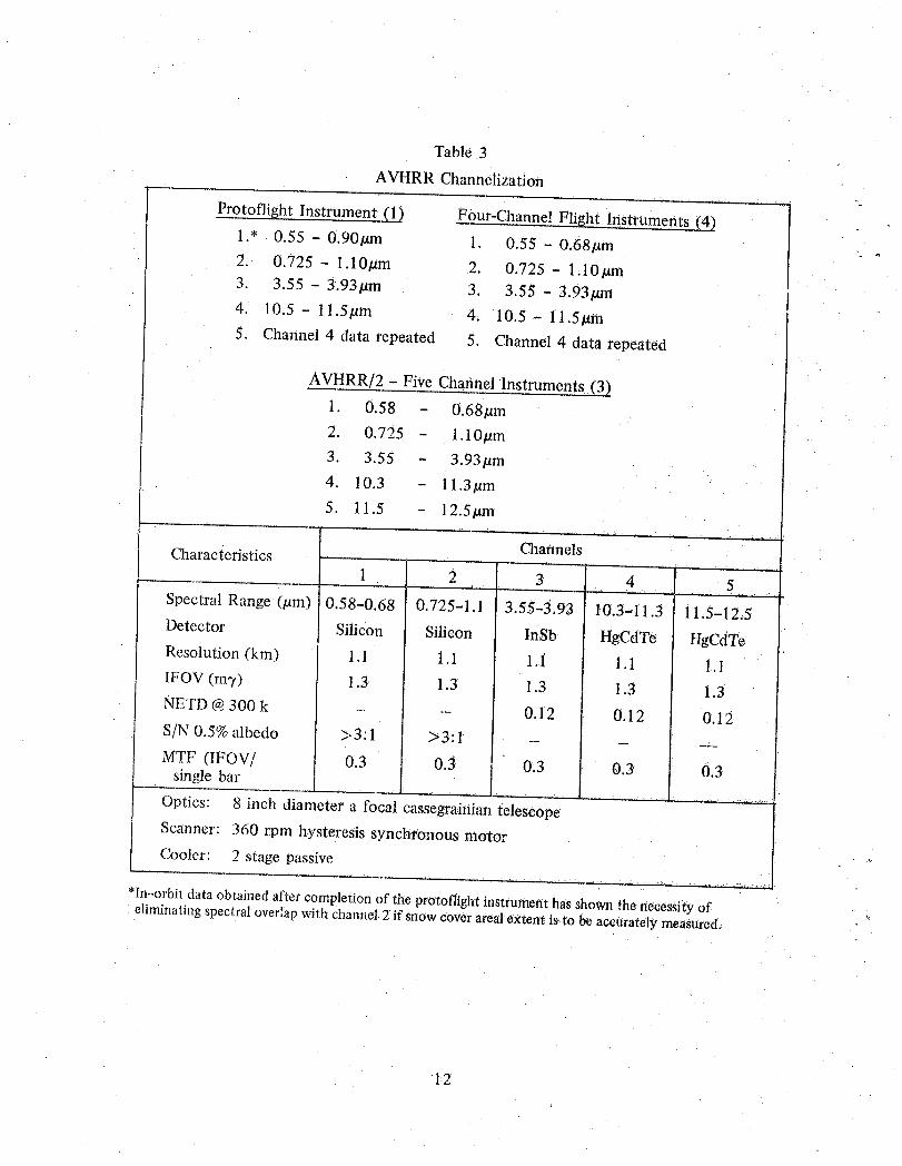
Table 3
AVHRR Channelization
Protoflight Instrument (1_ Four-Channe! Flight Instruments (4) ]1.* 0.55 - 0.90#m 1. 0.55 - 0,68#m [2. 0.725 - 1.10#m 2. 0.725- 1.10#m I3. 3.55 - 3.93#m 3. 3.55 - 3.93#m I4. 10.5 - ll.5/_m 4, 10.5- ll.5#m
5. Channel 4 data repeated 5. Channel 4 data repeated
AVHRR/2 - Five Channel Instruments (3)
1. 0.58 - 0.68#m
2. 0.725 - 1.10#m
3. 3.55 - 3.93btm
4. 10.3 - ll.3/am
5. 11.5 - 12.5#m
ChannelsCharacteristics
1 2 3 4 5
Spectral Range (#m) 0.58-0.68 0.725-1.1 3.55-3,93 10.3-.11.3 11.5-12,5
Detector Silicon Silicon InSb HgCdTe HgCdTe
Resolution (kin) 1.1 t.1 1.1 1.1 1.1
IFOV (mT) 1.3 1.3 1.3 1.3 1.3NETD @300 k
- I 0.12 0.12 0.12
S/N 0.5% albedo >3:1 >3:1 I - - --MTF (IFOV/ 0.3 0.3 0.3single bar [ 0.3 0.3
I
Optics: 8 inch diameter a focal cassegrainian telescopeScanner: 360 rpm hysteresis synchronous motorCooler: 2 stage passive
*In-orbi_dataobtainedafter completionof tlie protoflightinstrumenthas shownthe necessityofeliminatingspectraloverlapwith channel2 if snowcoverarealextent is to beaccuratelymeasured. '_
12¸
the Aerospace/Optical Division of ITT, measures incident radiation in 20 spectral regions of the
IR spectrum, including both longwave (15/_m) and shortwave (4.3gm) regions.
The HIRS/2 utilizes a 15cm (6 in) diameter optical system to gather emitted energy from
the Earth's atmosphere. The instantaneous field of view (IFOV) of all the channels is stepped
across the satellite track by use of a rotating mirror. This cross-track scan, combined with the
satellite's motion in orbit, provides coverage of a major portion of the Earth's surface.
The energy received by the telescope is separated by a dichroic beam-splitter into longwave
(above 6.4#m) energy and shortwave (below 6.4/xm) energy, controlled by field stops and passed
through bandpass filters and relay optics to the detectors. In the shortwave path, a second dichroic
beam-splitter transmits the visible channel to its detector. Essential parameters of the instrument
are shown in Table 4. Primary system components include:
a. Scan system
b. Optics, including filter wheel
c. Radiant cooler and detectors
d. Electronics and data handling
e. Mechanics
Stratospheric Sounding Unit (SSU)
The Stratospheric Sounding Unit (SSU) is supplied by the United Kingdom Meteorological
Office. It employs a selective absorption technique to make measurements in three channels. The
principles of operation are based on the selective chopper radiometer flown on Nimbus 4 and 5,
and the Pressure Modulator Radiometer (PMR) flown on the Nimbus 6. Basic characteristics are
shown in Table 5.
The SSU makes use of the pressure modulation technique to measure radiation emitted from
carbon dioxide at the top of the Earth's atmosphere. A cell of CO2 gas in the instrument's op-
tical path has its pressure changed (at about a 40Hz rate) in a cyclic manner. The spectral
13
characteristics of the channel and, therefore, the height of the weighting function is then deter,
mined by the pressure in the cell during the period of integration. By using three cells filled
at different pressures, weighting functions peaking at three different heights can be obtained.
The primary objective of the instrument is to obtain data from which stratospheric (25-50km)
temperature profiles can be determined. This instrument will be used in conjunction with the
HIRS/2 and MSU to determine temperature profiles from the surface to the 50 km level.
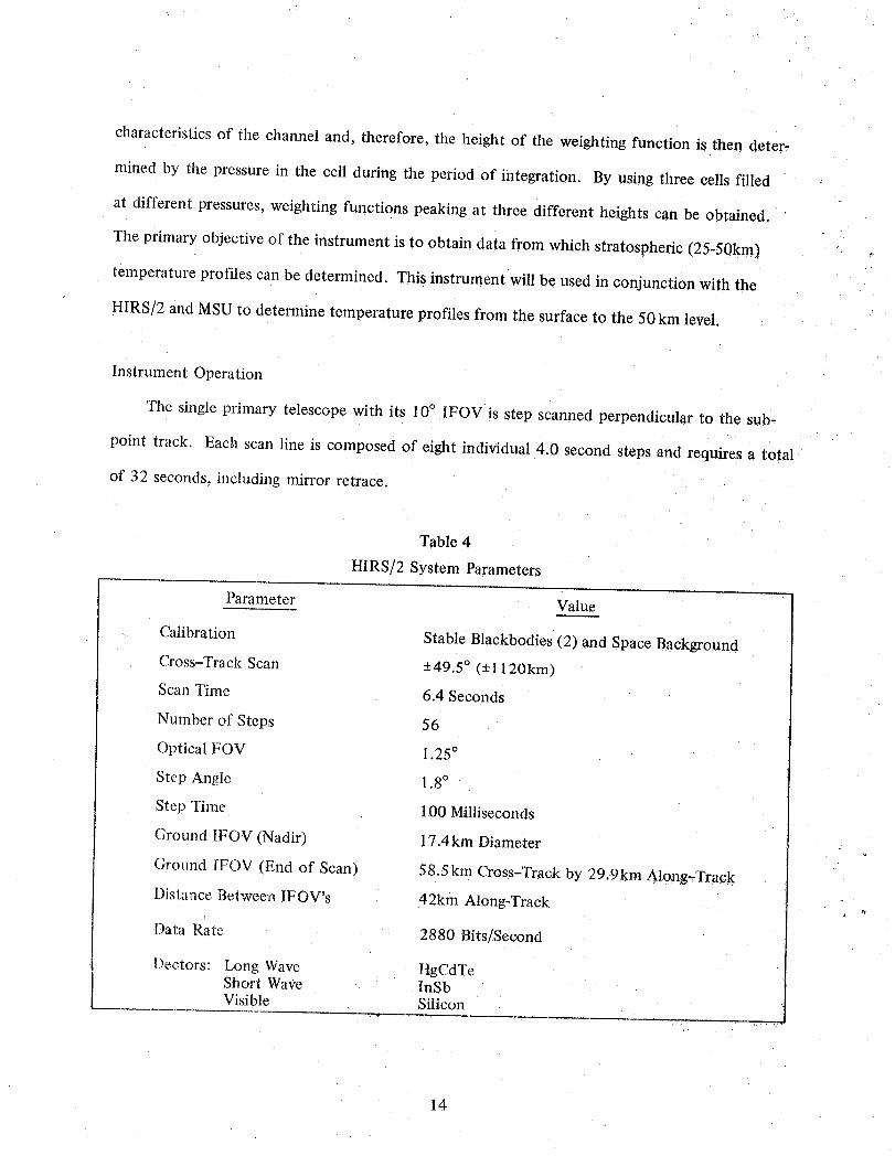
Instrument Operation
'I'he single primary telescope with its 10° IFOV is step scanned perpendicular to the sub-
point track. Each scan line is composed of eight individual 4.0 second steps and requires a total
of 32 seconds, including mirror retrace.
Table 4
HIRS/2 System Parameters
Parameter Value
Calibration Stable Blackbodies (2) and Space Background
Cross-Track Scan +49.5 ° (-+1120kin)
Scan Time 6.4 Seconds
Number of Steps 56
Optical FOV 1.25°
Step Angle 1.8°
Step Time 100 Milliseconds
Ground IFOV (Nadir) 17.4kin Diameter
Ground IFOV (End of Scan) 58.5km Cross-Track by 29.9km Along-Track
Distance Between IFOV's 42km Along-Track
Data Rate 2880 Bits!Second
Dectors: Long Wave HgCdTeShort Wave InSbVisible Silicon
14
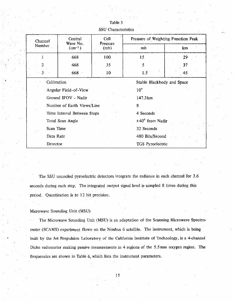
Table 5
SSU Characteristics
Central Cell Pressure of Weighting Function PeakChannel Wave No. PressureNumber (cm-1 ) (mb) mb km
. ,,
i 668 100 15 29
2 668 35 5 37
3 668 10 1.5 45
Calibration Stable Blackbody and Space
Angular Field-of-View 10°
Ground IFOV - Nadir 147.3km
Number of Earth Views/Line 8
Time Interval Between Steps 4 Seconds
Total Scan Angle -+40° from Nadir
Scan Time 32 Seconds
Data Rate 480 Bits/Second
Detector TGS Pyroelectric
The SSU uncooled pyroelectric detectors integrate the radiance in each channel for 3.6
seconds during each step. The integrated output signal level is sampled 8 times during this
period. Quantization is to 12 bit precision.
Microwave Sounding Unit (MSU)
The Microwave Sounding Unit (MSU) is an adaptation of the Scanning Microwave Spectro-
meter (SCAMS) experiment flown on the Nimbus 6 satellite. The instrument, which is being
- built by the Jet Propulsion Laboratory of the California Institute of Technology, is a 4-channel
Dicke radiometer making passive measurements in 4 regions of the 5.5mm oxygen region. The
frequencies are shown in Table 6, which lists the instrument parameters.
15
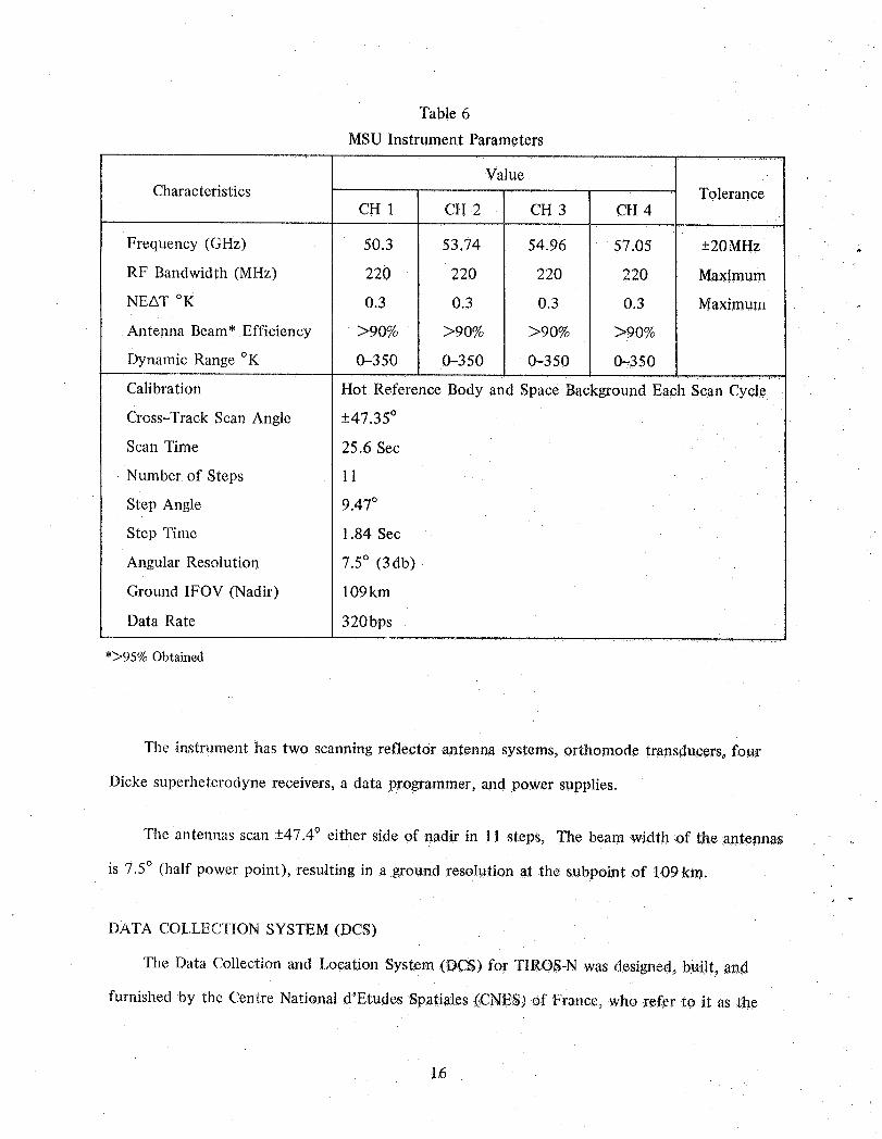
Table 6
MSU Instrument Parameters.... I..............
ValueCharacteristics Tolerance
CH 1 CH 2 CH 3 CH 4
Frequency (GHz) 50.3 53.74 54.96 57.05 +20MHz _
RF Bandwidth (MHz) 220 220 220 220 Maximum
NEAT °K 0.3 0.3 0.3 0.3 Maximum
Antenna Beam* Efficiency >90% >90% >90% >90%
Dynamic Range °K 0-350 0-350 0-350 0--350
Hot Reference Body and Space Background Each scan cycleCalibration
Cross-Track Scan Angle +47.35 °
Scan Time 25.6 Sec
• Number of Steps ! 1
Step Angle 9.47 °
Step Time 1.84 Sec
Angular Resolution 7.5° (3db)
Ground IFOV (Nadir) 109kin
Data Rate 320bps
*>95% Obtained
The instrument has two scanning reflector antenna systems, orthomode transducers, four
Dicke superheterodyne receivers, a data programmer, and power supplies.
The antennas scan -+47.4° either side of nadir in 11 steps, The beam width of the antennas
is 7.5° (half power point), resulting in a ground resolution at the subpoint of 109km.
DATA COLLECTION SYSTEM (DCS)
The Data Collection and Location System (DCS) for TIROS-N was designed, b!aJ!t,and
furnished by the Centre National d'Etudes Spatiales (CNES) of France, who refer to it as the
16
ARGOS Data Collection and Location System. The ARGOS provides a means for obtaining en-
vironmental (e.g., temperature, pressure, altitude, etc.) data, and earth location from fixed or
moving platforms. Location information, where necessary, may be computed by differential
doppler techniques using data obtained from the measurement of platform carrier frequency as
received on the satellite. When several measurements are received during a given contact with a
platform, location can be determined. The environmental data messages sent by the platformt}
will vary in length depending on the type of platform and its purpose. The ARGOS (DCS) sys-
tem consists of three major components:
a. Terrestrial platforms
b. On-board instrument
c. Processing center
Platforms
The terrestrial platforms may be developed by the user to meet his particular needs so long as it
meets the interface criteria defined by CNES. Before being accepted for entry into the system, the
platform design must be certified as meeting these criteria. By international agreement, entry into the
system is limited to platforms requiring location service or for those situated in polar regions out of
the range of the DCS on geostationary satellites. General platform criteria are shown in Table 7.
On-board Instrument
The on-board instrument is designed to receive the incoming platform data, demodulate the
incoming signal, and measure both the frequency and relative time of occurrence of each trans-
mission. The on-board system consists of three modules: the power supply and command inter-
face units, the signal processor, and the redundant receiver and search units.
Platform signals are received by the receiver, search unit at 401.65 MHz. Since it is possible
to acquire more than one simultaneous transmission, four processing channels [called Data Re-
covery Units (DRU)] operate in parallel. Each DRU consists of a phase lock loop, a bit synch-
ronizer, doppler counter, and a data formatter. After measurement of the doppler frequency,
17
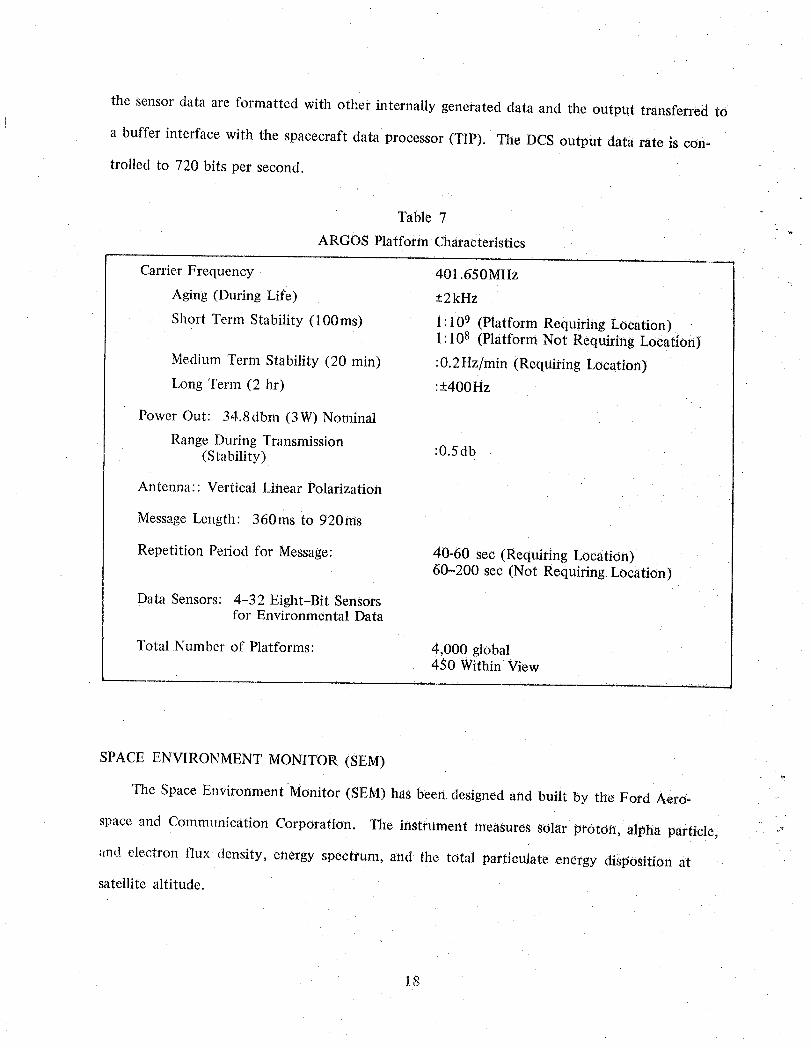
the sensor data are formatted with other internally generated data and the output transferred to
a buffer interface with the spacecraft data processor (TIP). The DCS output data rate is con-
trolled to 720 bits per second.
Table 7
ARGOS Platform Characteristics
Carrier Frequency 401.650MHz
Aging (During Life) -+2kHz
Short Term Stability (100ms) 1: 109 (Platform Requiring Location)1:108 (Platform Not Requiring Location)
Medium Term Stability (20 min) :0.2Hz/min (Requiring Location)Long Term (2 hr) :+400Hz
Power Out: 34.8dbm (3W) Nominal
Range During Transmission(Stability) :0.5 db
Antenna:: Vertical Linear Polarization
Message Length: 360ms to 920ms
Repetition Period for Message: 40-60 sec (Requiring Location)60-200 sec (Not Requiring. Location)
Data Sensors: 4-32 Eight-Bit Sensorsfor Environmental Data
Total Number of Platforms: 4,000 global450 Within View
SPACE ENVIRONMENT MONITOR (SEM)
The Space Environment Monitor (SEM) has been designed and built by the Ford Aero-
space and Communication Corporation. The instrument measures solar proton, alpha particle, ""
and electron flux density, energy spectrum, and the total particulate energy disposition at
satellite altitude.
18
The three components of the SEM are:
a. Total Energy Detector (TED)
b. Medium Energy Proton and Electron Detector (MEPED)
c. High Energy Proton and Alpha Detector (HEPAD)
This instrument is a follow-on to the Solar Proton Monitor (SPM) flown on the ITOS series
of NOAA satellites. The new instrument modifies the SPM capabilities and adds the monitor-
r ing of high energy protons and alpha flux. The package also includes a monitor of total energy
deposition into the upper atmosphere. The instrument will augment the measurements already
being made by NOAA's Geostationary Operational Environmental Satellite (GOES).
Total Energy Detector (TED)
The TED uses a curved plate analyzer and channeltron detector to determine the intensity
of particles in the energy bands from 0.3KeV to 20KeV. Four curved plate analyzers (two mea-
suring electrons, two protons) measure incoming particles reaching the instrument.
Medium Energy Proton and Electron Detector (MEPED)
The MEPED senses protons, electrons, and ions with energies from 30KeV to greater than
60 MeV. This instrument is comprised of four directional solid-state detector telescopes and one
omni-directional sensor. All five components use solid-state nuclear detectors. Outputs from the
detectors are connected to a signal analyzer which senses and logically selects those events which
exceed specific threshold values.
High Energy Proton-Alpha Detector (HEPAD)
The HEPAD senses protons and alphas from about 370MeV to greater than 850MeV. The
instrument is essentially a Cerenkov detector. The Cerenkov crystal is installed within a telescope
in association with two solid-state detectors; the telescope is shielded to establish the instrument's
field,of-view.
19
The .NOAA F and G spacecraft (Fig. 7) will be equipped with the SBUV (Solar Backscatter
Ultraviolet Instrument) and the ERBE (Earth Radiation Budget Experiment). These instruments
will be used to measure the earth's ozone and radiation to and from the earth's atmosphere.
THE EARTH RADIATION BUDGET EXPERIMENT (ERBE)
The requirements for the ERBE were specified to overcome the previous problems of ex-
isting radiation budget observations (Currata, !980). The experiment incorporates three sets of
radiometers on different satellite platforms. Two of the satellites are the sun-synchronous
TIROS-N/NOAA satellites with differing equatorial crossing times. The third satellite is the
medium inclination (i __46) Earth Radiation Budget Satellite (ERBS). This satellite is to be
Shuttle launched. The medium inclination orbit can be accomodated with a Shuttle launch from
the Kennedy Space Center in Florida. It is anticipated that a payload will be scheduled to fully
utilize the Shuttle capabilities permitting the launch of other free fl_cingsatellites or onboard
(Spacelab) experiments which are compatible with this orbital inclination. The free flyer will
be lifted from the pallet by the articulated arm. While still attached, the entire system including
instruments and spacecraft will be checked. Once free of the environment of the Shuttle, on-
board thrusters will propel the ERBS spacecraft to the nominal 600kin altitude orbit.
The 600kin orbit and the 460 inclination will provide an orbital precession rate relative to
the earth-sun vector of better than 180° per month. This precession rate will permit a minimum
of one observation per hour angle per month for each 1000km by 1000 km area in the tropics
and much better sampling at mid-latitudes. The combination of ERBS and the near-polar orbit,
ing satellites will provide a large number of samples uniformly distributed in space and time
permitting higher precision and less biased estimates of the monthly averaged radiation budgetcomponents.
The instrumentation to be used for the radiation budget observations consists of two parts:
a fixed field of view section and a scanner section. An artist's co_)cept of the instrumentation
20
on the ERBS is illustrated in Fig. 8. The fixed field of view section has 5 radiometers, 4 earth
viewing and one shuttered sun viewing. The earth viewing radiometers consist of pairs of broad-
band (0.2 to 50 + gm wavelength) and shortwave (0.2 to 5#m wavelength) detectors. The two
spectral bands are also represented by two different instantaneous fields of view, one of which
views the entire earth from limb to limb while the other has a restricted field of view with a
"foot print" of approximately 1000 km.t_
Both of these radiometers have cosine law detectors. The wide field of view radiometers
because of their cosine response and nadir viewing direction, measure the flux of upwelling radia-
tion from the observable earth at satellite altitude. These flux measurements will be used in
accurately determining the global radiation energy balance and its variation with season. These
observations of the fluxes at satellite altitude are the only earth flux observations which do not
require knowledge of the angular nature of the radiation leaving the earth. To meet the scienti-
fic requirements of the ERBS, transformation procedures must be defined to change the obser-
vations into the scientifically useable product.
The solar observations will be made with a cavity radiometer, based on the technology of
the Solar Maximum Mission. This type of detector will provide periodic observations of the
sun to extend the period of solar observations and will also serve as a secondary standard
through simultaneous solar observations with the cavity radiometer and all the earth viewing
detectors.
The separate scanning instrument consists of shortwave, longwave and broadband channels
which scan perpendicular to the velocity vector of the spacecraft. The instantaneous fields of
view of the scanning channels are 3° . Calibration of these channels will take place both through
observation of an internal blackbody source and observations of a diffuser plate exposed to
direct sunlight. The specifications of the ERBE instrumentation were developed with the co-
operation of a number of scientists at NASA, NOAA/NESS and several universities. The
21
implementation of the scientific objectives of the ERBS will be carried forward by a team of
scientists recently selected through an Announcement of Opportunity procedure.
The ERBS will carry two instruments in addition to the ERBE scanner and nonscanner. One
instrument is the SAGE-II (Stratospheric Aerosol and Gas Experiment) instrument which will
provide observations of the stratospheric aerosols, ozone, and nitrogen dioxide. Both ozone and
stratospheric aerosols are thought to have an effect on the earth's radiatiOn budget .and in turn,
are thought to be affected by the magnitudes of the shortwave and longwave fluxes passing through
the atmosphere. This is particularly true following major volcanic eruptions which inject particu-
lates and gases into the stratosphere. The ERBS instruments and the SAGE-II instrument will be
used in climate studies of the interrelationships between the earth radiation budget, stratospheric
aerosols and ozone. The second additional instrument on ERBS is the Halogen OccUltation Expe-
riment (HALOE) instrument. This instrument is part of a study of environmental quality and files
on ERBS as a satellite of opportunity.
VAS
GOES-D, E and F, which will be launched in the early and mid-1980's will carry the VAS
(Visible Infrared Spin-Scan Radiometer Atmospheric Sounder). This is an advanced version of
the Visible Infrared Spin-Scan Radiometer (VISSR) developed for world-widegeostationary
meterological satellite systems. The VISSRis a dual-band (visibleand infrared) spin-scanimag-
ing device utilized for clayand night, two-dimensional,cl'oud cover pictures. The VAS retains
tile VISSRdual-band imaging function. However,the infrared channel capabilitieshave been
expanded using a more complex detector configuration together with selectable narrow-band
optical filters. The additional spectral bands provided are sensitive to tile effects of atmospheric
constituents which makes it possible to determine not only the surface and cloud'top tempera-
tures, as in VISSR, but also the three-dimensionalstructure of the atmospheric temperature
and water vapor distribution.
22
The VAS system consists of a Scanner which contains a telescope assembly, and a separate
Electronic Module. The telescope assembly is a 40.6cm (16.0-inch) diameter aperture optical
system with an object-space scan mirror for accomplishing the N-S step scan (Staff Members,
1980(a)). The complete Scanner contains:
1. A position-controlled object-space scan mirror
2. A Ritchey-Chretien primary collecting optics subassembly
3. A set of secondary optics, optical filters, detectors and preamplifers for the visible
and infrared channels
4. A two-stage radiation cooler for passively cooling the infrared channel detectors
5. A separate optical focus drive assembly for the visible and the infrared channel
6. Two (a primary and redundant) scan milTor drive motor and optical position angle
encoder subassemblies
7. An optical subassembly with reduced size aperture to permit an inflight radiometric
check-of-calibration of the visible channels on the sun
8. A temperature monitored, heatable, calibration blackbody and motor drive/shutter
subassembly to permit an inflight radiometric calibration of the infrared channels
9. Eighteen scanner temperature sensors
10. A scan mirror stow (electromagnet latch) subassembly
11. High voltage power supplies for the visible channel detectors
12. A temperature-controlled twelve-position spectral filter wheel assembly for selecting
the infrared optical passband.
The VAS has six infrared detectors. Two have a subpoint resolution of 6.9 km (IGFOV of
0.192x0.192 mr) and are used primarily for imaging. Four have a resolution of 13.8 km (IGFOV
23
of 0.384x0.384mr) and are used for sounding information. The two small infrared channel
detectors are mercury-cadmium-telluride (HgCdTe) long-wavelength detectors. Two of the large
infrared channel detectors are HgCdTe. The other two are indium antimonide (InSb).
Although there are six VAS infrared detectors, only two will be in use during any satellite
spin period.
The following are the three VAS operating modes:
1. VISSR: The sensor operates in a normal cloud mapping mode.
2. Multispectral Imaging: This mode provides the normal VISSR cloud mapping function.
In addition, it supplies data in any two additional spectral bands selected with a spatial
resolution of 13.8 km. This mode of operation takes advantage of the condition that
the VAS infrared imaging detectors (small HgCdTe) are offset one scan line in the N-S
plane. Using the data from these detectors simultaneously produces a complete infrared
map when they are operated every other scan line. This allows using the larger detectors
during half of the imaging/scanning sequence period to obtain additional spectral
information.
3. Dwell Soundh_g: Up to twelve spectral filters covering the range 680cm "I (14.7#m)
through 2535 cm1 (3.9/_m) can b'e positioned into the optical train while the scan
mirror is on a single N-S scan line. In addition, the filter wheel can be programmed so
that each spectral band (filter) can dwell on a single scan line for from 0 to 255 space_
craft spins. Either the 6.9km or 13.8km resolution detectors can be selected for the
seven filter positions operating in tile spectral region 703cm -j (1.4.2_m) through 1490
cm-I (6.7/Jm). For tile remaining five spectral bands the 13.Skm resolution detectors
are used. Selectable frame sector size, position and scan direction are the same as in
the Multispectral Imaging (MSI) mode of operation (Montgomery and Endres, 1977).
24
In some of the spectral regions, multiple line data are required to improve the signal-to-
noise ratio of the sounding data. The total number of satellite spins at the same N-S scan line
position required to obtain the desired sounding data for all spectral bands is called the VAS
"spin budget." The VAS "spin budget" for sounding a N-S swath having a 30x 30 km resolu-
tion is approximately 157 spins. Therefore, with the appropriate interlacing of scan lines formed
by the detector FOV pairs, the time required to accomplish sounding over 0.65 ° N-S swath (400
km) with a resolution of 30x30 km will be 23 minutes.
THE DEFENSE METEOROLOGICAL SATELLITE PROGRAM (DMSP)
EVOLUTION
Data from DMSP satellites has been routinely transmitted directly to U.S. Air Force and Navy
ground terminals and Navy carriers since 1966. Previous spacecraft which have been launched
(Figure 9) have had a tactical (direct readout) as well as a strategic (stored data) capability.
Sixteen air transportable data receiving terminals are now located in the Philippines, Spain, Guam,
Okinawa, Alaska, the Canal Zone, Germany, Korea, the Kwajalein Missile Range, and the con-
tinental U.S. to provide tactical commanders with real time DMSP data. The Navy is currently
operating direct data readout sites at Rota, Spain and at San Diego, California.
In March 1969, DOD approved a joint-service development effort. As a result, a feasibility
model shipboard receiving terminal was developed by the Air Force with assistance from Navy
personnel attached to the DMSP System Program Office (SPO). This terminal was installed
aboard the USS Constellation and proved extremely effective in several deployments to South-
east Asia. A prototype station has since been placed in operation on the USS Kennedy and
production units are in operation on the USS Independence, the USS Kitty Hawk, the USS
Midway, and the USS Enterprise. All CV class carriers are slated for eventual receipt of this
equipment.
25
In December 1972, DMSP data were declassified and made available to the civil/scientific
community through the National Oceanic and Atmospheric Administration (NOAA) Nicho!s,
1975a; 1976; Brandli, 1976).
In September 1976, the first Block 51) satellite was launched. Although anomalies pre-
cluded collection of operational data immediately after launch, the satellite was restored to
nominal operational condition and provided meteorological data of previously unmatched quality.
The second, third, and fourth Block 5D satellites have subsequently been launched and placed
in operation (Figure 9).
DMSP spacecraft history prior to 1 Ju!Y 1965 is still classified. Since 1965, there have
been two major spacecraft models flown: B!ock 4, Versions A & B; and Block 5, Versions A,B, C, and D.
Block 4. Block 4 employed a pair of VIDICON cameras to acquire television pictures
showing the earth's cloud cover and some terrain features as they appeared in the visible wave-
length region. The resolution of these pictures was approximately 1.5 nautical miles at nadir,
but degraded rapidly toward the picture edge. A Supplementary system to roughly measure albedo
was also incorporated on later Block 4 spacecraft. This system of 16 thermopile sensors, known
as the "C" system, acquired data on energy emitte0 by large areas of the ea_'th in two se!ected
IR intervals: 0.4 to 4.0 micrometers (energy from reflected sunlight) and 8.0 to 12.0 micro-
meters (energy self emitted by the earth). Resolution was on the order of 100 nautical sq. miles.
Block 5. The first Block 5 was launched in February !970. Block 5 version A, B, C, re-
placed the VIDICON cameras in the "C" system with a new primary sensor known as the
Sensor Avenue Package (SAP) to gather Visual and Infrared data at improved resolutions. Visual
data and IR data were collected at one-third nautical mile resolution and smoothed to two
nautical miles. The one-third nautical mile data were available to U.S. Air Force Globa! Weather
Central (AFGWC), Omaha, Nebraska, while the smoothed data were routinely transmitted directly
26
1
to AF and Navy tactical sites around the globe. Versions B and C incorporated various special
sensors for vertical profiling of atmospheric temperature, for measuring precipitating electron
activity at spacecraft altitude, for atmospheric density profiling, etc. Many of these sensor package
packages have been improved for Block 5D.
Block 519. The first Block 5D was launched in September 1976. Although anomalies
precluded collection of operational data immediately after launch, the satellite was restored
to nominal operational condition and provided meteorological data of extremely high qual-
ity. The second, third, and fourth Block 5D satellites have subsequently been launched
and placed in operation. The 5D version included a new primary sensor, the Operational
Linescan System (OLS), which provided improved resolution of 0.3 nautical miles for both
visual and IR fine data and 1.5 nautical mile for smoothed data. The biggest improvement over
the SAP was the OLS resolution uniformity along the scan line. At 800 nautical miles from
nadir, the SAP experienced a degraded resolution of 13 nautical miles while the OLS main-
tained a resolution of two nautical miles or better.
The following section will describe the Block 5D-I and -2 instruments and system in more
detail (Nichols, 1975b):
DMSP Block 5D-l: DOD Meteorological Satellite Program satellites 5D-1 replaced the
5C models. DOD funded (Fig. 10(a)).
Ground Support: DOD funded and operated. The satellites are commanded and
controlled from sites located at Loring AFB, Maine (Site 2) and
Fairchild AFB, Washington (Site 1) which also receive stored data
from tape recorders on board the spacecraft. This data is relayed
to AFGWC at Offutt AFB, NE (Site 3) and FNWC at Monterey,
CA over a communication satellite link.
The Program's Command and Control Center (CCC) is at
Offutt AFB, Nebraska (Site 5). The 4000th Aerospace Applica-
tions Group (SAC) is responsible for the on-orbit commanding
through Sites 1 and 2 and the orbital telemetry analysis performed
at the CCC.
27
Launch: The first Model 5D-1 was launched on September 11, 1976 on a
Thor (LV-2F) booster by Aerospace Defense Command's 10th
Aerospace Defense Squadron at Vandenberg AFB, California.
Characteristics: Orbit: near polar circular sun-synchronous
Altitude: 833km (450 -+9nm)
Inclination: 98.7 -+ 1.3 degrees
Period: 101 minute
Sun Angle: 0 - 95 degrees (morning descending or afternoon
ascending, and noon orbits)
Physical:
weight 468 kg (1032 lbs)
payload weight 136 kg (300 lbs)
size - length 5.89 m (232 inches)
w/solar array extended
diameter 1.21 m (48 inches)
solar array 8.92 sqm (96 sq ft)
power 300 watts
Design Lifetime
2 years
Manufacturer: RCA, Hightstown, New Jersey (except for sensors)
Special Services: Realtime Direct Digital Transmission (DDT) of fine visual and
smoothed infrared imagery or smoothed visual and fine infrared
imagery to Air Force and Navy tactical sites world wide.
DMSP Block 5D-2: DOD Meteorological Satellite Program satellites 5D-2 replaces the
5D-1 models. DOD funded (Figure 10(b))
Ground Support: DOD funded and operated. The satellites are commanded and
controlled from sites.located at Loring AFB, Maine (Site 2) and
Fairchild AFB, Washington (Site 1) which also receive stored
data from tape recorders on board the spacecraft. This data is
relayed to AFGWC at Offutt AFB, NE (Site 3) and FNWC at
Monterey, CA over a communication satellite link.
The Program's Command and ContrOl Center (CCC) is at
Offutt AFB, Nebraska (Site 5). The 4000th Aerospace Applications
28
Group (SAC) is responsible for the on-orbit commanding through
Sites 1 and 2 and the orbital telemetry analysis performed at the
CCC.
Launch: The first Model 5D-2 is to be launched in 1981 on a Thor (LV-2F)
booster by Aerospace Defense Command's 10th Aerospace Defenser
Squadron at Vandenberg AFB, California.
Characteristics: Orbit: near polar circular sun-synchronous altitude
Altitude: 833 km (450 -+9nm)
Inclination: 98.7 +-1.3 degrees
Period: 101 minutes
Sun Angle: 0 - 95 degrees (morning descending or afternoon
ascending and noon orbits)
Physical:
weight 698 kg (1540 lbs)
payload weight 159 kg (350 Ibs)
size - length 6.39 m (250 inches)
w/solar panel extended
diameter 1.21 m (48 inches)
solar array 11.15 sq m (120 sq ft)
power 400 watts
Design Lifetime
3 years
Manufacturer: RCA Hightstown, New Jersey (except for sensors)
Special Services: Realtime Direct Digital Transmission (DDT) of fine visual and
smoothed infrared imagery or smoothed visual and fine infrared
imagery to Air Force and Navy tactical sites world wide.
,7
The primary objective of the 5D-2 development is to increase on-orbit life through improved
reliability. The 5D-2 design for reliability improvement is based on "Functional Module Redun-
dancy." The 5D-2 system is subdivided into functional modules which are made redundant and
independently controllable as to use of primary or backup. This approach allows switching
around failed units unti! both modules of a required function have failed. In addition to the
29
I;_F • I
.unctlonai Module Redundancy" design feature, the quality of parts, materials and processes
will be Significantly upgraded. Other objectives are increasing command and control perfor-
mance, oimpr°ving pro4,u,eibility, and providing minor performance improvements,
" " Th_:5D-1 Serisor Processing System (SPS) has incurred major alterations. The power
supply has been removed and, in the 5D,2 configuration, exists as a separate unit with redundant
supplies. The 5D-I SPS analog circuit boards have been ,moved to the PSU box, leaving the
SPS a pure digital subassembly. All SPS functional blocks-memory, processor, I/O and SDSand SDF formatters are redundant.
The RTD and SSP formatters and processors in the 5D,2 configuration are redundant and
are located in the Special Sensor Processing Unit (SPU).
The 5D-2 configuration includes three encrypters and four tape recorders; anaddition of
one each. The 5D-1 encryption interface box has been eliminated. The Output SwitchingUnit (OSU) is fully redundant.
BLOCK 5D INSTRUMENTS
OPERATIONAL LINESCAN SYSTEM (OLS)
,The,OLS is the primary data acquisition sYstem on the Block 5D satellite. This system
gathers and outputs in real time or stores mu!ti,orbit day and night visual and infrared spectrum
data from earth scenes for transmission to ground stations with appropriate calibration, indexing,
and auxiliary'signals. Data is ,collected, stored, and transmitted in fine (0.3 nm) or smoothed,(1_5rim) resolution.
Fine Resolution Visual Data
Tile visual daytime response of the OLS is in the spectral range of 0.4 to 1.0 microns to
provide maximum constrast between earth, ,seo,and clo,uds ill the image field, The visual fine
resolution (0.3nm x 0.3nm) is provided for day scenes only,
3O
• ; "... ,
Smooth Resolution Visual Data
The smooth resolution (1.5nm x 1.5nm) visual data is provided across a dynamic range
fi'ot_afull sunlight down to quarter moonlight. Night time visual data is provided from a photo-
' a_.tliLplc_'tube operated in the same spectral range and energized automatically as the radiance
decreases. Daytime, smooth resolution data is derived from f'me mode data by analog and digital
_lata processing by the OLS. Five fine mode resolution cells are averaged along the scan line to
produce a series of 0.3nm x 1.5nm cells. Then five such cells are digitally averaged along the
_:rackto produce a single smooth resolution cell, 1.5nm x 1.5nm.
l:ine Resolution Infrared
'H_eOLS infrared detector is a segmented tri-metal (HgCdTe) detector operating at approxi-
mately 105I( with a spectral response of 8.0 to 13.0 microns to provide optimal detection of
i_oth water and ice crystal clouds. The sensor output is normalized to equivalent blackbody
•!,::,_q:,eratureof the radiating object such that the sensor output voltage is a linear function of
,.'ce_ctemperature. The tri-metal detector is accurate to within one degree K rms across the
!_:'mt_,::raturerange 210-310 degrees K.*
Smoo!la Resolution Infrared
lhe Smooth Resolution data is obtained from fine Resolution Infrared data in the same
_.i__e_ a,; described for tlm smooth resolution visual data. Fine mode visual and infrared data
,,.-_:__._tbered through the same optics and are digitally identified; the smooth mode data are
_dsodigitally identified. Thus corresponding visual and infrared data cells maintain a unique
on,-.to_onc location correspondence throughout the data processing chain.
;)t S Data Processing
o "FI_cOLS data processing subsystem performs command, control, data manipulatory, stor-
ewide,,:tnd management functions. All data is processed, stored, and transmitted in digital format.
_:Withb.4, theOLS1RSpectralBandwaschangedfrom 8-13/amto 10.5-12.6/amto improvethe sea surface_cmpcrature resolution.
31
Special Sensor data and OLS telemetry data are merged by the OLS into the smooth data
stored format.
OLS Data Transmission
S-band transmitters are provided for data transmission. Two may be operated simultane-
ously for stored data playback. A third S-band transmitter is dedicated to transmission of
Direct Digital Transmission (DDT) to tactical sites world wide at 1.024 Mbps. DDT data is
normally encrypted.
The OLS system including the Sensor Subsystem, Signal Processing System, and the Re-
cording Subsystem weighs about 200 lbs and requires 170 watts power.
The 5D-20LS System has the same performance requirements as the 5D-1 System as
previously described. The basic premise of the 5D-20LS is to increase overall system reliability
by providing functional redundant circuitry, although some changes, such as increased IR digiti-.
zation (from 7 to 8 bits), and improved sensitivity to low temperature values (190 ° -210°K)
have been incorporated.
Characteristics of the Operational Linescan System (OLS)
Meteorological Data Collected in Visible and Infrared Spectra
Visible Data Collected as 0.3nm x 0.3nm during day and 1.5nm x 1.5nm at night
Infrared Data Collected as 0.3nm x 0.3nm at all times
Oscillating Scanner Collects Data in Both Directions Along 1600nm Swath.
Near Constant Resolution as a function of Scan Angle
Three Digital Tape Recorders for Data Storage
Each Recorder can store 20 minutes of' interleaved visual and infl'ared 0.3nm x
0.3nm of data.
Analog Filtering and Digital Averaging is used to smooth data to 1.5nm x 1.5nm
for on board global storage.
32
Each recorder can store 400 minutes of interleaved visual and infrared 1.5nm x
1.5nm of data.
Tele_ '_try and special meteorological sensor data are included within the primary
smoothed data stream.
Real time encrypted transmission of 0.3nm and 1.5nm data.
, SPECIAL SENSOR H (SStt)-A HUMIDITY, TEMPERATURE, AND OZONE SOUNDER
This instrument is an infrared multispectral sounder for humidity, temperature and ozone.
Soundings of temperature and of humidity and a single measurement of ozone is provided for
vertical and slant paths lying under and to the side of the sub-satellite track.
The SSH is a 16-channel sensor with one channel (1020 cm-1) in the 10-micrometer ozone
absorption band, one channel (835 cm-1) in the 12-micrometer atmospheric window, six channels
('74"7,725,708,695,676,668 cm-1) in the 15-micrometer CO2 absorption band, and eight channels
(from 453 cm-1 to 333 cm-1) in the 22- to 30-micrometer rotational water vapor absorption band.
The instruxnent consists of an optical system, detector and associated electronics, and a scanning
mirror. The scanning mirror was stepped across the satellite subtrack, allowing the SSH to view 25
separate columns of the atmosphere every 32 s over a cross track ground swath of 2000 kin. While
the scanning mirror is stopped at a scene station, the channel filters are sequenced through the field
of view. The surface resolution is approximately 39 km at NADIR. Radiance data are transformed
into temperature water vapor and ozone profiles by a mathematical inversion technique.
A Cassegrain objective forms a 2.7 degree FOV centered on an axis parallel to the flight path.
" A step-rotating diagonal scanning mirror scans the FOV according to a pre-established scan program
m a plane normal to the flight path.
The SSH instrument weighs 29 pounds and consumes 8 watts power.
33
Spacecraft F-1 through F-4 carried the SSH-1 as described. SSH units starting with F-5
are designated SSH-2 and do not include the spectral channel for ozone sounding. That filter
has been replaced by an atmospheric window channel at about 800/_m.
SPECIAL SENSOR M!T (SSM/T)-A PASSIVE MICROWAVE TEMPERATURE SOUNDER
The SSM!T is a 7-channel scanning passive microwave radiometer which measures radiation
in the 50-60GHz frequency region to provide data for temperature profiling from the earth's
surface to above 30kin. The SSM/T scans in synchronization with the SSH (an infrared tempera-
ture and humidity sounder). The microwave sounder complements the infrared sounder by
providing temperature sounding over previously inaccessible cloudy regions of the globe. Tem-
perature profiles to higher altitudes are also provided (than was previously possible with infrared
sensors alone).
The SSM/T will operate in the 50-60GHz absorption band of molecular oxygen. Since the
mixing ratio of oxygen is essentially constant in the atmosphere, the contribution of any layer
of the atmosphere to the total signal of a given frequency received by a radiometer flown on a
spacecraft is primarily a function of the temperature and density of the layer and the amount
of absorption in the atmosphere above the layer. By choosing frequencies with different absorp-
tion coefficients on the wing of the 02 absorption band, a series of weighting functions peaking
at preselected atmospheric heights may be obtained. Frequencies were chosen to obtain seven
channels with weighting functions peaking at altitudes ranging from the surface to above 30 km.
The surface channel at approximately 50GHz was chosen to permit removal of background
terrain contributions to tile channels which peak in the lower atmosphere. Other frequencies
were chosen (Table 8) to peak at altitudes that produce an optimum temperature profile.
The Multi-channel, Single Antenna
Radiometer scans across the NADIR track on seven scan positions and two calibration
positions (cokt sky and 300 deg K). The dwell time for the crosstrack and calibration positions
34
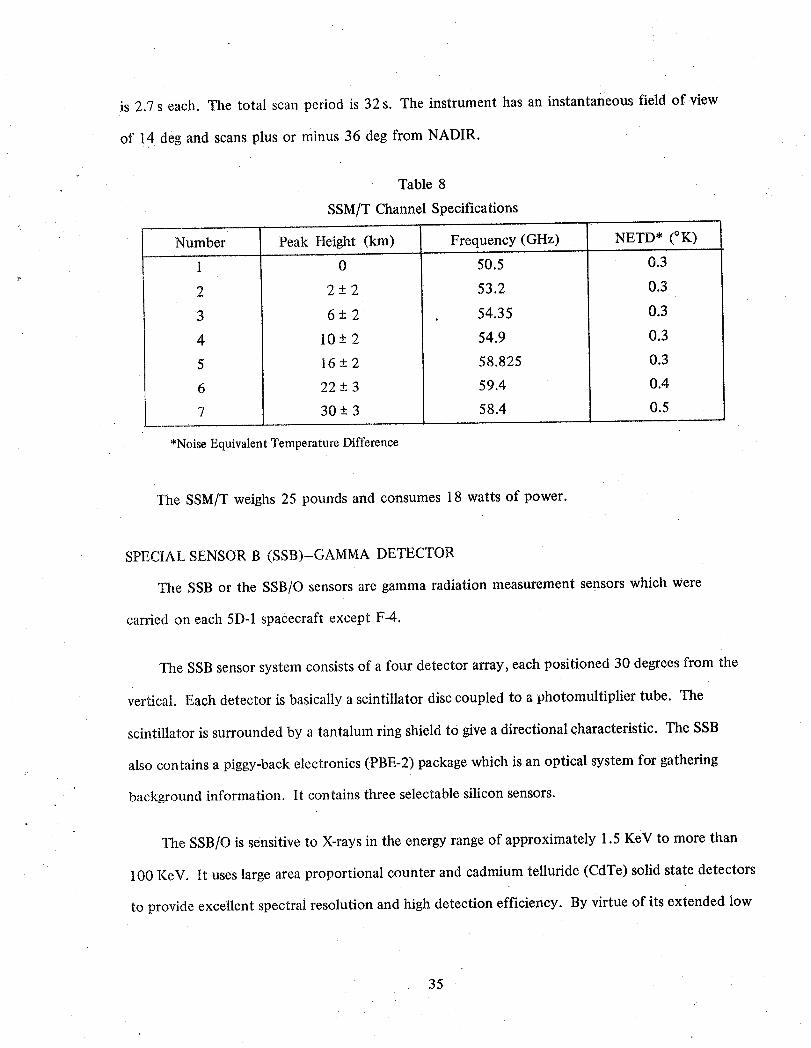
is 2.7s each. The total scan period is 32 s. The instrument has an instantaneous field of view
of 14 deg and scans plus or minus 36 deg from NADIR.
Table 8
SSM/T Channel Specificationsr
Number Peak Height (km) Frequency (GHz) NETD* (°K)
1 0 50.5 0.3
2 2 +-2 53.2 0.3
3 6 +-2 54.35 0.3
4 10 -+2 54.9 0.3
5 16 -+2 58.825 0.3
6 22 -+3 59.4 0.4
7 30 + 3 58.4 0.5
*NoiseEquivalentTemperatureDifference
The SSM/T weighs 25 pounds and consumes 18 watts of power.
SPECIAL SENSOR B (SSB)-GAMMA DETECTOR
The SSB or the SSB./O sensors are gamma radiation measurement sensors which were
carded on each 5D-l spacecraft except F-4.
The SSB sensor system consists of a four detector array, each positioned 30 degrees from the
vertical. Each detector is basically a scintillator disc coupled to a photomultiplier tube. The
scintillator is surrounded by a tantalum ring shield to give a directional characteristic. The SSB
also contains a piggy-back electronics (PBE-2) package which is an optical system for gathering
background information. It contains three selectable silicon sensors.
The SSB/O is sensitive to X-rays in the energy range of approximately 1.5 KeV to more than
100 KeV. It uses large area proportional counter and cadmium telluride (CdTe) solid state detectors
to provide excellent spectral resolution and high detection efficiency. By virtue of its extended low
35
energy response, the SSB/O is able to identify signals associated with Bremsstrahlung generated by
energetic electrons precipitating in the upper atmosphere.
SPECIAL SENSOR J* (SSJ*)-SPACE RADIATION DOSIMETER
The SSJ* measured the radiation dose in silicon under aluminum shielding of four thicknesses
representative of the Block 5D DMSPspacecraft. The dosimeter was launched aboard the first
Block 5D satellite (F-1).
The interest,in such data was engendered by the discovery of tile "softness" 0f"¢_urren_'CMOS
circuitry to radiation (104 rads results in failure) coupled with the present substantial uncertainty
and controversy concerning the natural energetic electron dose received by a satellite in a low polar
orbit. Direct measurement of this dose, correlated with performance of onboard circuitry;_as
therefore of crucial importance in providing data for planning of future missions (particularly where
use of CMOScomponents is envisioned).
The dosimeter used technology proven by flight aboard many USAF and NASA, satellitb_,
The instrument (onsist_d of four separate single-detector units, each using small cubical lith'iiam
drifted silicon detector_ to perform two major functions. First, it directly measured the ionization
in the silicon cgB_"cauged by riatural radiation (the radiation dose). Second, the dosimeter served
as an electron-protola Sl_etrometer, thus yielding the fluences of energetic electrons and protons
encountered in the DMSPorbit as a function of time.
A space radiation dosimeter is scheduled to fly on spacecraft F-7. Although differentin
manufacture, its operational objectives remain essentially the same as the 5D-1 dosimeter carried
on F-1. -
SPECIAL SENSOR D (SSD)-ATMOSPHERIC DENSITY SENSOR
'File Atmospheric Density Sensor (SSD) provides a measure of major atmospheric constituents
(Nitrogen, Oxygen and Ozone) in the earth's thermosphere (I O0 to 250kin in altitude) by
36
,,
making earth-limb observations of the ultraviolet radiation from this atmospheric region. The
sensor measures the radiation emitted in the ultraviolet spectral region from excitation of mol-
ecular nitrogen by impinging solar radiation. The intensity of the emitted radiation is proportional
to the excitation rate and the number of molecules at any given altitude. Funneltrons and a photo-
multiplier tube will detect the radiation after it passes through a collimator which provides a
0.1 x 4.0° field-of-view. The SSD is mechanically driven to scan vertically through the earth's
limb in about 30 seconds. The instrument provides approximately 50 sets of density profiles
on the daylight portion of each orbit.
The SSDis currently being evaluated aboard the DMSP F-4 satellite launched in June 1979.
This is an experimental sensor with no current Program Office plans to integrate it onto subse-
quent 5D spacecraft.
SPECIAL SENSOR J (SSJ)-PRECIPITATING ELECTRON SPECTROMETER
A small, lightweight (3 lb) sensor, the SSJ counts ambient electrons with energies ranging
from 60 eV to 20 KeV. Utilizing a time-sequenced variable electrostatic field to deflect the par-
ticles toward the channeltron detector, the sensor determines the number of electrons having
energies within certain sub-ranges of the 60 eV to 20 KeV spectrum.
The SSJ is an electron spectrometer that detects and analyzes low energy electrons precipi-
tating into the atmosphere producing the auroral display.
The SSJ units for Block 5D-2 will incorporate the capability to measure precipitating pro-
tons in the 50eV to 20KeV energy range as well as electrons measured on 5D-1. It is expected
that this change will give new information relative to magnetic substorm activity.
SPECIAL SENSOR C (SSC)-SNOW/CLOUD DISCRIMINATOR
The Snow/Cloud Sensor is an experimental unit that is being used in conjunction with the
OLS sensor on spacecraft F-4. The experiment being performed by the simultaneous in-orbit
37
use of these two sensors is primarily that of proving the proposition that snow/cloud scene dis-
crimination can be obtained though the combination of near IR (1.6 micrometer wavelength)
sensor data and OLS L-Channel (visual) information.
.The Snow/Cloud Sensor is a "push-broom" scan radiometer that will depend upon orbital
velocity of the 5D spacecraft to provide the along track scan and a linear array of 48 detectol
elements at the image plane of a wide angle lens to provide a 40.2 ° cross track scan. The sensor
depends upon reflected solar energy in the 1.51 to 1.63 micrometer spectral band for its input
signal.
SPECIAL SENSOR M/I (SSM/I)-MICROWAVE ENVIRONMENTAL SENSOR SYSTEM
The SSM/I is currently undergoing system development for integration aboard later Block
5D-2 vehicles. The sensor is a passive microwave imager which scans in seven channels. It will
operate at four frequencies, three with both vertical and horizontal polarization (19.35, 37.0,
85.5 GHz), and one frequency (22.23 GHz) with only vertical polarization.
The SSM/I will be designed to scan cross track (with respect to the satellite's velocity vector)
in a conical scan pattern, and will gather data over an approximate 1400km swath width. The
data gathered will provide information which will be used to determine the location, extent, and
intensity of precipitation. In addition, the data collected will provide for a determination of
soil moisture content, wind speed over the ocean, and the morphology and extent of sea ice.
SPECIAL SENSOR I/P (SSI/P)--PASSIVE IONOSPHERIC MONITOR
The SSI/P is a high frequency (HF) receiver which passively monitors the ionspheric noise
breakthrough frequency used in ionospheric foreca_ting_ Noise from man-made and natural
sources below the ionospheric F2 layer peak can be detected by an HF topside receiver only at
frequencies above the F2 critical f'requency (foF2). By sweeping through the ttF spectrum, the
SSI/P can monitor the frequency o[' the noise breakthrough. This frequency agrees to within
38
1 MHz of the measured foF2 above 85% of the time over mid:latitude land masses. The foF2
is a prime parameter used in constructing electron density profiles used in forecasting the state-
of-the-ionosphere.
SPECIALSENSOR I/E (SSI/E)-IONOSPHERICPLASMAMONITOR
The SSI/E is an electron and ion probe designedto measure the averageion mass, satellite
potential, electron density, and electron and ion temperatures St the spacecraft altitude. The
.....::i: SSI/E providesa measurementof the electron density and parameters for the calculationof
- " the plasma scale height at the satellite altitude. The latter information is a prime input to the
production of existingvertical electron density models.
Tile SSI/E to be carried on Block 5D-2 satellites willhave:the additional capability of
makiugscintillationmeasurementsat orbitalaltitude_. This instrument will be identified as
ssi/_s.
DMSPBLOCK 6
At the time of this writing, technical requirementsfor a shuttle compatible (BLOCK6) satellite
system is being defined based on expected user requirements for the late 1980's (Staff Members,
1979a). At least in the early shuttle compatible spacecraft, sensor missionswill be similar to
those for BLOCK5I)-2 and will include a derivation of the current OLS, and growth versions
of the sensorsdescribedin the preceding instrument section.
MINIMUM OPERATIONAL REQUIREMENTS
Ground support willbe DODfundedand operated. The satelliteswillbe commandedandcon-
trolled once orbit is achievedas previouslydescribed for BLOCK5D-2but with expanded capabil-
ities. Up to four satellitesmay be controlled at one time and real time relay of globaldata to a
centralizedCONUS(Continental United States) location with a maximumdelayof 30 minutes.
39
Launch will be from Vandenberg AFB, California by tile Space Transportation System (STS).
Retrieval of BLOCK 6 satellites is an option consideration.
Orbit characteristics: The basic orbit will be sun synchronous circular with two to four
satellites utilized. The altitude, inclination, period, and sun angle of BLOCK 5D-2 will be sup-
ported with an add on capability for some orbits to 1850 km (1000 nm). o
Physical characteristics have not yet been determined as of this writing. Payload weight,
spacecraft size, and power requirements are all expected to increase reflecting sensor growth for
improved performance and reliability.
.Design lifetime is to be 5-7 years.
PRIMARY SENSOR (OLS-3)
The DMSP primary sensor is the Operational Linescan System (OLS). Changes shall:be
made to the 5D-20LS to provide for greater over all system operational flexibility, increased
reliability and additional mission data.
Global cloud cover imagery will be provided in one or two visible and as many as three
infrared bands. Resolution: fine data, 0.3 nm-one visible and one infrared; smooth data, 1.5
nm-all bands.
The OLS-3 v_illbe derived from the 5D-2 primary sensor. Data storage functions will be
deleted and optical system redundancy wil! be added. ViSible imagery will be provided down.
to one quarter moo,nlight. Infrared bands wiIllincl:ude 1.5, 6.7, and 1_ microns.,
OLS Data Transmission S-band _ransmitters will be provid,ed: for data transmission. Two
6.6,.56KBPS channels and one 1.33 MBPS channel will,provide 1:00%duty to tlie, CONUS site:.
One 1.024, MBPS channel is dedicated to DDT _o,tactical sites, world, wide.
40_
Initial units will weigh approximately 65 lbs maximum and require a maximum of 50 watts
power.
SPECIAL SENSORS
The BLOCK 6 mission requires a complement of other sensors in addition to the primary
sensor. The special sensor complement will vary from spacecraft to spacecraft. This flexibility in
sensor complement provides a combined sensor package to meelt minimum mission requirements.
Infrared Sounder SSH-4
An Interferometer instrument which will measure radiance values in narrow spectral bands
in the infrared absorption bands of H20 and CO2 to determine vertical temperature and water
vapor profiles of the atmosphere. An operational instrument is currently under study.
Microwave Sounder SSM!T-2
Using a scanning antenna, this instrument will measure thc_nicrowave temperature of the
atmosphere at selected frequencies from 50 to 183 GHz to determine vertical temperature and
water vapor profiles in the atmosphere. The 50 GHz is operational (SSM/T-1) and higher frequency
instruments are planned. May ultimately replace the infrared sounder.
Ionospheric Sensor SSIE
Presently operational on BLOCK 5D. Only modest changes are anticipated if any.
Topside Ionospheric Sounder SSI
This system was developed for BLOCK 5D-2. Minimum changes expected for BLOCK 6.
Precipitating Electron Spectrometer SSJ/3
An operational instrument on BLOCK 5D, Minimum changes expected for BLOCK 6.
Microwave Images SSM/I-2
This instrument is currently under development for 5D-2 in smaller aperture form. BLOCK 6
instrument may incorporate both active and passive microwave techniques to meet user requirements.
41
Low Energy Gamma Detection SSB
BLOCK 6 instrument based on the advanced operational instrument for 5D-2.
Microwave Scatterometer SSM/S
An advanced version of SEASAT-A scatterometer incorporating an active microwave sensor
with range, doppler and radar cross section analysis of returns.
INTERNATIONAL WEATHER SATELLITES
As part of the international cooperation and participation within the World Meteorological
Organization, the United States, Japan, the European Space Agency (ESA), and the U.S.S.R. have
placed satellites in orbit which supported the First GARP Global Experiment (FGGE) during
1978-79. A summary of international weather satellite evolution is shown in Figure 11. Japan's
geostationary satellite (Himawari-1) was launched on July 14, 1977 and positioned over the western
Pacific Ocean. The ESA's geostationary satellite (METEOSAT) was launched on November 23, 1977
and positioned over the eastern Atlantic Ocean. Both were launched by the U.S., each aboard a
NASA Delta launch vehicle from Cape Canaveral, Florida. The Himawari-1 and the Meteosat are
shown in Figures 12 and 13, respectively. More complete descriptions of these two geostationary
satellites and the USSR Meteor system may be found in articles by Hirai, et al., 1975; Morgan, 1978;
and Diesen, 1978, respectively.
OCEANOGRAPHIC SATELLITES
The oceans, which cover about two thirds of the earth's surface, have important influences on
our weather and climate and are a vital natural resource needing further exploration (McClain, 1980).
SEASAT-A
SEASAT-A ([Zig. 14) was launched in June 1978 and carried instruments fully dedicated to'
oceanic prediction (NOAA Staff Members, 19'77).
42
The sensor applications are as follows:
1. Altimeter-Anadir-looking instrument that measures the displacement between the satel-
lite and the ocean surface to a processed accuracy of 10 cm every 18 km and arms rough-
ness of that surface to 10 cm.
2. Radar-A 100 km, swath-width image of the ocean surface with a 25 m spatial resolutiont_
viewed every 18 days.
3. Scatterometer-Low to intermediate surface wind velocity determined over a swath-width
of 1200 km, providing global coverage (-+75deg latitude) every 36 h on a 100 km grid basis.
4. Microwave Radiometer-Ice boundaries and leads, atmospheric water vapor, sea surface
temperature, and intermediate to high wind speeds are provided over a swath-width of
1000 km every 36 h. Spatial resolution of ice features is 25 km, and 125 km for sea surface
temperature (Gloerson and Barath, 1977).
5. Visible and IR Radiometer-Provide a 7 km spatial resolution imagery for feature identifi-
cation for the microwave data.
NOSS
The National Oceanic Satellite System (NOSS) is proposed to provide a limited operational
capability to obtain global ocean measurements from a space platform. It is a NASA/NOAA/DOD
triagency program with a 5 year demonstration period using two spacecraft, commencing in 1986.
Utilizing the experience gained from Seasat-A and Nimbus 7, the NOSS will develop and test new
techniques for sea surface monitoring for incorporation into civilian and military operational
weather and oceanographic forecast systems (Staff Members, 1980(b)).
NOSS Sensors and Measurements
(Figures 15 and 16)
Altimeter (ALT) Sea state, ocean surface topography, ice
sheet height, surface wind speed at nadir
and ocean currents
43
Scatterometer (SCATT) Surface wind speed and direction
Large Antenna Multi-Channel Surface wind speed, sea surface temperature,
Microwave Radiometer (LAMMR) sea ice cover, thickness, age, atmospheric
water vapor and liquid water content
Coastal Zone Color Scanner ChlorophY!l and diffuse attenuation
(CZCS) coefficient (K)
Table 9 lists the predicted NOSS system capability. Complementary systems will include the
global positioning system (GPS). In addition, a 25 percent growth potential (power, weight and data)
is allowed for special sensors that are to be considered as future proof-of-concept experiments.
NOSS CHARACTERISTICS
• 3-year design life per spacecraft
• Sun-synchronous orbit ("_98° inclination, 700km)
• 3-axis attitude, precise to .03°, using star-tracker
• Earth location to 400 m using GPS
• Shuttle launch
• Data relay to ground via TDRSS (Tracking and Data Relay Satellite System) and retran_-mission via DOMSAT
ICEX (ICE AND CLIMATE EXPERIMENT
An ICEX concept is currently under study for a possible future mission. However, as of this
writing, it is not an approved program.
The scientific objective of ICEX is a clearer understanding of the roles of ice and snow in ge._-
physical processes. Special attention will be given to the interactions between the cryosphere an.d
the rest of the planetary system that determine our climate; to the massive ice sheets .of Greenland
and the Antarctic, because they contain such a large fraction of the Earth's fresh water; and beca us.e
the fluctuations observed in the ice .'.dleetvolume would serve as precursors of sea level changes
(Staff Members, 1979b).
44
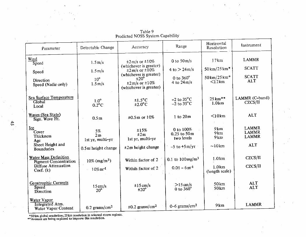
Table 9Predicted NOSS System Capability
HorizontalParameter Detectable Change Accuracy Range Resolution Instrument
WindSpeed 1.5m/s +2mis or +10% 0 to 50m/s 17kin LAMMR
(whichever is greater)Speed 1.5m/s +2m/s or +10% 4 to > 24m/s 50km/25km* SCATT
(whichever is greater)Direction 10° +20 ° 0 to 360° 50 km/25 km* SCATTSpeed (Nadir only) 1.5m/s -+2m/s or -+10% 4 to 24m/s <12 km ALT
(whichever is greater)
Sea Surface TemperatureGlobal 1.0° -+1.5°C -2 to 35°C 25 krn** LAMMR (C-band)Local 0.2°C -+2.0°C -2 to 35°C 1.0km CZCS[II
Waves(Sea State)Sign. Wave Hr. 0.5m +0.5m or 10% 1 to 20m <10km ALT
IceCover 5% -+15% 0 to 100% 9 km LAMMRThickness 2m -+2m 0.25 to 50m 9km LAMMRAge 1st yr, multi-yr 1st yr, multi-yr two levels 9 km LAMMRSheet Height andBoundaries 0.5mheight change +2m height change -5 to +5m/yr _10km ALT
Water Mass DefinitionPigment Concentration 10% (mg/m 3) Within factor of 2 0.1 to 100 mg/m3 1.0 km CZCS/IIDiffuse AttenuationCoef. (k) 10%m-1 Withih factor of 2 0.01 - 6m -1 1.0km CZCS/II
(length scale)
.Geostrophic CurrentsSpeed 15cm/s -+15cm/s > 15cm/s 50km ALTDirection 20° +20° 0 to 360 ° 50kin ALT
Water VaporIntegrated Atm.Water Vapor Content 0.2 grams/cm 2 -+0.2grams]cmz 0-6 grams/cm 2 9km LAMMR
*50 Irmaglobal resolution; 25km resolution in selected storm regions.**Avenues are being explored to improve this resolution.
pi
The ICEX sensor system contains the following six remote-sensing instruments:
Large Antenna Multifrequency Microwave Radiometer (LAMMR)
Wide Swath Imaging Radar (WSIR)
Scatterometer
Ice Elevation Altimeter System (IEAS), Radar
Ice Elevation Altimeter System (IEAS), Laser
Polar Ice Mapping Radiometer (PIMR)
The LAMMR is a passive multichannel radiometer which will measure the radiative brightness
temperature of the surface in seven microwave bands ranging from 1.4 GHz to 91 GHz (22.4 cm to
0.33 cm). The WSIR is an X-band (3 cm) synthetic-aperture, side-looking radar which produces
images of the surface with a pixel size of either 100 m over a 360 km wide swath or 25 m over a
90 km swath. The scatterometer, a side-looking radar, has the capacity to measure the scattering
cross section of surface irregularities at 14.6 GHz (2.05 cm). The IEAS is an altimeter which can
measure ice altitude profiles with two complementary instruments: a microwave radar, to provide
continuous coverage along the nadir track;and a laser ranging system with commandable pointing,
to provide precision altitude determination, off-axis mapping, fine-scale profile resolution, and
ranging to reflectors placed on the ice. The PIMR is a passive, 5-channel infrared radiometer (.4near,
infrared channels detecting reflected solar radiation and one thermal infrared channel at I l /_m),
which can map cloud cover, determine cloud parameters, measure surface temperatures, and aid in
distinguishing surface ice and snow from clouds.
A Data Collection and Location System (DCLS), for locating and relaying telemetry from
buoys and other in-situ platforms, is included in the spacecraft. It will use the ARGOS (or RAMS)
principle, in which periodic transmission from the platforms will be received and located by the
Doppler shift of the carrier as the satellite passes over the platform. _-
THE ICEX ORBIT
The orbit proposed for ICEX has an altitude of approximately 700 km and an inclination of
87° or 93°, so the spacecraft passes by the poles within 3 degrees of latitude. The altitude of-the
46
orbit is a compromise between the effects of atmospheric drag, area coverage and resolution require-
ments, and the transmitter power available from the active microwave sensors. The inclination is
determined primarily by the requirements imposed on the IEAS to measure the ice sheets of the
Antarctic. To encompass its most important areas, the nadir point of the spacecraft should approach
the South Pole to within approximately 3° of latitude, thus providing coverage of about 98 percent
of the continental area.
These selected orbit parameters apply even if the payload is carried on more than one space-
craft. In that case, all spacecraft must be placed in orbits having the same altitude and inclination
to provide compatible data from the imaging sensors (WSIR, LAMMR, scatterometer, and PIMR).
THE ICEX SPACECRAFT
The GSFC has performed a preliminary study for a dedicated spacecraft capable of carrying
the required sensors. The spacecraft selected for this study is an augmented Multimission Modular
Spacecraft (MMS). It is 3-axis stabilized and supports an expandable instrument module. The
design includes mission-unique equipment which meets all power, pointing, propulsion, and com-
munication requirements imposed by the mission and payload. The spacecraft would be launched
by Shuttle from the Western Test Range (WTR) and then flown into the ICEX orbit with the on-
board propulsion system. The propulsion system can be made large enough to return the spacecraft
to the Shuttle for service when required. The spacecraft is shown in Figure 17.
A proposed alternate spacecraft approach uses the NOSS placed into the ICEX orbit. This
approach requires that the NOSS LAMMR, scatterometer, and radar altimeter be modified to meet
ice measurement requirements, and that the laser altimeter and DCLS be added to the payload now
proposed for NOSS. A separate spacecraft is required to carry the WSIR and PIMR. No studies for
this spacecraft have been performed at this time,
47
SPACE SHUTTLE
From early in the 1980s, and at least throughout the following decade, the Shuttle will be
NASA's transportation system for access to space. Beyond that, the joint venture with Euro-
pean countries in developing the Spacelab will provide a functioning manned laboratory facility
in space. These two programs will play vital roles in the development of future remote sensors
(Allison et al., 1978). The four functional categories that these programs will provide are as
follows: (a) calibration of instruments on operational weather satellites, (b) direct monitoring of
slowly changing earth/atmosphere parameters, (c) development and demonstration of new remote
sensors, and (d) special experiments impossible or impractical by other means.
The difficulties inherent to calibration and correction for long-term drift of satellite instru-
ments have, in the past, presented manifold problems. First, logistic problems associated with
deployment of enough ground systems and interrelating their independent errors imposed severe
limitations. A second factor is that ground instruments do not generally measure the same
quantities as satellite instruments. For example, a satellite radiometer measures a TB integrated
over the entire scene in view, while ground truth data are restricted usually to point measure-
ments. Thus, at least calibrations of satellite instruments over their several years of useful life-
times and the ability to interrelate succeeding satellites, is a crucial requirement at least for the
emerging U.S. Climate Program. The Shuttle can fulfill this requirement by periodic flight of
instruments, calibrated against standards before and after flight, that can provide comparative
measurements at points of orbit conjunction with the satellites when identical scenes are in view.
Experience with the Nimbus-6 ERB instrument substantiates the desirability of continuing
total solar flux measurements at six-month intervals. Such measurements will provide an inde-
pendent and h_ghty calibrated set of data by themselves, but will also serve to interrelate the
total solar flux measurements of the ERBE instrumentation. Other parameters that can be
directly monitored by the Shuttle-Spacelab include a mmaber of the well mixed atmospheric
48
constituents, ozone, and tropospheric aerosols. For example, annual measurements are probably
adequate for CO2, CFMs, N20, NOx , and CH4 .
The Spacelab will also provide the needed facilities to develop, test, and demonstrate new
remote sensors. These include:
1. Sea Surface Temperature-Improvements that appear possible include increased signal-
to-noise ratios and additional wavelengths to reduce errors due to atmospheric water
vapor and clouds.
2. Vertical Temperature Profile-Accuracy of passive sounding below 20kin altitude can
beimproved with measurements at 4/zm and with bandwidths of 2 wave numbers.
Active Lidar promises even higher accuracy along with an order of magnitude-improved
vertical resolution.
3. Winds-Lidar techniques may be able to measure wind speed and direction in cloud-
free regions.
4. Stratospheric Aerosols-Stellar sources provide a large number of occultations not limited
to the ecliptic plane, so that reasonably good coverage of stratospheric aerosols is possible.
5. Tropospheric Aerosols-At present, no satellite technique exists for measuring tropospheric
aerosols, but a pulsed lidar system is believed to hold promise.
As plans are formulated for the development of these instruments (as well as any others
that may yet be identified) to the point where space flight development and testing can be
visualized, the advantages that Spacelab can provide will be capitalized up to the maximum
extent possible.
There are two particularly important special experiments in the area of remote sensing that
are especially suited to the Spacelab capabilities. These are extended cloud physics and radia-
tion studies and precipitation over land and water. In the case of the extended cloud and radia-
tion studies a group of instruments, including two separate radiometers and a lidar system, are
required. In the case of the precipitation studies, a microwave radiometer, a visible band radiom-
eter, an IR radiometer, and a 10cm radar are required. A number of short duration flights are
49
adequate to meet the objectives of both of these studies and the low orbiting Spacelab offers a
unique capability for their accomplishment.
REFERENCES
Allison, L. J. and E. A. Neil, 1962, Final report on the TIROS 1 meteorological satellite system,
NASA Tecnhcal Report R-131, Goddard Space Flight Center, Greenbelt, Md. 20771,
Allison, L. J., R. Wexler, C. R. Laughlin, and W. R. Bandeen, 1978, Remote sensing of the atmosphere
from environmental satellites, Special Technical Publication 653, American Society for Testing
and Materials, Philadelphia, Pa., pp. 83-155.
Brandli, H. W., 1976, Satellite Meteorology AWS-TR-76-264, Hq. Air Weather Service, U.S. Air
Force, Scott AFB, Illinois, p. 187.
Conlan, E. F., 1973, Operational products from the ITOS scanning radiometer data, NOAA TechniCal
Memo NESS 52, U.S. Dept. of Commerce, Washington, D. C.
Corbell, R. P., C. J. Callahan, and W. J. Kotsch, 1976, The GOES/SMS User's Guide, U.S. Dept. of
Commerce, NOAA, NESS, Washington, D.C., p. 118.
Curran, R. J., 1980, Satellite measurements of earth radiation budget for climate applications, Space
Shuttle: Dawn of an Era, Vol. 41, Advances in Aeronautical Sciences, American Astronautical
Society, San Diego, Calif.
Diesen, B. C., III and D. L. Reinke, 1978, Soviet meteor satellite imagery, Bulletin of the AmericanL
Meteorological Society, Vol. 59, No. 7, pp. 804-807.
Fortuna, J. J. and L. N. Hambrick, 1974, The operation of the NOAA polar satellite system, NOAA
Technical Memo NESS 60, U.S. Dept. of Commerce, NOAA, NESS, Washington, D.C.
50
Gloersen, P. and F. T. Barath, 1977, A scanning multichannel microwave radiometer for Nimbus--G
and Seasat-A, IEEE Journal of Oceanic Engineering, Vol. OE-2, No. 2, pp. 172-178.
Hirai, M., K. Watanabe, H. Tsuru, M. Miyaki, and M. Kimura, 1975, Development of geostationary
meteorological satellite (GMS) of Japan, Proc. of the Eleventh International Symposium on
Space Technology and Science, Tokyo, Japan, pp. 461-465.
Hussey, W. J., 1979, The TIROS-N/NOAA operational satellite system, U.S. Dept. of Commerce,
NOAA, NESS, Washington, D.C., p. 35.
Johnson, D.S., 1979, NOAA's operational satellite service, C3A, SignaljArmed Forces Communica-
tions and Electronics Assn., Falls Church, Va.
McClain, E. P., 1980, Passive radiometry of the ocean from space-an overview, Boundary Layer
Meteorology, Vol. 18, D. Reidel Pub. Co., Dordrecht, Holland, pp. 7-24.
Montgomery, H. and D. Endres, 1977, Survey of dwell sounding for VISSR atmospheric sounder
(VAS), NASA X-942-77-157, Goddard Space Flight Center, Greenbelt, Md., p. 85.
Morgan, J., 1978; Introduction to the meteosat system - Issue 1, MDMD]MET/JM-bd/833 European
Space Operations Centre, Darmstadt, Germany.
National Research Council, 1978, The global weather experiment-perspectives on its implementation
and exploration, Report of the FGGE Advisory Panel, National Academy of Sciences, Washington,
D.C., p. 104.
Nichols, D. A., 1975(a), DMSP Block-4 compendium, Space Division/YDE, U.S. Air Force; Air
Weather Service, Los Angeles, Calif.
Nichols, D.A., 1975(b), DMSP Block-5D compilation, Space Division/YDE, U.S. Air Force, Air
Weather Service, Los Angeles, Calif.
51
Nichols, D.A., 1976, DMSP Block-5A, B, C compendium, Space Division/YDE, U.S. Air Force, Aii_
Weather Service, Los Angeles, Calif.
NOAA Staff Members, 1977, NOAA program development plan for SEASAT-A research and applica-
tions, U.S. Dept. of Commerce, NOAA, NESS, Washington, D.C.
Press, H. and W. B. Huston, 1968, NIMBUS, a progress report, Astronautics and Aeronautics, March
1968, pp. 56-65.
Schwalb, A. and J. Gross, 1969, Vidicon data limitations, ESSA Technical Memo and NESC Teeh,
nical Memo 17, U.S. Dept. of Commerce, ESSA, NESC, Washington, D.C.
Schwalb. A., 1978, The TIROS-N/NOAA A-G satellite series, NOAA Technical Memo NESS 95,
U.S. Dept. of Commerce, NOAA, NESS, Washington, D.C., p. 75.
Staff Members, Goddard Space Flight Center, 1965, Observations from the Nimbus 1 meteoro-
logical satellite, NASA SP-89, Goddard Space Flight Center, Greenbelt, Md, 20771, p. 90;
Staff Members, Goddard Space Flight Center, 1976, Nimbus G, Nimbus observation processing
system, (NOPS) Design Study Report, Goddard Space Flight Center, Greenbelt, Md. 20771.
Staff Members, 1979(a), Concept for a Block 6 meteorological satellite system technical require-
ments document, Headquarters SAMSO/DMSP, U.S. Air Force, Air Weather Service,
Los Angeles, Calif.
Staff Members, 1979(b), ICEX, Ice and Climate Experiment, Goddard Space Flight Center,
Greenbelt, Md. 20771, p. 10.
Staff Members. 1980(a), Visible infrared spin-scan radiometer atmospheric sounder, system
description, Santa Barbara Research Center, Goleta, Calif.
r.,-3
Staff Members,1980(b),NationalOceanicSatelliteSystem(NOSS),Algorithm DevelopmentPlan,
Goddard Space Flight Center, Greenbelt, Md. 20771.
Suomi,V. E. and T. H. Vonder Haar, 1969, Geosynchronousmeteorologicalsatellite,Journal of
Spacecraftand Rockets, Vol.6, No. 3, pp. 342-344.
Vostreys, R. W. and R. Horowitz, 1979, Report on active and planned spacecraft and experi-
ments, NSSDC/WDC-A-R&S 79-03, National Space Science Data Center, Goddard Space
Flight Center, Greenbelt, Md. 20771.
53
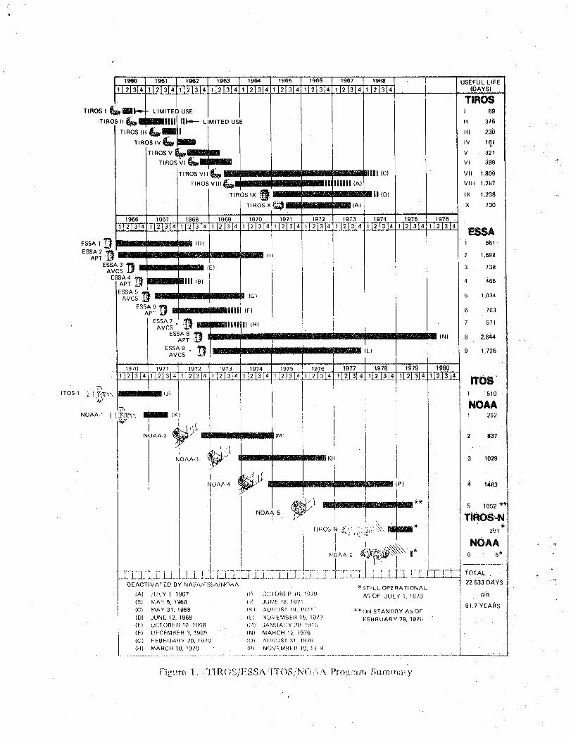
t
' 1960 19431 i 1962 '1963 1964 1966 1966 1967 !968 USEFUL LIFE
lJ 2131411J213 411 J21314 I121314 I121314 12[ZJ_&_zL[L3_ ) 2]zJ_4 i121314 , (DAYS)
J LIM TIROSTIROS I _lti illl ITED USE I 89
TIROS 11_R I _llilJ Ill-,.-- LIMITED USE I 376
T,.OS,,,t_.="_l] i ,,, 230T,.OS,V_i'mI I ,v 1_1
T,.OSV_lIUn I v 321! . v, 389
TiROsw__ ==J==i_ vii 1.8o9TIROSVll __ iHi|l (A) VIII 1.287
TIROS IX IX 1.238
X 730
1968 1969 1972 1973 1974 1976 1976
_112[314 1121314] ESSA
ESSA 1 D 1 861
ESSA 2APT " "' 2 1.692
ESSA 3 I_ (E) [ 3 738AVCSESSA 4 _
4 465
5 1.034
ESSA 6 _}APT 6 763
ESSA 7 . 7 571AVCS
ESSA 8 _ _ mR (N) 8 2,644APT
ESSA 9 . _1_ (L) 9 1.726AVCS
1970 I 19 1979
ITO$_TOS-1l i_:'_UU_ _ 510
NOAA-1_ _'_'T__ (K_ 1 262/
/._' "_
NOAA--2 . t.;,- 2 837
NOAA 3 3 1029
NOAA4 (P) # 1463t
,_,..q.'_.... __ -_____ ...._**._ .,/ 5 10.52 '_1
' TIROS,-Ni " " 41-
{,_c__;,"..X."_. _ * 261
_Jo,_,A-6t4_._;,_, I" | 6 s*, | , _1" I /
;L--_;;_EII-L-;L];_-];.L;;L-L;;L;.ZTL[.L;i;Zq_I£LLr_Z_I.;L;T.._;-LTL._L;__£-£;L-EZ_-_"tOTaL:.DEACTIV/_TED BY NASA/t: SSA.iNOAA "<'ST_LL OPERATIONAl.It 22,533 DAY_
(A) JULY 1 1967 Ill ',)C[OB[-F + N;, f.q7!) AS OF JULY 1. 1979 OR
(B) I,,',&Y 5, 1968 la JUN[ !6 1971 61 7 YE,ARSJ (C) MAY31, 1968 !KI _,UGIIS 'r 19 197! _"*or.,ISTANI)BYASOF
j (D) JUNE 12, 1968 tL NOVEMBER 16, 1913 FEBRUARY 28 1979(E) UCrOBER I( 19138 N.I} JANUAIY ?O !t7_'_'.5 " " "(F) [)FCFMBER 3, '_969 IN) MARCH 12, i976
(O) FEBRUAHY 20, 1910 [OI ,",,UGUS1 3!, 1976
I- MARCH 10, !970 P) NOV£MBER 1[;, [:_8 [
"'_" , "_." / ?C'(. _t _g_.tre, 1 TIRC_'o,I,+_.,/\"IT(I),£,"N()i'+,'\. F':t"o+.'+:+'_P;lSt,hl,,rrl+t+y
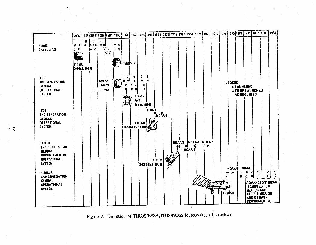
TIROSSATELLITES
"IROSI
TOS 9O
tST GENERATION LEGENDGLOBAL AVCS 8 • LAUNCHEDOPERATIONAL (FEB.1966) • o TO BE LAUNCHEDSYSTEM AS REQUIRED
"" (FEB.1966)
J0 'ITOS ITOS-12NO GENERATION • •ZNOAA-1
GLOBAL
OPERATIONAL TI M_J_ SYSTEM (JANUARY 1970)L/'=
I|
ITOS-O ' NOAA.-4 NOAA-5t
2NOGENERATION , •GLOBAL NOAA-3ENVIRONMENTAL
OPERATIONAL ITOS-DSYSTEM (OCTOBER1972}
NOAA-6 NOAATIROS-N o o3RD GENERATION B E
GLOBAL ADVANCEDTI ROS-NOPERATIONAL (EQUIPPEDFORSYSTEM SEARCHAND
RESCUEMISSIONAND GROWTH
Figure 2. Evolution of TIROS/ESSA/ITOS/NOSS Meteorological Satellites
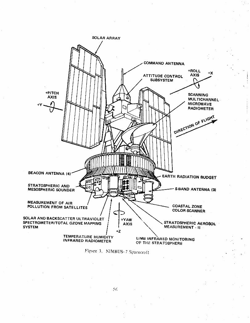
SOLAR ARRAY
COMMAND ANTENNA.
+ROLL
ATTITUDE CONTROL AXIS +XSUBSYSTEM
+PITCH SCANNINGAXIS MULTICHANNEL
+y _ MICROWAVERADIOMETER
BEACON ANTENNA EARTH RADIATION BUDGET
STRATOSPHERIC ANDMESOSPHERIC SOUNDER S-BAND ANTENNA (3)
MEASUREMENT OF AIRPOLLUTION FROM SATELLITES COASTAL ZONE
COLOR SCANNER
SOLAR AND BACKSCATTER ULTRAVIOLET +YAWSPECTROMETER/TOTAL OZONE MAPPING AXiS X_ STRATOSPHERIC AEROSOL,
SYSTEM _ MEASUREMENT .. II+Z
TEMPERATURE HUMIDITY LiMB INFRARED MONITORINGINFRARED RADIOMETER OF THE STRATOSPHERE
Fi_.ure 3. N,MBUS-..7Spacecrall
5(,
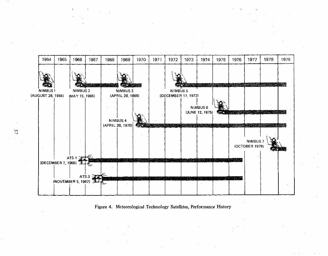
(OCTOBER 1978)
(DECEMBER 7, 1966)
Figure 4. Meteorological Technology Satellites, Performance History
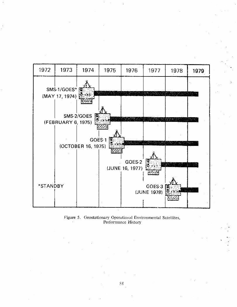
' " '1979 11972 1973 1974 1975 1976 1977 1978
SMS-1/GOES* _=::;.21____ i(MAY 17, 1974)
SMS-2/GOES . r:i:;i:i: __ ll_immm_
(FEBRUARY 6, 1975)
GOES-1 _';._iL:':'::-'mmmmm___mmm(OCTOBER 16, 1975) _"
GOES-2 ___,._:_i€T._m/mmmmmm(JUNE 16, 1977)
*STANDBY GOES-3 ;_-×::'
(JUNE 1978) _=.,,.::...,
Figure 5. Geostationary Operational Environmental Satellites,Performance History
,1.._
58
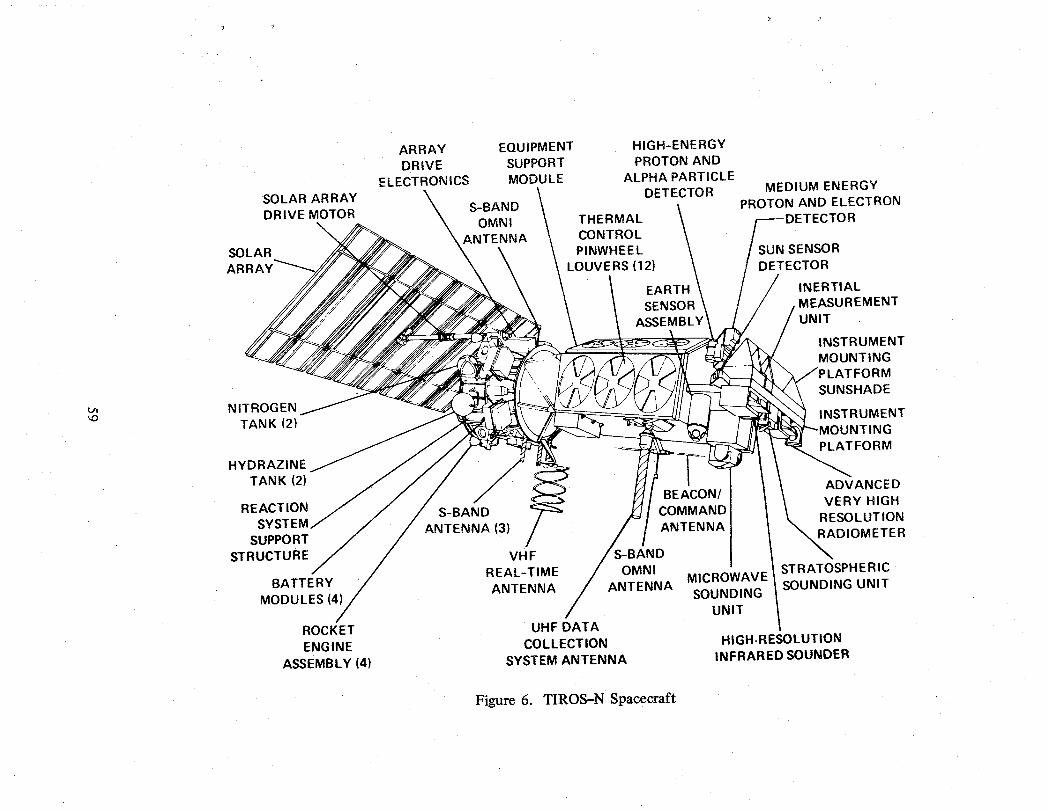
ARRAY EQUIPMENT HIGH-ENE RGYDRIVE SUPPORT PROTON AND
ELECTRONICS MODULE ALPHA PARTICLE MEDIUM ENERGYSOLAR ARRAY \ \
DETECTOR
k_ ! PROTON AND ELECTRON
DRIVE MOTOR S-BAND
._ OMNI THERMAL \ sDETECTORANTENNA CONTROL \SOLAR PINWHEEL . SUN SENSOR
AI LOUVERS (12) \ DETECTOR
EARTH \ // INERTIALSENSOR \ MEASUREMENT
ASSEMBLY / UNIT
INSTRUMENTMOUNTING
ATFORMSUNSHADE
N ITROG EN INSTR UMENT"_ TANK (2) )UNTING
PLATFORM
HYDRAZINE
TANK (2) ADVANCED.,/ BEACON/ VERY HIGH
REACTION S-BAND COMMAND RESOLUTION
SYSTEM ANTENNA (3) / ANTENNASUPPORT , )METERSTRUCTURE VH F _AND
REAL-TIME OMNIBATTERY ANTENNA ANTENNA MICROWAVE I
STRATOSPHERIC
SOUNDING t SOUNDING UNITMODULES (4)// UNIT I
/
ROCKET UHF DATAENGINE COLLECTION HIGH-RESOLUTION
ASSEMBLY (4) SYSTEM ANTENNA INFRARED SOUNDER
Figure 6. TIROS-N Spacecraft

THERMAL CONTROL PINWHEEL LOUVERS (16) SAR
- - h V
REA (4)
Figure 7. Advanced TIROS-N Spacecraft
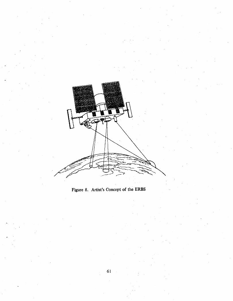
\\\
Figure 8. Artist's Concept of the ERBS
61
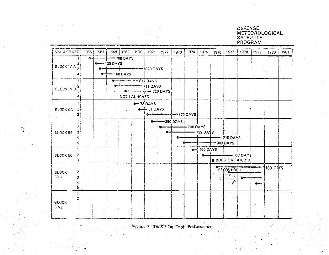
DEFENSE METEOROLOGICAL SATELLITE
Figure 9. -DIkiSP On-Orbit 2erformance
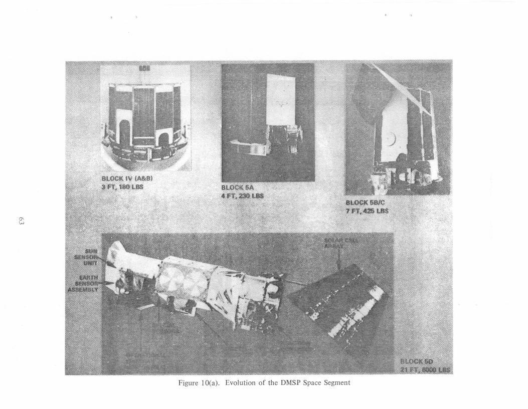
Figure 10(a). Evolution of the DMSP Space Segment
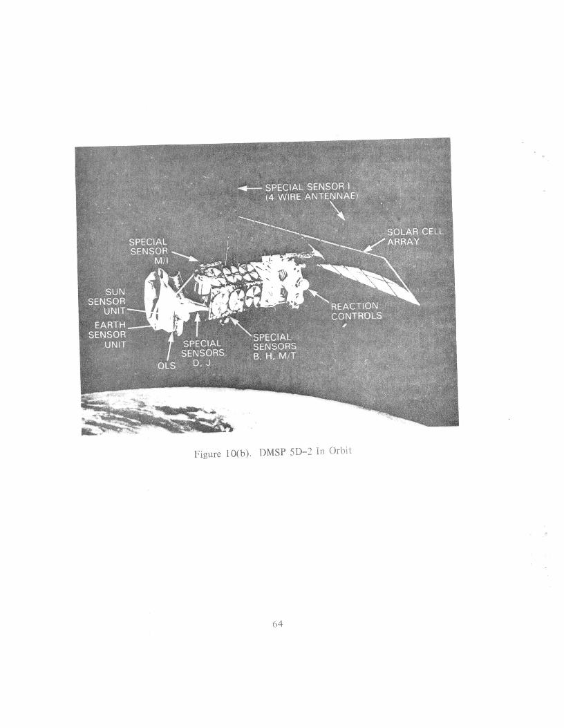
L
Figure 10(b). DMSP 5D-2 In Orbit
64
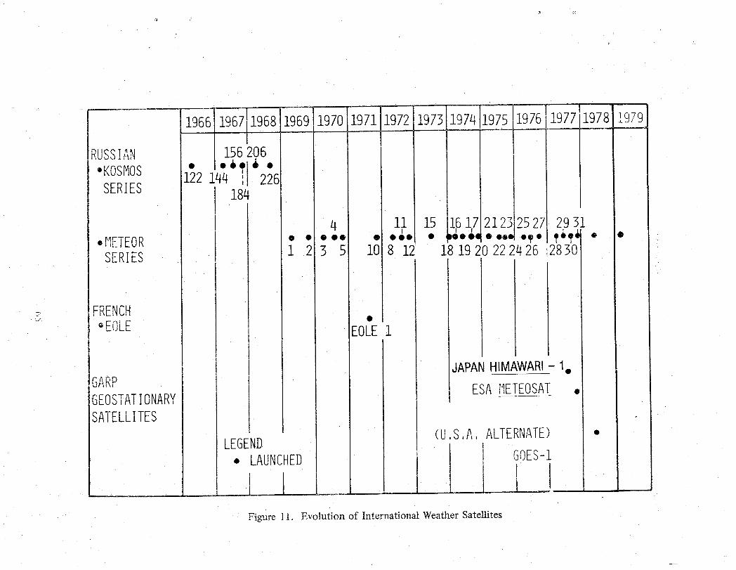
1966 1968.9691970197] 1976
RUSSIAN I156206' . Io6ol_, •
•KOSMOS 122144 il 226SERIES 184
4 ii 15 1617212 252; 2931oIIETEOR • o .o., °&. • ,,,o.,°o..lo_. I.,_,i,_• I"SERIES 1 2 3 51 8 12 1819 222426 2830 I
_- FRENCH , o " I_" _EOLE EOLE1
IJAPANH!MAVVABI- •
GARP ESA_T_ /
GEOSTATIONARY °
SATELLITES i ] -
(U.S.A,ALTERNATE) ° I
LEGEND I i iOE
S-• LAUNCHEDI
Figure ! 1. Evolution of Internationai Weather Satellites
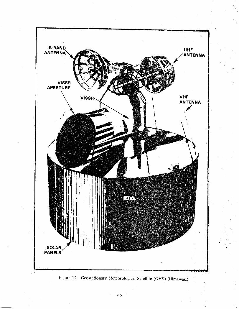
8-BAND UHF
ANTEN ,fANTENNA#
_J
VISSRAPERTURE
\
\\ VlS_ VHFANTENNA
,/
i
lj tSOLARPAN ELS
Figure 12. Geostationary Meteorological Satellite (GMS) (Himawari)
66
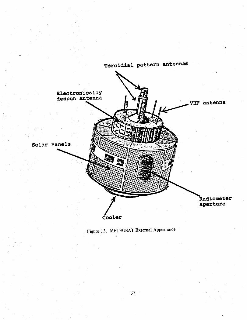
Toroidial pattern antennas
Electronicallydespun antenna
V_F antenna
Solar Panels
Radiometer
aperture
Cooler
Figure 13, METEOSAT External Appearance
67
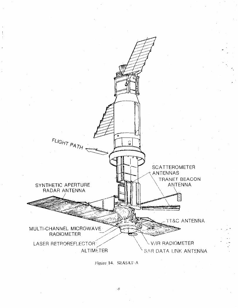
SCATTEROMETERANTENNAS
TRANET BEACONSYNTHETIC APERTURE \\ ANTENNA
RADAR ANTENNA \"/ \
"l'l"&C ANTENNA
MULTI-CHANNEL MICROWAVERADIOMETER 7 !"
.J/' j// \
- \ dR RADIOMETER -_LASER RETROREFLECTOR ./ \ALTIMETER \ S_',RDATA [.INK ANTENNA
f,'igure 14. S}::Ac_ATo.A
:.R
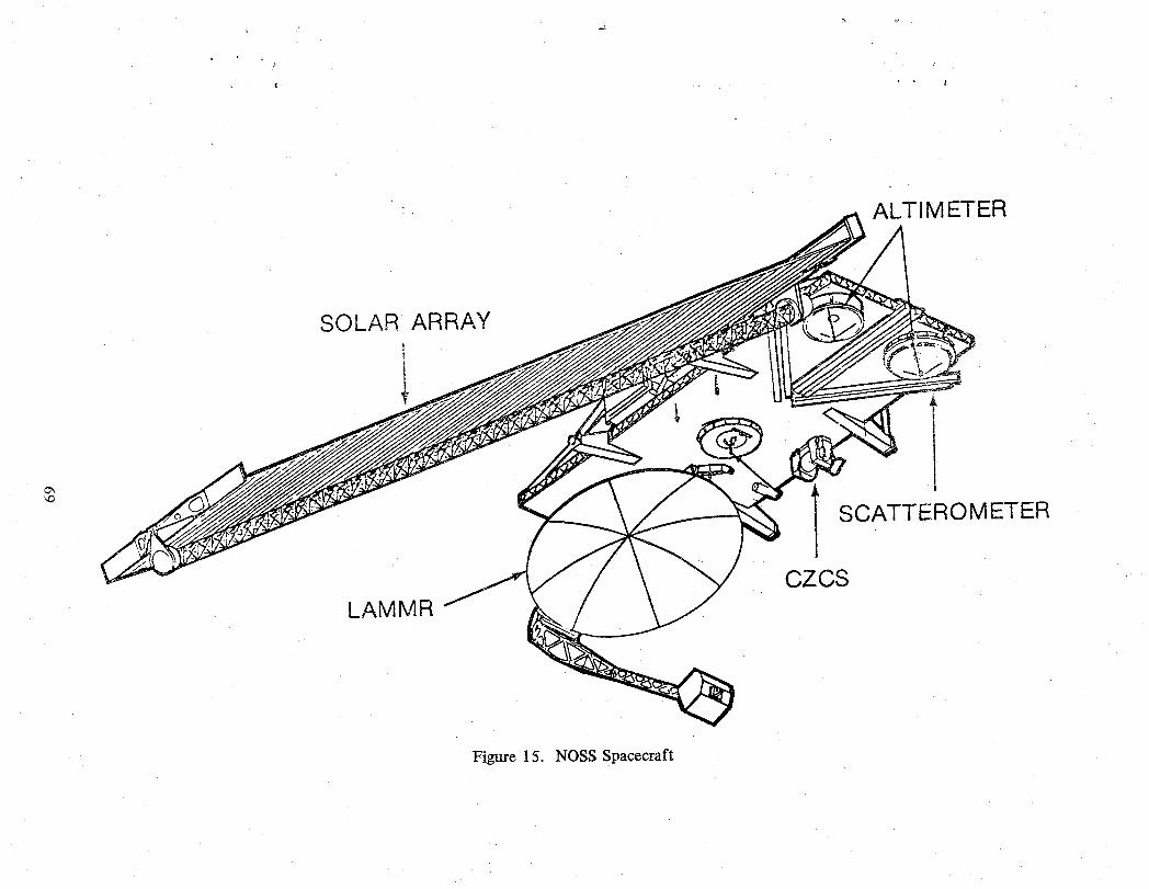
-. ALTIMETER
SOLAR ARRAYi
SCATTEROMETER
CZCSLAMMR
Figure 15. NOSS Spacecraft
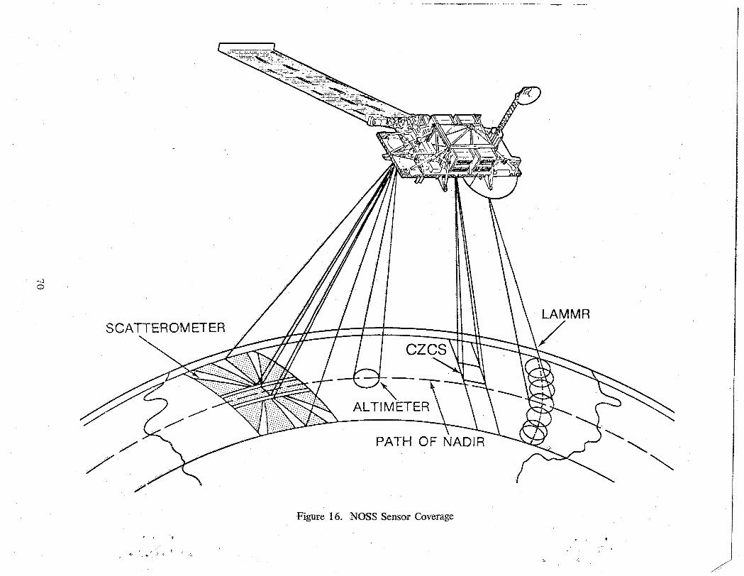
SCATTEROMETER
Figure 16. NOSS Sensor Coverage
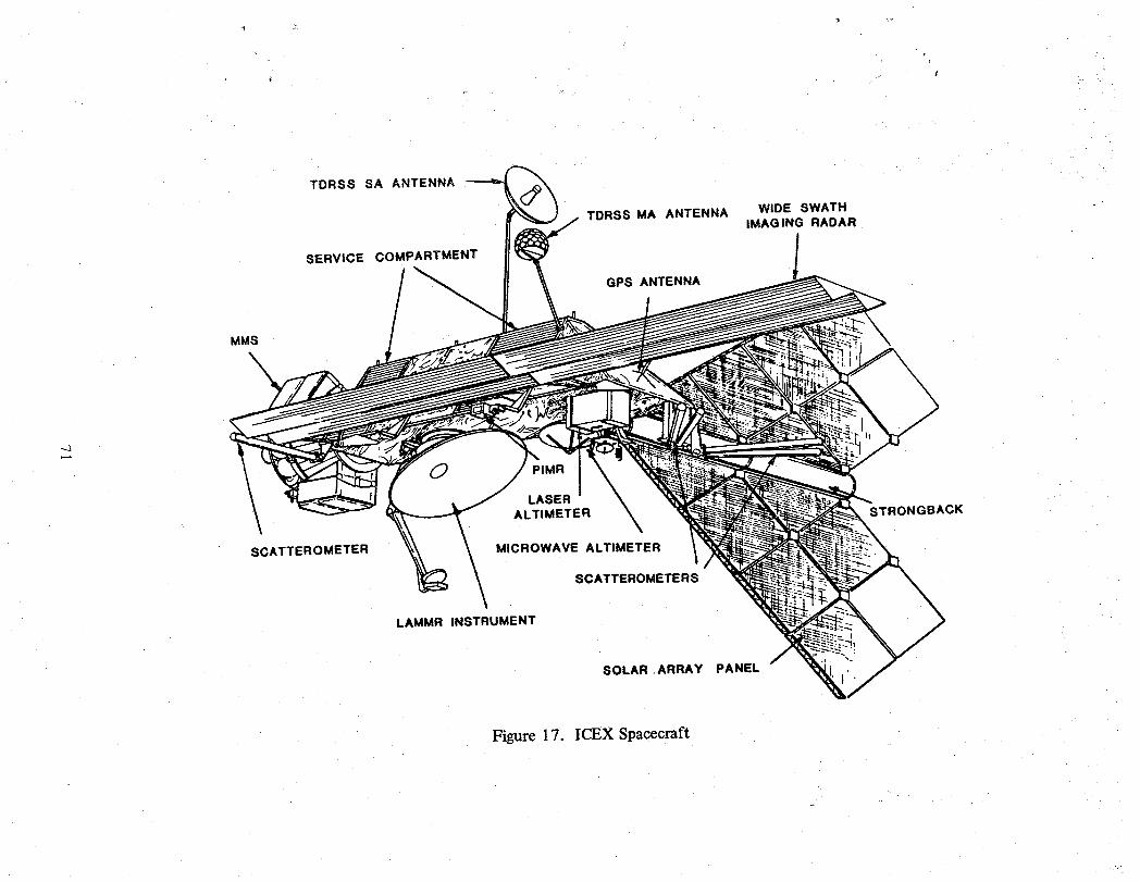
TDRSS SA ANTENNA
TDRSS MA ANTENNA WIDE SWATHIMAGING RADAR
SERVICE COMPARTMENT
GPS ANTENNA
MMS
OLASER
ALTIMETER ;BACK
SCATTEROMETER MICROWAVE ALTIMETER
SCATTEROMETERS
LAMMR INSTRUMENT
.z --
SOLAR .ARRAY PANEL
Figure 17. ICEX Spacecraft

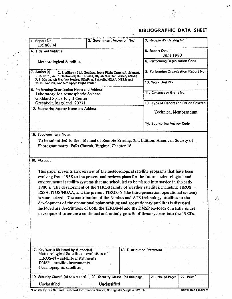
BIBLIOGRAPHIC DATA SHEET
1. ReportNo. 2. GovernmentAccessionNo. 3. Recipient'sCatalogNo.TM 80704
t ' "
4. Title and Subtitle 5. Report Date '- June 1980
MeteorologicalSatellites 6. PerformingOrganizationCode
7. Author(s) L. L Allison(Ed.),GoddaxdSpace Flight Center;A. Schnapf, 8. Performing Organization Report No.RCACorp.,Astro-Electronics;B.C. Diesen,III, AirWeatherService,USAF;
" P.S. Martin,AirWeatherService,USAF;A. Schwalb,NOAA,NESS; andW.R. Bandeen,GoddardSpaceFlightCenter 10. Work Unit No.
9. PerformingOrganizationName andAddress , ,Laboratory for Atmospheric Science 11. ContractorGrant No.Goddard SpaceFlight CenterGreenbelt, Maryland 20771 13. Type of Report and Period Covered
12. Sponsoring Agency Nameand AddressTechnicalMemorandum
14. SponsoringAgencyCode
15. SupplementaryNotes
To be submitted to the: Manual of Remote Sensing, 2nd Edition, American Society of/
Photogrammetry, FallsChurch, Virginia,Chapter 16
16. Abstract
This paper presents an overview of the meteorological satellite programs that have beenevolvingfrom 1958 to the present and reviewsplans for the future meteorologicalandenvironmental satellitesystemsthat are scheduledto be placed into servicein the early1980's. The development of the TIROS family of weather satellites, including TIROS,ESSA, ITOS/NOAA, and the present TIROS-N (the third-generation operational system)is summarized. The contribution of the Nimbusand ATStechnology satellitesto thedevelopment of the operational polar-orbiting and geostationary satellites is discussed.Included are descriptions of both the TIROS-N and the DMSP payloads currently underdevelopmentto assurea continued and orderly growthof these systemsinto the 1980's.
17. Key Words(Selectedby Author(s)) 18. DistributionStatementMeteorologicalSatellites- evolutionofTIROS-N - satelliteinstrumentsDMSP- satellite instrumentsOceanographic satellites
19. SecurityClassif. (of this report) 20. SecurityClassif.(of thispage) 21. No. of Pages 22. Price*
Unclassified UnclassifiedJ
*For sale by the National Technical Information Service, Springfield, Virginia 22151. OSFC 25-44 [10/77


_JItlSlS_tllII_iiiiii_llll_llllllJllSf3 1176 01444 4542
,€_ _. _.,_


![Inula Bollard LED Solar [IBLS] selux · LED Light Engine Distribution Guide ... FLAT WASHER CONCRETE 1 1/2" [38.1mm] 3" ... Inula Bollard LED Solar Light_Columns_&_Wall_Wconces/Inula_Bollard_LED_Solar_.zip](https://img.pdfslide.us/doc/110x75/5acba7967f8b9a27628b901a/inula-bollard-led-solar-ibls-light-engine-distribution-guide-flat-washer-concrete.jpg)