Embed Size (px)
Citation preview

I _¸
NASA
Technical Memorandum 106696
t,e ....V/<_70
Army Research Laboratory
Technical Report ARL-TR-573
Computerized Design and Generation ofLow-Noise Helical Gears With
eX_
M difi d S fa Top 1 gy °o e ur ce o oI
tt_ct,Z
EL. Litvin, N.X. Chen,and J. Lu
University of Illinois at ChicagoChicage, Illinois
R.E Handschuh
Vehicle Propulsion Directorate
U.S. Army Research LaboratoryLewis Research Center
Cleveland, Ohio
Prepared for the23rd Mechanisms Conference
sponsored by the American Society of Mechanical EngineersMinneapolis, Minnesota, September 11-14, 1994
0m ?,..
•-, o,,t_ ,._e- oD o
t,¢3
National Aeronautics and
Space Administration
U.S. ARMY
RESEARCH LABORATORY
https://ntrs.nasa.gov/search.jsp?R=19950006670 2019-05-01T10:01:35+00:00Z


Computerized Design and Generation of Low-Noise
Helical Gears With Modified Surface Topology
F.L. Litvin, N.X. Chen, and J. Lu
University of Illinois at ChicagoDepartment of Mechanical Engineering
Chicago, Illinois 60616
R.F. Handschuh
Vehicle Propulsion DirectorateU.S. Army Research Laboratory
Lewis Research Center
Cleveland, Ohio 44135
Abstract
An approach for design and generation of low-noise helical gears with localized bearing
contact is proposed. The approach is applied to double circular arc helical gears and modified
involute helical gears. The reduction of noise and vibration is achieved by application of a
predesigned parabolic function of transmission errors that is able to absorb a discontinuous
linear function of transmission errors caused by misalignment. The localization of the bearing
contact is achieved by the mismatch of pinion-gear tooth surfaces. Computerized simulation
of meshing and contact of the designed gears demonstrated that the proposed approach
will produce a pair of gears that has a parabolic transmission error function even when
misalignment is present. Numerical examples for illustration of the developed approach are
given.
a
b
L_
M_j
N,.
P
ri
rwp
r_,r*
3_3r
u(J) ,/,(_)
v(iJ)
CI_n
AE
A%,A%
A¢2, A¢2
P_
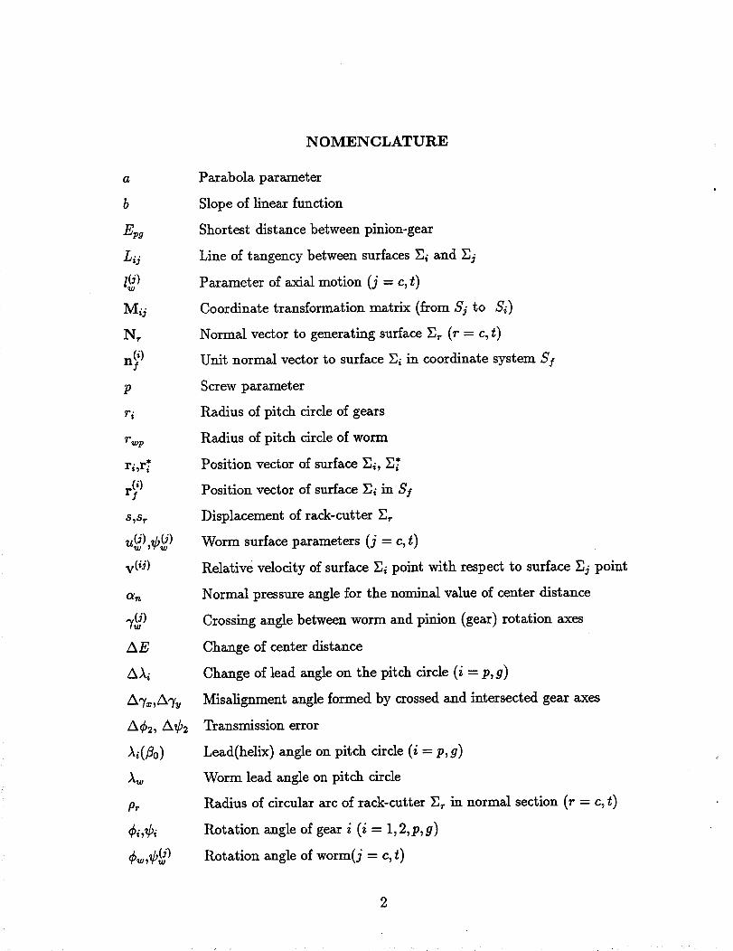
NOMENCLATURE
Parabola parameter
Slope of linear function
Shortest distance between pinion-gear
Line of tangency between surfaces _i and _j
Parameter of axial motion (j = c, t)
Coordinate transformation matrix (from Sj to Si)
Normal vector to generating surface _ (r = c, t)
Unit normal vector to surface 2i in coordinate system Sf
Screw parameter
Radius of pitch circle of gears
Radius of pitch circle of worm
Position vector of surface _i, _*
Position vector of surface Ei in Sf
Displacement of rack-cutter _
Worm surface parameters (j = c, t)
Relative velocity of surface _i point with respect to surface _j point
Normal pressure angle for the nominal value of center distance
Crossing angle between worm and pinion (gear) rotation axes
Change of center distance
Change of lead angle on the pitch circle (i = p, g)
Misalignment angle formed by crossed and intersected gear axes
Transmission error
Lead(helix) angle on pitch circle (i = p,g)
Worm lead angle on pitch circle
Radius of circular arc of rack-cutter _ in normal section (r = c, t)
Rotation angle of gear i (i = 1,2,p,g)
Rotation angle of worm(j = c, t)

1. INTRODUCTION
In the study to be conducted in this paper two types of helical gears that transform
rotation between parallel axes are considered: (i) double circular arc helical gears(Novikov-
Wildhaber gears) with modified topology, and (ii) involute helical gears with modified topol-
ogy. An approach for the design and generation of both types of helical gears is proposed in
this paper. This approach enables one to reduce the level of noise, avoid edge contact, and
provide a stable bearing contact.
The circular arc helical gears (N.-W.) have been proposed by Novikov [1] and Wildhaber
[2]. However, there is a significant difference between the ideas proposed by the above
inventors. Wildhaber's idea is based on generation of the gears by the same imaginary rack-
cutter that provides conjugate gear tooth surfaces being in l/he contact at every instant.
Novikov proposed the application of two mismatched imaginary rack-cutters that provide
conjugate gear tooth surfaces being in point contact at every instant. The great advantage of
Novikov's invention is the possibility to obtain a small value of the relative normal curvature
and reduce substantially the contact stresses. The weak point of Novikov's idea was the high
value of bending stresses since the gear tooth surfaces are in point contact at every instant.
The successful manufacturing of N.-W. gears has been accomplished by application of two
mating hobs based on the idea of two mating imaginary rack-cutters. This idea has been
proposed by Kudrjavtsev [3] in the former USSR and Winter and Looman [4] in Germany.
Circular arc helical gears are only a particular case of a general type of helical gears
which can transform rotation with constant gear ratio and axe in point contact at every
instant. Litvin [5] and Davidov [6] simultaneously and independently proposed a method of
generation for helical gears by "two rigidly connected" tool surfaces. According to this idea,
the generating surfaces may be rack-cutter surfaces, particularly.
The kinematics of single circular arc helical gears was the subject of the paper by Litvin
and C.-B. Tsay [7].
3
A substantial step forward in the design of N.-W. gears was the development of double
circular arc helical gears with two zones of meshing. Such gears have been proposed in the
former USSR [8] and the People's Republic of China [9]. The geometry of such gears was
discussed in [10]. The main advantage of this development is the possibility to reduce the
bending stresses keeping the advantage of reduced contact stresses.
A great disadvantage of N.-W. gears, even with two zones of contact, is their noise. The
investigation performed by the authors of this paper shows that the noise results from the
unfavorable shape of the function of transmission errors of misaligned gear drives (fig. 1).
The function of such transmission errors is piecewise, almost linear, and has the frequency
of a cycle of meshing of one pair of teeth. These transmission errors cause high vibration
and noise, and therefore such transmission errors must be avoided.
Conventional helical involute gears are designed for transformation of rotation between
parallel axes. Theoretically, the gear tooth surfaces are in line tangency at every instant,
along a straight line that is a tangent to the helix on the gear base cylinder. However, the
line contact of gear tooth surfaces can be realized only for an ideal gear drive: In reality,
the crossing or intersection of axes of rotation (instead of being parallel) and errors of lead
angle result in the so-called edge contact, a specific instantaneous point contact caused by
curve-to-surface tangency. Here, the curve is the edge of the tooth surface of one of the
mating gears and the surface is the tooth surface of the other one.
In trying to avoid edge contact, manufacturers of helical gears used various methods of
crowning (deviation) of the gear tooth surfaces. However, the methods of crowning applied
have not been complemented with the analysis of transmission errors caused by misalignment.
The investigation conducted in this study shows that improper crowning may allow edge
contact to be avoided, but cannot avoid the appearance of transmission errors of the shape
shown in fig. 1 (b).
In this paper a modified topology of low-noise N.-W. gears and involute helical gears are
4

proposed that satisfy the following requirements:
(1) The noise and vibration of both types of gears can be reduced substantially by
application of a predesigned function of transmission errors of a parabolic type [11-13]. It was
shown that such a predesigned function can absorb an almost linear function of transmission
error, such as shown in fig. l(b), caused by misalignment.
(2) The bearing contact is localized. Theoretically, the tooth surfaces of N.-W. gears are
in tangency at every instant at two points without misalignment and at one point when the
gears are misaligned. However, the two-zone contact is restored under a load due to the
deflection of gear teeth. The tooth surfaces of modified helical gears are in point contact at
every instant instead of line contact. The instantaneous contact of gear tooth surfaces at
a point is spread over an elliptical area due to dastic deformation of the gear teeth. The
dimensions of the instantaneous contact ellipse can be controlled in both cases by choosing
proper design parameters.
(3) The proposed gear tooth surfaces can be ground (or cut) by a worm (hob) designed
for generation of the pinion (gear). For the manufacture of the gear, the relation between the
rotational motions of the gear and cutting tool is nonlinear. This can be accomplished by
the application of a Computer Numerically Controlled (CNC) machine such as a Reishauer
machine [14]. For the pinion, conventional manufacturing machines can be used since the
relation between the rotational mations of the pinion and the cutting tool is linear.
The developed approach is based on the following ideas:
(1) Two imaginary rigidly connected rack-cutters for conjugation of gear tooth surfaces
with the new topology are applied. The generated gear tooth surfaces are in point contact,
and a parabolic function of transmission errors is provided.
(2) The real manufacturing of pinion-gear tooth surfaces is accomplished by a grinding
worm (hob). The worm surface is an envelope to the family of surfaces of the imaginary
rack-cutter. The pinion (gear) tooth surface is an envelope to the two parameter family of
5

worm surfaces.
(3) The meshing and contact of pinion-gear tooth surfaces of a misaligned gear drive are
computerized and the influence of assembly errors is investigated. An analytical approach
for determination of transmission errors caused by misalignment will be described.
2. INTERACTION OF PARABOLIC AND LINEAR FUNCTIONS OF
TRANSMISSION ERRORS
Ni and the ideal trans-Ideal gears transform rotation with constant gear ratio m2i =
mission function is
N1¢_(¢_) = _-_2¢1 (1)
where Ni and N_ are the numbers of gear teeth.
However, the crossing or intersection of gear axes (instead of being parallel), and errors of
lead angle cause a transmission function 42(41) that is shown in fig. l(a). In the investigation
to be presented (see sections 7 and 8) is that the function of transmission errors caused by the
errors of misalignment mentioned above is a piecewise, almost linear function of transmission
errors A¢2(¢1) with the frequency of a cycle of meshing for one pair of teeth (fig. l(b)).
Here:
N1a4 (¢1) = - G¢, (2)
Transmission errors of this type cause a discontinuity of the driven gear angular velocity
at transfer points (when one pair of teeth is changed to another one), and vibration and
noise become inevitable.
It has been shown [11-13] that a predesigned parabolic function of transmission errors
(fig. 2) interacting with a linear function will keep to be a parabolic function with the same
parabola parameter. A parabolic function of transmission errors is much more preferable
6
than a linear function since the transmission function of the driven gear will be a continuous
one and the stroke at the transfer point will be reduced substantially.
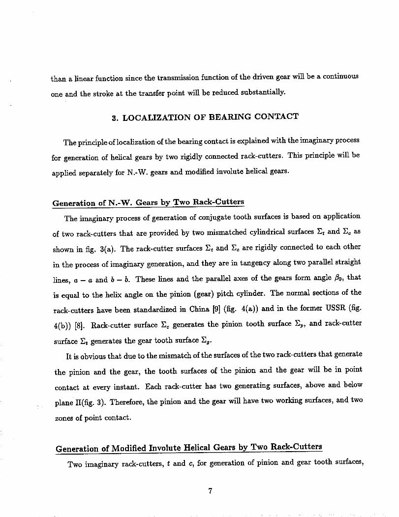
3. LOCALIZATION OF BEARING CONTACT
The principle of localization of the bearing contact is explained with the imaginary process
for generation of helical gears by two rigidly connected rack-cutters. This principle will be
applied separately for N.-W. gears and modified involute helical gears.
Generation of N.-W. Gears by Two Pmck-Cutters
The imaginary process of generation of conjugate tooth surfaces is based on application
of two rack-cutters that are provided by two mismatched cylindrical surfaces Et and Ec as
shown in fig. 3(a). The rack-cutter surfaces Et and Ec are rigidly connected to each other
in the process of imaginary generation, and they are in tangency along two parallel straight
lines, a - a and b - b. These lines and the parallel axes of the gears form angle rio, that
is equal to the helix angle on the pinion (gear) pitch cylinder. The normal sections of the
rack-cutters have been standardized in China [9] (fig. 4(a)) and in the former USSR (fig.
4(b)) [8]. Rack-cutter surface _]_ generates the pinion tooth surface Ep, and rack-cutter
surface E_ generates the gear tooth surface _]9.
It is obvious that due to the mismatch of the surfaces of the two rack-cutters that generate
the pinion and the gear, the tooth surfaces of the pinion and the gear will be in point
contact at every instant. Each rack-cutter has two generating surfaces, above and below
plane II(fig. 3). Therefore, the pinion and the gear will have two working surfaces, and two
zones of point contact.
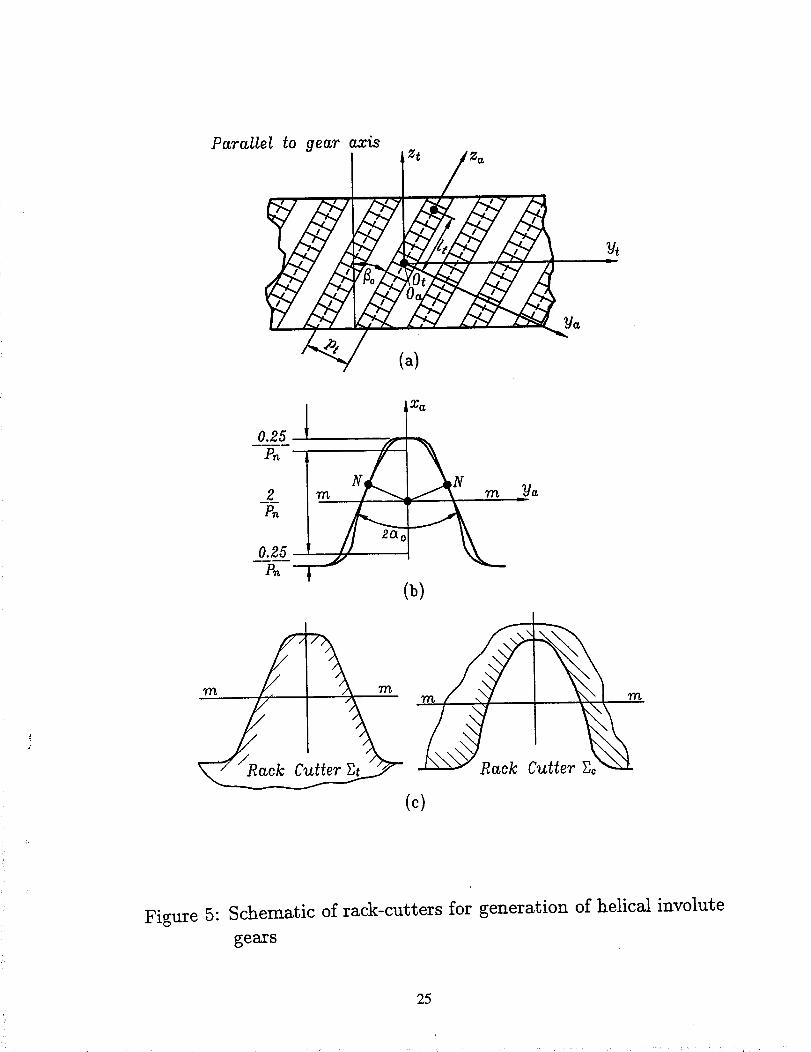
Generation of Modified Involute Helical Gears by Two Rack-Cutters
Two imaginary rack-cutters, t and c, for generation of pinion and gear tooth surfaces,

respectively, are applied in this case as well. The rack-cutter t that generates the gear tooth
surface is provided by plane _]t, and rack-cutter c designed for the generation of the pinion
is provided by cylindrical surface _c that differs slightly from plane _(fig. 5(b)). The rack-
cutter surfaces _t and _c are rigidly connected each to other in the process of the imaginary
generation, and they are in tangency along a straight line that is parallel to axis za and
passes through point N(figs. 5(a) and (b)). This line and the parallel axes of the gears form
angle rio, that is equal to the helix angle on the pinion (gear) pitch cylinder. The normal
sections of the rack-cutters are shown in figs. 5(b) and (c)). The generated pinion-gear tooth
surfaces are in point contact at every instant, and there is only one zone of meshing. (Recall
that N.-W. gears have two zones of meshing.)
4. GENERATION OF CONJUGATE PINION AND GEAR TOOTH
SURFACES BY TWO IMAGINARY RACK-CUTTERS
Schematic of Generation
Coordinate systems used for the process of generation of the pinion(gear) tooth surfaces
by rack-cutters are shown in fig. 6. The fixed coordinate systems S,_ and S_ are rigidly
connected to the frame of the cutting machines that are used for generation of the pinion
and the gear, respectively. Movable coordinate systems S_(r = c,t), S_ and S9 are rigidly
connected to the rack-cutters, the pinion and the gear, respectively.
The rack-cutter surface _ (r = t, c) is represented in S_ by the equation
where u_ and 0_ are the surface parameters.
The unit normal to the rack-cutter surface is represented as
(3)
N_ ar_ cgr_ (4)
8
SurfacesSt and _c of the rack-cutters have the same direction and orientation of teeth
determined by _0.
The installment of the rack-cutters shown in fig. 6 provide: (i1 direction of pinion teeth
that is opposite to the direction of teeth of rack-cutter c (fig. 6(a)), and (ii) direction of gear
teeth that is the same as of rack-cutter t (fig. 6(b)).
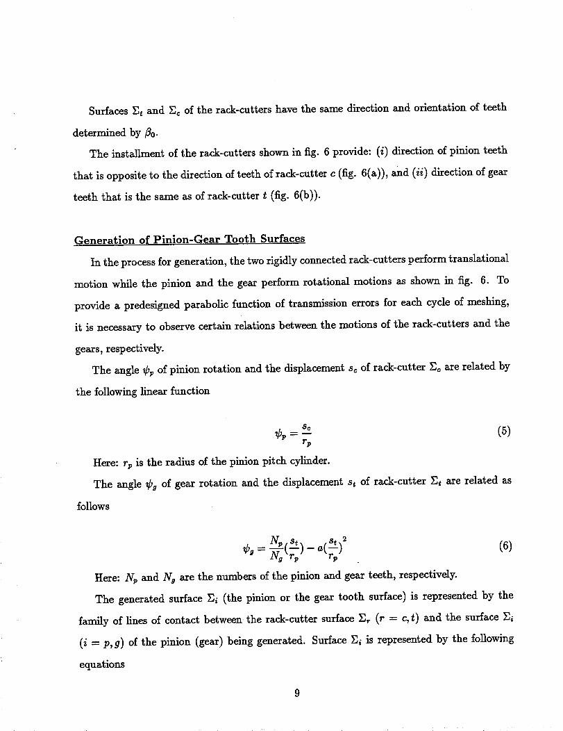
Generation of Pinion-Gear Tooth Surfaces
In the process for generation, the two rigidly connected rack-cutters perform translational
motion while the pinion and the gear perform rotational motions as shown in fig. 6. To
provide a predesigned parabolic function of transmission errors for each cycle of meshing,
it is necessary to observe certain relations between the motions of the rack-cutters and the
gears, respectively.
The angle Cp of pinion rotation and the displacement sc of rack-cutter _c are related by
the following linear function
= (5)r_
Here: r v is the radius of the pinion pitch cylinder.
The angle Ca of gear rotation and the displacement st of rack-cutter _t are related as
follows
2 (6)Cg= Yg'r "
Here: Np and N a are the numbers of the pinion and gear teeth, respectively.
The generated surface _ (the pinion or the gear tooth surface) is represented by the
family of lines of contact between the rack-cutter surface _ (r = c,t) and the surface _i
(i = p, g) of the pinion (gear) being generated. Surface _ is represented by the fonowing
equations
9

(7)
Ori Ori Ori.
•(-_-/x -5-_ = f(u,,o_,_,)= o (8)
Here: i = p while r = c; i = g while r = t. Equation (8) is the equation of meshing [13].
An alternative and more simple way of derivation of the equation of meshing is as follows
[13]:
N,. v_")= :(u,, 0,,_) = 0 (9)
Here: N, is the normal to the rack-cutter surface; v_(,i) is the relative velocity in the
process of meshing. Vectors N_ and v(_r0 can be represented in coordinate system Sr rigidly
connected to the rack-cutter.
According to the relation of motions by equations (5) and (6), the rack-cutter c generates
the pinion tooth surface as a helicoid. The gear tooth surface generated by rack-cutter t is
modified, and it is not a helicoid.
5. GENERATION OF CONJUGATE PINION AND GEAR TOOTH
SURFACES BY WORMS
Introduction. The real generation of pinion-gear tooth surfaces (by cutting or grinding)
is preferable if based on application of a worm, especially in the case of grinding. Grinding
of double circular arc helical gears and modified involute helical gears by worms can be
accomplished by application of Reishauer CNC gear grinding machines [11]. The grinding
worm must be provided with the required thread surface (see below). During the process for
generation, the worm and the pinion (gear) being generated must perform related rotational
motions, and, in addition, the worm (or the pinion (gear)) must perform translational motion
10
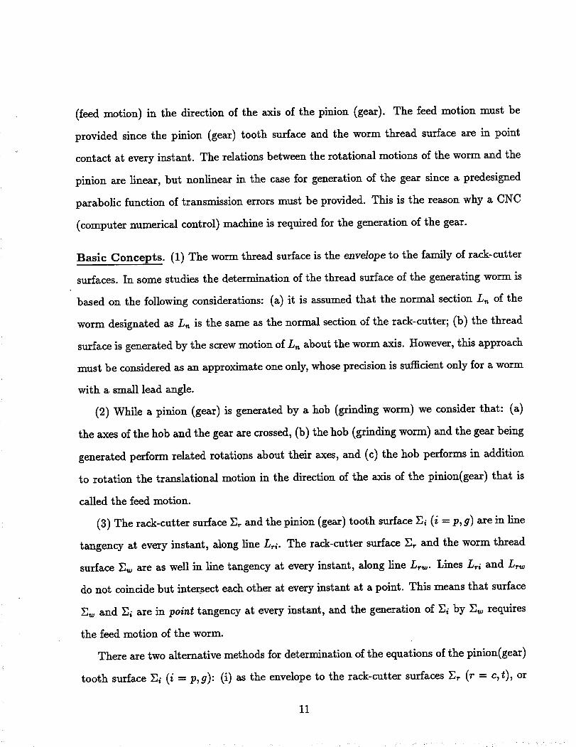
(feed motion) in the direction of the axis of the pinion (gear). The feed motion must be
provided since the pinion (gear) tooth surface and the worm thread surface are in point
contact at every instant. The relations between the rotational motions of the worm and the
pinion are linear, but nonlinear in the case for generation of the gear since a predesigned
parabolic function of transmission errors must be provided. This is the reason why a CNC
(computer numerical control) machine is required for the generation of the gear.
Basic Concepts. (1) The worm thread surface is the enve/ope to the family of rack-cutter
surfaces. In some studies the determination of the thread surface of the generating worm is
based on the following considerations: (a) it is assumed that the normal section L_ of the
worm designated as L,_ is the same as the normal section of the rack-cutter; (b) the thread
surface is generated by the screw motion of L,_ about the worm axis. However, this approach
must be considered as an approximate one only, whose precision is sufficient only for a worm
with a small lead angle.
(2) While a pinion (gear) is generated by a hob (grinding worm) we consider that: (a)
the axes of the hob and the gear are crossed, (b) the hob (grinding worm) and the gear being
generated perform related rotations about their axes, and (c) the hob performs in addition
to rotation the translational motion in the direction of the axis of the pinion(gear) that is
called the feed motion.
(3) The rack-cutter surface _ and the pinion (gear) tooth surface _i (i -- p,g) axe in line
tangency at every instant, along line L_i. The rack-cutter surface _ and the worm thread
surface _ are as well in line tangency at every instant, along line Lr_. Lines L_ and Lr_
do not coincide but intersect each other at every instant at a point. This means that surface
_w and _i axe in point tangency at every instant, and the generation of _i by _, requires
the feed motion of the worm.
There are two alternative methods for determination of the equations of the pinion(gear)
tooth surface _i (i -- P,9): (i) as the envelope to the rack-cutter surfaces _r (r -_ c,_), or
11

(ii) as the envelope to the two parameter family of surfaces of the worm. Both approaches
provide the same pinion (gear) tooth surface.
6. COMPUTERIZED SIMULATION OF MESHING AND CONTACT
The computerized simulation of meshing is based on the equations that provide contin-
uous tangency of pinion and gear tooth surfaces. The simulation can be accomplished for
aligned and misaligned gear drives. The computerized simulation of contact is based on
determination of the contact ellipse at each instant.
Three coordinate systems, Sp, S 9 and Sf are applied for investigation(fig. 7). The fixed
coordinate system Sf is rigidly connected to the housing of the gear drive (fig. 7(a)). The
movable coordinate systems Sp and Sg are rigidly connected to the pinion and the gear,
respectively. An auxiliary coordinate system Sq is applied for simulation of meshing when
the gear axis is crossed or intersected with the pinion axis instead of being parallel, and when
the shortest distance between the pinion and gear axes is changed. The misalignment angle
A_/is decomposed into two components, A% and ATy that represent the crossing angle and
the intersection angle, respectively. Fig. 7(b) and 7(c) show the orientation of coordinate
system Sq with respect to Sf when the axes of rotation of the gear and the pinion are crossed
or intersected, respectively. The pinion performs rotational motion about the zf-axis. The
axis of gear rotation is zq. The shortest distance between the axes of rotation is designated
as Epg.
We represent the pinion and gear tooth surfaces, Ep and Eg, and their unit normals
in coordinate system S f. Then we use the conditions of continuous tangency of the tooth
surfaces and simulate as well the gear misalignment.
The detern_nation of dimensions and orientation of the instantaneous contact ellipse
requires the knowledge of the principal curvatures and directions of the contacting surfaces
and the elastic approach of surfaces. This problem can be substantially simplified if the pinion
12

and gear principal curvatures and directions" are expressed in terms of the principal curvatures
and directions of the generating surfaces and parameters of motion [12,131 . The output of
TCA are [12,131: (i) the paths of contact on gear tooth surfaces, (ii) the transmission errors,
and (iii) the bearing contact formed by the instantaneous contact ellipses.
The simulation of meshing and contact has been performed for N.-W. gears and the
modified involute helical gears in the examples of section 8 to follow. The main results of
TCA are as follows:
(i) The linear finctions of transmission errors caused by misalignment are absorbed in-
deed by the predesigned parabolic function of transmission errors. The advantage of such
absorption is the reduction of noise and vibration.
(ii) The bearing contact for modified involute helical gears is stable, and the instantaneous
contact ellipse moves along but not across the tooth surface. We can expect that this will
benefit the conditions of lubrication.
(iii) The path of contact on the tooth surface is a helix in the case of an aligned gear
drive, and almost a helix for a misaligned gear drive.
(iv) Theoretically, the contact ratio for an unloaded gear drive is equal to one due to the
existence of transmission errors. However, the contact ratio under load is increased clue to
the deflection of teeth.
7. ANALYTICAL DETERMINATION OF TRANSMISSION ERRORS
CAUSED BY MISALIGNMENT
While computerized analysis of meshing enables one to determine the transmission errors
numerically. Our goals here are: (i) to provide analytical solutions, (ii) to prove that the
induced function of transmission errors is almost a linear one with respect to the rotation
angle _l of the pinion(driving gear), and (iii) represent this function in terms of the errors of
angular alignment and the gear design parameters. We apply for the solution the approach
13
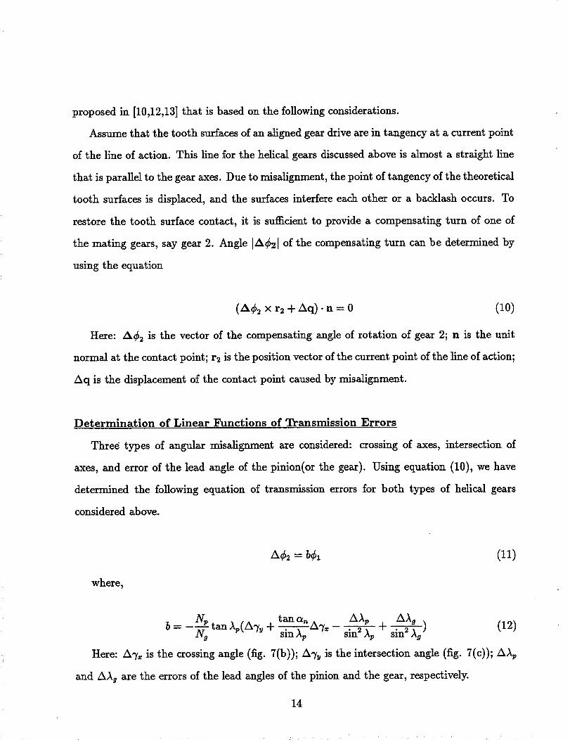
proposed in [10,12,13] that is based on the following considerations.
Assume that the tooth surfaces of an aligned gear drive are in tangency at a current point
of the line of action. This line for the helical gears discussed above is almost a straight line
that is parallel to the gear axes. Due to misalignment, the point of tangency of the theoretical
tooth surfaces is displaced, and the surfaces interfere each other or a backlash occurs. To
restore the tooth surface contact, it is sufficient to provide a compensating turn of one of
the mating gears, say gear 2. Angle IA¢21 of the compensating turn can be determined by
using the equation
(A$2 X r2 + Aq)-n = 0 (10)
Here: A$2 is the vector of the compensating angle of rotation of gear 2; n is the unit
normal at the contact point; r2 is the position vector of the current point of the line of action;
Aq is the displacement of the contact point caused by misalignment.
Determination of Linear Functions of Transmission Errors
Three types of angular misalignment are considered: crossing of axes, intersection of
axes, and error of the lead angle of the pinion(or the gear). Using equation (10), we have
determined the following equation of transmission errors for both types of helical gears
considered above.
where,
&¢2 = b¢1 (11)
Np tan a_ A AAp AA ab= -N-_qtartAr(A%_ + s--_n_-_p 7, sin 2 Ap + sin 2 Aa ) (12)
Here: A% is the crossing angle (fig. 7(b)); A% is the intersection angle (fig. 7(c)); AAp
and AAg are the errors of the lead angles of the pinion and the gear, respectively.
14

Influence of Change of Center Distance
The change of center distance of N.-W. gears and modified involute helical gears does
not cause transmission errors but only the shift of the bearing contact (the path of contact).
The shift can be evaluated as the change of the pressure angle determined as follows:
(i) In the case of N.-W. gears we have [10,18]
sinai, = AE -- Yot + Yoc (13)p_ - p_
where yor(r = c, t) is the coordinate of the circle center corresponding to circular arc
pr(r = c,t)(fig. 4); a,_ is the pressure angle in the normal section; a_ = as, where as is the
nominal value of the pressure angle, if AE, the change of the center distance, is equal to
zero. The difference (ce* - a_) indicates the shift of the path of contact (the bearing contact)
on the tooth surface.
(ii) The influence of the center distance change, in the case of modified involute helical
gears, is represented by the equation
2AE
sin a; = (sin 2 a, + --_ cos a,) °'s (14)
where a_ and a, represent the transverse pressure angles for the center distances (E+AE)
and E, respectively.
8. NUMERICAL EXAMPLES
The theory and approach developed in this paper are illustrated with two numerical ex-
amples: (i) the double circular arc gear drive and (ii) the modified involute helical gear drive.
The computations have been performed by application of TCA (Tooth Contact Analysis)
computer programs.
Example 1, Double Circular Arc Gear Drive
15

1 (module m,_The input design parameters used in this example are: P_ = 10 =-- =Sn.
2.54mm), N v = 12, N a = 94, ao = 27 °, fl0 = 30 °, L = 33mm, a = 0.00053, 6 = 0.001 mm.,
where _ is the elastic approach.
Aligned Gear Drive. Contact paths and contact ellipses on the surfaces for a single
tooth are shown in fig. 8 for the ideal case. Two contact points on the surface of a single tooth
exist only in the part of the area of meshing. Two contact points existing simultaneously are
shown by circles on the paths of contact (fig. 9). The transmission errors are determined by
a predesigned parabolic function with the maximal value of 8 arc seconds.
Influence of Misalignment. The misalignment has been simulated as the change A 7
of orientation of gear axes, when the axes become crossed or intersected instead of being
parallel, and by the change A)_ of the lead angle. There is only one instantaneous contact
point of gear tooth surfaces _v and _a: (i) contact point M (b) that is located on the lower
part of the tooth surface if the errors (A-y_, A% and A:k) are positive, and (ii) contact
point M (_) that is located on the upper surface if the errors above are negative. Surfaces _v
and _a at the second theoretical contact point are separated. However, the instantaneous
contact of surfaces at two points may be restored due to lapping or wearing of the surfaces
under the load.
The results of TCA for various errors of alignment are shown in Table 1. The results
show that the predesigned parabolic function indeed absorbs indeed the linear functions of
transmission errors caused by misalignment error A-y and the error of lead angle A_, and
keeps the same slope; the maximal transmission error is 8 arc seconds.
Influence of Change AE of Center Distance. The results of computation are: a_, =
22.0419 ° when AE = 0.03 ram; and 32.1911 ° when /kE = -0.03 ram. This means that
the bearing contact is shifted up and down depending on the sign of AE. The conditions
16

of meshing are the same as shown in fig. 9 since only AE, but not A-y and/k_, exist. Two
contact points exist only partially during the whole cycle of meshing.
Example 2_ Modified Involute Helical Gear Drive
1 (module m,_ 5.8ram),The input design parameters used in this example are: P,_ = 5 :-- =Sn.
Np = 20, N 9 = 100, _ = 20 °, _0 = 30 °, L = 1.6 in. (40.64mm), a = 0.0015, _ =
0.0003 in(O.O07 ram).
Aligned Gear Drive. Figures 10 and 11 show the predesigned parabolic type of trans-
mission errors and the contact pattern for the case without misalignment (A% = A% =
A)_ v = 0, AE = 0). The maximal transmission error is 8 arc seconds.
Influence of Misalignment. The results of investigation of the influence of misalign-
ment (Table 2) show: (a) the predesigned parabolic function of transmission errors indeed
absorbs the linear function of transmission errors caused by misaligument, and (b) the con-
tact paths on the pinion- gear tooth surfaces are located in the neighborhood of the ideal
contact paths.
Influence of Change AE of Center Distance. The transverse pressure angle is slightly
changed due to the change of the center distance: a; = 22.84 ° when AE = 0.1 ram.; and
a; = 22.76 ° when AE = --0.1 ram. (oq = 22.80 ° when AE = 0 ).
9. CONCLUSION
Based on the results contained in this study, the following conclusions can be made:
(1) The absorption of a linear function of transmission errors by a predesigued parabolic
function has been confirmed.
(2) An approach for localization of the bearing contact for helical gears has been developed.
17

(3) Conjugation of gear tooth surfaces by application of two imaginary rack-cutters has
been developed.
(4) Pinion and gear tooth surfaces with modified topology generated by a worm for deter°
mination of a favorable shape of transmission errors has been developed.
(5) Computerized simulation of meshing and contact has been investigated.
(6) Analytical determination of functions of transmission errors caused by misalignment
has been developed.
(7) Two numerical examples of N.-W. gear drive and modified involute helical gear drive
for illustration of the developed theory have been provided.
ACKNOWLEDGMENT
The authors express their deep gratitude to the NASA Lewis Research Center and the
Gleason Memorial Fund for the financial support of the research.
REFERENCES
1 Novikov, M.L., USSR Patent No. 109, 750, 1956.
2 Wildhaber, E., US Patent No.l, 601,750 issued Oct. 5, 1926, and Gears with Circular
Tooth Profile Similar to the Novikov System, VDI Berichte, No. 47, 1961.
3 Kudrjavtsev, V.N., Epicycloidal Trains, Mashgis, 1966.
4 Winter, H., and Loom_an, J., Tools for Making Helical Circular Arc Spur Gears, VDI
Berichte, No. 47, 1961.
18

5 Litvin, F.L., The Investigation of the Geometric Properties of a Variety of Novikov
Gearing, The Proceedings of Leningrad Mechanical Institute, 1962, No. 24 (in Rus-
sian).
6 Davidov, J.S., The Generation of Conjugate Surfaces by Two Rigidly Connected Tool
Surfaces, Vestnik Mashinostroyenia, 1963, No. 2.
7 Litvin, F.L. and Tsay, C.-B., Helical Gears With Circular Arc Teeth, J. Mech Transm
Auto Des, 107(1985), 556-564.
8 Kudrjavtsev, V.N., Machine Elements, Mashgis, 1980.
9 Chinese Standard, J B 2940-81, 1981.
10 Litvin, F.L. and Lu, J., Computerized Simulation of Generation, Meshing and Contact
of Double Circular-Arc Helical Geaxs, Math. Comput. Modelling, 18(1993), 31-47.
11 Litvin, F.L., Zhang, J., Handschuh, R.F. and Coy, J.J., Topology of Modified Helical
Gears, Surf. Topography, 2(1989), 41-58.
12 Litvin, F.L., Theory of Gearing, NASA Reference Publication 1212, 1989.
13 Litvin, F.L., Gear Geometry and Applied Theory, Englewood Cliffs, NJ, Prentice Hall,
1994.
14 Reishaner CNC Gear Grinding Machines, Catalogs, Switzerland
15 Litvin, F.L., Krylov, N.N. and Erikhov, M.L., Generation of Tooth Surfaces by Twopara-
metric Enveloping, J. Mechanism and Machine Theory, 10 (1975b), 365-373.
16 Litvin, F.L. Theory of Gearing, (in Russian), 1st ed. in 1960, 2nd ed. in 1968.
19

Table 1: The results of TCA for misaligned N.-W. gear drive
n_salignment
without parabolic function
a-----O
jump
with parabolic function
a -- 0.00053
A _2maz position errors
A% 3' --0.00011 12.3" 8" --96"
--31 0.00011 12.3" 8" 105.5"
A"T= 31 --0.00019 21" 8" 13"
-31 0.00019 21.0" 8" 2.6"
AAp 31 0.00026 27.8" 8" 2.6'1
--3' --0.00026 17.8" 8" 13.0"
' -- arc minute, ,, m arc second
Table 2: The results of TCA for involute helical misaligned gear drive
without parabolic function with parabolic function
misalignment a = 0 a = 0.0015
b jump A¢2,_a= position errors shift of contact paths
A% 4' --0.0004 25.9" 8 # --1.2" up
--4' 0.0004 25.9" 8# 3.2" down
A% 41 --0.00017 11.0" 8" --137.8" up
--4' 0.00017 11.0" 8" 138.1" down
AAo 4' 0.00054 35.0" 8" 3.2" down
-4' -0.00054 35.0" 8" 1.0" up
' m arc minute, " -- arc second
2O

_2
27F
NI
arctan(b)
_- - cp1i
(b)
Figure 1: Transmission function and transmission errors for a misMigned
gear drive21

(a)_2
Ideal transmission function
(b)
Fig. 2 Transmission function and predesigned parabolic function oftransmission errors
22

/V
!
(b) Rack-cutter c
N
,/
(c) Rack-cutter t
Figure 3: Surfaces of imaginary rack-cutters
23

e{z
(a) Chinese standard
!
I i
P_-" 7Tm i
//_ o_Cxo_,
l \__ //
(b) USSR standard
Figure 4: Standardized rack-cutter profiles
24
Parallel to gear axisZt / Za
0.25Xa
(b)
(c)
?ack Cutter Sc
m
Figure 5: Schematic of rack-cutters for generation of helical involute
gears
25

Y_
X¢
O_
_ rt Y_
St
Xg
0_09
(b)
D Xt
--Xn
Figure 6: Generation of pinion and gear by rack-cutters
26

Xg
H/ _zq _
yq / --
_ olPp
(a)
ZI Z_
/
_g
Xl
AT_ zq
Oq,O. _
Yq
(b)
Xq
(o)
Fig. 7 Coordinate systems applied for simulation
of meshing
27

oatact _)at_s | -C 0 SSS_ee
el o
Z_ M(b)
Contact paths
/M(b_
(b)
Fig. 8 Paths of contact and contact ellipses on
pinion-gear tooth surfaces
28

o
MbGeor tooth
(a)
}Pmr 1
A&&&&&&&&OOO00
I OCCCC&&&&&&&&&
M° _b
}Pair 2
I
t 'I I i I _ ¢I
_42 ° -24 ° -12 ° 12 ° 24 ° 42 °
(b)
Figure 9: Sequence of contact points for aligned gear drive
29

"0C000
b_n_
C_rw-
C3
ct_Lr_
-I0 /
-20
cr_
n'-rw_ -_ -.
-3O-3o -2o -_o o io 20 5o _o so so
PINION ROTBTiON RNGLC !degree}
70 BO
Figure 10: Transmission errors for modified involute helical gears with
aligned axes
3O

w
Z
2::
gERR
I I////I/Y//I/////I
IIiiliiiiiiiii/II
PINION
-3o -20 -io 0 m 20 soRXIS Z _M
Figure 11: Contact pattern for modified involute helical gears with aligned
axes
31

Form ApprovedREPORT DOCUMENTATION PAGE OMBNo. 0704-0188
Publicreportingburdenforthiscollectionof informationis estimatedto average1 hourper response,includingthe timeforreviewinginstructions,searchingexistingdatasources,gatheringandmaintainingthedataneeded,andcompletingandreviewingthecollectionof information.Sendcommentsregardingthisburdenestimateor anyotheraspectofthiscollectionof information,includingsuggestionsforreducingthisburden,toWashingtonHeadquartersServices,Directoratefor InforrnationOperationsandReports,1215JeffersonDavisHighway,Suite1204,Arlington,VA 22202-4302,andtotheOfficeof ManagementandBudget,PaperworkReductionProject(0704-0188),Washington,DC 20503.
1. AGENCY USE ONLY (Leave blank) 2. REPORT DATE 3. REPORT TYPE AND DATES COVERED
August 1994 Technical Memorandum5. FUNDING NUMBERS4. TITLE AND SUBTITLE
Computerized Design and Generation of Low-Noise Helical Gears WithModified Surface Topology
6. AUTHOR(S)
F.L. Litvin, N.X. Chen, J. Lu, and R.F. Handschuh
7. PERFORMING ORGANIZATION NAME(S) AND ADDRESS(ES)NASA Lewis Research Center
Cleveland, Ohio 44135-3191and
Vehicle Propulsion Directorate
U.S. Army Research LaboratoryCleveland, Ohio 44135-3191
9. SPONSORING/MONITORING AGENCY NAME(S) AND ADDRESS(ES)
National Aeronautics and Space Administration
Washington, D.C. 20546-0001and
U.S. Army Research Laboratory
Adelphi, Maryland 20783-1145
WU-505-62-361L162211A47A
8. PERFORMING ORGANIZATIONREPORT NUMBER
E-9056
10, SPONSORING/MONITORINGAGENCY REPORT NUMBER
NASA TM-106696ARL-TR-573
11. SUPPLEMENTARY NOTESPrepared for the 23rd Mechanisms Conference sponsored by the American Society of Mechanical Engineers, Minneapolis, Minnesota, September 11-14
1994. F.L. Litvin, N.X. Chen and J. Lu, University of Illinois at Chicago, Department of Mechanical Engineering, Chicago, Illinois; R.F. Handschuh,
Vehicle Propulsion Directorate, U.S. Army Research Laboratory, NASA Lewis Research Center. Re., ponsible person, R.F. Handschuh, organization
code 2730r (216_ 433-3969.12a. DISTRIBUTION/AVAILABILITY STATEMENT 12b. DISTRIBUTION CODE
Unclassified -Unlimited
Subject Category 37
13. ABSTRACT (Maximum 200 words)
An approach for design and generation of low-noise helical gears with localized bearing contact is proposed. The ap-proach is applied to double circular arc helical gears and modified involute helical gears. The reduction of noise andvibration is achieved by application of a predesigned parabolic function of transmission errors that is able to absorb adiscontinuous linear function of transmission errors caused by misalignment. The localization of the bearing contact is
achieved by the mismatch of pinion-gear tooth surfaces. Computerized simulation of meshing and contact of the designedgears demonstrated that the proposed approach will produce a pair of gears that has a parabolic transmission error functioneven when misalignment is present. Numerical examples for illustration of the developed approach are given.
14. SUBJECT TERMS
Gears; Transmissions
17. SECURITY CLASSIFICATIONOF REPORT
Unclassified
NSN 7540-01-280-5500
18. SECURITY CLASSIFICATIONOF THIS PAGE
Unclassified
19. SECURITYCLASSIRCATIONOF ABSTRACT
Unclassified
15. NUMBER OF PAGES33
16. PRICE CODE
A0320. LIMITATION OF ABSTRACT
Standard Form 298 (Rev. 2-89)PrescribedbyANSI Std.Z39-18298-102