Embed Size (px)
Citation preview

i
, ..... 4///..f/7T_- 2_zz7/N/N///N///NI//I/////I
3 1176 00154 3744
NASA Technical Memorandum 80227
NASA-TM-80227 19800009768
PERFORMANCE ESTIMATESOF A BOEING747-I00TRANSPORT MATED WITH ANOUTSIZECARGOPOD _,_:_--..,.,_____:___
i"O!_ I_[EFE_,NCE
LloydS. Jernell _ >-J
February 1980 ,.._;,,_c_,;.,,,! 2 i;i;0
tU/ A
https://ntrs.nasa.gov/search.jsp?R=19800009768 2020-03-21T19:58:19+00:00Zbrought to you by COREView metadata, citation and similar papers at core.ac.uk
provided by NASA Technical Reports Server


PERFORMANCEESTIMATESOF A BOEING747-100TRANSPORTMATEDWITH AN OUTSIZECARGOPOD
Lloyd S. JernellNASALangley Research Center
SUMMARY
A study has been conducted to determine the design-mission performanceof a Boeing 747-100 aircraft mated with an outsize cargo pod. The basic designrequirement was the rapid deployment of a combat-loaded mobile bridge launcherfrom a United States east-coast staging base to Europe. Weight was minimizedby stripping the aircraft of unneeded, quick-removal items and by utilizinggraphite-epoxy composite materials for most pod components. The missionanalysis, based on wind tunnel data and full-scale carrier aircraft and enginedata, indicates that for the specified maximumtakeoff gross weight of 3,269.44kN (735,000 Ibf) and payload weight of 542.68 kN (122,000 Ibf), the maximumranqe is approximately 7,185 km (3,880 n.mi.). The corresponding air time isabout 10.5 hours.
INTRODUCTION
Presently there exists a critical need for increased airlift capability inthe long range deployment of outsize cargo during limited-warfare conflicts.Proposals have been made to alleviate this shortfall by providing a stand-bycommercial fleet of large wide-body transports modified to carry outsize eouip-ment. However, the overall systems cost of aircraft incorporating such extensivemodifications would likely be prohibitively high due primarily to the performancepenalties incurred during civil operations.
In order to minimize aircraft modification and the resultant adverse effectson the efficiency of commercial operations, a preliminary study was conducted todetermine the feasibility of mating a cargo pod to the underside of a large wide-body aircraft. The primary design-mission requirement was the rapid deploymentof outside cargo from a United States east-coast staging base to Europe. A mobilebridge launcher, consisting of launch mechanism and bridge mounted on an M60 tankchassis, was selected as the design payload because it is among the bulkier andheavier items in the military-airlift inventory. Additional design-missionspecifications, descriptions of the configurations considered, and the studyresults are reported in reference I. Reference 2 presents the results of a sub-sequent study in which a slightly larger pod was considered for transporting, inaddition to outsize military cargo, modular elements of the NASASpacelab.
Since the pod concept appeared to be feasible, tests were conducted in theLangley V/STOL wind tunnel using a O.03-scale model of the carrier aircraftwith the retractable-gear pod of reference I. The results are documented inreference 3.
#N - /?o J2

The purposeof this paper is to presentthe resultsof a detailedanalysisof the designmission specifiedin referenceI, utilizinga Boeing 747-100carrieraircraftpoweredby Pratt and WhitneyJT9D-7Aengines,and a structurallymodified versionof the retractable-gearpod of reference1. The data are basedon the resultsof an analysisof the aircraftand pod weights, the wind tunneldata of reference3, the full-scalecarrieraircraftperformancedata of reference4, and the engine performanceestimatesof reference5.
SYMBOLS
Values are presentedin both SI and U.S. customaryUnits. Measurementsand calculationswere made in U.S. CustomaryUnits.
CD drag coefficient, DragqS
CD,p parasitedrag coefficient,ParasitedragqS
CD,p,min minimum parasitedrag coefficient
CD, trim trimmeddrag coefficient,TrimmeddragqS
CL lift coefficient,LiftqS
CAS calibratedairspeed
Fn net thrust
GW gross weight
g gravitationalconstant
h altitude
M Mach number
q dynamicpressure
R Reynoldsnumber
S wing referencearea
TSFC thrust specificfuel consumption
V velocity

w fuel flow rate
DESIGNMISSION
The primary design-mission requirement is that of reference I; namely, therapid deployment of a mobile bridge launcher from a United States east-coaststaging base to Europe. The payload weight, which includes the combat-loadedvehicle and the necessary shoring equipment, is 542.68 kN (122,000 Ibf). Itwas also specified that the pod be unpressurized in order to simplify construc-tion and to minimize cost and weight. Hence, according to military specifica-tions for unpressurized cargo, maximumaltitude is limited to 5.486 km (18,000 ft).
CONFIGURATION
A three-view drawing of the configuration with full-scale dimensions ispresented in figure I. An isolmetric view showing additional details of thepod is provided in figure 2.
Carrier Aircraft
Because of the mission payload and range requirements, the only currentcommercial transports suitable for adaptation to the cargo-pod concept areBoeing 747 aircraft at the -I00 and -200 series. According to reference 6, asof year-end 1978 U.S. airlines had in operation 94 transports of the -I00 seriesand 13 of the -200 series. Since aircraft of the former series have less fuelcapacity and lower maximumtakeoff gross weights, a conservative approach wastaken by selecting for the carrier aircraft role a typically configured 747-100powered by Pratt and Whitney JT9D-7A engines. In the early stages of preliminarydesign it became apparent that the operating empty weight of the combined air-craft and pod could be critical for the specified design mission. Thus consid-erable attention was devoted to weight reduction, including stripping the carrieraircraft of items which are not essential to the military mission and which canbe removed in a relatively short time. These items include the landing gear,seats, galleys, and passenger-emergency equipment.
Pod
In the study of reference I, which considered an all-metal pod structureand the bridge launcher as design payload, the weight of the retractable-gearpod was estimated to be 212.18 kN (47,700 Ibf). However, subsequent studiesusing the structural-design criteria and improved computer methods of reference2 indicated that the all-metal pod weight can be reduced to 195.81 kN (44,020Ibf). A cursory follow-on study was conducted to determine the potential forthe further reduction in pod weight by the utilization of composite materials.Based on the allowable-stress data and analysis methods of reference 7, graphite-apoxy material was selected. The results indicated that this material could beused for essentially all components of the pod body and much of the landing gear,with an attendant 15- to 20-percent reduction in pod total weight.
3

The present study assumes maximum utilization of composite materials for podconstruction and a resulting weight reduction of 15 percent from the refinedall-metal estimate. Hence, the weight of the pod employed herein is estimatedto be 166.45 kN (37,420 Ibf). A summary of the weights for this configurationis presented in Table I.
MISSION ANALYSIS
The trimmed lift-drag polars, as determined from the wind tunnel data of
reference 3 and the estimated variations in parasite drag coefficient CDwith lift coefficient, are presented in figures 3(a) and 3(b) for the pu_Z_ffand pod-on configurations, respectively. The center of gravity is located atthe quarter-chord point of the wing mean aerodynamic chord. The Reynolds numberis 1.08 x 10⁶ .
Variations of minimum parasite drag coefficient CD D.mn" with Reynoldsnumber are shown in figure 4. For both configurations,'_eldrag estimates ofreference I were greater than were determined from the wind tunnel data ofreference 3. Rather than using the model data with the greater extrapolation toflight Reynolds numbers, the present pod-off CD n min for the cruise Reynoldsnumber range was obtained by utilizing the full-_le aircraft and engine per-formance data of references 4 and 5. It will be noted that these values are
somewhat higher than those of reference I The pod-on CD p,min used in themission analysis was assumed to be equal to the pod-off va_ue plus the increasedue to the pod as estimated by reference i.
The design-mission weights, time, and range, which were calculated for atakeoff gross weight of 3,269.44 kN (735,000 Ibf) using Military Airlift Commandlong-range fuel reserves, are presented in Table II. Pod-on aerodynamic charac-teristics were not available for the takeoff and first-segment climb configura-
_tions. Therefore, it was assumed that for these segments, the pod-on and pod-off fuel burn, distance, and air time were in proportion to those calculated forthe second-segment climb. Since fuel burn for the second segment is partly afunction of gross weight, and thus affected by the amount of fuel consumedduring takeoff and the first-segment climb, iterative calculations wererequired.
The second-segment climb schedule, shown in figure 5 in terms of Mach numbervariation with altitude, consists of a climb at 463 km/hr (250 kts) calibratedairspeed CAS from an altitude of 0.46 km (1,500 ft) to 3.05 km (I0,000 ft).This climb is followed by an acceleration, and then a continued climb at593 km/hr (320 kts) CAS to 5.49 km (18,000 ft).
Uninstalled thrust values for the JT9D-7A engine at maximum climb rating,ICAO standard atmosphere, were obtained from reference 5. The values were thenassessed a 3-percent penalty for installation, air bleed, and power extractionto determine the estimated installed climb thrust. The rate of climb dh wasobtained from dt
dt 1 + V d__VV4 g dt

The resultingvalues,as affectedby altitudeand gross weight, are providedin figure 6. The variationof fuel flow rate with altitudefor the second-segmentclimb, as determinedfrom reference5, is shown in figure 7.
The effectsof thrust and Mach number on thrust specificfuel consumption,TSFC, at the design cruise altitudeare shown in figure8. As before,a 3-percent penaltywas appliedto the data of reference5 to obtain the installedengine performance. Cruise performancecalculations,in which Mach number wasoptimizedfor maximum range,were determinedin fuel-burnincrementsof appro-ximately88.96 kN (20,000Ibf). The effect of gross weight on cruiseMachnumber is shown in figure9. Using the gross weightsof Table II, it will benoted that the optimumMach number varies approximatelylinearlyfrom an initialvalue of 0.675 to an end-of-cruisevalue of 0.550. Descent,approach,andlandingperformancewere estimatedusing the data of reference4, with adjust-ments to account for pod effectsas determinedfrom figures3 and 4.
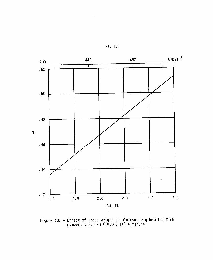
The design-missionfuel reserves (see Table II) were computedto meet thelong-rangemissionrequirementsspecifiedby the MilitaryAirliftCommand.Figure 10 shows the effect of gross weight on minimum-dragholdingMach numberat cruise altitude. These data, togetherwith the specificfuel consumptionvalues to figure 8, were used to calculatethe fuel requiredto hold at maximumendurance.
The mission analysisindicatesthat for the assumedmaximum takeoffgrossweight of 3,269.44kN (735,000Ibf) the design-missionmaximum range is appro-ximately 7,185 km (3,880n.mi.). The correspondingair time is about 10.5 hours.
CONCLUDINGREMARKS
A study has been conductedto determinethe design-missionperformanceof aBoeing 747-100aircraftmated with an outsizecargo pod. The basic designrequirementwas the rapid deploymentof a combat-loadedmobile bridge launcherfrom a United States east-coaststagingbase to Europe. Weightwas minimizedbystrippingthe aircraftof unneeded,quick-removalitems and by utilizinggraphite-epoxy compositematerialsfor most pod components. The mission analysis,basedon wind tunnel data and full-scalecarrieraircraftand engine data, indicatesthat for the specifiedmaximum takeoffgross weight of 3,269.44kN (735,000Ibf)and payloadweight of 542.68 kN (122,000Ibf), the maximum range is approximately7,185 km (3,880n.mi.). The correspondingair time is about 10.5 hours.
5

REFERENCES
1. Quartero, C. B.; Washburn, G. F.; and Price, J. E.: Boeing 747 AircraftWith External Cargo Pod. NASACR-158932, 1978.
2. Price, J. E.; Quartero, C. B.; Smith, P. M.; and Washburn, G. F.: Boeing747 Aircraft With Large External Pod for Transporting Outsize Carqo.NASACR-159067, 1979.
3. Jernell, Lloyd S.; and Croom, Delwin R.: Effects of a Military Cargo Podand Tail Fins on the Aerodynamic Characteristics of a Large Wide-bodyTransport Model. NASATM 80052, 1979.
4. The Boeing Company: Performance of the Boeing Transport Models 747SR,747-200B, -200C, -20OF, and 747-100 with JT9D-7 Engines and JT9D-7A Engines.D6-33382, 1972.
5. Pratt and Whitney Aircraft Division, United Technologies Corporation:JT9D Commercial Turbofan Engine Installation Handbook. Marketing Support.1967. (Revised August 1975.)
6. The Boeing Company: Jet Airplane Fleets of the World, Year-End 1978. Y8453.June 1979.
7. Third Conference on Fibrous Composites in Flight VehicleDesign - Part I.NASATM X-3377, 1976.
6

TABLE I.- WEIGHTSSUMMARY;BOEING747-100 WITH JT9D-7A ENGINES
(a) Maximumdesign- and performance-limited weights
kN Ibf
Taxi 3,282.79 738,000Takeoff gross (maximum certified) 3,269.44 735,000Zero fuel 2,341.99 526,500Fuel 1,406.97 316,300Landing 2,508.80 564,000
(b) Aircraft/pod design-mission weight breakdown
kN Ibf
Structure 808.24 181,700Landing gear 0 0Propulsion 202.79 45,500Systems 111.65 25,100Furnishings 62.28 14,000Paint 3.11 700
Manufacturer's empty weight 1,.188.08 267,090Standard and operational items 9.03 2,030Operating empty weight, aircraft only 1,197.11 269,120Pod 166.45 37,420Operating empty weight, aircraft with pod 1,363.56 306,540Payload 542.68 122,000Zero fuel weight 1,906.24 428,540Fuel at brake release 1,363.20 306,460Takeoff gross weight 3 269.44 735 000
7

CO
TABLE II.- MISSION PERFORMANCE;BOEING 747-100 WITH POD, JT9D-7A ENGINES
Mission segment Gross weight Fuel remaining _ Air time _" RangekN (Ibf) kN (Ibf) hr km (n. mi.)
- 3,269.44 (735,000) 1,363.20 (306,460) 0 0 (0)Takeoff m
- 3,264.24 (733,830) 1,358.00 (305,290) .02 0 (0)Firstsegment climb
- 3,254.36-(731,610) 1,348.12 (303,070) .06 17 (9)Second segment climb--
- 3,203.43 (720,160) 1,297.19 (291,620) .30 169 (91)Cruise
- 2,090.09 (469,870) 183.85 (41,330) 10.25 7,106 (3,837)Descent
- 2,085.59 (468,860) 179.35 (40,320) 10.39 7,189 (3,882)Approach and land
- 2,078.39 (467,240) 172.15 (38,700) 10.47 7,189 (3,882)
Reserves (Military Airlift Command):
I0 percent trip air time (not to exceed i hr.), kN (Ibf) ................................. 85.85 (19,300)Hold at 5.486 km (18,000 ft) for I hr, 10 min; kN (Ibf) ................................. 86.30 (19,400)
Total reserves, kN (Ibf) .......................................................... 172.15 (38,700)

Figure 1. - Configurat ion geometry. Full-scale dimensions a re in meters, wi th feet in parentheses.

%
Nose-geardooro
!#
; Main-gearfairing
Clamshellloadingdoor
/ Hingeline
Main-geardoors
Figure2. - Configurationisometric view.

. (a ) Pod o f f .
F igure 3. - Wind tunnel trimmed l i f t - d r a g p o l a r and est imated p a r a s i t e drag c o e f f i c i e n t ; c.g. a t 0.25 C; R = 1.08 x 10⁶.

(b) Pod on.
Figure 3 . - Concluded.

2o I--0 Wind tunnel
PresentanalysisMethod of !ferencel
.I0
.08
.06
CD,p,min
.04 m
.02 m
.011 2 40 60 80 100x106
R
(a) Pod off.
Figure 4. - Effect of Reynolds number on minimum parasitedrag coefficient.

.2o i0 Wind tunnel
Present anal_sisMethod of reierence 1
.I0
.O8
.O6
CD,p,min
.O4
.01I 2 40 60 80 lOOxlO6
R
(b) Pod on.
Figure 4. - Concluded.

F i g u r e 5. - V a r i a t i o n o f Mach number w i t h a l t i t u d e d u r i n g ' second-segment cl imb.

dh ftd-T , --_mln
8 12 16 20xlO2
7
20x1036 MN (Ibf)
j-- 3.16 (710,000)\._XX /
5 _ 3.25 (730,000) 16
3.29 (740,000)
4 \12
, __3 \_'
8
\
\,,\
0 0
200 300 400 500 600 700
dh m_- , min
Figure 6. - Rate of climb for engine maximum-climbrating.

1.3 1.4 1.5 1.6 1.7 1.8
Jsa- W Y sec
F igure 7. - V a r i a t i o n o f f u e l f l o w r a t e per engine w i t h a l t i t u d e f o r engine maximum-climb r a t i n g .

Fn, Ibf
7 8 9 I0 Ii 12 13 14xlO3I I I I I I I I
68 -,
660
",...66 "
64 _
_,_ _ _._ .7 620
62 '_
6o _-_580
L 58 _' _ L
d _ dm 56
....._-_. 540
54 .5
--....52 "_
"_ 500
50 "_'-
48
460
4630 34 38 42 46 50 54 58 62
Fn, kN
Figure 8. - Thrust specific fuel consumption; 5.486 km (18,000 ft)altitude.

GW, Ibf
440 480 520 560 600 640 680 720 760x103
i I I I i i I I I.70
/.-/
.66 J
.62 J
,58 J
d
,54 J
.5O1.8 2.0 2.2 2.4 2.6 2.8 3.0 3.2 3.4
GW,MN
Figure 9. - Effect of gross weight on maximum-range cruise Mach number; 5.486 km (18,000 ft ) altitude.
GW, I bf
400 440 480 520_I03r i I I
.52
.5o ;f
.48 /
J7
.46 j
.44 _ "
.421.8 1.9 2.0 2.1 2.2 2.3
GW,MN
Figure 10. - Effect of gross weight on minimum-drag holding Machnumber; 5.486 km (18,000 ft) altitude.


1. Report No. 2. Government Accession No. 3. Recipient's Catalog No.
NASATH-802274. Title and Subtitle 5. Report Date
Performance Estimates of a Boeing 747-100 Transport Febrbary 1980Mated With an Outsize Cargo Pod 6. PerformingOr_nizationCode
7. Author(s) 8. PerformingOrgamzation Report No.
Lloyd S. Jernell10. Work Unit No.
9. Performing Organization Name and Address 530-04-13-01
Lu-jlan_le_Research Center 11 Contractor GrantNo.NASAHampton, Virginia 23665
13, Type of Report and Period Covered
12. Sponsoring Agency Name and Address
National Aeronautics and Space Administration Technical MemorandumWashington, De 20546 14.Army Project No.
115. Supplementary Notes
16. Abstract
A study has been conducted to determine the design-mission performance of aBoeing 747-100 aircraft mated with an outsize cargo pod. The basic designrequirement was the rapid deployment of a combat-loaded mobile bridge launcherfrom a United States east-coast staging base to Europe. Weight was minimizedby stripping the aircraft of unneeded, quick-removal items and by utilizinggraphite-epoxy composite materials for most pod components. The missionanalysis, based on wind tunnel data and full-scale carrier aircraft and enginedata, indicates that for the specified maximumtakeoff gross weight of 3,269.44kN (735,000 lbf) and payload weight of 542.68 kN (122,000 lbf), the maximumrange is approximately 7,185 km (3,880 n.mi.). The corresponding air time isabout 10.5 hours.
17. Key Words (Suggested by Author(s)) 18. Distribution Statement
Large military cargo pod UNCLASSIFIED- UNLIMITEDAircraft/cargo pod integration
STARCATEGORY05
19. Security Cla_if. (of this report} 20. Security Classif. (of this page) 21. No. of Pages 22. Price"
UNCLASSI FI ED UNCLASSI FIED 20 $4. O0
"For sale by the National Technical Information Service, Springfield, Virginia 22161NASA-Langl ey, 1980


![arXiv:1911.01040v2 [stat.ME] 18 Dec 2019p n B n( bL 0) + W n (7) where B n p n I p 1 n X i M ix ix T i ; and W n 1 p n X i M ix i" i: Predictability of (M i) i n ensures that W n is](https://img.pdfslide.us/doc/110x75/60f6b745f4ae2e32183880cd/arxiv191101040v2-statme-18-dec-2019-p-n-b-n-bl-0-w-n-7-where-b-n-p-n.jpg)