Embed Size (px)
Citation preview
I MSS SP-85-2002 zyxwvutsrqponmlkjihgfedcbaZYXWVUTSRQPONMLKJIHGFEDCBA
Gray Iron Globe & Angle Valves
Flanged and Threaded Ends
Standard Practice
Developed and Approved by b e
Manufacturers Standardization Society of the
Valve and Fittings Industry, Inc.
127 Park Street, NE
Vienna, Virginia 221 80
(703) 281 -661 3
COPYRIGHT 2003; Manufacturers Standardization Society of the Valve and Fittings
Document provided by IHS Licensee=Fluor Corporation/2110503105, User=, 05/22/2003 19:40:35 MDT Questions or comments about this message: please callthe Document Policy Management Group at 1-800-451-1584.
--```,`,,````,,,```,,,,`,`,,`,-`-`,,`,,`,`,,`---www.b
zfx
w.c
om
falatghareh.irfalatghareh.ir
MSS zyxwvutsrqponmlkjihgfedcbaZYXWVUTSRQPONMLKJIHGFEDCBASTANDARD PRACTICE SP-85
This MSS Standard Practice was developed under the consensus of the MSS Technical Committee 106 and the
MSS Coordinating Committee. The content of this Standard Practice is the result ofthe efforts of competent and
concerned volunteers to provide an effective, clear, and non-exclusive specification that will benefit the industry
as a whole. This MSS Standard Practice is intended as a basis for common practice by the manufacturer, the
user, and the general public. The existence of an MSS Standard Practice does not in itself preclude the manufac-
ture, sale, or use of products not conforming to the Standard Practice. Mandatory conformance is established
only by reference in a code, specification, sales contract, or public law, as applicable.
Unless otherwise specifically noted in this MSS SP, any standard referred to herein is identified by
the date of issue that was applicable to the referenced standard(s) at the date of issue of this MSS
SP. (See Annex C)
In this Standard Practice all notes, annexes, and figures are constnied to be essential to the understand-
ing of the message of the standard, and are considered part of the text unless noted zyxwvutsrqponmlkjihgfedcbaZYXWVUTSRQPONMLKJIHGFEDCBAas ‘supplemental.’
All footnotes appearing in this document are construed as ‘supplemental’ where their information does not modiQ the text to which they refer.
U.S. customary zyxwvutsrqponmlkjihgfedcbaZYXWVUTSRQPONMLKJIHGFEDCBAunits in this SP are the standard; the metric units are for reference oniy.
Non-toleranced dimensions in this Standard Practice are nominal and, unless otherwise specified, shall be
considered “for reference only”. zyxwvutsrqponmlkjihgfedcbaZYXWVUTSRQPONMLKJIHGFEDCBAI
Substantive changes in this 2002 edition are “flagged” by
parallel bars as shown on the margins of this paragraph.
The specific detail of the change may be determined by
comparing the material flagged with that in the previous I edition. zyxwvutsrqponmlkjihgfedcbaZYXWVUTSRQPONMLKJIHGFEDCBAAny part zyxwvutsrqponmlkjihgfedcbaZYXWVUTSRQPONMLKJIHGFEDCBAof this standard zyxwvutsrqponmlkjihgfedcbaZYXWVUTSRQPONMLKJIHGFEDCBAmay be quoted Credit lines shouldread ‘Extractedfiom Ii/trSSP-SS, 2002, with permission
of the publisher, the Manufacturers Standardization Society. ’ Reproduction prohibited under conright convention
unless written permission is granted by the Manufacturers Standarduation Society of the Valve and Fittings Industry,
Inc.
Originally Approved April 1976
Copyright Q zyxwvutsrqponmlkjihgfedcbaZYXWVUTSRQPONMLKJIHGFEDCBA1984 by
Manufacturers Standardization Society of the
Valve and Fittings Industry, Inc.
Printed in U.S.A.
1
COPYRIGHT 2003; Manufacturers Standardization Society of the Valve and Fittings
Document provided by IHS Licensee=Fluor Corporation/2110503105, User=, 05/22/2003 19:40:35 MDT Questions or comments about this message: please callthe Document Policy Management Group at 1-800-451-1584.
--```,`,,````,,,```,,,,`,`,,`,-`-`,,`,,`,`,,`---www.b
zfx
w.c
om
falatghareh.irfalatghareh.ir
MSS STANDARD zyxwvutsrqponmlkjihgfedcbaZYXWVUTSRQPONMLKJIHGFEDCBAPRACTICE SP-85
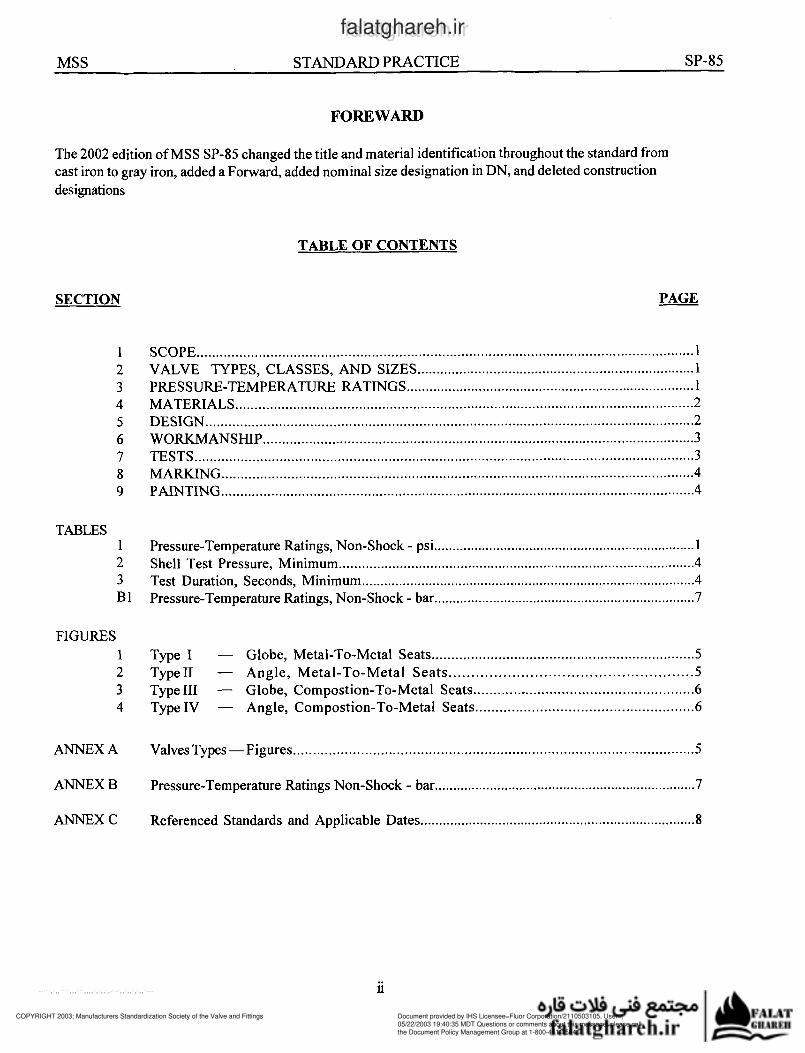
FOREWARD
The 2002 edition of MSS SP-85 changed the title and material identification throughout the standard from
cast iron to gray iron. added a Forward. added nominal size designation in DN. and deleted construction
designations
SECTION
TABLE OF CONTENTS
PAGE
SCOPE zyxwvutsrqponmlkjihgfedcbaZYXWVUTSRQPONMLKJIHGFEDCBA................................................................................................................................ 1
VALVE TYPES, CLASSES, AND SIZES ......................................................................... 1 PRESSURE-TEMPERATURE RATINGS ............................................................................ 1
MATERIALS ....................................................................................................................... 2
DESIGN .............................................................................................................................. 2
WORKMANSHIP ................................................................................................................ 3
TESTS ................................................................................................................................. 3 MARKING .......................................................................................................................... 4
PAINTING ........................................................................................................................... zyxwvutsrqponmlkjihgfedcbaZYXWVUTSRQPONMLKJIHGFEDCBA4
TABLES 1
2
3
B 1
Pressure-Temperature Ratings. Non-Shock . psi ....................................................................... 1
Shell Test Pressure. Minimum .............................................................................................. 4 Test Duration. Seconds. Minimum .......................................................................................... 4 Pressure-Temperature Ratings. Non-Shock . bar ....................................................................... 7
FIGURES
1 Type I . Globe. Metal-To-Metal Seats ................................................................... 5
2 Type11 . Angle. Metal-To-Metal Seats ...................................................... 5
3 Type III . Globe. Compostion-To-Metal Seats ....................................................... 6
4 Type IV . Angle. Compostion-To-Metal Seats ...................................................... 6
ANNEX A Valves Types -Figures ..................................................................................................... 5
ANNEX B Pressure-Temperature Ratings Non-Shock . bar ....................................................................... 7
ANNEX C Referenced Standards and Applicable Dates .......................................................................... 8
ll
COPYRIGHT 2003; Manufacturers Standardization Society of the Valve and Fittings
Document provided by IHS Licensee=Fluor Corporation/2110503105, User=, 05/22/2003 19:40:35 MDT Questions or comments about this message: please callthe Document Policy Management Group at 1-800-451-1584.
--```,`,,````,,,```,,,,`,`,,`,-`-`,,`,,`,`,,`---www.b
zfx
w.c
om
falatghareh.irfalatghareh.ir

MSS zyxwvutsrqponmlkjihgfedcbaZYXWVUTSRQPONMLKJIHGFEDCBASTANDARD PRACTICE SP-85
GRAY zyxwvutsrqponmlkjihgfedcbaZYXWVUTSRQPONMLKJIHGFEDCBAIRON GLOBE zyxwvutsrqponmlkjihgfedcbaZYXWVUTSRQPONMLKJIHGFEDCBA& ANGLE VALVES, FLANGED zyxwvutsrqponmlkjihgfedcbaZYXWVUTSRQPONMLKJIHGFEDCBAAND THREADED ENDS
Temperature Class
Degrees F 125
1. SCOPE
Class
250
1.1 This standard practice covers gray iron globe
and angle valves with flanged and threaded ends.
-20 to 250
200
225
250
1.2 These valves are suitable within the sizes and
pressure-temperature ratings specified herein for gen-
eral purpose service.
200 500
190 460
180 440
175 415
1.3 This standard practice also includes, directly
or by reference, stipulations or chemical and physi-
cal properties of materiais, and dimensions of end
connections in common use.
170
165
155
2. VALVE TYPES, CLASSES, AND SIZES
395
375
355
2.1 zyxwvutsrqponmlkjihgfedcbaZYXWVUTSRQPONMLKJIHGFEDCBAVdve Types
145
140
130
125
Type I (Figure 1) Globe, Metal-to-Metal Seats
Type II (Figure 2) Angle, Metal-to-Metal Seats
Type III (Figure 3) Globe, Composition-to Metal
Seats
Type IV (Figure 4) Angle, Composition-to-Metal
Seats
315
290
2 70
250
Note: The valve sketches, Figures 1 through 4 in
Annex zyxwvutsrqponmlkjihgfedcbaZYXWVUTSRQPONMLKJIHGFEDCBAA, are for the purpose of illustration and no-
menclature only. They do not represent any
manufacturer's product.
2.2 Trims
a) AilBronze
b) AllIron
c) Bronze with Ferrous Stem
d) Composition Disc
2.3 Classes
125
250
2.4 Nominal Pipe Sizes
I
l I a) NPS 2-12 (DNSO-300) flanged end
b) NPS 2-6 (DN50-150) threaded end I
3. PRESSURE-TEMPERATURE RATINGS
3.1 Pressure-temperature ratings for the various
classes of valves are shown in Table 1. Metric units
(bar) are shown in Table B1 in Annex B. The ratings
specified are for valves with metal-to-'metal seating
surfaces. Pressure-temperature ratings for valves
with non-metallic seat materials must be limited to
reflect the physical characteristics of these materiais
at each temperature, and may be lower, but in no
case higher than values shown in Tables 1 and B 1.
TABLE 1 Pressure-Temperature
Ratings, Non-Shock - psi
275
300
325
350 I 150 I 335
3 75
400
425
450 ~ ~~~ ~
Note: See Table B 1 for Metric Units
3.2 The temperature shown for the corresponding rat-
ing shall be the metal temperature of the pressure re-
taining parts. It shall be assumed that the metal tem-
perature will be the temperature of the contained fluid.
Use of a pressure rating at a metal temperature other
than that of the contained fluid shall be the responsibil-
ity of the user.
Note: For definition of DN see IS0 6708 or MSS SP-
86.
1
COPYRIGHT 2003; Manufacturers Standardization Society of the Valve and Fittings
Document provided by IHS Licensee=Fluor Corporation/2110503105, User=, 05/22/2003 19:40:35 MDT Questions or comments about this message: please callthe Document Policy Management Group at 1-800-451-1584.
--```,`,,````,,,```,,,,`,`,,`,-`-`,,`,,`,`,,`---
www.b
zfx
w.c
om
falatghareh.irfalatghareh.ir
MSS STANDARD PRACTICE SP-85 zyxwvutsrqponmlkjihgfedcbaZYXWVUTSRQPONMLKJIHGFEDCBA4. zyxwvutsrqponmlkjihgfedcbaZYXWVUTSRQPONMLKJIHGFEDCBAMATERIALS
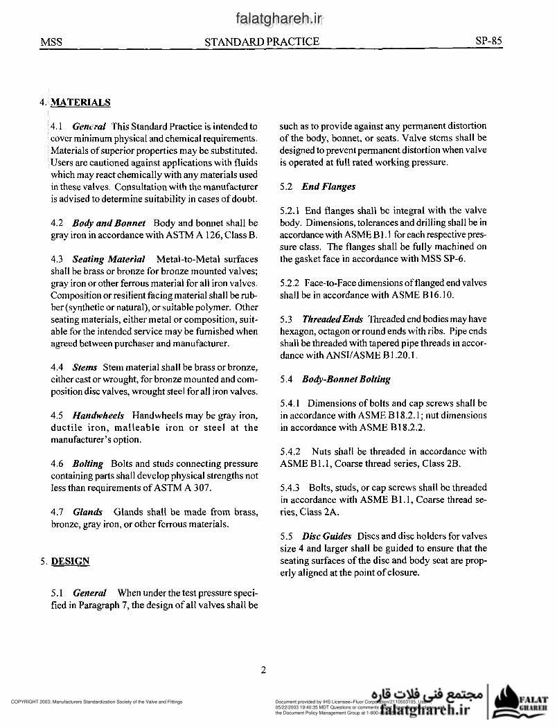
4.1 zyxwvutsrqponmlkjihgfedcbaZYXWVUTSRQPONMLKJIHGFEDCBAGenmzl This Standard Practice is intended to
cover minimum physical and chemical requirements.
Materials of superior properties may be substituted.
Users are cautioned against applications with fluids
which may react chemically with any materials used
in these valves. Consultation with the manufacturer
is advised to determine suitability in cases of doubt.
4.2 Body and Bonnet Body and bonnet shall be
gray iron in accordance with ASTM A 126, Class B.
4.3 Seating Material Metal-to-Metal surfaces
shall be brass or bronze for bronze mounted valves;
gray iron or other ferrous material for all iron valves.
Composition or resilient facing material shall be rub-
ber (synthetic or natural), or suitable polymer. Other
seating materiais, either metal or composition, suit-
able for the intended service may be furnished when
agreed between purchaser and manufacturer.
4.4 Stems Stem material shall be brass or bronze,
either cast or wrought, for bronze mounted and com-
position disc valves, wrought steel for all iron valves.
4.5 Handwheels Handwheels may be gray iron,
ductile iron, malleable iron or steel at the
manufacturer’s option.
4.6 Bolting Bolts and studs connecting pressure
containing parts shall develop physical strengths not
less than requirements of ASTM A 307.
4.7 Glands Glands shall be made from brass,
bronze, gray iron, or other ferrous materials.
5. DESIGN
such as to provide against any permanent distortion
of the body, bonnet, or seats. Valve stems shall be
designed to prevent permanent distortion when valve
is operated at full rated working pressure.
5.2 End Flanges
5.2.1 End flanges shall be integral with the valve
body. Dimensions, tolerances and drilling shall be in
accordance with ASME B 1.1 for each respective pres-
sure class. The flanges shall be fully machined on
the gasket face in accordance with MSS SP-6.
5.2.2 Face-to-Face dimensions of flanged end valves
shall be in accordance with ASME B 16.1 O.
5.3 ThreadedEnh Threaded end bodies may have
hexagon, octagon or round ends with ribs. Pipe ends
shall be threaded with tapered pipe threads in accor-
dance with ANSUASME B 1.20.1.
5.4 Body-Bonnet Bolting
5.4.1 Dimensions of bolts and cap screws shall be
in accordance with ASME B 18.2.1 zyxwvutsrqponmlkjihgfedcbaZYXWVUTSRQPONMLKJIHGFEDCBA; nut dimensions
in accordance with ASME B18.2.2.
5.4.2
ASME B 1.1, Coarse thread series, Class 2B.
Nuts shall be threaded in accordance with
5.4.3 Bolts, studs, or cap screws shall be threaded
in accordance with ASME B 1.1, Coarse thread se-
ries, Class zyxwvutsrqponmlkjihgfedcbaZYXWVUTSRQPONMLKJIHGFEDCBA2A.
5.5 Disc Guides Discs and disc holders for valves
size 4 and larger shall be guided to ensure that the
seating surfaces of the disc and body seat are prop-
erly aligned at the point of closure.
5.1 General When under the test pressure speci-
fied in Paragraph 7, the design of all valves shall be
2
COPYRIGHT 2003; Manufacturers Standardization Society of the Valve and Fittings
Document provided by IHS Licensee=Fluor Corporation/2110503105, User=, 05/22/2003 19:40:35 MDT Questions or comments about this message: please callthe Document Policy Management Group at 1-800-451-1584.
--```,`,,````,,,```,,,,`,`,,`,-`-`,,`,,`,`,,`---
www.b
zfx
w.c
om
falatghareh.irfalatghareh.ir
MSS STANDARD zyxwvutsrqponmlkjihgfedcbaZYXWVUTSRQPONMLKJIHGFEDCBAPRACTICE SP-85
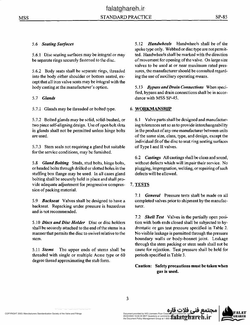
5.6 zyxwvutsrqponmlkjihgfedcbaZYXWVUTSRQPONMLKJIHGFEDCBASeating Surfaces
5.6.1 Disc seating surfaces may be integral or may
be separate rings securely fastened to the disc.
5.6.2 Body seats shall be separate rings, threaded
into the body either shoulder or bottom seated, ex-
cept that all iron valve seats may be integral with the
body casting at the manufacturer?s option.
5.7 Glands
5.7.1 Glands may be threaded or bolted type.
5.7.2 Bolted glands may be solid, solid-bushed, or
two piece self-aligning design. Use of open bolt slots
in glands shall not be permitted unless hinge bolts
are used.
5.7.3 Stem seals not requiring a gland but suitable
for the service conditions, may be furnished.
5.8 Gland Bolting Studs, stud bolts, hinge bolts,
or headed bolts through drilled or slotted holes in the
stuffing box flange may be used. In all cases gland
bolting shall be securely held in place and shall pro-
vide adequate adjustment for progressive compres-
sion of packing material.
5.9 Backseat Valves shall be designed to have a
backseat. Repacking under pressure is hazardous
and is not recommended. zyxwvutsrqponmlkjihgfedcbaZYXWVUTSRQPONMLKJIHGFEDCBA5.10 Discs and Disc Holder Disc or disc holders
shall be securely attached to the end of the stems in a
manner that permits the disc to swivel relative to the
stem.
5.11 Stems The upper ends of stems shall be
threaded with single or multiple Acme type or 60
degree thread approximating the stub form.
5.12 Handwheels Handwheels shall be of the
spoke type only. Webbed or disc type are not permit-
ted. Handwheels shall be marked with the direction
of movement for opening of the valve. On large size
valves to be used at or near maximum rated pres-
sures, the manufacturer should be consulted regard-
ing the use of auxiliary operating means.
5.13 BypassandDraìn Connectìons When speci-
fied, bypass and drain connections shall be in accor-
dance with MSS SP-45.
6. WORKMANSHIP
6.1 Valve parts shall be designed and manufactur-
ing tolerances set so as to provide interchangeability
in the product of any one manufacturer between units
of the same size, class, type, and design, except the
individual fit of the disc to seat ring seating surfaces
of Type I and II valves.
6.2 Castings All castings shall be clean and sound,
without defects which will impair their service. No
plugging, impregnation, welding, or repairing of such
defects will be allowed. zyxwvutsrqponmlkjihgfedcbaZYXWVUTSRQPONMLKJIHGFEDCBA7: TESTS
7.1 General Pressure tests shall be made on all
completed valves prior to shipment by the manufac-
turer.
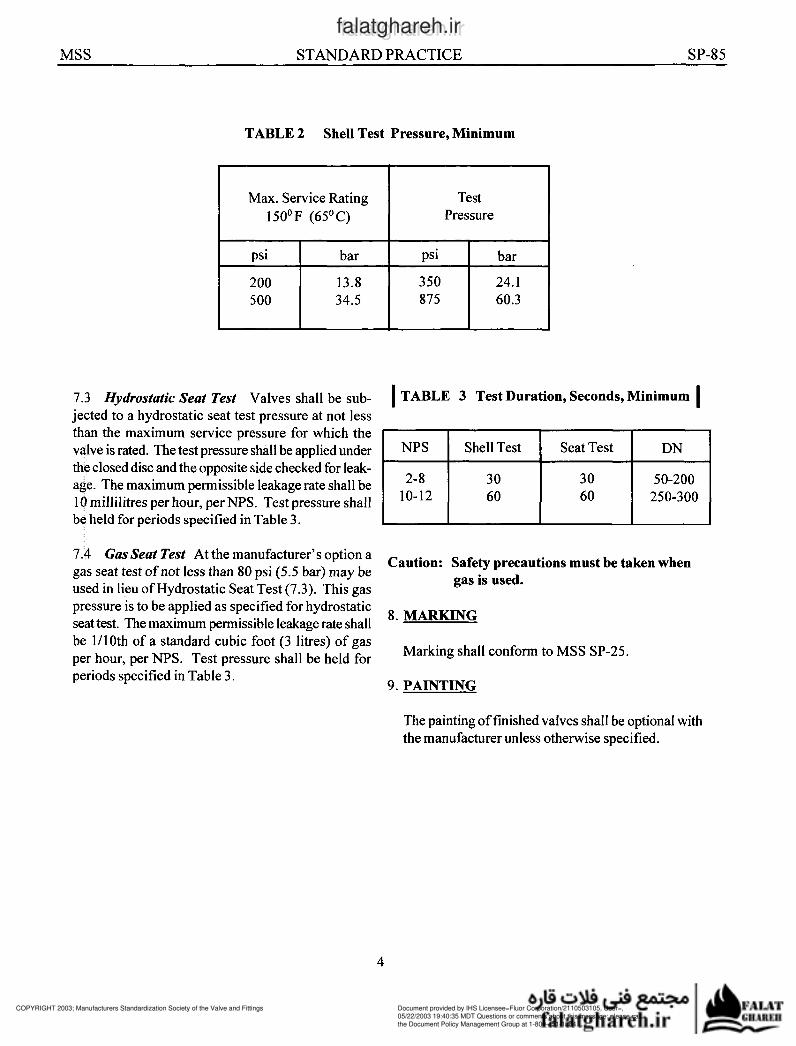
7.2 Shell Test Valves in the partially open posi-
tion with both ends closed shall be subjected to hy-
drostatic or gas test pressure specified in Table 2.
No visible leakage is permitted through the pressure
boundary walls or body-bonnet joint. Leakage
through the stem packing or stem seals shall not be
cause for rejection. Test pressure shall be held for
periods specified in Table 3.
Caution: Safety precautions must be taken when
gas is used.
3
COPYRIGHT 2003; Manufacturers Standardization Society of the Valve and Fittings
Document provided by IHS Licensee=Fluor Corporation/2110503105, User=, 05/22/2003 19:40:35 MDT Questions or comments about this message: please callthe Document Policy Management Group at 1-800-451-1584.
--```,`,,````,,,```,,,,`,`,,`,-`-`,,`,,`,`,,`---www.b
zfx
w.c
om
falatghareh.irfalatghareh.ir
MSS zyxwvutsrqponmlkjihgfedcbaZYXWVUTSRQPONMLKJIHGFEDCBASTANDARD PRACTICE SP-85
2-8
10-12
TABLE 2 Shell Test Pressure, Minimum
30 30 50-200
60 60 250-300 zyxwvutsrqponmlkjihgfedcbaZYXWVUTSRQPONMLKJIHGFEDCBA
I I I Max. Service Rating
150°F (65°C)
Test
Pressure
200 13.8 350 24.1
34.5 60.3
7.3 zyxwvutsrqponmlkjihgfedcbaZYXWVUTSRQPONMLKJIHGFEDCBAHydrostatìc Seat Test Valves shall be sub-
jected to a hydrostatic seat test pressure at not less
than the maximum service pressure for which the
valve is rated. The test pressure shall be applied under
the closed disc and the opposite side checked for leak-
age. The maximum permissible leakage rate shall be
1 O millilitres per hour, per NPS. Test pressure shall be held for periods specified in Table 3.
7.4 Gus Seat Test At the manufacturer’s option a
gas seat test of not less than 80 psi (5.5 bar) may be
used in lieu of Hydrostatic Seat Test (7.3). This gas
pressure is to be applied as specified for hydrostatic
seat test. The maximum permissible leakage rate shall
be Moth of a standard cubic foot (3 litres) of gas
per hour, per NPS. Test pressure shall be held for
periods specified in Table 3.
I TABLE 3 Test Duration, Seconds, Minimum I
I NPS I ShellTest I SeatTest I DN I
Caution: Safety precautions must be taken when
gas is used.
8. MARKING
Marking shall conform to MSS SP-25.
9. PAINTING
The painting of finished valves shall be optional with
the manufacturer unless otherwise specified. zyxwvutsrqponmlkjihgfedcbaZYXWVUTSRQPONMLKJIHGFEDCBA
4
COPYRIGHT 2003; Manufacturers Standardization Society of the Valve and Fittings
Document provided by IHS Licensee=Fluor Corporation/2110503105, User=, 05/22/2003 19:40:35 MDT Questions or comments about this message: please callthe Document Policy Management Group at 1-800-451-1584.
--```,`,,````,,,```,,,,`,`,,`,-`-`,,`,,`,`,,`---
www.b
zfx
w.c
om
falatghareh.irfalatghareh.ir
MSS zyxwvutsrqponmlkjihgfedcbaZYXWVUTSRQPONMLKJIHGFEDCBASTANDARD PRACTICE SP-85
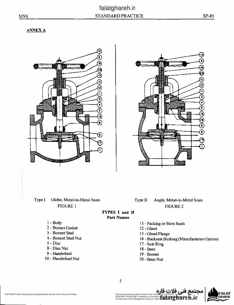
ANNEX A
Type I Globe, Metal-to-Metal Seats
FIGURE 1
TYPES I and II
Part Names
1 -Body
2 zyxwvutsrqponmlkjihgfedcbaZYXWVUTSRQPONMLKJIHGFEDCBA- Bonnet Gasket zyxwvutsrqponmlkjihgfedcbaZYXWVUTSRQPONMLKJIHGFEDCBA3 - Bonnet Stud
4 - Bonnet Stud Nut zyxwvutsrqponmlkjihgfedcbaZYXWVUTSRQPONMLKJIHGFEDCBA5 - Disc
8 - Disc Nut
9 - Handwheel
10 - Handwheel Nut
Type II Angle, Metal-to-Metal Seats
FIGURE 2
1 1 -Packing or Stem Seals
12 - Gland
13 - Gland Flange
16 - Backseat Bushing (Manufacturers Option)
17 - Seat Ring
18 - Stem
19 - Bonnet
20 - Stem Nut zyxwvutsrqponmlkjihgfedcbaZYXWVUTSRQPONMLKJIHGFEDCBA5
COPYRIGHT 2003; Manufacturers Standardization Society of the Valve and Fittings
Document provided by IHS Licensee=Fluor Corporation/2110503105, User=, 05/22/2003 19:40:35 MDT Questions or comments about this message: please callthe Document Policy Management Group at 1-800-451-1584.
--```,`,,````,,,```,,,,`,`,,`,-`-`,,`,,`,`,,`---
www.b
zfx
w.c
om
falatghareh.irfalatghareh.ir
MSS STANDARD zyxwvutsrqponmlkjihgfedcbaZYXWVUTSRQPONMLKJIHGFEDCBAPRACTICE SP-85
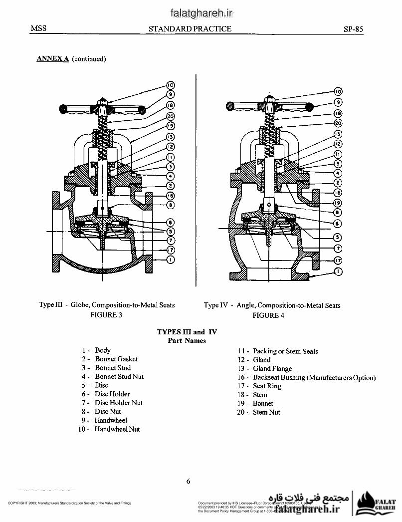
ANNEX A (continued)
Type III zyxwvutsrqponmlkjihgfedcbaZYXWVUTSRQPONMLKJIHGFEDCBA- Globe, Composition-to-Metal Seats
FIGURE 3
1 - Body
2 - Bonnet Gasket
3 - Bonnet Stud
4 - Bonnet Stud Nut
6 - Disc Holder
7 - Disc Holder Nut
8 - DiscNut
9 - Handwheel
5 - Disc
1 zyxwvutsrqponmlkjihgfedcbaZYXWVUTSRQPONMLKJIHGFEDCBAO - Handwheel Nut
Type IV - zyxwvutsrqponmlkjihgfedcbaZYXWVUTSRQPONMLKJIHGFEDCBAAngle,.Composition-to-Metal Seats
FIGURE 4
TYPES III and IV
Part Names
1 1 - Packing or Stem Seals
13 - Gland Flange
16 - Backseat Bushing (Manufacturers Option)
17 - Seat Ring
18 - Stem
19 - Bonnet
20 - StemNut
12 - Gland
6
COPYRIGHT 2003; Manufacturers Standardization Society of the Valve and Fittings
Document provided by IHS Licensee=Fluor Corporation/2110503105, User=, 05/22/2003 19:40:35 MDT Questions or comments about this message: please callthe Document Policy Management Group at 1-800-451-1584.
--```,`,,````,,,```,,,,`,`,,`,-`-`,,`,,`,`,,`---www.b
zfx
w.c
om
falatghareh.irfalatghareh.ir
MSS STANDARD zyxwvutsrqponmlkjihgfedcbaZYXWVUTSRQPONMLKJIHGFEDCBAPRACTICE SP-85
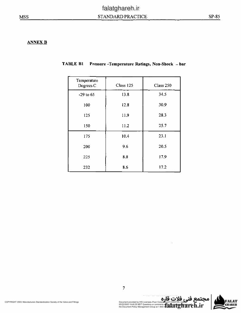
Temperature
Degrees C
-29 to 65
1 O0
125
150
175
200
225
232
ANNEX B
Class 125 Class 250
13.8 34.5
12.8 30.9
11.9 28.3
11.2 25.7
10.4 23.1
9.6 20.5
8.8 17.9
8.6 17.2
TABLE B1 Pressure -Temperature Ratings, Non-Shock zyxwvutsrqponmlkjihgfedcbaZYXWVUTSRQPONMLKJIHGFEDCBA- bar
7
COPYRIGHT 2003; Manufacturers Standardization Society of the Valve and Fittings
Document provided by IHS Licensee=Fluor Corporation/2110503105, User=, 05/22/2003 19:40:35 MDT Questions or comments about this message: please callthe Document Policy Management Group at 1-800-451-1584.
--```,`,,````,,,```,,,,`,`,,`,-`-`,,`,,`,`,,`---www.b
zfx
w.c
om
falatghareh.irfalatghareh.ir
MSS zyxwvutsrqponmlkjihgfedcbaZYXWVUTSRQPONMLKJIHGFEDCBASTANDARD PRACTICE SP-85
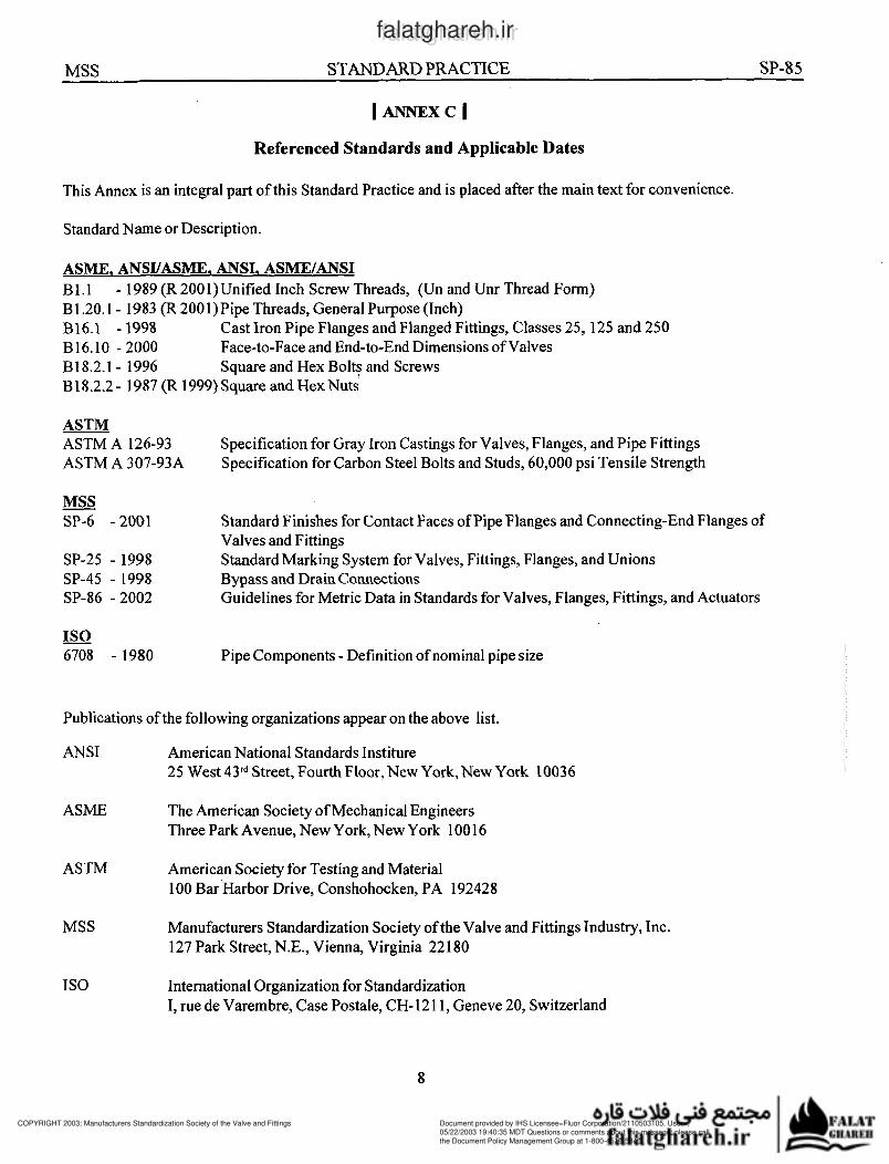
I A N N E X C I
Referenced Standards and Applicable Dates
This Annex is an integral part of this Standard Practice and is placed after the main text for convenience.
Standard Name or Description.
ASME. ANSUASME. ANSI. ASME/ANSI
B 1.1
B1.20.1- 1983 (R 2001)Pipe Threads, General Purpose (Inch)
B16.1 -1998
B16.10 -2000
B18.2.1- 1996
B18.2.2- i987 (R 1999) Square and HexNuts zyxwvutsrqponmlkjihgfedcbaZYXWVUTSRQPONMLKJIHGFEDCBA- 1989 (R 200 1) Unified Inch Screw Threads, (Un and Unr Thread Form)
Cast Iron Pipe Flanges and Flanged Fittings, Classes 25, 125 and 250
Face-to-Face and End-to-End Dimensions of Valves
Square and Hex Bolts and Screws
ASTM ASTM A 126-93
ASTM A 307-93A
Specification for Gray Iron Castings for Valves, Flanges, and Pipe Fittings
Specification for Carbon Steel Bolts and Studs, 60,000 psi Tensile Strength
- MSS SP-6 -2001
SP-25 - 1998
SP-45 - 1998 SP-86 -2002
Standard Finishes €or Contact Faces of Pipe Flanges and Connecting-End Flanges of
Valves and Fittings
Standard Marking System for Valves, Fittings, Flanges, and Unions Bypass and Drain Connections
Guidelines for Metric Data in Standards for Valves, Flanges, Fittings, and Actuators
- IS0
6708 - 1980 Pipe Components - Definition of nominal pipe size
Publications of the following organizations appear on the above list.
ANSI American National Standards Institure
25 West 43rd Street, Fourth Floor, New York,New York 10036
ASME The American Society of Mechanical Engineers
Three Park Avenue, New York, New York 1 zyxwvutsrqponmlkjihgfedcbaZYXWVUTSRQPONMLKJIHGFEDCBAO0 16
ASTM American Society for Testing and Material
1 O0 Bar Harbor Drive, Conshohocken, PA 192428
MSS Manufacturers Standardization Society of the Valve and Fittings Industry, Inc.
127 Park Street, N.E., Vienna, Virginia 22 180
IS0 International Organization for Standardization
I, rue de Varembre, Case Postale, CH- 12 1 1, Geneve 20, Switzerland
8
COPYRIGHT 2003; Manufacturers Standardization Society of the Valve and Fittings
Document provided by IHS Licensee=Fluor Corporation/2110503105, User=, 05/22/2003 19:40:35 MDT Questions or comments about this message: please callthe Document Policy Management Group at 1-800-451-1584.
--```,`,,````,,,```,,,,`,`,,`,-`-`,,`,,`,`,,`---
www.b
zfx
w.c
om
falatghareh.irfalatghareh.ir
Number SP-6-2001 SP-9-2001 SP-25-1998 SP-42-1999 SP43-1991 SP-44-1996 SP-45-1998 SP-51-2000 SP-53-1999
SP-54-1999 zyxwvutsrqponmlkjihgfedcbaZYXWVUTSRQPONMLKJIHGFEDCBAS P-55-200 1
SP-58-1993 SP-60-1999 SP-61-1999 SP-65-1999 SP-67-2002 SP-68-1997 SP-69-2002 SP-70-1998 SP-71-1997 SP-72-1999 SP-73-1991 SP-75-1998 SP-77- 1995 SP-78-1998
SP-80-1997 SP-81-2001 SP-82-1992 SP-83-2001 SP-85-2002
SP-79-1999a
SP-86-2002 SP-88-1993 SP-89-1998 sP-90-2000 SP-91-1992 SP-92-1999 SP-93-1999
SP-94-1999
SP-95-2000 SP-96-2001 S P-97-200 1
SP-98-2001 SP-99-1994 sP-100-2002 SP-1 O 1 -1 989 SP-102-1969 SP-103-1995 SP-104-1995 SP-105-1996 SP-106-1990 SP-107-1991 SP-108-2002 SP-109-1997 SP-110-1996 sP-111-2001 SP-112-1999
SP-113-2001 SP-114-2001 SP-115-1999 SP-I 16-1996 SP-117-2002 SP-118-2002 SP-119-1996 SP-120-2002 SP-121-1997 SP-122-1997 SP-123-1998 SP-124-2001 SP-125-2000 SP-126-2000 SP-127-2001
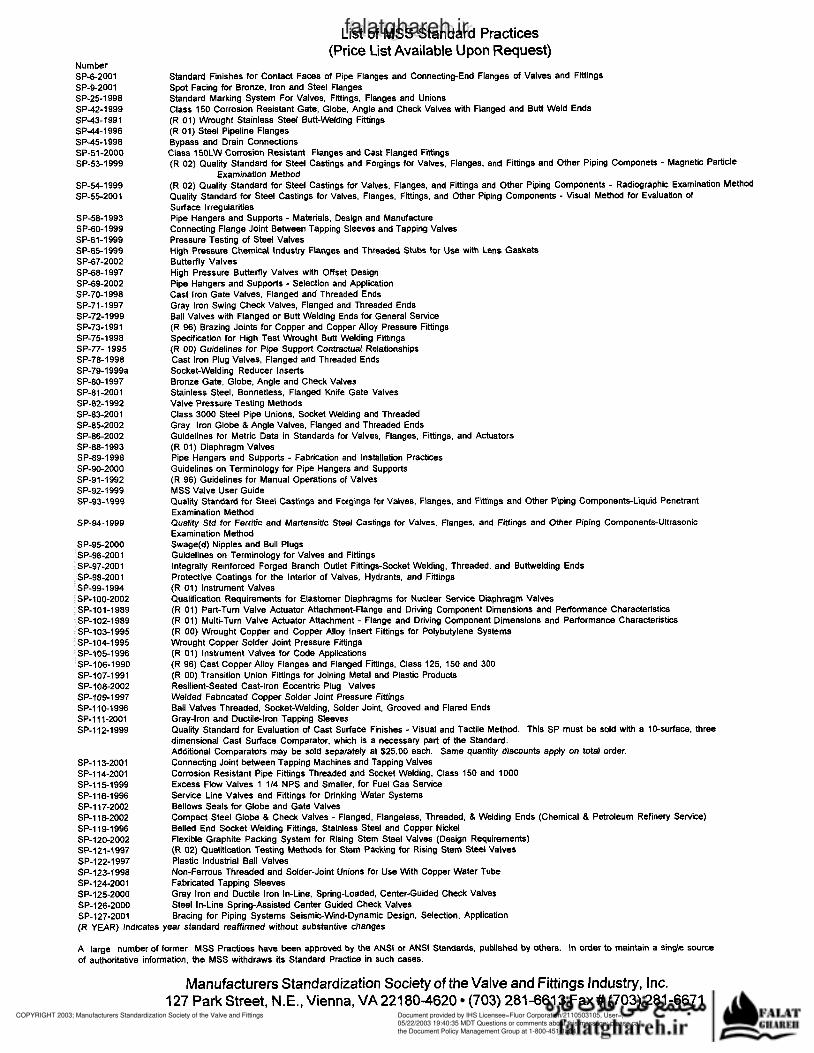
List of MSS Standard Practices (Price List Available Upon Request)
Standard Finishes for Contact Faces of Pipe Flanges and Connecting-End Flanges of Valves and Ftungs Spot Facing for Bronze, Iron and Steel Flanges Standard Marking System For Valves, Fittings. Flanges and Unions Class 150 Corrosion Resistant Gate, Globe, Angle and Check Valves with Flanged and Butt Weld Ends (R 01) Wrought Stainless Steel Butt-Welding Fittings (R 01) Steel Pipeline Flanges Bypass and Drain Connections Class 150LW Corrosion Resistant Flanges and Cast Flanged Fittings (R 02) Quality Standard for Steel Castings and Forgings for Valves, Flanges, and Fittings and Other Piping Componets - Magnetic Partide
(R 02) Quality Standard for Steel Castings for Valves, Flanges, and Fittings and Other Piping Components - Radiographic Examination Method Quality Standard for Steel Castings for Valves, Flanges, Fittings. and Other Piping Components - Visual Method for Evaluation of Surface Irregularities Pipe Hangers and Supports - Materials, Design and Manufacture Connecting Flange Joint Between Tapping Sleeves and Tapping Valves Pressure Testing of Steel Valves High Pressure Chemical Industry Flanges and Threaded Stubs for Use with Lens Gaskets Butterfly Valves High Pressure Butterfly Valves with Offset Design Pipe Hangers and Supports - Selection and Application Cast Iron Gate Valves, Flanged and Threaded Ends Gray Iron Swing Check Valves, Flanged and Threaded Ends Ball Valves with Flanged or Butt Welding Ends for General Service (R 96) Brazing Joints for Copper and Copper Alloy Pressure Fittings Specification for High Test Wrought Butt Welding Fittings (R 00) Guidelines for Pipe Support Contractual Relationships Cast Iron Plug Valves, Flanged and Threaded Ends Socket-Welding Reducer Inserts Bronze Gate, Globe, Angle and Check Valves Stainless Steel, Bonnetless. Flanged Knife Gate Valves Valve Pressure Testing Methods Class 3000 Steel Pipe Unions, Socket Welding and Threaded Gray Iron Globe zyxwvutsrqponmlkjihgfedcbaZYXWVUTSRQPONMLKJIHGFEDCBA8 Angle Valves, Flanged and Threaded Ends Guidelines for Metric Data in Standards for Valves, Flanges, Fittings, and Actuators (R 01) Diaphragm Valves Pipe Hangars and Supports - Fabrication and Installation Practices Guidelines on Terminology for Pipe Hangers and Supports (R 96) Guidelines for Manual Operations of Valves MSS Valve User Guide Quality Standard for Steel Castings and Forgings for Valves, Flanges, and Fittings and Other Piping Components-Liquid Penetrant Examination Method Quality Std for Ferritic and Martensiüc Steel Castings for Valves, Flanges, and Fittings and Other Piping Components-Ultrasonic Examination Method Swage(d) Nipples and Bull Plugs Guidelines on Terminology for Valves and Fittings Integrally Reinforced Forged Branch Outlet Fittings-Socket Welding, Threaded, and Buttwelding Ends Protective Coatings for the Interior of Valves, Hydrants, and Fittings (R 01) Instrument Valves Qualification Requirements for Elastomer Diaphragms for Nuclear Service Diaphragm Valves (R 01) Part-Turn Valve Actuator Attachment-Flange and Driving Component Dimensions and Performance Characteristics (R 01) Multi-Turn Valve Actuator Attachment - Flange and Driving Component Dimensions and Performance Characteristics (R 00) Wrought Copper and Copper Alloy Insert Fittings for Polybutylene Systems Wrought Copper Solder Joint Pressure Fittings (R 01) Instrument Valves for Code Applications (R 96) Cast Copper Alloy Flanges and Flanged Fittings, Class 125, 150 and 300 (R 00) Transition Union Fittings for Joining Metal and Plastic Products Resilient-Seated Cast-Iron Eccentric Plug Valves Welded Fabricated Copper Solder Joint Pressure Fittings Ball Valves Threaded, Socket-Welding, Solder Joint, Grooved and Flared Ends Gray-Iron and Ductilelron Tapping Sleeves Quality Standard for Evaluation of Cast Surface Finishes - Visual and Tactile Method. This SP must be sold with a IO-surface, three dimensional Cast Surface Comparator, which is a necessary part of the Standard. Additional Comparators may zyxwvutsrqponmlkjihgfedcbaZYXWVUTSRQPONMLKJIHGFEDCBAbe sold separately at $25.00 each. Same quant¡¡ discounts apply on total order. Connecting Joint between Tapping Machines and Tapping Valves Corrosion Resistant Pipe Fittings Threaded and Socket Welding, Class 150 and 1000 Excess Flow Valves 1 1/4 NPS and Smaller, for Fuel Gas Service Service Line Valves and Fittings for Drinking Water Systems Bellows Seals for Globe and Gate Valves Compact Steel Globe & Check Valves - Flanged, Flangeless, Threaded, & Welding Ends (Chemical & Petroleum Refinery Service) Belled End Socket Welding Fittings, Stainless Steel and Copper Nickel Flexible Graphite Packing System for Rising Stem Steel Valves (Design Requirements) (R 02) Qualficatin Testing Methods for Stem Packing for Rising Stem Steel Valves Plastic Industrial Ball Valves Non-Ferrous Threaded and Solder-Joint Unions for Use zyxwvutsrqponmlkjihgfedcbaZYXWVUTSRQPONMLKJIHGFEDCBAWith Copper Water Tube Fabricated Tapping Sleeves Gray Iron and Ductile Iron In-Line, Spring-Loaded, Center-Guided Check Valves Steel In-Line Spring-Assisted Center Guided Check Valves Bracing for Piping Systems Seismic-Wind-Dynamic Design, Selection, Application
Examination Method
(R YEAR) Indicates year standard reaffirmed without substantive changes
A large number of former MSS Practices have been approved by the ANSI or ANSI Standards, published by others. In order to maintain a single source
of authoritative information, the MSS withdraws its Standard Practice in such cases.
Manufacturers Standardization Society of the Valve and Fittings Industry, Inc. 127 Park Street, N.E., Vienna, VA22180-4620 (703) 281-6613 Fax# (703) 281-6671
COPYRIGHT 2003; Manufacturers Standardization Society of the Valve and Fittings
Document provided by IHS Licensee=Fluor Corporation/2110503105, User=, 05/22/2003 19:40:35 MDT Questions or comments about this message: please callthe Document Policy Management Group at 1-800-451-1584.
--```,`,,````,,,```,,,,`,`,,`,-`-`,,`,,`,`,,`---
www.b
zfx
w.c
om
falatghareh.irfalatghareh.ir