Embed Size (px)
Citation preview
I
OQ
crs
OQ
Mechanism of Gravity
Drainage and Its Relation
to Specific Yield of
Uniform Sands
GEOLOGICAL SURVEY PROFESSIONAL PAPER 402-A
Mechanism of Gravity
Drainage and Its Relation
to Specific Yield of
Uniform SandsBy W. O. SMITH
INFILTRATION AND DRAINAGE IN UNIFORM SANDS
GEOLOGICAL SURVEY PROFESSIONAL PAPER 402-A
UNITED STATES GOVERNMENT PRINTING OFFICE, WASHINGTON : 1961
UNITED STATES DEPARTMENT OF THE INTERIOR
STEWART L. UDALL, Secretary
GEOLOGICAL SURVEY
Thomas B. Nolan, Director
For sale by the Superintendent of Documents, U.S. Government Printing Office Washington 25, D.C. - Price 20 cents (paper cover)
CONTENTS
Page Abstract.,_ _________________________________________ A-lIntroduction _______________________________________ 1The mechanism of gravity drainage ___________________ 1Nature and formation of retained liquid masses_______ 3Calculation of retention and yield___________________ 5Experiments of F. H. King and Alien Hazen___________ 8
PageCalculation of specific yield from pumping-test data____ A-llRelation of moisture equivalent to specific yield._______Thermodynamic relations of capillary surfaces__________Water drive in an oil-bearing sand_____-_-_-____-____.Summary_____ _____________________________________References cited____________________________________
1111121212
ILLUSTRATIONS
Page FIGURE 1. Schematic diagram of apparatus used to drain a uniform sand__---_--___--_-___-_-___--_-------____-_-__- A-2
2. Types of capillary water present in an unsaturated sand_-_-----_-__------------------------_------_---_- 23. Development of maximum capillary rise meniscus______________________________________________________ 34. Formation of pendular body by detachment from maximum capillary rise meniscus_________________________ 45. Formation of funicular body by detachment from maximum capillary rise meniscus_________________________ 46. Drainage relations of a cylindrical column of sand__________________-_-__--_-___-_____-_---__-_____-_ _ 77. Curve showing the yield (1 fi/P), in the unsaturated region, as a function of the porosity P of a uniform sand_ 88. Retention curves for F. H. King's sands________-_______--__--_____-_--------__---_______-------______ 109. Thermodynamic relations of capillary grain water_____________________________________________________ 12
TABLES
Page TABLE 1. Summary of data on King's sands. A, Initial packing and water content; B, Zone data (water)_____________ A-8
2. Summary of observed and calculated values on drainage, retention, and specific yield for King's sands. A, Resultsfor water; B, Calculated values, for petroleum___________________________________________ __________ 9
3. Data on and specific yield of Hazen's sands (water)_____________________________________--_-____--_---_- 11m

INFILTRATION AND DRAINAGE IN UNIFORM SANDS
MECHANISM OF GRAVITY DRAINAGE AND ITS RELATION TO SPECIFIC YIELD OF UNIFORM SANDS
By W. O. SMITH
ABSTRACT
The capillary theory of retention of water and of drainage under a gravity of 1 is developed for uniform sands. It is shown that the meniscus enclosing the water bodies retained in the sand is broken off from the meniscus of maximum capillary rise as it falls through the sand. Quantitative expressions for the specific yield of a uniform sand also are derived. It is shown that the initial drainage under a maximum capillary rise meniscus accounts for the bulk of the drained water. The data of F. H. King and of Alien Hazen are analyzed; the results were in good agreement with the theory as developed in this report. Com parative calculations are given for crude petroleum. The problem of water drive in an oil-bearing sand is discussed briefly on the assumption that the capillary bodies of oil retained are initially formed by the oil-water interface as it passes through the sand.
INTRODUCTION
The recovery of liquid from an initially saturated porous rock depends not only on the architecture of the pore space and the nature of the minerals constituting the rock but also on the process used to recover the liquid. The physical properties of the liquid add a complication. Whenever an attempt is made to drain a given rock of its saturating liquid, mechanisms which retain the liquid become operative, and generally only a part of the liquid can be withdrawn.
Retention mechanisms depend largely on the process used to drain the rock. For example, if a loose sand, fully saturated with water, is freed of its stored liquid by heating to a temperature just above the boiling point, recovery will be 100 percent; all the water will be boiled off and may be collected. If, however, the sand is drained under a field of 1-gravity, capillary retention becomes operative and only a part of the liquid may be recovered. From a saturated clay, water may be removed by heating, and it will be not only absorbed water but perhaps water of combination, according to the temperature; and the clay may even be changed irreversibly. If, however, a field of 1-gravity is used to drain the clay, ordinarily little or no water can be recovered.
In ground-water aquifers and petroleum reservoirs, gravity drainage is an important process. In this report the subject matter will generally be limited to uniform sands. In particular it will be shown how to calculate the specific yield of a uniform sand. This quantity is important in ground-water hydrology and has been defined by Meinzer (1923, p. 51) as the amount of water which, under a force field of 1-gravity, will drain out of a unit volume of a saturated rock. Unsorted sands and those which do not approximate spherical grams will not be considered, since this would require extended investigation. It will be shown that the retention mechanism is capillarity, and that water held by surface absorption or other agencies is negligible. To understand this quantity and to arrive at a quantita tive expression, it is necessary to examine in some detail the gravity-drainage process in rocks.
THE MECHANISM OF GRAVITY DRAINAGE
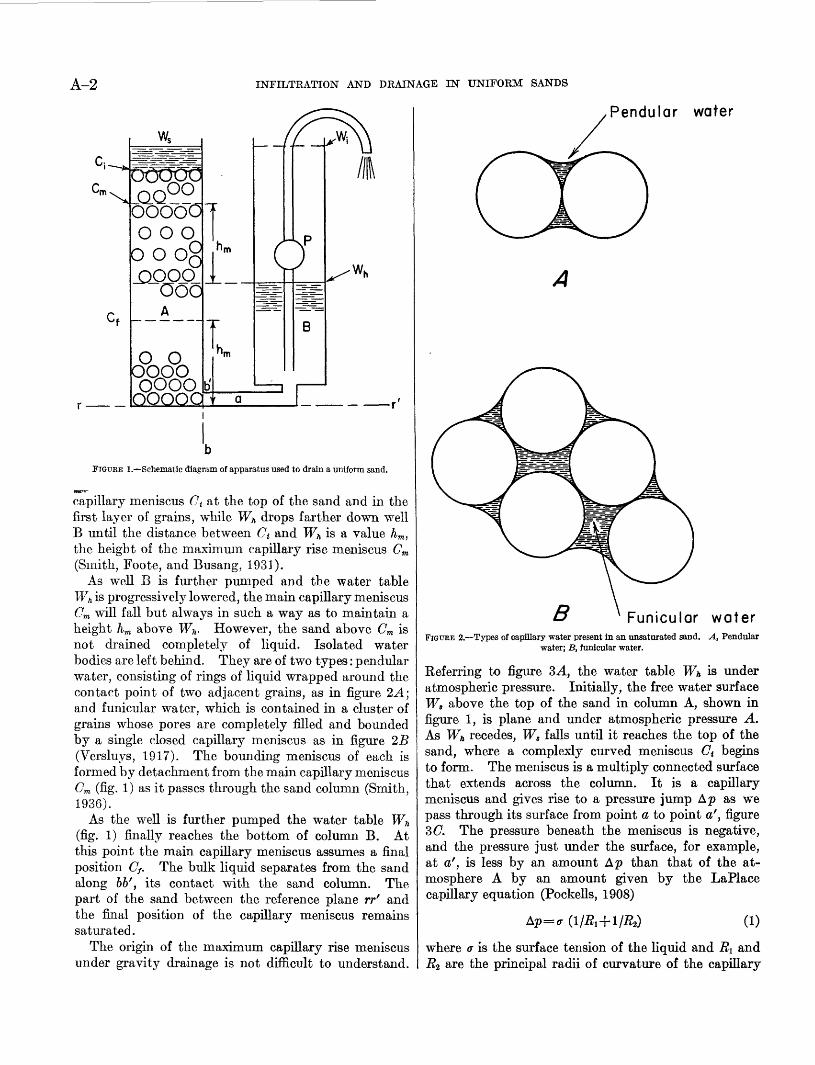
For the purpose of understanding the ordinary gravity-drainage mechanism, let us consider a long column of uniform sand packed in column A as shown in figure 1. Let column A be joined to column B by tube a. Column B contains liquid only, and is sufficiently wide that surface-tension effects at the free liquid surface Wn are negligible. Column B will serve as a well and P as a pump which is used to remove liquid. Wn in actual practice is the water table or phreatic surface.
Suppose the sand column A is fully packed to within an inch or more of the top, that all pores are completely filled with water, and that the liquid initially forms a free surface Ws just above the packing. The initial water table Wt in well B will occupy a position Wt in such a manner that Ws and Wt are at equal heights above the reference plane rr'. When pump P is started water will be removed from column B and Wt will fall. In column A, the sand column Ws will fall until it reaches the top of the sand. There it will form a
A-l
A-2 INFILTRATION AND DRAINAGE IN UNIFORM SANDS
Ci--*
Cm\ ^*.
Cf
Q0°°ooooo o o o
0 0 0§ _QOOO
000A
o o0000oooo
j
.' ,'b
L
hm
'
,
(z=^r
i
-\
B
^
f _
FIGURE 1. Schematic diagram of apparatus used to drain a uniform sand.
capillary meniscus Ct at the top of the sand and in the first layer of grains, while Wh drops farther down well B until the distance between Ct and Wh is a value hm , the height of the maximum capillary rise meniscus Gm (Smith, Foote, and Busang, 1931).
As well B is further pumped and the water table Wh is progressively lowered, the main capillary meniscus Cm will fall but always in such a way as to maintain a height hm above W& However, the sand above Cm is not drained completely of liquid. Isolated water bodies are left behind. They are of two types: pendular water, consisting of rings of liquid wrapped around the contact point of two adjacent grains, as in figure 2 A; and funicular water, which is contained in a cluster of grains whose pores are completely filled and bounded by a single closed capillary meniscus as in figure 2B (Versluys, 1917). The bounding meniscus of each is formed by detachment from the main capillary meniscus Cm (fig. 1) as it passes through the sand column (Smith, 1936).
As the well is further pumped the water table Wh (fig. 1) finally reaches the bottom of column B. At this point the main capillary meniscus assumes a final position Cf. The bulk liquid separates from the sand along bbf , its contact with the sand column. The part of the sand between the reference plane rrr and the final position of the capillary meniscus remains saturated.
The origin of the maximum capillary rise meniscus under gravity drainage is not difficult to understand.
Pendular water
Funicular waterFIGURE 2. Types of capillary water present in an unsaturated sand. A, Pendular
water; B, funicular water.
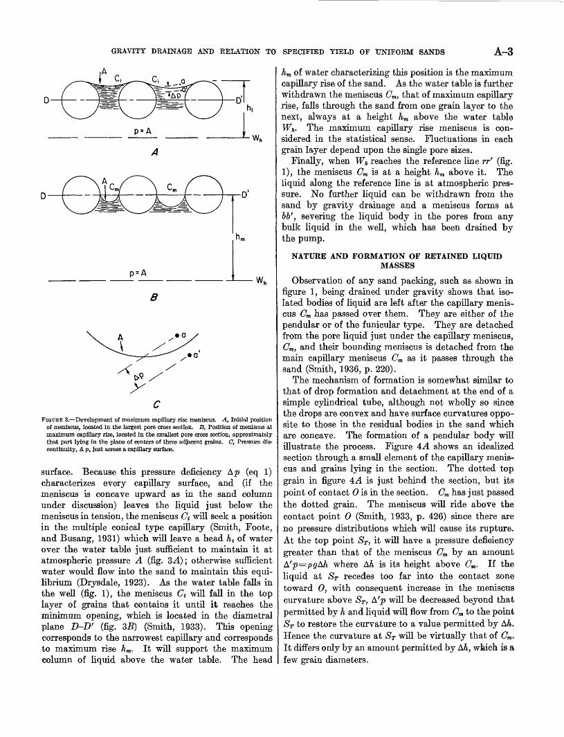
Referring to figure 3A, the water table Wh is under atmospheric pressure. Initially, the free water surface Ws above the top of the sand in column A, shown in figure 1, is plane and under atmospheric pressure A. As Wh recedes, Ws falls until it reaches the top of the sand, where a complexly curved meniscus C{ begins to form. The meniscus is a multiply connected surface that extends across the column. It is a capillary meniscus and gives rise to a pressure jump Ap as we pass through its surface from point a to point a', figure 3(7. The pressure beneath the meniscus is negative, and the pressure just under the surface, for example, at a', is less by an amount Ap than that of the at mosphere A by an amount given by the LaPlace capillary equation (Pockells, 1908)
Ap=ff (l/Ri+l/R^ (1)
where a is the surface tension of the liquid and RI and R2 are the principal radii of curvature of the capillary
GRAVITY DRAINAGE AND RELATION TO SPECIFIED YIELD OF UNIFORM SANDS A-3
p = A
FIGURE 3. Development of maximum capillary rise meniscus. A, Initial position of meniscus, located in the largest pore cross section. B, Position of meniscus at maximum capillary rise, located in the smallest pore cross section, approximately that part lying in the plane of centers of three adjacent grains. C, Pressure dis continuity, A p, just across a capillary surface.
surface. Because this pressure deficiency Ap (eq 1) characterizes every capillary surface, and (if the meniscus is concave upward as in the sand column under discussion) leaves the liquid just below the meniscus in tension, the meniscus Ct will seek a position in the multiple conical type capillary (Smith, Foote, and Busang, 1931) which will leave a head A< of water over the water table just sufficient to maintain it at atmospheric pressure A (fig. 3-4); otherwise sufficient water would flow into the sand to maintain this equi librium (Drysdale, 1923). As the water table falls in the well (fig. 1), the meniscus Ct will fall in the top layer of grains that contains it until it reaches the minimum opening, which is located hi the diametral plane D-D' (fig. 35) (Smith, 1933). This opening corresponds to the narrowest capillary and corresponds to maximum rise hm. It will support the maximum column of liquid above the water table. The head
hm of water characterizing this position is the maximum capillary rise of the sand. As the water table is further withdrawn the meniscus Cm, that of maximum capillary rise, falls through the sand from one grain layer to the next, always at a height hm above the water table Wn. The maximum capillary rise meniscus is con sidered in the statistical sense. Fluctuations in each grain layer depend upon the single pore sizes.
Finally, when Wn reaches the reference line rr' (fig. 1), the meniscus Cm is at a height hm above it. The liquid along the reference line is at atmospheric pres sure. No further liquid can be withdrawn from the sand by gravity drainage and a meniscus forms at 66', severing the liquid body in the pores from any bulk liquid in the well, which has been drained by the pump.
NATURE AND FORMATION OF RETAINED LIQUIDMASSES
Observation of any sand packing, such as shown in figure 1, being drained under gravity shows that iso lated bodies of liquid are left after the capillary menis cus Cm has passed over them. They are either of the pendular or of the funicular type. They are detached from the pore liquid just under the capillary meniscus, Cm, and their bounding meniscus is detached from the main capillary meniscus Cm as it passes through the sand (Smith, 1936, p. 220).
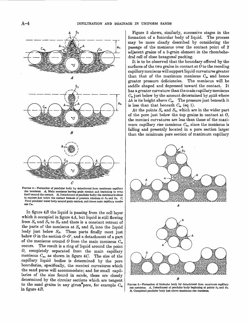
The mechanism of formation is somewhat similar to that of drop formation and detachment at the end of a simple cylindrical tube, although not wholly so since the drops are convex and have surface curvatures oppo site to those in the residual bodies in the sand which are concave. The formation of a pendular body will illustrate the process. Figure 4A shows an idealized section through a small element of the capillary menis cus and grains lying in the section. The dotted top grain in figure 4A is just behind the section, but its point of contact 0 is in the section. Cm has just passed the dotted grain. The meniscus will ride above the contact point 0 (Smith, 1933, p. 426) since there are no pressure distributions which will cause its rupture. At the top point ST, it will have a pressure deficiency greater than that of the meniscus Cm by an amount A'p=pgAJi where A/& is its height above Cm. If the liquid at ST recedes too far into the contact zone toward 0, with consequent increase in the meniscus curvature above ST, A'p will be decreased beyond that permitted by h and liquid will flow from Cm to the point ST to restore the curvature to a value permitted by Ah. Hence the curvature at ST will be virtually that of Cm- It differs only by an amount permitted by Aft, which is a few grain diameters.
A-4 INFILTRATION AND DRAINAGE IN UNIFORM SANDS
B
FIGUEE 4. Formation of pendular body by detachment from maximum capillary rise meniscus. A, Main meniscus leaving grain contact and beginning to wrap itself around the contact. JB, Detachment of pendular body; the meniscus is about to rupture just below the contact because of pressure relations at S, and St. C, Final pendular water body around grain contact, and above main capillary menis cus Cm.
In figure 4B the liquid is passing from the cell layer which it occupied in figure 4A, but liquid is still flowing from Sa and S> to ST and there is a constant retreat of the parts of the meniscus at Sa and Sj, into the liquid body just below ST. These parts finally meet just below 0 in the section 0-0', and a detachment of a part of the meniscus around 0 from the main meniscus Cm occurs. The result is a ring of liquid around the point 0, completely separated from the main capillary meniscus Cm) as shown in figure 4(7. The size of the capillary liquid bodies is determined by the pore boundaries, specifically, the menisci curvatures which the sand pores will accommodate; and for small capil laries of the size found in sands, these are closely determined by the circular sections which are tangent to the sand grains in any given*pore, for example Gm in figure 4B.
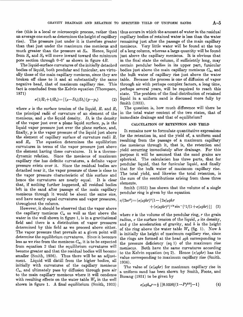
Figure 5 shows, similarly, successive stages in the formation of a funicular body of liquid. The process may be more clearly described by considering the passage of the meniscus over the contact point of 2 adjacent grains of a 3-grain element in the rhombohe- dral cell of close hexagonal packing.
It is to be observed that the boundary offered by the surfaces of the two grains in contact at 0 to the receding capillary meniscus will support liquid curvatures greater than that of the maximum meniscus Cm and hence greater pressure deficiencies. The meniscus will be saddle shaped and depressed toward the contact. It has a greater curvature than the main capillary meniscus Cm just below by the amount determined by pgAh where A& is its height above Cm . The pressure just beneath it is less than that beneath Cm (eq 1).
At the points Sa and $6, which are in the wider part of the pore just below the top grains in contact at 0, the menisci curvatures are less than those of the maxi mum capillary rise meniscus Cm, since the meniscus is falling and presently located in a pore section larger than the minimum pore section of maximum capillary
BFIGURE 5. Formation of funicular body by detachment from maximum capillary
rise meniscus. A, Detachment of pendular body beginning at points S, and St. B, Completed pendular body just above maximum rise meniscus.
GRAVITY DRAINAGE AND RELATION TO SPECIFIED YIELD OF UNIFORM SANDS A-5
rise (this is a local or microscopic process, rather than an average one such as determines the height of capillary rise). The pressure just under it is therefore greater than that just under the maximum rise meniscus and much greater than the pressure at ST - Hence, liquid from Sa and $& will move inward toward the minimum pore section through 0-0' as shown in figure 4B.
The liquid-surface curvatures of the initially detached bodies of liquid, both pendular and funicular, are virtu ally those of the main capillary meniscus, since they are broken off close to it and at substantially the same negative head, that of maximum capillary rise. This fact is concluded from the Kelvin equation (Thompson, 1871)
= { (P- D0)/D0 ] (p-p0) (2)
where a is the surface tension of the liquid, #1 and R2 the principal radii of curvature of an element of the meniscus, and p the liquid density. D0 is the density of the vapor just over a plane liquid surface, p0 is the liquid vapor pressure just over the plane surface, and, finally, p is the vapor pressure of the liquid just above the element of capillary surface of curvature radii #1 and R2 . The equation determines the equilibrium curvatures in terms of the vapor pressure just above the element having these curvatures. It is a thermo- dynamic relation. Since the meniscus of maximum capillary rise has definite curvatures, a definite vapor pressure exists over it. Since the residual bodies are detached near it, the vapor pressure of these is close to the vapor pressure characteristic of this surface and hence the curvatures are nearly equal. It is clear that, if nothing further happened, all residual bodies left in the sand after passage of the main capillary meniscus through it would be about the same size, and have nearly equal curvatures and vapor pressures, throughout the column.
However, it should be observed that the vapor above the capillary meniscus Cm as well as that above the water in the well shown in figure 1, is in a gravitational field and there is a distribution of vapor pressures determined by this field as we proceed above either. The vapor pressure that prevails at a given point will determine the equilibrium curvatures. Since it becomes less as we rise from the meniscus Cm , it is to be expected from equation 2 that the equilibrium curvatures will become greater and that the residual bodies will become smaller (Smith, 1936). Thus there will be an adjust ment. Liquid will distill from the higher bodies, all initially with curvatures of the capillary meniscus Cm , and ultimately pass by diffusion through pore air to the main capillary meniscus where it will condense with resulting effects on the water table Wh in the well shown in figure 1. A final equilibrium (Smith, 1933)
thus occurs in which the amount of water in the residual capillary bodies of retained water is less than the water remaining just after the passage of the main capillary meniscus. Very little water will be found at the top of a long column, whereas a large quantity will be found just above the capillary meniscus. It is obvious that in the final state the column, if sufficiently long, may contain pendular bodies in its upper part, funicular bodies just above the main capillary meniscus Om , and the bulk water of capillary rise just above the water table. Because the process is one of diffusion of vapor through air with perhaps complex factors, a long time, perhaps several years, will be required to reach this state. The problem of the final distribution of retained liquid in a uniform sand is discussed more fully by Smith (1933).
The question is, how much difference will there be in the total water content of the two states, that of immediate drainage and that of equilibrium?
CALCULATION OF RETENTION AND YIELD
It remains now to formulate quantitative expressions for the retention in, and the yield of, a uniform sand resulting from the passage of a maximum capillary rise meniscus through it, that is, the retention and yield occurring immediately after drainage. For this purpose it will be assumed that the sand grains are spherical. The calculation has three parts, that for pendular liquid, that for funicular liquid, and finally that for the bulk water of maximum capillary rise. The total yield, and likewise the total retention, is the sum of the contributions arising from these three elements.
Smith (1933) has shown that the volume of a single pendular ring is given by the equation
[I- {2<r/Pghr
}] (3)
where v is the volume of the pendular ring, r the grain radius, cr the surface tension of the liquid, p its density, and g the acceleration of gravity, and h is the height of the ring above the water table Wh (fig. 1). Now h is initially the height of maximum capillary rise, since the rings are formed at the head pgh corresponding to the pressure deficiency (eq 1) of the maximum rise meniscus. Both have the same curvatures according to the Kelvin equation (eq 2). Hence (a/pghr) has the value corresponding to maximum capillary rise (Smith. 1936).
The value of (a/pghr} for maximum capillary rise in a uniform sand has been shown by Smith, Foote, and Busang (1931) to be given by
=i {[0.9590/(l-P)2/3]-l} (4)
A-6 INFILTRATION AND DRAINAGE IN UNIFORM SANDS
where P is the porosity of the sand. Thus the volume of a single pendular ring can be determined from equa tions 3 and 4, where the grain radius and porosity are known. It is independent of the surface tension and density of the liquid that is, independent of the proper ties of the liquid itself. This conclusion appears evi dent when one observes that maximum capillary rise is determined by the minimum pore opening. Since the rings have curvatures closely equal to that of the maximum capillary rise meniscus, the function depends only on the minimum pore opening, a geometrical characteristic of the packing.
The volume of liquid ft retained by 1 cc of sand of given porosity is the retention. It is the product of a single ring volume v by the number of rings per cc of the sand. Smith (1933, p. 430) has shown that for a uniform sand the number of contacts N per cc of the sand is given by
whereAT=3 (1+1.828
a;=(0.476-P)/(0.217)
(5)
The total retention per cc of the sand is given by the equation,
ft=Nw (6)
where v is found from equation 3, with values of cr/pghr determined from equation 4, and Nis given by equation 5. The yield per cc of the sand is given by
F=(P-Q)/P (7)
Y being the fraction of water in the saturated pore space which may be recovered by drainage under a force field of 1-gravity.
Pendular rings will cease to be formed whenever their size is such that the rings in a 3-grain element are about to touch (Smith, 1933, fig. 4; p. 430). Any increase in size will result in coalescence of the three rings to form a single mass which will fill the pore, forming a funicular body. The closest packing is a 3-grain element with all grains in contact. The centers of the grains form an equilateral triangle. Funicular bodies first appear in this type of element. The limiting angle 0=30°; 6 is the angle between the line of centers of two grams and a line passing from the center of a grain to the outer edge of the ring on that grain. This subject is discussed more fully by Smith (1933, p. 429). The value of ff/pghr at which this phenomenon occurs in uniform packings is given, as shown by Smith (1933, p. 427) by the equation
sec 6=l + ff/pghr with 0=30°, and occurs when
=0.1549 (8)
Substituting this value from equation 8 into equation 4, we find that the critical value of the porosity P for pendular rings is P=37.3 percent, and pendular rings are not formed in uniform sands if P exceeds this value when ordinary gravity drainage takes place.
The exact calculation of funicular water is complex. As an approximation, we shall suppose the grains to be arranged in hexagonal array, spaced at a distance 2r+d where d is determined by the porosity, as has been done for computing both minimum and maximum capillary rise. This procedure is discussed in more detail by Smith (1933, p. 431-432). We shall suppose that the funicular water is represented by rings of liquid around the line of centers of adjacent grains (Smith, 1933, fig. 2b; p. 426).
The volume of a single funicular ring at height h is given by
{ q- (2<r/Pghr) + (<r/Pghr)*
(9)
For the present calculation, that of formation of funicu lar rings by a maximum rise meniscus (ff/ghr) has the value (ff/ghmr) throughout; (<r/ghmr) is given by equation 4. Thus all funicular rings are, in this calcu lation, of the same size.
The number of funicular rings Nf per unit volume of packed space is given by
(10)
The funicular retention ft/, that is, the volume of water per cc of packed sand is given by
Qf=vNf (11)
where v is found from equation 9, a value of (ff/pghr) being obtained from equation 4; Nf is given by equation 10. Thus again the funicular water retained by a uniform sand, when subject to the passage of a maxi mum capillary rise meniscus through it (ordinary gravity drainage) is dependent only upon the porosity of the packing. The yield is as before given by equa tion 7.
Funicular rings will coalesce when their edges meet, in a way similar to that described above for pendular rings. This is discussed more fully by Smith (1933, p. 431). The angle at which this occurs is given by
q sec 6=1 + (ff/pghr) (12)
where g=(2r+d)/2r=0.9045 (1-P) 1 /3 ; d is the distance between the centers of 2 adjacent grains, that is the spacing of the sand grains. This angle also deter-
GRAVITY DRAINAGE AND RELATION TO SPECIFIED YIELD OF UNIFORM SANDS A-7
mines minimum capillary rise. Hence funicular rings will always occur above a maximum rise meniscus when they can form (that is, for P^>37.3 percent) as discussed on page 6 and shown by equation 8; if funicular rings do not form then pendular rings are above the maximum rise meniscus (this is for P<37.3 percent) in the uniform packing.
The only other part of the pore liquid that can be retained by capillarity when a uniform sand is drained by gravity is the bulk liquid beneath the maximum rise meniscus. This bulk liquid is under negative pressure, as explained on page 3. The region of negative pressure extends downward for a distance equal to the maximum rise height hm . At a distance hm below the maximum rise meniscus the pressure is atmospheric, that above the water table Wh (fig. 1). This part of the liquid is completely retained. The yield from it is zero. It cannot be extracted by drain age under a field of 1-gravity.
The above calculations show that retained water in a uniform sand is in one of three forms according to position above the water table. The total retention R is the sum of these forms and given by
(13)
where RP is the total pendular water retained, Rf is the total funicular water retained, and Rm is the total bulk water of capillary rise.
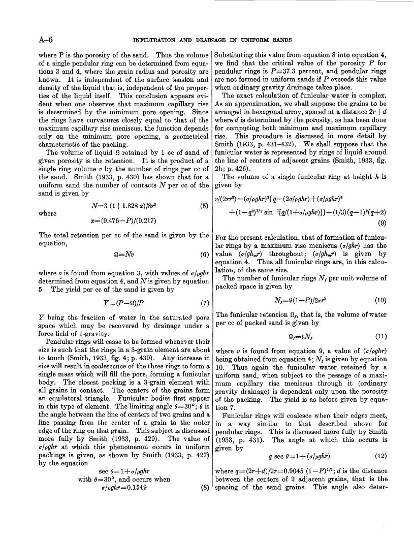
It is not difficult to compute the initial yield of a cylindrical column of uniform sand such as shown in figure 6-4, when drained by a field of 1-gravity. The
Funiculor woter yield
No yield
A
ooo
4
o
oo, ooo
Im
Jm
FIGURE 6. Drainage relations of a cylindrical column of sand: A, Yield regions of a Vertical column; B, Eolations for an inclined column.
initial yield is that which results when the maximum rise meniscus has traveled down the sand column from its initial position at the top to its final position in the column. This is the yield which results from the passage of a maximum capillary rise meniscus over the sand, and does not include the additional water that will drain from the sand because of thermo- dynamic adjustments as final equilibrium is approached.
For a uniform sand there are two cases in the initial- yield problem. If P<37.3 percent, the retained water consists of pendular water RP and bulk capillary water RTO . If P>37.3 percent, the retained water consists of funicular Rf and bulk capillary water Rm . Let H be the height of the column whose cross section is A. Suppose P>37.3 percent, then the water is funicular from the top of the column for a distance hf (H hm). Below it is bulk-capillary water for a distance hm. The volume of packing containing funicular water is (H ht^A- that for bulk water is hmA. The yield of funicular water, per unit volume of the column, is given by equation 7 with a value of fi being given by equation 11. There is no yield from bulk-capillary water since it is completely retained. The specific yield that is the water drained from unit volume of the formation, or column in this case is the total yield divided by the total volume V of the rock drained. Thus the specific yield S of the column in figure 6-4 is
S=P(l-Qf/P)(l-hJH) (14)
and similarly for pendular water, Qf is replaced by flp computed from equation 6. The specific retention R for P>37.3 percent is
R=P{(Q,/P) + (hJH) (l-Qf/P\} (15)
and similarly for pendular-water.As occurs where calculating the final equilibrium, if
the yield is from both the pendular and funicular zones, it is not difficult to write the additional terms in equa tions 14 and 15. The schematic diagram of figure 6-4 then would include three zones of length hP, hf} and hm .
If the column is inclined, it can easily be seen from figure QB that the values given by equations 14 and 15 are still valid if, instead of the vertical distance hm and H, we use values lm and L measured along the axis of the column. From figure 6B it can easily be seenthat j==J*.
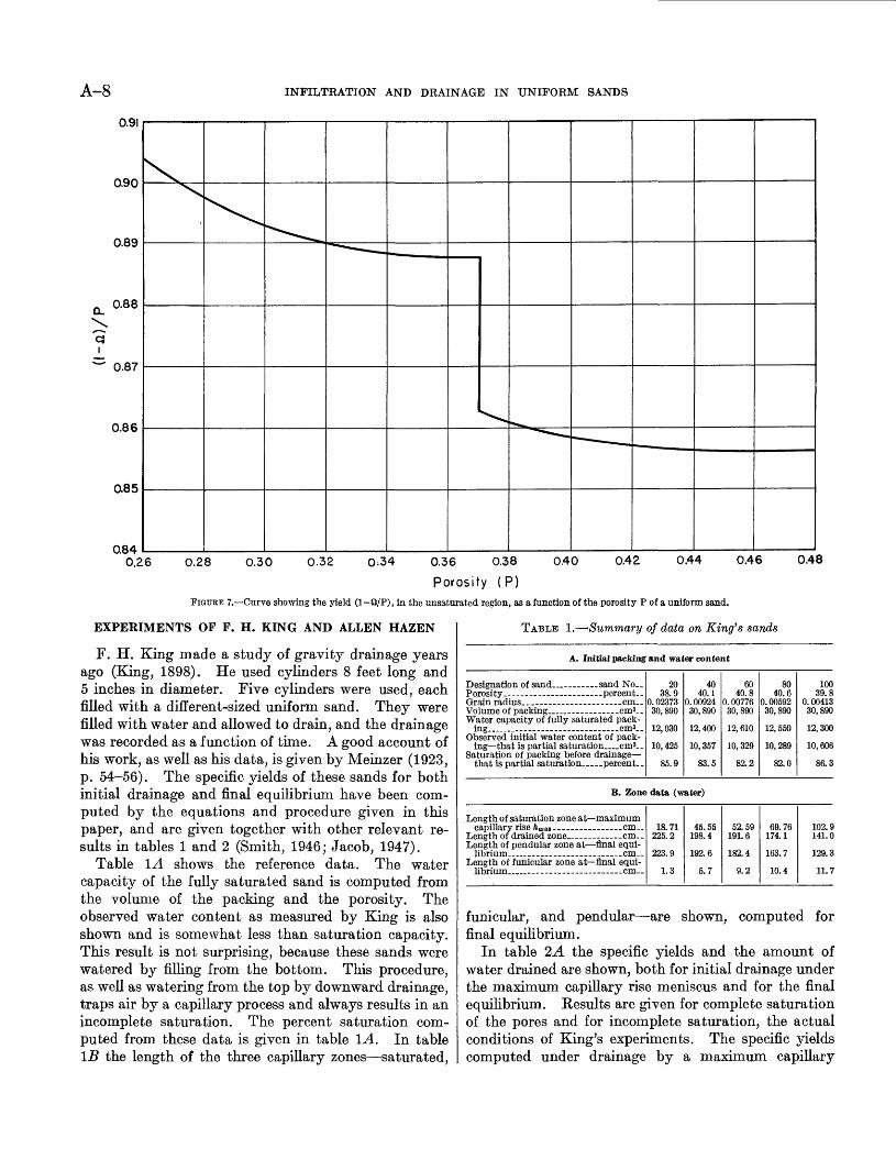
For convenience of calculation the values of (1 n)/P have been plotted as a function of P and are shown in the curve of figure 7. In the region 26 percent<P<37.3 percent, retained water is considered to be pendular (computed from equation 6); and for 37.3 percent<P<48 percent, it is considered funicular and computed from equation 11.
A-8 INFILTRATION AND DRAINAGE IN UNIFORM SANDS
Cj I
0.91
0.90
0.89
0.88
0.87
0.86
0.85
Q840.26 0.28 0.30 0.32 0;34 0.36 0.38 0.40 0.42 0.44 0.46 0.48
Porosity (P)FIGURE 7. Curve showing the yield (1 Q/P), in the unsaturated region, as a function of the porosity P of a uniform sand.
EXPERIMENTS OF F. H. KING AND ALLEN HAZEN
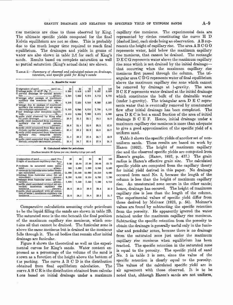
F. H. King made a study of gravity drainage years ago (King, 1898). He used cylinders 8 feet long and 5 inches in diameter. Five cylinders were used, each filled with a different-sized uniform sand. They were filled with water and allowed to drain, and the drainage was recorded as a function of time. A good account of his work, as well as his data, is given by Meinzer (1923, p. 54-56). The specific yields of these sands for both initial drainage and final equilibrium have been com puted by the equations and procedure given in this paper, and are given together with other relevant re sults in tables 1 and 2 (Smith, 1946; Jacob, 1947).
Table IA shows the reference data. The water capacity of the fully saturated sand is computed from the volume of the packing and the porosity. The observed water content as measured by King is also shown and is somewhat less than saturation capacity. This result is not surprising, because these sands were watered by filling from the bottom. This procedure, as well as watering from the top by downward drainage, traps air by a capillary process and always results in an incomplete saturation. The percent saturation com puted from these data is given in table L4. In table IB the length of the three capillary zones saturated,
TABLE 1. Summary of data on King's sands
A. Initial packing and water content
Porosity __ - percent-
Volume of packing __ cm^-. Water capacity of fully saturated pack-
Observed initial water content of pack ing that is partial saturation _ cms..
Saturation of packing before drainage that is partial saturation. percent..
20 38.9
0. 02373 30, 890
12,030
10,425
85.9
40 40.1
0. 00924 30,890
12,400
10,357
83.5
60 40.8
0. 00776 30,890
12, 610
10, 329
82.2
80 40.6
0. 00592 30,890
12,550
10,289
82.0
100 39.8
0. 00413 30,890
12,300
10,606
86.3
B. Zone data (water)
Length of saturation zone at maximum capillary rise hm&i--- ------------- cm..
Length of drained zone. cm- Length of pendular zone at final equi-
Length of funicular zone at final equi-
18.71 225.2
223.9
1.3
45.55 198.4
192.6
5.7
52.59 191.6
182.4
9.2
69.76 174.1
163.7
10.4
102.9 141.0
129.3
11.7
funicular, and pendular are shown, computed for final equilibrium.
In table 2A the specific yields and the amount of water drained are shown, both for initial drainage under the maximum capillary rise meniscus and for the final equilibrium. Results are given for complete saturation of the pores and for incomplete saturation, the actual conditions of King's experiments. The specific yields computed under drainage by a maximum capillary
GRAVITY DRAINAGE AND RELATION TO SPECIFIED YIELD OF UNIFORM SANDS A-9
rise meniscus are close to those observed by King. The ultimate specific yields computed for the final Kelvin equilibrium are not so close. This is probably due to the much longer time required to reach final equilibrium. The drainages and yields in grams of \\ater are also shown in table 2A for each of King's ssinds. Results based on complete saturation as well as partial saturation (King's actual data) are shown.
TABLE 2. Summary of observed and calculated values on drainage, retention, and specific yield for King's sands
A. Results for water
O ^served drainage at partial satura- iion_._ ___ ... .grams-.
D rainage after passage of maximum japillary rise meniscus (air correc-
D-ainage due to passage of maximum 3apillary rise meniscus (no air correc-
Final drainage after complete equilib-
Sj eciflc yield observed by King after
Specific yield computed from maximum 3apillary rise at partial satura-
Sj 'eciflc yield computed from final equi- ibrium; partial saturation.. .percent
Sj eciflc yield computed from maximum ;apillary rise; complete satura- ;ion _ ... ___ --.. _ .-percent.-
Sj eciflc yield computed from final equi- ibrium; complete saturation.percent.-
20 0.860
8,304
8,200
9,560
9,410
26.9
26.6
30.4
31.0
35.4
40 0.858
7,882
7,250
8,680
8,988
25.5
23.4
29.2
28.2
34.7
60 0.857
6,814
6,950
8,510
7,800
22.1
22.6
25.2
27.6
31.0
80 0.857
5,713
6,280
7,700
6,972
18.5
20.2
22.6
24.7
27.8
100 0.859
4,775
6,250
6,110
6,669
16.5
17.0
18.7
19.8
21.6
B. Calculated values for petroleum[Surface tension 30 dynes per cm; density 0.8 gr per cm8]
Height of maximum capilliary rise: ftma* cm--
Piitroleum in saturated zone; calcu- lated.. ____ . ____ ___ grams--
PI itroleum in funicular zone before drain-
Drainage from funicular zone; (no air
Drainage from funicular zone; (air cor rection).... _.. grams..
Specific yield calculated without air cor rection; maximum capillary rise meniscus __ percent-
Si lecific yield calculated with air correc tion of table 1; maximum capillary rise meniscus ___ percent..
20
9.80
950
11,080
9,290
7,870
30.8
25.8
40
23.64
1,860
10,540
9,050
7,550
29.3
24.5
60
27.90
1,930
10,680
9,150
7,520
29.6
24.4
80
36.06
2,340
10, 210
8,750
7,180
28.4
23.3
100
53.70
3,220
9,080
7,790
6,710
25.2
21.7
Comparative calculations assuming crude petroleum to be the liquid filling the sands are shown in table 2B. The saturated zone is the one beneath the final position of the maximum capillary rise meniscus, which con tains oil that cannot be drained. The funicular zone is above the same meniscus but is drained as the meniscus falls through it. The oil bodies that remain after initial drainage are funicular.
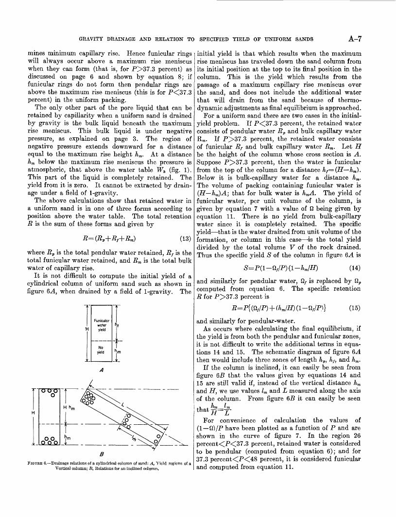
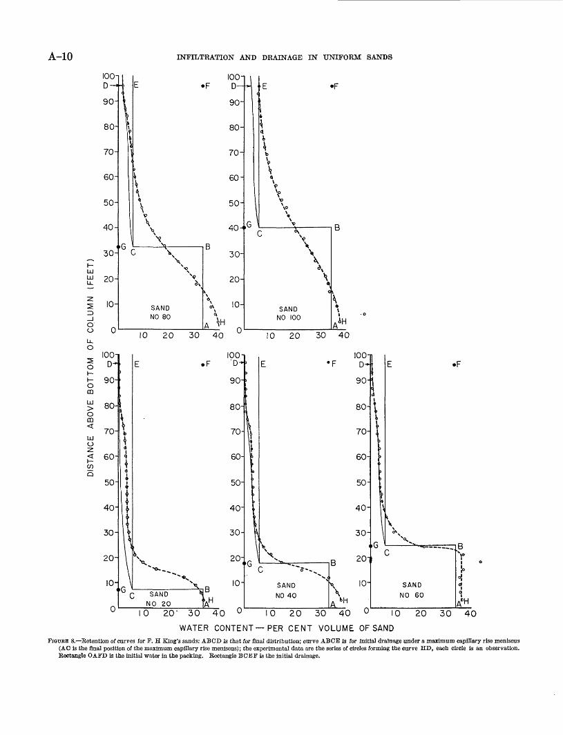
Figure 8 shows the theoretical as well as the experi mental curves for King's sands. Water content ex pressed as a percentage of the volume of the sand is aiown as a function of the height above the bottom of tie packing. The curve A B C D is the distribution obtained from final equilibrium calculation. The curve A B C E is the distribution obtained from calcula- tions based on initial drainage under a maximum
capillary rise meniscus. The experimental data are represented by circles constituting the curve H D (dashed line), each circle being an observation. A B rep resents the height of capillary rise. The area A B C G O represents water, held below the maximum capillary rise meniscus, that cannot be drained. The rectangle D E C G represents water above the maximum capillary rise zone which is not drained by the initial drainage that occurring when the maximum capillary rise meniscus first passed through the column. The tri angular area C D G represents water of final equilibrium above the maximum capillary rise zone which cannot be removed by drainage at 1-gravity. The area B C E F represents water drained at the initial drainage which constitutes the bulk of the drainable water (under 1-gravity). The triangular area DEC repre sents water that is eventually removed by unsaturated flow after initial drainage has been completed. The area D E C is but a small fraction of the area of initial drainage B C E F. Hence, initial drainage under a maximum capillary rise meniscus is more than adequate to give a good approximation of the specific yield of a uniform sand.
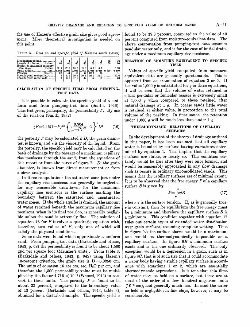
Table 3 shows the specific yields of another set of non- uniform sands. These results are based on work by Hazen (1892). The height of maximum capillary rise and the observed specific yields are computed from Hazen's graphs. (Hazen, 1892, p. 437.) The grain radius is Hazen's effective grain size. The calculated specific yields are computed from the capillary theory for initial yield derived in this paper. No drainage occured from sand No. 5, because the length of the column is less than the height of maximum capillary rise. An unsaturated zone occurs in the other sands; hence, drainage has occured. The height of maximum capillary rise is less than the length of the column. The experimental values of specific yield differ from those derived by Meinzer (1923, p. 54). Meinzer's values are found by subtracting the specific retention from the porosity. He apparently ignored the water retained under the maximum capillary rise meniscus. Subtracting the specific retention from the porosity to obtain the drainage is generally useful only in the funic ular and pendular zones, because there is no drainage from the saturated zone just under the maximum capillary rise meniscus when equilibrium has been reached. The specific retention in the saturated zone is equal to the porosity. The specific yield of sand No. 5 in table 3 is zero, since the value of the specific retention is clearly equal to the porosity. The values of the calculated specific yield are in air agreement with those observed. It is to be noted that, although Hazen's sands are not uniform,
A-10 INFILTRATION AND DRAINAGE IN UNIFORM SANDS
»F
10 20 30 40 10 20 30 40
s oh-h-oCD
>O CD<
UJO2
£0)Q
lOO-iD*
90-
80-
70-
60-
50-
40-
30-
20-
10-i
r>
>
;
\
bi
<J
4 *<j
I iUU
11\\
G c
E .F
i
V^"""V
; SAND ^
NO 20 'AH
70-
SAND
NO 40X
100-j D-*
90-
80-
70-
60-
50-
40-
30-
i20-
io-
i
i1t
1
ii\
' W
E .F
K *--SK_ i Dc ?,
1
SAND «|
NO 60 1
0 20- 30 40 10 20 30 40 10 20 30 40
WATER CONTENT PER CENT VOLUME OF SANDFKTOBE 8. Retention of curves for F. H King's sands: ABCD is that for final distribution; curve ABCE is for initial drainage under a maximum capillary rise meniscus
(AC is the final position of the maximum capillary rise meniscus); the experimental data are the series of circles forming the curve HD, each circle is an observation. Rectangle OAFD is the initial water in the packing. Rectangle BCEF is the initial drainage.
GRAVITY DRAINAGE AND RELATION TO SPECIFIED YIELD OF UNIFORM SANDS A-ll
the use of Hazen's effective grain size gives good agree ment. More theoretical investigation is needed on this point.
TABLE 3. Data on and specific yield of Hazen's sands (water)
Length of column __ inches- Height of maximum capillary
560
99.90.002
3600
460
47.00.003
448.26.0
260
25.60.006
4220.317.2
960
9.00.017
4230.6
32
660
6.70.03532.526.0
22
160
3.50.048
4032.3
31
5a60
0.140
1660
0.280.500
4437.6
36
CALCULATION OF SPECIFIC YIELD FROM PUMPING- TEST DATA
It is possible to calculate the specific yield of a uni form sand from pumping-test data (Smith, 1946). This test gives, principally, the permeability F. By use of the relation (Smith, 1932)
the porosity P may be calculated if D, the grain diame ter, is known, and r? is the viscosity of the liquid. From the porosity, the specific yield may be calculated on the basis of drainage by the passage of a maximum capillary rise meniscus through the sand, from the equations of this report or from the curve of figure 7. D, the grain diameter, is known from direct measurement or from a sieve analysis.
In these computations the saturated zone just under the capillary rise meniscus can generally be neglected for any reasonable drawdown, for the maximum capillary rise meniscus is the surface marking the boundary between the saturated and unsaturated water zones. If the whole aquifer is drained, the amount of water retained beneath the maximum capillary rise meniscus, when in its final position, is generally negligi ble unless the sand is extremely fine. The solution of equation 16 for P involves a quadratic equation with, therefore, two values of P, only one of which will satisfy the physical conditions.
Some data were found which approximate a uniform sand. From pumping-test data (Barksdale and others, 1943, p. 68) the permeability is found to be about 1,500 gpd per square foot (Meinzer's units). From table 3, (Barksdale and others, 1943, p. 942) using Hazen's 10-percent criterion, the grain size is D=0.0250 cm. The units of equation 16 are cm, sec, H2O per cm, and therefore the 1,500 permeability value must be multi plied by the factor 4.716 X 10~5 (Wenzel, 1942) to con vert to these units. The porosity P is found to be about 33 percent, compared to the laboratory value of 43 percent (Barksdale and others, 1943, table 3), obtained for a disturbed sample. The specific yield is
found to be 39.3 percent, compared to the value of 40 percent computed from moisture-equivalent data. The above computation from pumping-test data assumes pendular water only, and is for the case of initial drain age under a maximum capillary rise meniscus.
RELATION OF MOISTURE EQUIVALENT TO SPECIFICYIELD
Values of specific yield computed from moisture- equivalent data are generally questionable. This is apparent from an examination of equation 3 or 9. If the value 1,000 g is substituted for g in these equations, it will be seen that the volume of water retained in either pendular or funicular masses is extremely small at 1,000 g when compared to those retained after natural drainage at 1 g. In coarse sands little water is retained at either value, in proportion to the total volume of the packing. In finer sands, the retention under 1,000 g will be much less than under 1 g.
THERMODYNAMIC RELATIONS OF CAPILLARY SURFACES
In the development of the theory of drainage outlined in this paper, it has been assumed that all capillary water is bounded by surfaces having curvatures deter mined by equation 1. This implies that the capillary surfaces are stable, or nearly so. This condition cer tainly would be true after they were once formed, and would be reasonably approached in any slow drainage such as occurs in ordinary unconsolidated sands. This means that the capillary surfaces are of minimal extent. It is to be observed that the free energy F of a capillary surface S is given by
(17)
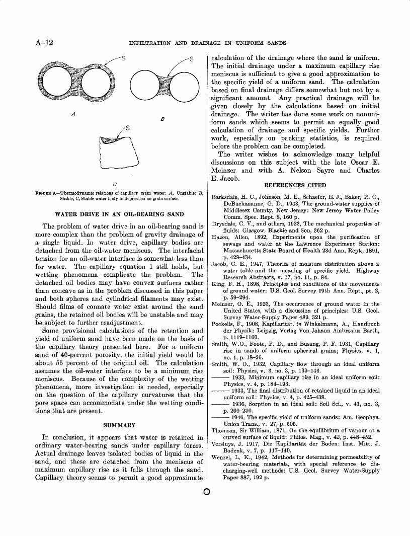
where a is the surface tension. If, as is generally true, a is constant, then for equilibrium the free energy must be a minimum and therefore the capillary surface S is a minimum. This condition together with equation 17 rules out certain types of extended water distribution over gram surfaces, assuming complete wetting. Thus in figure 9-4 the surface shown would be a maximum, and would be thermodynamically impossible as a capillary surface. In figure QB a minimum surface exists and is the one ordinarily observed. The only exception would be a depression in a grain, such as in figure 9(7, that is of such size that it could accommodate a water body having a stable capillary surface in accord ance with equations 1 or 2, which are essentially thermodynamic expressions. It is true that thin films of water may be held on a surface, but these are at most of the order of a few hundred angstrom units (10~8 cm), and generally much less. In sand the water so held is negligible; in fine clays, however, it may be considerable.
A-12 INFILTRATION AND DRAINAGE IN UNIFORM SANDS
FlQPBE 9. Thermodynamic relations of capillary grain water: A, Unstable; B, Stable; C, Stable water body in depression on grain surface.
WATER DRIVE IN AN OIL-BEARING SAND
The problem of water drive in an oil-bearing sand is more complex than the problem of gravity drainage of a single liquid. In water drive, capillary bodies are detached from the oil-water meniscus. The interfacial tension for an oil-water interface is somewhat less than for water. The capillary equation 1 still holds, but wetting phenomena complicate the problem. The detached oil bodies may have convex surfaces rather than concave as in the problem discussed in this paper and both spheres and cylindrical filaments may exist. Should films of connate water exist around the sand grams, the retained oil bodies will be unstable and may be subject to further readjustment.
Some provisional calculations of the retention and yield of uniform sand have been made on the basis of the capillary theory presented here. For a uniform sand of 40-percent porosity, the initial yield would be about 55 percent of the original oil. The calculation assumes the oil-water interface to be a minimum rise meniscus. Because of the complexity of the wetting phenomena, more investigation is needed, especially on the question of the capillary curvatures that the pore space can accommodate under the wetting condi tions that are present.
SUMMARY
In conclusion, it appears that water is retained in ordinary water-bearing sands under capillary forces. Actual drainage leaves isolated bodies of liquid in the sand, and these are detached from the meniscus of maximum capillary rise as it falls through the sand. Capillary theory seems to permit a good approximate
calculation of the drainage where the sand is uniform. The initial drainage under a maximum capillary rise meniscus is sufficient to give a good approximation to the specific yield of a uniform sand. The calculation based on final drainage differs somewhat but not by a significant amount. Any practical drainage will be given closely by the calculations based on initial drainage. The writer has done some work on nonuni- form sands which seems to permit an equally good calculation of drainage and specific yields. Further work, especially on packing statistics, is required before the problem can be completed.
The writer wishes to acknowledge many helpful discussions on this subject with the late Oscar E. Meinzer and with A. Nelson Sayre and Charles E. Jacob.
REFERENCES CITED
Barksdale, H. C., Johnson, M. E., Schaefer, E. J., Baker, R. C.,DeBuchananne, G. D., 1943, The ground-water supplies ofMiddlesex County, New Jersey: New Jersey Water PolicyComm. Spec. Rept. 8, 160 p.
Drysdale, C. V., and others, 1923, The mechanical properties offluids: Glasgow, Blackie and Son, 362 p.
Hazen, Alien, 1892, Experiments upon the purification ofsewage and water at the Lawrence Experiment Station:Massachusetts State Board of Health 23d Ann. Rept., 1891,p. 428-434.
Jacob, C. E., 1947, Theories of moisture distribution above awater table and the meaning of specific yield. HighwayResearch Abstracts, v. 17, no. 11, p. 84.
King, F. H., 1898, Principles and conditions of the movementsof ground water: U.S. Geol. Survey 19th Ann. Rept., pt. 2,p. 59-294.
Meinzer, O. E., 1923, The occurrence of ground water in theUnited States, with a discussion of principles: U.S. Geol.Survey Water-Supply Paper 489, 321 p.
Pockells, F., 1908, Kapillaritat, in Winkelmann, A., Handbuchder Physik: Leipzig, Verlag Von Johann Ambrosius Barth,p. 1119-1160.
Smith, W.O., Foote, P. D., and Busang, P. F. 1931, Capillaryrise in sands of uniform spherical grains; Physics, v. 1,no. 1, p. 18-26.
Smith, W. 0., 1932, Capillary flow through an ideal uniformsoil: Physics, v. 3, no. 3, p. 139-146.
1933, Minimum capillary rise in an ideal uniform soil: Physics, v. 4, p. 184-193.
1933, The final distribution of retained liquid in an ideal uniform soil: Physics, v. 4, p. 425-438.
1936, Sorption in an ideal soil: Soil Sci., v. 41, no. 3, p. 209-230.
1946, The specific yield of uniform sands: Am. Geophys.Union Trans., v. 27, p. 605.
Thomson, Sir William, 1871, On the equilibrium of vapour at a curved surface of liquid: Philos. Mag., v. 42, p. 448-452.
Versluys, J. 1917, Die Kapillaritat der Boden: Inst. Mitt. J. Bodenk, v. 7, p. 117-140.
Wenzel, L. K., 1942, Methods for determining permeability of water-bearing materials, with special reference to dis charging-well methods: U.S. Geol. Survey Water-Supply Paper 887, 192 p.
O