Embed Size (px)
Citation preview
, '"
I~,t
'f
,~"
I'I
j. j,11
>i 1I
'I.
'1
j
1 J
-
HANDBOOKOF
,
-~.~'"I--- -
~PUBLICATION No. 715F.
PRICE, ONE SHILLING
THB
AUSTIN MOTOR Co. LTD.LONGBRIDGE:: BIRMINGHAM
"
[ J-I
1=
"I1
I I
jI jI '
11 J I11
j I'11,
II
II
JJ '.
I"I
--~ - -------.--.
HANDBOOKOF
. ..,
~)VPRICE - ONE SHILLING
nnd EDITION.
THE AUSTIN MOTOR CO. LTD.LONGBRIDGE ~ BIRMINGHAMT,zephones CENTRAL 4140-3. PRIORY 2101-2116Telegram.<.- "SPEEDILY, NORTHFIELD." . Code.- BENTLEY'S
LONDON SHOWROOMS & REPAIR DEP6T FOR 7 & 10 H.P.:
479-483, Oxford Street, W.ITelePhone'
MAYFAIR7620 to 7639.T,ze<rams .'
"AUSTINETTE, WESDO, LONDON."
AND
HOLLAND PARK HALLHOLLAND PARK AVENUE. W.l1
I
l."f",n,""Ih"'oo' 71S Fpua" q~" 'he numb"
\ ..
-,
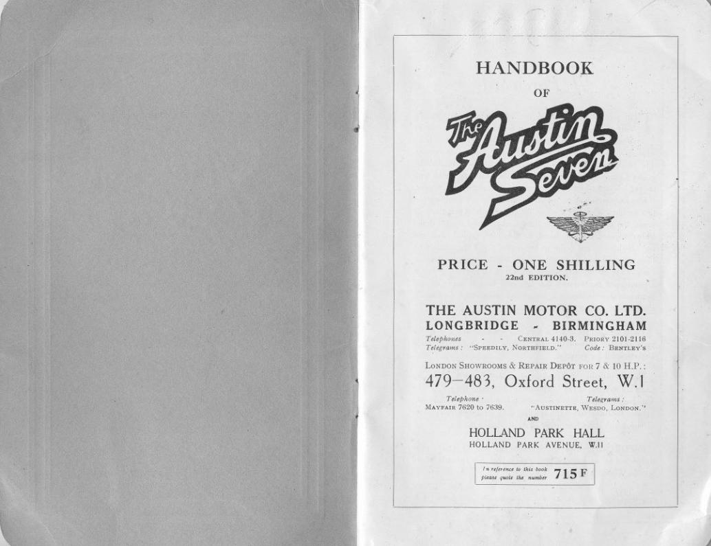
CONTENTS
Many of the adjustments and attentions described in the following
pages are included in the" Schedule of Charges for Repairs." The
Company is confident that owners will find it to their own benefit
to make the fullest use of this standard price repair and maintenance
service. which it is a function of all Austin dealers to offer.
I~
FANFRONT AXLE.Lubricationof ..FUSE.Adionof th, . .GEARBOX. Lubrication ofGREASE GUN. How to u" th,HUBS (Front ond Roar) Luhrication ofIGNITION. Timin,
.. Sy,t,m. Tb,INFLATING SEAT INTERfORSLAMPS. Ca" of ..LUBRICATION CHARTLUBRICANTS. Choi" ofREAR AXLE. Lubricatiou ofROAD SPRINGS. LubricacionofRUNNING ADJUSTMENTSSHOCK ABSORBERS.Adiu,tm,nt of . .SPORTS ENGINE. Moint,uonce In,truetio",STEERING. Ad;u,tm,nt of ..STEERING GEAR. Lubrication ofTOOLS. SuppliodTYRES.Tb, ..UNIVERSAL JOINT. Lubricatiou ofVALVE TAPPETS. Adiu,tm,nt of
WHEEL.Ch.ngiu, . . .WIRING.IIIn.t"cionof
..
PAG'36111112123751
42.4528
44.4596
7.814.18
14161727
40.412335
35.3925.27
729.48
293727243021
19.22503431252829
40.48 .47
32.3346.47
28531828401039
THE information contained in this Handbook is intended
only to guide and assist owners or drivers of Austin cars to
preserve the car in its proper satisfactory running condition.
This publication must not be considered as a complete manual.The handbook does not in any manner vary or extend the liability
0 the Company. which is limited to the Warranty issued with
the car. Where no information i. given for a particular adjustment.
it may be regarded as one which the average owner would entrust
to a garage. When the occasion for adjustments of this character
arises. the owner should seek the aid of the local Austin dealer
whose address will be found in the list supplied with the
car. Both owner and dealer are encouraged to call upon the Service
Department of the Company for advice. whether upon the manage-
ment of the car. the effecting of adjustment. or methods of repair.
Cfwners need not suppose that they will have to apply all the
attentions given in this book. but careful notice should be taken of
the chapters dealing with maintenance.
i
AMMETER READINGSATTENTIONS. Daily
W"klyMonthly
" O"..ionolBATTERY. Tb,BODYWORK. Ca" ofBRAKES.Ad;u,ti., th, . .
BRAKE GEAR. Lubrication of ..BRAKES. R,.liningCAR. Control of th,
.. Foatu<" o!th, ..
.. Tb,N,wCARBURETTER. Tb,
.. Ad;u,tm,nt of
.. Slow Runnin, Device.. .. Looko" born
CLUTCH. Lubri"cion of M"h.ni,mCOMBUSTION CHAMBER. Cloanin,COOLING SYSTEMDYNAMO. Th,ELECTRICAL EQUIPMENT. Tb,ENGfNE. Lub,ication of
St.rtingtb,
fi Foreword.
Two additional publications give lists and illustrations of all the
parts, and their prices, respectively. and the owner should find these
books helpful for reference.
IMPORTANT.-See special note at end of book, withreference to accessories and equipment not mannfacturedby the Austin Motor Co., Ltd.
June. 1932.
2 3
\ ,

----..
Th, Au,,1n Smu Tuum.
The AUSTIN SEVEN
THE Austin Seven is acknowledged to be the best small car inthe world.
It is designed for, and will carry in comfort, four adults upto a weight of 40 stones.
There are six models made, the Tourer, the Metal Saloon, thede luxe Saloon, the Two-Seater, and two Sports Models (one super-charged). The Tourer, with its easily operated hood, and side curtainsthat open with the doors, provides complete protection in even themost inclement weather. The closed models are alike in general linesand equipment. Particularly good features are the wide doorswith one-piece windows, which are mechanically raised or lowered.The large single panel windscreen, that can be opened wide, andsecured by an ingenious lever fastening, easily reached from thedriver's seat, is another advantage. Their names accuratelydescribe the two-seater and sports models.
Except on the two-seater and sports models, both front seats tiltforward and "allow ready access to the rear seats or luggage space.
It has a 4-cylinder, water-cooled engine, three-speed gear-box,and bevel drive through the differential. Lubrication is by pump,and cooling is on the thermo-syphon system and by fan.
The complete equipment includes electric hand starting andlighting switches, air strangler, electric horn, speedometer, auto-matic windscreen wiper, license holder, shock absorbers, sparewheel and tyre and blank number plates. All fittings are chromiumplated.
4
"
The hand lever and pedal each apply brakes to all four wheelswhich carry 3.50-19 Dunlop balloon tyres.
The Austin Seven is particularly suitable for the woman driver.It requires little physical effort to drive and control, and for that'reason its use enables her to do shopping calls without fatigue, visither friends, attend social and other functions, or make excursionsor trips in any direction in any weather. For the same reasonsbusiness men find it an excellent vehicle, and commercial travellersand others whose occupation compels frequent calls over an extendedarea, have in the little car an embodiment of all they require. Callscan be made in places where trains, trams and 'buses are infrequent.
In large establishments where the instant use of a car is of vitalimportance in cases of emergency, such as sudden illness or accident,the Seven has been installed as a "tender," and in addition to itssuperiority over large unweildly cars for short runs, has proved areal time and money saver.
As 45 to 50 miles per gallon is the average petrol consumption, thecost of transit is below the cost of fares on any public conveyance, andin this particular the Austin Seven has no rival. "
II
Its speed, economy, reliability and road-holding qualities havebeen admitted beyond dispute.
Thousands of motorists have had their first experiences on a"Seven," thousands more will follow them.
Having successfully passed through a decade of severe use and trial,it has emerged a really successful and popular favourite; and itssplendid qualities are internationally recognized.
j
~
Th, A~Hu Smu Salouu.
5
. ..,lIipti, <co", 'p,ing in f,ont.Qn"t"dhpti".t "".Sho,k.b,o,b", '" fitt,d to fmnt .nd "".
STEERfNG . Wo,m.nd wb,.!. b"ing p,ovi,ionfo, t.king up w""
FRONT AXLE . Fo,god. I ",tion.
BRAKES . On .11fou, wb,d, , ",ily .diu,tabl,. Bothh.nd .nd footb"k" o"",t, on .11fou, wh"j"
-
DIMENSIONS
ENGINE
STARTER.
CLUTCH.
GEARBOX.
REAR AXLE .
SPRINGS
WHEELS.
CONTROLS .
PETROL TANK
LICHTING
BODYWORK
,ITSLEADINGFEATURES
The NEW CARFull '" I,ngth,9 ft. 6 in. (2.8%mm.); Full '" width(ov" doo, h.ndI,,) 4 ft. 2in. (1.270mm.); Wh,dh.." 6 ft3 in. (1,905 mm.); Wh,dh..,. D, Lux< Modd 6ft. 9in(2057 mm.); T"d, 3 ft. 4 in. (1,016 mm.); W,ight,'pp'OX. 8. cwt. (425 kg.) Gmund d",.n" 8j in. (220 mm.).
. Fom.,ylind", w"".,ool,d, d,t"h.bI, h"d.80", 2.2in. (56mm.)f7475 R A C t
.7
S k 3.
(76 ). "'.. . . ." mg.tm" m. mm.
B"k, hon,.pow", 10.5.t 2,400'"Ignition, Coi!.Oil ,i«ul.tion' hy pump.Cooling' Th"mMyphon with film "di.to, .nd f.n.Roll" ",nk,h.ft b",ing'.
I
I
I
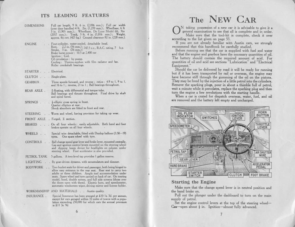
ON taking possession of a new car it is advisable to give it ageneral examination to see that all is complete and in order.
Make sure that the tool-kit is complete, check it overaccording to the list given on page 53,
If you are not already familiar with Austin cars, we stronglyrecommend that this handbook be carefttlly studied,
Before running see that the car is sttpplied with fuel and waterand that the engine and gearbox have the necessary quantities of oil.The battery should contain the required amount of acid. Forquantities of oil and acid see sections "Lubrication" and "ElectricalEquipment. "
Should the car be delivered by road it will be ready for runningbut if it has been transported by rail or overseas, the engine mayhave become stiff through the gumming of the oil on the pistons.They may be freed by the injection of a little petrol into the cylinders.Remove the sparking plugs, pour in about a thimble full of petrol,wait a minute while it percolates, replace the sparking plug and thenturn the engine a few revolutions with the starting handle,
When a car is crated for dispatch overseas, water, fuel, and oilare removed and the battery left empty and uncharged.
h.p.
. EI""i,,!.
Singl,.pI.t,.
Th", ,p"d, fo<w"d, .nd ""n,; "tio" 4.9 to I. 9 to I,.nd 16to I ; 'm"', 21 to I ; B.1Ib",ing, thmu.hout.
! .flo.ting, with diff",nti.1 .nd tO'qu, tub,.B.1Ib",ing, .nd thm," thmughout. Fin.I do" by .h.ft.nd 'pi"I bm!.
Sp"i.1 wi" d""h.bI" fitt,d with DunIop b.lIoon (3.50--19)ty"'. On, ,p," wh"J with ty".
. B.1I,h.ng, ,p"d g'" Im, .nd b"k, Im', mount,d"n',alIy.G.. .nd ignition<on"oll"", mount,don the ,twing wh,,1.nd dipping b"m d"i" fa<h"dlight, on <oIumnund",twing wh,,!. Foot",01"'10< i, .bo pmvid,d.
5 g.lIon'. A two.lmI t.p pMid" I g.lIon"""".
By g",.d,i"n dyn.mo, with ","mul.ton .nd dimm".
Two bu,k,t ".t, fo, d,iv" .nd p'",ng", both b,ing hing,d to.lIow "'y ,n".n" to th, "" "... R", ",t to wry two.duI" °' th", ,hild"n. AmpI, tool ",ommodation und"".t,. Sp'" wh"I .nd tY" wri,d on b"k of ea" On touringmod,I. hood, doubI, "",n, .nd full ,id, "",n, (tho" ov"th, doo" open with th,m). EI",o, hom, .nd ,""dom't",.utom..i, wind"",n wip", d,iving miITo, .nd Ii"n" hold",
i STARTERSWITCH
Starting the EngineMake sure that the change speed lever is in neutral position and
the hand brake on.Pull out the plunger under the dashboard to turn on the main
supply of petrol.Set the engine control levers at the top of the steering wheel-
c..s-open about t in. Ignition-almost fully advanced.
WORKMANSHIP AND MATERIALS. Au,tin qu.Iity.
INSURANCE. Sp"i.I In,""n" h.. b"n ".ng,d.t £10 J,. 3d. p" .nnum,,mpt fa<"" ,"'god within I0 mile. 01town' with. popu.l.tion "",ding 250,000 fa< whi,h m, th, .nnu.1 p"miumi. £11 3" 9d
!\
67
J

rGive the engine a few turns with
the starting handle to make sure thatthe crankshaft is free (pushing thehandle in to engage fully with thestarting nut, before turning it), thenswitch on, turning the left-hand switchto "Summer i Charge" or "WinterFull c." Pull out the wire on theinstrument board to close the car-buretter air inlet, and again give thecrankshaft a few sharp turns bymeans of the starting handle, making sure to pull the handle upwardsto commencewith; or firmly press the starter switch. Be sure torelease the air shutter wire afler the engine has slarted. Do not tryto start the engine when cold by the electric starter, nor allow theengine to race when first starting up, as time must be allowed forthe oil to circulate and lubricate various bearings.
When the engine is running, see that the starting handle is nothanging down. It should be replaced in a horizontal position, Thereis a catch which will secure it in its proper place there on the off-sideof the car,
Never leave the ignition switch on for any lengthy period whilethe engine is not running. The warning lamp on the switch boardwill remind you of this.
Difficulty in StartingDifficulty in starting may be caused either through sucking too
much petrol into the cylinders, or too little. When starting with thethrottle all but closed, a strong suction takes effect on the pilot jet,and it may not be necessary to flood \he carburetter; in any case itshould only be flooded slightly. If petrol is passing through the car-buretter the suction can generally be heard. If the engine fails to startand there is a good deal of petrol overflowing from the carburetter itis almost certain that the mixture getting into the cylinder is too rich.The throttle should then be opened half-way to reduce the suction.On firing. the engine will race away, and the throttle should be almostclosed. If the engine does not fire close the throttle entirely, and tryagain, After a stop in hot weather, failure of the engine to start is morelikely to be due to a too rich mixture than one too lean, and one shouldstop the engine by the switch only after quite closing the throttle.Re-start the engine with the throttle closed.
If after the foregoing measures have been carried out the enginefails to start. the reason will probably be due to faulty ignition orcarburation.
IGNITION: First examine the wires and see that the sparkingplugs are connected. Then test the gap of the plug points by meansof the thick end of the gauge provided in the tool kit. If the pointsare dirty, clean them before replacing the plug.
CARBURATION: The slow running jet may be stopped upor a main jet choked, Blow them out with a tyre pump.
The engine should never be allowed to run at high speedsfor the first 300 miles.
II
I
8
.L-~
I
I
~
.~
'1,
i
- ,CONTROL OF THE CARSettin~ of Control Levers
AFTER having started the engine, see that the starter handleis in a horizontal position, if it is left hanging down it permitswet and damp to work into the bearing of the starter handle shaft
and causes rust. Keep the ignition lever in the advanced position;should the engine commence to "rumble" or run roughly, retardthe lever, but advance it again as soon as the load on the engineis lessened. The "gas" lever should be set generally for slow run-ning and the speed of the car controlled by the accelerator pedal.Changing Gear
Double declutching will be found the best method of gear changingon the Austin Seven and should be adopted straight awar. Alsowhen changing up from first to second or second to third gear, thefoot should be taken off the accelerator pedal, and when changingfrom top to second or from second to first, it'should be held down.The car should be well accelerated on each speed when changing up,and a deliberate pause should be made with the gear lever in neutralposition and with the clutch in whether changing up or down,
Always change gear early on a hill; never allow the engine tolabour in any gear and expect it to pick up speed on changing into
a lower one when the car haanearly stopped. Do not persistin attempting to drive the caruphill in top gear when thespeed falls below 18 m.p.h.-change down to second. If thecar has been drawn back by thereverse gear, wait until it isstationary before engaging aforward speed. Do not engagethe reverse gear when the car istravelling forward. Seriousdamage to the gears will be theresult.
Keep the foot off the clutchpedal except in heavy traffic.Even then, do not allow the
weight of the foot to be taken by the pedal. The slipping of the clutchoausedby this practice heats and wears it badly.
When descending a long hill, or beforecommencing a steep descent,engage one of the lower gears, and keep the throttle closed. The enginewill then help to retard the speed of the car When using the brake,keep the clutch in, disengaging it at the last moment if stoppingthe car.
The driving seat of the Austin Seven is adjustable for positionand this convenience should be, taken advantage of so as to obtamthe greatest comfort.
9
I
CHANGING A WHEELThe Spare Wheel
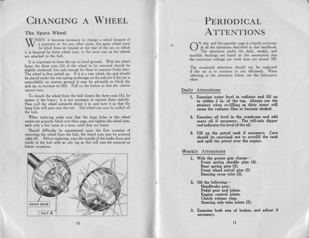
WHEN it becomes necessary to change a wheel because ofa puncture or for any other cause, the spare wheel mustbe lifted from its bracket at the rear of the car, to which
it is fastened by three wheel nuts, in the same way as the wheelsare attached to the hub.
It is important to have the car on level ground. With the wheelbrace the three nuts (A) of the wheel to be removed should beslightly slackened, but only enough for them to unscrew freely later.The wheel is then jacked up. If it is a rear wheel, the jack shouldbe placed under the rear spring anchorage on the axle (or if the car isunavoidably on uneven ground it may be advisable to block thejack up, to increase its lift). Pull on the brakes so that the wheelscannot turn.
To detach the wheel from the hub loosen the three nuts (A), bymean. of the brace; it is not necessary to remove them entirely.Now pull the wheel outwards about i in. and turn it so that thelarge hole will pass over the nut. The wheel can now be pulled offthe hub.
When replacing make sure that the large holes in the wheelcentre are properly fitted over their pegs, and tighten the wheel nuts,each only a few turns at a time, until they are home.
Should difficulty be experienced upon the first occasion ofremoving the wheel from the hub, the wheel nut. may be screwedright off. Before replacing, wipe the outside of the brake drum andinside of the hub with an oily rag as this will ease the removal onfuture occasions.
NUT A
10
11
J
"
PERIODICALATTENTIONS
,. ON this and the opposite page is a handy summaryof all the attentions described in this handbook.
, The attentions under the daily, weekly, andmonthly headings are based on the assumption thatthe maximum mileage per week does not exceed 300.
The occasional attentions should not be neglectedif the car is to continue to run efficiently. Whenreferring to the attentions below, see the lubricationchart.
Daily Attentions
1. Examine water level in radiator and fill upto within 2 in, of the top, Always use thestrainer when re-filling as dirty water willcause the radiator film to hecome choked,
2. Examine oil level in the crankcase and addmore oil if necessary. The tell-tale dipperrod indicates the level of the oil,
3, Fill up the petrol tank if necessary. Careshould he exercised not to overfill the tankand spill the petrol over the engine.
Weekly Attentions
1. With the grease gun charge-Front spring shackle pins (4).Rear spring pins (2).Front wheel swivel pins (2)Steering cross tube (2).
2. Oil the following-Handbrake gear.Pedal gear and joints.Engine control joints.Clutch release ring.Steering side tuhe joints (2).
3. Examine both sets of brakes, and adjust ifnecessary.
11
,
"
:(
I
II
4. Inject high speed grease (such as Messrs.Stemol's "Diamol") into the universal jointat the rear end of the propeUor shaft andyellow grease into the front end of the torquetuhe.
S. Test the tyres for correct pressure and examinethem for cuts.
6. Give one turn to the cap of the luhricator forthe distributor spindle bearing.
PETROL SUPPLY
3. Grease all the hubs as described later.
4. Charge with grease the steering worm casethrough the nipple.
S. Examine the battery and see that theconnections are tight.
6. Give a charge of grease to the nipple on thefan spindle.
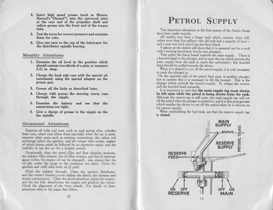
Two important alterations in the fuel system of the Austin Sevenhave been made recently.
All models now have a larger tank which contains when full,rather more than five gallons-the old tank had a capacity of four-and a neat two level petrol tap has been fitted.
A glance at the sketch will show that it is operated not by a cockwith a turning movement, but by two plungers.
That under the fascia board controls the main supply. There isa knurled head to the plunger, and to open the tap which permits themain supply from the tank to reach the carburetter; this knurledhead should be pulled towards the driver.
When it is desired to cut oH the petrol supply, it is only necessaryto push the plunger in.On the opposite side of the petrol feed pipe, is another plunger,
but to operate this it is necessary to lift the bonnet. This is theplunger which controls the reserve supply. To release the reservepull the knurled head outwards.
It is important to. note that the main supply tap must alwaysbe left open while the petrol is being drawn from the tank.Although the reserve tap is still open, the main supply tap will cutoff the petrol when its plunger is pushed in, and it is this arrangementwhich enables the driver to cut oH the petrol when he is driving onhis reserve supply.
When replenishing the fuel tank, see that the reserve supply tapis closed.
Monthly Attentions
1. Examine the oil level in the gearbox whichshould contain two-thirds of a pint, or measure2-2! in. deep.
2. Charge the hack axle case with the special oilmentioned, using the special adapter on thegrease gun.
1
RESERVEFEED
q MAINI, SUPPLY ~
~I ~)1'-- _M!w.~~-~-A~ "
11 " ~
tf' RESERVE.~1/ SUPPLY &;i
r-1 ~,w,~Il
Occasional Attentions
Examine all bolts and nuts, such as road spring clips, cylinderhead nuts, wheel nuts (these three especially when the car is new),examine other parts such as steering connections, the radius rodanchorage below the gearbox, and the torque tube socket, neglectof which points might be followed by an expensive repair, and theinability to use the car for a lengthy period. .
Occasionally clean the petrol filler and float chamber strainers,the radiator filler strainer, the oil filler strainer, and the oil reservoirgauze (when the engine oil can be changed); also ensure that theoil jets, under the plugs on the crankcase. are clean. DrAin thegearbox and refill with fresh oil H pint)
Flush the radiator through. Clean the ignition distributor,and the contact breaker points (adjust the latter), the dynamo andstarter commutators. Clean the shock absorbers, adjust the tAppets,and the fan belt, decarbonize the engine and grind-in the valves.Check the alignment of the front wheels. For details of theseattentions refer to the pages that follow.
(
I
12
ri'~1",
/"<tON OFF
RESERVE
rTj
r\OFF ONMAIN
13
" ,
( The CARBURETTER
iI11
:1
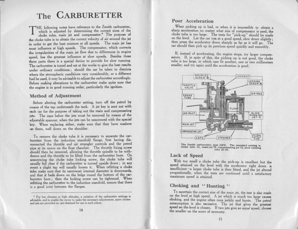
THE following notes have reference to the Zenith carburetter,which is adjusted by determining the correct sizes of thechoke tube, main jet and compensator.' The purpo.e of
the choke tube is to obtain the correct velocity of air around the jetin order to get the best mixture at all speeds. The main jet h..most influence at high speeds. The compensator, which correct.the irregularities of the main jet flow due to differences in engine.peed, has the greatest influence at slow speeds. Besides thesethree parts there is a special device to provide for slow running.The carburetter is tuned and set at the works to give the best resultsunder ordinary conditions; should the car be taken to district.where the atmospheric conditions vary considerably, or a diHerentfuel be used, it may be advisable to.adjust the carburetter accordingly.Before making alterations to the carburetter make quite sure thatthe engine is in good running order, particularly the ignition.
Method of AdjustmentI1I Before altering the carburetter setting, turn oH the petrol by
means of the tap underneath the tank. A jet key is sent out witheach car for the purPose of taking out the main and compensatingjets. The caps below the jets must be removed by mean. of theadjustable spanner, when the jets can be unscrewed with the specialkey. When replacing either, make sure that they have washerson them, well down on the shoulder.
To remove the choke tube it is necessary to separate the car-buretter from the induction manifold flange, first having di.-connected the throttle and air strangler controls and the petrolpipe at its union on the float chamber. The throttle fixing screwshould then be removed, allowing the throttle spindle to be with-drawn and the throttle to be lifted from the carburetter bore. Onunscrewing the choke tube locking screw, the choke tube willusually fall clear if the carburetter is turned upside down; in anyevent a slight tap will usually loosen it. When refitting a choketube make sure that its narrowest internal diameter is downwards,and that it beds down on the ledge round the bottom of the car-buretter bore; then the locking screw can be tightened. Whenrefitting the carburetter to the induction manifold, ensure that thereis a good joint between the flanges.
.Fo, hot dima'" 0' high altitud". a varia,ionof ,h, whu«tt" ",tin.. i.advi..hl,. and'0 ,nahl, th, own" '0 mak,th, n"",my adju"m,nt., 'p'« ohok",nd i'" a« pmvid,donoa" d"tin,d In<u" in ,uohplace,.
14
y
II.
f
II
I
I
'\I
i
"
Poor AccelerationWhen picking up is bad, or when it is impossible to obtain a
.harp acceleration no matter what size of compensator is used, thechoke tube is too large. The tests for" pick-up" should be madeon the level. Let the car run at a good speed, slow down slightly;then press the accelerator down sharply as far as it will go. Thecar should then pick up its previous speed quickly and smoothly.
If, instead of accelerating, the engine stops, try larger compen-.ators. If, in spite of this, the picking up is not good, the choketube is too large, in which case fit another, one or two millimeters.maller, and try again until the acceleration is good.
KNURLEDSCREW B LOCKNUT
CHOKETUSE
AIR HOLE
AIR INLET
MAIN JET
COMPENSAnNG JET
CAPS
Th, Zenith oarbur"'", typ, 22FZ. Th, "an""rd ,"tinQ i,.ohok, tuh, 15. main J" 70. oompen'atin~ J" 75. ,low runuln.'ub, 26.3S.
Lack of SpeedWith too small a choke tube the pick-up is excellent but the
speed attained on the level with the accelerator right down i.insuHicient-a larger choke tube is then fitted, and the jet alteredproportionally, when the tests are continued until a satisfactorymaximum speed is attained.
Choking and" Hunting"To ascertain the correct size of the main jet, the test is also made
on the level at high speed. A jet which is much too large causeschoking, and the engine often runs jerkily and hunts. The petrolconsumption is also excessive. The jet that gives the greatestspeed on the level is chosen. If two jets give an equal speed, choosethe smaller on the score of economy.
15
,
~
~I
11
No Power
When the car gets away badly. and popping-back occurs in thecarburetter when accelerating. the main jet is too small. Thi.
popping-back occurs at irregular intervals. and the engine ha.little power and cannot drive the car at a high speed. Fit largerjets until these explosions in the inlet pipe disappear and then testuntil the right iet has been found.as indicated in previou. paragraph..
The popping-back may also be due to air leaking into the inductionpipe through joints which are not air-tight. to leakage at the extraair valve. or to the valves not closing properly. Test the tappetclearances by the thin blade of the sparking plug and tappet clearancegauge. In some cases popping back is due to the engine being cold.and will cease when it has been running for a little time.
Irre~ular Firin~
The trials of different compensators should take place up anincline, with the engine driving the car in top gear at from 5 to 8m.p.h. The compensator is too large when the engine at thisspeed runs with an irregular. jerky motion; the hunting whichtakes placeat high speed in the case of too large a main jet is foundat low speeds with too large a compensator. The size of thecompensator is decreaseduntil all the cylinders fire evenlyand theexhaust is quite regular. As in the case of the main jet. if twocompensatorsgive equal results, choose the smaller on the scoreof economy. The compensatorplaysa great part in th~ picking-upbut when the sizeof the formeris determinedaccordingto the abovemethod, it is generally suitable for an excellent acceleration.
I
I
I
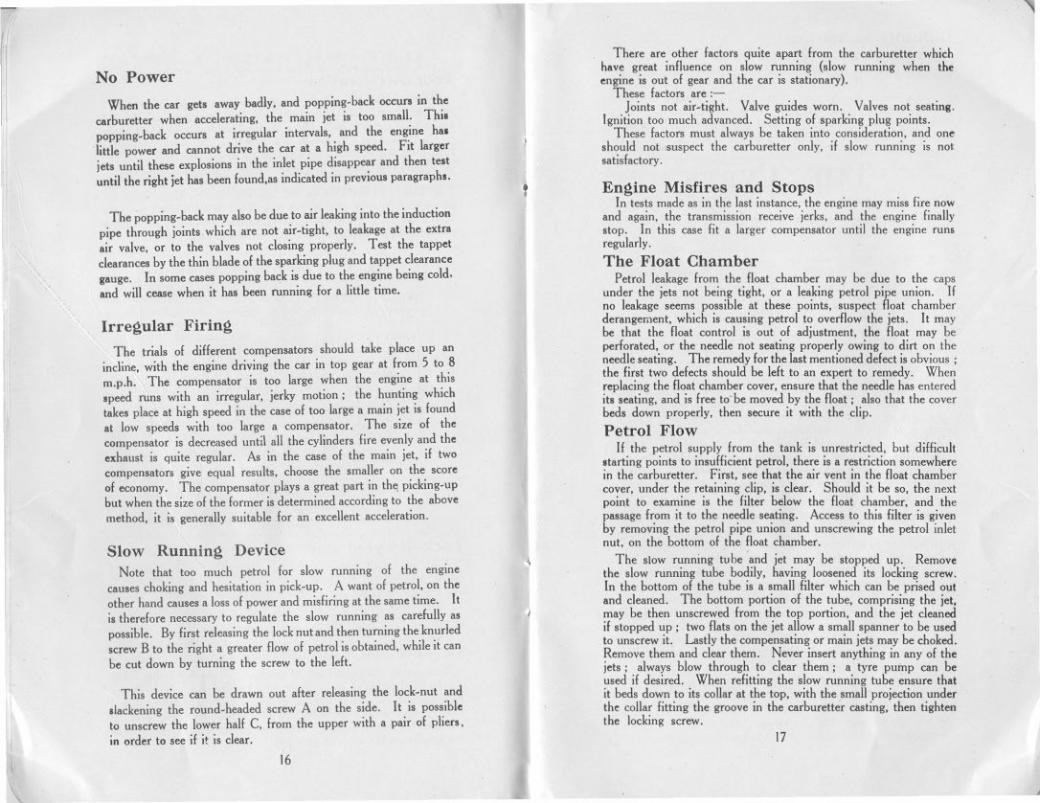
Slow Runnin~ DeviceNote that too much petrol for slow running of the engine
causes choking and hesitation in pick-up. A want of petrol. on theother hand causes a loss of power and misfiring at the same time. Itis therefore necessary to regulate the slow running as carefully aspossible. By first releasing the lock nut and then turning the knurledscrew B to the right a greater flow of petrol is obtained. while it canbe cut down by turning the screw to the left.
I:
\
This device can be drawn out after releasing the lock-nut and.Iackening the round.headed screw A on the side. It is possibleto unscrew the lower half C. from the upper with a pair of pliers.in order to see if it is clear.
16
l .,
II
There are other factors quite apart from the carburetter whichhave great influence on slow running (slow running when theengine is out of gear and the car is stationary).
These factors are:-Joints not air-tight. Valve guides worn. Valves not seating.
Ignition too much advanced. Setting of sparking plug points.These factors must always be taken into consideration. and one
should not suspect the carburetter only, if slow running is notsatisfactory.
tI
En~ine Misfires and StopsIn tests made as in the last instance. the engine may miss fire now
and again. the transmission receive jerks. and the engine finallystop. In this case fit a larger compensator until the engine runsregularly.
The Float ChamberPetrol leakage from the float chamber may be due to the caps
under the jets not being tight. or a leaking petrol pipe union. Ifno leakage seems possible at these points. suspect float chamberderangement, which is causing petrol to overflow the jets. It maybe that the float control is out of adjustment. the float may beperforated. or the needle not seating properly owing to dirt on theneedle seating. The remedy for the last mentioned defect is obvious;the first two defects should be left to an expert to remedy. Whenreplacing the float chamber cover. ensure that the needle has enteredits seating. and is free to' be moved by the float; also that the coverbeds down properly, then secure it with the clip.
Petrol FlowIf the petrol supply from the tank is unrestricted. but difficult
starting points to insufficient petrol. there is a restriction somewherein the carburetter. First. see that the air vent in the float chambercover. under the retaining clip. is clear. Should it be so. the nextpoint to examine is the filter below the float chamber. and thepassage from it to the needle seating. Access to this filter is givenby removing the petrol pipe union and unscrewing the petrol inletnut. on the bottom of the float chamber.
The slow running tube and jet may be stopped up. Removethe slow running tube bodily. having loosened its locking screw.In the bottom of the tube is a small lilter which can be prised outand cleaned. The bottom portion of the tube. comprising the jet,may be then unscrewed from the top portion. and the jet cleanedif stopped up; two flats on the jet allow a small spanner to be usedto unscrew it. Lastly the compensating or main jets may be choked.Remove them and clear them. Never insert anything in any of thejets; always blow through to clear them; a tyre pump can beused if desired. When refitting the slow running tube ensure thatit beds down to its collar at the top. with the small projection underthe collar litting the groove in the carburetter casting. then tightenthe locking screw.
1
~
17
-"

I
!
!f'
I1
lill
Difficulty in StartingThis may be due to several causes-
Float chamber air vent stopped up. Slow running tube stop-ped up. Jets choked up. See previous pages.
Plug points too far apart. See" Ignition System."Ignition lever badly placed. See next paragraph.
With variable ignition there is generally a particularly favourablesetting for easy starting. One who is continually using a car soonrecognises this position.
THE TYRESTyre Pressure
Tbe minimum pressures to whicb hoth front and hack tyresshould be inflated are :-
Model.Inflationp""",,,.
Fmnt'l Reac-I 0,2 1 Reac.1 Pa"eng",.
I
Fully !.den
20I
20 2422 22 26
Lb,. pcc 'q. in
Standacd T Y'eEquipment.
Open Model,Ched Model,
3.50x 19W.M. 3-19 ,im.
H:
,Sbould, due to wear or other causes, the steering o' any time
develop a tendency to wander or show signs of wobble, thIs pressuresbould be increased. It is important that hoth front tyres should bekept at the same pressure. In any event there is no reason why thepressure should not be more than the minimum figure given, assome drivers prefer their tyres harder than do others.
As tyres form such a large item in the running costs of a car it isadvisable to give them periodical examination and attention.
A cursory glance should be given daily to see that none of thetyres is unduly slack, and a weekly test with a suitable gauge shouldbe made to verify the pressures. Occasionally examine the tyretreads for cuts; bad cuts should be vulcanized.
Tyre WearBecause of the turning-in of the wheels towards each other at their -
lowest point, it has been found that the front side tyre wears at itsouter edge. The camber of the road tilts the car towards the left,and the tyres are distorted. It is in the action of recovering theircorrect shape, immediately after contact with the road, that theysuHer abrasion, made more damaging because the gritty substancesnow used on tarmac roads accumulate on the near side and the wheelis running in this grit for most of the time it is on the road. Sochange your front wheels over and thus equalize the wear betweenthe tyres. When both tyres have become worn on the outside edge,change the back wheels with the front wheels. Subsequently thetyres can be turned round, bringing the least worn edge to the out-side. If the front tyres should show premature wear at any timesuspect the tracking of the front wheels. Have it checked, to see ifit is correct, and, if necessary, adjusted (see page 46).
Ii11
18I:
,
.,
The IGNITION SYSTEM
i T!'fE. . recom,!,endations that follow apply to the Lucas. .gn.tlOn eqUIpment.
The set should be examined occasionally and the followingattentions given, only if they seem necessary.
.The Distributor
Tbe distributor cover can be removed on springing aside its twosecuring clips. The electrodes "B" and "H" and the inside of thecover are then accessible for cleaning with a dry duster. See that the
. carbon brush" A" isclean and moves freelyin its holder. The con-tact breaker points canbe similarly cleaned ifrequired. Normally thegap between the con-tacts will not requireadjustment until a con-siderable mileage hasbeen covered, unlessthe points have burned.The work of re-settingthe points, when thishas occurred, should beleft to a skilled mech-anic. For the normaladjustment, first turn
Db"'butor .nd Contact Bre.ker. the engine by the start-A C.'bOnB"".. B B,t,tln, Cam. ing handle until theB Eloo'rod... F Cond.n",. points are seen to beC C,nt"". G .,t,'In, dJ,"ih.tin, f 11 Th I kD Looknu',. arm. U y open. en s ac -
H ',In'In, Eloo'rod.. en the lock-nut (D)J C,n',,' .,,"'.. pi"t. with the ignition span-
ner, and turn the screw of the movable point until the gap is setto the thickness of the gauge on the side of the spanner. Thelock-nut must then be re-tightened.
J
~,I
The Coil and Switchboard.The coil needs no attention apart from keeping the terminals
tight and the top clean.The left-hand switch on the switchboard, additional to con-
trolling the dynamo charge, serves as an ignition switch. Theswitch should be always turned to the" OFF" position whenthe engine is not running, so that the battery does not dischargeby the current continuing to flow through the coil windings.
19
,
-III The warning lamp on the switchboard will light when the switch
is at " Summer t Charge" or "Winter Full c." and the engine isnot running. This lamp also lights when the engine is only idling.Should the bulb of the warning lamp fail, it can be unscrewed fromits locket when the lmall cover plate holding the red glass is removed.The replacement bulb should be a 2.5 volt .2 amp. screw cap type(No. 252 M.E.S.) as originally fitted.
iI
Lubrication.The greaser for the distributor shaft should be given one turn
about every 500 miles. Re-pack the greaser with a good qualityhigh melting point grease when necessary. About every 3,000 milesgive the cam the slightest smear of vaseline, and place a single dropof oil on the pivot "]" on which the contact breaker works.
Renewing High Tension Leads to Distrib-utor and Coil.
When the high tension cables show signs of perishing or cracking.they should be replaced. Use only 7 m.m. rubber covered ignitioncable for all high tension leads.
To make a connection to the distributor or coil terminals. threadthe knurled insulating nut over the lead, bare the end of the cable forabout! of an inch. thread the wire through the brass washer pro-vided, and bend back strands. When the moulded nut is screwedhome, the cable will be securely clamped, and the nut will supportthe cable, and prevent vibration and fracture.
, Ignition FaultsWhen the engine will not fire, or fires erratically. the trouble
may arise from the carhuretter, or petrol supply and not the ignition.A partially choked jet, an incorrect petrol level. or air leaks intothe induction system may be the fault. Equally, sooted plugs canbe suspected. when dismantling and cleaning them will remedythe trouble. If the battery has run down, or its terminals haveworked loose. quite obviously there will be no spark, and the sameresults can be expected if the distributor electrodes and contactbreaker have been neglected and are dirty.
The coil can be tested by removing the cable from the centresocket on the distributor cover, and holding the end of this cable,about! inch from some metal part of the car. while the ignition.witch is on and the engine is turned. A strong and regular sparkwill result if the coil is in order. Clean the top of the coil, anden.ure that its terminals are tight before making this test.
To test for short circuits in the low tension wiring (the cablesfrom the switchboard to coil. coil to distributor. and distributor to
20
- ~
~
chassis) which would equally cause irregular runnmg, have theengine turned while the ignition is switched on, and watch theammeter reading. It should rise and fall as the contact breakerpoints close and open. This test will also indicate if the contactbreaker is functioning correctly. If the contacts remain open, ordo not fully close, the reading will not fluctuate.
If the high tension cables from the distributor to the plugs, are notsecurely attached to the distributor, misfiring may occur. Or,if the rubber insulation on these cables shows signs of perishingand cracking. there may be leakage of the current giving rise to thesame symptoms. Renewing the cables is then the remedy.
If after verifying these points, the trouble remains undiscovered,the equipment should be examined and tested by the nearest servi,edepot of the makers.
Sparking Plugs.Gap Setting. The gap between the sparking plug points should
be .018in. Too wide a gap would cause misfiring. especially at highspeeds and under heavy pulling at Iow speed with an open throttle,while too small a gap causes poor idling. When adjusting the gap.never bend the centre wire.
Cleaning. During the first several hundred miles of operationit may be necessary to clean the sparking plugs. During thisrunning in process, an excess amount of oil is sometimes used. andcarbon may deposit on the sparkling plug insulator causing a foulingcondition that soon disappears when the motor has been well run inand a change of oil has been made.
f
Other Conditions causing Fouled Sparking Plugs:
Poor Grade of Oil. Improper Carburettor adjustment.Poor Grade of Petrol. Excessiveuse of choke.
Faulty cables. Distributor points out of adjustment.
Change Sparking Plugs every 10,000 miles. It is recom-mended that sparking plugs be replacedat intervalsof every 10,000miles.
? When Leaving the CarWhen the car has to be parked or left in the street for any period,
the distributor cover can be lifted. and the rotating distributor armremoved from its mounting above the cam; it just pulls off withoutturning. The car is then secure against any attempts at theft. andthe distributor arm can be carried in the pocket until the car is to beused again. When refitting it. note that the projection up inside itsmoulding, fits the slot cut in the top of the spindle on which ilmounts, so that it is located for correct timing
21

"I
1if
ill
TIMING THE IGNITION
The
COOLING SYSTEM
ill
In the event of the distributor (with or without the dynamo) heingremoved from the car, upon replacement, the timing of the ignitionmust be re-set.
The first operation is to remove all the sparking plugs, exceptthe front-No. I-and turn the crankshaft by the starting handleuntil compression is felt. This means that No. I cylinder will bethe next one to fire.
THE cooling of the engine is maintained by a capacious radiatorwhich should be filled, with rain water, if available, up towithin 2 in. of the top of the filler. The capacity of the
radiator, pipes and cylinder jackets is 9-10pints
~ I
..In Cold Weather
Care should be taken to see that the water is drained oH com-pletely, for,'in case of freezing, it will do harm by lodging in smallspaces and fracture of the cylinder block may result. fn GreatBritain, the climate does not very often call for the cooling system tobe drained, but it is well to err on the right side and take due pre-caution against damage if frost be threatened.
T 0 preve~t the gradual formation of deposits in the coolingsystem, with consequent impeding of the circulation, the 'use ofhard water should be avoided. Rain-waier, syphoned from thetop of the barrel where it is clean, should be used, or, failing that,water that has been boiled,
I.'
Flywheel Timing MarksThen remove the starter motor with its casing (inside the car)
by unscrewing the securing studs, one on each side of the casing,and lifting the assemblyclear verticallyoff the locatingdowel on thecrankcase, A line will be seen on the back of the flywheel. marked1 and 4 (see illustration on page 27). The line is parallel to thethrows of the crankshaft, and when this line is vertical it naturallyfollowsthai Nos. I and 4 pistons are at the top of their stroke. Inthis case, however,we are only dealing with No. 1. Now turn theflywheel until this line is 1t in. to 2 in. before the top centre. (Wecannot quote a definite figure as this depends on the characteristicsof the particular engine). This is the position at which the sparkshould take place at the sparking plug, when the ignition is fullyadvanced, and the ignition lever on the steering wheel is set at thefull advanced position.
Remove the distributor cover by springing back the two securingclips. The small screw on the clip fixing the control arm to thedistributor casing is slackened, the clip being kept at the full ad-vanced position, and the casing turned anti.clockwise until thecontact breaker points just begin to open, this is the position at whichthe spark occurs. The screw should then be re-tightened. Thedirection in which the rotating arm of the distributor is pointingshould be noted, and the distributor cover refitted, and secured in itsproper position by the two clips. A small projection on the casingfits in a recess near one of the clips to secure the distributor coverin its correct position.
~
I
If after this the ignition seems too much or too little advanced,it can be adjusted by loosening the clamping screw of the controlclip and moving the casing relative to the clip a slight amount,anti-clockwise to advance the timing, or clockwise to retard.' Onlyan extremely small movement is required, then tighten the screw.When refitting the starter motor and casing, after timing, the longerset screw is for the near side of the casing. If the leads from thedistributor have been disconnected for any purpose, they must bereplaced correctly in the sequence marked on the distributor cover,thus :-1,3, 4, 2, which is the firing order.
.
Causes of OverheatingOverheating may be attributed to one or more of the following:Slack fan belt. The belt can be tightened by turning the fanspindle in its bracket after loosening the clamping-nut.Excessive carbon deposit in cylinders. See "Running Adjustments."
Running with ignition too far retarded.Using oil of poor quality, or lack of oil in the reservoir. See"Engine Lubrication."
Partial choking of the oil jets, See "Engine Lubrication."
Improper carburetter adjustment, giving a mixture too rich ortoo weak. See "The Carburetter."
Failure of water to circulate, because of choked radiator tubes,water level below the tops of the radiator tubes, or loss of waterthrough leakage from connections.
Overcooling is almost as bad as overheating. If the engine tendsto be too cool, use a radiator muff, or possibly, in winter the fanbelt can be removed without the engine rnnning too hot.
The entire circulating system should be thoroughly flushed outoccasionally. To do this open the drain tap at the bottom, placea hose in the filler, and run fresh water through.
Trouble arising from a damaged radiator generally necessitatesits dismantling and despatch to a repair depot.
lill
23
~','I:
22
"
ill
11
THEGREASE GUN
LUBRICATION.
I'WE are now supplying a type of grease gun in the tool kit
of all Austin cars known as the Enots "Autolub" gun,which incorporates new features by wbich tbe chassis
lubrication of the car is greatly simplified.
Instead of screwing down the plunger spindle, in order to fill theram of the gun, as in the type previously supplied, once the gun ischarged all that is necessary is to keep pushing the ram of the gunagainst the nipple until the contents are exhausted.
I
Choice of Lubricants
EVERY engine and gearboxis tested and filledwith oil suppliedby the Vacuum Oil Co., Ltd. The grade we recommendboth for winter and summer use is Mobiloil RB.
" The following oils are approved ;-
Sternol's W.W. Heavy; Price's Motorine C; Triple Shell;Castrol X.L.; Filtrate Extra Heavy; Duckham's Adcol N.P. 3 ;Silvertown Speedolene B.; Speedwell Sans Egal Zero, and PrattsMedium Heavy.
Use ordinary "enginc" oil in a small oil can, and ordinary yellowgrease for greasing.
Both these lubricants can be obtained from any garage or repair'shop. .
Use Sternol's "Diamol" High Speed Grease for the rearuniversal joint of the drive shaft.
For the rear axle use Jaba Oil C (Johnsons Austin Backaxle Oil)or Mobiloil C.
"00~~1'1
11
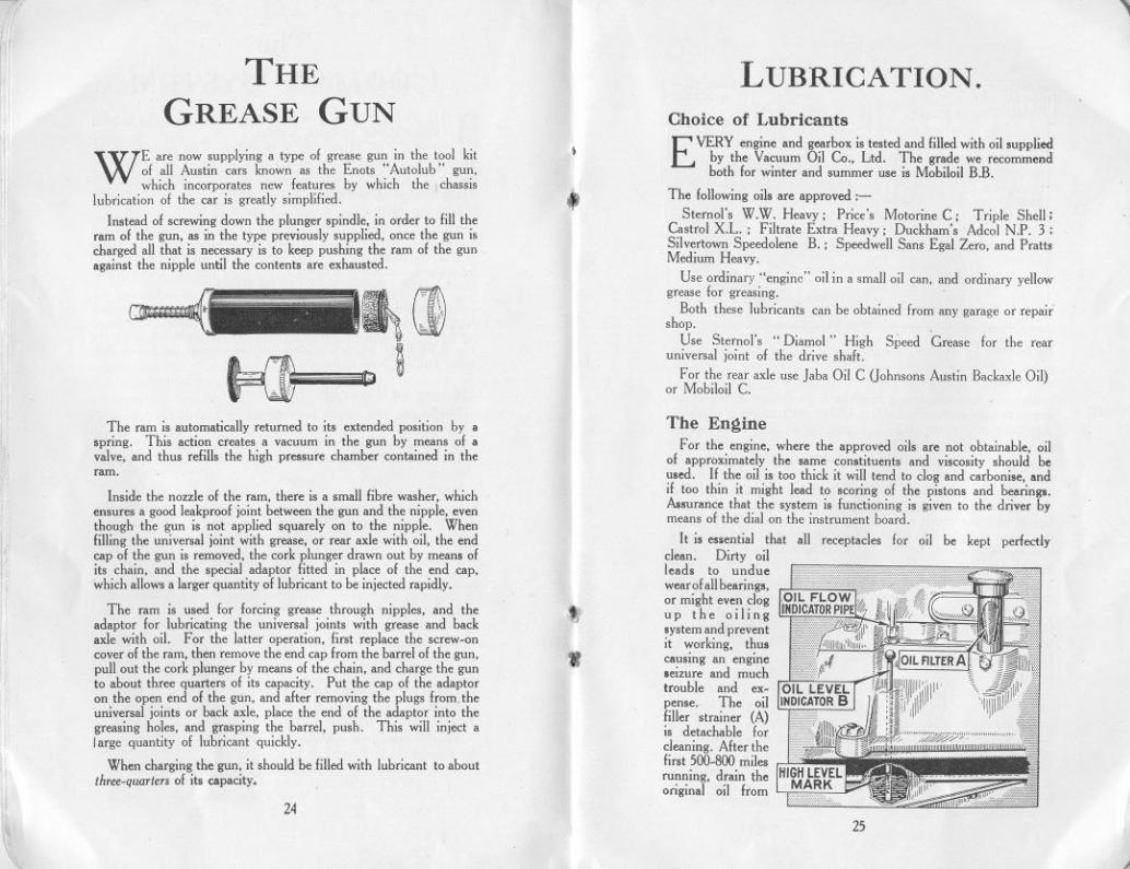
The EngineFor the engine, where the approved oils are not obtainable, oil
of approximately the same constituents and viscosity should beused. If the oil is too thick it will tend to clog and carbonise, andif too thin it might lead to scoring of the pistons and bearings.A.surance that the system is functioning is given to the driver bymeans of the dial on the instrument board.
It is essential that all receptacles for oil be kept perfectlyclean. Dirty oilleads to unduewear of allbearings,or might even clogup the oilingsystem and preventit ~orking, thuscausmg an engmeseizure and muchtrouble and ex-pense. The oilfiller strainer (A)is detachable forcleaning. After thefirst 500-800 milesrunning, drain theoriginal oil horn
The ram is automatically returned to its extended position by aspring. This action creates a vacuum in the gun by means of avalve, and thus refills the high pressure chamber contained in theram.
I
Inside the nozzle of the ram, there is a small fibre washer, whichensures a good leakproof joint between the gun and the nipple, eventhough the gun is not applied squarely on to the nipple. Whenfilling the universal joint with grease, or rear axle with oil, the endcap of the gun is removed, the cork plunger drawn out by means ofits chain, and the special adaptor fitted in place of the end cap,which allows a larger quantity of lubricant to be injected rapidly.
The ram is used for forcing grease through nipples, and theadaptor for lubricating the universal joints with grease and hackaxle with oil. For the latter operation, first replace the screw-oncover of the ram, then remove the end cap from the barrel of the gun,pull out the cork plunger by means of the chain, and charge the gunto about three quarters of its capacity. Put the cap of the adaptoron the open end of the gun, and after removing the plugs from. theuniversal joints or back axle, place the end of the adaptor into thegreasing holes, and grasping the barrel, push. This will inject alarge quantity of lubricant quickly.
When charging the gun, it should be filled with lubricant to aboutthree-quarters of its capacity.
t
jll
"24
25
,J
"I
I@
.11
li
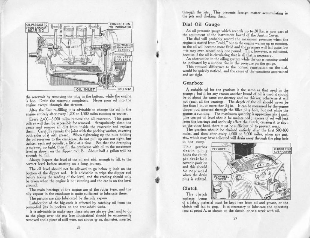
through the jets. This prevents foreign matter accumulating inthe jets and choking them.
,p
,
Dial Oil GaugeAn oil pressure gauge which records up to 20 lbs. is now part of
the equipment of the instrument board of the Austin Seven.The dial will probably record the maximum pressure when the
engine is started from" cold," but as the engine warms up in running,so the oil will become more fluid and the pressure will fall quite Iow-it may even record only one pound. This, however, is sufficient,because if the oil is circulating that is all that is necessary.
An obstruction in the oiling system while the car is running wouldbe indicated by a sudden rise in the pressure on the gauge.
This unusual difference to the normal registration on the dial,would be quickly noticed, and the cause of the variations ascertainedand set right.
;!I.
.il,.
11,
'11
the reservoir by removing the plug in the bottom, while the engineis hot. Drain the reservoir completely. Never pour oil into theengine except through the strainer.
After the first re.filling it is advisable to change the oil in theengine entirely after every 1,200 to 1,500 miles running or sooner.
Every 2,400-3.000 miles remove the oil reservoir. The gauzeoil tray will then be accessible for removal. Scrupulously clean thegauze and remove all dirt from inside the reservoir and replacethem. Carefully remake the joint with the packing washer, coveringboth sides of it with grease. When tightening up the nuts holdingthe oil reservoir to the crankcase, do not pull up one nut tight, buttighten each nut equally, a little at a time. See that the drainplugis screwed up tight, then fill the crankcase with oil to the maximumlevel as shown on the dipper rod, B. About half a gallon will beenough to fill.
Always inspect the level of the oil and add. enough to fill, to thecorrect level before starting on a long journey. .
The oil level should not be allowed to go below 1 inch on thebottom of the dipper rod. It is advisable to wipe the dipper rodbefore taking the reading of the level. and the reading should onlybe taken when the engine i. not running and the car is on the levelground.
The main bearings of the engine are of the roller type, and theoily vapour in the crankcase is quite sufficient to lubricate these.
The pistons are also lubricated by the oily vapour.Lubrication of the big-ends is effected by catching oil from the
pump.fed jets in pockets on the crankshaft web..It is advisable to make sure these jets are always clear and to do
10 the plugs over the jets (see illustration) should be occasionallyremoved and a piece of stiff wire, not above 11rin. diameter, inserted
f
.
GearboxA suitable oil for the gearbox is the same as that used in the
ongine; but if for any reason another brand of oil is used it Ihouldbe of about the same consistency and no thicker, otherwise it willnot reach all the bearings. The depth of the oil should never beless than I in. or more than 21 in. It can be measured by the enginedipper rod inserted through the filler plug hole, but not while theengine is running. The maximum quantity is approximately i pint.The correct oil level should be maintained; excess of oil will leakfrom the bearings and seriously affect the clutch, causing it to slip;on the other hand there must be sufficient oil to prevent wear.
The gearbox should be drained entirely after the first 500.800miles,and then after every 4,000 or 5,000 miles, when any grit,etc.. which may have collected will drain away through the plug holein the sum p.
I ,,'(~The gearbox IFLYWHEEL~drSln plugholds the clutchpit drainholecover in positionand this shouldbe replacedwhen the drainplug is refitted.
"
11'"
I."
1I11
Clutch D::::1(!~"It,The clu~ch ~ ~ ",.urfaces bemg = -=of a fabric material must be kept free from oil and grease, or theclutch will fail to grip. It is necessary to lubricate the operatingring at point A, as shown on the sketch. once a week with oil.
27
\1' 26
,,

~r/
1
ilI
Steerin~ GearTo obtain easy steering it is important to give it regular attention
as regards lubrication. The grease gun nipple is on the top of theworm case, and if a charge is given once a month it is sufticientto lubricate the bearings of the worm and worm wheel and alsolubricate the worm itself. However, if too much grease is injectedat this point, it will get up the column and exude round the steeringwheel. The bearing at the top of the column, just under thesteering wheel can be given a little oil from the oil.can. The steeringconnections on the side rod are best lubricated by means of anoil-can which ejects the oil under pressure, into the sockets,andthe nipples at the end of the cross rod should be given a charge ofgrease once a week.Rear Axle
For the rear axle, attention every 1,200 to 1,500 miles shouldbe sufficient. Jaba Oil Cor Mobiloil C should be used. It is injectedinto the axle, using the special adapter on the grease gun barrel. Firstremove the plug, then place the end of the adaptor into the greasinghole, and grasping the barrel of the grease gun, push. When re-placing the plug see that the washer is not omitted. The plug alsoserves as an oil level indicator, therefore do not replace the plug atonce, which will give time for the superfluous oil to run out, if toomuch lubricant has been injected. This is most important, becauseif the axle is overfilled, the lubricant may leak through on to thebrakes and render them ineffective.
If possible one of these oils should always be used. but in cas..where supplies are not immediately procurable, obtain a worm oil ora gear oil of medium viscosity.
Front Axle
The swivel pins are lubricated with the grease gun and shouldreceive attention once a week.
"I
~
-Radius Rod Anchora~e
Oil should be applied occasionally to the cups and ball flange,forming the radius rod anchorage on the front cross member, justbelow the rear of the gearbox.
IVVindscreen VViper
A drop of thin oil should be occasionallyapplied to the wind-.creen wiper mechanism-say, once a month. A small screw(except in the T rico model) is removable from the top of the casingallowing the oil to be injected.
I,
I.
Fan
11
The fan bearing requires a charge of grease once a month throughthe nipple on the fan bracket.
I
1
~
Rear Universal JointFor the rear universal joint, Sternol's "Diamol" "high speed"
grease should be used. It will remain in the joint longer than theordinary yellow grease.
The rear universal joint being of metal should be ODe of thepoints to have strict weekly attentioD, The car is moveduntil the plug in the universal joint is facing upward. (if it i. notalready so) and the grease is injected in the same manner as is usedfor oiling the back axle. Access is gained by movin'g aside a smallcover in the floor of the body. This same cover gives access to the'plug on the end of the torque tube which should receive ordinaryyellow grease every week.
Brake Gear
On each of the rear wheel brakes there is a sell-lubricating bushfor the cam spindle bearing, and there is, therefore, no greasing
. point on either. These and all other joints, etc., should be oiledonce a week.
The front wheel brake cam spindle is lubricated from the swivel pinas shown at B, in the illustration on page 30.
Grease NipplesIf a grease nipple gets choked, unscrew and remove it. It can
usually be cleared by soaking it in paraffin or petrol, and syringingeither of these through it. but should it be found impossible to clearit, fit a new nipple in its place.
Hli
Road Sprin~sThe rear ends of the rear road springs where they are attached to
the axles are provided with greasing nipples, and should be given acharge once a week if the car is continually used. After a longperiod of use it is advisable to lubricate the leaves of the springwith a warm mixture of white lead and tallow in equal parts. Thiscan best be applied with a stiff brush, the leaves being eased apartby a screwdriver; first jack up the car, not under the axles nor theradius rods, but under the frame to take the weight off the springs.The rear of the car can be jacked up one side at a time. The bestpoint of the frame at which to apply the jack is each end of the rearcross-member. At the front, as there is only one transverse spring,the whole of the car must be lifted, and as a safety measure, the rearwheels should be "scotched" to prevent the car running off thejack. A short stiff bar is placed across the frame, just forward of theengine oil reservoir, and behind the spring, and the jack lifts thecar from the centre of this bar. Block the jack up for this work,with a wood block, to avoid making excessive lift.
:(
28 29
..J
rSWIVEL PIN
lOCKING PIN
BRAKE lEVER CONNECTION
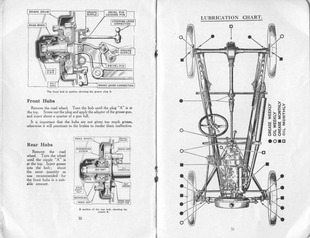
Tb. f.oo, bob io ",dOD. .bowio' ,b. , ,ID, A.
Front Hubs
~IRemove the road wheel. Turn the hub until the plug" A" is at
the top. Screw out the plug and apply the adapter of the grease gun,and inject about a quarter of a gun full.
It is important that the hubs are not given too much grease,otherwise it will penetrate to the brakes to render them ineffective.
Rear Hubs
11
r
Remove the roadwheel. Turn the wheeluntil the nipple "A" isat the top. Inject greaseinto the hub; aboutthe same quantity aswas recommended forthe front hubs is a suit-able amount.
If
.~,\
A ."dOD of ,b. .m bob. .bowio' ,b.oi"l. A.
30
LUBRICATION CHART.
>: ~>-:.J :E:;.J:s: I- J:::::~~I-:;::s::::E:Z
ILl 0ILl ILl""'"
I/!:;:I/!'~-'~..J0::-0=-0000
eo_a
"
31)
"
1/1
7 H.P. SPORTS ENGINEconstantly being fed to the supercharger. If the supercharger hasbeen well run in. say 1.000miles. the amount of oil can be slightlyreduced by means of the adjuster on the supercharger oil pump.
For lubricating the supercharger use Mobiloil "TT."
..
(Supercharged and Unsupercharged).MAINTENANCE INSTRUCTIONS
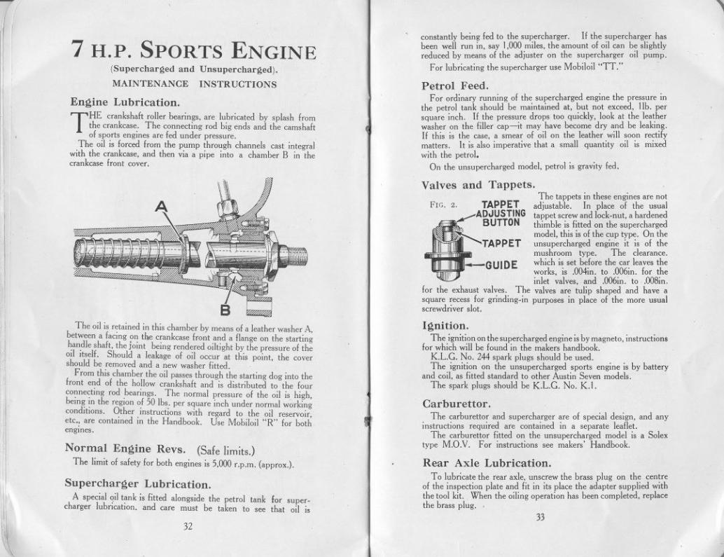
Engine Lubrication.
THE crankshaft roller bearings. are lubricated by splash fromthe crankcase. The connecting rod big ends and the camshaftof sports engines are fed under pressure.
The oil is forced from the pump through channels cast integralwith the crankcase. and then via a pipe into a chamber B in thecrankcase front cover.
Petrol Feed.For ordinary running of the supercharged engine the pressure in
the petrol tank should be maintained at. but not exceed. lib. persquare inch. If the pressure drops too quickly. look at the leatherwasher on the filler cap-it may have become dry and be leaking.If this is the case. a smear of oil on the leather will soon rectifymatters. It is also imperative that a small quantity oil is mixedwith the petrol.
On the unsupercharged model. petrol is gravity fed.
iI
Valves and Tappets.The tappets in these engines are not
adjustable. In place of the usualtappet screw and lock-nut. a hardenedthimble is fitted on the superchargedmodel. this is of the cup type. On theunsupercharged engine it is of tbemushroom type. The clearance.which is set before the car leaves theworks, is .004in. to .006in. for theinlet valves. and .006in. to .008in.
for the exhaust valves. The valves are tulip shaped and have asquare recess for grinding-in purposes in place of the more usualscrewdriver slot.
FIG. 2. TAPPETADJUSTING
~ BUTTON
~TAPPETI
,I
GUIDE
11,.
The oil is retained in this chamber by means of a leather washer A,between a facing on the crankcase front and a flange on the startinghandle shaft. the joint being rendered oiltight by the pressure of theoil itself. Should a leakage of oil occur at this point. the covershould be removed and a new washer fitted.
From this chamber the oil passes through the starting dog into thefront end of the hollow crankshaft and is distributed to the fourconnecting rod bearings. The normal pressure of the oil is, high.being in the region of 50 Ibs. per square inch under normal wor~ingconditions. Other instruciions with regard to the oil reservoir.etc.. are contained in the Handhook. Use Mohiloil "R" for bothengmes.
Ignition.The ignitiononthe superchargedengineisby magneto,instructions
for which will be found in the makers handbook.K.L.G. No. 244 spark plugs should be used.The ignition on the unsupercharged sports engine is by battery
and coil, as fitted standard to other Austin Seven models.The spark plugs should be K.L.G. No. K.!.
Carburettor.
The carburettor and supercharger are of special design. and anyinstructions required are contained in a separate leaflet.
The carburettor fitted on the unsupercharged model is a Solextype M.O.V. For instructions see makers' Handbook.
If
"I
iJ1
illI!
Normal Engine Revs. (Safe limits.)The limit of safety for both engines is 5.000 r.p.m. (approx.). Rear Axle Lubrication.
To lubricate the rear axle. unscrew the brass plug on the centreof the inspection plate and fit in its place the adapter supplied withthe tool kit. When the oiling operation has been completed. replacetbe brass plug. .
1('ifSupercharger Lubrication.
A special oil tank is fitted alongside the petrol tank for super-charger lubrication, and care must be taken to see that oil is
33
;';Ii~~
32
,
'"
11 THE LAMPS
~
THE head lamps are fitted with Lucas-Graves bulbs whichare special double filament bulbs giving a normal drivingbeam or an anti-dazzle light according to the positon of the
change-over switch on the steering column.It is of the utmost importance that the lamps should be set
correctly in relation to the road and we recommend that they bealigned so that the normal driving beams are projected straightahead, i.e., the beams should be parallel to the road and to eachother. It will be appreciated that if the lamps are out of alignmentand are tilted upwards the anti-dazzle beam will be projected abovethe horizontal, thus defeating the object of the scheme.
The alignment of the lamps is very easily carried out, as they arefixed on an adjustable mounting which is locked by a single nutsituated under the mud wing.
When ordering spare bulbs, specify Lucas-Graves type and statevoltage and wattage. See that the new bulb is inserted properlyso as to throw the dipping light downward.
When fitting bulbs, it is important to remember that the lampfronts are not interchangeable. The ribs in the glasses must bevertical so that care must be taken that they are not accidentallychanged over from one lamp to the other.
The switch controlling the change-over from the normal to thedipped beam, is mounted on the steering column, and is easilyaccessible to the driver when meeting oncoming traffic. Advantagemay be taken of the dipped beam when driving in fog, as the lightis concentrated on the road, instead of causing the" white sheet"effect, which a normal beam of light gives when penetrating fog.
Bulb ReplacementTo remove the front of the head lamps for a bulb replacement
slacken the fixing screw at the bottom of the lamp and swing it asidefrom the slot. The front can then be withdrawn. When replacingpress the front on to the lamp body, locating the top of the rim first.Finally swing the screw into the slot and tighten it to lock the frontin position. It should be noted in the case of lamps not mountedvertically, that the fronts of the lamps must not be interchanged,otherwise the lenses in the glass will not be vertical.
In the case of a tail lamp bulb replacement, the front is removedby turning it and then withdrawing it from its base.
Bulb SizesThe sizes of the bulbs are:- Head, No. 612L.G.D.; Dim,
BAS No. 8 S (S.P.); Tail, BAS No. 8 S (S.P.)
The ReflectorsThe reflectors of the lamps are covered with a protective coating,
.nd any marks can be easily removed by means of a soft cloth.On no account use any metal polish on reflectors.
ELECTRICALEQUIPMENT
I1
THE lighting and starting units on the Austin Seven carare arranged for wiring on the single wire system, the returnpath of the current being provided by the frame instead of a
second wire. It is essential that all units are in metallic contactwith the frame.
Should difficulties arise that cannot be understood or remediedIrom the information given below, application .hould at once bemade to the Austin Service Department or the nearest servicedepot of the makers of the equipment.
DynamoThe dynamo is a simple self-regulating third brush machine.
The only parts calling for any attention are the commutator andbrushes, which are readily accessible when the cover is removed.The commutator surlace must be kept clean and free from any oil orbrush dust. It may be cleaned with ordinary soft rag, but if it hasbeen neglected use fine glass paper. Blow away any carbon dust,see that the carbon brushes are wearing evenly and that the armsmove freely on their pivots. To fit a new brush, it is only necessaryto remove the single screw to withdraw the worn brush from itsholder.
The dynamo bearings are packed with grease belore leaTIng theworks and do not require oiling. When the car is overhauled, it isadTIsable to have the machine dismantled and the bearings repackedwith grease. This work is preferably carried out by a Lucas ServiceDepot.
Dynamo Field Fuse.A fuse is provided in the dynamo field circuit to protect the
machine in the event of anything being wrong in the chargingcircuit, e.g., a loose or broken battery connection. The fuse is of thecartridge type and is housed along with the half charge resistancein a small rectangular unit fixed on the dynamo yoke. If the dynamofails to charge the battery at any time (indicated by no chargereading being given on the ammeter during day time running)inspect the fuse and if it has blown, replace it with the spare fuseproTIded. If the new fuse blows alter starting up, the cause of thetrouble must be found, and we advise that the equipment is examinedby one of our Service Depots. Never fit any fuse other than theLucas standard fuse as originally fitted. The size of the fuse ismarked on a coloured paper slip which can be seen inside the fuse.
I'
III
I
,,1111
III
34 Starting MotorThe commutator is accessible on remoTIng the clip secured
cover. The unit requires very little attention beyond keeping
~!35
j
,. "
't'I' the commutator clean and Iree from oil, brush dust, etc., as In thecase of the dynamo. Before starting from cold do not neglectthe preliminary precautions that you would ohserve if starting byhand, such as flooding the carburetter, etc. Remember thatalthough the starter will turn the engine over, however stiff, it isadvisable to crank the engine over by hand two or three revolutionsas this will considerably diminish the load for starting.
If the starter pinion jams in mesh with the flywheel ring whenoperating the starting motor switch, usually it can be released byputting the gear lever into top gear, and moving the car bodilybackward and forward. If this plan is ineffectual the starter willhave to be dismantled.
Never use the starting motor to propel the car, as it throws too,evere a strain on the battery and the motor.
If the engiqe does not start at the first attempt, do not press the,tarter switch until the engine has come to rest. If this precautionis not adopted. the starter ring teeth on the flywheel cover, or the.tarter pinion teeth, may be damaged.
The ammeter gives an indication that the system is functioningsatisfactorily. For example if no reading is given on the charge.ide of the scale when the ignition and charging switch is in the"Winter Full C" position and the car is running at say 20 m.p.h.with no lights on, then a fault in the dynamo charging circuit isindicated.
To determine the output of the dynamo, switch off all the lightsand add the amount of current used for ignition (about 2 amperesat normal speeds) to the reading given on the ammeter.
The amount of current used for ignition may be somewhat higherthan the above figure when starting. The ammeter does not indicatethe amount of current used by the starter.
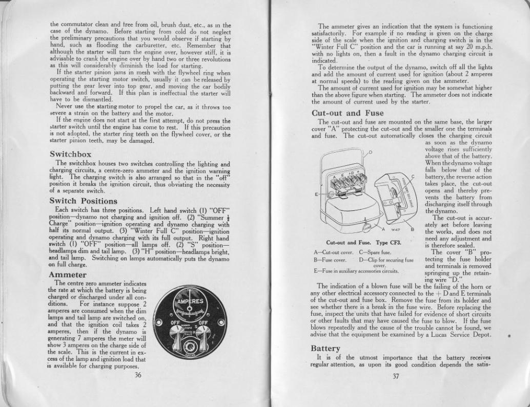
Cut-out and FuseThe cut-out and fuse are mounted on the same base, the larger
cover "A" protecting the cut-out and the smaller one the terminalsand fuse. The cui-out automatically closes the charging circuit
as soon as the dynamovoltage rises sufficientlyabove that of the battery.When the dynamo voltagefalls below that of thebattery, the reverse actiontakes place, the cut-outopens and thereby pre-vents the battery fromdischarging itself throughthe dynamo.
The cut-out is accur-ately set before leavingthe works, and does notneed any adjustment andis therefore sealed.
The cover "B" pro-tecting the fuse holderand terminals is removedspringing up the retain-ing wire "D."
The indication of a blown fuse will be the failing of the horn orany other electrical accessory connected to the + D and E terminalsof the cut-out and fuse box. Remove the fuse from its holder andsee whether there is a break in the fuse wire. Before replacing thefuse, inspect the'units that have failed for evidence of short circuitsor other faults that may have caused the fuse to blow. If the fuseblows repeatedly and the cause of the trouble cannot be found, weadvise that the equipment be examined by a Lucas Service Depot.
",
,Y==- lDSwitch box
The switchbox houses two switches controlling the lighting andcharging circuits, a centre-zero ammeter and the ignition warninglight. The charging switch is also arranged so that in the "off"position it breaks the ignition circuit, thus obviating the necessityof a separate switch.
Switch PositionsEach switch has three positions. Left hand switch (1) "OFF"
position-dynamo not charging and ignition off. (2) "Summer 1Charge" position-ignition operating and dynamo charging withhalf its normal output. (3) "Winter Full C" position-ignitionoperating and dynamo charging with its full output. Right hand.witch (I) "OFF" position-all lamps off. (2) "S" position-headlamps dim and tail lamp. (3) "H" position-headlamps bright,and tail lamp. Switching on lamps automatically puts the dynamoon full charge.
AmmeterThe centre zero ammeter indicates
the rate at which the hattery is beingcharged or discharged under all con-ditions. For instance suppose 2amperes are consumed when the dimlamps and tail lamp are switched on,and that the ignition coil takes 2amperes, then if the dynamo isgenerating 7 amperes the meter willshow 3 amperes on the charge side ofthe scale. This is the current in ex-cess of the lamp and ignition load thatis avail.ble for charging purposes.
36
III
E.
Cut.out and Fuse. Type CF3.
A-Cut.out <over. C-Sparo fu".B~Fu" <over. D-Clip fo, ,eming fu"
coveLE-Fu,e in auxili"y """'on,, ci"uit>.
Ij
I
'"
""
'11
:n,
:
IiliI
tl'I.'
I,
t..."
~
.Battery
It is of. the utmost importance that the battery receive.regularattention, as upon its good condition depends the satis-
37
,

I
il'I'
I;
'' "i
I iI I
l' i
tI1:'i,il
"
't
l
1111
11
'il
!
II
,I
"
'"l!I'
'11.
~~\t\
.
factory running of the starting motor, the fnnctioning of the ignition,and the illumination of the lamps.
At least once a month the vent plugs in the top of the batteryshould be removed and the level of the acid solution examined.If necessary, distilled water, which can be obtained at all chemistsand most garages, should be added to bring the level up to i to t aninch above the plates. If, however, acid solution has been spilled itshould be replaced by a diluted sulphuric acid solution of I .285specific gravity. It is important when examining the cells thatnaked lights should not be held near the vents on account of thepossible danger of igniting the gas coming from the plates. It isadvisable to complete the inspection by measuring the specificgravity of the acid, as this gives a very good indication of the state ofcharge of the battery. An instrument known as a hydrometer isemployed for this purpose; this may be obtained at the AustinService Department, or from the service depots of the makers ofthe equipment.
Charging SwitchThe chargirig (left hand) switch should be kept at the position
appropriate to the season. For cars running under average con-ditions this will ensure that the battery is kept in form without beingovercharged. However, in some circumstances it may be advisableto use the switch out of season. Thus if in winter the car is runregularly during the day with practically no night running, resultingin the battery always being fnUy charged (hydrometer reading I .285or over), the switch should be kept in the "Summer t Charge"position when the engine is running. Or conversely, if exceptionaluse of the starter and lamps is made in the summer, causing thebattery to be continuously in a Jow state of charge (hydrometerreadings of 1.200or under), the switch should be kept at the "WinterFull C" position while the engine is running. Always keep theswitch at the " Off" position when the engine is at rest.
Should the state of the battery be continually bad, see that allits connections through the starter switch to the switchboard aretight and unbroken, and that no wire has a chafed covering, allowingleakage of current to the frame.
The ElectrolyteWhen the battery arrives empty (as in the case of cars sent abroad)
the first thing to do is to fill and charge it.This means that a fluid is prepared composed of one part (by
volume) of pure brimstone concentrated sulphuric acid with threeparts (by volume) of distilled water. Mix these in a glazed earthen-ware vessel. Creat care must be taken in this operation. Add theacid in very small quantities, almost drop by drop, and stir with aglass rod.
Never add the water to the acid. This is highly dangerous,and a serious explosion may result.
This mixing generates heat, and it is important that the electrolyte(as the mixture is called) should not be used in the battery beforeit has been allowed to cool. Pour the electrolyte into the cells of the
38
"'hattery by means of a lead, glass or celluloid funnel. until it corn.pletely fills the cells to the top of the vent hole, Allow the batteryto remain in this condition for 10 minutes or so, then put in moreacid so that eachcell is againfilledto the samepoint with electrolyte.The electrolyte will have a specific gravity of 1,285 when fnllycharged, Batteries may be charged at almost any service station.
,
HEJ'DLAMPS EACH CONTI'JN TWO BULBS
ONE BULB WTH Ml'JN DRiVINGAND DIPPING FILI'JMENTSONE PILOT BULB FOR PARKING OR TOWN DRIVING
,..','
{..I. , "EARTH.,
0"SW"':H.
/~-,
p~l~j \= i
II
eUHuT. III
POSITIVE CCEO FOR I
AU"UARIES." '
Du
~1tO
O)CONNEc;ED W'EARTH~
"~
SWITCHBOARD
HORN.
01 0
;0 HORN
BunON
I,""'ON WL
DIST".UTOR'
FIRING ORDER1.34.2.
T,"LcAMP.
""'TTERY
j'jJ1 STARTER.
STARTER""TCH.
39
r RUNNINGADJUSTMENTS
THE adjustments set out below are all tbat the owner willfind it necessary to make to keep the car in good runningorder.
~
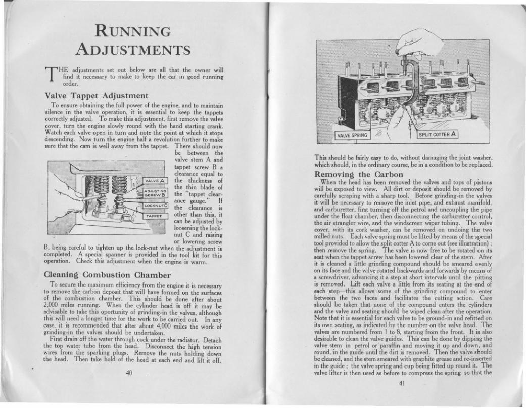
Valve Tappet AdjustmentTo ensure obtaining the lull power 01 the engine, and to maintain
silence in the valve operation, it is essential to keep the tappetscorrectly adjusted. To make this adjustment, lirst remove the valvecover, turn the engine slowly round with the hand starting crank.Watch each valve open in turn and note the point at which it stopsdescending. Now turn the engine hall a revolution lurther to makesure that the cam is well away lrom the tappet. There should now
be between thevalve stem A andtappet screw B aclearance equal tothe thickness 01the thin blade 01the "tappet clear.ance gauge." Ifthe clearance isother than this, itcan be adjusted byloosening the lock.
- nut C andraisingor lowering screw
B, being carelul to tighten up the lock-nut when the adjustment iscompleted. A special spanner is provided in the tool kit lor thisoperation. Check this adjustment when the engine is warm.
This should be lairly easy to do, without damaging the joint washer,which should, in the ordinary course, be in a condition to be replaced.
Removing the CarbonWhen the head has been removed the valves and tops 01 piston.
will be exposed to view. All dirt or deposit should be removed bycarelully scraping with a sharp tool. Before grinding-in the valve.it will be necessary to remove the inlet pipe, and exhaust manilold.and carburetter, lirst turning 011the petrol and uncoupling the pipeunder the lIoat chamber, then disconnecting the carburetter control,the air strangler wire, and the windscreen wiper tubing. The valvecover, with its cork washer, can be removed on undoing the twomilled nuts. Each valve spring must be lilted by means 01the specialtool provided to allow the split cotter A to come out (see illustration) ;then remove the spring. The valve is now Iree to be rotated on itsseat when the tappet screw has been lowered clear 01 the stem. Alterit is cleaned a little grinding compound should be smeared evenlyon its lace and the valve rotated backwards and lorwards by means 01a screwdriver, advancing it a step at short intervals until the pittingis removed. Lilt each valve a little Irom its seating at the end 01each step-this allows some 01 the grinding compound to enterbetween the two laces and lacilitates the cutting action. Careshould be taken that none 01 the compound enters the cylindersand the valve and seating should be wiped clean alter the operation.Note that it is essentiallor each valve to be ground-in and refitted onits own seating, as indicated by the number on the valve head. The.alves are numbered Irom I to 8, starting Irom the Iront. It is alsodesirable to clean the valve guides. This can be done by dipping thevalve stem in petrol or parallin and moving it up and down, andround, in the guide until the dirt is removed. Then the valve shouldbe cleaned, and the stem smeared with graphite grease and re-insertedin the guide: the valve spring and cup being fitted up round it. Thevalve lilter is Ihen used as belore to compress the spring so that the
.
~
Cleaning Combustion ChamberTo secure the maximum elliciency Irom the engine it is necessary
to remove the carbon deposit that will have lormed on the surfaces01 the combustion chamber. This should be done alter about2,000 miles running. When the cylinder head is 011 it may beadvisable to take this qportunity 01 grinding-in the valves, althoughthis will need a longer time lor the work to be carried out. In anycase, it is recommended that alter about 4,000 miles the work 01grinding-in the valves should be undertaken.
First drain 011the water through cock under the radiator. Detachthe top water tube Irom the head. Disconnect the high tensionwires from the sparking plugs. Remove the nuts holding downthe head. Then take hold 01 the head at each end and lilt it off.
40
41
-,
I
I
J

'"
f
!tld":
:1.1
n
~
Q
--
split cotter can be refitted. The smaller diameter of the completecotter should be uppennost, and the cotter should be fitted down onto the collar at the bottom of the stem. The grease on the stemwill help to hold it in position while the lifter screw is slackened, toallow the valve cup to come down over the cotter. It is easiest iftheend valves are fitted first, working towards the centre ones. Checkthe dearance by means of the tappet dearance gauge, and as ameasure of caution, repeat the checking after the car has run 100 miles,as the valves have a tendency to bed down again. When refitting themanifolds ensure that the joints are good. The cylinder head jointwasher should be replaced, copper side downward, with a littlegraphite grease smeared over each side, to make a good joint and toprevent it sticking wben the head has next to be lifted. Whenreplacing the head take care to tighten the nuts evenly. Don'tforget, after replacing the head, to refill the radiator.
Lifting the Cylinder BlockFor access to the pistons (except the piston crowns), and the
connecting rods, or for fitting a new tappet plunger or guide, orvalve guide, it is necessary to lift the cylinder block. The threenuts on the distributor side are easily removed, also the three barrelnuts on the valve side can be removed without difficulty whenthe valve cover has been taken off. For access to the nut at thefront of the cylinder block the dynamo and casing with the fanbracket and fan, must be lifted dear. First pull the ignition leadsand the lead from the coil, from their sockets in the distributor cover,Disconnect the dynamo and the ignition control, and remove thefan belt. The casing is secured by three set screws and a nut. Withthe casing removed, the front cylinder block nut is accessible. Foraccess to the rear nut of the block, it is advisable to lift the starter-motor and casing, from its mounting over the flywheel. This isdone by removing the two set screws, and lifting the casing dearvertically off its positioning do~el. The cylinder block can belifted when the lower hose connection has been removed. Whenrefitting the starter-motor casing, the larger set screw is required atthe nearside of the casing. There is no joint washer between thiscasing and the crankcase, but paper joint washers are used betweenthe cylinder block and the crankcase, also under the dynamo casing.These joints must be oil-tight. When refitting the cylinder block itis necessary to use sleeves on the pistons to compress the rings.These piston ring sleeves are among the extra tools obtainable fromthe Service Department of the Austin Motor Co., Ltd. It will benecessary to retime the ignition after re-assembling.
To adjust the foot brake: Under the car and approximately underthe foot controls is a wing nut (C).This must bescrewed towardsthe front of the
engine until thebrakes go full onwhen the pedal isdepressed a b 0 u t2in. When theped~1 is up, thebrake shoes shouldnot rub the wheeldrums in whichthey operate.
For adjusting the rear brakes, which may be necessary afterre-lining the shoes, an individual adjustment for each of the rearbrake cables is provided. A screwed end, to which the cable isattached, screws into the front fork-end, which secures the cable tothe compensating tube lever. By removing the fork-end from thelever (a pin,secured by a split-pin, holds it) the fork can be screwedfurther on or off the screwed cable end to effect the adjustment.
The cable must not be twisted while this isbeing done. To test whether both brakes
engage equally atthe same time,jack-up the backaxle, and with thebrake pedal presseddown, turn eachwheel by hand tojudge the brakingeffect.
Having done thisthe hand brakelever should be ad-justed. This isdone from underthe car, by hand.A wing nut isprovided by meansof which the slackbetween the handbrake lever and thebrake gear is takenup.
The hand brakelever must bebe pushed forwardto its limit, that ISthe brake must be
Adjusting the BrakesBoth the hand brake and the foot brake operate on all four wheels.
They require adjusting when the hand lever can be pulled right backto the full travel on the rack, and when the pedal can be pushednearly to the floor-board without either brake holding the wheels.The car should never be taken out when in this condition, butshould be attended to at once. 43
42
.

"
right off. Then turn the wing nut clockwise until the hand brakelever will only move freely one notch in the rack, withoutmoving the brake mechanism.
If this short movement is made without beginning to operate thebrakes, it indicates that the brake shoes will not rub against thedrums when the hand brake lever is in the "off" position; and thatthe adjustment has been properly made.
Re-lining the BrakesTo re.line the brakes it is necessary first to remove the wheel,
and then the brake drum, by unscrewing the three screwdriver
as closely as possible, using the wheel nuts to draw the two halvestogether. Then use the hub extractor a second time, and so removethe hub together with bearing and packing. The brake shoes cannow be pulled off the cam and pivot pin and the springs unhooked.The old linings can then be detached by punching or drilling outthe rivets.
The brake linings should be clamped to the shoes while theriveting is in progress, as it is essential that they should bed downon the shoes over their whole area. When the linings have beenrivetted in position, bevel off at each end for about 1inch with acoarse file,
~
ReassemblingTo reassemble, replace the shoes with their springs on the cam
and pivot pin. Replace the inner portion of the hub or felt housingwith the bearing and packing on the axle casing end, and push uphome by tightening the bearing nut, which must be locked by thelocking washer in the same way as before dismantling. Replace thepaper joint washer on the felt housing face, insert the key in theshaft, push the hub over the axle shaft, on the key, and draw it upto the felt housing by the wheel nuts on their studs. When thejoint faces of the hub and the felt housing are together replacethe axle nut and tighten securely up to the hub boss. Rememberto insert/he split pin through the nu/. Then remove the wheel nutsfrom the hub, fit the brake drum, and insert and tighten the threescrewdriver screws.
screws which secure it to the hub; and, before the shoes can beremoved for re-lining, the hub and wheel bearing must be extracted.For this a special hub extractor is supplied in the tool kit.
Rear Brakes
Front Brakes
For the front brakes (see illustration on page 30) the operationis somewhat similar. Having removed the wheel, and the brakedrum, secured by the three screws, remove the hub cap, and screwon the extractor in its place. Before proceeding further, remov,ethe plug (A) from the hub, or unscrew it for about three turns;otherwise it will foul the outer hub bearing when the hub is beingextracted. Draw off the outer portion of the hub. The axlenut and split pin will now be accessible for removal. Now replacethe outer portion of the hub and pull it up to its original positionby the wheel nuts, as in the case of the rear wheel. By means ofthe extractor draw off the hub with its bearing and packing. Thebrake shoes are left clear for removal. On reassembling rememberto fit a new split pin through the axle and nut; there is a hole inthe end of the hub through which the pin can be inserted.
It is always necessary to re-line all four brake shoes on the oneaxle at the same time, and after the re.lining it may be necessaryto slack off the brake adjustment before the brake drum can bereplaced.
After re-lining the brakes make sure that the hubs contain sufficientlubricant, and re-adjust the brakes if necessary.
For the rear wheel brakes (see illustration on page 30) removethe axle shaft nut, having first taken out the split pin, and extractthe outer portion of the hub by screwing the extractor on thescrewed end, and turning the extractor bolt which bears on theend of the axle shaft. Remove the key from its keyway in theaxle shaft. Next remove the bearing nut, having knocked backthe tang of the washer locking it, and prise the inner portion of thehub or felt housing together with felt packing and bearing, offthe end of the axle casing. Do not damage the paper washerbetween the hub and the felt housing faces, as it is important tomake a good joint on reassembling, to prevent the hub lubricantpenetrating to the brake. If this inner portion of the hub does notcome off the axle casing easily, the outer half should be refitted
\
44 45
.
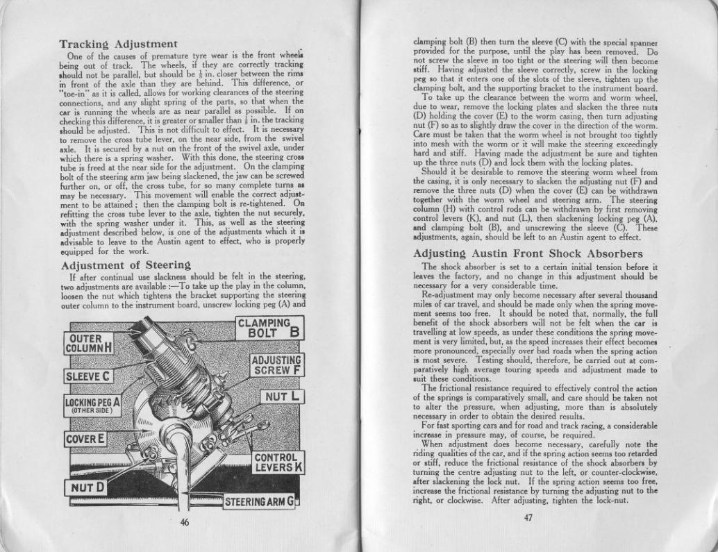
1~
damping bolt (B) then turn the sleeve (C) with the special spannerprovided for the purpose, until the play has been removed. Donot screw the sleeve in too tight or the steering will then become.tiff. Having adjusted the sleeve correctly, screw in the lockingpeg so that it enters one of the slots of the sleeve, tighten up theclamping bolt, and the supporting bracket to the instrument board.
To take up the clearance between the worm and worm wheel,due to wear, remove the locking plates and slacken the three nuts(D) holding the cover (E) to the worm casing, then turn adjustingnut (F) so as to slightly draw the cover in the direction of the worm.Care must be taken that the worm wheel is not brought too tightlyinto mesh with the worm or it will make the steering exceedinglyhard and stiff. Having made the adjustment be sure and tightenup the three nuts (D) and lock them with the locking plates.
Should it be desirable to remove the steering worm wheel fromthe casing, it is only necessary to slacken the adjusting nut (F) andremove the three nuts (D) when the cover (E) can be withdrawntogether with the worm wheel and steering arm. The steeringcolumn (H) with control rods can be withdrawn by first removingcontrol levers (K), and nut (L), then slackening locking peg (A),and clamping bolt (B), and unscrewing the sleeve (C). Theseadjustments, again, should be left to an Austin agent to effect.
Adjusting Austin Front Shock AbsorbersThe shock absorber is set to a certain initial tension before it
leaves the factory, and no change in this adjustment should benecessary for a very considerable time.
Re-adjustment may only become necessary after several thousandmiles of car travel, and should be made only when the spring move-ment seems too free. It should be noted that, normally, the fullbenefit of the shock absorbers will not be felt when the car istravelling at low speeds, as under these conditions the spring move-ment is very limited, but, as the speed increases their effect becomesmore pronounced, especially over bad roads when the spring actionis most severe. Testing should, therefore, be carried out at com-paratively high average touring speeds and adjustment made tosuit these conditions.
The frictional resistance required to effectively control the actionof the springs is comparatively small, and care should be taken notto alter the pressure, when adjusting, more than is absolutelynecessary in order to obtain the desired results.
For fast sporting cars and for road and track racing, a considerableincrease in pressure may, of course, be required.
When adjustment does become necessary, carefully note theriding qualities of the car, and if the spring action seems too retardedor stiff, reduce the frictional resistance of the shock absorbers byturning the centre adjusting nut to the left, or counter-clockwise,after slackening the lock nut. If the spring action seems too free,increase the frictional resistance by turning the adjusting nut to theright, or clockwise. After adjusting, tighten the lock-nut.
Tracking AdjustmentOne of the causes of premature tyre wear is the front whee~
being out of track. The wheels, if they are correctly tracking.hould not be parallel, but should be ! in. closer between the rimsin front of the axle than they are hehind. This difference, or"toe-in" as it is called, allows for working clearances of the steeringconnections, and any slight spring of the parts, so that when thecar is running the wheels are as near parallel as possible. If onchecking this difference, it is greater or smaller than! in. the tracking.hould be adjusted. This is not difficult to effect. It is necessaryto remove the cross tube lever, on the near side, from the swivelaxle. It is secured by a nut on the front of the swivel axle, underwhich there is a spring washer. With this done, the steering crosstube is freed at the near side for the adjustment. On the clampingbolt of the steering arm jaw being slackened, the jaw can be screwedfurther on, or off, the cross tube, for so many complete turns asmay be necessary. This movemenf will enable the correct adju.t-ment to be attained; then the clamping bolt is re-tightened. Onrefitting the cross tube lever to the axle, tighten the nut securely,with the spring washer under it. This, as well as the steeringadjustment described below, is one of the adjustments which it i.advisable to leave to the Austin agent to effect, who is properlyequipped for the work.
Adjustment of SteeringIf after continual use slackness should be felt in the steering,
two adjustments are available ;- To take up the play in the column,loosen the nut which tightens the bracket supporting the steeringouter column to the instrument board, unscrew locking peg (A) and
4647
\1 j
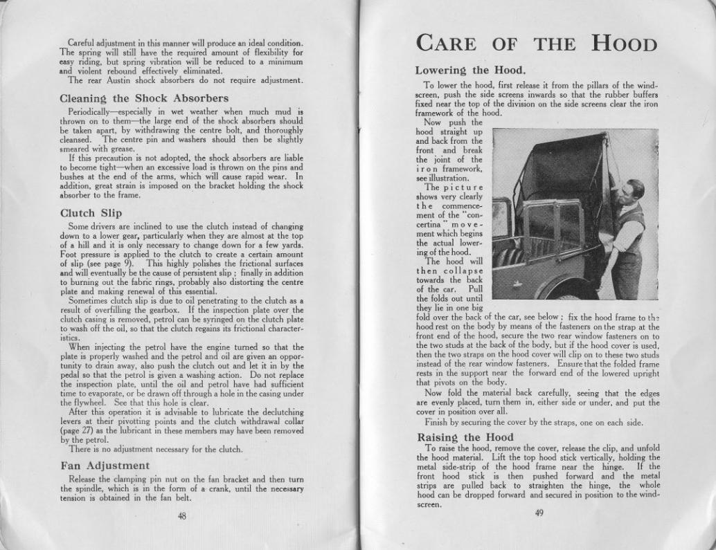
Lowering the Hood.To lower the hood, first release it from the pillars of the wind-
screen, push the side screens inwards so that the rubber buffersfixed near the top of the division on the side screens clear the ironframework of the hood.
Now push thehood straight upand back from thefront and breakthe joint of thei ran framework,see illustration.
The pictureshows very clearlythe commence-ment of the" con-certina" move-ment which beginsthe actual lower-ing of the hood.
The hood willthen collapsetowards the backof the car. Pullthe folds out untilthey lie in one bigfold over the back of the car, see below; fix the hood frame to th,hood rest on the body by means of the fasteners on the strap at thefront end of the hood, secure the two rear window fasteners on tothe two studs at the back of the body, but if the hood cover is used,then the two straps on the hood coverwill clip on to these two studsinstead of the rear window fasteners. Ensure that the folded framerests in the support near the forward end of the lowered uprightthat pivots on the body.
Now fold the material back carefully, seeing that the edgesare evenly placed, turn them in, either side or under, and put thecover in position over all.
Finish by securing the cover by the straps, one on each side.
Careful adjustment in this manner will produce an ideal condition.The spring will still have the required amount of flexibility foreasy riding. but spring vibration will be reduced to a minimumand violent rebound effectively eliminated.
The rear Austin shock absorbers do not require adjustment.
CARE
Cleaning the Shock AbsorbersPeriodically-especially in wet weather when much mud i.
thrown on' to them-the large end of the shock absorbers shouldbe taken apart, by withdrawing the centre bolt, and thoroughlycleansed. The centre pin and washers should then be slightlysmeared with grease.
If this precaution is not adopted, the shock absorbers are liableto become tight-when an excessive load is thrown on the pins andbushes at the end of the arms, which will cause rapid wear. Inaddition, great strain is imposed on the bracket holding the shockabsorber to the frame. .
Clutch SlipSome drivers are inclined to use the clutch instead of changing
down to a lower gear, particularly when they are almost at the topof a hill and it is only necessary to change down for a few yards.Foot pressure is applied to the clutch to create a certain amountof slip (see page 9). This highly polishes the frictional surfacesand will eventually be the cause of persistent slip; finally in additionto burning out the fabric rings, probably also distorting the centreplate and making renewal of this essential.
Sometimes clutch slip is due to oil penetrating to the clutch as aresult of overfilling the gearbox. If the inspection plate over theclutch casing is removed, petrol can be syringed on the clutch plateto wash off the oil, so that the clutch regains its frictional character-istics.
When injecting the petrol have the engine turned so that theplate is properly washed and the petrol and oil are given an oppor-tunity to drain away, also push the clutch out and let it in by thepedal so that the petrol is given a washing action. Do not replacethe inspection plate, until the oil and petrol have had sufficienttime to evaporate, or be drawn off through a hole in the casing underthe flywheel. See that this hole is clear.
After this operation it is advisable to lubricate the declutchinglevers at their pivotting points and the clutch withdrawal collar(page 27) as the lubricant in these members may have been removedby the petrol.
There is no adjustment necessary for the clutch.
~
OF HOODTHE
Raising the HoodTo raise the hood, remove the cover, release the clip, and unfold
the hood material. Lift the top hood stick vertically, holding themetal side-strip of the hood frame near the hinge. If thefront hood stick is then pushed forward and the metalstrips are pulled back to straighten the hinge, the wholehood can be dropped forward and secured in position to the wind-screen.
Fan AdjustmentRelease the clamping pin nut on the fan bracket and then turn
the spindle, which is in the form of a crank, until the necessarytension is obtained in the fan belt.
48
'"
49
j
Care of the Hood CARE of the BODYWORKCare should be taken in folding down the hood to see that the
original folds are used. Should the car have been used in wetweather leave the hood up to dry. Never fold it when wet. FOR the car to look well and keep its beauty and smart appear-
ance, the body must be given ill share of attention; it mustnot be neglected.
The Side Curtains. WashingThe cellulose (or fabric) finish of the car is easily cleaned and
polished. In summer weather when the car is only dusty the dustcan be lightly flicked off without water and there is no risk ofdamaging the finish. When the car is muddy, wash off well withclean running water. Remove any grease or tar splashes withpetrol. Don't use the same sponge and cleaning cloths for thechassis and springs and other greasy parts as are used for the coach-work.
PolishingDry off and then polish with one of the special polishes now
marketed. (Polish is not necessary for the fabric bodies except atinfrequent intervals. Then an ordinary wax polish can be used,only sparingly applied). Such preparations impart a brilliantsurface and preserve and beautify the body. On no account shouldmetal polishes be used, as are sometimes advertised for cellulose.It has been found that the more the surface of the cellulose finish isrubbed by the polishing cloth. the smoother and more lasting is thelustre imparted.
Door locks. hinges and other small working parts should be givena drop or two of oil occasionally.
See the card inserted at end of Handbook for par-ticulars of the proper inflation of pueumatic seats,
The side curtains are secured against movement or rattle byset screws. The pegs at the bottom of the curtains fit into holes inthe aluminium rail on the top of the bodywork, and these pegs arefirmly held by screws. Before the sidescreens can be removed,these screws must be slackened with a coin or screwdriver, and alsothe nut on the inner side of the main hood stick fulcrum.
FLOAT-aN-AIR SEAT INTERIORS.
The essence of comfort with "Float-on-Air" upholstery is lowpressure-to blow up the cushions at all hard is to destroy theirpowers of absorbing vibration. The seat should be quite soft to thetouch, the hand pressed on the surface sinking well in. If the seatsdo not give perfect results release air from the valve as the usual faultis over inflation. The butt ended portion running round the sidesand front of each interior is separately inflated and should be moder-ately well blown up. The centre portion of each interior is alsoseparately inflated, and the pressure should be such that the base ofthe seat can be felt when pressed with the closed fist. This gives theideal pressure and support when sat upon.
To adjust the air pressure open the flap at the rear of the cushion,exposing the valves. The valve at the side inflates the "butt endedportion" above referred to; the other valve (or valves in the rearcushion) inflates the centre section. Draw gently on the tabs till therubber valve protrudes about one inch, do not pull hard otherwisethe valve may be damaged. Roll back the rubber ring towards thecushion when the plug can be readily removed from the tube. Blowwith the mouth or release air as required. Moisten the plug andreinsert as far as it will go, roll ring back until it engages in the de-pression caused by slot in plug. Push hack the valve till the cap isflush with the surface and refasten the flap.
DON'T ,.
~
Don't, please don't-Don't leave the car in gear with the handhrake off.Don't make a fast run with the radiator muff down.Don't fill the radiator with' cold water when the engine is hot.Don't try to turn the engine without first pushing the starting-handle
in to engage fully with the starting nut.Don't be cruel to the starter if the engine will not fire.Don't put an excessive quantity of lubricant in the gear box.Don't pour oil into the engine with the strainer removed.Don't forget the ignition switch when starting up.Don't leave the ignition switched on when the engine is not running.Don't coast with the engine running and the clutch held out.Don't run the engine in a closed garage. (The exhaust gases are
highly toxic and a very small amount in a restricted atmospherewill produce grave, if not fatal, results).
so 51
)
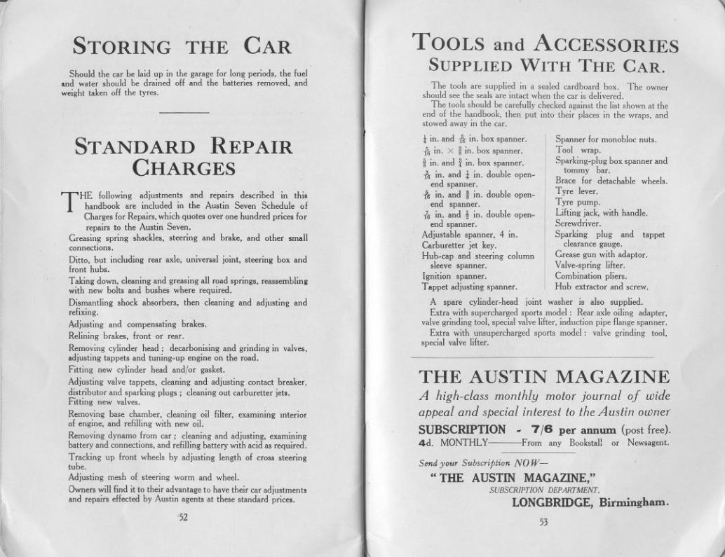
- "
STORING THE CAR TOOLS and ACCESSORIESSUPPLIED WITH THE CAR.
Should the car be laid up in the garage for long periods, the fueland water should be drained off and the batteries removed, andweight taken off the tyres.
The tools are supplied in a sealed cardboard box. The ownershould see the seals are intact when the car is delivered.
The tools should be carefully checked against the list shown at theend of the handbook, then put into their places in the wraps, andstowed away in the car.
i in. and -i'oin. box spanner. Spanner for monobloc nuts.-i'oin. X ! in. box spanner. Tool wrap.
t in. and! in. box spanner. Sparking-plug box spanner and-'- . d l' d bl tommy bar," m. an "m. ou e open-
end spanner, Brace for detachable wheels.-i'o in. and! in, double open- Tyre lever.
end spanner. Tyre pump.f.r in, and t in. double open- Lifting jack, with handle.
end spanner: Screwdriver.Adjustable spanner, 4 in. Sparking plug and tappetCarburetter jet key, clearance gauge.Hub-cap and steering column Grease gun with adaptor.
sleeve spanner. Valve-spring lifter.Ignition spanner. Combination pliers.Tappet adjusting spanner, Hub extractor and screw.
A spare cylinder-head joint washer is also supplied.Extra with supercharged sports model: Rear axle oiling adapter,
valve grinding tool, special valve lifter, induction pipe flange spanner.Extra with unsupercharged sports model: valve grinding tool,
special valve lifter.
STANDARD REPAIRCHARGES
THE following adjustments and repairs described in thishandbook are included in the Austin Seven Schedule ofCharges for Repairs, which quotes over one hundred prices forrepairs to the Austin Seven,
Greasing spring shackles, steering and brake, and other smallconnections.
Ditto, but including rear axle, universal joint, steering box andfront hubs,
Taking down, cleaning and greasing all road springs, reassemblingwith new bolts and bushes where required,
Dismantling shock absorbers, then cleaning and adjusting andrefixing,
Adjusting and compensating brakes,Relining brakes, front or rear.
Removing cylinder head; decarbonising and grinding in valves,adjusting tappets and tuning-up engine on the road,Fitting new cylinder head and/or gasket,
Adjusting valve tappets, cleaning and adjusting contact breaker,distributor and sparking plugs; cleaning out carburetter jets,Fitting new valves.
Removing base chamber, cleaning oil filter, examining mteriorof engine, and refilling with new oil.
Removing dynamo from car; cleaning and adjusting, examiningbattery and connections, and refilling battery with acid as required.
Tracking up front wheels by adjusting length of cross steeringtube.
Adjusting mesh of steering worm and wheel.
Owners will find it to their advantage to have their car adjustmentsand repairs effected by Austin agents at these standard prices,
THE AUSTIN MAGAZINEA high-class monthly motor journal of wideappeal and special interest to the Austin owner
SUBSCRIPTION - 7/6 per annum (post free).4d. MONTHLY From any Bookstall or Newsagent.
'52
Send your SubscriPtion NO W-
"THE AUSTIN MAGAZINE,"SUBSCRIPTION DEPARTMENT,
LONGBRIDGE, Birmingham.
53
~ )
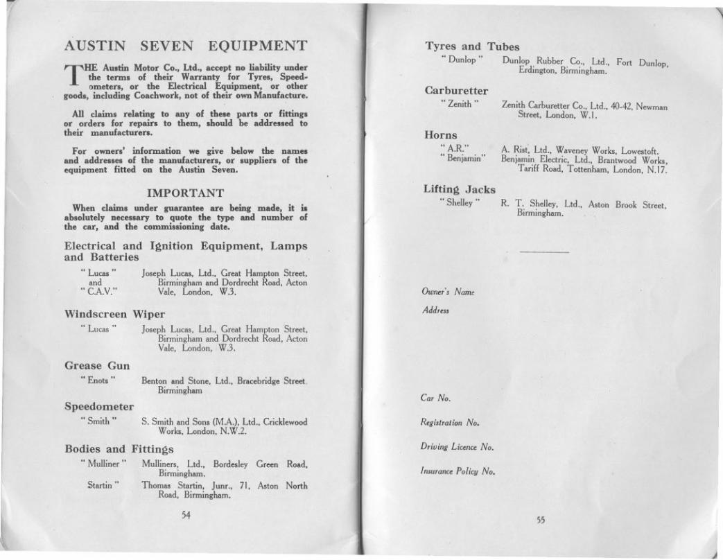
THE AUltin Motor Co., Ltd., accept no liability undertbe tel'Dll of their Warranty for Tyres, Speed.ometero, or the Electrical Equipment. or other
good., including Coachwork, not of their own Manufacture.
All claimo relating to any of these partl or fittinglor ordero for repairl to them, Ihould be addrelled totheir manufacturero.
For ownero' information we give below the nameland addreslel of the manufacturerl, or luppliero of theequipment fitted on the AUltin Seven.
rI
AUSTINr
I
~
""'\
SEVEN EQUIPMENT Tyres and Tubes
" Dunlop " Dunlop Rubber Co.. Ltd., Fort Dunlop,Erdington, Binningbam.
Carburetter"Zenitb" Zenitb Carburetter Co., Ltd., 40-42, Newman
Street. London, W.I.
Horns"A.R."" Benjamin"
A. Ri.t~ Ltd., WaveneyWorks, Lowestoft.Benjamin Electric, Ltd., Brantwood Works,
Tariff Road, Tottenbam, London, N.17.
I
IMPORTANTWhen claimo under guarantee are being made, it io
ablolutely neceloary to quote the type and number ofthe car, and the commillioning date.
Lifting Jacks
" Shelley" R. T. SheHey, Ltd., A.ton Brook Street,Binningham.
Electrical and Ignition Equipment, Lampsand Batteries
" Lucos "and
" C.A.V:'
Jo.eph Lucos, Ltd., Great Hampton Street,Binningham and Dordrecht Road, ActonVale, London, WJ. Own.r', Name
AddressWindscreen Wiper
" Luca. " Jo.eph Luca., Ltd., Great Hampton Street,Birmingham and Dordrecht Road, ActonVale, London, WJ.
Grease Gun"Enot. "
ISpeedometer
"Smith"
Bodies and"Mulliner"
Startin ..
Benton and Stone, Ltd., Bracebridge Street.Binningham
Car No.
S. Smith and Son. (MA), Ltd.. CricklewoodWorks, London, N.W.2.
Registralion No.
FittingsMulliner., Ltd., Bordesley Green Road.
Binningham.Thoma. Startin, Junr.. 71, Aston North
Road, Binningham.
Driving Liunu No.
Insuronu Policy No.
54 55
I
J

r!
"LUCAS" SERVICE DEPOTS\
BELFAST, 3-5, Calvin Street, Mountpottinger.Telegrams: "Servdep," Belfast. Telephone: Belfast 7017.
BIRMINGHAM, Great Hampton Street.Telegrams: "Lucas, Birmingham:' Telephone: Central 8401
(10 lines)BRISTOL, 345, Bath Road.
Telegrams: "Kingly, Bristol:' Telephone: Bristol8400(4 lines)
',1
CARDIFF, 54a, Penarth Road.Telegrams: "Lucas, Cardiff:' Telephone : Cardiff 4603
(4 lines)COVENTRY, Priory Street.
Telegrams: "Lucas, Ccventry:' 'Telephone: Coventry3068and 3841.
11
~r
GLASGOW, 227-229, St. George's Road.Telegrams: "Lucas, Glasgow:' Telephone: Douglas3075
(5 lines)LEEDS, 64, RosevilleRoad.
Telegrams: "Luserdep, Leeds:' Telephone: Leeds 28591(5 lines)
LIVERPOOL, 450-456,Edge Lane,Telegrams: "Luserv, Liverpool." Telephone: Old Swan 1408
(3 lines)LONDON, Dordrecht Road, Acton Vale, W.3,
Telegrams: "Dynomagna, Act, London:'Telephone: Riverside3160(10 lines)
"u
I~
:1
'~,J
DUBLIN, 41, Middle Abbey Street.Tele~rams: "Autolite, Dublin:' Telephone: Dublin 653.
~
. LONDON, 759,High Road, Leyton, E,IO,Telegrams: "Luserdep, Wait, London:'Telephone: Walthamstow 2161 (3 lines).
LONDON. 155,Merton Road, Wandsworth, S.W.18.Telegrams: "Luserv, Wands, London:'Telephone: Putney 5131(4 lines) and 5501.
.
~
I
11
11
MANCHESTER, Talbot Road, Stretford.Telegrams: "Lucas, Stretford:' Telephone: Longford 1101
(5 lines)NEWCASTLE-ON-TYNE, 64-66, St. Mary's Place.
Telegrams: "Motolite, Newcastle-on-Tyne:'Telephone: Central: 3571(3 lines).
56
,\I,
U.
~1\1
:IJ
~