Embed Size (px)
Citation preview
2169-3536 (c) 2016 IEEE. Translations and content mining are permitted for academic research only. Personal use is also permitted, but republication/redistribution requires IEEE permission. Seehttp://www.ieee.org/publications_standards/publications/rights/index.html for more information.
This article has been accepted for publication in a future issue of this journal, but has not been fully edited. Content may change prior to final publication. Citation information: DOI 10.1109/ACCESS.2017.2716344, IEEE Access
i
An Autonomous Wireless Body Area NetworkImplementation Towards IoT Connected Healthcare
ApplicationsTaiyang Wu, Student Member, IEEE, Fan Wu, Student Member, IEEE,
Jean-Michel Redoute, Senior Member, IEEE, and Mehmet Rasit Yuce, Senior Member, IEEE
Abstract—Internet of Things (IoT) is a new technologicalparadigm that can connect things from various fields throughthe Internet. For the IoT connected healthcare applications, thewireless body area network (WBAN) is gaining popularity aswearable devices spring into the market. This paper proposes awearable sensor node with solar energy harvesting and Bluetoothlow energy (BLE) transmission that enables the implementationof an autonomous WBAN. Multiple sensor nodes can be deployedon different positions of the body to measure the subject’s bodytemperature distribution, heartbeat and detect falls. A web-based smartphone application is also developed for displayingthe sensor data and fall notification. To extend the lifetime of thewearable sensor node, a flexible solar energy harvester with anoutput based maximum power point tracking (MPPT) techniqueis used to power the sensor node. Experimental results showthat the wearable sensor node works well when powered by thesolar energy harvester. The autonomous 24 hours operation isachieved with the experimental results. The proposed system withsolar energy harvesting demonstrates that long-term continuousmedical monitoring based on WBAN is possible provided thatthe subject stays outside for a short period of time in a day.
Index Terms—Internet of things, wireless body area network,energy harvesting, maximum power point tracking, bluetooth.
I. INTRODUCTION
INTERNET of Things (IoT) is a new technologicalparadigm that gains attention from vast research fields
in the past few years [1], [2]. In the future healthcare cir-cumstance, the IoT will connect the subjects and the health-care professionals seamlessly [3], [4]. With the advancementof wearable sensors, low-power integrated circuit (IC) andwireless communication technologies, the wireless body areanetwork (WBAN) is becoming an emerging research fieldworldwide [5]. WBAN, also known as body sensor network(BSN), is a wireless network to enable the health moni-toring anywhere anytime around the human body [6], [7].This can be used for the e-health applications, such as thecomputer-assisted rehabilitation, early detection of medicalissues and emergency notification [8]. In recent years, theportable devices, especially smartphones, have almost been anindispensable part of people’s daily life. Therefore, they canbe employed as the gateway between the WBAN and the IoTcloud [9]–[11], as shown in Fig. 1.
Wearable sensors are the key components in the WBANas they collect the vital data of the human body for furtherusage. Researchers from multiple disciplines have presenteddifferent wearable sensor systems for the WBAN applications.
Fig. 1. Wireless body area network with IoT connected healthcare platform
In [12], the authors present a wearable photoplethysmography(PPG) sensor for the heartbeat measurement at the earlobe.Another heartbeat sensor is presented in [13], which is de-signed with the polymer-based flexible strain-gauge sensor. Awearable sensor prototype capable of measuring heart rate,blood oxygen saturation, temperature and humidity during amagnetic resonance imaging (MRI) experiment is presentedin [14]. Seeger et al. propose a middleware solution for thewearable sensor system of WBAN, which is based on thesmartphone applications [15].
Another critical issue in the development of WBAN is thepower consumption in the long-term use of wearable devices.Energy harvesting, especially wearable energy harvesting tech-nology, is a promising solution to enable the long-term oper-ation of WBAN [16]. In [17], the authors present a flexibleenergy harvesting mechanism for ultra-low power wearabledevices. It also studies the performance of a flexible solar panelunder different irradiance levels. Hamid et al. present a novelwearable energy harvester that combines piezoelectric andelectromagnetic energy sources from low frequency vibrationslike human motion [18]. In [19], a wearable bracelet withultra-low power camera and microphone is presented. It ispowered by hybrid solar cells and thermoelectric generators(TEGs), and its self-sustainability is confirmed by simulationsbased on experimental measurements. In [20], an autonomous

2169-3536 (c) 2016 IEEE. Translations and content mining are permitted for academic research only. Personal use is also permitted, but republication/redistribution requires IEEE permission. Seehttp://www.ieee.org/publications_standards/publications/rights/index.html for more information.
This article has been accepted for publication in a future issue of this journal, but has not been fully edited. Content may change prior to final publication. Citation information: DOI 10.1109/ACCESS.2017.2716344, IEEE Access
ii
Fig. 2. Flexible wearable sensor node with energy harvesting
wearable system with energy harvesting module is designed,manufactured and tested for vital signs measurement. Thewearable system powered by a flexible solar panel can beattached to a T-shirt. Another optimal energy harvester usinga flexible photovoltaic module and a maximum power pointtracking (MPPT) technique based on fuzzy logic is proposedin [21]. It is used to power a sensor node with bluetooth lowenergy (BLE) module, which can measure heartbeat and bloodpressure of the subject and send them to a smartphone.
This paper proposes a wearable sensor node with solarenergy harvesting and BLE transmission to implement anautonomous WBAN. The solar energy harvester is controlledby an output based MPPT technique to extract the maximumpower from a flexible solar panel [22]. The sensor node isintegrated with an onboard accelerometer, temperature sensorand a plug-in PPG sensor on a flexible solar panel. Multiplenodes can be deployed on different positions of the body tomeasure the temperature distribution of the body. The node canalso measure the heartbeat and detect the fall of the subject.All the data from the sensor nodes and fall notification willbe transmitted to a web-based smartphone application througha commercial BLE module. When the sensor node is set toan appropriate wake-sleep mode, the 24 hours operation of thesensor node powered by the solar energy harvester is achievedand verified by experiments.
The remainder of the paper is organized as follows: SectionII describes the system architecture. The solar energy harvesterwith the output based MPPT technique is presented in SectionIII. Section IV shows the experimental results of the solarenergy harvester and the wearable sensor node. Lastly, thepaper is concluded with a discussion of future improvementin Section V.
II. SYSTEM ARCHITECTURE
This paper presents the implementation of an autonomousWBAN towards the IoT connected healthcare applications. Itconsists of 3 major parts: 1) a flexible solar energy harvesterwith MPPT; 2) a wearable sensor node with BLE transmission;and 3) a smart phone application acting as the IoT gatewayfor sensor data visualization and emergency notification. Fig.2 shows the overview of the wearable sensor node with solarenergy harvesting.
Fig. 3. Software diagram of the wearable sensor node
A. Flexible solar energy harvester
A flexible solar panel, the MPT3.6-75 from SundanceSolarr (7.2*6.0 cm2), is chosen as the power source for theenergy harvester. Due to its flexibility, it can be easily attachedto the human body for wearable applications. To extract themaximum power from the flexible solar panel, an output basedanalog MPPT circuit is proposed, which will be explained indetail in Section III. The harvested energy from the flexiblesolar panel is stored in a supercapacitor. Here a supercapac-itor is chosen instead of a rechargeable battery. Because asupercapacitor has almost unlimited charging cycles, and itsefficiency of charging and discharging is higher than that ofa battery [23]. An efficient buck-boost voltage regulator, theLTC3130-1 from Linear Technologyr, is adopted to connectthe supercapacitor with the wearable sensor node. The inputrange of the voltage regulator is from 2.4 V to 25 V, and itsoutput voltage is configured at 3.3 V to power the wearablesensor node.
B. Wearable sensor node
The main components of the wearable sensor node includea microcontroller unit (MCU) and 3 sensors for subject datameasurement and processing. The software diagram of thewearable sensor node is illustrated in Fig. 3.
1) MCU: The core of the wearable sensor node is theMCU, which is used to collect and process the sensor data,as well as perform power management to reduce the overallpower consumption. The MCU used in the sensor node is theATmega328P from Atmelr due to its low power, low cost andhigh performance. The CPU speed of the MCU is configuredto 8 MHz at 3.3 V, and it can be throttled down to 1 MHz
2169-3536 (c) 2016 IEEE. Translations and content mining are permitted for academic research only. Personal use is also permitted, but republication/redistribution requires IEEE permission. Seehttp://www.ieee.org/publications_standards/publications/rights/index.html for more information.
This article has been accepted for publication in a future issue of this journal, but has not been fully edited. Content may change prior to final publication. Citation information: DOI 10.1109/ACCESS.2017.2716344, IEEE Access
iii
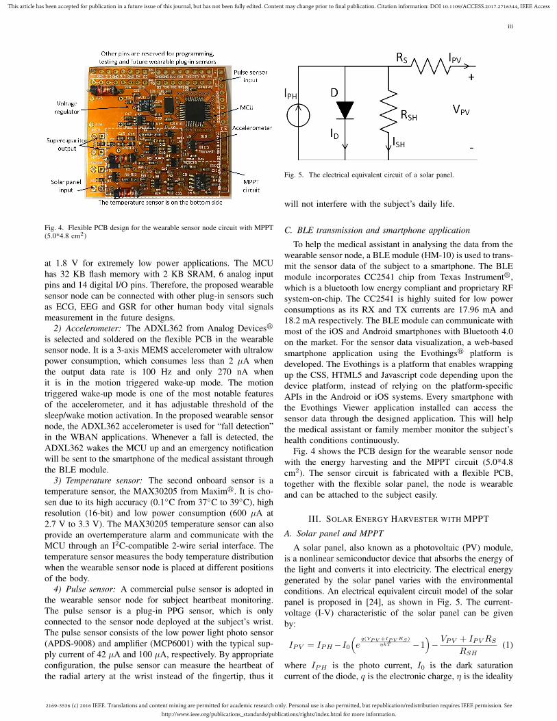
Fig. 4. Flexible PCB design for the wearable sensor node circuit with MPPT(5.0*4.8 cm2)
at 1.8 V for extremely low power applications. The MCUhas 32 KB flash memory with 2 KB SRAM, 6 analog inputpins and 14 digital I/O pins. Therefore, the proposed wearablesensor node can be connected with other plug-in sensors suchas ECG, EEG and GSR for other human body vital signalsmeasurement in the future designs.
2) Accelerometer: The ADXL362 from Analog Devicesr
is selected and soldered on the flexible PCB in the wearablesensor node. It is a 3-axis MEMS accelerometer with ultralowpower consumption, which consumes less than 2 µA whenthe output data rate is 100 Hz and only 270 nA whenit is in the motion triggered wake-up mode. The motiontriggered wake-up mode is one of the most notable featuresof the accelerometer, and it has adjustable threshold of thesleep/wake motion activation. In the proposed wearable sensornode, the ADXL362 accelerometer is used for “fall detection”in the WBAN applications. Whenever a fall is detected, theADXL362 wakes the MCU up and an emergency notificationwill be sent to the smartphone of the medical assistant throughthe BLE module.
3) Temperature sensor: The second onboard sensor is atemperature sensor, the MAX30205 from Maximr. It is cho-sen due to its high accuracy (0.1◦C from 37◦C to 39◦C), highresolution (16-bit) and low power consumption (600 µA at2.7 V to 3.3 V). The MAX30205 temperature sensor can alsoprovide an overtemperature alarm and communicate with theMCU through an I2C-compatible 2-wire serial interface. Thetemperature sensor measures the body temperature distributionwhen the wearable sensor node is placed at different positionsof the body.
4) Pulse sensor: A commercial pulse sensor is adopted inthe wearable sensor node for subject heartbeat monitoring.The pulse sensor is a plug-in PPG sensor, which is onlyconnected to the sensor node deployed at the subject’s wrist.The pulse sensor consists of the low power light photo sensor(APDS-9008) and amplifier (MCP6001) with the typical sup-ply current of 42 µA and 100 µA, respectively. By appropriateconfiguration, the pulse sensor can measure the heartbeat ofthe radial artery at the wrist instead of the fingertip, thus it
Fig. 5. The electrical equivalent circuit of a solar panel.
will not interfere with the subject’s daily life.
C. BLE transmission and smartphone application
To help the medical assistant in analysing the data from thewearable sensor node, a BLE module (HM-10) is used to trans-mit the sensor data of the subject to a smartphone. The BLEmodule incorporates CC2541 chip from Texas Instrumentr,which is a bluetooth low energy compliant and proprietary RFsystem-on-chip. The CC2541 is highly suited for low powerconsumptions as its RX and TX currents are 17.96 mA and18.2 mA respectively. The BLE module can communicate withmost of the iOS and Android smartphones with Bluetooth 4.0on the market. For the sensor data visualization, a web-basedsmartphone application using the Evothingsr platform isdeveloped. The Evothings is a platform that enables wrappingup the CSS, HTML5 and Javascript code depending upon thedevice platform, instead of relying on the platform-specificAPIs in the Android or iOS systems. Every smartphone withthe Evothings Viewer application installed can access thesensor data through the designed application. This will helpthe medical assistant or family member monitor the subject’shealth conditions continuously.
Fig. 4 shows the PCB design for the wearable sensor nodewith the energy harvesting and the MPPT circuit (5.0*4.8cm2). The sensor circuit is fabricated with a flexible PCB,together with the flexible solar panel, the node is wearableand can be attached to the subject easily.
III. SOLAR ENERGY HARVESTER WITH MPPT
A. Solar panel and MPPT
A solar panel, also known as a photovoltaic (PV) module,is a nonlinear semiconductor device that absorbs the energy ofthe light and converts it into electricity. The electrical energygenerated by the solar panel varies with the environmentalconditions. An electrical equivalent circuit model of the solarpanel is proposed in [24], as shown in Fig. 5. The current-voltage (I-V) characteristic of the solar panel can be givenby:
IPV = IPH−I0(eq(VPV +IPV RS)
ηkT −1)− VPV + IPVRS
RSH(1)
where IPH is the photo current, I0 is the dark saturationcurrent of the diode, q is the electronic charge, η is the ideality

2169-3536 (c) 2016 IEEE. Translations and content mining are permitted for academic research only. Personal use is also permitted, but republication/redistribution requires IEEE permission. Seehttp://www.ieee.org/publications_standards/publications/rights/index.html for more information.
This article has been accepted for publication in a future issue of this journal, but has not been fully edited. Content may change prior to final publication. Citation information: DOI 10.1109/ACCESS.2017.2716344, IEEE Access
iv
Fig. 6. I-V and P-V characteristics of a solar panel under different irradiancelevels.
factor of the diode, k is the Boltzmann’s constant and T is thetemperature in Kelvin.
According to (1), the IPV and VPV , as well as the cor-responding power (PPV ) of the solar panel , depend on thelight irradiance level (IPH ) and temperature (T ). Fig. 6 showsthe I-V and P-V characteristics of a solar panel under differentirradiance levels. It can be seen that the solar panel can outputthe maximum power at a certain point, which is called themaximum power point (MPP). However, the MPP moves dueto the variation of the irradiance level and other environmentalconditions. Therefore, to harvest the maximum power from asolar panel, the MPPT circuit is usually adopted within thepower management unit in a solar energy harvesting system.
So far, there have been a lot of studies on the maximumpower point tracking techniques for the application of solarenergy harvesting [25], [26]. One of the most commonly usedMPPT techniques is the perturbation and observation (P&O)[27], which is an iterative method to reach the MPP of a solarpanel. It measures both the voltage and current to calculatethe power of the solar panel and perturbs the operating pointby changing the duty cycle of the DC-DC converter usedin the solar energy harvester periodically. If the power fromthe solar panel increases, the P&O will keep the changeof the duty cycle in the same direction; otherwise, it willchange the duty cycle in the opposite direction. Eventually theduty cycle will oscillate around a value corresponding to theMPP, where the solar panel can output the maximum power.The implementation of the P&O technique is complex as itneeds both the voltage and current to calculate the power[28]. Another common MPPT technique is the fractionalopen circuit voltage (FOCV) technique [29], which assumesthe voltage at the MPP is proportional to the open circuitvoltage of the solar panel. It simplifies the implementationof the MPPT circuit as only the voltage is required for themeasurement. The limitation of FOCV is that the proportionof the voltage at the MPP to the open circuit voltage is basedon the experimental observation. The proportion varies withthe irradiance level and temperature, which means the trackingof MPP is not always precise. There are also other MPPT
Fig. 7. Block diagram of the flexible solar energy harvester.
techniques, like the incremental conductance (IC), short circuitcurrent (SCC) and temperature based MPPT technique [25].With the improvement of microcontroller processing power,researchers have proposed more intelligent MPPT techniques,like the fuzzy logic control (FLC) and the neural networktechnique [26].
B. Proposed output based MPPT technique
In this work, the wearable sensor node is powered by aflexible solar energy harvester, whose block diagram is shownin Fig. 7. The flexible solar panel and the load is connected bya buck-boost converter, consisting of L1, L2, C1 and M1. Toharvest the maximum power from the solar panel, an outputbased MPPT technique is proposed to control the duty cycle(D) of the buck-boost converter for impedance matching [30].
For the buck-boost converter, the relationship of the input(VPV & IPV ) and output (VOUT & IOUT ) can be expressedas:
VPV =1−D
DVOUT (2)
andIPV =
D
1−DIOUT (3)
Thus the equivalent resistance of the output load seen fromthe input side of the buck-boost converter is:
Req =(1−D)2
D2Rload (4)
From the I-V characteristic of the solar panel in Fig. 6, thereexists a resistance (RMPP = VMPP /IMPP ) corresponding tothe MPP. This means the solar panel can output the maximumpower when the load resistance equals RMPP . By changingthe D in (4), the equivalent resistance Req can be matched tothe RMPP , therefore the MPP of the solar panel is reached.
To measure the power of the solar panel, conventionalMPPT techniques (like P&O) multiply the VPV and IPV atthe input side of the DC-DC converter. The proposed MPPTtechnique focuses on the output side and only needs oneparameter. For a constant resistive load (Rload) at the outputside, the output power is:
POUT = I2OUTRload (5)
Considering the efficiency η of the buck-boost converter, theinput power from the solar panel is:
PPV =I2OUTRload
η(6)
2169-3536 (c) 2016 IEEE. Translations and content mining are permitted for academic research only. Personal use is also permitted, but republication/redistribution requires IEEE permission. Seehttp://www.ieee.org/publications_standards/publications/rights/index.html for more information.
This article has been accepted for publication in a future issue of this journal, but has not been fully edited. Content may change prior to final publication. Citation information: DOI 10.1109/ACCESS.2017.2716344, IEEE Access
v
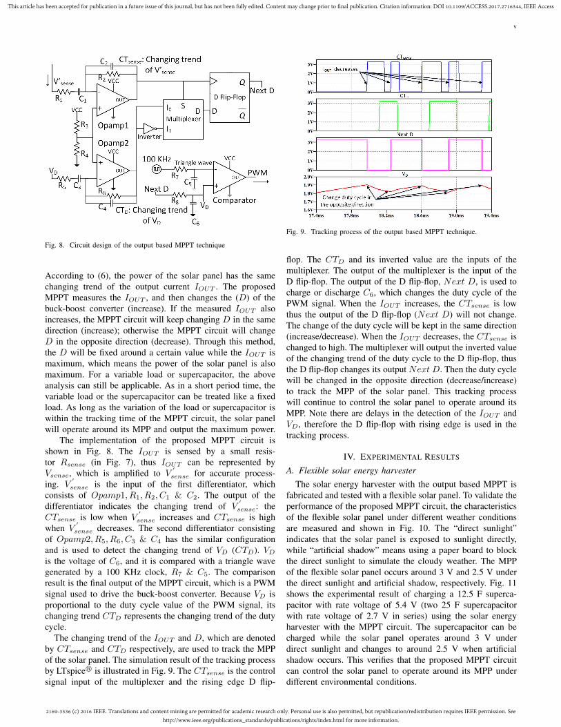
Fig. 8. Circuit design of the output based MPPT technique
According to (6), the power of the solar panel has the samechanging trend of the output current IOUT . The proposedMPPT measures the IOUT , and then changes the (D) of thebuck-boost converter (increase). If the measured IOUT alsoincreases, the MPPT circuit will keep changing D in the samedirection (increase); otherwise the MPPT circuit will changeD in the opposite direction (decrease). Through this method,the D will be fixed around a certain value while the IOUT ismaximum, which means the power of the solar panel is alsomaximum. For a variable load or supercapacitor, the aboveanalysis can still be applicable. As in a short period time, thevariable load or the supercapacitor can be treated like a fixedload. As long as the variation of the load or supercapacitor iswithin the tracking time of the MPPT circuit, the solar panelwill operate around its MPP and output the maximum power.
The implementation of the proposed MPPT circuit isshown in Fig. 8. The IOUT is sensed by a small resis-tor Rsense (in Fig. 7), thus IOUT can be represented byVsense, which is amplified to V
′
sense for accurate process-ing. V
′
sense is the input of the first differentiator, whichconsists of Opamp1, R1, R2, C1 & C2. The output of thedifferentiator indicates the changing trend of V
′
sense: theCTsense is low when V
′
sense increases and CTsense is highwhen V
′
sense decreases. The second differentiator consistingof Opamp2, R5, R6, C3 & C4 has the similar configurationand is used to detect the changing trend of VD (CTD). VDis the voltage of C6, and it is compared with a triangle wavegenerated by a 100 KHz clock, R7 & C5. The comparisonresult is the final output of the MPPT circuit, which is a PWMsignal used to drive the buck-boost converter. Because VD isproportional to the duty cycle value of the PWM signal, itschanging trend CTD represents the changing trend of the dutycycle.
The changing trend of the IOUT and D, which are denotedby CTsense and CTD respectively, are used to track the MPPof the solar panel. The simulation result of the tracking processby LTspicer is illustrated in Fig. 9. The CTsense is the controlsignal input of the multiplexer and the rising edge D flip-
Fig. 9. Tracking process of the output based MPPT technique.
flop. The CTD and its inverted value are the inputs of themultiplexer. The output of the multiplexer is the input of theD flip-flop. The output of the D flip-flop, Next D, is used tocharge or discharge C6, which changes the duty cycle of thePWM signal. When the IOUT increases, the CTsense is lowthus the output of the D flip-flop (Next D) will not change.The change of the duty cycle will be kept in the same direction(increase/decrease). When the IOUT decreases, the CTsense ischanged to high. The multiplexer will output the inverted valueof the changing trend of the duty cycle to the D flip-flop, thusthe D flip-flop changes its output Next D. Then the duty cyclewill be changed in the opposite direction (decrease/increase)to track the MPP of the solar panel. This tracking processwill continue to control the solar panel to operate around itsMPP. Note there are delays in the detection of the IOUT andVD, therefore the D flip-flop with rising edge is used in thetracking process.
IV. EXPERIMENTAL RESULTS
A. Flexible solar energy harvester
The solar energy harvester with the output based MPPT isfabricated and tested with a flexible solar panel. To validate theperformance of the proposed MPPT circuit, the characteristicsof the flexible solar panel under different weather conditionsare measured and shown in Fig. 10. The “direct sunlight”indicates that the solar panel is exposed to sunlight directly,while “artificial shadow” means using a paper board to blockthe direct sunlight to simulate the cloudy weather. The MPPof the flexible solar panel occurs around 3 V and 2.5 V underthe direct sunlight and artificial shadow, respectively. Fig. 11shows the experimental result of charging a 12.5 F superca-pacitor with rate voltage of 5.4 V (two 25 F supercapacitorwith rate voltage of 2.7 V in series) using the solar energyharvester with the MPPT circuit. The supercapacitor can becharged while the solar panel operates around 3 V underdirect sunlight and changes to around 2.5 V when artificialshadow occurs. This verifies that the proposed MPPT circuitcan control the solar panel to operate around its MPP underdifferent environmental conditions.

2169-3536 (c) 2016 IEEE. Translations and content mining are permitted for academic research only. Personal use is also permitted, but republication/redistribution requires IEEE permission. Seehttp://www.ieee.org/publications_standards/publications/rights/index.html for more information.
This article has been accepted for publication in a future issue of this journal, but has not been fully edited. Content may change prior to final publication. Citation information: DOI 10.1109/ACCESS.2017.2716344, IEEE Access
vi
Fig. 10. I-V (a) and P-V (b) characteristics of the flexible solar panel underthe experimental condition
Fig. 11. Performance of the solar energy harvester with MPPT circuit
The solar energy harvester consists of a flexible solar panel,a buck-boost converter, the MPPT circuit and a supercapacitorfor energy storage. Table I shows the charging performanceof the solar energy harvester under different conditions. Asthe supercapacitors in series have a rate voltage of 5.4 Vand the lowest input of the voltage regulator is 2.4 V, thecharging time in Table I refers to the time of charging thesupercapacitor from 2.4 V to 5.4 V with the proposed solarenergy harvester. Experimental results show that the solarenergy harvester needs about 30, 60 and 120 min to chargethe 12.5 F supercapacitor from 2.4 V to 5.4 V on sunny,partially cloudy and cloudy weather conditions, respectively.In practice, the supercapacitor is charged to 5 V (belowthe rate voltage) to ensure the long-term behaviour of thesupercapacitor.
TABLE ITIME OF CHARGING A 12.5 F SUPERCAPACITOR FROM 2.4 V TO 5.4 V
Weather condition Charging time (min)Test1 Test2 Test3
Sunny 25 23 28Partially cloudy 58 62 65
Cloudy 122 130 115
(a) (b)
(c)
Fig. 12. The wearable sensor node with solar energy harvesting: (a) frontside; (b) back side; (c) experimental setup.
B. Wearable sensor node
Fig. 12 shows the complete setup of the wearable sensornode with the solar energy harvester. Fig. 12(a) illustrates thefront side of wearable sensor node, which is the flexible solarpanel. The back side consists of the sensor node circuit and theBLE module, which is shown in Fig. 12(b). In the experiment,two wearable sensor nodes are worn by the subject. SensorNode 1 is on the wrist for the heartbeat and wrist temperaturemeasurement, while Sensor Node 2 is placed on the chestfor the body temperature measurement and fall detection, asshown in Fig. 12(c). The data collected from both wearablesensor nodes are transmitted to a smartphone (Fig. 13), whichwill be monitored by the subject or a healthcare professional.Fig. 13(b) illustrates an example of the realtime plot of theheartbeat and temperature when the subject rides a stationarybicycle for exercise.

2169-3536 (c) 2016 IEEE. Translations and content mining are permitted for academic research only. Personal use is also permitted, but republication/redistribution requires IEEE permission. Seehttp://www.ieee.org/publications_standards/publications/rights/index.html for more information.
This article has been accepted for publication in a future issue of this journal, but has not been fully edited. Content may change prior to final publication. Citation information: DOI 10.1109/ACCESS.2017.2716344, IEEE Access
vii
(a) (b)
Fig. 13. The smartphone application for the wearable sensor node: (a) Sensordata from two nodes; (b) The realtime plot of heartbeat and temperature ofthe wrist node when riding a stationary bicycle.
C. Energy consumption
Low-power consumption is a critical issue in the applicationof wearable devices as they usually aim for long-term opera-tion. To extend the lifetime of the proposed wearable sensornode, it can be set to sleep mode to save energy when thereis no need for a measurement. Fig. 14 illustrates the currentconsumption of the proposed wearable sensor node during onecycle in the wake-sleep mode. The explicit average currentsof the sensor node at different operation stages are presentedin Table II. The operation voltage of the sensor node (Vnode)is 3.3 V, therefore the average active and sleep energy of thenode in one cycle can be calculated as:
Eactive = Vnode × (I1 × t1 + I2 × t2 + I3 × t3 + I4 × t4) (7)
andEsleep = Vnode × I5 × t5 (8)
In the experiment the wearable sensor node is set to measurethe subject’s data every 10 min, which is 14.5 s active modeand 584.5 s sleep mode respectively. Under the experimentalconfiguration the Eactive is 667.8 mJ and the Esleep is 385.8mJ, thus the average energy consumption of the wearablesensor node Enode is 1053.6 mJ in one 10 min cycle. Thecorresponding power consumption Pnode under this operationmode is 1.76 mW (1053.6/600).
D. 24 hours operation of the wearable sensor node
To further extend the lifetime of the wearable sensor nodeor even enable the autonomous 24 hours operation, the solarenergy harvester is used to power the sensor node. Theenergy storage component used is the 12.5 F supercapacitormentioned previously. Within the normal operation voltagefrom 2.4 V (lowest input of the voltage regulator) to 5.0 V
TABLE IITHE CURRENT OF THE SENSOR NODE AT DIFFERENT OPERATION STAGES
Stage Mode Current (mA) Time (s)1 MCU (I1) 4.3 0.5 (t1)
2MCU+PPG+
Temperature (I2) 5.0 1 (t2)
3MCU+BLE+PPG+Temperature (I3) 14.3 13.5 (t3)
4 MCU (I4) 4.3 0.5 (t4)5 Sleep (I5) 0.2 584.5 (t5)
Fig. 14. Current consumption of the sensor node at different operation stages.
(below the supercapacitor’s rate voltage), the maximum energystored in the supercapacitor is:
Estore =1
2× C × (V 2
max − V 2min)
=1
2× 12.5× (5.02 − 2.42)
= 120.25 J
(9)
When the operation cycle of wearable sensor node is set to10 min, the average energy consumption of the node Enode is1053.6 mJ. The supercapacitor powers the sensor node througha voltage regulator (LTC3130-1), which has a typical efficiency(ηreg) of 90% at 3.3 V. By calculation, the fully chargedsupercapacitor can power the wearable sensor node for:
N = ηreg × Enode/Enode
= 90%× 120.25/1.0536 ≈ 102 cycles(10)
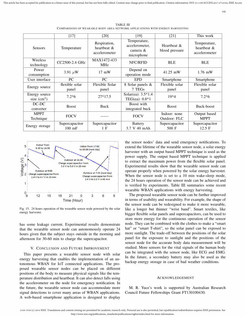
Therefore the wearable sensor node can be powered by thesupercapacitor for 17 hours (102/6) theoretically, which issufficient for the operation at night. Fig. 15 illustrates thevoltage of the supercapacitor in 24 hours. The experimentwas done on a sunny day, and the sunrise and sunset timeon the experiment date (04/04/2017) is 06:30 am and 18:00pm respectively. The longest operation time of the sensor nodeachieved is 15 hours (from 17:00 pm to 08:00 am next day).It is less than the theoretical calculation as the supercapacitor
2169-3536 (c) 2016 IEEE. Translations and content mining are permitted for academic research only. Personal use is also permitted, but republication/redistribution requires IEEE permission. Seehttp://www.ieee.org/publications_standards/publications/rights/index.html for more information.
This article has been accepted for publication in a future issue of this journal, but has not been fully edited. Content may change prior to final publication. Citation information: DOI 10.1109/ACCESS.2017.2716344, IEEE Access
viii
TABLE IIICOMPARISONS OF WEARABLE BODY AREA NETWORK APPLICATIONS WITH ENERGY HARVESTING
[17] [20] [19] [21] This work
Sensors TemperatureRespiration,heartbeat &
accelerometer
Temperature,accelerometer,
camera µphone
Heartbeat &blood pressure
Temperature,heartbeat &
accelerometer
Wirelesstechnology CC2500-2.4 GHz MAX1472-433
MHz NFC/RFID BLE BLE
Powerconsumption 3.91 µW 17 mW Depend on
operation mode 41.25 mW 1.76 mW
User interface PC PC EPD Smartphone Smartphone
Energy source flexible solarpanel
Flexible Solarpanel
8 Solar panels &7 TEGs
Flexible solarpanel
Flexible solarpanel
Energy sourcesize (cm2) 7.2*6 27*17.5 Solar(ea): 3.5*1.4
TEG(ea): 0.8*1 19*4 7.2*6
DC-DCconverter Boost Buck Boost with
integrated buck Boost Buck-boost
MPPTTechnique FOCV —— FOCV Indoor: none
Outdoor: FLCOutput based
MPPT
Energy storage Supercapacitor Supercapacitor Battery Supercapacitor Supercapacitor100 mF 1 F 3.7 V 40 mAh 500 F 12.5 F
Fig. 15. 24 hours operation of the wearable sensor node powered by the solarenergy harvester.
has some leakage current. Experimental results demonstratethat the wearable sensor node can autonomously operate 24hours given that the subject stays outside in the morning andafternoon for 30-60 min to charge the supercapacitor.
V. CONCLUSION AND FUTURE IMPROVEMENT
This paper presents a wearable sensor node with solarenergy harvesting that enables the implementation of an au-tonomous WBAN for IoT connected applications. The pro-posed wearable sensor nodes can be placed on differentpositions of the body to measure physical signals like the tem-perature distribution and heartbeat. It can also detect falls usingthe accelerometer on the node for emergency notification. Inthe future, the wearable sensor node can accommodate moresignal detections to cover many areas of WBAN applications.A web-based smartphone application is designed to display
the sensor nodes’ data and send emergency notifications. Toextend the lifetime of the wearable sensor node, a solar energyharvester with an output based MPPT technique is used as thepower supply. The output based MPPT technique is appliedto extract the maximum power from the flexible solar panel.Experimental results show that the wearable sensor node canoperate properly when powered by the solar energy harvester.When the sensor node is set to a 10 min wake-sleep mode,the 24 hours operation of the sensor node can be achieved andis verified by experiments. Table III summaries some recentwearable WBAN applications with energy harvesting.
The proposed wearable sensor node can be further improvedin terms of usability and wearability. For example, the shape ofthe sensor node can be redesigned to make it more wearable,like a longer but thinner “wrist band”. Smart textiles, likebigger flexible solar panels and supercapacitors, can be used tostore more energy for the continuous operation of the sensornode. They can be combined with the clothes to make a “smarthat” or “smart T-shirt”, so the solar panel can be exposed tomore sunlight. The trade-off between the positions of the solarpanel for the exposure to sunlight and the positions of thesensor node for the accurate body data measurement will bestudied. More sensors for the vital signals of the human bodycan be integrated with the sensor node, like ECG and EMG.In the future, a secondary battery may also be used as thebackup energy storage in case of bad weather conditions.
ACKNOWLEDGEMENT
M. R. Yuce’s work is supported by Australian ResearchCouncil Future Fellowships Grant FT130100430.

2169-3536 (c) 2016 IEEE. Translations and content mining are permitted for academic research only. Personal use is also permitted, but republication/redistribution requires IEEE permission. Seehttp://www.ieee.org/publications_standards/publications/rights/index.html for more information.
This article has been accepted for publication in a future issue of this journal, but has not been fully edited. Content may change prior to final publication. Citation information: DOI 10.1109/ACCESS.2017.2716344, IEEE Access
ix
REFERENCES
[1] G. Fortino and P. Trunfio, “Internet of things based on smart objects:technology, middleware and applications,” Cham, Switzerland: Springer,2014.
[2] I. Lee and K. Lee, “The internet of things (iot): Applications, invest-ments, and challenges for enterprises,” Business Horizons, vol. 58, no. 4,pp. 431–440, 2015.
[3] F. Cicirelli, G. Fortino, A. Giordano, A. Guerrieri, G. Spezzano, andA. Vinci, “On the design of smart homes: A framework for activityrecognition in home environment,” Journal of medical systems, vol. 40,no. 9, pp. 1–17, 2016.
[4] P. Gope and T. Hwang, “Bsn-care: a secure iot-based modern healthcaresystem using body sensor network,” IEEE Sensors Journal, vol. 16,no. 5, pp. 1368–1376, 2016.
[5] E. Jovanov and A. Milenkovic, “Body area networks for ubiquitoushealthcare applications: opportunities and challenges,” Journal of med-ical systems, vol. 35, no. 5, pp. 1245–1254, 2011.
[6] R. Gravina, P. Alinia, H. Ghasemzadeh, and G. Fortino, “Multi-sensorfusion in body sensor networks: State-of-the-art and research chal-lenges,” Information Fusion, vol. 35, pp. 68–80, 2017.
[7] C. C. Poon, B. P. Lo, M. R. Yuce, A. Alomainy, and Y. Hao, “Bodysensor networks: In the era of big data and beyond,” IEEE reviews inbiomedical engineering, vol. 8, pp. 4–16, 2015.
[8] M. R. Yuce, “Implementation of wireless body area networks forhealthcare systems,” Sensors and Actuators A: Physical, vol. 162, no. 1,pp. 116–129, 2010.
[9] G. Fortino, G. Di Fatta, M. Pathan, and A. V. Vasilakos, “Cloud-assistedbody area networks: state-of-the-art and future challenges,” WirelessNetworks, vol. 20, no. 7, pp. 1925–1938, 2014.
[10] G. Aloi, G. Caliciuri, G. Fortino, R. Gravina, P. Pace, W. Russo,and C. Savaglio, “Enabling iot interoperability through opportunisticsmartphone-based mobile gateways,” Journal of Network and ComputerApplications, vol. 81, pp. 74–84, 2017.
[11] M. M. Hassan, K. Lin, X. Yue, and J. Wan, “A multimedia healthcaredata sharing approach through cloud-based body area network,” FutureGeneration Computer Systems, vol. 66, pp. 48–58, 2017.
[12] K. Sonoda, Y. Kishida, T. Tanaka, K. Kanda, T. Fujita, K. Higuchi,and K. Maenaka, “Wearable photoplethysmographic sensor system withpsoc microcontroller,” International Journal of Intelligent Computing inMedical Sciences & Image Processing, vol. 5, no. 1, pp. 45–55, 2013.
[13] Y. H. Kwak, W. Kim, K. B. Park, K. Kim, and S. Seo, “Flexible heartbeatsensor for wearable device,” Biosensors and Bioelectronics, vol. 94, pp.250–255, 2017.
[14] C. Vogt, J. Reber, D. Waltisberg, L. Buthe, J. Marjanovic,N. Munzenrieder, K. P. Pruessmann, and G. Troster, “A wearable blue-tooth le sensor for patient monitoring during mri scans,” in 38th Annu.Int. Conf. of Engineering in Medicine and Biology Society (EMBC),USA, 2016, pp. 4975–4978.
[15] C. Seeger, K. Van Laerhoven, and A. Buchmann, “Myhealthassistant:An event-driven middleware for multiple medical applications on asmartphone-mediated body sensor network,” IEEE journal of biomedicaland health informatics, vol. 19, no. 2, pp. 752–760, 2015.
[16] T. J. Voss, V. Subbian, and F. R. Beyette, “Feasibility of energyharvesting techniques for wearable medical devices,” in 36th Annu.Int. Conf. of the IEEE Engineering in Medicine and Biology Society(EMBC), Chicago, USA, 2014, pp. 626–629.
[17] W. Y. Toh, Y. K. Tan, W. S. Koh, and L. Siek, “Autonomous wearablesensor nodes with flexible energy harvesting,” IEEE sensors journal,vol. 14, no. 7, pp. 2299–2306, 2014.
[18] R. Hamid and M. R. Yuce, “A wearable energy harvester unit usingpiezoelectric–electromagnetic hybrid technique,” Sensors and ActuatorsA: Physical, vol. 257, pp. 198–207, 2017.
[19] M. Magno, D. Brunelli, L. Sigrist, R. Andri, L. Cavigelli, A. Gomez, andL. Benini, “Infinitime: Multi-sensor wearable bracelet with human bodyharvesting,” Sustainable Computing: Informatics and Systems, vol. 11,pp. 38–49, 2016.
[20] A. Dionisi, D. Marioli, E. Sardini, and M. Serpelloni, “Autonomouswearable system for vital signs measurement with energy-harvestingmodule,” IEEE Transactions on Instrumentation and Measurement,vol. 65, no. 6, pp. 1423–1434, 2016.
[21] T. V. Tran and W.-Y. Chung, “High-efficient energy harvester withflexible solar panel for a wearable sensor device,” IEEE Sensors Journal,vol. 16, no. 24, pp. 9021–9028, 2016.
[22] T. Wu, M. S. Arefin, J.-M. Redoute, and M. R. Yuce, “A solar energyharvester with an improved mppt circuit for wearable iot,” in 11th EAI
Int. Conf. on Body Area Networks (Bodynets), Turin, Italy, 2016, pp.166–170.
[23] F. Wu, C. Rudiger, and M. R. Yuce, “Real-time performance of a self-powered environmental iot sensor network system,” Sensors, vol. 17,no. 2, pp. 1–14, 2017.
[24] D. Sera, R. Teodorescu, and P. Rodriguez, “Pv panel model based ondatasheet values,” in IEEE Int. Symp. on Industrial Electronics (ISIE),2007, pp. 2392–2396.
[25] P. Bhatnagar and R. Nema, “Maximum power point tracking controltechniques: State-of-the-art in photovoltaic applications,” Renewable andSustainable Energy Reviews, vol. 23, pp. 224–241, 2013.
[26] S. E. Babaa, M. Armstrong, and V. Pickert, “Overview of maximumpower point tracking control methods for pv systems,” Journal of Powerand Energy Engineering, vol. 2014, 2014.
[27] N. Femia, G. Petrone, G. Spagnuolo, and M. Vitelli, “A techniquefor improving p&o mppt performances of double-stage grid-connectedphotovoltaic systems,” IEEE Transactions on Industrial Electronics,vol. 56, no. 11, pp. 4473–4482, 2009.
[28] Y. Wang, Y. Liu, C. Wang, Z. Li, X. Sheng, H. G. Lee, N. Chang, andH. Yang, “Storage-less and converter-less photovoltaic energy harvestingwith maximum power point tracking for internet of things,” IEEETransactions on Computer-Aided Design of Integrated Circuits andSystems, vol. 35, no. 2, pp. 173–186, 2016.
[29] A. Frezzetti, S. Manfredi, and A. Suardi, “Adaptive focv-based controlscheme to improve the mpp tracking performance: an experimentalvalidation,” IFAC Proceedings Volumes, vol. 47, no. 3, pp. 4967–4971,2014.
[30] T. Wu, M. S. Arefin, D. Shmilovitz, J.-M. Redoute, and M. R. Yuce,“A flexible and wearable energy harvester with an efficient and fast-converging analog mppt,” in 12th Biomedical Circuits and Systems Conf.(BioCAS), Shanghai, China, 2016, pp. 336–339.
Taiyang Wu received his B.E. degree from South-east University, Nanjing, China in 2014. He is cur-rently pursuing his Ph.D. degree in Electrical andComputer Systems Engineering in Monash Univer-sity. His main areas of research interest are energyharvesting, wireless sensor network and IoT con-nected applications.
Fan Wu received his B.E. degree from MonashUniversity in 2015. He is currently doing his Ph.D.degree in Electrical and Computer Systems Engi-neering in Monash University. He was a researchassistant with the Engineering Department from July2015 to Feb. 2017. His main areas of research inter-est are wireless sensor network, energy harvestingand IoT innovations.
Jean-Michel Redoute received the degree of M. S.in electronics at the University College of Antwerp,Belgium, in 1998, and the degree of M. Eng. inelectrical engineering at the University of Brus-sels, Belgium, in 2001. In August 2001, he startedworking at Alcatel Bell in Antwerp, where he wasinvolved in the design of analog microelectroniccircuits for telecommunications systems. In January2005, he joined the ESAT-MICAS laboratories of theUniversity of Leuven as a Ph. D. research assistant.In May 2009, he obtained his Ph. D. entitled ”Design
of EMI resisting analog integrated circuits”. In September 2009, he startedworking at the Berkeley Wireless Research Center at the University ofCalifornia, at Berkeley as a postdoctoral scholar. In September 2010, he joinedMonash University as a senior lecturer. His research interests include mixed-signal integrated circuit (IC) design, electromagnetic compatibility (EMC),biomedical (integrated and non-integrated) circuit design and radio-frequencyintegrated circuit design.
2169-3536 (c) 2016 IEEE. Translations and content mining are permitted for academic research only. Personal use is also permitted, but republication/redistribution requires IEEE permission. Seehttp://www.ieee.org/publications_standards/publications/rights/index.html for more information.
This article has been accepted for publication in a future issue of this journal, but has not been fully edited. Content may change prior to final publication. Citation information: DOI 10.1109/ACCESS.2017.2716344, IEEE Access
x
Mehmet Yuce is an associate professor in the De-partment of Electrical and Computer Systems Engi-neering, Monash University, Australia. He receivedthe M.S. degree in Electrical and Computer Engi-neering from the University of Florida, Gainesville,Florida in 2001, and the Ph.D. degree in Electricaland Computer Engineering from North CarolinaState University (NCSU), Raleigh, NC in December2004. He was a post-doctoral researcher in theElectrical Engineering Department at the Universityof California at Santa Cruz in 2005. He was an
academic member in the School of Electrical Engineering and ComputerScience, University of Newcastle, New South Wales, Australia until Jul 2011.In July 2011, he joined Monash University.
His research interests include wearable devices, Internet-of-Things (IoT)for healthcare, wireless implantable telemetry, wireless body area network(WBAN), bio-sensors, integrated circuit technology dealing with digital,analog and radio frequency circuit designs for wireless, biomedical, and RFapplications. Dr. Yuce has published more than 150 technical articles in theabove areas and received a NASA group achievement award in 2007 fordeveloping an SOI transceiver. He received a best journal paper award in2014 from the IEEE Microwave Theory and Techniques Society (MTTS). Hereceived a research excellence award in the Faculty of Engineering and BuiltEnvironment, University of Newcastle in 2010. He is an author of the books:Wireless Body Area Networks published in 2011 and Ultra-Wideband and 60GHz Communications for Biomedical Applications published in 2013. He isa senior member of IEEE. He is a topical editor for IEEE Sensors Journaland a guest editor for IEEE Journal of Biomedical and Health Informatics in2015.