Embed Size (px)
Citation preview


I 0 £ m läS •I S g IIIM
5 US IIP I.I
1.25 1.4
1.8
1.6
MICROCOPY RESOLUTION TEST CHART
NATIONAL SUftCAU Of STANDARDS - i>63 - A

w Research and Development Technical Report DELET-TR-79-0272-F
II
VIBRATION RESISTANT QUARTZ CRYSTAL RESONATORS
1 I I I I I
^
i> (St <M CO r-4
<c B. Goldfrank a A. Warner
Q-.
C.3
FREQUENCY ELECTRONICS, INC. 55 Charles Lindbergh Blvd. Mitchel Field, NY 11553
November 1982 Final Report for period 28 Oct 79 - 28 Feb 82
DISTRIBUTION STMIMENT
Approved lor public rtltis<:
fliitnouiion unlimited.
3
Prepared for: ELECTRONICS TECHNOLOGY 6 DEVICES LABORATORY
ki.
aERADCOM **• US ARMY ELECTRONICS RESEARCH AND DEVELOPMENT COMMAND g FORT MONMOUTH, NEW JERSEY 07703
83 09 08 039

r^ T
NOTICES
Disclaimers
The citation of trade names and name« of manufacturers in this report it not to be construed as official Government indorsement or approval of commercial products or services referenced herein.
Disposition
Destroy this report when it is no loafer seeded. Do not return it to the originator.
-
I I

I I I
I
!
I
UNCLASSIFIED SECURITY CLASSIFICATION OF THIS PAGE C*nan Data tntatad)
REPORT DOCUMENTATION PAGE I REPORT NUMBER
DELET-TR-79-0272-F 2 OOVT ACCESSION NO
&LAJ22. S RECIPIENT'S CAT ALOG NUMBER
4 TITLE (and Submit)
Vibration Resistant Quartz Crystal Resonators
7. AtlTMOR'j)
B. Goldfrank A. Warner
». PERFORMING ORGANIZATION NAME AND ADDRESS
Frequency Electronics, Inc. 55 Charles Lindbergh Blvd. Mitchel Field, NY 11553
II. CONTROLLING OFFICE NAME AND ADDRESS
U.S. Army Electronics Technology and Devices Laboratory
Attn: DELET-MQ if QJoWjP.Pg'g&EcVNAW A23&3i(n mSSSi 55 55S555 iliüT,
READ INSTRUCTIONS BEFORE COMPLETING FORM
S. TYPE OF REPORT A PERIOD COVERED
Final ?a/m/7Q frr> ^ft/?/»? _ _
» PERFORMING ORG. REPORT NUMBER
I CONTRACT OR GRANT NUMBERS
DAAK20-79-C-0272
10. PROGRAM ELEMENT. PROJECT. TASK AREA • WORK UNIT NUMBERS
1L162705AH94101102
12. REPORT DATE
November 1982 IS. NUMBER OF PAGES
83 tf. SECURITY CLASS. (•/ </><• tapan)
UNCLASSIFIED TIT. DECLASSlFi CATION-' DOWN GRADING
SCHEDULE
IS DISTRIBUTION STATEMENT (al iM» Ktpari)
Approved for public release; distribution unlimited
17. DISTRIBUTION STATEMENT (at Ma »Uriel antarad In «lac* 10. II dtltarant tram Kapart)
^>u .-, x \SS
\* ' Äf*r^ct\H9 It SUPPLEMENTARY NOTES \
Low "g" Sensitivity Crystal Units and Their Testing By A. Warner, B. Goldfrank, M. Meirs and M. Ros^nfeld. Further Developments on 'SC Cut Crystals By B. Goldfrank and A. Warner.
IB. KEY «OROS (Cantlnua an ntaaaaa »Ida II nacaaaaty AfMf Idmnlltr ay aJac* —BWJ
Doubly rotated quartz crystals, Low *g' sensitivity, Fast warm-up crystal resonators, quartz, quartz crystals, quartz resonators, SC cut, acceleration, vibration, pressure sensitivity.
10. ABSTRACT (Canilnua an raaataa aid» II nataaaarr 55 tdmmllta BSSS —aar; 1 I
*The principal objectives of this investigation were to provide doubly rotated quartz crystal resonators that exhibit low 'g* sensitivity on the orcTe/f of 1 pp10'° per *g', and fast warm-up on the order of 1 pp10^ in three minutes,
^continued on reverse side)
00,:S"„1473 EDITION OF I MOV •• IS OBSOLETE
• /" OIOJ-01«-«tOI UNCLASSIFIED HCUNITV CLARIFICATION OF TMIS PAOE (Whan DatäTntaaaaT)
- ,. i

20. ABSTRACT V.^l^g^^
—Effects of changes in the mounting orientation have been investigated with respect to the magnitude, of the acceleration sensitivity vector, for <f> angles of 21.95*% 23.7?* and 25.00 , using 5 MHz/5th overtone pl^no-convex and bi-convex quartz crystal blanks. The mounting technique was three-point thermo-compression bonding; the mounts were 90** apart. A new thermo-compression bonding ribbon was evaluated and instituted.
5 MHz and 10 MHz, third overtone crystals and 20 MHz fifth overtone crystals were measured for the magnitude of the acceleration sensitivity vector. Improved methods of x-ray orientation were also investigated.•
ii
0 ~1
m _

V
I I I
CONTENTS
I. INTRODUCTION
II. PROGRESS
PAGE
III. TESTS AND RESULTS 18
IV. DISCUSSIONS AND CONCLUSIONS 31
I
1
k
1
*
. . t
\A\ i i
i
I I
-i-
• • —

r^
l i i
-ii-
36
37
38
39
LIST OF FIGURES
FIGURE NO. NOMENCLATURE PAGE
1 TYPICAL SC CUT DESIGNS
2 ANGULAR TARGET WINDOW VS. TURNOVER TEMPERATURE FOR A 10°C SPREAD
3 X-RAY GONIOMETER
4 CHANGE IN Ö AND Ö1 VS. 0 FOR A CONSTANT TURNOVER TEMPERATURE
5 0' VS 0Xy FOR CONSTANT TURNOVER 40 TEMPERATURES
6 APPARATUS FOR LOCATING CRYSTAL BLANK 41 MOUNTING FLATS
7 NONACTIVE BOND (RIGHT SIDE) 42
8 NONACTIVE BOND (RIGHT SIDE) 43
9 NONACTIVE BOND (CENTER) 44
10 HIGH BONDS 45
11 HIGH BONDS 46
12 THEORETICAL AND EXPERIMENTAL PSI 47 ANGLES VS. ACCELERATION SENSITIVITY
13 PULL OFF PATTERNS FOR VERTICAL 48 THERMOCOMPRESSION BONDS
14 PULL STRENGTH OF WELDED RIBBONS 49
15 HOT TUNER HEAD 50
16 HOT TUNER LAYOUT 51
17 TYPICAL ACCELERATION DATA 52
18 ACCELERATION COEFFICIENT MEASUREMENT 53
«—*—- - • - — -- -

FIGURE NO.
19
20
21
22
LIST OF FIGURES - (CONTINUED)
NOMENCLATURE PAGE
TYPICAL 5 MHz SC CUT 5TH OVERTONE 54 OSCILLATOR CIRCUIT
FREQUENCY VS. TIME FOLLOWING PRESSURE 55 CHANGE
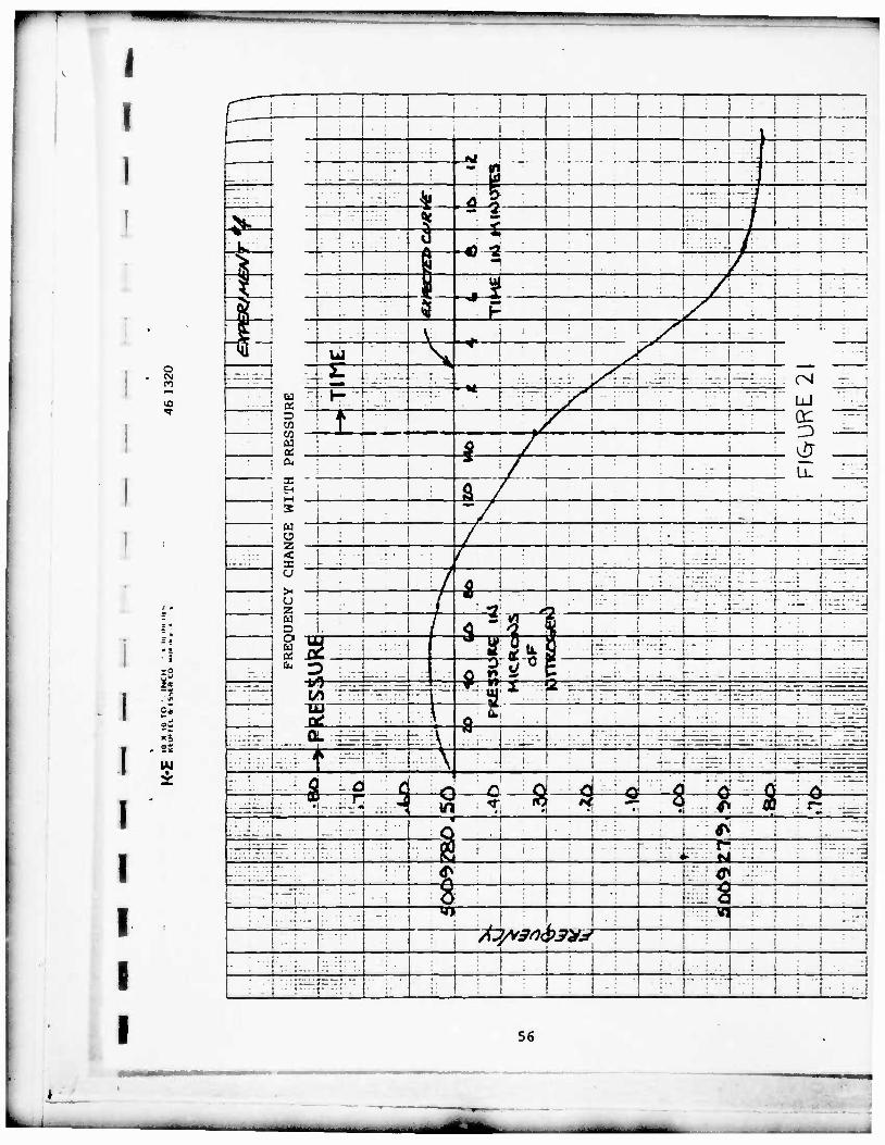
FREQUENCY CHANGE WITH PRESSURE 56
AVERAGE VALUE AND STANDARD DEVIATION OF THE 57 MAGNITUDE OF THE ACCELERATION SENSITIVITY VECTOR OF 5 MHz, 5TH OVERTONE PLANO-CONVEX AND DOUBLE-CONVEX CRYSTAL UNITS
23 RADIAL COMPONENT, THICKNESS COMPONENT, AND 58 MAGNITUDE OF THE ACCELERATION SENSITIVITY VECTOR
24 MAGNITUDE OF THE ACCELERATION SENSITIVITY 59 VECTOR VS. PSI ANGLE, 5 MHz, 5TH OVERTONE
25 ORTHOGONAL COMPONENTS OF THE ACCELERATION 60 SENSITIVITY VECTOR VS. MOUNTING
26 ESTIMATED CURVE FROM DATA TAKEN ON 26 61 5 MHz, 5TH OVERTONE CRYSTALS
27 SUMMARY OF "g" SENSITIVITY DATA FOR VARIOUS 62 MOUNTING ANGLES PSI OR 5 MHz, 5TH OVERTONE BI-CONVEX CRYSTALS
28 ACCELERATION SENSITIVITY FOR * = 25° ON 63 5.115 MHz, 5TH OVERTONE SC CUT CRYSTALS
29 FREQUENCY CHANGE DUE TO 0.75°C/MIN 64
30 FREQUENCY VS. CURRENT FOR 'SC' CUT 65 CRYSTALS WITH DIFFERENT 0 ANGLES
-lil-
'

i *^ y
FIGURE NO,
31
31A
32
33A
33B
33C
3 3D
34
35A
35B
36
LIST OF FIGURES - (CONTINUED)
NOMENCLATURE PAGE
FREQUENCY VS. TEMPERATURE FOR SC CUT 66 CRYSTALS WITH 0 = 25°
TYPICAL MOUNTS USED ON 10.054 MHz, 67 3RD OVERTONE SC CUT CRYSTALS
ELECTRICAL AND ACCELERATION DATA FOR 68 10.054 MHz, 3RD OVERTONE, PLANO CONVEX
ACCELERATION DATA ON 10.230400 MHz/3/SC 69 CRYSTAL, SERIAL NO. 4182
ACCELERATION DATA ON 10.230400 MHz/3/SC 70 CRYSTAL, SERIAL NO. 4184
ACCELERATION DATA ON 10.230400 MHz/3/SC 71 CRYSTAL, SERIAL NO. 4185
ACCELERATION DATA ON 10.230400 MHz/3/SC 72 CRYSTAL, SERIAL NO. 4187
MAGNITUDE OF THE ACCELERATION SENSITIVITY 73 VECTOR FOR 10 MHz, 3RD OVERTONE CRYSTAL UNITS
CRYSTAL ASSEMBLY FINAL DATA SHEET 74
CRYSTAL ASSEMBLY FINAL DATA SHEET 75
ACCELERATION SENSITIVITY VECTOR COMPONENTS 76 AT 10 MHz
37 FINAL DATA SHEET 78
APPENDIX I FURTHER DEVELOPMENTS ON SC CUT CRYSTAL 79
I I I I
-iv-
-•-». -•
—««.HMMki I Ml •--
l l INTRODUCTION
The principal object of this contract was the development of
vibration resistant quartz crystal resonators of the SC or
"stress compensated" type. In this reqard an improvement of
about 1 order of maqnitude, from a few parts in 10^ per g to a
few parts in 1010 per g, was accomplished at 5 MHz. The
limited number of experiments performed on 10 and 20MHz crystals
did not result in a comparable improvement in their "g" sensiti-
vity.
Attempts to correlate particular low "g" sensitivity crystal
units to specific design or assembly variations was, in most
instances, unsuccessful. Although the yield was increased, the
reasons for the improvement are not well understood.
During the course of the investigation many problems of de-
sign and measurement had to be solved, and contributions to the
state-of-the-art are believed to have been made in the following
areas:
1. Accurate mounting of the crystal plate.
2. Measurement of the acceleration sensitivity vector by
the "2g" method.
3. Design of circuts to suppress the unwanted "B" mode.
..^i^ifci ^^^guMMaatMi

I I I I
I I 1
4. Accurate cutting of quartz blanks.
5. Accurate X-ray orientation measurements.
6. Frequency adjustment at controlled temperatures.
Separate measurements were also carried out to investigate
the effects of pressure and temperature gradients on frequency.
Of 42, 5 MHz 5th overtone crystal units tested with
<$> = 23.75° or higher on this contract (da1 * not presented here),
the average magnitude of the acceleration sensitivity vector was
4.03 x 10~10/g with a standard deviation of
1.05 x 10⁻¹vg. There were 17 units between 1 and
3 x 10~^u/g. The test methods were insufficient to resolve
anything closer than 1 x 10~^/g, and final figures will be
determined when units are installed in their respective final
oven-oscillator packages and allowed to stabilize. Yields of
crystal units 3 x 10~'"/g or better of 70% have been
experienced in some lots, although the lots were not large enough
to be statistically significant. The data is presented only as
evidence of a possible solution to the problem. Figure 1 shows
the crystal designs used on this contract.
L-. I • -~

I I
II. PROGRESS
A. Orientation and Cutting of Quartz Blanks
In the cutting of blanks from the quartz bars every attempt
has been made to accurately cut blanks so that little or no cor-
recting is necessary. To this end, each bar has its -X surface
and one Z surface made flat and parallel to the underlying cry-
stal plane to within 1 minute of arc. Correction at this stage
can be more accurately and easily accomplished than at later
stages. Mechanical orientation is then carried out by fixtures
that can be set to well within 1 minute of the desired orienta-
tion. Both sawing and grinding techniques have been used to pro-
duce uniformly oriented blanks. The grinding technique is also
used to make small corrections if necessary.
The SC cut crystal design has an inflection temperature
near 95°C, making angle control critical at turnover temperatures
from 80 to 95"C. For this reason, some crystals have been cut to
raise the inflection temperature to near 110 C, with little
change in overall characteristics. Figure 2 illustrates this
fact by showing the range of angle control required to obtain the
necessary turnover range. We have assumed a 10°C window as being
adequate for most applications.
. — •

I I
I I I I
Use of X-rays to Measure Orientation Angles
Two methods of measuring the quartz plate orientation have
been used. The first using an existing X-ray goniometer set for
"AT cut" measurements, and the second using an X-ray goniometer
dedicated to "SC cut" measurements. Both systems are shown in
Figure 3.
For the measurement of SC cut plates on an AT type X-ray,
our system consists of tilting the blank to "undo" the 0 angle
and permit the use of the 01.1 plane as in the measurement of an
AT blank. The crystal blank is then rotated -14° about its
thickness so that its measured 9" angle is even closer to that
of the reference plane, 38° 12.7', than the AT cut. This -14°
angle is the "natural" angle of the blank as cut from an X, Y, Z
bar. The exact angle is ty = tan-1 (tan 4> sin 9) . A simi-
lar technique is used to measure the 0 angle, independent of the
value of 9.
The blanks are cut from a highly corrected quartz bar, using
the same 9" angle as in the X-ray measurement. In effect, we
have uncoupled the two angles, (? and 9, and the angle setting
on the saw table, 9", is the same as the angle read on the X-ray
goniometer, thus permitting an operator to easily make small
corrections in 9.
The measured angle )?' is related to J? by the know angle of
the 01.1 plane. The measured angle 9" is related to 9 by the
II»I«<I—i^^M^n —•—- - - •

—„
value of 0. The X-ray goniometer which we use measures 0% by
reference to a standard and reads in degrees, minutes, and
seconds. 9" is similarly read on a micrometer dial that reads
in inches, 0.0001" corresponding to 2 seconds of arc.
A program has been written for the hand-held Sharp EL5100
Calculator. It is only necessary to enter the scale reading from
the X-ray goniometer and push one button for the specified angles
to appear. Conversion from degrees, minutes, seconds to decimal
degrees, comparison with reference crystal readings, inter-
relationships of the various angles, etc., are all carried out by
the single key stroke.
The actual programs are as follows:
1. f(AB) = tan"1 (tan ((A-B) X D) + 36.3) X Cos C = 9
2. f(EF) = sin"1 (sin (E + deg - F •*• deg - 18.45) -r .7857) = 0
3. 6" = 36.3 + (A-B) X D, for saw table setting
Where:
A • X-ray dial reading for 0, unknown crystal
B = X-ray dial reading for 0, reference crystal
C = 0 angle in decimal degrees
D = .0555
E • X-ray dial reading for 0, unknown crystal
F = X-ray dial reading for 0, reference crystal
, - - - , ^«•BMfc- . . . .. . •. •• -J

I I
1 i
I I
The advantages and disadvantages are as follows:
Advantages:
1. The method used an existing AT set-up.
2. The angle measured, 9", was identical to the angle set
on the saw table, making angle correction direct and
simple.
3. It was capable of making absolute measurements, as well
as ones using a reference standard.
Disadvantages:
1. The tilt necessary to brinq the AT X-ray plane (01.1)
vertical to the goniometer table was about 15°. This
made the data measurement very sensitive to the refer-
ence flat (Psi) angle.
2. Calculating Theta from Theta double prime required a
knowledge of Phi and calculation of "turn over" required
both Theta and Phi. (By the term "turn over" we mean
the temperature at which the temperature coefficient of
frequency is zero).
The second method, which is preferable, makes use of a very
precise, universal, double crystal X-ray goniometer. The sensi-
tivity is ten (10) seconds of arc. Some new approaches have been
developed which simplify the measurement of Phi, Theta and Psi,
and what may be even more significant a way has been found to
relate the turnover temperature of the finished crystal to a sin-
gle angular measurement with no calculations necessary other than
a simple graph.
—

In the new method of measuring, the crystal blank is consi-
dered as a rotated X-cut, making Phi about 8* rather than 22°.
This derives, of course, from the three-fold symmetry of quartz.
Theta is still near 34° and Psi ranges from 0 to -15* as before.
The SC rotational symbol is usually given as YXwl $0^ with $ =
21.95° and 0 = 33.9° properly called a rotated Y cut. It would
be just as correct to refer to the SC as a rotated X-cut, in which
case the symbol becomes XYwl 4>0^ with Phi = 8.05* and
Theta - 33.9*. When this is done, the thickness of the plate will
be X', and 91 is the rotation about Y'. If the change in
nomenclature is confusing, then we could use a rotated Y
nomenclature as before and just substitute (30 - 4>v) in the
equations presented for the rotated Y cut.
For the measurement of Phi and Theta we use the 22.3 plane,
whose normal lies in the X-Z plane at 34 degrees 17 minutes from
X. This is almost exactly Theta and only 8* away from Phi. The
Bragg angle is 48°, so the angle between the X-ray beam and the
ionization chamber is 48". The cosine of 34 degrees 17 minutes
is .82626, and <P = sin-1 l^ffls/* Theta prime (9') is the
angle measured by the X-ray with the crystal blank mounted on a
normal vacuum chuck barrel with the Y' (the old X') axis parallel
to the table. One Z face of the uncut quartz bar is usually cor-
rected to provide the Y' direction in the blank, which in this
case, is not very critical. For measurement of Theta, (9) a
mild tilt, which is not critical, is provided to compensate for <t>

1 I I
, _i /tan 9'\ and <p - tan \~~cos~Z)* Phl 1S tne angle measured as
described above and Theta (91) prime is the angle measured by
the X-ray. The measurement is made using a non-critical 6° tilt
back and with the Z1 axis parallel to the Table. The correction
for <J>' and 9' to arrive at <t> and 9 are now small enough to
present on a simple sheet of graph paper. A calculator is not
necessary once the plots are made. Figure 4 shows the
relationship between 0 and 9 for a constant turn over
temperature. The upper curve is taken from a paper by Ballato and
Iafrate (1976 30th Annual Frequency Control Symposium). As $
departs from the AT and goes through FC, ITC, etc. to the SC, the
angle 9 must be changed accordingly to give the same turn-over
temperature. On the same graph, we have plotted the values of
9' which would result in the 9 values shown. Note especially
that over the range of interest the data is invariant with the
value of 4>. For specified <t>'s from 22* to 24°, 9 varies only
0.6 minutes and for 4> 's between 22" and 23* 9 varies only .02
minutes.
Figure 5 shows the values of 9', the angle measured directly
by the X-ray, for SC turn-over temperatures between 50* and 85*C,
for any reasonable $ value.
This chart, of course, is for a particular design. For
other contours and other frequencies the curve would be the same
but the left-hand scale would be shifted up or down slightly.

In a test of 8, 5 MHz 5th overtone units, using Premium Q
swept quartz, the values of &' as read from the X-ray goniome-
ter were 33.540 ±0.012 degrees. The turnover temperature ranged
from 60* to 67° as would be predicted.
I
Should it be desirable to measure the $ angle, either for
measuring existing flats or for determining the place to generate
flats, this can be done at either the X' or Z' axes, using the
rotated Y cut nomenclature. Using a Y axis reflection, the 02.0
plane, the X' direction of the plate will be some "A" degrees
away from the X-ray indication. Where A = tan-1 (tan 4> sin &).
For a 4>x of 6.25° (<j>y = 23.75°) and a & of 33.91", A = -3.496*.
Of course, a prepared crystal standard can also be used to verify
this relationship. For reflections from the Z' edge, we can use
an X-ray plane whose normal is in the X-Z plane and is 90° from
the 22.3 plane used for measuring Phi. Such a plane is the 11.3
plane at 53.75° and Bragg angle 32°.
•
An X-ray fixture which will both measure and generate an
accurate mounting flat on the edge of the crystal plate is shown
on Figure 6.
The location of the mounting flats (ty angle) can also be
measured by use of a microscope using both orthoscopic and cono-
scopic viewing. A Zeiss rotating stage is used which can be read
to within 10 minutes of arc. In the normal viewing mode, the
quality of the flat and its bearing against a reference edge can
-- —

I I
be observed. In the conoscopic mode, an isoqyre (sharp black
line) can be observed which is related to the direction of the
optic axis. The method is as follows: using the Z direction of
an SC cut reference standard, find the stage setting for an
isogyre crossing bottom to top as the stage is rotated clockwise.
Replace the standard with the quartz plate to be measured and
rotate the stage to find the same isogyre relationship. A simple
calculation will give the location of the flat. The readings
taken in this manner have a standard deviation of 0.35 degrees.
C. Mounting Techniques for Reducing Acceleration Sensitivity
There is definitely a relationship between one, the location
and size of the mounting points at the edge of the crystal plate,
typically accomplished by thermo-compression bonding a ribbon
support member to the edge, and, two, the magnitude and direction
of the acceleration sensitivity vector.
The configuration used has been that of three points, 90°
apart. The bonds should be centrally located on the bonding flat
of the crystal and the tool impression should be limited in size
and preferably centrally located on the axis of the ribbon. The
first five crystals subjected to vibration tests had the follow-
ing results:
10
i - • - -

T
I
' i
TABLE I
Crystal R
1.4
T T
1370 1.4 1.96
1371 4.2 - -
1373 6.5 1.0 6.6
1375 7.0 1.8 7.2
1376 1.4 1.7 2.2
See Figure 7
See Figure 8
See Figure 9
See Figure 10
See Figure 11
The need for centrally locating the bonds is apparently
caused by the establishment of mechanical couples in the crystal
plate. Because the sample is small, re-processed and newly
fabricated crystals were photographed prior to sealing. Results
were then compared with the photographic evidence. Our present
TC bonded crystals use an aluminum clad nickel ribbon. The
aluminum side of the ribbon is bonded to the plated edge of the
crystal under constant heat and pressure.
Independently, Professor Peter Lee1 of Princeton University
calculated the same location for mounting points (Psi ( ) angle)
as we had determined experimentally.
Professor Lee first defined the coefficient of acceleration
sensitivity as
„ Af . 1 Ka " f« ~F" -o r fo/n
F = force on plate = mass of plate x acceleration
fo • frequency of resonator
n = overtone number
d • diameter of resonator
1 34thAnnual Symposium on Frequency Control; Page 403, 1980.
11
J- •MMM m—*t

•••• — ••
I I I
I 1 I
This is similar to the coefficient of force sensitivity Kf.
Then for each support position ty, Ka is computed as a function
of acceleration direction. From this, one can obtain | Ka | max,
the absolute value of Ka maximum.
This process was repeated for a range of 4> values, and he was
able to obtain values of | Ka | max as a function of ty. See
Figure 12, which shows Professor Lee's calculated values as a
solid line and FEI's data as points.
A new ribbon for TC bonding been developed^. it consists
of a stripe of gold coined to a nickel ribbon. A supply of
various sample lots of nickel with the gold bonding stripe was
received from Technical Materials Incorporated, and was used for
our experimental studies. FEI had to anneal the ribbon, since the
samples received are approximately 1/4 hard. Initial data shows
that the bonds were, at a minimum, equivalent in strength. A
diagram of the ribbon is contained in "Further Developments on
'SC Cut Crystals" by B. Goldfrank and A. Warner, Figures 9, 10
and 11, attached to this report, in Appendix I.
Because the gold stripe ran perpendicular to the ribbon
length, methods of precisely cutting the ribbon to the appropriate
^Evaluation of Interposed Gold Wire Leads for TC Bonded External HIC Connections; H. N. Keller, Bell Laboratories, Allentown, Pa. and C. E. Apgar, Western Electric Co., Allentown, Pa.
12
MMMM

I dimensions, ±0.001", had to be worked out. Although we have made
completed units, none have had bonds which were exactly centered
or uniform in thickness. Extremely close control of all
processing and fixturing parameters was needed in order to
discover the exact effect of the mounting point size and location
on the magnitude of the acceleration sensiivity vector.
Ribbons with the coined triangular stripe along the length,
rather than the width have also been used, thus eliminating a
very difficult positioning problem at the quartz interface. New
welding techniques have been developed at FEI to permit the
direct attachment of the gold stripe of the ribbon to the gold-
plated pins of a C type header. This eliminates the need for the
usual fold and/or removal of the gold to expose the nickel surface.
This technique has proved to be very successful, and was
implemented on the final test lots of crystals.
Three 5 MHz 5th overtone SC crystal units, which were
mounted using nickel ribbons with a lengthwise gold stripe .010"
wide were disassembled to observe the nature of the bond to the
quartz mounting flat. The bonding was done with a tip temperature
of 450°C and a pressure to ten pounds. The size of the tool was
.020" wide. The bonded area was slightly larger than .010 x .020
inches, and of a shape as shown on Figure 13. In all cases, par-
ticles of quartz adhered to the ribbon after disassembly. Two
units similarly mounted were subjected to vibration from 10 to
2000 Hz at vibration levels from 10g to 60g, without any apparent
13
mm

I
——
I.
damage. Pull tests of these bonds are typically higher than
those made with Al-Ni ribbons by 36%, as shown in Figure 14.
D. Adjustment to Frequency at the Operating Temperature
The SC cut crystal design has such a poor temperature coef-
ficient of frequency at room temperature that it is necessary to
calibrate the unit at an elevated temperature.
Frequency Electronics has fabricated a three position hot
tuner. This machine allows us to adjust SC cut crystals to within
0.1 PPM.
The three positions of the tuner are mounted on a fourteen
inch base plate and covered by a twelve inch spherical dome. A
picture of one of the heads is shown in Figure 15. The heater
block and Pi network are removable for easy maintenance and/or
changeover to a different header configuration. The filament is
shielded (not shown) front and back to eliminate any possible
shorting of the internal electronics. The crystal temperature
can be continuously monitored and is accurate to within ±1°C.
This is more than adequate for any SC cut crystal, since there is
normally a 4*C to 6"C range where the crystal frequency does not
change more than 1.5 Hz.
The Pi networks all have one common ground as do the inputs
and outputs for measuring the crystal frequency. The tuner heads
14
1 •••—••-- - - .

I I I
I I
are connected to an eight pin feed-thru, with three inputs, three
outputs and two grounds. All other electrical connections are
through a separate twenty pin feed-thru.
The entire tuner is under a laminar flow hood. The vacuum
cycle consists of three minutes on a graphite pump, fifteen to
twenty minutes on a vac-sorb pump and sufficient time on the ion
pump to reach 5 x 10~7 torr. A schematic of the system is
shown in Figure 16.
E. Measurement of the Acceleration Sensitivity Vector
Two methods of testing crystal units are currently in use.
One is the use of a vibration table to generate known 'g' levels
and the other is a static test using the acceleration of gravity,
known as a '2g' tipover test. In both methods, the components of
the acceleration vector3 are measured in three mutually perpen-
dicular directions, and the vector magnitude and direction calcu-
lated. In initial studies the static method is preferred because
it measures the acceleration sensitivity vector apart from any
resonance effects. Crystal units are mounted in FEI designed
standard oven-oscillators. Improvements have been made by alter-
ing the temperature control in the crystal oven and making the
temperature setting external to the oven. Temperatures from 40°
to 100°C can be set by a 10 turn potentiometer. In addition, a
3 The Effect of Vibration on Frequency Standards and Clocks, R. L. Filler, USAERADCOM, Proceedings 35th Annual Symposium on Frequency Control, 1981.
15
H_**M

• «'
i I 3.3 megohm resistor was added in parallel with the crystal termi-
nals, to remove any D.C. bias generated during the warmup
period.
2g turnover acceleration tests of normal crystals can be run
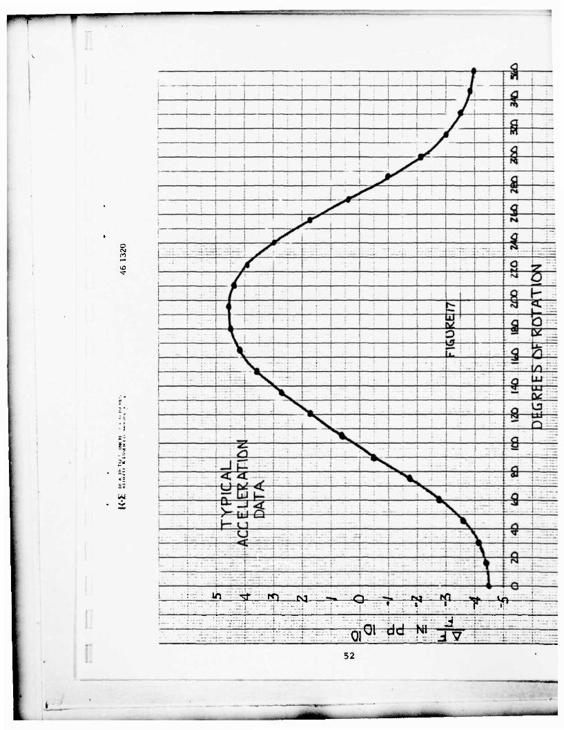
at the rate of one an hour. Figure 17 shows the type of data
that can be taken.
..
In making 2g turnover tests, particularly where very low
acceleration coefficients are to be measured, one observes that
false frequency readings of a few parts in 101^ often occur
due to drift, erratic behavior from initial strain relief, noise,
and possibly circuit and cabling variations. In order to sepa-
rate these variables from the actual acceleration effect on
frequency the following method of taking data is used, with the
crystal unit mounted in its oven-oscillator and stabilized for
one hour, five successive readings of frequencies are taken at 5
second intervals, then the oven is re-oriented by 180°, and five
more readings taken.
By repeating this procedure three times, the true accelera-
tion effect for this one orientation can usually be ascertained
1 I
16
—._
11 — '•-' I i^m^^^ •••••• •
I
even in the presence of drift and noise, however it is still
possible to have a 20% error in any given measurement. Further,
knowing that the acceleration effect vs. angle in any plane is
sinsuoidal in shape, a second check for false or suspected values
is provided by using several sets of readings, each 90° apart in
the plane of the quartz plate. An example is given for both a
good and a difficult measurement in Figure 18.
F. Oscillator Circuits
In the SC design, the orthogonal thickness shear mode, known
as the B mode, is more strongly excited than the desired C mode.
The suppression of the B mode has been left to the circuit
designer.4 Successfully designed circuits for 5, 10, and 20
MHz have been made which suppress any frequency other than the
one for which the circuit was designed. A "B" mode 1/3 the
resistance and only 8% removed in frequency will not oscillate in
these circuits. Figure 19 shows a typical design.
4"Design of Crystal and Other Harmonic Oscillators' by Benjamin Parzen, Wiley Interscience, 1982
I 17
-

•
I I I III. TESTS AND RESULTS
A. Pressure vs. Frequency of the SC Cut Crystal
Pressure vs. frequency studies were conducted using the
hot-tuner with its variable temperature control and excellent
vacuum.
Pressure sensitivity tests were made, using a 5 MHz, 5th
overtone, SC crystal, with a turnover of 85°C. The crystal unit
was inserted into a temperature controlled block inside the high
vacuum system, with the flange of the crystal holder in intimate
contact with the block. The temperature under high vacuum was
controlled at the turnover temperature of 85°C ±0.1 "C and
independently measured. Tie greatest temperature change, going
from air to vacuum, was less than 1°C, and would account for less
than 0.1 Hertz change in frequency at a steady state condition.
It was established that the effect of atmospheric
pressure on frequency is approximately +1.5 Hertz, about
double reported by Stockbridge^ for the AT cut crystal.
If the curve is nearly linear as shown by Stockbridge,
5Vacuum Microbalance Techniques, Vol. 5, 1966, CD, Stockbridge, Plenum Press.
18
- — -

wm
I I l
I
!
then 1000 microns of nitrogen, introduced, should have a very
small positive effect on frequency, about 0.002 Hertz,
(4 x 10⁻¹⁰ Hz/torr).
After flushing the vacuum chamber several times with
nitrogen, a base frequency at 85°C in high vacuum was established
at 5009280.51 Hertz. A series of experiments was then run. Each
experiment was started at the same initial frequency.
a) 500 microns of nitrogen was introduced into the vacuum
chamber. The frequency increased almost instantaneously
by 0.25 Hertz and then gradually went down 1.5 Hertz.
The initial rise is in the right direction, but too
large. The frequency decrease with time is believed to
be absorption of some contaminant, possibly from the
nitrogen feed line. (See Figure 20).
b) 500 microns of nitrogen was introduced and immediately
pumped back to 10 microns. The effect was to lower the
frequency by 0.1 Hertz. In high vacuum, the frequency
slowly returned to the original frequency.
c) 10 microns of nitrogen was very carefully introduced
through a bleed valve. There was no significant change
in frequency from the established base frequency.
19
>--*i^M^^- •

r
I I d) A slow steady leak of nitrogen was carefully established
at approximately 50 microns per minute, and the frequency
versus pressure recorded. The frequency rose initially
by 0.05 Hertz at 50 microns, and lowered by 0.50 Hertz at
1000 microns. Upon closing the leak valve the frequency
continued to decrease. See Figure 21.
The conclusions are:
1) Contamination in the gas delivery systems is the cause
for all negative frequency changes with pressure.
2) Sudden inputs of gas may disturb the temperature
equilibrium enough to account for the temporary increase
in frequency in experiments "a" and "d".
3) There is no anomalous change in crystal frequency from
pressure changes that might occur due to outgassing in
the crystal enclosure, as shown in experiment "c". The
effect is small, on the order of 4 x 10"10/torr.
B. Magnitude of the Acceleration Sensitivity Vector vs. Orientation
It has been suggested6 that if the proper <p angle and mounting
method were found and used, then a plano-convex crystal blank should
have the same good acceleration coefficient as a double-convex
6Dr. John Vig, USAERADCOM, private communication - suggestion based on results obtained at USAERADCOM on four-point mounted resonators.
20
I • - -

I
blank. The theoretical $ angle for stress compensation is often
quoted as 21.95°. Therefore, a group of eighteen 5 MHz, 5th
overtone crystal units were prepared from Premium Q swept* quartz
with angles near 22° and near 23.7 5°, both plano-convex and
bi-convex, and with • angles near -14° and -17°. The results are
summarized on Figure 22. The variation in the magnitude of the
acceleration coefficient in the radial direction is not enough to
be significant. However, in the thickness direction, it is clear
that the double-convex shape is 3 to 4 times better, and with the
present design is necessary to the goal of 1 x 10~1« per g.
The original design at <t> = 23.75° is marginally better for the
magnitude of the acceleration sensitivity vector.
Professor Peter Lee, of the Civil Engineering Department,
Princeton University has been most helpful in providing a
theoretical basis for the relationship between orientation angles
(4> , 9, <M and the magnitude of the acceleration sensitivity -+•
vector, lrl . One of his studies7 indicated that a * of 21.95° -*•
and i> of -25° could provide a Ml considerably less than
1 x 10~10/g. Crystal units, 5 MHz 5th overtone were made
with a 4> near 21.95° and $ angles of -23°, -25°, and -27°. The
•Sawyer Research Products, Eastlake, Ohio, Registered Material
7Letter, P.C.Y. Lee to A.W. Warner, April 9, 1981
21
I
— -• ^

I
results showed magnitudes of the acceleration sensitivity vector
typical of previous designs at <j> = 23.75° and \p = -15°. The
results are summarized on Figure 23.
A group of quartz blanks was procured from Colorado Crystal
Corp.* with a nominal value of 4> of 21.95° and 9 such as to put
the turn-over temperature near 50°C. These blanks were prepared
from premium Q quartz, not swept, and are 4.6 MHz at the 5th
overtone. Twenty of these blanks have been reprocessed at FEI
for operation at 5 MHz. The design is double-convex, 2 1/8
diopter per side, and polished. The were divided into five
groups of four each, with <p angles of +5, -5, -10, -15, and -20
degrees. All units were ribbon mounted by thermo-compression
bonding at 3 points 90° apart, with two of the points near the
Z" axis. The 2g turnover tests were made in four directions
radially and one in the thickness direction, in order to give
some redundancy to the measurement.
The results are listed on Figures 24 and 25. Figure 24
gives the actual location of the ty angle to the nearest degree,
the value of <$> to 0.1 degree, the resistance R1 , the turn-over
temperature, and the magnitude of the acceleration sensitivity
•Colorado Crystal Corp., 2303 W. 8th Street, Loveland, Colorado 80537
22
•M ___

——
I
I I
vector. In Figure 25, the data is presented in a way to show any
correlation of the magnitude of the acceleration sensitivity
vector with (1) the spread in the location of the three 90"
mounting flats on the quartz plate, (2) the vector direction in
the plane of the crystal, and (3) the position of the mounting
points relative to the crystal plate flats. The nomenclature is
from Gualtieri,** A and B are Z" axis, C is normal to Z" axis.
The acceleration effect is highly variable, i.e., no correlation
was found. The vector magnitudes in the thickness direction were
all near lPP1010/g and had only a small effect on the angle
and magnitude of the acceleration sensitivity vector. There may
be a correlation between the abnormally high vector magnitude of
crystal unit D4 and the relatively large errors in the placement
of mounting points on that crystal plate, although this is by no
means conclusive. In the B series, only one unit was suitable for
acceleration testing.
Figure 26 is an attempt to correlate the approximate
magnitude of the acceleration sensitivity vector versus mounting
angle if» with one of the theoretical curves of Professor Peter Lee.
8DELET-TR-81-5 "A simple method for location of the mounting positions for low acceleration sensitivitv SC cut resonators", J. Gualtieri, USAERADCOM, 1981.
23
-— —•

-"-
I 1
i I I I I
If we add the previous data taken at i> = -25° and • = 21.95, and
if we are selective in choosing values, a curve similar in shape
can be drawn, showing optimum mounting angle near ty = 14*.
The group of twenty 5 MHz 5th overtone units with <$> = 21.95°
and various ($) angles were reprocessed using gold-stripe nickel
ribbons (see Figure 27). Traceability of the individual units
was not maintained, but the overall acceleration sensitivity
vector magnitude was greatly improved. Omitting two defective
units in each case, the original magnitude of the acceleration
sensitivity vector was 6.6 x 10~^u/g average, 3.11 standard
deviation for 15 units and was 4.8 average, 2.35 standard
deviation for 17 units of the reprocessed crystal units.
24
••—•- - - ——d^*^^—-• —— -—ü^- -^- ^ -

C. Experimental Crystal Units at $ = 25", 5 MHz 5th Overtone
A group of eight 5.115 MHz 5th overtone units with an
experimental <j> angle of 25° and ty angles near -15° were processed
and tested. Two units are obviously defective, having a large
thickness component of the acceleration vector and high
resistance, Ri. If these are omitted, then the remaining six
units have remarkably low acceleration vectors. The average
reading of the magnitude of the acceleration sensitivity vector
is 2.64 x 10~10/g with standard deviation of 1.73. Five of
the six units are between 1 and 3 x 10~10/g, or 83%. This
is the best yield experienced so far. Variation in <JJ angle from
-14° to -18" did not appear to any effect.
Because of this success, the group of crystals was enlarged
to 17 units. The data on these crystals is given in Figure 28.
For all 17 units, the average vector magnitude is 5.52 x
10-10/g standard deviation 4.46. If the three worst units
are eliminated, the average vector magnitude is 3.75 x
10-10/g, standard deviation 2.04.
[ 25
— M .. • --. • -^

" —•—•
I
!
The crystal units with a <f> angle of 25° were further tested
to evaluate the negative effect of using a <f> angle 3° from that
considered optimum. Two units were tested for the effect of
temperature gradients, amplitude of vibration (drive level) and
infection point of the frequency vs. temperature curve. These
results were conpared with those of crystal units having <t> angles
of 21.95° and 23.75°.
(a) Temperature Gradient Effect.
Six crystal units of standard design were selected for
test, two each at <t> = 21.95°, 23.75°, and 25°. They
were all given heat runs from 30° to 70°C in an
automated slew test box. The rate of temperature change
was regulated at 0.75°C per minute. The maximum
frequency at turnover for both increasing and decreasing
temperature was used to find the temperature gradient
effect at this rate of change. The results are shown on
Figure 29. The numbers are < 1, 8, and 10"9
respectively.
26
«MWMiMMHIl^ —

p-P—
I I
(b) Amplitude of Vibration Effect.
The same six crystal units above were operated at
turnover temperature with varying drive levels. The
frequency vs. crystal current was plotted for 4> = 22°
and 25°, for currents of 10 pA to 1000 uA, with the
frequency normalized at 100 pA (see Figure 30). Below
100 uA, the frequency tends to be unstable, and above
300 pA, the effect of drive level becomes significant
with a slope greater than 1 x 10~10/pA. Between
100 and 300 pA, all units behaved about the same.
(c) Frequency-Temperature Characteristic.
Three crystal units with a • angle of 25° were operated
over the temperature range of 25 to 180°C. The turnover
temperatures are 62, 63, and 65°C, and the inflection
temperature is about 122*C, as shown on Figure 31.
D. J Mount and Diamond Mount Crystal Units
1) 10 MHz, third Overtone
"J" and diamond mounts, as shown in Figure 31A, were
evaluated on 5 MHz, third overtone, 10 MHz, third
overtone and fifth overtones and 20 MHz, fifth overtones
for acceleration sensitivity.
27

11
One group of 10.054 MHz, third overtone crystals were
processed twice. The initial fabrication used the
standard diamond notch mount. Electrical and
acceleration data were taken. The crystals were then
disassembled, cleaned, reprocessed, and acceleration
data re-taken. The data is presented in Figure 32.
Four additional third overtone crystals, at
10.230400 MHz were processed and tested. The initial
plating was done at 7 x 10~8 torr, the final
frequency adjustment at 85*C and 5 x 10~7 torr and
sealed at pressures between 3 x 10"? and 5 x TO""'
torr after hydrogen firing. Test results are shown in
Figures 33A to 33D. Twenty-eight crystal units at
10.054 MHz were measured for acceleration sensitivity in
the same manner as previously described, i.e., by 2g
turnover at the rotated X, Y, and z axes of axes of the
crystal plate. The three 90° mounting points are at
both ends of the rotated z axis and the negative end of
the rotated X axis. Y is in the direction of the plate
thickness. The magnitude of the acceleration
sensitivity vector is the square root of the sum of the
' 28
I I
1 !
squares of the X, Y, and Z components. Figure 34 lists
the test results. The average of the absolute value of
gamma r^v is 10-71 with a ° = 2.97. The crystals
were manufactured using the standard techniques
developed by Frequency Electronics for epoxy mounted
crystals. A diamond notch mount was used. Complete
electrical data is contained in Figures 35A and 35B.
Data on 30 additional units, one of which was repeated
(#4750) is included in Figure 36. As noted, the average
was 11.33 x 10~1(Vg with a standard deviation of
5.89.
2) 5.115 MHz, Third Overtone
Ten chemically polished, plano-convex crystals were
supplied to FEI by ERADCOM. These were assembled using
"J" mounts, on three posts, 90° apart. The initial data
taken, showed large radial acceleration effects. This
was due to random mounting caused by the lack of an
orientation flat. The data followed, however, the
theoretical curve prepared by Professor Peter Lee of
Princeton University. (See Figure 12). The crystals
were subsequently reprocessed and correctly mounted by
29
L — -^-^Mfc ••' —'

I I the addition of an orientation flat. The flat was added
by X-ray and cross-polaroid techniques. The
acceleration results, which we expected to be excellent,
were disappointingly bad ranging from 1 to 58 x
101(Vg and averaging 35.7 x 10l0/g. These
crystals were reprocessed a second time and mounted
using the cross-polaroid technique and then pasted. The
average magnitude of the radial component of the
acceleration sensitivity vector was 11.6 x 10"*'Q/g
with a standard deviation of 1.83. The average
thickness component was 27.6 x 10~^/g with a
standard deviation of 7.17. The maximum acceleration
effect in the radial direction is given separately from
that of the thickness direction because of the high
value of the latter.
3) 20 MHz, Fifth Overtone Crystals
Twelve units were constructed using the design shown in
Figure 1. The series resistance was less than 100 ohms
and the Q was greater than 500,000. Of the five units
tested, the average value of r was 6.57 x 10⁻¹⁰/g
with a standard deviation of 2.28 x 10⁻¹⁰/g.
Complete data is given in Figure 37.
30

T-
I I
I I
IV. DISCUSSIONS AND CONCLUSIONS
1. The search for an optimum design for acceleration
resistant units is continuing. Attempts to associate
small manufacturing deviations with poor performance
have not succeeded. Some evidence exists to indicate
that an increase in the value of the angle beyond
21.95°, perhaps to as high as 25°, can yield a higher
percentage of 5 MHz 5th overtone crystal units with
coefficients near 1 x 10~1u/g. Plano-convex
crystal designs have shown a high thickness component of
the acceleration sensitivity vector which is not
balanced out by the mounting variations used so far.
2. 10 and 20 MHz crystal units, which have not yet had TC
bond holders designed for them, have not exhibited low
acceleration sensitivity vector magnitudes comparable to
the TC bonded 5 MHz assigns. The 20 MHz design does
show some promise as it is a balanced crystal.
3. The "single-angle" X-ray method of measuring SC blanks
is proving both easy to carry out and accurate.
31

—— 1
4. Gold stripe ribbons with a lengthwise gold stripe can
now be successfully welded. Significantly higher yields
of 5 MHz 5th overtone crystal units with acceleration
sensitivity vectors less than j x 10~1(Vg have
been obtained.
5. Tests of thermo-compression bonding using gold stripe
nickel ribbons indicate that compared to aluminum clad
ribons, pressures can be reduced to 6 ->ounds from 10
pounds and that tip and stage temperatures can be
reduced by 50°C, to 400° and 300°C respectively.
Attempts to further reduce the temperature weakened the
bond.
6. The indications from a small number of crystal units are
that 5 MHz units with 4> = 25° have lower acceleration
vector magnitudes and are less sensitive to the mounting
angle, 4>, than those with <$> = 21.95°.
Since this angle is 3° from the preferred angle, it is
necessary to re-evaluate the effect of drive level,
temperature gradients, inflection temperature, and
impedance level. For example, the impedance level is
20% higher than that of * = 23.75".
32

mmmmm •WVinaii —
I
i:
Further, since some of the best and worst results were
obtained from this group it is possible that there is
another variable that we have not been able to identify.
If this variable is identified in the future, these
experiments should be repeated.
Of these four characteristics, that of temperature
gradient is the most pronounced, and will have an effect
on the time for frequency stabilization following a
temperature change. The drive level effect appears to
be the same for all units tested, although the 2 units
at <t> = 21.95° showed less tendency for erratic frequency
readings at very low drive levels.
The higher inflection temperature of 122°C is a distinct
advantage for ease of manufacture of units, especially
those operating near 90°C. The higher impedance level
will require slightly more care in frequency
calibration, but once made, the crystal units should be
entirely satisfactory.
33
...•I .

W—"" ' '"•• '"•" ' " • " ' ' "• " ' ""
7. The 10 MHz crystal units have shown poor results
throughout. This is mainly due to the design with
secondary effects caused by mounting. This is evident
due to the better performance of the 20 MHz crystals
which have similar mounting structures, but are of a
balanced design. Results were typically 11.3 x 10~10/g
with a standard deviation of 5.9 x 10~10/g.
8. Testing of six 20 MHz units using the new test set shows
an average of the magnitude of the acceleration sensi-
tivity vector of 6.57 x 10~10/g with a standard
deviation of 2.28. Improved mounting techniques may
improve these results.
34
_—. ii i.^MMh — . ———
1 I
I I I I I I I
REFERENCES
1. 34th Annual Symposium on Frequency Control, Page 403, 1980.
2. Evaluation of Interposed Gold Wire Leads for TC Bonded External HIC Connections; H. N. Keller, Bell Laboratories, Allentown, PA and C. E. Apgar, Western Electric Co., Allentown PA.
3. The Effect of Vibration on Frequency Standards and Clocks, R. L. Filler, USAERADCOM, Proceedings 35th Annual Symposium on Frequency Control, 1981.
4. Design of Crystal and Other Harmonic Oscillators, B. Parzen, Wiley Interscience, 1982.
5. Vacuum Microbalance Techniques, Vol. 5, 1966, C. D. Stockbridge, Plenum Press.
6. Dr. John Vig, USAERADCOM, Private Communication.
7. Letter from P. C. Y. Lee to A. W. Warner, April 9, 1981.
8. DELET-TR-81-5, A Simple Method for Location of the Mounting Positions for Low Acceleration Sensitivity SC Cut Resonators, J. Gualtieri, USAERADCOM, 1981.
35
_

r^ „„„•I,-,.- .,.-•,.•••
— ü e 1> — c ~
'J —* :N o —. !N ±J ^o —l Ü* ;N X 0 *r in in \T> —' Z —» •-N ;N m> 3
o *~ ZL. a — O —i
T3 o 0 O C i^
;n r* O o — 2 2 33 M
r* o> 00 3> in T> \C fN • • • fl - r- • o O • 30 •o —i m «» •-* CJ CD
M — Q - • — ^ — — « i u X
«J a
< e r
o
t^ «- —
— — o 3 — in o
0
~ — oj
N =
rt in ^s
CM ^ — 0 6-
j/trV r
a i •w • o - - F
c ^ 0 J) S = <
m 2« *n CM © © © • 0 • © P» CM «- w •£ "~' .J. o •w W
fN o in "—' O QO «T in <N **"i V o> 0> o r» in
in in rsi
cr* en
ON cr*
CM
©
CM \0 in CM
ltd •*- 0 0
u U 3 3
<0 "3 ~— —» —— CM > > ^D in c* X u - in CM r-* MS ^* 3 3 w
0* -n
© o O Ü
© c *m s. 0 c CM © in *— U *r in CM o> V ±j t/9 01 e r- in fNI in 0 3 3 ^ CM c -M —• ^ en
CM a Q
c
c E
T3
(5 ^
II II
a. 3. c 0
—» mm —. © 0) 2 c •V © n^ r^ mm
fN CM fM C* in X >mt •• <N if> a ?"L in v «ft lu • c C • o in o
c c — © & u 3 M3 • c — <n in CD — •— 5 M
fN — —
B
il a C J c
36
a § w c
en 7. • a 7
1> n u Bfl 3 n 4-1
Ü H 10 -l (w u 3
C u 10 • 1 J 0 — < tn n u ^^ n M nj r? a, o > 01 • Ü (0 — •
o -H O fl — A-1 •
u> — >1
u n u
u • c « 0 c j-1 (0 14 <u — > » o -
It •»r
M CO
I •" in a — < u^ u
0 < WJ

1
o in
U3
5.
S3
Ui
37
M —~

n
OS a g 8 z s I I
I I
u
a
38
»ii —.

I
—
o
z»
: i 1 ! 1 II i
w I'I i ! ! • ! : I ! i • !
1 ^ i . 1 • 1 • 1 ! 1 1 1 !-H i ! ;• | I j i | I i
. I : . m
m
Kl
1 \| 1 1 ' L i : j : • 1 : -j
1 1 1 \l ! CD !
1 ' ! : ^o j -!
! V 1 1 • • • 1 ! 1 i i j : ! : I . ; : i.A.- ! 1 1 1 1 ! ' 1 !
: 15
:- i • i \ • l 1 | | | i IS 1 ..;:--.
i ! • : ! V i 1:1 : • ;
1 : \ •• "S ; .:
1 : ! \ i ! -: • . i r=
i trj •:. 1 : - i -'•
i • "Ö "_-"r;^r:
1 : : •* :: :" ' 1-'-: .Er. . '• \ \ •'• —• • . ..: . w —0==
• ; i : i \ : • I • j "-'':' • -
I x>
i •M rivij : 1 j i • *5 "rTr-
i ; i
UJ ! 4\' . 1 : i .;• "O . :^=r
! ! ! O II
U : J£\ | : ; 1 . I : rtr";E
1 . : l-MS ISA • 1 ; • : > - X ~
"Q- m . v\ ! I i P-; •^•J i j ..; jB •:•• U£V : : ! i • "Q
-•;; —
i • [- J x-*te 3-2=^ "'"'•AM''"::1' -: —t;-f ._.— J8_ • r ~.'.
i f ": M .: _j =±r=:
«*W—r— ri-A • :'. :
- j —: ... '&
; ' i : ... r. . ... ..._
i j i 1— 3 --: :: i\J ~ *' " /*0t : -; :...-i- . '•':': ." : ' • r n: -~" i :—i— 5TP rr •Ea ;
-••>• -:;—
1 •\ : ..: T \ ! :
—i:£: - ":/. -<t
.. :.: —
- 1 1 • *c d :.:. ••• i . i . \: . --- . . .. B1 -•zzzr:
• CD *2 \ : i I • :• .- *fl . ...
i k? ;zr m ..:—"":.-. :.;. ' : • ! - U-::-:- «J . _H
i to ==£ j •:: i j \; : 1 : ! ; i pfS . -- • i -- ,
; : - ui r • :__.; . . U ._ j : i • i:-;:::>:,,-
r : V3 -*2 ! ! \ i ! |,r.l .-•! ;-!."-;•• «_»" •:•"•!";
< r •. : . 1 • |-"-i [--• | |f r=^j=S -• »* . | _'.: :
i i *..,U ! ! • I •• . j j 1 £ ! • ! .
VJ ..«J,:,,|... ,:.!.- .1,-4 -.L.M-. L...: - .---:'- :]--•: - '—. r£ ~
~ :-;•:_: • •
t-- -J : 1 -"::--!-. ::^:
-•: • :
<*l •U rfl rf . ... PH ..... _ : *\ ! It! : ."•! : _ 1 *M.-. "1
yi ; 1" : : ; • ?1 ~i' :" ! '" .!- r -!:/::--.i:;:'.r":trf^
CD '. '. • h --- | - -f = : ! ; :": -: -".: t-:. I.:-: 1 -V^f ."S-^^i
ui
D
39
*
— I

I
—
o
T
-e
\M
I
It! 1 1 i 1 1 I 1 1 1-1 ! • i
1 !
, i : 1 Jr 1 : <i 1 1 ' j 1 :
:• 1 i IT] 1 i ; i
: -:
i i : bl 1 ! ! : -: * «^ I irtj |
^ 1 Ol i jll
j| ''
GU _
l i
! >- X • ! I ! 1 : •:
! i •» I i ! : *1
i
iMi : i
j • <g i ~
°o • i ; : 1 i I ^
—Jur- m L.U,!-.
1 i j I | ^
i=•-j w- ...;-_.4 - -;--- ___£«— . - . i . i ;. ;_-; :: — -:—-::. . m • --——
i j CM ! - | j | •p • ! •
j | f9 : - :r^z.
i ; t -: -
| - • ;
• • 1
; 1 -: cv
irrtrlE
; ! - i. ': i i I •n
ri"::j ~
i . : " ~7 in • i : | •- . -:"~
! i • •• i<- iuJ i i i (: ! 1 ! 0
:.-:>< %_ ! 1 1 t -••
• '<-:
li •(
: : :—^— j iz =-.d:i •-- i- :.-, U u VJ ' ' ~\ <r: ,>-:" ,-,i-,iü- ,<
-~-s : '•*-- - in m o P (Ö L_ =r!~ l .... :.. N= irJ_ --Z- i . :. r_--;;_-| ;- j L - : ! ~": ••• - - rr—-' : l*; - •
1- \--~=z r ^=mm rtP== r: • —j I
•_ '. •'-~.~..: . T-r^--
t r - -" if» r ; ! * \ • i o =3=
i Q . -- :!----: ef :;: j r.- ! :
. i ; .-" i | [-"•-]
w 1:L~^
in -, i 1 > fa; ": I • : i : 1 ! ! ;' ^> - ^=
Kl- :: JL i ; ::LF":-I i S3 _fl
i M r. S2*. ! U. - : . ; : I : i 1 • 1
I . r' f\
^EZJ . /•-;i^i>::i i :| i 1 ; ! :-T:=i
• . . _. J
i 1 ; • j " ~ -\& :4r- :: . j ; I "• • .'. i - .y-N . cbdS :;; A-s\:
o* —
. .J •• H i ; - : ! : 1 1 '.- —~i ":. ~j-— i : !-,: ---1 I • = h- - -- ~[y\ . I :,-i-i"4:-- .__.:
- H
I "i ! : • ' i 1 ! •;• 1-^i i si • • ,i-. [-A.I '
has* :.:rj3i S ; ! \hi$3M \ teri
•:•:.-! i M \X ü--_: _ :rn. • •- f »TV
r: -" i:: ;. : . 1 :. :.
: • . 1 *r=f r id :. • -' E5r - i - • - :- : -.--.j
: i (V/ äWiaa VJ-3RL ;--;:;.j.:-t-d
LO
40
M —

FIG»ORE <o
c&cstytSs V/fu/
• LAPP/A/£ "BLOCK.
<ZA.y5~*L 3/L^A/JC A40I/A/77A/4 $<#eu/
-s/z*r l//£HS
APPARATUS FOR LOCATING CRYSTAL BLANK MOUNTING FLATS
1. Lapping block is mounted on an adjustable barrel holder in the X-ray.
2. Crystal blank is waxed to the rotatable core.
3. By using the X-ray goniometer table and alternately using the core locking screws, the crystal blank is positioned correctly in the lapping blocks and locked.
4. Lapping block is removed from the X-ray and crystal flats generated by lapping.
41

r~r 1
a 3 a H fa
0 0) «M oi co o
i "D • •*•• 0) £ w
O £ £ O O1
^ £ >C 4> 0> Li J -H (0
TJ 01 O C 4J o w ja *u "o
c c «oo > JÜ JO
•iH
•w a> a» o > > . «J -W .w 4J c *J ±J «J o ü y ^H 2 «J HJ «4J
*-L — —-». .—

—•- '• '••—' ' •' -'
I I
3
U (0
0) c 0
u 0) 4->
0) iH IQ M-l
C "D ^H « C C 10
(0 o -u £ J3 IB O1 ».O >i
•*H .c -w ti
•H »D £ o» a> c c > o to o o £1 *u £
C (0 0) Q •
•H £ (0
O > -H U tO"* U i> C 4J 4-1 o o o «5 z < 4J e
43
D -• •
ii ——i. «• j—

^^mmm
I
W Pä 5 o M fa
T3 C o
JQ
a; >
y «3
<u c 0
c
•c c o
-Q
0) >
•i-i JJ Ü «J C o z
w c •H iH
ii c ^ 5
e CD Cß >
en
U3
10 CJ JJ 4J 10
u <n n 0) O JJ
J= 0 JJ rH »D O C
JJr-l J3
•H IJÜI £ Id >
(1) c Id OJ
J->
o (0
I 44
I
» „, - • —

T—
I I
£ D
-a c <u o > XI -H
41 0) u • > <c c
•w o
O 4) £1 «J JZ •*<
a> o C C O -H •
• o c £ JQ -H C7>X .*
•H -rt
x: CD <*-< O1
«3 O H to
0) >, T3 <-• CO CM« O <0 £
Xl •* 4J »O
Hl(C -t «8 0 < ax
45
f*m — i

D
9) >
•H •U U
(fl c u O x
w . •c
• c JC • o o> -»J £>
•H x; £ C1I
•H > >, U •*
•H 4J •U 0 U JC -U (0
•H >i HI (H iH C M 4-> 0
£
•a -H o C ^H 0 (0 c
JQ 0 T3 £
H C XI ~l 0 "H
J

n
i:
EH
00 z co Cfl
z o M EH
< 6. tm CO r %
ü <
CO >
to CO •J O z <
in a •J < EH z CO £ l-H cc CO a x CO
a z <
< u (-" EH CO a O CO
47
>

I I
jjllimliMliilitriiniu r pilMiiMii 11 \ ilf
.in ii i*irr lü»
r
i g|: {.'I B Nfr'lj i fj)
• ••
II
• '• a A; «•*?• •-; *> a*;-* .> 5vÜ?ife35
;»• ...dt- ... .•.—*•••. ^ ••••, ••-—„ *. •
.
I,
I I
I I
FIGURE 13
PULL OFF PATTERNS FOR VERTICAL THERMOCOMPRESSION BONDS
48
-

PV
Z o
o ui O ui 2
> o z IU
, r
k\\\\^\\^\\\W ^^^^^
-co _1—
«I . II..
Tfr
Z.K^.'i
BIS
9
Vl z ÜJ
In
3 a
r*l
NT
~M H ••+• e j.
<o
*
—f.. SSläWVS^O AlilNVOS
N
49
-•- - - -

I I
50
- •-

3
&.
&
G>
G>
w 3 5 o M
D O s K W
o s
04 z s O D M 0<
w
Z W £ + £
D 0. 0<
UU30
> M O ac x w U O I
i D D U M O O < XKK>
I I I I
.-i <s to m
X
[ 51
—
a CM ro
o
2«
<!
HI
a - -^f rq ^ ^, Q m ; ? 3? T -Sn-
01 01 ad Nl iv 52

I
O 1
o
o
T
o
'Al • 2:
o
o
1:

I
N a £ EH
in o
+ CO ^wv
EU <S
U < Ü EH < J - O
>
-»- H"
HTl^-ViAr-e u-4 £ CN
0« i , 3 CM
* fs m
u z o £ ta > o _c JJ in
6H D
U
N X £
S M
U a.
o 6H < J J M u en o
o EH
Q O U £ Z Z s P U EH =
54

I
I
1 1 1
i 1
r : j i i
: . ' i 1 . : : ;
< 1 : i : 1 1
i i I ! j 1 1 ; •
—: —. •F M ; i • • i .: :.
i i 1 : j
,:* A ; - - -r— r i : 'J
-T-*J j 1 • ::.T- : i M
n i
• . ift U L: .... i . i
•:• 1 ! M ! 1 : 1 : 1
F Cd
3 3
; 1 • I 1 ! i : " 1 Ml IM:! I i •4 ' i
33 i • i !
* M 9 j
Cd J PS
i i ! 1 • ! 1 ! m ! -: 1 3
en .... 1 a i •-.--. • M 1 ... i =~|~:Qg
vO
. C/5 {Cd j i i ri- 1 : • ..*
:-:.• : -J - J , IT • v .-^
«r [ * ,: • 1 ! .. • t i 1 1 ! 3
a V , ä t - % 2
3 Y 1 i ? 1 ! ! 1 : ; ! l\! . ll <* 1 ; ; ... j o
f Cd 1 S
i : x hi * I ; : i ; : :;_j ; *v! II i -l • i ::• J : : i .
i S" •• :::n :. ::i: I^-HTI ' ' :.-. }- M- i en ' ' T .!: ! M .H ! rrl:!. : )..:.: i
. # M : ii ; i ! i i "——L_ ' N-v~J ]• . lit ; ti: i..i : I ! _««fi
; i :^ •^^^^^^
• 4 : IS rlPiiMi-! j : :-•)- ^->^
_j . i— • i M • -^MjM-^::-M' "M^ 2i - _h__.i_. -1 -rä
2« 1 F ' • ' --— ^ 1 • 1 ; -M
*5 1 r. L :MJ " ;j. L:-. '• i ": MM r-j ! . __-_ -i
Ml .!. 1 M . 1 -r- i
•• •--\-:'l I :; * ! • M MM ==i
2 ••: i, i ii ; 1 1 •
:. i- • 1-i : j : * 1 ; j i M • Uta • 1 i:~|. "I .1 i : ! • \ •
! i i
i ~ 3 ; 5 . Ä ...ü i.4 ;_a ' Ü _:ft ö a _A__S Ä « : a V
# — • *
< 1 L i"l .;: ! - • !
;••::•: -: j 11 5 m MM : j ;-. i i >::, :'-.- ! i i ; i • i • i i
.. . ....:-l—.
---'••! 0 1— MM" i j
1:. ! • "i Ml ! ! ".•;;";: ,*:••£i;; :;--; ..n- /il/V&XZ. i 1 M M i " *•" * _ ̂ ;:::--- '• : • ' • -i- : j 1 i 1 ! 1 • 1 II i i
55
^
I I
o CM
•
r^ 1 : i i i I i i |!|i|i|rl!| 1 *• 1 : i i h 1 it! 1:1
-• - . * ! ._. . 1... i 1 \ | "1 :J! : ! : 1
.. t_ ... I; i | if I I ..!. 1 :-:• . !- . -
* ,fl X 1 -••] -! '71 1
>"'! J . j ... 3 < I -•; / j i . ! s i ! i
3 *> • ' i ! : IL:Iiv. / i f ! • • 1 • 1 ! : iv/!:
i i i V. .Si ! : i i I / \ . !•••; i
i .. : i 3 h ; 1 Y 1 ••:. j | ^s V .* t : : 1 • 1 /\ •-i - i • : : j
.--.-_ UI \
• T 1 j/" -1:1 'I
=fc* U-- i : - u t "'" S* ~ i .-•_-: : :---: —L. :i rsi
sa 1>-T : ! :- 1 . . .^i . ...j • . . | ... ;.. ... ..
'/!"r 1 • :. I ; : ! u -J s i t ! • 1 i x ! ! ; i ru £ ~i 9 : 5 : / i S 1 : yft
i a: -
! ] / \ i !.;.-! : [I •• -i : a / : 1 1 i
! • . ;
i- j 1 / i i ! k i • : ,:. ! w 1 i S li i 1
l
JVH
' | .1 j . | : !.-_-.-..}..: . j ': \~::-A u / • : 1 1 / & > ' ! i : ö :. i [ ./ * .;-: -jr i ::-i;4li i- fed U : i / 3 1 1 / ••-18 • .1 II • 1:1 i i- i. 1. : 1 £ is ft, r ' ! '• " ?* ^9 _ . ( .. :. I.-.: 1 . i l . : ;:•:--]
•-.-•:• j- : ! ; T V t :
> L=L,_ 1 ö « % P • 1 1 :!.:._]
vu r f~p T_^,i Ui T _ ' : : »T :.-..-!: J :-[~t.- :| T~l --.r.-J
£ i \ O £! 1 . .; : • '.:: ; ;. | -^
-— 0. -HH- — - -\ "i ::U£-- pES • L-^^-f~-.,t^rrzr ^
.,:,!.:• t «*•=!- y \ •! j i +--•(.-•-. 1-: : :} -.l-;^^
• 1. 1 .Ad ,0 H ^ : /M rv n 0i fl : >v -: A X -=Üb^ ! 3--£S rj;ii « tl *? ^ * :9 ,1 s
:l LÄ:^J !:-(•:! O ! 1 • ; I i ; • * !.. "\
.. j. . flfl 1 • i !r;-fej;s-äH : N^ .;;;:.;'. Ji- ^ ! N • 1 S j | I ! | "I \-:-# ? | • i 1
8 ! i ! • ! IkS ! i U-l i *H . •"! .! . 1 • i 1 i •^ ; 1 . i ••-! i •: f 1
1 1 V32J I 1 i • 1 • i 1 i
•!-.;.. !.-. i • ' ! i • ' i : ! .1.:•!: Mil
! :vss±SS\ - li 1 : ! • i ••• ! i I" :-• j . .1 1 i i i
56

I
3 -~ Q r» f*
>o U"> (N ft
i e
1 Z s O is Z !J> r* O T ^ 2^ M ,• ,J o o i-
8i= SO UJ » Id z«- x — f^ o u o ir> MB •
IX s o <"t (N ft
H 0<
• \D f» z\ <N f*> ••» •
uo X • * • • z— Ul (N fN *- ^ a« o I - o u - -Jtt- <— a &. O m SO fN
2° 1» vO «» <N i*t
u • • • 3 1 IS 00 e o
m <*s «0 r- « ~ * •" — •»
M • * • 3 • in tr> in « in OS r* en z • • • • < <M »• m ••
fS Ol M f>4 •
5< — X — x as X X U OS u as u u u u > u > u
I > *• > e* z ^ z e Z 0. §§> O CU O 0.
1-4 o o o o u o 0» U M u Q i 3 1 ft | i a 1 a U Q u O S (0 ia. S- 3
03 00 a 03 OB
2^ E S
3 X 3 S 2- 2-
4 * <M ft •*
,m* *•"* w
Sv o K en U H a B m r- f*\ m x z 3 3 Z
U 2
p > E- O
z = en C3 P 6" < m ~ z z
- 3
P r < m en > Sv 3S O CJ
' p III : i- => i o z i u a i > o i i
I E- - ! - a :> 3
en 3 z z Ed < 0)
X
— z g o 5V u o - z a.' < u 3
> I
O
'
! 57
-., . -.

I
I 1 I
1—
r~- cN U5 TJ- V£> 00
t&N ON ao vo o VC LTI
_
0 0 0 0 0
1 1
0
rxr~ r~ in r- as 1—1 «T
CN p» ao r- T *T
o a
°
h-4 e 0 i • • • *r vD o o r~ IN r^ O m oo X ^*
£ -
VO CM vO m 0 r-
a-. 00 vC c <£ s- IX
1*-
N J 0 • • • • • O r- r^ iT IT t*\ m Z (N CN CN CM CM CN
< 1 i 1 1 1 1
-3-
H e 0 e • • 0
J n 00 ^ r» in O O 0> CN o ^ et m Z < »— CN CN CN CN CN
(N rsi CN CN <N CN •S-
d z Id tt 00 0> c — CN
< O o o ^ ^ 1»
M o o o o O o as r^ r- r» r» r» r~ M CO
•»1 IM
U X 3
58

r # * <J>
*1 OHMS
"C TURNOVER TEMP.
|f| 10-10/g
1A + 7° 21.6° 270 37 10
2A + 4° 22.0° 260 41 9
3A + 4° 22.3" 275 37 8
4A + 5* 22.1" 280 50 5
IB NOT 3 E A L E D
2B -4° 22.0" 1000 + 44
3B -6" NOT T E S T E D 8
4B -4° 21.9° 900 46
1C -11° 22.1" 325 48 5
2C -ir 22.2" 290 45 5
3C -11° 22.2" 270 50 5
4C -IT 22.1" 300 50 5
1D -17° 22.0" 300 50 4
2D -15* NOT T E S T E D 3
3D -16° 22.3" 270 50 3
4D -15' 22.0" 260 40 16
1E -20* NOT T E S T E D 5
2E -20° 22.1" 260 50 14
3E -20' 21.9" 300 46 10
4E -20" 22.1" 350 37 10
FIGURE2f
MAGNITUDE OF THE ACCELERATION SENSITIVITY VECTOR VS. * ANGLE, 5 MHz, 5TH OVERTONE
59
- — ~_ . i

«^T"w Pf
QUARTZ PLATE MOUNTING
* X "Y
p 'z |?|
i RADIAL
i THICKNESS
•3 SPREAD 90' FLATS
TC BOND LOCATION * ANGLE
Al -10 ' 1 -3 10.5 16° 5° 1' +7"
2 -7 1 -5 8.6 35° 7° 0 C LOW •V
3 + 7 1 2 7.3 16" 8" 3* + 4*
4 5 1 1 .5 5.3 17" l r T B LOW »5 *
Bl (NOT SEALED)
2 (HIGH R) N 0 T T E S TED 1* -4*
3
4
Cl
8 -3 8.6
0 K E N
4.5
20* 1"
0
0
B LOW, A RIGHT -6*
-4'
-IT 4 0 -2 27* 0 ALL LEFT, B HIGH
2 5 1.5 5.2 17* 0 A HIGH, BE LEFT, C HIGH -1T
3 -3 2 2 4. 1 34* 29" 1 • A AND B LOW -1 T
4 4.5 2 1 5 12* 23' 1 • A LOW, C LOW AND RIGHT -IT
D1 0 2 -3 3.6 90* 34* 2* A LOW -17"
2 -1.5 2 1 2.7 53* 39* 1* B RIGHT -15"
3 3 -2 3.6 34' 1 * B LOW, C HIGH -16*
4 9 1 -13 16 55' • ' 2* A LOW, B HIGH, C HIGH -15'
El -4 0 4 5.6 45* 0 1" B HIGH -20"
2 .5 1 14 14 88* 4* 3* c LEFT -20*
3 5 1 -9 10.3 St' 6* 1 ' B LEFT, C HIGH -20*
4 -10 0 0 10 0 0 1" A AND B HIGH, C LOW -20'
FIGURE 25
ORTHOGONAL COMPONENTS OF THE ACCELERATION SENSITIVITY VECTOR VS. MOUNTING
FOR 5 MHz, 5TH OVERTONE, BI-CONVEX CRYSTALS
60

I
FIGURE!^
61

I
I
• o ID O O O o o o o o o o o o o o o o o o
• u CM r- r- o rr VO I- vo r» vo o o O •<* O 1 r~ CM CM CM EH 0 CM CM CM co CM CM CO CM CM CM CM CM CM CM CO CM CM CM CM
< EH w
EH < a «Ml
PS cs o *r <- o 00 O 00 00 00 o «o as r» o co as oo o a W v««l/l •w in ^< «* •* UT* 1 «f «r ^f | T co ** m w W en w u *-^ o o OS »*•
a a 1 in in vo o co in in co r~ o o in m CM in m Cd < o • • • • • • • • • • • • • • • • 3 c-
M CM in in as .- CM co ^r i— co ^ CP* OMfl t 1 co ^> r~ ro
o ^ i-H 1 o as oo in «S o i— i i oo I m m in in ^* CO CO VO invoo
C-. X
< EH • < o ^ a • CJ r- i- r~ © •q. VO oo in o o o o o o vo r~
EH 0 ro v ro in 1*1* *r *r in in U1 1 1/1<J I in ^ co j EH — < M EH M Cd z U M Z
EH ^* o o in o o o m o o o o o o o o o en C r» vo r- oo 1 O 1 o CM as r- o o I r» vo i vo o in l-H ^ CM CM CM CM O OS CO CM CM CO CO CM CM CM CO CO en T—
M s
lOOfl'- as «— CM CM r- O CO o i- a\ «- • • • • • • • • • • 1 • • • • • .- CM CM CM 1 CM 1 «- CM CM CM CM CM 1 CM CM 1 CM •- CM
CM CM CM CM CM CM CM CM CM CM CM CM CM CM CM CM
• r- ^ ^ in | TT VO » 1 1 1
1 1 1 1
r- in vo in
iiii
o o o o CM CM CM CM IIII
vo r» oo en. O >- CM CO ^ m vo r~ eoo>o<- CM co »r in 2S »—»—•—*— CM CM CM CM CM CM CM CM CM CM CO CO CO CO CO CO cc TJ" ^« ^» ^* **** TtMf >t TT T T T TJ. TT -<T *T i r- r~ r~ r~ r» r~ r» r» r» r» r» r» r* r~ r~ r~ r~ r- r- r»
g I < a U a M
en u J e> 3 u z en w J EH 4 Z EH 5 en *£
u en 3 * O M Ü > as z 5 O > u r~
CM OS M O £0
Cd tu "" as Cd z> < Z o U o HH £ EH li. e S
Cd X > EH O M
> = F EH EH m M en •> Z N Cd BB en s
* m B>
s CC o
Cb o
62
en
in - •!..•

I I
r UP
-*- r
CRYSTAL 0° 45° 90° 135 DOWN Rs Q SERNO 180'
x 10
225°
x 10
270°
X10-10 315
X10"10 x10"10 X10-10 (Q) x10"
8145 1.2 4.2 3.0 1.4 5.0 6.0 750 1 .3 8146 3.5 4.6 6.0 4.6 2.5 7.4 650 1 .5 8147 -1.2 0.2 1.4 2.8 1 .0 2.1 845 1 .2 8149 5.3 1.2 -2.0 3.8 0 5.6 580 1 .7 8150 -1.2 -2.0 -1.2 -0.2 -1.5 2.3 330 2.9 8151 -3.4 0 4.6 6.0 1 .5 5.9 330 2.9 8152 -1.0 -0.2 -0.2 -0.2 1.0 1.4 350 2.8 8153 -1.0 0.7 0.4 0.2 -2.5 2.7 700 1 .4 8156 8157 8158
0.8 13.5 1.6
1.4 4.0 1.6
0.4 9.4 1 .8
-0.4 6.2 0.8
-0.5 -3.5 -1.0
1.0 500 330 350
2.0 16.8 2.9 2.6 2.8
9071 9072 9073 9074 9075
1.6 8.0 1 .0 2.2 1.0
1.4 9.6 1.2 1 .8 2.6
5.0 8.0 0.3
-5.0 1 .6
6.4 -4.0 0.6
-5.3 1.0
-1.0 -7.5 -2.0 -9.4 -0.5
5.3 350 380 510 350
- 13.6 2.8 2.3 2.6 10.9 1 .9 2.8 2.8
9076 4.4 2.5 -2.5 •" -1 .0 5.2 480
2.0
T (17 values) = 5.5 AV
r (14 values) =3.8 AV
a = 4.5 17
a = 2.0 14
FIGURE 28
ACCELERATION SENSITIVITY FOR $ = 25*
ON 5.115 MHz, 5TH OVERTONE SC CUT CRYSTALS
63
mm

r
!
N
u 5 • 3
< •
it o J
u J 5 i i i
601 *Gd Sl*Vd N! 939NVH0 A0N3nö3*J 64

I
I I
CM
m
• 1
15
IAJ

r I
CM
(
NOmiW Ü3d SlWd Nl 39NVHD ADNinÖl^d 66
• a

I
I I I
Ü
CN O t- <N VO in 00 OM^ in n oo i- •- ON>eoNi-fl
«-«-«- CN CN co ^"
oottioouio v in vo oo ffi CM r~ o o o o o «- <-
m «— vo r» <— oo v© «— in r- (N oo o •"• o o o r- <N in o
m o CN ro m in o o O O O O «— CN «• o o o © o © ©
z o Z
< 00
w OS a o
Ei CO X OS o
B
i CO > o
N BE £
m o
|
M 2 M
§ M CO
h-* Q
2 9 O < Q CO CO a
u M a, $
67

r T—
I
CM m
S a (9
< a EH w w E-<
J < M a EH U W J Cd
u 0 o TJ- CM tN *•* r~ VO r* r~
• o EH
VO
o o o o o 1— ^ ^" ^* •<*
• • • • X «~ «~ «" «~
O
vo ^ O
^ TJ" 4* ^ M • • • •
** *~ 1— ^* ^ U
in m in in 0 # • i • u CO co co co
•M o O o O <J CM CM fN CM
b a CM CO N. O VO VO o 3 <M O <T\ <n
CM CM ?• f—
U ^> ^" T *»•
0 in in •_n in in o o o o CM • • • •
o o o o <SJ *-• *" *" *~
a U-l
o o o o OS CO ao 00 00
u o VO VO o 9 o 00 r~ r» in CN »— T— ^ CM «r ^" *r •*»•
in m m in <SJ o o O o
• • • • w o o o o
MH
• O co *r VO r- z o o o o 02 00 00 00 00 u co n CO co CO
CO EH
Z Cd £ £ o o
< EH < c
3 w
o
co — cr> co z \ Cd SO z o- U5 Q O US'- M CM A« EC n & EH ^_
Cd ~ co rj>
•J < \ < uo M «~ Q EH O < CO <-
O CM •3. —
4-> 4J JJ JJ c c c c 3 3 3 3 0 0 0 0 £ £ £ £ "O "O 'O *o c c c C 0 0 0 0 e E E E (Q (Q (0 (0
•H -H -H -H D Q a a
j-i jj xJ aJ c c c c 3 3 3 3 O 0 0 0 £ £ £ £
W [0 03 a; a) vv
•U JJ JJ 0) 4) 0) OS OS OS
u x> u c c c 3 3 3 0 0 0 £ £ £
1-5 ID 1-3 rj >D >D 1-3
1 EH CO
u
Cd > z o u o z J CM
Cd z
I Cd
5
r-. o oo in «9* CO 00 o VO CM vo Ml
N = CM CO T CM TT 1* rf CM •<r *r CM
£
«• in o
• o •"
OS, o Cb
< EH
o co o r» ifn- r-in ao r- o
r» in oo CM vo r- in m vo vo vo z o M
I a Cd u <
ro TT vo r~ co ^* vo r~ Clt c- o o o o o o o o o o o Q 00 00 00 00 00 00 00 00 00 00 00 z m ei n n CO CO CO CO CO CO CO <
68
—

[ -
I
I I I I
9
«5
it
"3
3
69

I I
r
©
o CM
«
St
£
70
J _ — —

I
"
10
p a: u
i
< o
d
ro
0
to
i III «I
(4 —

-• "-—
I I
o Si vO
V?
Ul I- < o
r.fiz
i. -
2° »5
g «5
i s i
•fp_
D (0
UJ
3
m Q>
TO
i
==E5=
rar
^4
iH
m^ L •"
^
m 4—•--
—;—p 5^3=
)••-
-t:-r
•Jbzzuz
m rrrrz
EEE
-:-•£;. =
rrt.-r:
m
••-(• :-.-+-•
^e
31-e^
CM
Q_ =3
O <—( o
JO
O
.;V--;—_
mgg -o UP
m. 2^
01 oi dd Nr JHT=£=J=:
19NYHT~XlN3fTO3*H h-::
Sfe^E
^m
^=±
-i.
_rr"
3=
§3=
P§i aj ±55-
IS r^-=
tr^S lA
-ttr LU
.UL
(^
7L- '---'.
>se s=?
:i . .... i@S
72
J ii —.

I I 1
l?l TURNOVER CRYSTAL
X rz IN PPlO'0/g TEMPERATURE
P6H6 + 1 .84 + .5 -5.25 5.59 62*C
P6168 ' -2.5 -7.34 -4.17 8.80 77'C
P6170 -5.33 + 3.83 -8.25 10.54 78'C
P6171 -2.5 + 11.5 -11.5 16.45 92*C
P6332 -3.84 -3.25 -4.5 6.75 77*
P6334 -3.67 + 5.34 +2.75 7.04 80*C
P6343 -3.33 +6.0 -3.5 7.7 68 *C
P6345 +6.5 + 1.17 + 2.5 7.06 STK
BC6350 + 3.0 -7.0 -.5 7.63 64'C
BC6351 +8.0 -1.17 13.25 15.52 70'C
2861 -2.34 -3.34 -.25 4.09 90'C
3242 +8.84 -4.17 -2.0 9.98 8TC
3886 -10.17 -4.34 + 1.25 11.13 95'C
4182 -1.25 -.5 -4.75 4.94 62*C
4185 + 4.34 -6.0 -5.0 8.94 59 *C
4192 -2.5 + 1.67 -2.75 4.07 63*C
4571 + 1.67 -5.17 -13.5 14.55 75*C
4572 + 1.0 + 2.0 -18.0 18.14 50'C
9574 + .33 -5.5 -12.25 13.43 76'C
4743 + 7.0 -5.0 -11.0 13.96 73*C
4744 +10.33 -1.5 -9.75 14.28 76'C
4746 + 1.8 -6.5 -13.25 14.87 72'C
4747 -5.17 -2.34 -5.75 8.08 50*C
4748 -.5 • 1.0 -4.75 4.88 >100*C
4750 + 3.2 -7.9 -13.5 15.97 75*C
6179 +6.84 + 1.84 -3.17 9.78 >100"C
6189 -3.84 -5.17 +3.5 7.33 78*C
6191 -3.67 -4.33 -10.5 7.00 90'C
RESISTANCE (S)
75
85
80
80
80
75
105
80
80
110
95
71
75
70
70
95
90
77
77
75
79
77
81
125
80
85
80
80
fIGURE 34
I I
MAGNITUDE OF THE ACCELERATION SENSITIVITY VECTOR FOR 10 MBt, 3RD OVERTONE CRYSTAL UNITS
73
...... _ .•_

I I
*i •^
i 4 «•
^
* O er 1 Ö to
HO CL. 3
H
< J 0. •J C
^• U 0. o
< a
w
s a.
< 3 * •
°- 5 N
V> ^0 ^ r^ I
•< ^3 t:
° 2 1 5 °s > > ^ * ^
XI ix *- <
N
i «•4 **
° 'e (V-
r^ 2 5 ^0
£ > > V So > > V»
X 01
< < Q
s
1*1 c
X l* ^. *• < •< -^ >v •v
*^ o c u t" to w E-
0 £ 0 w
> •3
0«; "•i •i
V)
> (V5
> > > V
>
X •J
CO CO <
< co >< B u
5 u e
•
«•5 •T8 O "6 <>
0 << 3 <%
0
^
u o
* J r- O
•»-
V, o
5
=8 •a
>
« ti
N V
6
> << r^
^
\
<5
cx
•*i
3 1 $ § x"
o
5 ö \ Q 5 O (-i
• x a
V, Vn ^ so v/i tx rS H ^ r~ Q <5>
Ü
< c-J r-* T-x XO fei rs CN r\ I~» r> " W
u 0 <»>.
P. to V, r*- >• ri CK ^ •** * V,
•
> 0 or
V, to! is
V. o
>•
v. •*
c
*1 O
5 o o <> •> Ö •j * ^ oc • Q s >-» O
(M E
«a so
X »1
x > > •*
> Vn >
5 5
> V fx
> > >
* -
o
<
< in
U S C H
74
-»....
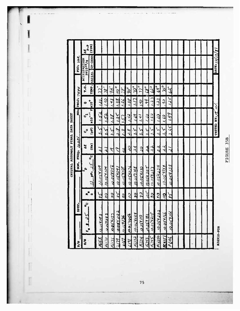
r —
I 1
*SJ « o. «w°« o. v-
V 5
< —
z o cr 1
a
£ co
HO a. 3
< J o. •J Q
•• U 0. o u
< a < 2
O a.
* [ • 0
^5 -i
0 -> NO
0
•»5 o *J t>C N« ^ r> £
;>- CO **3 0 No o a o *~t T- * oi ^ in ^~ <r t «r 'X.
a. rt "* •v -s *< *< "s. ** ^»
* N \V
u £ ^ -
CJ 1 o q V* V
\n qs vi-
vo > 3 3 NO
s CO
< Q
•4 X
v. •^ < "* ~» ** "*C to
10 Cd
0 lu u a
V, V, ^ °? Oc <* V, V, V V7 \o V
§ H Cv q
V; ir: -v, •"si 1i ••% —3 <+? T *a r T. ^ H
s a »4 M
< X «^ -4 <5- 0s 2 3 •2
1 1 ? *4 ^
u CO u CO Ok 0 <
«« s- (0 >• « -
0. >
5 Ö O
$
> I 0
a g •>- V
o
5 N o < o o s ^ 6 5 *
• K a Vn a o V 0 0, 0 r> V Q O Ol V
CJ u
>Q *. K Cx. s. S w v> DC kc <*5
ou
(0
•
"5 V
V7 5
r
1 V 0
3 >
o
0
o >
o
3 s
K • 5 5 Q 0 * ö ^ «\
's vi ^ Sfc •5 g
*<3 a », * •> •VI \n S V^ >>J o
z s ^e rs r~ 5 «^ **5 l>- > v C". vo
£ ca *e < v° . p4 vl Vj ^ < ^ < o •< « N s <
03 in ro
W OS D O
75

T—-m
I Q O x H >i >. >i
£ X X X
a a 0 a
Q w Cd w Z
§ OS Cd T *r *J" E-> V, \ V 0- m e"i m o
xxxxxxxx
aaUchllcbQiOi
>i >, X X o 0 a a w u
0) T3 EH >-i C z s -rH 0 N
3 a UJ £ E o o «3 £ £
a O
• u 01 0) <D 0) 0) o a> OJ <D i> O p» 0 co vo c C C c c o c c C c EH • r- 4J r~ r- 0 0 0 0 0 *— o 0 0 o < E-i z z z z z /\ z z z z
cn Cd .H EH u •H z z O c Cd < w o z EH r~ 0 m a\ 00 ro o r» o CN r~ fl Cl *»• •^ o CO r- r~ r» u 00 00 c* r- r~ r- r-- I» i-~ r- *> a M c 0 CM (0 £ w •H 4J •M O Cd HJ > U 05
3 O r~
iH •-H •H O r- CN
4) Q
T3
VO m
Cd
05
O EH x: c* CO to o CPi en o T i— vO o r- *r • l-i 05 u
(• C- tT >U 3 Cd *r in 00 r- 00 o o <N *r <•«"> m CN [-» a *o U > (N *~ *" c
•H •• ' *~ ^ ^ u
0) c «J
M Ch >H
U > 4J H <D 03 r- in r— t~ < w hH
i-> <3\ in h f— r~ VO 00 t— 00 t~ o 00 CN > N vu • • 3 • • • • • • • • • • T— ^r hH
C-. (0
u c 0) 3
r-
1
o i
m
0
(N
U
+ 1
in
+ en
+
m
VO
+ CM
+
in
CN
1
in
1
in
I
in
lO
+
in CO • in
EH
l-H w z
D- in r- 0) O m o CN m CN CN o CN in z >< <U • • 4J • • • • • • • • • • o
t-
H
1 1
r-
U-l (0
<D rH .Q (0
CN
1 1 1 +
in
I
in
CN
+ CN
1 1
•vr
+
CN
+
HH
Cd
Cd J-J CN w— 4J O in ^- in CM O VO o in CN u
X w • • in • • • • • • • • • • u t~ c
S +
in
+
c 3
1 I 1 +
en
+ CN
1 1
CN
+ o +
m
1
<
I
5
Cd
I
N NNNNNNNNNNNNN X XXXXXXXXXXZXZ z £££££z:£z:zs:z:£z:
m ininminminininininininin o oooooooooooco
o ooooooooooooo
Ov O>— voo^cN^rvorvvoooOv»- ^ mincii— ^t— <— »-»-cNCNCNrn r- r^r^vTivovovovovovovovovovo T ^^•^•vOvOVOVOVOVOVOVOVOVO
76

,
I Q O SB H > >. > >i >H >i >i >i > Sh > >i >, >i >i >i
£ X M X x X X X X X X X X X X X X
a a 0 a a a a 0 a a a a Q a a 0 a a a a O u Cd Cd Cd Cd Cd Cd Cd Cd Cd Cd Cd Cd Cd Cd Cd z s ex DJ EH
& s s z s z s s r I : s £ £ £ £ £
o t-H a
EH
Z 3 s s £ z z s • z I £ £ £ Z £ £ £
o £
, <D O ID 0) 0) 0) 0) © CN CN ID O o o o CM O C O c C c c c o o> o> <T\ O o o r» r~ • o r— o 0 o o 0 T— 1— »— ^- EH z A z z z z z A A A A
Ed U Z < T— •«r (N o T CO CTl i— o 00 m *— o co co o H 00 r- !— r» r- 09 r- r- o o in <— ao r~ P« CO cn •" *• "•" «— cn Cd
ocninfMoor^iniDTrcM — o> ^ ^ co CM co •-- co m vo ©
ft- • • J — voor^Trmcofl'invooo^
vo ^* co co co ^ co ^* r** r** ^*
N *— co «— o ^» «— co «g< ^ *—
I + i + + + + + + + +
in m m in in cMinor-r-mrMincMmin to T3
>t— r-TT"-«— M'cgcocooin «j c CD
+ + I I I+ + + + + + J
IT c
^o-«rcoo<— inTTCMcsvo-— -H x cn
r_ vovoinocNvococMco oouj
I I++I I i i I + + £
0)
cn c CO cn
co
^r in «- CM
co
I
in
oo
00
+
CM
m CM O
*- r-
+ +
CTi
N X
H < cn EH z
c Cd O Z
•H *m, o 4J Q b ra Cd £
•tH 3 O > Z u f M
a EH a z o
TJ o EH 01 u u u IT <0 ^ Cd «J T3 > tu C 1 <U i X > 4-1 147 fH < CO co
> CO 0> Cd M CO CO ex EH • i 3 l-l •— in O cn •" tH z
Du Cd en
co CM +
M
I Cd J Cd u <
X u
N X £
N N X X £ £
N X £
N X
N X £
N X £
N N X X £ £
N N X X £ £
N X £
N X £
N X £
N X
N X £ z
Cd T TT Tf *r ^r •V rr •^" TT ^T rr *r rr Tj- rr «T D in in in in in in in in in in m in m in in in
. * o o o o o o o o o o o o o o o o Cd ] a o o o o o o o o o o o o o o o o
1 CL
J • <
1 E-* *r in r- 0> vO 0"N o o CM CO in VO r~ o CM vo 1 ''"• co CO CO CO VO VO r» in in in in in m VO VO in • X VO VO V0 vo VO VO VO ov o> ON o> o\ 0\ o 0> ^,
• VO vO 10 vO VO VO VO vO vo vo VO vo vo VO vo r~
1 77
• •

i 1 1 1 i
r
3) -•o >
l0 0
CM 1
<*> 1 <*> ^e k U
1 * 8 § *
TO k % *>
S5 Q>5 V V V V V
V >
*! fc "}
°0 °0
T)
*3 } 2*
Öl
^0 1 *) 1 «5 0
Q % V 1 1 * x
| v
0 S

f I
' i f ,
APPENDIX I
"FURTHER DEVELOPMENTS ON SC CUT CRYSTALS"
B. GOLDFRANK A. WARNER
79
:

I
I-
FUXTHER DEVELOPMENTS OK 'SC CW CRYSTALS
Bruce Coldfrjnk and Art Warner
Frequency Electronics, Inc. New Hyde Park, N-.. lork MM
i i i
Introduction
'SC cut crystals have found their my into •any MW designs. Th« applications, though tiny •nd varied, ecnttr around the requirements of good 'g' sensitivity, resistance to radiation, fait ««up and good temperature characteristics. The temperature and attain «ffects on the 'SC cut eryatal are auch that a large Improvement over AT cut cryetala If possible. In particular, data will be given on the Improvement in radiation resistance of the 'SC over the 'AT'.
In order to produce a tuccetaful SC crystal «nit. I.e., one that tkplolta this design to the fullest, elgr.lf leant changes In design philosophy, design parameters, oaasurlng techniques, testing method«, «nd production tools must be made. Three of the »or« Important changes Involve angle control prior to final lapping, angle measurements, and frequency adjustment. Where low 'g' aanaltlvlty la Important, the crystal plates must be thermct-compreesl on bonded using small, uniform, vary precisely located mounting spots.
Orientation
That th* orientation of the plate must be closely controlled ean be understood when we consider th« typical AT frequency versus temperature curve. The center of the curve which la the Inflection point, la at room temperature, and as the specified operating taaperature goes higher, angle eeetrol become« masler. for the SC, th« inflection point la maar 100'C and as the operating temperature approaches that point the angle control becomes difficult. 70*C to SO'C •aro temperature coefficient (ZTC) for the SC cut la llfc« 40*C to SO'C for th« AT cut. At SO'C, one mlnut» of arc error cam shift the ZTC by 20*C. Th« benefit la, of cour». that once angle control la achieved the temperature curve la auch (latter.
Figure 1 «hove a quarts bar and the «tagea of •floatation, following th« UZE atandard nomenclature. TIsl t#et . Visualise a atartlng plat« «filch la a T cut, rotate it about the Z as Is by the antle « and than rotate it about lta new length, X', by th« angle thets. Th« usual illustrations chow the plat« ractangular In ahapa. The final doubly erlented plat« la usually ahown th« man« als« and ahape aa th« atartlng plate. •avavar, ana can aa« (Hat If •» errang« to aev th«
Free. »4th Ana. »req. Control lynp., OSAIXADCOH. Ft. «bmmouth. RJ 0770J, Hey 1M0.
—• 1
art aa« SHOWMC eerariOa ame ra.T msouisiD TO 'sue ac' sn«
Figure 1, Stages of Orientation for a TXwlt e6v Hank
Z »UHFACE
• -I SURFACE
'•C CUT CRYSTAL BLANK A« CUT MOM • A"
Figure 2. Quart« Hank Aa Cut Fran a V tar
80

'
I 1
I
doubly oriented platt fr cm the tar, the «tape will not be rectangular tat will ta at ehown In Figure 2. If thla wart an AT, uaual practice would ta to amply aount it In th* X-ray with tht X aale vertical and coapar« th« eryatal fact with th« aaarby 01.1 eryatal plan« at 3«" 12.7'. Hcvtvtr, with th« SC w« autt flret 'undo* th« * «Bfl*. that la tilt th« platt until the 01.1 plan« la In a «artlcal petition, Tht tilt ltttlf It not particularly critical, but now th« aountlng flat, or If you trill, th« rotation of tha platt about lta thick»«»-, tacoac* extrtacly critical, alnc« thla rotation will now tilt tht rtf«r«nc« plan«.
Our anawcr to thlt problca la to highly correct th« -X and on« Z aurfac* of th« quartt bar ltttlf tafor« cutting. Thlt la atralght forward •lnc«, of court«, th*r« art X-ray planet paralltl to that« aurfacae, Thatt highly corrtcttd •urfacaa art thtn uatd not only to orltnt th« bar In th« aaw, but alto to oriant th« blank In tht X-ray gonloacttr.
Row, which adg* aurfac« ahould we ut« for tht X-ray reference flat? Th« X' «xi» Hat in tht Z aurfacc, eoat 1'' away froa ualng th« -X aurfac* •t a rtftrtnet flat and tht X' would bt th« normal cholct.
In cither caat, the aquation to convtrt fron th« angle aeaeured by th« X-ray, to th* aptclfltd «. angl« la fairly alapl«, but It turnt out tht re la an advantag« to ualng the -X turface 1*" away from th« X' to locate tha exit about which th« X-ray «git la to ta ataeured.
Figur« 3 «how» th« ralatlonehlp bttwctn tht •pacified 6 angl« for varloua p angle*. Th« outer curve ehowt tht aquation developed by Salleto and lafratc, and the other two curvet ahow the correapondlng anglee 6 ' and 6 * aeaturtd by the tilt-back aethod for both X' wit and the -x •urfaca. V« can a*t that th« angl« aeaturtd ualng th« -X aurfac«, th« upper curv*, l» auch cloacr to tha 38* 13' rafaranec plane, «van eloatr than that of th« AT. Alao wa can aae the «lope it about 1 In f or •' trror In «Maturing t rttult« In 1' •rror In aeaaurlng 6. Tou My «j»0 havt noticed that for th« SC cut at • • 23*, that tht 14* ahlft In raf«r«nc« flat location eorraaponda to a S or 6 «J«gr«« ahlft In lndlcatad angle, or alaoot 2 to 1, Two alnutee «rror in reference flat equal» ana alnute arror la angl« aaaeureaant. To ta«p thla arror to an abaolut« ainiaua, w» aa«, a« lndlcatad aarller, th« actual corrected eurftct generated on th« quart« tar tafora It la cut. la addition w* aa« a «paclal Jig that avoid» any arror du« to chipping at tha adgee. Figure 4 ahewt the tilt tack vacuua Jig uaed «rich th« X-ray. Th« reference aurfac« aahae contact along a ltn« away fraa tha eryatal edge. Figure S ahowa thla reference, eaatact • llttl« aort clearly. Mpaatablilty aalng thla aethod j» about 10 •ecoede of arc. Th« • angle la aaaaured by a 90* tarn af tta quart« blank, la tilt la aaadad In thla «aae, tacauae tha X-ray plan« In thla petition la within 1-1/2 degreee »t fertleal, again elaaer than tta AT far thla aeaaureaent.
«•«.•.»• mm -»•.•,
Figur* 3. fttlatlonthlp Sctwtcn Sp*:lfl«C -. a-.£ Angle* and Thot* Hctturtd By Th* Tilt-lack
X-ray Method
«1 t\ •> •*«**
Figure 4. Tilt-lack Vacuua Jig Uitd With Tht Doublc-Cryttal X-ray Conloatttr
l-&&^Ä-ff
hi t
<e ©
Figur« 3. Tilt-lack Jig Showing -X Surface Contact
81

I I
I
rigur« e «how» the netting 1* acco«pll»h«d by Figur» 7 1« another view. tilt and rotation, rather that tht tilt and the rota thoac e*aeured by tha corrtctloat It» the aav tab fro« tha X-ray reedlaf •pacified 6 and » anglet, aecetaary (or the operator reading Into a pre-prograi the button.
precision eev. The a tilt and a rotation.
tee advantage of the than a double tilt le
tlon anglet are exactly X-ray. So Decenary It are directly applied
To obtain actual In practice, it la only to enter the X-ray dial ted calculator and puth
r rr • •«
Advantage« of -X Surface keferenc« and Tilt Method of Orientation
1. An «sitting double cryttal X-ray gonloneter act for AT cur can be uaed with no change other than the tilt Jig,
2. The angle it cloae «nought to 01.1 plane for calibrating of atandardt by a turnover ewt hod.
3. Orientation of the aentltlve reference flat It generated right on the quart* bar before cutting.
a. Trie i angle it deteralned without a tilt Jig and 1« alaply aetturtd by the X-ray.
3. By utlng a atandard reference cryttal, •ccuraclet of a few «econdt of arc art pottibl«.
6. There la a direct eorrctpondence between •aw table anglet and the anglet «eaturcd b> the X-ray.
7. Specified asglet are obtained eatlly by utlng • alaple prograaaed calculator.
g. The 1** p«l angle generated automatically turn« out to be the correct mounting point for the cryttal plate.
frequency Ad'u«ta«nt
The fact that the Inflection point of the SC teaperature frequency curve 1« above the operating teaperature Bake« too« teaperature frequency adjuetaent a diaatter. The alope it about 10 b per degree at 3 MHz. In addition frequency adjuttaent by circuit acant 1« Halted to about 1/* ef that of the AT. Therefore frequency edjuttaent at or Bear the teaperature at which the cryttal ta to be operated it Imperative. Figure I ahowt a aaall heater aaed In the vecuua aepotlttoe chaaher. Teaperature »anting control la by a tharalator bridge, th« lead wire« fro« tht crytttl are of apecial aatarlal and pan thru the teaperature »strolled block an their way to a aetwork which un the «aerating abate condition». Depc.iit.lon ta ay evaporation fro« a aaall tungtten fllaawnt.
Cryttal Mounting
figure f a how» «a «sat rla«ntel approach to tharao-coapreitlon (TO ribbon aovmtlng ef th« cryttal plate. Tbe ribbon ta nickel. Mi it hat a gold triangular atrip bonded tkaraon. The TC bond will w fold to gold, and tn tha ahape of a long thin rectangle, «bout 3 I JO «11«. Tfclt «et hod »trait« a better location af th« «Ountltvg point« with reapect ta tha center af the plate.* and alto per»u« TC bonding to vary thin ilitn.
Figure 6. One View of the Frecltlon S«.
Figure 7. One View of the Frecltlon Saw
Figure I. Cryttal Unit neater Far Cold Ivaperatlon in Vacuu«
I 82

I' -'"-^»•(«•I
I I r Figure 10 It • photo of on* tuch bond on a
S KHz 5th overtone plate. Figure 11 1* a drawing of a trplcal theraoeoapresslon bond. Recent dlacuaalona with and calaculatlona by Prof. Peter Lee, of Princeton University, have Indicated the extreae laportance of the mounting point« In obtaining a low 'g' aentltlvlty crystal unit. He lndlcatea a i angle near -15* as optlaua for a 3 point 90* aount. It la Interesting to note that the natural angle generated In cutting the blank, (-14.R*) which Frequency Electronics uses, the «xperlaental angle reported by Küsters, Mass, and others of Hewlett Packard In 1977, and Peter Lee's calculated angle are all essentially the ease. I believe the naturally generated angle Is the correct one, but further experimentation will be necessary with precisely aountcd units, to verify this.
Ttadlatlon Effects
An unexpected bonus caae to light when aone 24 MHz SC units In oscillators intended for uae In the Galileo Probe of Jupiter were subjected to radiation of 1.0 aegarads. The SC units changed 1 part In 1014/rad versus 2 part« in 10IJ
per rad for AT units. This is about 2 order« of •agnltude lnprovenent in radiation susceptibility. This again needs further study.
Conclusion
Figure 12 shows a graph of one 5 KHz doubly contoured SC unit Bade at Frequency Electronics, Inc. subjected to a 2C acceleration by a staple turn-over test. Plate up to plate down was 1PP101'. Rotation in the vertical plane shows less than 1PP1010 per C. Future atudles will b* alsted at Increasing the yield of auch units.
Acknowledgment
This work was supported In part by a grant fro» USAERDCOM, »DAAX20-79-C-O272.
•»••»» ewat «OLD .
• tv» sscuL. Ma» aarr
taawa
Figure •- tip.rla.nlil Cold Bond.d Nickel Mounting Ribbon
flte 1. 1 _*•*
Figure 10. Experiaentsl Therao-Cospression lor.d To A 5 KHz SC Plate
• CCvglat UM *••», lag
• li — •••
ItaTjaaM CMNI • .t*M i*C I »Mai ««a« •«' I.e..
Figure Ha Typical Thtr»o-Caaprtsslon Bond
©,©©,©©©© .©.©
Figure 12. Turn-Over T.«t of One 3> KHz, ne SC Unit Showing a ' af Last Than IPP1010
Sth Overtone SC Unit Showing a 'g' Sensitivity 3l0
I 83
—_

18 January 1982
FREQUENCY CONTROL BRANCH DISTRIBUTION LIST
Or. Bernard Sklar Aerospace Corporation MS 120-2210 Box 92957 Los Angeles, CA 90009
Dr. Charles Volk Aerospace Corporation Box 92957 Los Angeles, CA 90009
Mr. Andrew Przedpelski ARF Products 2559 75th Street Boulder, CO 80301
Mr. Hal Thicksten ASU R&D Corporation 512 North Main Street Orange, CA 92658
Mr. Robert Ellis AUSTRON, Inc. 1915 Kramer Lane Austin, TX 78758
Mr. E. J. Alexander Bell Laboratories 555 Union Boulevard Allentown, PA 18103
Mr. E.D. Kolb Bell Laboratories x
600 Mounta'in Avenue Murray Hill, NJ 07974
Mr. T. R. Meeker Bell Laboratories 555 Union Boulevard Allentown, PA 18103
Mr. Harold Jackson Bendlx Communications Division East Joppa Road Baltimore, MO 21204
I
Philip E. Aerospace Box 92957 Los Angeles, CA 90009
Talley Corporation
Mr. S. Kaat Bliley Electric Company 2545 W. Grandview Blvd. Erie, PA 16508
Mr. Kirk Dance CINOX 4914 Gray Road Cincinnati, OH 45232
Mr. Canon Bradley Colorado Crystal Company 2303 W. 8th Street Loveland, CO 80537
Dr. W. D. Beaver Comtec Laboratory 16871 Noyes Avenue Irvine, CA 92714
Mr. George Bistline 620 8elvedere Street Carlisle, PA 17013
Dr. Virgil E. Bottom 3441 High Meadows Abilene, TX 79605
Mr. Charles Stone Brightline Corp. P.O. Box 1016 Cedar Park, TX 78613
Jerry P. Middendorf Cincinnati Electronics 2630 Glendale-Milford Road Cincinnati, Ohio 45241
Mr. Larry Berberich Cirtech Corporation P.O. Box 96 15237 Cherry Street Stanley, Kansas 66223
Mr. Kelly Scott Crystal Systems, Inc. P.O. Box 225 Chardon, OH 44022

I I
Mr. Curt Bowen CTS Knights, Inc. 400 Reimann Avenue Sandwich, Illinois 60548
Mr. J.F. Silver CTS Knights, Inc. 400 Reiman Avenue Sandwich IL 60548
Mr. Hugo Fruehauf Efratom California, Inc 18851 Bardeen Avenue Irvine, CA 92715
George 0. Verdelin Eaton Corporation Elec. Inst. Div. - RSD Center 612 North Mary Avenue Sunnyvale, CA 94086
Mr. E.B. Lewis EBL Co., Inc. 91 Toll and Street East Hartford, CT 06108
Mr. William Riley EGÄG-Rubidium Clocks 35 Congress Street Salem, MA 01970
Mr. Maurice White Electrodynamics, Inc. 5625 Fox Ridge Drive Mission, KS 66201
Mr. J. J. Colbert Electronic Crystals tompany 1153 Southwest-Blvd. Kansas City, KS 66103
Mr. Donald Peters Erie Technological Products 453 Lincoln Street Carlisle, PA 17013
Mr. Carl Leonard Frequency Control Products Inc. 61-20 Woodside Avenue Woodside, NY 11377
Mr. Charles Stone Brightline Corp P.O. Box 1016 Cedar Park, TX 78613
*v
Dr. D. Emmons Frequency & Time Systems, Inc, 23 Tozer Road Beverly, MA 01915
Dr. Helmut Hell wig Frequency 4 Time Systems, Inc. 23 Tozer Road Beverly, MA 01915
Mr. Martin Bloch Frequency Electronics, Inc. 55 Charles Lindberg Blvd. Mitchel Field, NY 11553
Mr. A. W. Warner Frequency Electronics, Inc. 55 Charles Lindberg Blvd. Mitchel Field, NY 11553
Mr. Butch Tysinger Crystek Corp P.O. Box 06135 Ft. Myers, FL 33906
Mr. Jack Keres General Electric Company P.O. Box 11508 St. Petersburg, FL 33733
Mr. Thomas Snowden General Electric Company P.O. Box 11508 St. Petersburg, FL 33733
Mr. Robert Ney General Electric Company P.O. Box 11508 St. Petersburg, FL 33733
Mr. Thomas Wagner General Electric Company P.O. Box 11508 St. Petersburg, FL 33733
Technical Data Library General Electric Company P.O. Box 11508 St. Petersburg, FL 33733
Mr. Raymond H. Green Greenray Industries 840 West Church Road Mechanicsburg, PA 17055
• .

I Or. Tae M. Kwon Litton Guidance 4 Control Systems Research & Advanced Development Engineering 5500 Canega Avenue Woodland Hills, CA 91365
Mr. David L. Hessick Magnavox Gov't & Ind'l Elec Co. Advanced Products Division 2829 Maricopa Street Torrance, CA 90503
Mr. Ed Boise McCoy Electronics Chestnut & Watts Streets Mt. Holly Springs, PA 17013
Mr. Walter D. Gall a McCoy Electronics Chestnut & Watts Streets Mr. Holly Springs, PA 17013
Mr. C.E. Hagen Microsonics, Inc. 60 Winter Street Weymouth, MA 02188
Mr. J. K. Miller J.K. Miller Company 80 Wabash Street Pittsburg, PA 15220
Mr. Gene O'Sullivan Mitre Corporation MS E035 P.O. Box 208 Bedford, MA 01730 x
Dr. Myron Weinstein Mictron, Inc. P.O. Box 10126 Sarasota, FL 33578
Mr. D.R. Montgomery Monitor Products Company, Inc. P.O. Box 1966 Oceanside, CA 92054
Dr. J.F. Balascio Motorola, Inc. P.O. Box 279 Carlisle, PA 17013
Mr. Lirry Conlee Motorola, Inc. 2553 N. Edgington Avenue Franklin Park, IL 60131
Mr. L.N. Dworsky Motorola Inc. 8000 W. Sunrise Blvd Plantation, FL 33322
Mr. D. Reifel Motorola, Inc. 2553 N. Edgington Avenue Franklin Park, IL 60131
Mr. Roger Ward Motorola, Inc. 8000 W. Sunrise Blvd. Ft. Lauderdale, FL 33322
Mr. Del Gaines M-TRON Industries, East Highway 50 Yankton, OS 57078
Inc.
Mr. J. Holmbeck Nortl.ern Engineering Labs 357 Beloit Street Burlington, WI 53105
Prof. D.E. Newell Northern Illinois University DeKalb, IL 60115
Dr. L.E. Halliburton Oklahoma State University Department of Physics Stlllwater, OK 74074
Mr. N. Broadbent Ovenaire-Audio-Carpenter 706 Forrest Street Charlottesville, VA 22901
Mr. Benjamin Parzen 3634 Seventh Avenue San Diego, CA 92103
Prof. R.E. Newnham Pennsylvania State University 252 Materials Research Lab University Park, PA 16802
te^

V
I I
Mr. C. Jensik P1ezo Crystal Company 100 K Street Carlisle, PA 17013
Dr. W.H. Horton P1ezo Technology, 2525 Shader Road Orlando, FL 32804
Inc.
Prof. P.C.Y. Lee Princeton University Oept. of Civil Engineering Princeton, NJ 08540
Mr. H. Phillips Q-Tech Corporation 2201 Carmelina Avenue Los Angeles, CA 90024
Daryl Keeper QUARTZTEK, Inc. 20 South 48th Avenue Suite 2 Phoenix, AZ 85043
Mr. T.E. Parker Raytheon Research 28 Seyon Street Waltham, MA 02154
R. Michel Zilberstein Raytheon Company Microelectronics Dept. 465 Centre Street Quincy, MA 02169
Mr. F. Brandt \ Reeves Hoffmao Division 400 W. North Street Carlisle, PA
Mr. D.V. Kingery Reeves-Hoffman 400 W. North Street Carlisle, PA 17013
Prof. H.F. Tiersten Rensselaer Polytechnic Inst. Jonsson Engineering Center Troy, NY 12180
Mr. E.J. Staples Rockwell Science Center 1049 Camino Dos Rio Thousand Oaks, CA 91360
Mr. Marvin Frerking Rockwell International Collins Tele. Prod. Div. 855 35th Street, N.E. Cedar Rapids, IA 52406
Mr. J.M. Ronan J.M. Ronan Assoc,, 44 Cindy Lane Wayside, NJ 07712
Inc.
Mr. T.J. Young Sandia Laboratories P.O. Box 5800 Albuquerque, NM 87185
Mr. Jack Saunders Saunders & Assoc. 7440 E. Karen Drive Scottsdale, AZ 85251
Mr. O.E. Lussier Savoy Electronics Company P.O. Box 5727 1175 NE 24th Street Ft. Lauderdale, FL 33334
Dr. D. Kinloch Sawyer Research 35400 Lakeland Blvd. Eastlake, OH 44094
Dr. B. Sawyer Baldwin Sawyer Crystals, Inc. P.O. Box 96 Gates Mills, OH 44040
Mr. J. H. Sherman 2022 Woodcrest Drive Lynchburg, VA 24503
Mr. Herbert Rogall Singer 90 New Dutch Lane Fairfield, NJ 07006
-

1
I
I I
Or. E. Hafner 881 Sycamore Avenue Tinton Fall, NO 07724
Mr. Joseph H. Geiger Hazeltine Corp. Greenlawn, NY 11740
Or. Donald Hammond Hewlett-Packard Company 1501 Page Mill Road Palo Alto, CA 94304
Mr. C.A. Adams Hewlett-Packard Company 5301 Stevens Creek Blvd. Santa Clara, CA 95050
Mr. Mike Fisher Hewlett-Packard Co. 5301 Stevens Creek Blvd. Santa Clara, CA 95050
Mr. U.A. Küsters Hewlett-Packard Company 5301 Stevens Creek Blvd. Santa Clara, CA 95050
Mr. Robert Birrell P.R. Hoffman Company 321 Cherry Street Carlisle, PA 17013
Or. T.R. Joseph Hughes Aircraft Company Bldg. 600/F259 P.O. Box 3310 Fullerton, CA 92634
Mr. H. E.. Oil.lon Hughes Aircraft Company 500 Superior Avenue Newport Beach, CA 92663
Lloyd C. Tignor Isotemp Research, Inc. ' P.O. Box 3389 Charlottesville, Virginal
Mr. J. Erasmus JAN Crystals Co. 2400 Crystal Drive Ft. Myers, FL 33907
22901
Dr. Terry M. Flannagan JAYCOR 11011 Torreyana Road P.O. Box 85154 San Oiego, CA 92138
Dr. Richard L. Sydnor Jet Propulsion Laboratory MS238-420 4800 Oak Grove Drive Pasadena, CA 91109
Mr. J. Norton Johns Hopkins University Applied Physics Laboratory Johns Hopkins Road Laurel, MD 21810
Mr. Lauren J. Rueger Johns Hopkins University Applied Physics Laboratory, 4- Johns Hopkins Road Laurel, MD 20810
326
Mr. Rolf Ueglein Hughes Aircraft Missile Systems Group 8433 Fallbrook Avenue Canoga Park, CA 91304
Mr. Robert Kern KERNCO, Inc. 28 Harbor Street Danvers, MA 01923
Mr. Richard Bush MIT Lincoln Laboratory P.O. Box 73 Lexington, MA 02173
Mr. Lewis D. Collins MIT Lincoln Laboratory P.O. Box 73 Lexington, MA 02173
Mr. Paul McHugh MIT Lincoln Laboratory P.O. Box 73 Lexington, MA 02173
Mr. William C. Lindsey Lincom Corporation 1543 Olympic Blvd 4th Floor- Los Angeles, CA

ADA132 274 VIBRATION RESISTANT QUARTZ CRYSTAL RESONATORS(l) FREQUENCY ELECTRONICS INC MITCHEL FIELD NY B GOLDFRANK ET AL. NOV 82 DELET-TR-79-0272-F
UNCLASSIFIED DAAK20-79-C-0272 F/G 9/1

1.0 iS*- IM ^= «* B- 12.2
I.I
11.25 i 1.4
2.0
1.6
MICROCOPY RESOLUTION TEST CHART
NATIONAL euftCAU Of $T*N0*»D5 - i»*3 - A
I .1 f ' 1 \
MMM>

•^—-
Mr. T. Sokol Sokol Crystal Products, Inc. 121 Water Street Mineral Point, WI 53565
Mr. Jürgen H. Staudte 391 S. Henning May Anaheim, CA 92807
Mr. W.J. Tanski Sperry Research 100 North Road Sudbury, MA 01776
John Fisher Standard Crystal Corp 9940 Baldwin Place El Monte, CA 91731
Or. Shih S. Chuang STATEK, Inc. 512 North Main Street Orange, CA 92668
Mr. L.T. Claiborne Texas Instrument Co. P.O. Box 225936 Dallas, TX 75265
Mr. William F. Donnell Tracor, Inc. MS 6-1 6500 Tracor Lane Austin, TX 78721
Mr. F. Sauerland Transat Corporation 3713 Lee Road Shaker Heights, OH 44120
Or. Reynold Kagiwada TRW DSSG Rl, 1086 One Space Park Redondo Beach, CA 90278
Mr. M. Gilden United Technology Res. Ctr. Silver Lane E Hartford, CT 06108
Mr. Neil Bernstein ^ Valpey-Flsher Company 75 South Street Hopkinton, MA 01748
Mr. N. Benoit VALTEC 75 South Street Hoplngton, MA 01748
Mr. Stanley Tulgan Vectron Laboratory Inc. 166 Glover Avenue Norvwlk, CT 06850
Mr. E.E. Simpson Western Electric 1600 Osgood Street N. Andover, MA 01845
i'1r. Ivan Oak Western Electric 1600 Osgood Street N. Andover, MA 01845
Mr. D.J. Healey III West'nghouse Inc. P.O. Box 746, MS 294 Baltimore, MD 21203
Mr. David Larson Sawyer Crystal Systems Inc. 1601 Airoort Road P.O. Box 2707 Conroe, TX 77301
Mr. B.R. McAvoy Westinghouse R&D 1310 Beul ah Road PUtsburg, PA 15235
LT Karl Kovach YEE AF Space Division P.O. Box 92960 Worldway Postal Center Los Angeles, CA 90005
CPT Demo Galanos USAF Space Division, YEZ P.O. Box 9260 Worldway Postal Center Los Angeles, CA 90009
r
MM MM -- - 2

I Mr. A.F. Armington USAF RADC/ESM Hanscom AFB Bedford, MA 01731
Dr. P.H. Carr USAF RAOC/EEN Hanscom AFB Bedford, MA 01731
Mr. A. Kahan USAF RAOC/ES Hanscom AFB Bedford, MA 01731
Or. N. Yannonl USAF RADC/ESE Hanscom AFB Bedford, MA 01731
Mr. J. Plaisted ASD/XRQ-NIS Wright Patterson AFB, OH 45433
Or. A. Ballato USAERAOCOM ATTN: DELET-MA-A Fort Monmouth, NJ 07703
Mr. R. J. Brandmayr USAERADCOM ATTN: DELET-MQ-R Fort Monmouth, NJ 07703
Dr. R.L. Filler USAERAOCOM ATTN:- OELET-MQ-R Fort Monmouth, NJ 07703
Mr. V.G. Gelnovatch USAERAOCOM ATTN: DELET-M Fort Monmouth, NJ 07703
Mr. J.6. Gualtieri USAERAOCOM ATTN: DELET-MQ-R Fort Monmouth, NJ 07703
Mr. J. Koslnski USAERADCOM ATTN: DELET-MQ-R Fort Monmouth, NJ 07703
Mr. T. Lukaszek USAERADCOM ATTN: DELET-MA-A Fort Monmouth, NJ 07703
Mr. G. Malinowski USAERADCOM ATTN: OELET-MQ-O Fort Monmouth, NJ. 07703
Mr. V. Rosati USAERAOOM ATTN: DELET-MQ-0 Fort Monmouth, NJ 07703
Mr. S. SchodowsM USAERADCOM ATTN: DELET-MQ-0 Fort Monmouth, NJ 07703
Dr. J.R. V1g USAERADCOM ATTN: DELET-MQ Fort Monmouth, NJ 07703
Mr. W. Washington USAERADCOM ATTN: DELET-MQ-R Fort Monmouth, NJ 07703
USDOE Technical Information Center P.O. Box 62 Oak Ridge, TN 37830
Mr. Andrew Ch1 Code 810 NASA/GSFC Greenbelt, MD 20771
Mr. F.L. Walls National Bureau of Standards 32S Broadway Boulder, CO 80303
y=

~1
<
I i
--
Mr. David Philips Naval Research Laboratory Code 7524 4555 Overlook Avenue SW Washington, DC 20375
Dr. Gernot Winkler US Naval Observatory 34th & Massachusetts Ave, NW Washington, DC £0390
Mr. Ralph Allen Naval Electronic Sys Command Code 51023 Washington, DC 20360
Dr. Allan Tarbell PM SOTAS DRCPM-STA-TM Fort Monmouth, NJ 07703
Mr. Cary Flshman PM SINCGARS ORCPM-GARS-TM Fort Monmouth, NJ 07703
r li
I1
r r


![Microcopy: a taxonomy and synthesis of best practices · Microcopy can alleviate a user's potential concerns [1]. Like instructional microcopy, concern alleviators can be used to](https://img.pdfslide.us/doc/110x75/60b2dae745235b5cb9229295/microcopy-a-taxonomy-and-synthesis-of-best-microcopy-can-alleviate-a-users-potential.jpg)