Embed Size (px)
Citation preview

J. Construct. Steel Research 29 (1994) 71-94
Hysteretic Behaviour of Steel Members: Analytical Models and Experimental Tests
JoS.o Azevedo & Luis Calado
CMEST, Department of Civil Engineering, lnstituto Superior T6cnico, Av. Rovisco Pais 1, 1096 Lisboa Codex, Portugal
A B S T R A C T
The seismic performance of steel structures is highly dependent on the hysteretic behaviour of their members. The assessment of this behaviour can be done by means of experimental tests and the use of analytical models that take into account the main phenomena involved in a non-linear response. An overview of experimental methodologies for cyclic tests, including a more detailed investigation of the ECCS recommendations, is presented. Analytical models for the simulation of hysteretic behaviour and comparisons with some experimental results are shown. Finally, it is demonstrated how a cumulative damage model for failure assessment allows for the evaluation of q factors for structural design.
1 I N T R O D U C T I O N
The seismic response of a structure is highly dependent on the ability of its members to dissipate energy by means of hysteretic behaviour. As steel is a very ductile material, the performance of steel structures depends, among other aspects, on a choice of member characteristics to avoid problems like global and local buckling, fracture and low cycle fatigue.
In order to fully understand the hysteretic behaviour of structural members it is necessary to perform experimental tests on a range of different types of elements. The results of such experiments can give some insight into the problems arising from the cyclic behaviour and may be employed to calibrate analytical models developed for the same purpose. The combined use of experimental and analytical results should allow for the correct characterisation of the hysteretic behaviour of steel members up to collapse.
71 J. Construct. Steel Research 0143-974X/94/$07.00 ~) 1994 Elsevier Science Limited, England. Printed in Malta

72 J. Azevedo, L. Calado
On the other hand, a criterion to define collapse is fundamental as it makes possible the evaluation of the corresponding level of seismic loading and, thus, by comparison with the response values obtained by means of linear structural analysis, allows for the quantification of coefficients that can be used to transform the values of certain variables obtained from linear analyses into the values of the same variables that would be obtained by means of a non-linear analysis.
2 O V E R V I E W O F E X P E R I M E N T A L M E T H O D O L O G I E S
The cyclic behaviour of steel members can be studied on the basis of the different methodologies employed to impose cyclic loading. The most commonly used method individual members or which has been widely
is the quasi-static imposition of cyclic loads on structural subassemblages. This methodology, applied all over the world in the last decade,
provides information on the hysteretic behaviour of the element, namely its ductility, strength and energy dissipation capacity. This procedure, which does not require expensive equipment, can be applied to small or real sized structural elements while only simple test operations are involved.
Methodologies which utilise shaking tables ~ are mainly employed to study scale models and for research on the behaviour of a particular structural element or in the comparison of different solutions of the same structural element. In spite of producing a more accurate reflection of reality, shaking tables require sophisticated equipment and involve high capital and operation costs.
The pseudo-dynamic methodology 2 provides another possibility for imposing cyclic histories on structural elements or scale models. This method is an on-line computer controlled technique that combines physi- cal measurements and numerical analysis to simulate the seismic behav- iour of scale models, subassemblages or structural elements. It has various advantages as compared with shaking tables, namely, the possibility of using full-scale test specimens without taking into account dynamic similitude, allowance for detailed observation of the specimen during the test and much lower costs of equipment, installation and operation. In spite of receiving widespread interest there have been only a few ap- plications concerning the cyclic behaviour of steel members.
Cyclic loading imposed in a quasi-static way is, thus, the most common- ly used methodology to study the cyclic behaviour of steel members and it is especially suitable for parametric studies or to compare different

Hysteretic behaviour of steel members 73
solutions regarding a structural member. In this methodology, the loading conditions used in tests 3 5 vary from one researcher to another, but commonly consist of displacement increase with full deformation reversals. In addition, however, experimental tests with no force reversal, with force reversal but no deformation reversal, with partial or full deformation reversals and random cyclic loading, can be found in the literature.
Loading histories mainly consist of displacement increments rather than of load increments because in the case of buckling or fracture a sudden force decrease will occur and test control will become difficult. Employ- ment of full deformation reversals receives its justification from the fact that it is the situation that best represents the seismic behaviour of elements. The type of reversal used in the tests should consider that the element is part of the whole structure and is designed to resist both static and seismic actions. To avoid low cycle fatigue phenomena, the number of cycles at a given maximum displacement is usually defined to ensure that the number of repetitions of constant amplitude is not too high, and is compatible with the number of high peaks of displacement caused by real earthquakes, which is generally low.
The equipment employed in this testing procedure is usually vertical and consists of a supporting girder, to which the specimen is bolted. The top flange usually has a double row of holes to allow different mounting positions of the element and when necessary the use of a power screwjack. A reaction frame composed of one column and inclined truss is necessary to fasten the main power screwjack. Usually, the column is a H profile with two rows of holes to allow different jack positions. To prevent out-of-plane specimen deformation, a lateral bracing system can be used. The testing equipment described is the testing apparatus available at the Politecnico di Milano 6 where some experimental tests of steel members were performed, and at the Instituto Superior T6cnico of Lisbon.
Using the above mentioned and similar testing equipment, tests per- formed on bracing elements 4'7 using displacement control with deforma- tion reversals, have shown, as can be seen in Fig. 1, that after the initial buckling, the load-carrying capacity of the brace rapidly decreases and is accompanied by yielding of the section at midheight of the brace. In subsequent cycles a reduction in the buckling load capacity is observed, as shown in Fig. 2 which displays the failure mode for the same element.
This reduction can be attributed to the residual lateral displacement at the midheight of the brace. The Bauschinger effect appears in the reduc- tion of the steel's tangent modules due to the severe stress reversals. The hysteretic behaviour of the brace is affected by its slenderness ratio. Braces with small slenderness ratio generate fuller, more rounded curves than

74 J. Azevedo, L. Calado
F (kN)
F - '= = 300
52Lx 80x 80x 8 ~, = 145
200
-40 I t 2 P I ~ I 20 40 8 (mm)
- 500
Fig. 1. Cycl ic b e h a v i o u r o f a brace e lement .
Fig. 2. Fa i lu re m o d e o f a b race e lement .
more slender braces and consequently absorb more energy. In general, bracing elements with larger slenderness ratios show more rapid deterior- ation in their compressive bearing capacity. The cross-sectional shape can also affect the cyclic behaviour of the brace. This parameter is related to

H ysteretic behaviour of steel members 75
the brace's susceptibility to lateral-torsional and local buckling and, consequently, to its compressive-carrying capacity. In general, current steel rolled sections exhibit local buckling at extremely large lateral displace- ments. Experimental studies performed by several authors indicate pro- gressively poor performances of the following cross sectional shapes: tubes, wide flanges, tee, double channels and double angles.
Another structural element whose cyclic behaviour has been inves- tigated using this methodology is the beam element. 5,a Experimental results have shown that the occurrence of local buckling in the flanges does not signal an immediate loss of the carrying-moment capacity. This can be attributed to the considerable post-buckling strength of the plate elements. However, after the occurrence of the maximum load in the following cycles, the moment capacity deteriorates as shown in Fig. 3.
F ( k N )
125- cross section
F
(mm) T
- 8 0 - 6 0 60 80 ~ (ram)
- 1 2 5 -
Fig. 3. Cyclic behaviour of a beam.

76 J. Azevedo, L. Calado
Fig. 4. Failure mode of a beam element.
This deterioration increases with the width-thickness ratio of the flange as a consequence of an early occurrence of local instability in the flange elements as shown in Fig. 4. The severe distortions of the flanges tend to induce torsional displacement of the section producing a lower load than would develop in pure flexural buckling.
These severe distortions also produce an axial shortening of the beam. For cantilever beams, plastic hinges extend up to a distance equal to the lower dimension of the cross-section. This accounts for the procedure usually adopted in the plastic design of steel structures.
Shear links are other type of structural elements that have undergone investigation mainly in the US. 9 Experimental tests using quasi-static

Hysteretic behaviour of steel members 77
cyclic loading have shown that their behaviour is strongly dependent on their length. If this is sufficiently long, plastic moment hinges form at both ends of the link. On the other hand, if the link is short, it tends to yield in shear with smaller end moments. Shorter active links will yield predomi- nantly in shear, and are called shear links. Those that are somewhat longer have a good deal of moment-shear interaction. The end moments of the long links will approach the plastic moment capacity of the beam, and moment hinges will form at the ends of the links. Such links are referred to as moment links.
For moment links, a large increase in shear capacity can take place with only small change in moment resistance. Conversely, for shear links the shear capacity remains essentially constant for a considerable range of end moments.
3 E C C S R E C O M M E N D A T I O N S F O R T E S T I N G P R O C E D U R E S
The procedure for assessing the behaviour of structural steel elements under cyclic loads recommended by the European Convention for Con- structional Steelwork, (ECCS) ~° can be applied to plane or three-dimen- sional tests and may include preliminary monotonic displacement tests or obviate them. If they are included, the methodology is termed a complete testing procedure (requiring three specimens, two for the monotonic test and one for the cyclic test) otherwise it is called a short testing procedure (it needs only one specimen for cyclic test). Due to economical reasons, the second procedure is preferable.
Regarding the short testing procedure, due to the lack of knowledge at the beginning of the test about the reference elastic load (F~- ; F~- ) and the reference elastic displacement (6r+; 6; -), it is necessary to perform steps of displacement sufficiently small to ensure that at least four levels of displacement are imposed before the reference elastic displacement is reached. In this procedure the reference elastic load (F~ ; F i ) is defined as the interception between the tangent modulus (Et + ; E~- ) at the origin of the force-displacement curve evaluated from the first cycle and the tangent to the envelope curve of the cycles with a slope of 10% of the initial tangent modulus as indicated in Fig. 5.
As soon as the reference elastic limits are defined, three cycles in the interval [-(2 + 2n)6 + ; (2 + 2n)6~ ] with n = 0, 1, 2, 3.. . are imposed. The end of the test is left free, however, the test should proceed as far as possible in order to obtain the maximum information.
78 J. Azevedo L. Calado
Fy
Et Et/l 0 ~-
Fig. 5. Definition of the reference yield limits.
Regarding the interpretative parameters of the testing procedure, several problems are raised when it is necessary to compare different test results, or to make a synthesis of a test, due to the diversity of its interpretative parameters.
The ECCS recommendations seek an uniformisation of the interpreta- tive parameters which are established in ratios with understandable meaning for the engineer. The suggested parameters are defined by assuming as a reference the perfect elasto-plastic behaviour, implying that all the ratios are equal to one for that particular kind of behaviour.
Due to the possible different behaviour of the element in the tension and compression ranges, the parameters are evaluated in both of these ranges. The quantities used in the ratios are deduced from the force-displacement curve and are obtained for cycles with displacements larger than the reference elastic displacement as shown in Fig. 6.
The proposed control parameters for a typical cycle are as follows:
• full ductility ratio:
• resistance ratio:
F + F7 e+ = F-~ e/- = F

Hysteretic behaviour of steel members
F F + Y A8 i
. . . . . T
Elasto plastic behaviour////
8- ' / . ;: '
il / / ~ ? ~ J ~ ' / / ~ , ~ Real behaviour • / / / / / / / / , . . . . . / , ,111 ~ I
AS] F )
79
Fig. 6. Control parameters in a general cycle.
• rigidity ratio:
M - tg<~ M - tg~i- tg~7 tg~;-
• absorbed energy ratio:
A + Ai- r//+ = (M + 6/- -- 6~- -- 6~- )F~- rh- = (6f + 6 + -- 6~- -- 6y + )F~-
where
6,+(6, - )
6 ; (6>:)
a67 ( a a / )
F + (FF)
F ; (F 7 )
tg~+ (tg~F)
tg~ 7 (tg~_~ )
is the value of the max imum positive (negative) displace- ment in the ith cycle; is the value of the positive (negative) reference elastic displacement; is the value of the max imum displacement in the positive (negative) force range in the ith cycle; is the value of the positive (negative) force corresponding to the 6~+(& - ) in the ith cycle; is the value of the positive (negative) reference elastic force; is the value of the slope of the tangent to the force- displacement curve when F changes from negative (posi- tive) to positive (negative) at the ith cycle; is the value of the slope of the tangent at the origin of the force-displacement curve when it increases in the positive (negative) side; and
80 J. Azevedo, L. Calado
£ 1 • ,t
+ +
I " - . I . + +
~t ~t
Fig. 7. Example of the interpretative parameters for a general test.
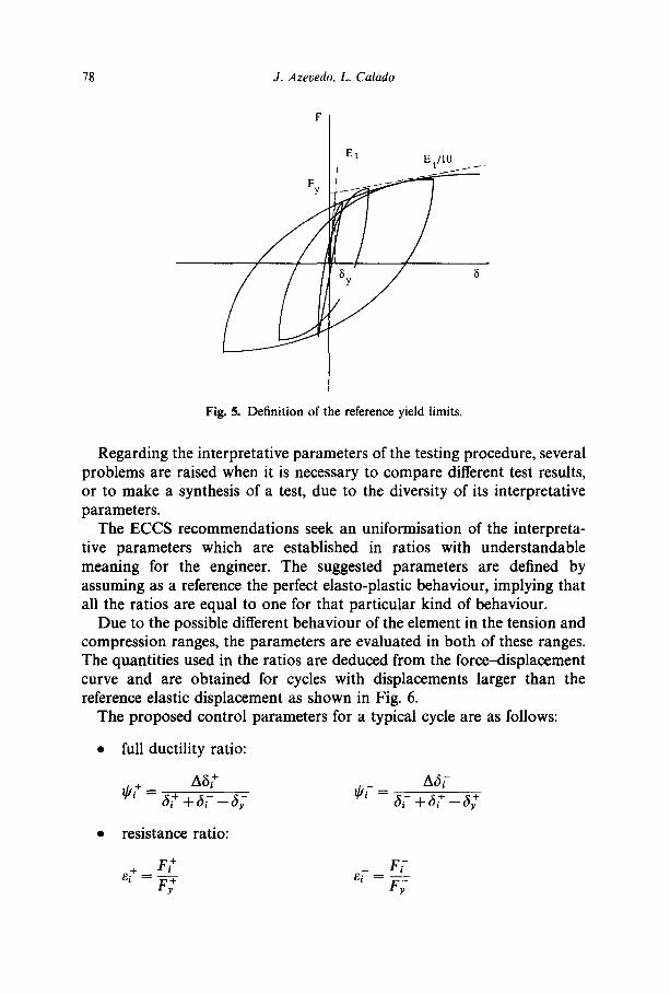
A~-(Ai-) is the area of the positive (negative) force range half cycle in the force-displacement curve.
For each group of three cycles of equal displacement, the above parameters are defined as a function of the ductility (#) (ratio of the current displacement to the reference elastic displacement (#= 6/6y)) by means of the variables ~k+(#+), ~-(p~-), e+(p+), ~:-(/-C), ~+(p+), ~-(pT), ~/+(p+), ~/-(/~F) which are evaluated as the minimum value of the corresponding control parameters, namely ~ +, ~ - , e +, e-, ~ +, ~-, r/+ and ~/- evaluated in each cycle in a group of three.
The test is then characterized and resumed by these values which represent discontinuous functions. In Fig. 7 these functions are represented for a general test.
In general, the hysteretic behaviour of the element improves as its behaviour becomes closer to the reference perfect elasto-plastic behaviour (values of these functions near one). Small values of these parameters ( ,~ 1) may be assumed as an indication of the end of the test due to a large loss of ductility, resistance, rigidity and energy dissipation capacity.
The parameters proposed by the ECCS, being a uniform method of comparing tests performed for different structural members and carried out in different laboratories, have the advantage of being efficient in the quantitative analysis of the cyclic behaviour of structural elements and can also be considered as practical parameters to define code acceptance criteria.
4 A N A L Y T I C A L M O D E L S F O R H Y S T E R E T I C B E H A V I O U R
Several analytical models have been developed to represent the cyclic behaviour of steel elements. These models can be divided into three

Hysteretic behaviour of steel members 81
different main types: finite elements, phenomenological models and physi- cal theory models.
The finite element approach generally subdivides the member into a series of segments, each of which may be subdivided again into a number of elements. Studies performed by Hancock 11 on the interaction between local and lateral buckling of I beams applied this type of numerical model. However, in spite of providing the most realistic representaton of the element behaviour, the finite element method usually demands too much computing time for the practical analysis of steel elements.
Phenomenological models based on simplified hysteretic rules which only mimic the observed force-displacement curves of the element are currently the most common approach to the analysis of steel elements.
Maison and Popov 3 developed an algorithm for the simulation of the cyclic behaviour of braces as shown in Fig. 8.
This algorithm idealises the brace as a truss bar that mimics the experimentally observed hysteretic behaviour by means of piecewise linear approximations. This linearity is very important for dynamic analysis because it implies that a solution does not require excessive computer time, allowing extensive parametric studies to be performed. The features of this model take into account the maximum compressive load reduction with consecutive inelastic cycles, and the inelastic lengthening of the element, which is assumed to depend on the amount of the inelastic shortening in the preceding cycle. The results obtained with this model agree reasonably with the experimental tests in the case of slender braces in which the phenomenon of local buckling is not pronounced.
F
F F y Fig. 8. Phenomenological model for hysteretic behaviour of a brace.

82 J. Azevedo, L. Calado
The use of such models requires that numerous empirical input par- ameters be specified for each analysed element. It is difficult to select these parameters properly without access either to appropriate experimental results or, alternatively, to analytical results obtained using other, more refined, models. For these reasons, phenomenological models are often restrictive in their applicability.
Physical theory models incorporate simplified formulations based on physical considerations that allow the cyclic inelastic behaviour to be computed. Unlike the prior empirical information on cyclic inelastic behaviour required for phenomenological models, the input data for physical theory models are based on the material properties and common geometric properties of a member. Moreover, the geometric representation of the element is considerably simpler than that used for a finite element model. One of the first physical theory models was developed by Higgin- botham and Hanson 12 to represent the cyclic behaviour of braces.
Usually, physical models to simulate the cyclic behaviour of steel elements, bracing systems or beam-columns, consist of elastic or rigid bars connected by a deformable 'cell'. The plastic state of the cell is described by an interaction curve relating the fully plastic moment and axial force at the plastic cell, as in the Ikeda and Mahin 13 or Toyama 14 models, or have lumped mechanical properties as in the Ballio and Perotti 7 or Calado 8 models. The end conditions for bracing systems are in general of two types; either pinned-pinned or fixed-fixed, while for beam-columns the end conditions are fixed-free or fixed-fixed.
The stress-strain relationship of a material is usually assumed as elasto-plastic with kinematic hardening. As shown by Castiglioni, 15 this type of constitutive law, when compared with other more complex laws, like Giuffr6-Menegotto-Pinto or Ramberg-Osgood, gives good results without requiring excessive computing time.
The model developed by Ballio e t al . 7 for diagonal bracing has two elements connected by an elasto-plastic cell as shown in Fig. 9.
The equivalence between the model and the diagonal bracing is imposed in the elastic range by equating the critical load and the bending moment in the cell at the elastic limit. At the end connections of the diagonal bracing, the effects due to joint slippage and hole ovalisation are consider- ed. The elasto-plastic cell can also take into account the effects of local buckling, fracture and low-cycle fatigue. Local buckling is modelled using the concept of variable effective widths from plate theory while the strain energy density criterion proposed by Sih and Madenci 16 is used to simulate fracture. Low-cycle fatigue is modelled using Miner's rule. ~ 7 The comparison between numerical results (Fig. 10) and experimental tests

Hysteretic behaviour of steel members 83
NI5
] elasto_pla~i~,:~ll ~-~) !
/.I" /
/
/ / /
/ /
J Stress-strain diagram
Cross sections of the "cells" llll[lllllllll q i l l l l l
IIIII!111111
Fig. 9. Physical theory model for hysteretic behaviour of a brace.
F (kN)
F -~--~¢ ~-.~-~ 300
52Lx 80x 80x 8 ~. = 145
20O
- 40 I ~2~) I I I ) ~ / 20 40 8 (mm)
- 500
Fig. 10. Numerical simulation of the cyclic behaviour of a brace element.

84 J. Azevedo, L. Calado
cross section
F -e2oo
(mm) L
F (kN)
125
-80 -60 I-4P I - ~ llft |l |H gO I 140l 60 80 8(mm)
Fig. l l . Numerical simulation of the cyclic behaviour of a beam.
(Fig. 1) indicates a good agreement over most of the loading ranges (errors less than 10%) either in terms of the force-displacement or in terms of resistance, ductility and energy dissipation.
The physical model for beam-columns develop by Calado et al. 5'a is similar to the model developed by Ballio for bracings. The rigid bar is assumed to be initially straight and displacements cause bending about a principal axis of the cross-section. Shear deformation is disregarded. The numerical results (Fig. 11), when compared with the experimental tests (Fig. 3) in terms of the parameters suggested by the ECCS recommenda- tions for testing procedures, always show errors smaller than 8%.
At the present time it appears that physical theory models provide a promising method for representing the cyclic inelastic behaviour of steel
Hysteretic behaviour of steel members 85
elements, since they combine the realism of finite element approaches with the computational simplicity of phenomenological modelling.
5 C U M U L A T I V E D A M A G E M O D E L S F O R F A I L U R E A S S E S S M E N T
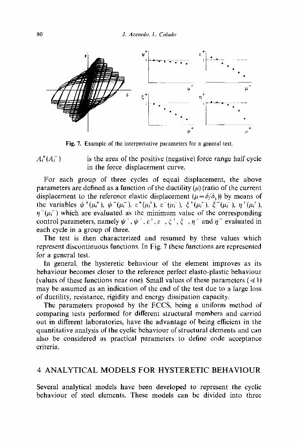
When a ductile material or structural member is subjected to cyclic loading it can be assumed that, for each cycle which exceeds a certain amplitude, the material or member will have diminished its ability to withstand further loading. These changes in performance may not be visible in the early stages, but correspond to a progressive process of damage accumulation that may eventually lead to collapse.
This concept, which was first introduced to explain metal fatigue problems Iv has been extensively used to explain the process of damage accumulation in steel members subjected to cyclic loading.
Several authors have dealt with this problem making the basic assump- tion that there is a number of cycles, N I, of constant amplitude, having plastic deformation Alp, which lead to failure and that these two par- ameters are related by the following equation:
N f = C - ~(A6r) -c (1)
where C and c are parameters related to the structural behaviour. If one admits the hypothesis of linear damage accumulation (Miner's
rule) the damage for each cycle of plastic deformation is liNe, and thus the accumulated damage after N cycles of different amplitude may be given by the following equation:
i N - I , = C . ( A a p , ) c (2)
The amplitude of the plastic deformation can be measured in terms of displacements, deformations, curvatures, dissipated energy or any other quantity that may be linked to the nonlinear behaviour of the element. It is advisable that the value of this quantity be normalised to its corresponding value at yield level and thus relates to ductility. In this case, the damage value corresponding to collapse should also be assumed normalised to the same quantity and related to the same measure of plastic deformation.
The process of damage accumulation is obviously related to the behav- iour of the element when subjected to cyclic loading and the path to

86 J. Azevedo, L. Calado
collapse depends on the phenomena involved in the response, such as global and local buckling, fracture and low cycle fatigue.
The assessment of damage accumulation can thus be made through an interpretation of the numerical simulation or experimental results and provides an additional method of performing a calibration of numerical models of structural behaviour based on experimental tests.
Different damage accumulation models have been used in recent re- search studies and are essentially all phenomenological models based upon experimental data.
Park et al. 18 have assumed a model in which damage accumulation depends on both the dissipated hysteretic energy and the maximum response deformation. This model is more suited for concrete structures but has also been adopted to describe the behaviour of steel elements. Krawinkler et al.19 assumed a simpler model where damage accumulation is dependent only on the cumulative amplitude of the inelastic defor- mations and has proved to be suited for steel structures.
The authors have developed a similar model that not only takes into account this accumulation, but can also make the level of damage accumulation dependent on the order of the cycle, with the first cycles having a larger contribution to the overall damage. This model of damage accumulation 2° is represented by the following equation:
N c .°(A6M D= c 2_,z - - (3)
,
where i is the order of the cycle, a is a coefficient related to the importance of the order of the cycle (a ~< 0) and A6y is the yield deformation amplitude and the other parameters have the same meaning as in eqn (2). To calibrate this empirical model, parametric tests were conducted on the results of a series of numerical simulations of the structural response of steel members subjected to different loading histories. These tests showed that values of c = 1 and a =0 corresponded to the simulation of damage accumulation more consistent with attaining collapse for the same damage value D for the different loading histories. This allows for the conclusion that damage at collapse does not seem to be dependent on the order of the cycles, appearing to be the result of a linear accumulation process.
To predict the failure of structural members based on the above mentioned damage accumulation model, it is necessary to define a failure criteria that can be used for any loading condition. Failure of a structural member can be viewed as the reaching of a limit stage, usually defined in terms of the attainment of a given ductility, or a decrease below a certain

Hysteretic behaviour o f steel members 8 7
strength value, equivalent stiffness or capacity to dissipate energy. Usually this limit stage has to be calibrated based on experimental evidence of collapse and should be defined in stochastic terms if a probability of failure is sought. The authors have defined the criterion that assumes failure to occur when the normalised hysteretic energy (r/) for a given cycle falls below a level, assumed to be 50%. 20 The normalised hysteretic energy is evaluated as the ratio of the dissipated energy for a given cycle to the energy that an elasto-plastic system would dissipate for the same deforma- tion amplitude. The process of evaluation of the damage index at collapse is shown in Fig. 12, which represents for all the response cycles of a single structural element submitted to a large number of different loading histories, the relationship between the damage index (D) and the nor- malised dissipated energy (q). This 50% criterion proved to be reliable due to the fact that, regardless of the adopted loading history, the decrease in the capacity to dissipate energy occurs in a sudden fashion (typically, in one or two cycles the normalized hysteretic energy may fall from values close to 100% to very low values) and always occurs for a very low range of the damage values defined in eqn (3). Moreover, the evidence gathered from experimental studies also supports this criterion.
The use of the damage accumulation model and criterion for collapse allows for the adoption of a very important concept. It is possible, for a given cross section of a structural member, to define a damage index which depends only on the section's properties and the initial strain level and that fully characterizes its ability to dissipate energy and thus its hysteretic behaviour. This damage index can also be used to predict collapse in numerical simulations of the member's structural response.
The choice of structural members to sustain large deformations under seismic loading has to be made in terms of their ductile characteristics. A structural member with a high damage index, is a member which can sustain larger deformations and is able to dissipate more energy up to
n
1 . 5 0 ,
1 . 0 0 .
0 . 5 0 -
0 . 0 0
0 25 5 0 7 5 1 0 0
F i g . 1 2 . E v a l u a t i o n o f d a m a g e i n d e x a t c o l l a p s e .
I I I I I 1 I P E 3 0 0 I I I N / N c r = 0 . 0 0
~ _ ~-- _ _ _ F e 3 6 0
I I I k = 7 5
I I I I
I I I ~ I . . . . ~_ . . . . ~ . . . . . I-- _ - - - - "~ t~ £ . . . . .
I I I I " ~ , . . . . I . . . . I . . . . 1 D . = 9 2 ~ I . . . .
D

88 d. Azevedo, L. Calado
collapse, thus possessing a good ductile behaviour. This makes the damage index an alternative means of measuring the ductile characteristics of structural members.
6 R E S P O N S E T O S E I S M I C A C T I O N S
A safe seismic design criteria totally based on structural reliability con- cepts should include a correct statistical definition of the structural properties and of the seismic action, the evaluation of the associated probability of failure and its comparison against acceptable safety levels. 21 Alternative techniques assume that both actions and structural properties are defined in terms of their characteristic values and that safety checking is performed assuming safety factors for both the actions and the struc- tural 'resistance', be it in terms of strength or ductility. This safety checking will involve different levels of accuracy according to the structural analysis models employed.
For structures that may be subjected to strong ground motion, the use of steel elements is especially justified by the fact that steel is a very ductile material. The full use of these favorable characteristics can only be achieved if the non-linear behaviour of the steel elements and structures is fully understood and taken into account. The assumption of non-linear behaviour in the structural elements should thus be a common analysis and design practice, but as simple design procedures are not compatible with non-linear structural analyses, there is a need for design rules that enable the use of simple linear analysis procedures which can still guarantee adequate safety conditions.
Non-linear analyses of structures are only performed in a reduced number of situations, specifically for structures of social or economical relevance or for structures whose complexity justifies the use of more elaborate procedures.
Among the linear methods extensively used for seismic design are the equivalent static force approach, the response spectrum method, or time domain modal analysis, using the concept of q factors for design.
The use of q factors, also mentioned in the literature as behaviour coefficients, design behaviour factors or strength reduction factors, is an approach that has been widely implemented and introduced in code recommendations. These factors can be used to reduce the strength demand of the structural elements designed by means of a linear analysis procedure while still guaranteeing an adequate safety level when the structure behaves non-linearly. The evaluation of these q factors and the

Hysteretic behaviour of steel members 89
analysis of its dependence on the characteristics of the structure, elements and seismic action is therefore an objective to be achieved, and requires a complete knowledge of the characterisation of the nonlinear behaviour of the elements up to collapse.
Evaluation of q factors for structural design can be achieved through different methods, the first of which assumes a given ground motion and a criteria for collapse which can be defined in terms of ductility demand or damage accumulation. The structure under study is designed assuming different q factors and each design solution is analysed by means of a non-linear simulation of its response when subjected to the seismic action. The adopted value is the one corresponding to the structure designed with the largest q factor which did not experience collapse in the non-linear simulation.
A second alternative employed by the authors also assumes a given ground motion and a criteria for failure. The ground motion is scaled to different increasing peak values, being the adopted q factor the ratio between the minimum peak acceleration leading to collapse and the maximum peak acceleration still leading to linear response. For design purposes, the so obtained q factor should be corrected by means of safety factors similar to the ones adopted for design safety checking.
A complete model of non-linear structural behaviour and an accurate model for failure prediction, as described in section 5, are thus essential for a correct evaluation of q factors.
The derived q factors based on the above-mentioned methodology are dependent not only on the structure under consideration but also on the adopted ground motion. Duration, frequency content, time variation and phase variation of the ground motion are among the ground motion parameters that most affect the evaluation of q factors. This implies the need to use several different time histories when assessing q factor values for design.
Several other methodologies exist for the evaluation of design q factors, 2z including the approximate methods 23 adopted in code recommendations, which do not require the prediction of collapse and instead rely on criteria of safe ductility or energy dissipation. These methodologies, although approxi- mate, lead to q factor values which are quite accurate as compared to those obtained through more elaborate means. A word of caution should be included, to state that these q factors should be confirmed by means of experimental tests whose control parameters should be compatible with the limit stages adopted for the numerical simulation.
If a structural element is dealt with as entire structure, a q factor for the element can be determined adopting the above mentioned methodology.
90 J. Azevedo, L. Calado
This value, which will be denoted by Z, can be regarded as a local behaviour coefficient and is a good indicator of the structural member ability to contribute to the hysteretic behaviour of a structure.
Special attention should be given to the fact that local behaviour coefficients, Z, obtained for the seismic behaviour of structural members, are only an indication of the global q factor to be adopted for structural seismic design. 24 Design structural q factors are related to the structural geometry and to the value and distribution of member Z coefficients.
Studies carried out by the authors have focused on the evaluation of Z values for structural elements. The influence of several parameters on the obtained Z values was examined, the most relevant of which were the initial axial load, the slenderness of the element, the slenderness of the cross-section, the steel grade and the natural frequency of the equivalent oscillator.
It should be recalled that the damage index corresponding to collapse is a characteristic of the cross-section of the element and that it depends only on the initial strain level and the cross-section properties. Results obtained for beam-column elements are presented. For bracing elements, the observed patterns are consistent with the ones observed for beam- columns.
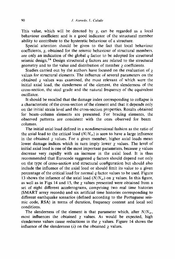
The initial axial load defined in a nondimensional fashion as the ratio of the axial load to the critical load (N/Nc,) is seen to have a large influence in the obtained Z values. For a given member, higher axial loads mean lower damage indices which in turn imply lower Z values. The level of initial axial load is one of the most important parameters, because Z values decrease very rapidly with an increase in the axial load. It is thus recommended that Eurocode suggested q factors should depend not only on the type of cross-section and structural configuration but should also include the influence of the axial load or should limit its value to a given percentage of the critical load for normal q factor values to be used. Figure 13 shows the infuence of the axial load (N/Ncr) on Z values. In this figure, as well as in Figs 14 and 15, the Z values presented were obtained from a set of eight different accelerograms, comprising two real time histories (SMART array records) and six artificial time histories corresponding to different earthquake scenarios (defined according to the Portuguese seis- mic code, RSA) in terms of duration, frequency content and local soil conditions.
The slenderness of the element is that parameter which, after N/N~,, most influences the obtained Z values. As would be expected, high slenderness values cause reductions in the Z values. Figure 14 shows the influence of the slenderness (2) on the obtained X values.

Hysteretic behaviour of steel members 91
Z
15.
10.
5 . . . . .
D = 9 2
0
0 .0
F i g . 13 , I n f l u e n c e o f t h e a x i a l l o a d o n t h e m e m b e r Z
. . . . +- . . . . ~ - - - - - - - - t . . . . - t . . . .
D = 3 6 I I I I
, -
~ D = 2 0 I
0.1
ta c o 0 24NS • CO0 35NS * R S A I I • RSA 1 II = RSA 1 III o R S A 2 I ,s R S A 2 II
RSA 2 I I I
IPE300
f = 1.50 H z
~, = 75
0.2 0.3 0.4 N / N e r
value.
z i i I
7 . 5 I I _ _
5 . 0
2.5 I D 6 2 8 I
0.0 . . . .
F i g . 14 . I n f l u e n c e o f t h e s l e n d e r n e s s o n t h e m e m b e r Z
g I
. . . . . 4-________~-______-~- . . . . -4 . . . . .
D = 32 I
g l
I i D = 2 6 I
. . . . I . . . . L . . . . i . . . . I
25 50 75 1OO
r~ COO 24NS • COO 35NS o R S A I I • RSA 1 II a RSA 1 1II o R S A 2 1
RSA 2 lI [] R S A 2 I l l
IPE300
f = 0.50 H z
N/Ncr = 0.20
value.
Z
7 . 5
5 . 0
2 . 5
0 .0
m
I I I
. . . . 4- . . . . ~ - - B - - - t . . . . -4 . . . .
_ I Fe360 I D = 2 8 I Fe510 I D = 2 1
[] COO 24NS ] • COO 35NS I o R S A I I I • RSA 1 I I I = RSA 1 I I I I o R S A 2 I I
RSA 2 I1 [] RSA 2 III
IPE300 N/Ncr = 0 .20 f = 0.67 H z
~,= 75
100 200 300 400 fy ( M P a )
F i g . 15 . I n f l u e n c e o f t h e s t e e l g r a d e o n t h e m e m b e r Z v a l u e .
The slenderness of the cross section does not greatly influence the obtained Z values. It should be noted that the slenderness of the cross section influences the damage index for collapse and so, indirectly influen- ces the value of Z as well.
The steel grade has a slight influence on the obtained Z values. Members with higher steel grades tend to be less ductile, causing the corresponding Z values to suffer a small reduction as is demonstrated in Fig. 15.

92 J. Azevedo. L. Calado
20'
15'
10'
5"
0 0
T T T T I I I I I l
l r T F - 7 ~- z : v .~v nz- [ I I 7 " j f '=0.67Hz
1 f~ 1.00 H z
I I ~ , ' J ~ , " 7 j f'-- 1.50Hz
i t / / j . r / t I
I F . . . , - ~ t i I I I I
i
20 40 60 80 100 120 D
Fig. 16. Inf luence of the na tura l f requency in the m e m b e r 7. value.
Finally, the trends observed for the influence of the natural frequency on Z, tend to agree with the Eurocode recommendations. Figure 16 shows the influence of the natural frequency on the relationship between the damage index (indirectly depending on N I N e , ) and the corresponding Z values. As can be seen from Fig. 16, for a given member and therefore for a given damage index at collapse (D), X values diminish with the increase of the initial natural frequency values (f).
This observation may be due to the variation of the equivalent natural frequency throughout the loading process. For instance, if a member with a high initial natural frequency is subjected to a time history with its energy concentrated in the low frequency range, it will require a high peak load value to cause the member to reach yield. However, as soon as the nonlinear regime is reached, its frequency diminishes, resonance with the loading occurs and it requires only a small increase in the peak value to cause collapse.
7 F I N A L R E M A R K S
The seismic analysis of steel structures can be performed based on models developed to simulate the hysteretic behaviour of their members. Two alternative methods are possible in this regard. The first of these is a direct nonlinear approach, where the safety control is performed by obtaining the results of the nonlinear structural response for several different time histories and checking those results against the admissible limit stages corresponding to the same control variables. This alternative has much to gain from a correct simulation of the several phenomena involved in the nonlinear hysteretic behaviour of steel members and on the correct evaluation of collapse.

Hysteretic behaviour of steel members 93
The other alternative, the more widespread in practical design procedures is based on adopted design q factors for structures. The evaluation of these q factors is thus an important aspect of the design procedure. This can be achieved in a manner similar to that adopted for the evaluation of Z values and greatly benefits from the conclusions withdrawn from these studies.
R E F E R E N C E S
1. Tang, D. & Clough, R., Shaking table earthquake response of steel frame. ASCE, 105 (ST1) (1979) 221-43.
2. Elnashai, A., E1-Ghazouli, A. & Dowling, P., Verification of pseudo-dynamic testing of steel members, J. Constructional Steel Res., 16 (1990) 153-61.
3. Maison, B. & Popov, E., Cyclic response prediction for braced steel frames. ASCE, 106 (ST7)(1980) 1401-16.
4. Popov, E. & Black, R., Steel struts under severe cyclic loadings. ASCE, 107 (ST9) (1980) 1857-81.
5. Ballio, G. & Calado, L., Steel bent sections under cyclic loads - Experimental and numerical approaches. Costruzioni Metalliche, XXXVIII (1) (1986) 1-23.
6. Ballio, G. & Zandonini, R., An experimental equipment to test steel structural members and subassemblages subjected to cyclic loads. Ingegneria Sismica, II (2) (1985) 25 40.
7. Ballio, G. & Perotti, F., Cyclic behaviour of axially loaded members; numeri- cal simulation and experimental verification. J. Constructional Steel Res., 7 (1987) 3-41.
8. Calado, L., Caracterizaq~o do comportamento de estruturas met~licas sob acq6es sismicas, PhD dissertation, Technical University of Lisbon, Lisbon, Portugal 1989.
9. Hjelmstad, K. & Popov, E., Seismic Behavior of Active Beam links in Eccentrically Braced Frames (UCB/EERC-83/15). Earthquake Engineering Research Center, University of California, CA, USA, 1983.
10. ECCS, Study on Design of Steel Building in Earthquake Zones, ECCS European Convention for Constructional Steelwork Technical Committee 1
Structural Safety and Loadings, Technical Working Group 1.3-Seismic Design, N ° 47/86, 1986.
1 I. Hancock, G., Local, distortional, and lateral buckling of ! beams. ASCE, 104 (STI 1) (1978) 1787-98.
12. Higginbotham, A. & Hanson, R., Axial hysteretic behaviour of steel members. ASCE, 102 (ST7) (1976) 1365-81.
13. Ikeha, K. & Mahin, S., A Refined Physical Theory Model for Predicting the Seismic Behaviour of Braced Steel Frames, (UCB/EERC-84/12). Earthquake Engineering Research Center, University of California, CA, USA, 1984.
14. Toyama, K., Seismic Behaviour of Steel Bent Bracing System (KICT Report N ° 41). Kajima Institute for Construction Technology, Japan, 1983.
15. Castiglioni, C., Modellazioni numerica di sezioni inflesse in acciaio soggette a carichi ciclici: influenza del legame costitutivo. Costruzioni Metalliche, XLI (1) (1989) 1 23.

94 J. Azevedo, L. Calado
16. Sih, G. & Madenci, E., Crack growth resistance characterized by the strain energy density function. Eng. Fracture Mechanics, 18 (2) (1983) 1159-71.
17. Miner, M., Cumulative damage in fatigue. J. Appl. Mechanics, ASCE, 67 (1945) A159-A164.
18. Park, Y., Ang, H.-S. & Wen, M., Damage-limiting aseismic design of buildings. Earthquake Spectra, 3 (1) (1987) 1-26.
19. Krawinkler, H., Zohrei, M., Irvani, B., Cofie, N. & Tamjed, H., Recommenda- tions for Experimental Studies on the Seismic Behavior of Steel Components and Materials. (Report N. 61). The John Blume Earthquake Engineering Center, Stanford University, USA, September 1983.
20. Calado, L. & Azevedo, J., A model for predicting the failure of structural steel elements. J. Constructional Steel Res., 14 (1989) 41-64.
21. Duarte, R., Costa, A. G. & Costa, A. C., Definition and quantification of behaviour coefficients based on structural reliability concepts. In Proc. 9th European Conference on Earthquake Engineering, Moscow, 7-C, 1990 pp. 3-12.
22. Guerra, C., Mazzolani, F. & Piluso, V., Evaluation of the q-factor in steel framed structures: state-of-art, lngegneria Sismica, 2 (1990) 42-63.
23. Ballio, G., ECCS approach for the design of steel structures to resist earthquakes. In Proc. IABSE-ECCS Syrup. Steel in Buildings, Luxembourg, 1985, pp. 373-80.
24. Plumier, A. & Boushaba, B., Relation entre la ductilit6 locale et le facteur de comportement sismique de structures en acier. Construction M~tallique, 2 (1988) 59-70.