Embed Size (px)
Citation preview

HYPRESCEC/ICMC 2015
Cool-down acceleration of G-M cryocoolers with thermal oscillations passively damped by helium
Robert WebberJean Delmas HYPRES, Inc.

HYPRES
Outline
Interest in thermal stability and rapid cool-down
SHI’s helium thermal damper
Cool-down with damper and calculations
Modified damper gas management and results
Additional thermal anchoring
CEC/ICMC 2015

HYPRESCEC/ICMC 2015
Superconducting electronic systems
Hypres and others have developed turn-key S.E. electronic systems:
Josephson Junction Primary Voltage Standards
Digital RF receivers
HYPRESCEC/ICMC 2015
Niobium JJ Ideal Cryo-requirements
0
0.2
0.4
0.6
0.8
1
1.2
0 2 4 6 8 10Temperature (K)
No
rma
lize
d I
c a
nd
Ic
Stable temperature
Critical currents of Junctions and bias points are temperature sensitive
Fast cool-down
Quick temperature excursion through superconducting / normal transition
Extraneous magnetic flux can lower the critical current of random junctions in a circuit, affecting performance – purge by heating to Tc

HYPRESCEC/ICMC 2015
SHI RDK-101DP
Room temperature gas buffer
Helium pot attached to 2nd
stage
Capillary tubeThermal link to 1st
stage
RDK-101-DP coldhead

HYPRESCEC/ICMC 2015
Damper/No damper Cool-downs
2
4
6
8
10
12
14
16
0 10 20 30 40
T2 (K)Pbuffer (BarA)
Time (mins)
Measured He pottemperature
Calculated He pottemperature
Pbuffer (BarA)
Measured 2nd stage temp,no damper
“Deflux” excursion cool-down much longer with damper
Buffer pressure follows dropping He pot temperature
Calculated cool-down agrees reasonably well with measurement

HYPRESCEC/ICMC 2015
Dominance of heat from capillary flow
2 3 4 5 6 7 8 9 10 11 120
10
20
30
40
50
60
Capillary flowHe in pot
Helium pot temperature (K)
Heat removed from Helium per unit change in
pot temperature (K)

HYPRESCEC/ICMC 2015
Calculated cool-down
𝒎𝒑=𝑴 −𝑴𝑯𝒆𝑽 𝒃
𝑹𝑻 𝒂𝒎𝒃{𝑷𝒑+∆𝑷 𝒊 }
�̇�𝒓𝒆𝒇=𝒎𝒑𝑪 �̇� 𝒑+∆𝒉�̇� Energy balance
Mass in He pot known function of pressure, so defining temperature

HYPRESCEC/ICMC 2015
Low charge pressure cool-downs
2
3
4
5
6
7
8
9
10
11
12
0 10 20 30 40 50
Helium pot temperature
(K)
Time (mins)
No valves, 2.0 MPa charge
No valves, 1.5 MPa charge
No valves, 1.1 MPa charge
0
10
20
30
40
50
60
70
80
90
100
2 4 6 8 10 12
Heat removed from helium per
unit change in pot temperature (J/K)
Helium pot temperature (K)
Capillary flow, 1.5 MPa charge
Capillary flow, 1.1 MPa charge
Capillary flow, 2.0 MPa charge
He in pot, 2.0 MPa charge
Lower charge pressure results in longer cool-down time Total mass flow through capillary is increased and peaks at lower temperature Rapidly changing density near critical point

HYPRESCEC/ICMC 2015
Damping effectiveness vs charge pressure
45
50
55
60
65
70
75
80
85
90
2 4 6 8 10 12
Effective heat capacity of
helium in pot @ 1 Hz
(J/m2/K)
Helium pot temperature (K)
2.0 MPa
1.8 MPa
1.6 MPa
1.4 MPa
1.2 MPa
1.0 MPa
Thermal skin depth ~ 0.1mm Damping effectiveness/unit area

HYPRESCEC/ICMC 2015
Modifications to He damper
Buffer tank
Vacuum enclosure
Thermal linkage
Helium gas lines
In-line relief valve
G-M coldhead
Helium pot
1st stage
2nd stage
Intermediate linkage
Modifications work passively
Spring-loaded non-return valves set to ~1/3 charge pressure (0.7 bar) Additional thermal linkage at lower temperature

HYPRESCEC/ICMC 2015
Cool-down with 0.7 MPa c.p. NRVs
3
4
5
6
7
8
9
10
11
0 10 20 30 40
Helium pot temperature
(K)
Time (mins)
No valves, calculated
7.0 bar cracking pressureNRVs, calculated7.0 bar cracking pressureNRVs, experiment
0
20
40
60
80
100
120
140
2 4 6 8 10 12
Heat removed
from helium per unit
change in pot
temperature (J/K)
Helium pot temperature (K)
0.7 MPa delta P inlet andoutlet capillary flow
0.7 MPa delta P inlet &outlet, pot He
No valves capillary flow
Measured cool-down is dramatically faster than without valves…. WHY??... ..Vapor-lock?......Thin film of liquid?
Calculated time to 4 K is no different, in spite of 55% reduction in
total capillary flow ---- heat load shifted to lower temperatures
HYPRESCEC/ICMC 2015
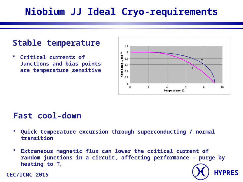
Addition of 7K thermal intercept to capillary
3
4
5
6
7
8
9
10
11
0 5 10 15 20 25 30
Helium pot temperature
(K)
Time (mins)
7.0 bar NRVs, 45K intercept, experiment
No valves, 45K intercept, experiment
7K intercept, 7.0 bar NRVs, calculated
7K intercept, 7.0 bar NRVs, experiment
No helium damper
0
5
10
15
20
25
30
35
40
2 4 6 8 10
Heat removed
from He per unit change
in pot temperature
(J/K)
He pot temperature (K)
He in pot
He from capillarytube
Even faster, approaching no-damper time
Still faster than calculated

HYPRESCEC/ICMC 2015
Conclusion
Cool-down from 10K is retarded by warm He injected into He pot
Reduction of charge pressure increases cool-down time
In-line relief valves passively restrict buffer-pot mass flow, with dramatic reduction in cool-down time
No reduction in damping
Additional inter-stage thermal intercept reduces time to nearly twice un-damped system

HYPRES
Sumitomo SRDK-101D-A11
Parameters Value
Heat Load (Manufacturer Spec)
0.1 W at 4.2 K and 5 W at 60K
Heat Load (Measured) 0.2 W at 4.2 K and 6 W at 53K
Input Power 1.3 kW, 10010 V (60 Hz)
Compressor Size 0.45 0.385 0.40 m3
Cold Head Dimension 0.13 0.226 0.442 m3
Compressor Weight 42 kg
Cold Head Weight 7.2 kg

HYPRES
Temperature Oscillations of Sumitomo Cooler
3.3
3.35
3.4
3.45
3.5
3.55
3.6
3.65
0 0.5 1 1.5 2
Time (s)
Tem
per
atu
re (
K)
250 mK