Embed Size (px)
Citation preview

433
Vibration-Free Joule-ThomsonCryocoolers for DistributedMicrocooling
W. Chen, M. Zagarola
Creare Inc.
Hanover, NH, USA
ABSTRACT
This paper reports on an innovative concept for a space-borne Joule-Thomson (J-T) cryocooler
that utilizes a continuous-flow compressor to provide cooling to multiple miniature cold heads. The
heat transport to each cooling site is accomplished at ambient temperature, allowing large separation
distances between cryocooler components and cooling sites with minimal performance impact. The
compressor uses non-contacting, gas-lubricated bearings and is a derivative of TRL 9 technology that
has demonstrated long life and high reliability. The concept addresses the limitations on life and
reliability normally associated with J-T cryocoolers. The key technical challenge is the development
of a Low-Specific-Speed (LSS) compressor to match the operating conditions of the J-T cycle. Cycle
analysis was carried out to identify the optimum operating conditions as well as the optimum compo-
sition of the cycle gas. An LSS compressor and a compact cold head were designed, and their perfor-
mance, mass, and size are estimated. The cryocooler is designed to provide 10 mW of cooling at
150 K to each of the multiple cold heads. The performance of an LSS impeller is measured and the
results are used to correlate a compressor design model. These studies demonstrate that a space-borne
J-T cryocooler can be produced to provide efficient cooling at extremely low capacities. The cryo-
cooler is lightweight, compact, extremely reliable, and emits negligible vibration. The scope of this
paper is the design of the cryocooler, the optimization of the cycle gas composition, and the prelimi-
nary test results for an LSS compressor impeller.
INTRODUCTION
Future space applications will require low capacity cryocoolers for distributed cooling of small arrays of infrared detectors, high-temperature superconducting electronics, or payload thermal management. Passive cryogenic radiators are often impractical to integrate with the objects to be cooled and are costly to ground test. Current low-capacity cryocoolers have low thermal efficiency because of relatively large parasitic losses. Joule-Thomson cryocoolers are ideal for applications that require distributed, low-capacity cooling because: (1) the cold heads in the cooler are very compact and thus minimize the parasitic heat leak; (2) multiple remotely located cold heads can share one compressor assembly; and (3) the fluid transport to each cooling site is accomplished at ambient temperature, allowing large separation distances between the compressor assembly and cold heads with minimal performance impact.
Current J-T cryocoolers utilizing linear compressors have limitations for space applications due to
high exported vibrations from the compressor.
To address these limitations, Creare began the development of a vibration-free, long-life cen-
trifugal compressor for a J-T cryocooler. The centrifugal compressor utilizes self-acting
gas bearings for vibration-free and long-life operation and an LSS impeller with unique clearance
shaft seals to achieve a relatively high compression ratio and efficiency at low flow rates. A mixed-
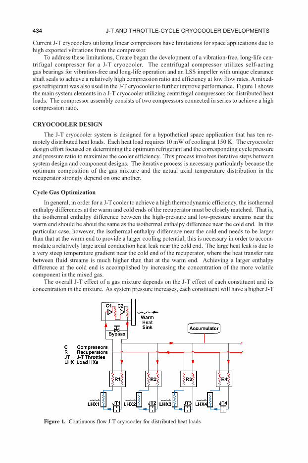
gas refrigerant was also used in the J-T cryocooler to further improve performance. Figure 1 shows
the main system elements in a J-T cryocooler utilizing centrifugal compressors for distributed heat
loads. The compressor assembly consists of two compressors connected in series to achieve a high
compression ratio.
CRYOCOOLER DESIGN
The J-T cryocooler system is designed for a hypothetical space application that has ten re-
motely distributed heat loads. Each heat load requires 10 mW of cooling at 150 K. The cryocooler
design effort focused on determining the optimum refrigerant and the corresponding cycle pressure
and pressure ratio to maximize the cooler efficiency. This process involves iterative steps between
system design and component designs. The iterative process is necessary particularly because the
optimum composition of the gas mixture and the actual axial temperature distribution in the
recuperator strongly depend on one another.
Cycle Gas Optimization
In general, in order for a J-T cooler to achieve a high thermodynamic efficiency, the isothermal
enthalpy differences at the warm and cold ends of the recuperator must be closely matched. That is,
the isothermal enthalpy difference between the high-pressure and low-pressure streams near the
warm end should be about the same as the isothermal enthalpy difference near the cold end. In this
particular case, however, the isothermal enthalpy difference near the cold end needs to be larger
than that at the warm end to provide a larger cooling potential; this is necessary in order to accom-
modate a relatively large axial conduction heat leak near the cold end. The large heat leak is due to
a very steep temperature gradient near the cold end of the recuperator, where the heat transfer rate
between fluid streams is much higher than that at the warm end. Achieving a larger enthalpy
difference at the cold end is accomplished by increasing the concentration of the more volatile
component in the mixed gas.
The overall J-T effect of a gas mixture depends on the J-T effect of each constituent and its
concentration in the mixture. As system pressure increases, each constituent will have a higher J-T
Figure 1. Continuous-flow J-T cryocooler for distributed heat loads.
434 J-t anD tHrottle-cycle cryocooler DevelopmentS
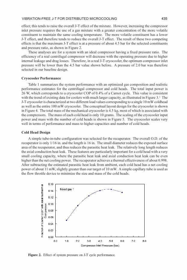
effect; this tends to raise the overall J-T effect of the mixture. However, increasing the compressor
inlet pressure requires the use of a gas mixture with a greater concentration of the more volatile
constituent to maintain the same cooling temperature. The more volatile constituent has a lower
J-T effect, and therefore tends to reduce the overall J-T effect. The result of these two competing
effects is that the maximum J-T effect is at a pressure of about 4.5 bar for the selected constituents
and pressure ratio, as shown in Figure 2.
These analyses are for a system with an ideal compressor having a fixed pressure ratio. The
efficiency of a real centrifugal compressor will decrease with the operating pressure due to higher
internal leakage and drag losses. Therefore, in a real J-T cryocooler, the optimum compressor inlet
pressure will be lower than the 4.5 bar value shown before. A pressure of 2.0 bar was therefore
selected in our baseline design.
Cryocooler Performance
Table 1 summarizes the system performance with an optimized gas composition and realistic
performance estimates for the centrifugal compressor and cold heads. The total input power is
26 W, which corresponds to a cryocooler COP of 0.4% of a Carnot cycle. This value is consistent
with the trend of existing data for coolers with much larger capacity, as illustrated in Figure 3.1 The
J-T cryocooler is characterized at two different load values corresponding to a single 10 mW coldhead
as well as the entire 100 mW cryocooler. The conceptual layout design for the cryocooler is shown
in Figure 4. The total mass of the mechanical cryocooler is 4.5 kg, most of which is associated with
the compressors. The mass of each cold head is only 10 grams. The scaling of the cryocooler input
power and mass with the number of cold heads is shown in Figure 5. The cryocooler scales very
well in terms of performance and mass to higher capacities and number of cold heads.
Cold Head Design
A simple tube-in-tube configuration was selected for the recuperator. The overall O.D. of the
recuperator is only 1/16 in. and the length is 16 in. The small diameter reduces the exposed surface
area of the recuperator, and thus reduces the parasitic heat leak. The relatively long length reduces
the axial conduction heat leak. These features are particularly important for a cold head with a very
small cooling capacity, where the parasitic heat leak and axial conduction heat leak can be even
higher than the net cooling power. The recuperator achieves a thermal effectiveness of about 0.998.
After subtracting the estimated parasitic heat leak from ambient, each cold head has a net cooling
power of about 11 mW, slightly greater than our target of 10 mW. A simple capillary tube is used as
the flow throttle device to minimize the size and mass of the cold heads.
Figure 2. Effect of system pressure on J-T cycle performance.
435vibration-free J-t for DiStributeD microcooling

Figure 3. Cryocooler performance comparison.
Figure 4. Conceptual design of J-T cryocooler.
Table 1. Predicted performance of J-T cryocooler.
436 J-t anD tHrottle-cycle cryocooler DevelopmentS
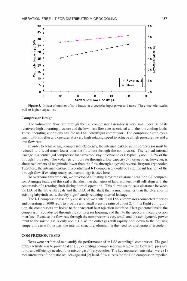
Figure 5. Impact of number of cold heads on cryocooler input power and mass. The cryocooler scales
well to higher capacities.
Compressor Design
The volumetric flow rate through the J-T compressor assembly is very small because of its
relatively high operating pressure and the low mass flow rate associated with the low cooling loads.
These operating conditions call for an LSS centrifugal compressor. The compressor employs a
small LSS impeller and operates at a very high rotating speed to achieve a high pressure rise and a
low flow rate.
In order to achieve high compressor efficiency, the internal leakage in the compressor must be
reduced to a level much lower than the flow rate through the compressor. The typical internal
leakage in a centrifugal compressor for a reverse-Brayton cryocooler is typically about 1-2% of the
through flow rate. The volumetric flow rate through a low-capacity J-T cryocooler, however, is
about two orders of magnitude lower than the flow through a typical reverse-Brayton cryocooler.
Therefore, the internal leakage in a centrifugal J-T compressor could be a significant fraction of the
through flow if existing rotary seal technology is used here.
To overcome this problem, we developed a floating labyrinth clearance seal for a J-T compres-
sor. A unique feature of this seal is that the inner diameters of labyrinth teeth will self-align with the
center axis of a rotating shaft during normal operation. This allows us to use a clearance between
the I.D. of the labyrinth seals and the O.D. of the shaft that is much smaller than the clearance in
existing labyrinth seals, thereby significantly reducing internal leakage.
The J-T compressor assembly consists of two centrifugal LSS compressors connected in series
and operating at 8000 rev/s to provide an overall pressure ratio of about 2.4. In a flight configura-
tion, the compressors are bolted to the spacecraft heat rejection interface. Heat generated inside the
compressor is conducted through the compressor housing, and then to the spacecraft heat rejection
interface. Because the flow rate through the compressor is very small and the aerodynamic power
input to the mixed gas is only about 1.2 W, the outlet gas will rapidly cool down to the housing
temperature as it flows past the internal structure, eliminating the need for a separate aftercooler.
COMPRESSOR TESTS
Tests were performed to quantify the performance of an LSS centrifugal compressor. The goal
of this activity was to prove that an LSS centrifugal compressor can achieve the flow rate, pressure
ratio, and efficiency needed for a mixed-gas J-T cryocooler. The key measurements taken were (1)
measurements of the static seal leakage and (2) head-flow curves for the LSS compressor impeller.
437vibration-free J-t for DiStributeD microcooling

Figure 6. Schematic of compressor test setup
The schematic of the test setup is shown in Figure 6. The setup consists of two main compo-
nents: (1) a commercially available spindle, with a rotational speed up to 250,000 rpm (4200 rev/s)
to drive the rotor; and (2) a test chamber that houses the rotor and floating seals. To reduce the
complexity of sealing the test chamber at the shaft pass-through, we tested with a ambient pressure
gas with a high molecular weight (SF6), instead of the actual high-pressure gas. The pressure in the test
chamber was maintained slightly above the ambient pressure to prevent air from flowing into the test rig.
Leak Tests
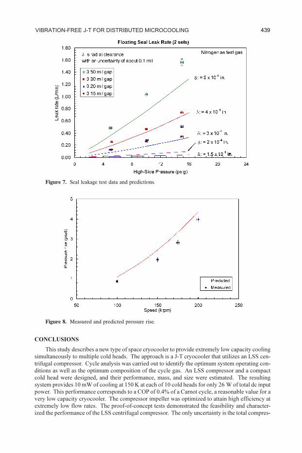
The leakage through the floating seals was directly measured in the test setup by supplying a
high-pressure gas at the outlet and using a shaft without an impeller. The backward flow rate from
the outlet to the chamber is equivalent to the leakage rate across the seals. The measured and
predicted leakages are shown in Figure 7. The error bars shown represent the measurement uncer-
tainty. There is an uncertainty in the predicted leakage because of uncertainty in the exact clearance
and concentricity between the shaft and seal. This clearance uncertainty is due to the uncertainties
in the physical measurement of the shaft and seal diameters that are of the same order of magnitude
as the clearances. The measured leakage was slightly higher than the predicted leakage for all
clearances, but consistent with predicted values when the uncertainties of the predictions (0.0001 in.
clearance uncertainty) are also considered.
Using floating seals with a clearance of about 0.0002 in., no mechanical interference was found
for a precision-ground shaft spinning at speeds of about 150,000 rpm. From this result, along with
the leakage tests, it was concluded that a radial clearance value of 0.0002 in. to 0.0003 in. was
physically feasible in that the shaft and seals could be manufactured to the required tolerance and
assembled. A seal clearance of approximately 0.0002 in. was then used in the compressor design.
Compressor Pressure Rise
The performance of the impeller was measured for one seal-clearance value of 0.0005 in. The
impeller test results are shown in Figure 8. Here, pressure rise is shown as a function of rotation
speed, with error bars representing the measurement uncertainty. The measured pressure rise was
slightly lower than the predicted pressure rise for a given rotational speed, but the trend with speed
is consistent with the predictions. The lower pressure rise may be attributed to larger-than-pre-
dicted internal leakage and over-restricted flow channels in the impeller. Assuming the measured
pressure rise was not improved upon by future design improvement, the impeller would need to
operate at a 9% higher tip speed, which would result in an increase of electrical input power from
26 W to 31 W.
438 J-t anD tHrottle-cycle cryocooler DevelopmentS
CONCLUSIONS
This study describes a new type of space cryocooler to provide extremely low capacity cooling
simultaneously to multiple cold heads. The approach is a J-T cryocooler that utilizes an LSS cen-
trifugal compressor. Cycle analysis was carried out to identify the optimum system operating con-
ditions as well as the optimum composition of the cycle gas. An LSS compressor and a compact
cold head were designed, and their performance, mass, and size were estimated. The resulting
system provides 10 mW of cooling at 150 K at each of 10 cold heads for only 26 W of total dc input
power. This performance corresponds to a COP of 0.4% of a Carnot cycle, a reasonable value for a
very low capacity cryocooler. The compressor impeller was optimized to attain high efficiency at
extremely low flow rates. The proof-of-concept tests demonstrated the feasibility and character-
ized the performance of the LSS centrifugal compressor. The only uncertainty is the total compres-
Figure 7. Seal leakage test data and predictions.
Figure 8. Measured and predicted pressure rise.
439vibration-free J-t for DiStributeD microcooling

sor input power. However, the uncertainty has been bounded by the results of these tests. The total
mechanical cryocooler mass is estimated to be 4.5 kg. Each cold head weighs only 10 grams. The
system scales well to higher capacities, requiring only 0.25 W of additional input power for each
10 mW cold head.
The technology discussed in this study can be applied to low-capacity cooling at temperatures
ranging from 200 K to 70 K. In addition, it can be used as the lowest stage cooler in a multistage,
low-temperature cryocooler with cooling temperatures below 10 K to provide efficient, remote
cooling.
ACKNOWLEDGMENT
The support and guidance provided by the Missile Defense Agency and the Air Force Research
Laboratory are gratefully acknowledged.
REFERENCES
1. Burger, J., “Cryogenic Microcooling, a Micromachined Cold Stage Operating with a Sorption Com-
pressor in a Vapor Compression Cycle,” Ph.D. Thesis, Twente University, 2001.
440 J-t anD tHrottle-cycle cryocooler DevelopmentS