Embed Size (px)
Citation preview
1
®
HYFIRE® VI SERIES OF ELECTRONICIGNITION CONTROLS
HYFIRE® VI Ignition System Part No. 685, AdvancedHYFIRE® VI Ignition System Part No. 6851, Basic
For applications triggered by points, Mallory Electronic Ignition Distributor (all models), original equipment electronicignition amplifiers and magnetic trigger pulses (magnetic pickup distributor or crank trigger ignition). Optional adaptersare available for easy connection to early model Delco/GM HEI Systems, late model GM HEI/EST Systems, Ford TFISystems, and OEM magnetic pickup (non-computer; Ford DuraSpark, GM HEI and Mopar/Chrysler Electronic Systems).
This product is legal to sell, distribute or install on vehicles in California. C.A.R.B. Executive Order D-70-26.
NOTE: Mallory HYFIRE® VI Electronic Ignition Controls are not compatible with distributorless systems or positiveground applications. The RPM Limiter in the HYFIRE® VI (Part No. 685) will not work properly with odd-fire or semi-evenfire V6 applications.
Parts included in this kit:1 HYFIRE® VI Electronic Ignition Control - Part No. 685 or 68511 Ignition Control Harness - Part No. 293482 Terminal Connectors - Part No. 4501 Bypass Connector4 Cable Ties2 Spade Terminals
8 Ring Terminals, 1/4"1 Ring Terminal, 3/8"5 Spade Receptacle Terminals4 10-32 Screws4 10-32 Nuts with Lockwashers
INSTALLATION INSTRUCTIONS
FORM 1478 (REV. C) 6/00
WARNING: DO NOT USE NON-SUPPRESSOR SPARK PLUGWIRES WITH THE HYFIRE® VI IGNITION CONTROL.
KEEP ALL IGNITION SYSTEM WIRES AS FAR FROM SPARK PLUG WIRES AS POSSIBLE.
General Information .............................................................................. 2Ignition Ballast Resistor/Loom Resistance Wire ........................... 2Standard Ignition Bypass (Bypass Connector) ............................. 2Ignition Coils ................................................................................... 2Fuel Injection ................................................................................... 2Spark Plug Wires ............................................................................. 2Spark Plug Gaps ............................................................................. 2Electric Welding .............................................................................. 2External RPM LimitersMallory PRO TACH® I, IV and VI ...................................................... 2
Mounting Procedure ............................................................................. 2Mounting to a Flat Surface Without Brackets ............................... 2Mounting to a Flat or Uneven Surface Using Brackets ................ 2Mounting to a Flat Surface with Shock Mounts ........................... 2
Wiring Procedure .................................................................................. 3Wiring Method using Adapters and Harnesses ............................. 3
GM HEI Systems/coil-in-cap with OEM module) .................. 3-4Late Model GM HEI/EST Systems (external coil) ................. 3-5
Ford TFI Systems ........................................................................ 3-4Ford DuraSpark Systems (non-computer type,
without module) .................................................................... 5-6
Early Model GM HEI Systems (non-computer type,without module) .................................................................... 6, 8
Mopar/Chrysler Corp. Electronic Systems(non-computer type, without module) .................................. 6, 9
Wiring Method Without Adapters ......................................................... 7Breaker Point Systems ............................................................... 7, 9Mallory Electronic Ignition, UNILITE® Distributors,
Magnetic Breakerless Distributors or ElectronicAdvance Distributors (3-wire/red, brown, green) ............... 7, 10
For OEM Electronic Systems with modules/amplifiers(Chrysler, Ford, and import) ............................................... 7, 10
Magnetic Pickup Trigger Pulses (magneticpickup distributors or crank trigger ignition) .......................... 7, 10
Top Panel Operation and Features ................................................... 11RPM Limiter Operation � HYFIRE® VI Ignition System
(PN 685 only) ................................................................................. 11
Optional Ignition Accessories ............................................................ 11Bypass Connector .............................................................................. 12Mounting Template ............................................................................ 12
CONTENTS
2
GENERAL INFORMATION
The HYFIRE® VI Ignition System Part Nos. 685 and 6851 are not for marine use.The RPM limiter in the HYFIRE® VI is not recommended as an engine speed governor. Theuse of the RPM limiters is not recommended for applications equipped with a catalyticconverter. Similarly, forcing engine RPM past the RPM limiter continuously for long sustainedintervals can cause fuel build up in the exhaust system that may adversely affect yourapplication. The RPM limiting systems will not work properly with odd-fire V6 applications.
Ignition Ballast Resistor / Loom Resistance WireThe performance of the HYFIRE® VI is not affected by the presence of the factory ignitionresistors or ignition ballast resistors in the wire from the ignition switch.
Standard Ignition Bypass (Bypass Connector)The Bypass Connector (supplied) fits into the Ignition Control Harness to convert back tostandard ignition. If you use the Bypass Connector, use ignition ballast resistors designed foryour vehicle�s distributor and coil (see diagrams for more information). This bypass methoddoes not work with magnetic pickup distributor or crank trigger ignition. Racing Applications: Itis not necessary to install ignition ballast resistors. However, do not use the Bypass Connectoruntil the ignition ballast resistors are installed in the wire from the ignition switch.
Ignition CoilsThe HYFIRE® VI Electronic Ignition Controls are designed to work with most originalequipment ignition coils. For optimum performance use the Mallory PROMASTER® Coil PartNo. 29440 (up to 7,500 RPM) or Part No. 29625 (up to 10,000 RPM).
Fuel InjectionSome fuel injection systems need a voltage spike signal from the ignition coil before they willoperate properly. This signal changes once HYFIRE® VI Electronic Ignition Controls areinstalled. The Mallory Fuel Injection and Tachometer Adapters Part Nos. 29074 and 29078supply the proper signal to the vehicle computer to operate the fuel injection system.Installation procedure and diagrams are supplied with these adapters.
Spark Plug WiresYOU MUST USE suppression type (carbon core, spiral core, suppression core) spark plugwire. We recommend spiral core ignition wire, such as Mallory PRO SIDEWINDER® IgnitionWire. Suppression type spark plug wires prevent false triggering and possible prematureignition or accessory failures. DO NOT USE solid core (copper core; stainless steel core)spark plug wire with any electronic ignition system or accessory.
Spark Plug GapsFor street applications, use your engine manufacturer's specifications. For racing applications,start with your engine manufacturer's specifications, then experiment with, and closely monitor,various gaps to achieve maximum performance.
Electric WeldingUnplug the Ignition Control Harness from the HYFIRE® VI Electronic Ignition Control andunplug any distributor harnesses (if possible) before any welding is done on the vehicle.
External RPM LimitersMallory Proportional RPM Limiter Part Nos. 641-4, 641-6, 641-8, 642, 643 and 644 WILL NOTfunction with the HYFIRE® VI Electronic Ignition Controls.
Mallory PRO TACH® I, IV and VIThe RPM needle and shift light will work with the HYFIRE® VI. However, the tach's proportionalcontroller that limits RPM WILL NOT function with the HYFIRE® VI. Turn the LIMIT RPM knobslightly past 11,000 to prevent the limiter from interfering with the tach�s other functions. SeeOptional Ignition Accessories for more information.
MOUNTING PROCEDURE
Step 1Disconnect the battery (�) cable to cut power to the system. Computerized vehicles:Disconnect the battery (�) cable and let the vehicle sit overnight before proceeding. This allowsthe computer to calibrate for the new ignition.
Step 2Select a convenient location to mount the HYFIRE® VI Electronic Ignition Control. Keep theunit away from hot engine components or extreme heat such as the exhaust system andmanifolds. Also, keep it away from moving devices, such as fans, belts and linkages. Thelocation must be dry. Moisture will damage components inside the unit.
Step 3Choose one mounting method listed below for mounting the HYFIRE® VI Electronic IgnitionControl (3a, 3b, or 3c).
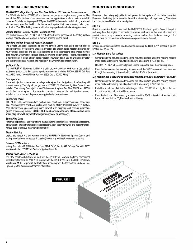
(3a) Mounting to a flat surface
� Center punch the mounting pattern on the mounting surface using the housing holes tomark locations for drilling mounting holes. Drill holes using a 7/32" drill bit.
� Hold the HYFIRE® VI Electronic Ignition Control in position over the mounting holes.
� From the backside of the mounting surface, insert the 10-32 screws with lock washersthrough the mounting holes and attach with the 10-32 nuts supplied.
(3c) Mounting to a flat surface with shock mounts (available separately, PN 29069)
� Center punch the mounting pattern on the mounting surface using the housing holes tomark locations for drilling mounting holes. Drill holes using a 7/32" drill bit.
� Install the shock mounts into the side flanges of the HYFIRE® VI and tighten nuts. Holdthe unit in position where it will be mounted.
� From the backside of the mounting surface, insert the 10-32 nuts with lock washers ontothe shock mount studs. Tighten each nut until snug.
®
FIGURE 1
3
BASIC WIRING PROCEDURE
Step 1
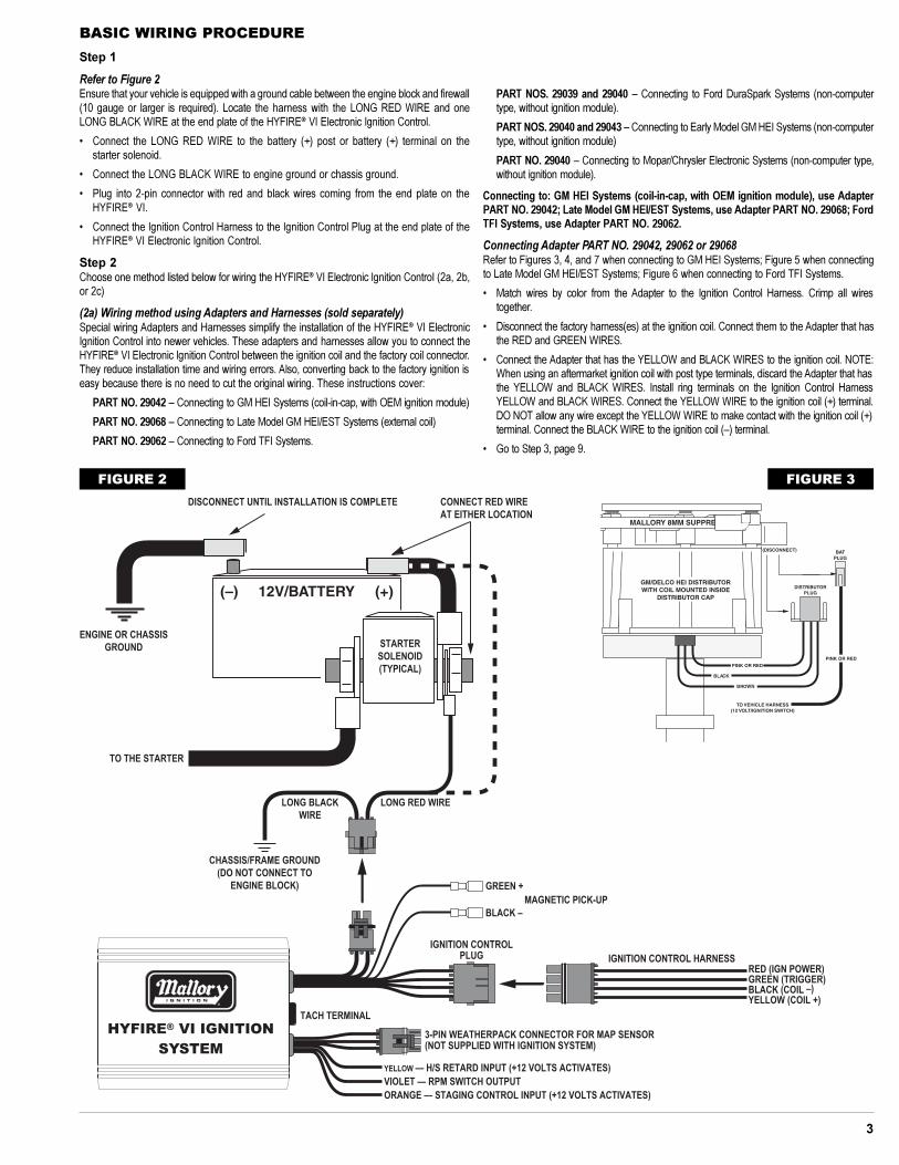
Refer to Figure 2Ensure that your vehicle is equipped with a ground cable between the engine block and firewall(10 gauge or larger is required). Locate the harness with the LONG RED WIRE and oneLONG BLACK WIRE at the end plate of the HYFIRE® VI Electronic Ignition Control.
� Connect the LONG RED WIRE to the battery (+) post or battery (+) terminal on thestarter solenoid.
� Connect the LONG BLACK WIRE to engine ground or chassis ground.
� Plug into 2-pin connector with red and black wires coming from the end plate on theHYFIRE® VI.
� Connect the Ignition Control Harness to the Ignition Control Plug at the end plate of theHYFIRE® VI Electronic Ignition Control.
Step 2Choose one method listed below for wiring the HYFIRE® VI Electronic Ignition Control (2a, 2b,or 2c)
(2a) Wiring method using Adapters and Harnesses (sold separately)Special wiring Adapters and Harnesses simplify the installation of the HYFIRE® VI ElectronicIgnition Control into newer vehicles. These adapters and harnesses allow you to connect theHYFIRE® VI Electronic Ignition Control between the ignition coil and the factory coil connector.They reduce installation time and wiring errors. Also, converting back to the factory ignition iseasy because there is no need to cut the original wiring. These instructions cover:
PART NO. 29042 � Connecting to GM HEI Systems (coil-in-cap, with OEM ignition module)
PART NO. 29068 � Connecting to Late Model GM HEI/EST Systems (external coil)
PART NO. 29062 � Connecting to Ford TFI Systems.
PART NOS. 29039 and 29040 � Connecting to Ford DuraSpark Systems (non-computertype, without ignition module).
PART NOS. 29040 and 29043 � Connecting to Early Model GM HEI Systems (non-computertype, without ignition module)
PART NO. 29040 � Connecting to Mopar/Chrysler Electronic Systems (non-computer type,without ignition module).
Connecting to: GM HEI Systems (coil-in-cap, with OEM ignition module), use AdapterPART NO. 29042; Late Model GM HEI/EST Systems, use Adapter PART NO. 29068; FordTFI Systems, use Adapter PART NO. 29062.
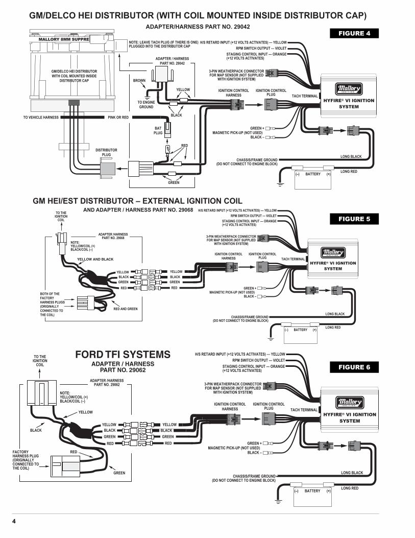
Connecting Adapter PART NO. 29042, 29062 or 29068Refer to Figures 3, 4, and 7 when connecting to GM HEI Systems; Figure 5 when connectingto Late Model GM HEI/EST Systems; Figure 6 when connecting to Ford TFI Systems.
� Match wires by color from the Adapter to the Ignition Control Harness. Crimp all wirestogether.
� Disconnect the factory harness(es) at the ignition coil. Connect them to the Adapter that hasthe RED and GREEN WIRES.
� Connect the Adapter that has the YELLOW and BLACK WIRES to the ignition coil. NOTE:When using an aftermarket ignition coil with post type terminals, discard the Adapter that hasthe YELLOW and BLACK WIRES. Install ring terminals on the Ignition Control HarnessYELLOW and BLACK WIRES. Connect the YELLOW WIRE to the ignition coil (+) terminal.DO NOT allow any wire except the YELLOW WIRE to make contact with the ignition coil (+)terminal. Connect the BLACK WIRE to the ignition coil (�) terminal.
� Go to Step 3, page 9.
®
FIGURE 2
BLA
BRO
FIGURE 3
4
AB
CD
®
FIGURE 5
AB
CD
MALLORY 8MM SUPPRE
®
FIGURE 4
AB
CD
®
FIGURE 6
5
®
FIGURE 8
®
FIGURE 7
6
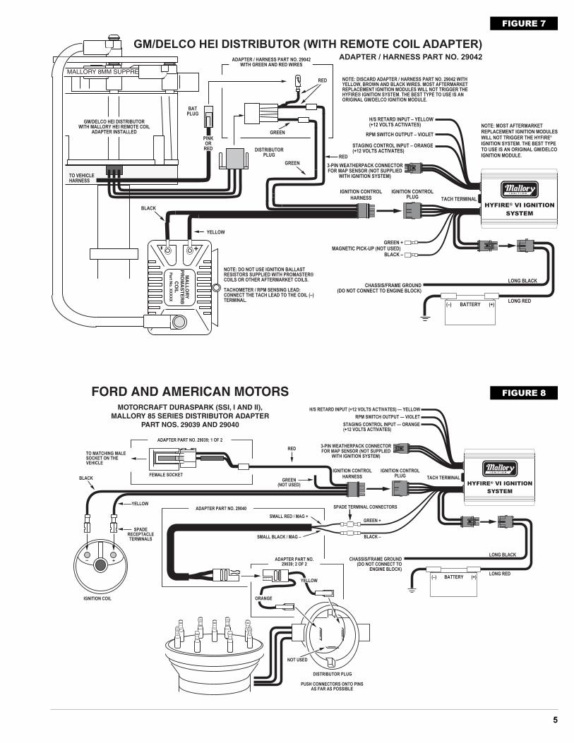
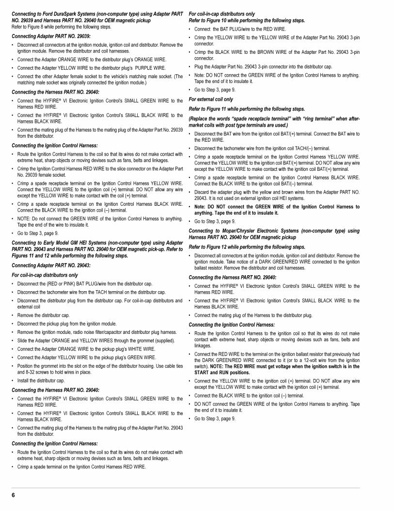
Connecting to Ford DuraSpark Systems (non-computer type) using Adapter PARTNO. 29039 and Harness PART NO. 29040 for OEM magnetic pickupRefer to Figure 8 while performing the following steps.
Connecting Adapter PART NO. 29039:
� Disconnect all connectors at the ignition module, ignition coil and distributor. Remove theignition module. Remove the distributor and coil harnesses.
� Connect the Adapter ORANGE WIRE to the distributor plug�s ORANGE WIRE.
� Connect the Adapter YELLOW WIRE to the distributor plug�s PURPLE WIRE.
� Connect the other Adapter female socket to the vehicle�s matching male socket. (Thematching male socket was originally connected the ignition module.)
Connecting the Harness PART NO. 29040:
� Connect the HYFIRE® VI Electronic Ignition Control�s SMALL GREEN WIRE to theHarness RED WIRE.
� Connect the HYFIRE® VI Electronic Ignition Control�s SMALL BLACK WIRE to theHarness BLACK WIRE.
� Connect the mating plug of the Harness to the mating plug of the Adapter Part No. 29039from the distributor.
Connecting the Ignition Control Harness:
� Route the Ignition Control Harness to the coil so that its wires do not make contact withextreme heat, sharp objects or moving devises such as fans, belts and linkages.
� Crimp the Ignition Control Harness RED WIRE to the slice connector on the Adapter PartNo. 29039 female socket.
� Crimp a spade receptacle terminal on the Ignition Control Harness YELLOW WIRE.Connect the YELLOW WIRE to the ignition coil (+) terminal. DO NOT allow any wireexcept the YELLOW WIRE to make contact with the coil (+) terminal.
� Crimp a spade receptacle terminal on the Ignition Control Harness BLACK WIRE.Connect the BLACK WIRE to the ignition coil (�) terminal.
� NOTE: Do not connect the GREEN WIRE of the Ignition Control Harness to anything.Tape the end of the wire to insulate it.
� Go to Step 3, page 9.
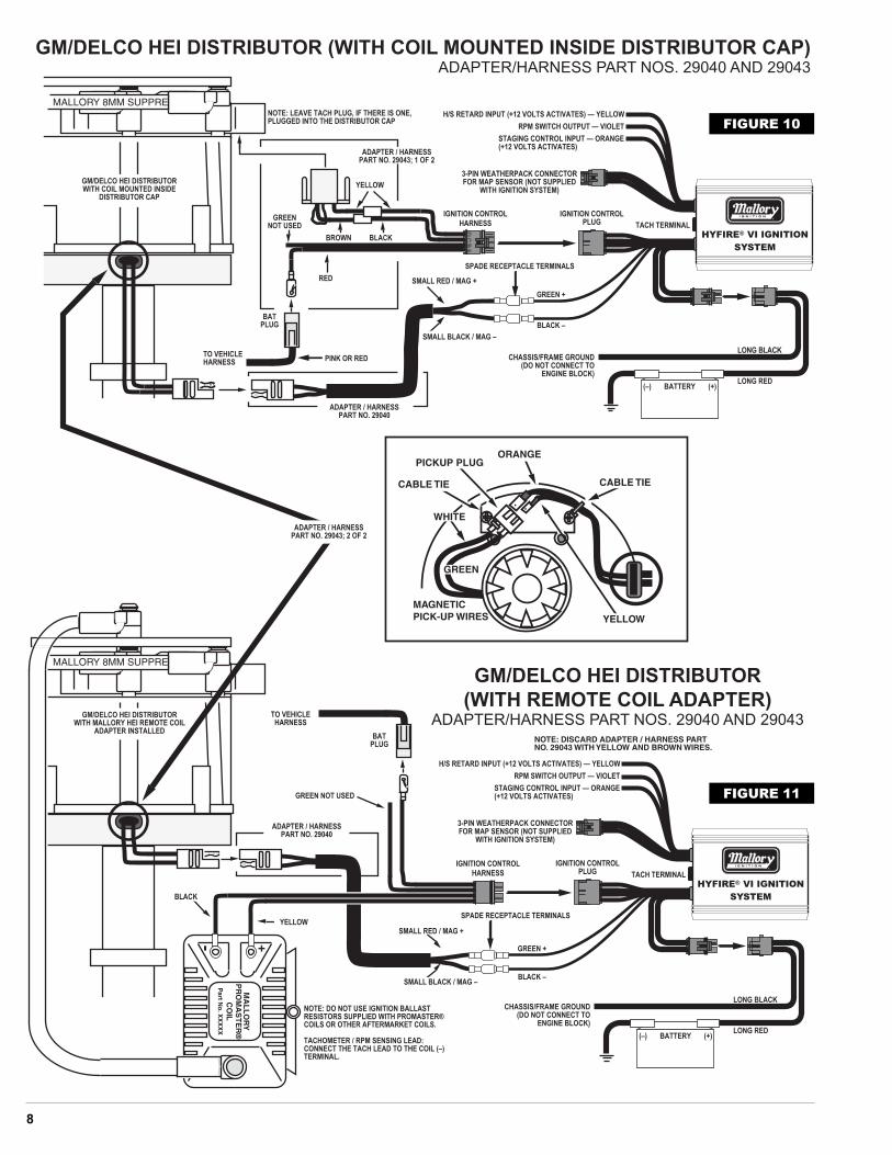
Connecting to Early Model GM HEI Systems (non-computer type) using AdapterPART NO. 29043 and Harness PART NO. 29040 for OEM magnetic pick-up. Refer toFigures 11 and 12 while performing the following steps.
Connecting Adapter PART NO. 29043:
For coil-in-cap distributors only
� Disconnect the (RED or PINK) BAT PLUG/wire from the distributor cap.
� Disconnect the tachometer wire from the TACH terminal on the distributor cap.
� Disconnect the distributor plug from the distributor cap. For coil-in-cap distributors andexternal coil
� Remove the distributor cap.
� Disconnect the pickup plug from the ignition module.
� Remove the ignition module, radio noise filter/capacitor and distributor plug harness.
� Slide the Adapter ORANGE and YELLOW WIRES through the grommet (supplied).
� Connect the Adapter ORANGE WIRE to the pickup plug�s WHITE WIRE.
� Connect the Adapter YELLOW WIRE to the pickup plug�s GREEN WIRE.
� Position the grommet into the slot on the edge of the distributor housing. Use cable tiesand 8-32 screws to hold wires in place.
� Install the distributor cap.
Connecting the Harness PART NO. 29040:
� Connect the HYFIRE® VI Electronic Ignition Control�s SMALL GREEN WIRE to theHarness RED WIRE.
� Connect the HYFIRE® VI Electronic Ignition Control�s SMALL BLACK WIRE to theHarness BLACK WIRE.
� Connect the mating plug of the Harness to the mating plug of the Adapter Part No. 29043from the distributor.
Connecting the Ignition Control Harness:
� Route the Ignition Control Harness to the coil so that its wires do not make contact withextreme heat, sharp objects or moving devises such as fans, belts and linkages.
� Crimp a spade terminal on the Ignition Control Harness RED WIRE.
For coil-in-cap distributors onlyRefer to Figure 10 while performing the following steps.
� Connect the BAT PLUG/wire to the RED WIRE.
� Crimp the YELLOW WIRE to the YELLOW WIRE of the Adapter Part No. 29043 3-pinconnector.
� Crimp the BLACK WIRE to the BROWN WIRE of the Adapter Part No. 29043 3-pinconnector.
� Plug the Adapter Part No. 29043 3-pin connector into the distributor cap.
� Note: DO NOT connect the GREEN WIRE of the Ignition Control Harness to anything.Tape the end of it to insulate it.
� Go to Step 3, page 9.
For external coil only
Refer to Figure 11 while performing the following steps.
(Replace the words �spade receptacle terminal� with �ring terminal� when after-market coils with post type terminals are used.)
� Disconnect the BAT wire from the ignition coil BAT/(+) terminal. Connect the BAT wire tothe RED WIRE.
� Disconnect the tachometer wire from the ignition coil TACH/(�) terminal.
� Crimp a spade receptacle terminal on the Ignition Control Harness YELLOW WIRE.Connect the YELLOW WIRE to the ignition coil BAT/(+) terminal. DO NOT allow any wireexcept the YELLOW WIRE to make contact with the ignition coil BAT/(+) terminal.
� Crimp a spade receptacle terminal on the Ignition Control Harness BLACK WIRE.Connect the BLACK WIRE to the ignition coil BAT/(�) terminal.
� Discard the adapter plug with the yellow and brown wires from the Adapter PART NO.29043. It is not used on external ignition coil HEI systems.
� Note: DO NOT connect the GREEN WIRE of the Ignition Control Harness toanything. Tape the end of it to insulate it.
� Go to Step 3, page 9.
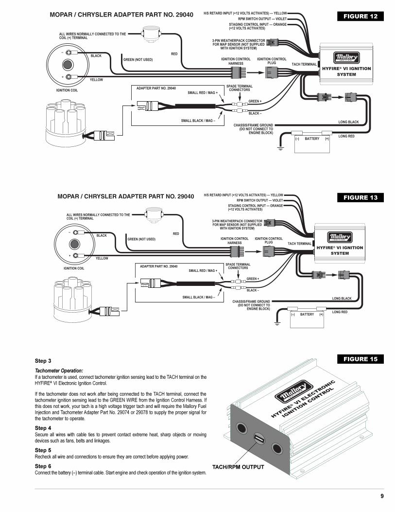
Connecting to Mopar/Chrysler Electronic Systems (non-computer type) usingHarness PART NO. 29040 for OEM magnetic pickup
Refer to Figure 12 while performing the following steps.
� Disconnect all connectors at the ignition module, ignition coil and distributor. Remove theignition module. Take notice of a DARK GREEN/RED WIRE connected to the ignitionballast resistor. Remove the distributor and coil harnesses.
Connecting the Harness PART NO. 29040:
� Connect the HYFIRE® VI Electronic Ignition Control�s SMALL GREEN WIRE to theHarness RED WIRE.
� Connect the HYFIRE® VI Electronic Ignition Control�s SMALL BLACK WIRE to theHarness BLACK WIRE.
� Connect the mating plug of the Harness to the distributor plug.
Connecting the Ignition Control Harness:
� Route the Ignition Control Harness to the ignition coil so that its wires do not makecontact with extreme heat, sharp objects or moving devices such as fans, belts andlinkages.
� Connect the RED WIRE to the terminal on the ignition ballast resistor that previously hadthe DARK GREEN/RED WIRE connected to it (or to a 12-volt wire from the ignitionswitch). NOTE: The RED WIRE must get voltage when the ignition switch is in theSTART and RUN positions.
� Connect the YELLOW WIRE to the ignition coil (+) terminal. DO NOT allow any wireexcept the YELLOW WIRE to make contact with the ignition coil (+) terminal.
� Connect the BLACK WIRE to the ignition coil (�) terminal.
� DO NOT connect the GREEN WIRE of the Ignition Control Harness to anything. Tapethe end of it to insulate it.
� Go to Step 3, page 9.
7
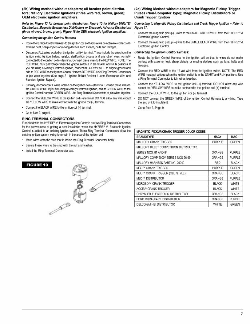
MAGNETIC PICKUP/CRANK TRIGGER COLOR CODES
BRAND/TYPE MAG+ MAG�
MALLORY CRANK TRIGGER PURPLE GREEN
MALLORY BILLET COMPETITION DISTRIBUTOR,
SERIES NOS. 81 AND 84 ORANGE PURPLE
MALLORY COMP 9000® SERIES NOS 96-99 ORANGE PURPLE
MALLORY HARNESS PART NO. 29040 RED BLACK
MSD� CRANK TRIGGER PURPLE GREEN
MSD� CRANK TRIGGER (OLD STYLE) ORANGE BLACK
MSD� DISTRIBUTOR ORANGE PURPLE
MOROSO� CRANK TRIGGER BLACK WHITE
ACCEL® CRANK TRIGGER BLACK WHITE
CHRYSLER ELECTRONIC DISTRIBUTOR ORANGE BLACK
FORD DURASPARK DISTRIBUTOR ORANGE PURPLE
DELCO/GM HEI DISTRIBUTOR WHITE GREEN
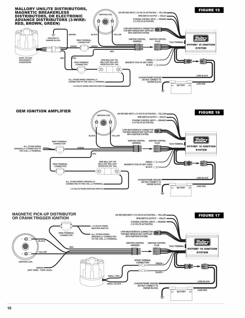
(2b) Wiring method without adapters; all breaker point distribu-tors; Mallory Electronic Ignitions (three wire/red, brown, green);OEM electronic ignition amplifiers.
Refer to: Figure 13 for breaker point distributors; Figure 15 for Mallory UNILITE®
Distributors, Magnetic Breakerless Distributors or Electronic Advance Distributors(three wire/red, brown, green); Figure 16 for OEM electronic ignition amplifiers
Connecting the Ignition Control Harness
� Route the Ignition Control Harness to the ignition coil so that its wires do not make contact withextreme heat, sharp objects or moving devises such as fans, belts and linkages.
� Disconnect ALL wires located on the ignition coil (+) terminal. These include the wires from theignition switch/ignition ballast resistor, start/ignition bypass and any other wires normallyconnected to the ignition coil (+) terminal. Connect these wires to the RED WIRE. NOTE: TheRED WIRE must get voltage when the ignition switch is in the START and RUN positions. Ifyou are using a Mallory Electronic Ignition, connect its BROWN WIRE to engine ground andadd its RED WIRE to the Ignition Control Harness RED WIRE. Use Ring Terminal Connectorsto join wires together (See page 2 - Ignition Ballast Resistor / Loom Resistance Wire andStandard Ignition Bypass).
� Similarly, disconnect ALL wires located on the ignition coil (�) terminal. Connect these wires tothe GREEN WIRE. If you are using a Mallory Electronic Ignition, add its GREEN WIRE to theIgnition Control Harness GREEN WIRE. Use Ring Terminal Connectors to join wires together.
� Connect the YELLOW WIRE to the ignition coil (+) terminal. DO NOT allow any wire exceptthe YELLOW WIRE to make contact with the ignition coil (+) terminal.
� Connect the BLACK WIRE to the ignition coil (�) terminal.
� Go to Step 3, page 9.
RING TERMINAL CONNECTORS:Furnished with the HYFIRE® VI Electronic Ignition Controls are two Ring Terminal Connectorsfor the convenience of getting a neat installation when the HYFIRE® VI Electronic IgnitionControl is added to an existing ignition system. These Ring Terminal Connectors allow theexisting ignition system wiring to remain in the area of the ignition coil.
� Move wires onto the stud that is inside the Ring Terminal Connector body.
� Secure these wires to the stud with the nut and washer.
� Install the Ring Terminal Connector cap.
(2c) Wiring Method without adapters for Magnetic Pickup TriggerPulses (Non-Computer Type); Magnetic Pickup Distributors orCrank Trigger Ignition
Connecting to Magnetic Pickup Distributors and Crank Trigger Ignition � Refer toFigure 17.
� Connect the magnetic pickup (+) wire to the SMALL GREEN WIRE from the HYFIRE® VIElectronic Ignition Control.
� Connect the magnetic pickup (�) wire to the SMALL BLACK WIRE from the HYFIRE® VIElectronic Ignition Control.
Connecting the Ignition Control Harness:
� Route the Ignition Control Harness to the ignition coil so that its wires do not makecontact with extreme heat, sharp objects or moving devises such as fans, belts andlinkages.
� Connect the RED WIRE to the 12-volt wire from the ignition switch. NOTE: The REDWIRE must get voltage when the ignition switch is in the START and RUN positions. Usea Ring Terminal Connector to join wires together.
� Connect the YELLOW WIRE to the ignition coil (+) terminal. DO NOT allow any wireexcept the YELLOW WIRE to make contact with the ignition coil (+) terminal.
� Connect the BLACK WIRE to the ignition coil (�) terminal.
� DO NOT connect the GREEN WIRE of the Ignition Control Harness to anything. Tapethe end of it to insulate it.
� Go to Step 3, Page 9.
FIGURE 10
8
AB
CD
LONG BLACK
®
®
FIGURE 10
FIGURE 11
9
®
FIGURE 12
®
FIGURE 13
Step 3
Tachometer Operation:If a tachometer is used, connect tachometer ignition sensing lead to the TACH terminal on theHYFIRE® VI Electronic Ignition Control.
If the tachometer does not work after being connected to the TACH terminal, connect thetachometer ignition sensing lead to the GREEN WIRE from the Ignition Control Harness. Ifthis does not work, your tach is a high voltage trigger tach and will require the Mallory FuelInjection and Tachometer Adapter Part No. 29074 or 29078 to supply the proper signal forthe tachometer to operate.
Step 4Secure all wires with cable ties to prevent contact extreme heat, sharp objects or movingdevices such as fans, belts and linkages.
Step 5Recheck all wire and connections to ensure they are correct before applying power.
Step 6Connect the battery (�) terminal cable. Start engine and check operation of the ignition system.
®
FIGURE 15
TACH/RPM OUTPUT
10
®
FIGURE 16
®
FIGURE 17
®
FIGURE 15
11
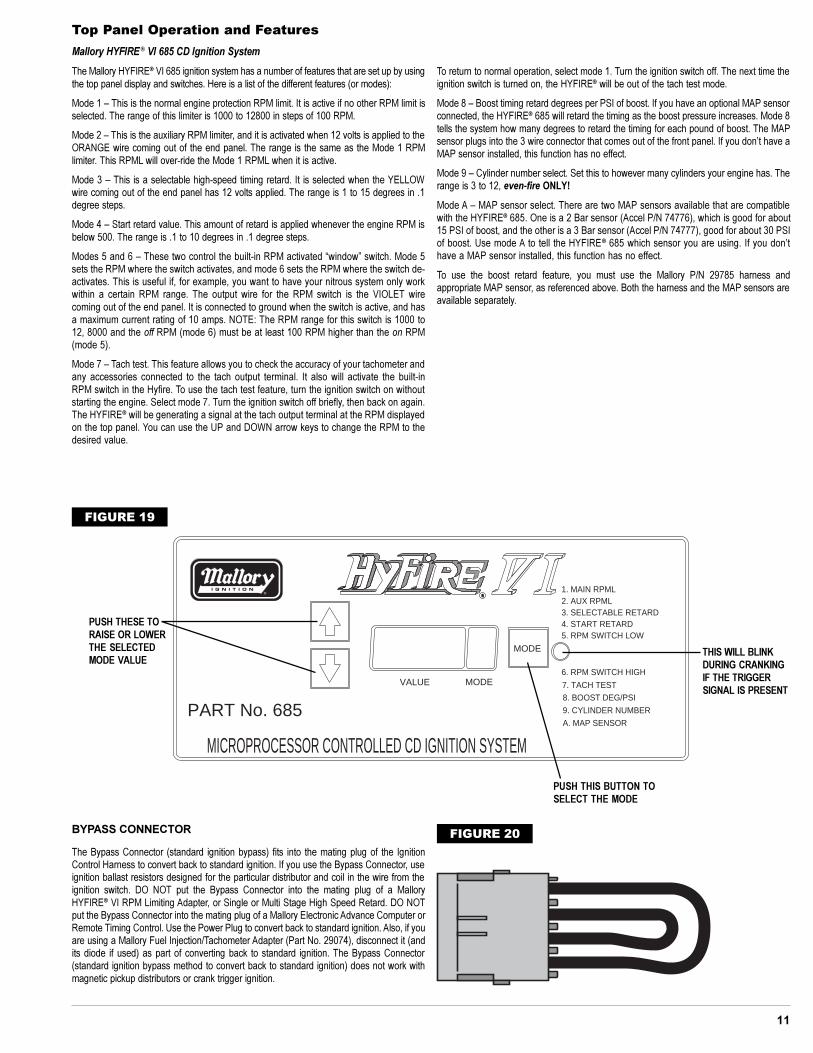
Top Panel Operation and Features
Mallory HYFIRE ® VI 685 CD Ignition System
The Mallory HYFIRE® VI 685 ignition system has a number of features that are set up by usingthe top panel display and switches. Here is a list of the different features (or modes):
Mode 1 � This is the normal engine protection RPM limit. It is active if no other RPM limit isselected. The range of this limiter is 1000 to 12800 in steps of 100 RPM.
Mode 2 � This is the auxiliary RPM limiter, and it is activated when 12 volts is applied to theORANGE wire coming out of the end panel. The range is the same as the Mode 1 RPMlimiter. This RPML will over-ride the Mode 1 RPML when it is active.
Mode 3 � This is a selectable high-speed timing retard. It is selected when the YELLOWwire coming out of the end panel has 12 volts applied. The range is 1 to 15 degrees in .1degree steps.
Mode 4 � Start retard value. This amount of retard is applied whenever the engine RPM isbelow 500. The range is .1 to 10 degrees in .1 degree steps.
Modes 5 and 6 � These two control the built-in RPM activated �window� switch. Mode 5sets the RPM where the switch activates, and mode 6 sets the RPM where the switch de-activates. This is useful if, for example, you want to have your nitrous system only workwithin a certain RPM range. The output wire for the RPM switch is the VIOLET wirecoming out of the end panel. It is connected to ground when the switch is active, and hasa maximum current rating of 10 amps. NOTE: The RPM range for this switch is 1000 to12, 8000 and the off RPM (mode 6) must be at least 100 RPM higher than the on RPM(mode 5).
Mode 7 � Tach test. This feature allows you to check the accuracy of your tachometer andany accessories connected to the tach output terminal. It also will activate the built-inRPM switch in the Hyfire. To use the tach test feature, turn the ignition switch on withoutstarting the engine. Select mode 7. Turn the ignition switch off briefly, then back on again.The HYFIRE® will be generating a signal at the tach output terminal at the RPM displayedon the top panel. You can use the UP and DOWN arrow keys to change the RPM to thedesired value.
To return to normal operation, select mode 1. Turn the ignition switch off. The next time theignition switch is turned on, the HYFIRE® will be out of the tach test mode.
Mode 8 � Boost timing retard degrees per PSI of boost. If you have an optional MAP sensorconnected, the HYFIRE® 685 will retard the timing as the boost pressure increases. Mode 8tells the system how many degrees to retard the timing for each pound of boost. The MAPsensor plugs into the 3 wire connector that comes out of the front panel. If you don�t have aMAP sensor installed, this function has no effect.
Mode 9 � Cylinder number select. Set this to however many cylinders your engine has. Therange is 3 to 12, even-fire ONLY!
Mode A � MAP sensor select. There are two MAP sensors available that are compatiblewith the HYFIRE® 685. One is a 2 Bar sensor (Accel P/N 74776), which is good for about15 PSI of boost, and the other is a 3 Bar sensor (Accel P/N 74777), good for about 30 PSIof boost. Use mode A to tell the HYFIRE® 685 which sensor you are using. If you don�thave a MAP sensor installed, this function has no effect.
To use the boost retard feature, you must use the Mallory P/N 29785 harness andappropriate MAP sensor, as referenced above. Both the harness and the MAP sensors areavailable separately.
BYPASS CONNECTOR
The Bypass Connector (standard ignition bypass) fits into the mating plug of the IgnitionControl Harness to convert back to standard ignition. If you use the Bypass Connector, useignition ballast resistors designed for the particular distributor and coil in the wire from theignition switch. DO NOT put the Bypass Connector into the mating plug of a MalloryHYFIRE® VI RPM Limiting Adapter, or Single or Multi Stage High Speed Retard. DO NOTput the Bypass Connector into the mating plug of a Mallory Electronic Advance Computer orRemote Timing Control. Use the Power Plug to convert back to standard ignition. Also, if youare using a Mallory Fuel Injection/Tachometer Adapter (Part No. 29074), disconnect it (andits diode if used) as part of converting back to standard ignition. The Bypass Connector(standard ignition bypass method to convert back to standard ignition) does not work withmagnetic pickup distributors or crank trigger ignition.
FIGURE 20
MODE
MODEVALUE
MICROPROCESSOR CONTROLLED CD IGNITION SYSTEMA. MAP SENSOR
9. CYLINDER NUMBER
8. BOOST DEG/PSI
7. TACH TEST
6. RPM SWITCH HIGH
5. RPM SWITCH LOW4. START RETARD3. SELECTABLE RETARD2. AUX RPML1. MAIN RPML
PART No. 685
RR®
PUSH THESE TORAISE OR LOWERTHE SELECTEDMODE VALUE
THIS WILL BLINKDURING CRANKINGIF THE TRIGGERSIGNAL IS PRESENT
PUSH THIS BUTTON TOSELECT THE MODE
FIGURE 19
12
MALLORY IS A DVIISION OF THE MR. GASKET PERFORMANCE GROUP550 MALLORY WAY, CARSON CITY, NEVADA 89701(775) 882-6600 FAX (775) 887-4326www.mrgasket.com
FORM 1478(REV. D) 7/00
Made in U.S.A.Printed in U.S.A.
X100X10006 4
CYL
PART No. 6851
RPM
MICROPROCESSOR CONTROLLED CD IGNITION SYSTEM
RR®
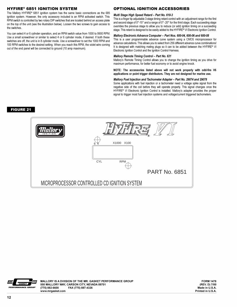
HYFIRE® 6851 IGNITION SYSTEMThe Mallory HYFIRE® 6851 ignition system has the same basic connections as the 685ignition system. However, the only accessory included is an RPM activated switch. ThisRPM switch is controlled by two rotary DIP switches that are located behind an access plateon the top of the unit (see the illustration below). Loosen the two screws to gain access tothe switches.
You can select 4 or 6 cylinder operation, and an RPM switch value from 1000 to 9900 RPM.Use a small screwdriver or similar to select 4 or 6 cylinder mode, if desired. If both theseswitches are off, the unit is in 8 cylinder mode. Use a screwdriver to set the 1000 RPM and100 RPM switches to the desired setting. When you reach this RPM, the violet wire comingout of the end panel will be connected to ground (10 amp maximum).
OPTIONAL IGNITION ACCESSORIES
Multi Stage High Speed Retard � Part No. 618-3This is a finger tip adjustable 3-stage timing retard control with an adjustment range for the firstand second stage of 0°-15° and a range of 0°- 20° for the third stage. Each succeeding stageoverrides the previous stage to allow you to reduce (or add) ignition timing on a succeedingstage. This retard is designed to be easily added to the HYFIRE® VI Electronic Ignition Control.
Mallory Electronic Advance Computer � Part Nos. 600-04, 600-06 and 600-08This is a user programmable advance curve system using a CMOS microprocessor foradvance calculations. This allows you to select from 256 different advance curve combinations!It is designed with matching mating plugs so it can to be added between the HYFIRE® VIElectronic Ignition Control and the Ignition Control Harness.
Mallory Remote Timing Control � Part No. 631Mallory�s Remote Timing Control allows you to change the ignition timing as you drive formaximum performance, for better fuel economy or to avoid engine knock.
NOTE: The accessories listed above will not work properly with odd-fire V6applications or point trigger distributors. They are not designed for marine use.
Mallory Fuel Injection and Tachometer Adapter � Part No. 29074 and 29078Some applications with fuel injection or a tachometer need a voltage spike signal from thenegative side of the coil before they will operate properly. This signal changes once theHYFIRE® VI Electronic Ignition Control is installed. Mallory�s adapter provides the propersignal to trigger most fuel injection systems and voltage/current triggered tachometers.
FIGURE 21