Embed Size (px)
Citation preview
74:5 (2015) 73–76 | www.jurnalteknologi.utm.my | eISSN 2180–3722 |
Full paper Jurnal
Teknologi
Hydrodynamic Resistance analysis of New Hull Design for Multipurpose Amphibious Vehicle Applying with Finite Volume Method M. Nakisaa,c, A. Maimunb*, Yasser M. Ahmeda,d, F. Behrouzia, S. Steene, A. Tarmizia aFaculty of Mechanical Engineering, Universiti Teknologi Malaysia, 81310 UTM Johor Bahru, Johor, Malaysia bMarine Technology Center, Universiti Teknologi Malaysia, 81310 UTM Johor Bahru, Johor, Malaysia cFaculty of Engineering, Islamic Azad University, Boushehr Branch, Boushehr, Iran dFaculty of Engineering, Alexandria University, Alexandria, Egypt eRolls-Royce University Technology Centre , Norwegian University of Science and Technology, N-7491 Trondheim, Norway *Corresponding author: [email protected]
Article history
Received :25 December 2014
Received in revised form : 25 March 2015
Accepted :15 May 2015
Graphical abstract
Multipurpose Amphibious Vehicle
Abstract
This paper numerically investigated the hydrodynamic resistance of Multipurpose Amphibious Vehicles
(MAV) in three bow shapes to approach the better hull bow shape design. This type of vehicle and other blunt-shaped floating vehicles encounter the problem of a large bow wave forming at high speeds. This
wave formation is accompanied by higher resistance and at a critical speed results in bow submergence or
swamping. Three new shapes of hull bow design for the multipurpose amphibious vehicle were conducted at several speeds to investigate the hydrodynamic phenomena using Computational Fluid Dynamics
(CFD, RANS code) which is applied by Ansys-CFX14.0 and Maxsurf. The vehicle’s hydrodynamic bow
shapes were able to break up induced waves and avoid swamping. Comparative results with the vehicle fitted with U-shape, V-shape and Flat-shape of hull bow, showed that the U-shape of the hull bow has
reduced the total resistance to 20.3% and 13.6% compared with the V-shape and flat shape respectively.
Though, the U-shape of hull bow is capable to increase the amphibious operating life and speed of vehicle in calm water. Also it has ability to reduce the vehicle’s required power, fossil fuel consumption and
wetted hull surface.
Keywords: Multipurpose amphibious vehicle; hydrodynamic resistance; RANS code
© 2015 Penerbit UTM Press. All rights reserved.
1.0 INTRODUCTION
The development of landing craft and amphibious vehicles has a
long history beginning in WWII with the Higgins LCVP1
extending to the 35 kt hydrofoil, LVH2, and the 70 kt aircushion
LCAC used today3. Included in this group are the M59
Amphibious Personnel Carrier and the air-transportable M113
Amphibious Personal Carrier introduced in 1960. By 2000, Over
76,000 M113 variants were built4. The M113 is a tracked vehicle
powered by an eight-cylinder 215 hp engine. In the amphibious
operation, the M113 operates at 5.8 km/h (3.13 kt), and on land, it
reaches speeds of 64 km/h. It steers on land and water by
changing the speed of either track. Designed for air transport, the
M113 is compact and lightweight. It has weight saving aluminium
armour plate. The M113 dimensions are 4.86 m long, 2.686 m
wide and 1.85 m high. At its weight of 11,253 kg, it has an
amphibious draft of 1.3 m. The box-shaped hull results in a length
to beam ratio L/B51.80 and a beam to draft ratio B/T52.12. A
study of new hull design of Multipurpose Amphibious Vehicles
(MAV) was conducted to enhance its amphibious capability by
considering floatability, stability and resistance/propulsion
characteristics. Initial resistance and flow visualization simulation
showed that water enters into the driver compartment and that
there is a need for a hydrodynamic bow shape in order to prevent
water build-up at the front of the driver’s place5.
Traditionally, ships have been optimized for minimum fuel
consumption in calm water. For amphibious vehicles, this has led
to very blunt bow shapes. Such bow shapes have high added
resistance due to waves. Thus, one might think that the optimum
bow shape, when realistic wave conditions are taken into account,
should be more slender or hydrodynamic shapes than the current
one. Furthermore, the operational area of the ship (the route it
sails) could influence what is the optimum bow shape.
Amphibious vehicles such as amphibious assault vehicles
and amphibious armoured personnel carriers have been utilized in
the military services for many years6. Their mission specifications
included the amphibious operations described as to be deployed
from a ship in calm to moderate seas and to reach the shore at a
reasonable time. They are usually powered by two water-jets at a
maximum water-borne speed of about 13 km/h. On the other hand
most of these amphibious vehicles are designed for land
operations only and their operations in water are limited to
74 A. Maimun et al. / Jurnal Teknologi (Sciences & Engineering) 74:5 (2015), 73–76
passing through rivers safely at a specified speed without
satisfying floatation requirements. Therefore, the floatability and
stability requirements of these vehicles are optional features
required only for deep river operations.
In the open literature, there are only a few published papers
on the design principles of amphibious vehicles. It is investigated
several waterjet systems for Marine Corps applications7. A flush
type waterjet propulsion unit applied for a Multipurpose
Amphibious Vehicles (MAV) that can cross rivers and lakes at a
speed of 10 km/h with a twin waterjet propulsion system. Self-
propulsion tests were carried out by using a 1/5 scale Amphibious
model to estimate the required effective power. ITTC 96
momentum flux method was utilized to evaluate the performance
of the system. The main parameter on the powering requirement
of the MAV is the impeller size, an increase of 35% in the
waterjet impeller diameter may result in a 38% power reduction,
or a 13% increase in the vehicle speed may be achieved for the
MAV tested8.
2.0 MODELING AND GOVERNING EQUATIONS
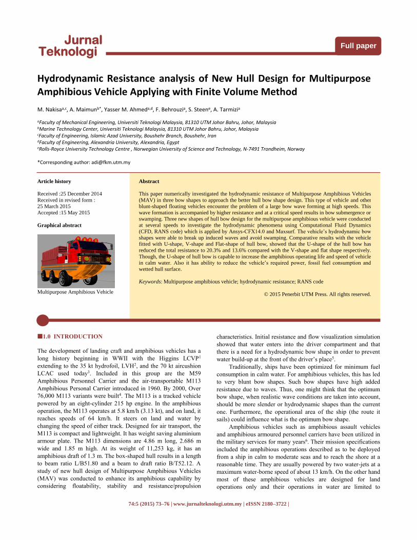
The MAV is equipped with watertight compartments to achieve
floatation capability. The vehicle is also equipped with additional
water pumps in order to pump out the uncontrolled water ingress
during the river crossing mission. Three geometry designs of
MAV are shown in Figures 1-3. The Characteristics of
Multipurpose Amphibious Vehicle are given in Table 1.
Appendages, which are not a part of the main body such as
wheels, drive trains etc. are considered as watertight
compartments and added separately in stability calculations. In
addition to floatability, the vehicle should also be stable in a
floating condition.
(a)
(b) Figure 1 (a) Side view (b) Prespective view of multipurpose amphibious
vehicles
Figure 4 and Table 2 show the computational domain and
mesh elements which is modeled and simulated in analysis-CFX
14.0 using Finite Volume Method (FVM).
Table 1 Characteristics of multipurpose amphibious vehicle
Loading
Condition Actual size
Model
Size Unit
LWL 6.607 1.65175 m
Beam 2.024 0.506 m
Draft 0.99 0.2475 m
Displaced volume 5.314 0.08303 m^3
Wetted area 31.719 0.33212 m^2
Prismatic coeff. 0.559 0.559 ------
Waterplane
area coeff. 0.665 0.665 ------
LCG from midships 2.726 0.6815 m
Transom draft 0.025 0.00625 m
Max sectional area 1.438 0.08987 m^2
Deadrise at
50% LWL 19.33 19.33 deg.
Hard chine or
Round bilge Round bilge
Round
bilge ------
Headwind 0 0 kts
Scale 1 4 ------
Air density 0.001 0.001 tonne/m^3
Kinematic
viscosity 1.1883E-06
1.1883
E-06 m^2/s
Water Density 1.025 1.00 tonne/m^3
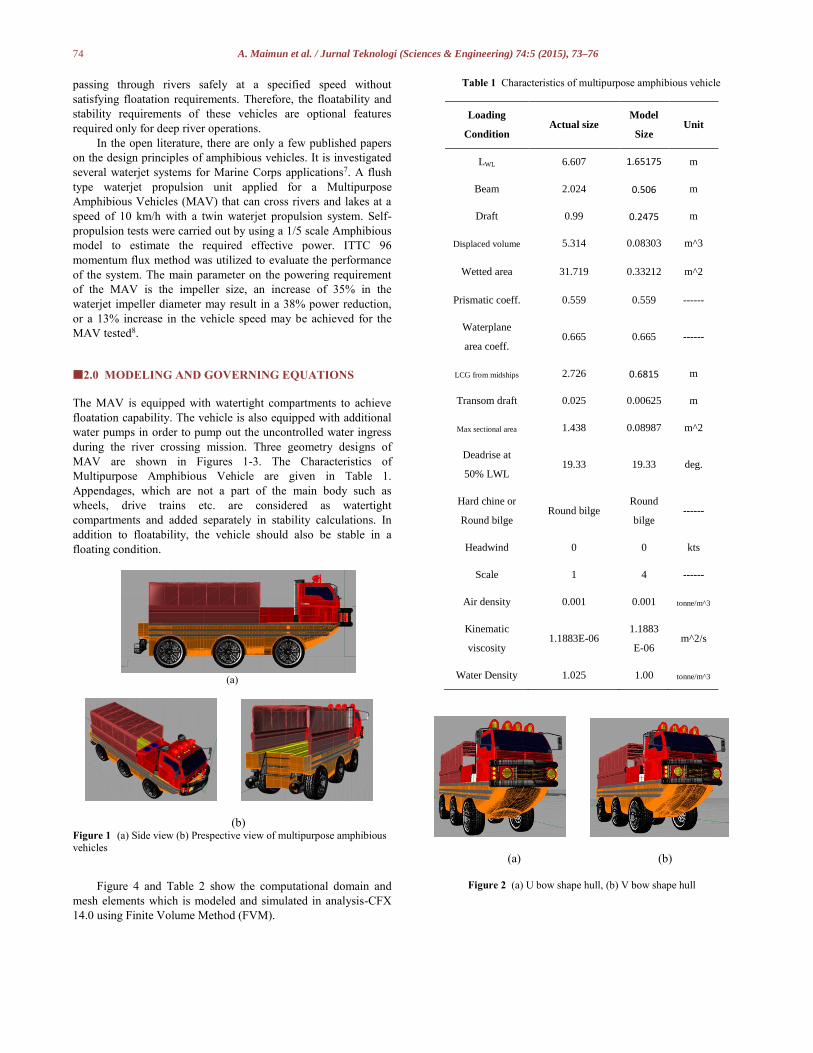
(a) (b)
Figure 2 (a) U bow shape hull, (b) V bow shape hull
75 A. Maimun et al. / Jurnal Teknologi (Sciences & Engineering) 74:5 (2015), 73–76
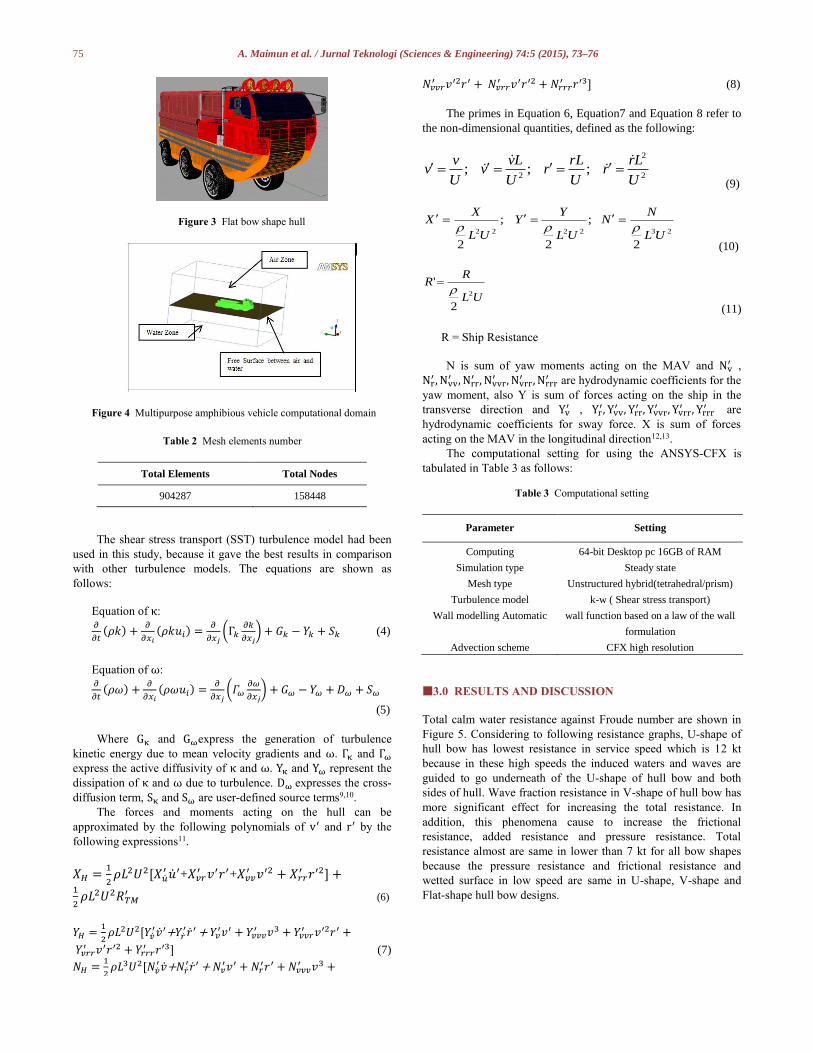
Figure 3 Flat bow shape hull
Figure 4 Multipurpose amphibious vehicle computational domain
Table 2 Mesh elements number
Total Elements Total Nodes
904287 158448
The shear stress transport (SST) turbulence model had been
used in this study, because it gave the best results in comparison
with other turbulence models. The equations are shown as
follows:
Equation of κ: 𝜕
𝜕𝑡(𝜌𝑘) +
𝜕
𝜕𝑥𝑖
(𝜌𝑘𝑢𝑖) =𝜕
𝜕𝑥𝑗(Γ𝑘
𝜕𝑘
𝜕𝑥𝑗) + 𝐺𝑘 − 𝑌𝑘 + 𝑆𝑘 (4)
Equation of ω: 𝜕
𝜕𝑡(𝜌𝜔) +
𝜕
𝜕𝑥𝑖
(𝜌𝜔𝑢𝑖) =𝜕
𝜕𝑥𝑗(𝛤𝜔
𝜕𝜔
𝜕𝑥𝑗) + 𝐺𝜔 − 𝑌𝜔 + 𝐷𝜔 + 𝑆𝜔
(5)
Where Gκ and Gωexpress the generation of turbulence
kinetic energy due to mean velocity gradients and ω. Γκ and Γω
express the active diffusivity of κ and ω. Yκ and Yω represent the
dissipation of κ and ω due to turbulence. Dω expresses the cross-
diffusion term, Sκ and Sω are user-defined source terms9,10.
The forces and moments acting on the hull can be
approximated by the following polynomials of v′ and r′ by the
following expressions11.
𝑋𝐻 =1
2𝜌𝐿2𝑈2[𝑋�̇�
′ �̇�′+𝑋𝑣𝑟′ 𝑣′𝑟′+𝑋𝑣𝑣
′ 𝑣′2 + 𝑋𝑟𝑟′ 𝑟′2] +
1
2𝜌𝐿2𝑈2𝑅𝑇𝑀
′ (6)
𝑌𝐻 =1
2𝜌𝐿2𝑈2[𝑌�̇�
′�̇�′+𝑌�̇�′�̇�′ + 𝑌𝑣
′𝑣′ + 𝑌𝑣𝑣𝑣′ 𝑣3 + 𝑌𝑣𝑣𝑟
′ 𝑣′2𝑟′ +
𝑌𝑣𝑟𝑟′ 𝑣′𝑟′2 + 𝑌𝑟𝑟𝑟
′ 𝑟′3] (7)
𝑁𝐻 =1
2𝜌𝐿3𝑈2[𝑁�̇�
′�̇�+𝑁�̇�′�̇�′ + 𝑁𝑣
′𝑣′ + 𝑁𝑟′𝑟′ + 𝑁𝑣𝑣𝑣
′ 𝑣3 +
𝑁𝑣𝑣𝑟′ 𝑣′2𝑟′ + 𝑁𝑣𝑟𝑟
′ 𝑣′𝑟′2 + 𝑁𝑟𝑟𝑟′ 𝑟′3] (8)
The primes in Equation 6, Equation7 and Equation 8 refer to
the non-dimensional quantities, defined as the following:
2
2
2;;;
U
Lrr
U
rLr
U
Lvv
U
vv
(9)
232222
2
;
2
;
2UL
NN
UL
YY
UL
XX
(10)
UL
RR
2
2
'
(11) R = Ship Resistance
N is sum of yaw moments acting on the MAV and Nv′ ,
Nr′ , Nvv
′ , Nrr′ , Nvvr
′ , Nvrr′ , Nrrr
′ are hydrodynamic coefficients for the
yaw moment, also Y is sum of forces acting on the ship in the
transverse direction and Yv′ , Yr
′, Yvv′ , Yrr
′ , Yvvr′ , Yvrr
′ , Yrrr′ are
hydrodynamic coefficients for sway force. X is sum of forces
acting on the MAV in the longitudinal direction12,13.
The computational setting for using the ANSYS-CFX is
tabulated in Table 3 as follows:
Table 3 Computational setting
Parameter Setting
Computing 64-bit Desktop pc 16GB of RAM
Simulation type Steady state
Mesh type Unstructured hybrid(tetrahedral/prism)
Turbulence model k-w ( Shear stress transport)
Wall modelling Automatic
Advection scheme
wall function based on a law of the wall
formulation
CFX high resolution
3.0 RESULTS AND DISCUSSION
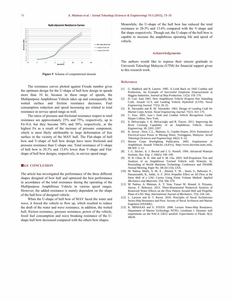
Total calm water resistance against Froude number are shown in
Figure 5. Considering to following resistance graphs, U-shape of
hull bow has lowest resistance in service speed which is 12 kt
because in these high speeds the induced waters and waves are
guided to go underneath of the U-shape of hull bow and both
sides of hull. Wave fraction resistance in V-shape of hull bow has
more significant effect for increasing the total resistance. In
addition, this phenomena cause to increase the frictional
resistance, added resistance and pressure resistance. Total
resistance almost are same in lower than 7 kt for all bow shapes
because the pressure resistance and frictional resistance and
wetted surface in low speed are same in U-shape, V-shape and
Flat-shape hull bow designs.
76 A. Maimun et al. / Jurnal Teknologi (Sciences & Engineering) 74:5 (2015), 73–76
Figure 5 Scheme of computational domain
The resistance curves plotted against Froude number gives
the optimum design for the U-shape of hull bow design in speeds
more than 10 kt, because in these range of speeds, the
Multipurpose Amphibious Vehicle takes up and consequently the
wetted surface and friction resistance decreases. Fuel
consumption reduction and speed increasing are related to total
resistance in service speed range as well.
The ratios of pressure and frictional resistance respect to total
resistance are approximately 25% and 75%, respectively, up to
Fn=0.4, but they become 50% and 50%, respectively, at the
highest Fn as a result of the increase of pressure component,
which is most likely attributable to large deformation of free
surface in the vicinity of the MAV hull. The Flat-shape of hull
bow and V-shape of hull bow design have more frictional and
pressure resistance than U-shape one. Total resistance of U-shape
of hull bow is 20.3% and 13.6% lower than V-shape and Flat-
shape of hull bow designs, respectively, in service speed range.
4.0 CONCLUSION
The article has investigated the performance of the three different
shapes designed of bow hull and optmized the best performance
in accordance of the total resistance during the operating of the
Multipurpose Amphibious Vehicle in various speed ranges.
However, the added resistance is mainly dependent on the shape
of the hull bow of designed vehicle.
When the U-shape of hull bow of MAV faced the water and
wave, it forced the vehicle to flow up, which resulted to reduce
the draft of the water and wave resistance, in addition, the wetted
hull, friction resistance, pressure resistance, power of the vehicle,
fossil fuel consumption and wave breaking resistance of the U-
shape hull bow decreased compared with the others bow shapes.
Meanwhile, the U-shape of the hull bow has reduced the total
resistance to 20.3% and 13.6% compared with the V-shape and
flat shape respectively. Though out, the U-shape of the hull bow is
capable to increase the amphibious operating life and speed of
vehicle.
Acknowledgements
The authors would like to express their sincere gratitude to
Universiti Teknologi Malaysia (UTM) for financial support given
to this research work.
References [1] G. Haddock and R. Latorre. 1995. A Look Back on 1942 Combat and
Production, An Example of Successful Employee Empowerment at
Higgins Industries. Journal of Ship Production. 11(3): 159–170.
[2] D. Carl. June 1965. New Amphibious Vehicle Progress Part 3nlanding
Craft, Assault LCA and Landing Vehicle Hydrofoil (LVH). Naval
Engineering Journal. 77(3): 18–25.
[3] R. Alexander and R. M. Alexander. 1963. Design of Landing Craft for
Marine Corps Action. Naval Engineering Journal. 75(1): 163–170.
[4] C. Foss. 2003. Jane’s Tank and Combat Vehicle Recognition Guide. Harper Collins, New York.
[5] S. Helvacioglu, I. H. Helvacioglu and B. Tuncer. 2011. Improving the
River Crossing Capability of an Amphibious Vehicle. Ocean
Engineering. 38: 2201–2207.
[6] K. Jaswar , Siow, C.L., Maimun, A., Guedes Soares. 2014. Estimation of
Electrical-wave Power in Merang Shore, Terengganu, Malaysia. Jurnal
Teknologi (Sciences and Engineering). 66(2): 9–14.
[7] Marine Corps Warfighting Publication. 2005. Employment of Amphibious Assault Vehicles (AAVs), /http://www.doctrine.usmc.mils,
MCWP. 3–13.
[8] J. G. Sticker, A. J. Becnel and J. G. Purnell. 1994. Advanced Waterjet
Systems. Nav. Eng. J. 106(5): 100–109.
[9] H. H. Chun, B. H. Ahn and S. M. Cha. 2003. Self-Propulsion Test and
Analysis of an Amphibious Tracked Vehicle with Waterjet. In:
Proceeding of World Maritime Technology Conference and SNAME Annual Meeting, Paper No. D6 (D-133), USA.
[10] M. Nakisa, Malik, A. M. A , Ahmed, Y. M. , Steen, S., Behrouzi, F.,
Hassanzadeh, R., Sabki, A. F. 2014. Propeller Effect on 3D Flow at the
Stern Hull of a LNG Carrier Using Finite Volume Method. Applied
Mechanics and Materials. 554: 566–570.
[11] M. Nakisa, A. Maimun, A. Y. Sian, Yasser M. Ahmed, A. Priyanto,
Jaswar, F. Behrouzi. 2013. Three-dimensional Numerical Analysis of
Restricted Water Effects on the Flow Pattern Around Hull and Propeller Plane of LNG Ship. International Journal of Mechanics. 7(3): 234–241.
[12] L. Larsson and H. C Raven. 2010. Principles of Naval Architecture
Series-Ship Resistance and Flow. Society of Naval Architects and Marine
Engineers (SNAME).
[13] K. MINSAAS and S. STEEN. 2008. Lecture Notes-Ship Resistance,
Department of Marine Technology–NTNU, Leishman J. Dynamic stall
experiments on the NACA 23012 aerofoil. Experiments in Fluids. 9(1): 49e58.