Embed Size (px)
Citation preview

www.hydro-mobile.com
REVISION LIST
Date DescriptionMay 2013 v1.0 First edition of Owner’s manual
GENERAL INFORMATION
Motorized unit serial number
Manufacturing date
GENERAL INFORMATION
© 2013 by Hydro Mobile Inc. All rights reservedThis manual was produced by Hydro Mobile Inc. on Adobe® InDesign CS5.5® for Windows®.Technical drawings were prepared using Autodesk Inventor ® 2008. Illustrations were created with Autodesk® 3ds Max®, Autodesk Inventor ® 2008, Adobe® Illustrator CS5.1® for Windows® and Adobe® Photoshop CS5.1® for Windows®.This manual may not, in whole or in part, be copied, photocopied, reproduced, translated, or converted to any electronic or machine readable form without prior written consent of Hydro Mobile Inc.
NOTE
All assembly and operation instructions located on motorized units and bridges take precedence over information contained in this manual. Should there be any discrepancies discovered throughout any published documentation issued by Hydro Mobile or its authorized affi liates, the following order of precedence shall prevail:
1. Written documents issued by the Hydro Mobile Engineering department2. Recall instructions3. Assembly or operation instructions displayed on the motorized unit4. Owner’s manual
Any use of one or several Hydro Mobile motorized units, with or without accessories, in such a confi guration or manner as not explicitly described in this manual is not recommended without the prior written permission of Hydro Mobile Inc.
125 de l’IndustrieL’Assomption, Quebec, Canada
J5W 2T9
For orders or information:1-888-484-9376 (US)
(toll free in the United States)450 589-8100 (Canada)
LEGEND OF ICONSThese icons are used to highlight important information throughout this manual
Walkthrough stepsInstallation or confi guration steps, at a glance
Warning noteAn important warning: damage or injury may occur
Wind speed warningAn important warning: wind speed conditions must be observed to avoid damage or injury
Useful tipA useful tip to facilitate installation or operation
InformationUseful information for safe and easy operation

3
Introduction .....................................................4Warranty .........................................................5
Performance and safety rules.........................6
Overview.........................................................8List of components included ...........................8Toolbox components.......................................8Specifi cations ...............................................10Weight of components ..................................12Dimensions ...................................................13Positioning Suggested cribbing .............................14 Minimum bearing surface capacities ...14Setup and confi gurations General guidelines ..............................15 Standard installation (single unit with mast ties) ...................15 Multiple unit installation (with mast ties) ....................................18
Emergency descent control system..............20 Installation of the feedback cable ........20Inclinometer ..................................................22 Adjustment of the 0 degree position ....22
Standard bridge Installation ...........................................23Bridge types..................................................23Cantilever bridge Installation ...........................................24Bearing bridge Installation ...........................................25Twin mast adapter Installation ...........................................26Forward/backward extension Installation ...........................................27Bridge deck extension Installation ...........................................28Swivel bridge Installation ...........................................29 Angle adjustment ................................29 Front cantilever confi guration ..............31 Back cantilever confi guration ..............32 Front bearing bridge confi guration ......33 Back bearing bridge confi guration .......35 Counterweight adapter ........................37 Outrigger support assembly ................39
General guidelines........................................40Power cable selection chart..........................40Installation of the power cable Setups of 150' (30,5 m) or less ...........41 Setups over 150' (30,5 m) ...................41Motorized unit startup procedure ..................42Motorized unit shutdown procedure .............42
Description....................................................43Controls ........................................................44Screen alerts and instructions Unlocking the display screen ..............44 Main menu screen ...............................45 F1 – Status info ...................................45 F2 – Alerts ...........................................46 F3 – Inputs and outputs ......................48 F4 – Confi guration ...............................48
Mast sections Installation ...........................................50 Lifting capacity of the mast head .........51 Storage and transport .........................51Mast ties Mast tie schedule ................................52 Pre-installation instructions .................52 Confi gurations during normal operation .............................................52 Installation of the anchoring system ....53 Installation of standard mast ties .........53 Installation of mast tie extensions .......55 Additional rigid dual clamps ................55
Load capacity calculation guidelines ............56Single unit installation ...................................57Multiple units installation...............................58Back / forward extension installation ............59Swivel bridge installation Single unit (0-45 degrees) ...................59 Single unit (90 degrees) ......................60 Multiple units .......................................61 With counterweight adapter ................62Hoist installation Single unit setup ..................................64 Multiple units setup .............................65
Bridge installation support bracket ...............66Universal plank safety support .....................66Outriggers Outrigger selection table .....................67 Planking confi guration guidelines ........67 Outriggers – top position .....................68 Outriggers – bottom position ...............68 Doubled outriggers ..............................69Cross boxes..................................................70Guardrails Installation ...........................................70 Guardrail adapter L bracket .................70 Movable guardrail ................................71 Plank-end guardrail .............................71 Face guardrail bracket ........................71Access stairs ................................................72Jib arm ..........................................................73Hoist support assembly ................................74Cable trolley..................................................75
Transport and storage ..................................77Maintenance .................................................78 Greasing of rack and gears .................78 Inspection checklists ...........................79
General InformationGeneral Information
Performance and SafetyPerformance and Safety
1 – Motorized Unit1 – Motorized Unit
3 – Bridges3 – Bridges
4 – Power Pack and Components4 – Power Pack and Components
7 – Load Capacities7 – Load Capacities
5 – Control Panel5 – Control Panel
6 – Masts and Mast Ties6 – Masts and Mast Ties
8 – Accessories8 – Accessories
2 – Safety Devices2 – Safety Devices
9 – Transport, Storage and Maintenance9 – Transport, Storage and Maintenance
GENERAL INFORMATION
Table of Contents

Introduction
GENERAL INFORMATION
Dear owner or user:
Thank you for investing in a Hydro Mobile S Series mast climbing work platform system. The design of this motorized unit refl ects over a decade of continued fi eld operation, testing and research work and comes as a solution to our company’s deepest concern, your safety and well being on the job.
To ensure that the workplace becomes safer and more effi cient using a Hydro Mobile system, always have a competent person and backup competent person assemble, operate, dismantle and move your mast climbing work platform system. These competent persons will be required to read this owner’s manual and assimilate the information contained herein. Failure to do so could lead to serious injury and/or equipment damage.
These motorized units were designed in accordance with the following standards: US ANSI A92.9-2011, ISO 16369:2007 and EN 1495, 98/37/CE "directive machine" and 89/336/CEE "directive CEM". Furthermore, these motorized units and their owner’s manual comply with US ANSI A92.9-2011 standards, Federal Occupational Safety and Health Administration Standards OSHA 29CFR1926 subpart L; with ISO 16369:2007 and CSA B354.5-07; and with EN 1495, 98/37/CE "directive machine", 89/336/CEE "directive CEM" and ISO 16369:2007.
To maximize the life expectancy of your equipment and to enjoy years of trouble free operation, we recommend that this Hydro Mobile system be serviced according to maintenance schedules and recommendations provided in this manual.
Should you have any questions or concerns, please contact the nearest authorized service center or Hydro Mobile directly at 888-484-9376 (in the United States), 450-589-8100 (in Canada). You can also visit our Web site at www.hydro-mobile.com for additional support and information on our factory safety and performance training seminars.
We wish you years and years of safe, productive construction and renovation work.
Sincerely,
Vincent Dequoy, Eng.President
The installation and operation of a mast climber is subject to hazards that can be avoided only by using extreme care and common sense.
It is essential that the competent person be properly trained in the installation, dismantling, proper use and safe operation of the mast
climber and its accessories.

5
Warranty
GENERAL INFORMATION
Warranty period
Hydro Mobile Inc., herein referred to as Hydro Mobile, warrants its new S Series motorized units to be free from defect of materials and workmanship for a period of 15 months from the date of delivery to the authorized service center.Hydro Mobile also warrants its new S Series parts and accessories to be free from defect of materials and workmanship for a period of 15 months from the date of delivery to the authorized service center.
Product registration
The owner of a Hydro Mobile S Series unit should register the product with Hydro Mobile by fi lling out and returning the warranty registration form included in the owner’s manual.
Description of warranty
Hydro Mobile’s obligation and liability under this warranty are expressly limited to repairing or replacing with re-manufactured or new parts, at Hydro Mobile’s option, any part and accessory manufactured by Hydro Mobile proven defective after inspection by Hydro Mobile which appear to have been defective in material or workmanship. Only permanent repairs will be covered under this warranty. Hydro Mobile reserves the right to ask for maintenance records of the defective part before settling a claim and to deny such claim if maintenance records are not available or not compliant with maintenance schedules. This warranty shall not apply to component parts or accessories of products not manufactured by Hydro Mobile and which carry the warranty of the manufacturer thereof or to normal maintenance (such as engine tune-up) or any part necessary to perform such maintenance. Hydro Mobile offers no other warranty, expressed or implied, and offers no warranty of merchantability or fi tness for any particular purpose.
Parts and accessories manufactured by Hydro Mobile
All motors and gear boxes manufactured by Nord Gear Limited are covered by an international warranty of 15 months. To have a motor or a gear box repaired under this warranty, the motor or gear box must be brought to an authorized Hydro Mobile service center.
Motor
Hydro Mobile’s obligation under such warranty shall not include duty, taxes or any other charge whatsoever, or any liability for direct, indirect, incidental or consequential damage or delay.
Costs and liability associated with warranty
Any use of one or several Hydro Mobile motorized units, with or without accessories, in such a confi guration or manner as not explicitly described in the owner’s manual is not recommended without the prior written permission of Hydro Mobile.Any improper use, including operation after discovery of defective or worn parts, shall void this warranty. Improper use also includes operation beyond rated capacity, substitution of parts other than those approved by Hydro Mobile, including anchor systems, or any alteration, modifi cation or repair by others in such manner as in Hydro Mobile’s judgment affects the product materially and adversely.
Exclusion
All warranty work must be performed by a certifi ed Hydro Mobile technician to be eligible for reimbursement under the warranty.
Labor

6
PERFORMANCE AND SAFETY
1- Prepare a layout plan showing how the mast climbing work platform system [motorized unit(s), bridges, extensions] will be positioned near structures or walls to be erected. On long walls, separate mast climber sections to allow for fl exibility. Position motorized units to provide proper anchoring points for masts.2- Establish the distance between the mast climbing work platform system and the structure or wall, taking into account the length of plank outriggers, as well as curvatures, balconies, columns, trees, telephone wires, electrical lines, etc. 3- Refer to and follow regulations governing distances between the mast climbing work platform system and electrical lines.4- Make sure the ground or support surface capacity meets with values included in the Minimum Bearing Surface Capacities table herein (fi g. 1.9, p. 14). Soil compacting, cribbing or shoring can increase bearing capacity. The jacks on the base extensions are designed to level the motorized unit and should not be used to support the load nor the motorized unit. Contact a licensed engineer for assistance. 5- Never modify the mast climbing work platform system or use substitute factory parts. This could adversely affect worker safety, unit performance and void the warranty. In addition, this could lead to serious injury or death. 6- Unless authorized in writing by Hydro Mobile prior to installation, the motorized unit must not be used with any equipment or any accessories (hoist, weather protection, monorail, etc.) not specifi cally manufactured and rated by Hydro Mobile to be used with S Series motorized units. For the use and installation of any such equipment or accessories, contact the service center or the Hydro Mobile technical support team. 7- Planks used for planking must be scaffold graded (SPF) and in good condition. 8- IMPORTANT: It is strongly recommended not to use equipment that may generate excessive vibrations or reactions on Hydro Mobile platforms.9- Workers exposed to potential hazards must always wear proper personal protection equipment (PPE) such as a helmet, safety boots, a fall arrest harness, etc., as prescribed by local regulations. In all cases where workers are exposed to fall hazards, fall protection is required. Installation of all the necessary guardrails is mandatory. Tie points (D-rings) located on the main trolley of the motorized unit (fi g. 1.4, p. 9) are designed to resist to 5000 lb (2268 kg) and can be used by workers to tie themselves to the unit (not more than one worker per D-ring).
Performance and Safety RulesSAFETY comes fi rst. The installation and operation of a mast climber is subject to hazards that can be avoided only by using extreme care and common sense, and by providing the appropriate training and supervision to all its users. It is essential that the installation and dismantling of the S Series motorized unit and its related accessories be carried out according to the recommendations of the owner’s manual and performed under the supervision of a competent person. It is also imperative that the operation of an S Series motorized unit setup be carried out according to the recommendations of the owner’s manual. To ensure safe and proper operation, it is suggested that two persons be on hand to perform maneuvers for each motorized unit in a setup.
Operating instructions
The competent person, referred to throughout this owner’s manual and related documentation, is a person recognized by international safety standards as having the theoretical knowledge and the experience on the S Series motorized unit and
its accessories to be capable of identifying existing and predictable hazards on and around the job site and in the working conditions that could seriously compromise
the safety of workers or cause damages to the equipment, and who has the authority to take prompt, corrective measures to eliminate such hazards.
Defi nition of the competent person

7
PERFORMANCE AND SAFETY
Performance and Safety Rules
10- Unless authorized by Hydro Mobile prior to installation, the platform should only be used on masts whose height does not exceed 500' (152 m). For any confi guration other than those described in this owner’s manual, contact the Hydro Mobile technical support team. The use of the optional cable trolley kit is recommended for setups higher than 150' (30,5 m).11- Rely on a licensed engineer for help on special jobs and to approve plans if required by local regulation. 12- To ensure work effi ciency, maintain an adequate equipment and parts inventory on the job site. Keep equipment in good condition. Refer to inspection and maintenance checklists recommended for this motorized unit (see p. 79). Inspection and maintenance operations must be carried out by an authorized technician, specifi cally trained on the S Series motorized unit and its accessories. 13- After installation, mark off limit areas of the system using fencing, barriers, warning tape and note emergency phone numbers (fi re and police dept.) for quick reference. Prepare an emergency evacuation plan that is specifi c to the job site and is in accordance with local regulations. 14- Never load bridges or motorized units beyond their rated capacities. Overloading may cause damages to equipment leading to serious injury or death. 15- Contact the service center or Hydro Mobile for service, repair or technical advice. Refer to equipment type and serial number when calling. 16- Each person should access the platform by the access stairs, a staircase or through an opening in the building. In all cases, transfer must be safe and free from obstruction.17- The use of appropriate fall protection equipment is mandatory when modifying plank confi guration. Failure to use fall protection equipment can expose the user to serious injury or death. 18- When the motorized unit is moving, it is mandatory that all workers except the operator stand in an area close to the back guardrails. 19- In the event of an abnormal occurrence or operation which could compromise security (ex. malfunction of a motorized unit component, collision with an obstacle, etc.), immobilize the unit and inform the competent person.20- It is strongly recommended not to touch any of the moving parts on the motorized unit when it is in use. 21- All access doors on the motorized unit must be closed when they are not in use.22- To ensure safe and proper operation, it is suggested that there be two persons for each motorized unit in a setup.23- The motorized unit must not be used or operated during an electrical thunderstorm. The motorized unit and its components must not be used as ground for electrical connections. 24- The deposit of loads on the setup must be done with extreme care, under proper supervision. Loads must be distributed on all the bridges of the setup, as prescribed by the load capacities charts. Refer to the Load Capacities section on p. 56 for more information about loading the platform. When the motorized unit setup is not in use and is above base level, loads should not be left on the platform.25- In the event of a power outage, it is recommended that all workers remain on the platform as a safety precaution until the power is restored. If the power has not been restored within a reasonable time, the emergency descent system must be used to bring the workers safely back to the nearest safe evacuation point. Refer to p. 20 of the Safety Devices section for more information on the use of the emergency descent system. 26- Wind speeds must not exceed 28 mph (45 km/h) during the erection and dismantling of a motorized unit setup (including the base, the bridges, the masts, the mast ties and all the other components). Freestanding installations, when allowed, and setups equipped with weather protection must not be exposed to wind speeds exceeding 28 mph (45 km/h). A motorized unit setup with mast ties must not be exposed to wind speeds exceeding 35 mph (56 km/h) when in operation. Wind speeds must not exceed 102 mph (164 km/h) when the motorized unit setup is not in use.
8
Fig. 1.2
Fig. 1.1
Fig. 1.3
1 - MOTORIZED UNIT
Door guardrail
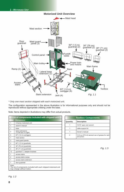
Motorized Unit Overview
List of components included with shipped unitList of components included with shipped unitQty Component1 S Series motorized unit
1 owner’s manual
1 base
2 base extensions (1x left and 1x right)
4 63" (1,6 m) outriggers
1 mast section
3 mast guard panels
2 60" (1,5 m) guardrails
2 30" (76 cm) guardrails
2 28” (71 cm) guardrails
12 guardrail “L” adapter brackets
1 access stairs
2 access stairs ramps
1 access stairs extension
1 door guardrail
NoteThe list of components included with each shipped motorized unit may change without notice.
The confi guration represented in the above illustration is for informational purposes only and should not be reproduced without appropriate cribbing under the base.
Note: Items depicted in illustrations may differ from actual products.
* Only one mast section shipped with each motorized unit.
Ramp (2)
Stairs extension
Access stairs
Mast section
Mast guard panel (3)
Control panel
Lateral base extension (2)
Jack (4)
Base
Main trolley Power train and motors
Main frame
60" (1,5 m) guardrail (2)
63" (1,6 m) outrigger (4)
30" (76 cm) guardrail (2) 28" (71 cm)
guardrail (2)
Mast head
Forklift tubes
Toolbox
Toolbox ComponentsQuantity Description
1 15/16” open end wrench
1 cable support kit
1 Owner’s manual
2 12,5 oz (370 ml) aerosol can of grease for rack and pinion
9
Fig. 1.4
Fig. 1.5FFigFF
Fig. 1.6iigFiFiFi
Fig. 1.7
Fig. 1.8
1 - MOTORIZED UNIT
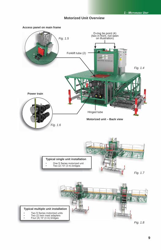
Motorized Unit Overview
Motorized unit – Back view
Access panel on main frame
Power train
Typical single unit installation• One S Series motorized unit• Two (2) 10' (3 m) bridges
Typical multiple unit installation• Two S Series motorized units• Two (2) twin mast adapters• Four (4) 10' (3 m) bridges
D-ring tie point (4)(two in front, not seen
on illustration)
Forklift tube (2)
Hinged tube
10
Fig. 1.9
Fig. 1.10
1 - MOTORIZED UNIT
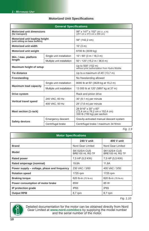
Motorized Unit Specifi cations
General Specifi cationsMotorized unit dimensions(for transport)
99" x 147" x 102" (W x L x H)(251 cm x 373 cm x 259 cm)
Motorized unit loading height (unit sitting on base buffers) 56" (142,2 cm)
Motorized unit width 10' (3 m)
Motorized unit weight 6700 lb (3039 kg)
Min. / max. platform length
Single unit installation 10' / 60' (3 m / 18,3 m)
Multiple unit installation 50' / 120' (15,2 m / 36,6 m)
Maximum height of setup Up to 500' (152 m)without prior authorization from Hydro Mobile
Tie distance Up to a maximum of 45' (13,7 m)
Freestanding No freestanding allowed
Maximum load capacitySingle unit installation 8000 lb at 50' (3629 kg at 15,2 m)
Multiple unit installation 13 000 lb at 120' (5897 kg at 37 m)
Drive system Rack and pinion drive
Vertical travel speed240 VAC, 60 Hz 30' (9,1 m) per minute
400 VAC, 50 Hz 25' (7,6 m) per minute
Mast section (1-rack)28 9/16" x 30" x 60"(72,4 cm x 76,2 cm x 152,4 cm)330 lb (150 kg) per section
Safety devicesEmergency descent Gravity-activated manual descent system
Centrifugal brake Centrifugal brake / maximum 34 ft/min
Motor Specifi cations
240 V unit 400 V unit
Brand Nord Gear Limited Nord Gear Limited
Model SK132S/4 CUS BRE100 HL RG TF
SK132S/4 CUS BRE100 HL RG TF
Rated power 7,5 HP (5,5 KW) 7,5 HP (5,5 KW)
Rated amperage (nominal) 19,8A 11,8A
Power supply – voltage, phase and frequency 230 VAC / 3/60 400 VAC / 3/50
Rotation speed 1725 rpm 1725 rpm
Braking torque 620 lb-in (70 N-m) 620 lb-in (70 N-m)
Power consumption of motor brake 85W 85 W
IP protection grade IP65 IP65
Output RPM 8,7 rpm 8,7 rpm
Detailed documentation for the motor can be obtained directly from Nord Gear Limited at www.nord.com/docs by supplying the model number
and the serial number of the motor.
11
Fig. 1.11
Fig. 1.12
Fig. 1.13
Fig. 1.14
1 - MOTORIZED UNIT
Motorized Unit Specifi cations
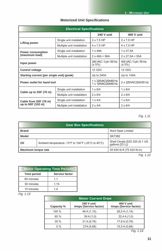
Electrical Specifi cations240 V unit 400 V unit
Lifting powerSingle unit installation 2 x 7,5 HP 2 x 7,5 HP
Multiple unit installation 4 x 7,5 HP 4 x 7,5 HP
Power consumption(maximum load)
Single unit installation 1 x 48A 1 x 27,5A
Multiple unit installation 2 x 48A = 96A 2 x 27,5A = 55A
Input power 240 VAC / 3 ph / 60 Hz(± 5%)
400 VAC / 3 ph / 50 Hz(± 5%)
Control voltage 12 VDC 12 VDC
Starting current (per single unit) (peak) Up to 240A Up to 140A
Power outlet for hand tool 1 x 220VAC/20A/60 Hz1 x 120VAC/20A/60 Hz 2 x 220VAC/20A/50 Hz
Cable up to 250' (76 m)Single unit installation 1 x 6/4 1 x 8/4
Multiple unit installation 2 x 6/4 2 x 8/4
Cable from 250' (76 m)up to 500' (152 m)
Single unit installation 1 x 4/4 1 x 6/4
Multiple unit installation 2 x 4/4 2 x 6/4
Gear Box Specifi cationsBrand Nord Gear Limited
Model SK7382
Oil Ambient temperature -13°F to 104°F (-25°C to 40°C) Shell Omala S2G 220 (6.1 US gallons [23 L])
Maximum torque rate 55 630 lb-ft (75 424 N-m)
Motor Operating Time PeriodsTime period Service factor
60 minutes 1,1
30 minutes 1,15
10 minutes 1,4
Motor Current Draw
Capacity %240 V unit
Amps (Service factor)400 V unit
Amps (Service factor)
100 % 46 A (1,15) 26,5 A (1,15)
65 % 39 A (1,0) 22,4 A (1,0)
35 % 31 A (0,76) 17,8 A (0,76)
0 % 27A (0,68) 15,5 A (0,68)
12
Fig. 1.15
Fig. 1.16
1 - MOTORIZED UNIT
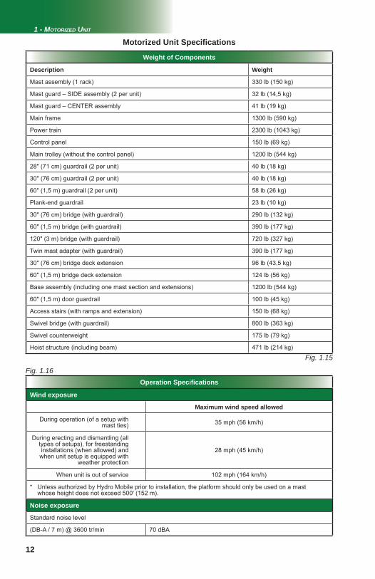
Operation Specifi cations
Wind exposure
Maximum wind speed allowed
During operation (of a setup with mast ties) 35 mph (56 km/h)
During erecting and dismantling (all types of setups), for freestanding installations (when allowed) and
when unit setup is equipped with weather protection
28 mph (45 km/h)
When unit is out of service 102 mph (164 km/h)
* Unless authorized by Hydro Mobile prior to installation, the platform should only be used on a mast whose height does not exceed 500' (152 m).
Noise exposure
Standard noise level
(DB-A / 7 m) @ 3600 tr/min 70 dBA
Weight of Components
Description Weight
Mast assembly (1 rack) 330 lb (150 kg)
Mast guard – SIDE assembly (2 per unit) 32 lb (14,5 kg)
Mast guard – CENTER assembly 41 lb (19 kg)
Main frame 1300 lb (590 kg)
Power train 2300 lb (1043 kg)
Control panel 150 lb (69 kg)
Main trolley (without the control panel) 1200 lb (544 kg)
28" (71 cm) guardrail (2 per unit) 40 lb (18 kg)
30" (76 cm) guardrail (2 per unit) 40 lb (18 kg)
60" (1,5 m) guardrail (2 per unit) 58 lb (26 kg)
Plank-end guardrail 23 lb (10 kg)
30" (76 cm) bridge (with guardrail) 290 lb (132 kg)
60" (1,5 m) bridge (with guardrail) 390 lb (177 kg)
120" (3 m) bridge (with guardrail) 720 lb (327 kg)
Twin mast adapter (with guardrail) 390 lb (177 kg)
30" (76 cm) bridge deck extension 96 lb (43,5 kg)
60" (1,5 m) bridge deck extension 124 lb (56 kg)
Base assembly (including one mast section and extensions) 1200 lb (544 kg)
60" (1,5 m) door guardrail 100 lb (45 kg)
Access stairs (with ramps and extension) 150 lb (68 kg)
Swivel bridge (with guardrail) 800 lb (363 kg)
Swivel counterweight 175 lb (79 kg)
Hoist structure (including beam) 471 lb (214 kg)
Motorized Unit Specifi cations
13
Fig. 1.18
Fig. 1.17
1 - MOTORIZED UNIT
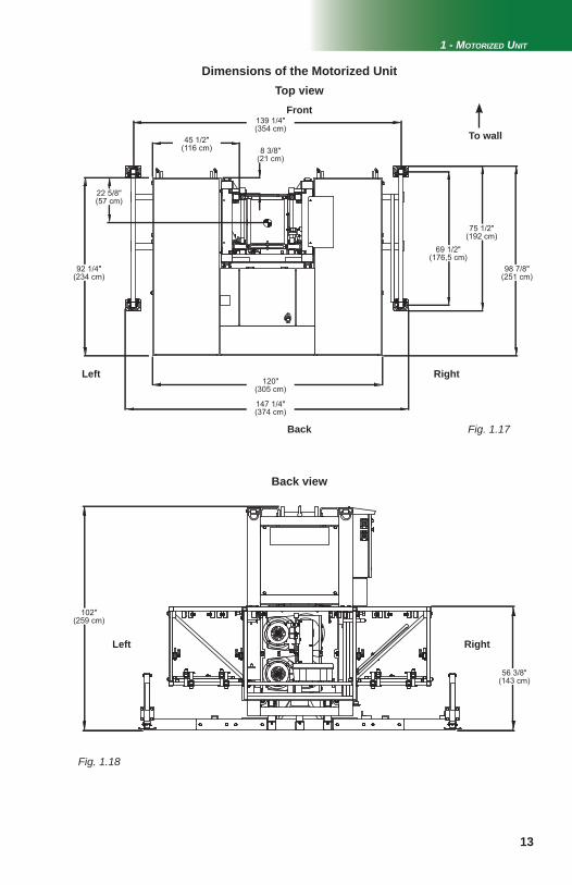
Dimensions of the Motorized Unit
Front
To wall139 1/4"(354 cm)
Back
Left
Top view
Back view
Right
Left Right
45 1/2"(116 cm) 8 3/8"
(21 cm)
92 1/4"(234 cm)
69 1/2"(176,5 cm)
75 1/2"(192 cm)
98 7/8"(251 cm)
120"(305 cm)
147 1/4"(374 cm)
102"(259 cm)
56 3/8"(143 cm)
22 5/8"(57 cm)
14
1
2
1
2
1
2
1
Fig.1.20
Fig. 1.21
Fig.1.19
1 - MOTORIZED UNIT
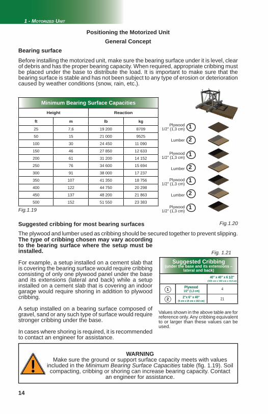
Positioning the Motorized Unit
Bearing surfaceBefore installing the motorized unit, make sure the bearing surface under it is level, clear of debris and has the proper bearing capacity. When required, appropriate cribbing must be placed under the base to distribute the load. It is important to make sure that the bearing surface is stable and has not been subject to any type of erosion or deterioration caused by weather conditions (snow, rain, etc.).
General Concept
Plywood1/2” (1,3 cm)
Lumber
Plywood1/2” (1,3 cm)
Lumber
Plywood1/2” (1,3 cm)
Lumber
Plywood1/2” (1,3 cm)
Suggested Cribbing(under the base and its extensions –
lateral and back)40” x 40” x 6 1/2”
(102 cm x 102 cm x 16,5 cm)
Plywood 1/2” (1,3 cm) 4
2”x 6” x 40”(5 cm x 15 cm x 102 cm) 21
Suggested cribbing for most bearing surfacesThe plywood and lumber used as cribbing should be secured together to prevent slipping.
Values shown in the above table are for reference only. Any cribbing equivalent to or larger than these values can be used.
The type of cribbing chosen may vary according to the bearing surface where the setup must be installed.
For example, a setup installed on a cement slab that is covering the bearing surface would require cribbing consisting of only one plywood panel under the base and its extensions (lateral and back) while a setup installed on a cement slab that is covering an indoor garage would require shoring in addition to plywood cribbing.
A setup installed on a bearing surface composed of gravel, sand or any such type of surface would require stronger cribbing under the base.
In cases where shoring is required, it is recommended to contact an engineer for assistance.
WARNINGMake sure the ground or support surface capacity meets with values
included in the Minimum Bearing Surface Capacities table (fi g. 1.19). Soil compacting, cribbing or shoring can increase bearing capacity. Contact
an engineer for assistance.
Minimum Bearing Surface Capacities
Height Reaction
ft m lb kg
25 7,6 19 200 8709
50 15 21 000 9525
100 30 24 450 11 090
150 46 27 850 12 633
200 61 31 200 14 152
250 76 34 600 15 694
300 91 38 000 17 237
350 107 41 350 18 756
400 122 44 750 20 298
450 137 48 200 21 863
500 152 51 550 23 383
2
1
15
1 - MOTORIZED UNIT
General Guidelines
Setup and Confi gurations
1- Installation should be carried out under the supervision of a competent person, in accordance with all applicable local regulations.
2- In reference to the plan/layout drawing, make sure that all the components required are available. Establish the position of the motorized unit, determine if there are obstacles and what are the cribbing requirements.
3- Before installing the motorized unit, determine where the cribbing under the base and its extensions (lateral and back) will rest. The bearing surface under the cribbing should be level, clear of debris and have the proper bearing capacity (see the Minimum Bearing Surface Capacities table, fi g. 1.19, p. 14). Should the actual bearing capacity be inferior to the values in the table, please seek instructions and recommendations from Hydro Mobile. It is important to note that the jacks on the base extensions are designed to level the motorized unit and should not be used to support the load nor the motorized unit.
4- Distance from the fi nished wall should be the number of planks multiplied by the width of one plank, while allowing 6" to 8" (15 to 20 cm) of play. Add an additional 2" (5 cm) if using a toe board. Refer to applicable local regulations to determine play or the maximum allowable distance between the motorized unit, including its accessories, and the face of the work.
5- Unload the motorized unit with a forklift or a crane. When moving the motorized unit with a forklift, the unit must be lifted by the designated areas on the main trolley (see fi g. 1.4, p. 9).
6- Make sure that all loads have been removed from the platform and that all workers have stepped down before lifting and transporting the motorized unit.
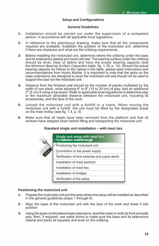
Standard single unit installation – with mast ties
Single unit setup with mast tiesSingle unit setup with mast tiesinstallation walkthroughPositioning the motorized unit
Connection to the power supply
Verifi cation of limit switches and panel alerts
Installation of mast sections
Installation of mast ties
Installation of bridges
Verifi cation of the setup
insnsnnnn tinsnnnnn tPos
ConCCCCCCCCCCCCCCCC
VerVVeVeVerVeVVVeVVeVVeVVV i
Positioning the motorized unit1- Prepare the motorized unit and the area where the setup will be installed as described in the general guidelines (steps 1 through 6).
2- Align the base of the motorized unit with the face of the work and lower it into position.
3- Using the jacks on the lateral base extensions, level the mast on both its front and side axis, then, if required, use metal shims to make sure the base and its extensions (lateral and back) sit squarely and level on the cribbing.

16
4- Select the appropriate power cable for the height of the setup. Refer to the Power Cable Selection Chart (fi g. 4.3, p. 40) for help with the selection of the power cable. Make sure that the overall length of the cable is suffi cient for the installation (height of setup, distance from power source, acceptable overall slack in cable). 5- Install and connect the power cable. This installation must be performed by a certifi ed electrician. For instructions on the installation of the power cable, refer to p. 41 of the Power Pack and Operating Components section. If an optional cable trolley kit is required for the installation, it will be installed when installing mast sections, in step 16.
Setup and Confi gurations
6- Using optional bridge installation support brackets or any other lifting device such as a crane or a forklift, install only one bridge on each side of the mast. Refer to the Bridges section on p. 23 for instructions on bridge installation. For more information about the use of bridge installation support brackets, refer to p. 66 of the Accessories section. Make sure the setup follows the guidelines for pre-installation. Refer to p. 52 of the Masts and Mast Ties section for more information about pre-installation. 7- Turn on the main disconnect switch, pull out the emergency stop button and unlock the display panel. Make sure that the inclinometer and communication options have been disabled in the control panel. Refer to the Power Pack and Operating Components section on p. 42 for instructions on how to turn on the main power. For information about the functions and alerts of the control panel, refer to the Control Panel section on p. 43. 8- Make sure that the control panel does not detect any event that would prevent the safe and appropriate operation of the unit. It is important to note that when the motorized unit is at base level, the control panel should display an alert for the bottom fi nal limit. Inspect the strobe under the main frame and make sure it is working appropriately. 9- Install one mast section. Refer to the Mast and Mast Ties section on p. 50 for instructions on the installation of mast sections. 10- With the motorized unit at base level and the power on, test the top fi nal limit switch by carefully raising the unit above the fi rst mast section. If the switch is working properly, the panel should display an alert and prevent upward travel. 11- Lower the motorized unit to test the bottom limit switch. If the switch is working properly, the panel should display an alert and prevent downward travel. Adjust or replace the bottom limit switch, if necessary. 12- Remove the aluminum cover located under the control panel. Test the bottom fi nal limit switch (the mechanical switch located on the main trolley, on the panel side) by lifting the arm of the bottom fi nal limit switch. If the switch is working properly, the bottom fi nal limit alert should be displayed on the panel. 13- Test the top limit switch by placing a metal object in front of it. The panel should display an alert for the top limit. Replace the aluminum cover. 14- If any of the limit switches is not working properly, call the service center or the Hydro Mobile technical support team. For more information about limit switches and their corresponding alerts, refer to the Control Panel section on p. 43. 15- Using an optional jib arm, a crane or a forklift, load mast sections on the platform (see p. 73 of the Accessories section for more information on the installation and use of the jib arm). Mast sections should be distributed equally on either side of the mast to ensure good balance. Refer to the Load Capacities section on p. 56 for more information about loading the platform.
Verifi cation of limit switches and panel alerts
Connection of the unit and control panel to the power supplyStandard single unit installation – with mast ties
1 - MOTORIZED UNIT
17
1 - MOTORIZED UNIT
16- Proceed with the installation of mast sections. Refer to p. 50 of the Mast and Mast Ties section for more details on how to install mast sections. If required by the setup, the optional cable trolley kit must be installed at this point. For instructions on the installation of the cable trolley and its components, refer to p. 75 of the Accessories section. 17- Continue installing mast sections until a mast tie is required, making sure throughout the process that the mast remains plumb on both its front and side axis. Install as many mast ties as required. Refer to p. 52 of the Masts and Mast Ties section for information on the number of mast ties required in a setup and instructions on their installation. 18- Install as many mast sections as required by the layout plan and allowed. Any S Series setup should not be raised over 500' (152 m), unless authorized in writing by Hydro Mobile prior to installation. Install the mast head on top of the last mast section. If a mast head is not used, make sure that the last mast section installed is a one-rack mast section and that it is installed backwards, with the rack facing toward the face of the work.19- Install the top limit trigger plate on the middle bar of the next to last mast section, on the same side as the control panel. To test the operation of the top limit switch, raise the unit until the switch reaches the trigger plate. The panel should display an alert for the top limit. Adjust the top limit switch, if required. If the limit switch is not working properly, call the service center or the Hydro Mobile technical support team. For more information about limit switches and their corresponding alerts, refer to the Control Panel section on p. 43. 20- Upon initial setup and subsequently after every eight hours of cumulative runtime (unit travel up and down the mast), grease must be applied to the rack(s) and gears, from the top of the setup down. For more information, refer to the daily inspection checklist recommended for this motorized unit. Grease must be allowed to stand for 2-3 hours before the motorized unit is used again. Use an open gear lubricant recommended by Hydro Mobile. Refer to p. 78 of the Transport, Storage and Maintenance section for more information on the appropriate lubrication method. Lower the motorized unit to base level, verifying the mast ties and the mast bolts and applying grease, as required, on the way down. Make sure that all bolt assemblies are properly secured and in good condition and that grease is applied appropriately. 21- Once the installation of masts and mast ties is complete, install all mast guards. Remove and store the jib arm, if necessary.Installation of bridges
Installation of mast sectionsStandard single unit installation – with mast ties
22- With the motorized unit at base level, complete the installation of bridges as required and allowed. Refer to the Load Capacities section on p. 56 for more information on the number of bridges allowed in a setup.
23- Make a fi nal verifi cation of the setup before authorizing workers to use the motorized unit. Make sure the access stairs and all the guardrails are in place and secure (see the Accessories section on p. 70 and p. 72 for more information about guardrails and access stairs). In all cases where workers are exposed to fall hazards greater than specifi ed by local regulations, the installation of guardrails or face guardrails is mandatory.24- Adjust the outriggers and install planks, as required (see p. 67 of the Accessories section for more information). 25- Before authorizing workers to use the motorized unit, perform every step in the daily inspection checklist. Refer to the Transport, Storage and Maintenance section on p. 77 for more information.
Verifi cation of the setup
Setup and Confi gurations
18
1 - MOTORIZED UNIT
Multiple unit installation – with mast ties
Setup and Confi gurations
(requires two twin mast adapters – sold separately)
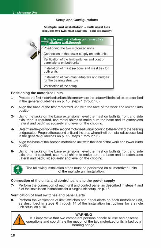
Multiple unit installation with mast tiesMultiple unit installation with mast tiesinstallation walkthroughPositioning the two motorized units
Connection to the power supply on both units
Verifi cation of the limit switches and control panel alerts on both units
Installation of mast sections and mast ties for both units
Installation of twin mast adapters and bridges for the bearing structure
Verifi cation of the setup
inssnsnnn tinssnsnnnn tPos
ConCoCCCCCCCCCCCCoC
VerVeVVeVeVeVerVVVVeVeVeeVe i
Positioning the motorized units1- Prepare the fi rst motorized unit and the area where the setup will be installed as described in the general guidelines on p. 15 (steps 1 through 6).
2- Align the base of the fi rst motorized unit with the face of the work and lower it into position.
3- Using the jacks on the base extensions, level the mast on both its front and side axis, then, if required, use metal shims to make sure the base and its extensions (lateral and back) sit squarely and level on the cribbing.
4- Determine the position of the second motorized unit according to the length of the bearing bridge setup. Prepare the second unit and the area where it will be installed as described in the general guidelines on p. 15 (steps 1 through 6).
5- Align the base of the second motorized unit with the face of the work and lower it into position.
6- Using the jacks on the base extensions, level the mast on both its front and side axis, then, if required, use metal shims to make sure the base and its extensions (lateral and back) sit squarely and level on the cribbing.
The following installation steps must be performed on all motorized units of the multiple unit installation.
7- Perform the connection of each unit and control panel as described in steps 4 and 5 of the installation instructions for a single unit setup, on p. 16.
Connection of the units and control panels to the power supply
Verifi cation of limit switches and panel alerts8- Perform the verifi cation of limit switches and panel alerts on each motorized unit, as described in steps 6 through 14 of the installation instructions for a single unit setup, on p. 16.
WARNINGIt is imperative that two competent persons handle all rise and descent
operations and coordinate the motion of the two motorized units linked by a bearing bridge.
19
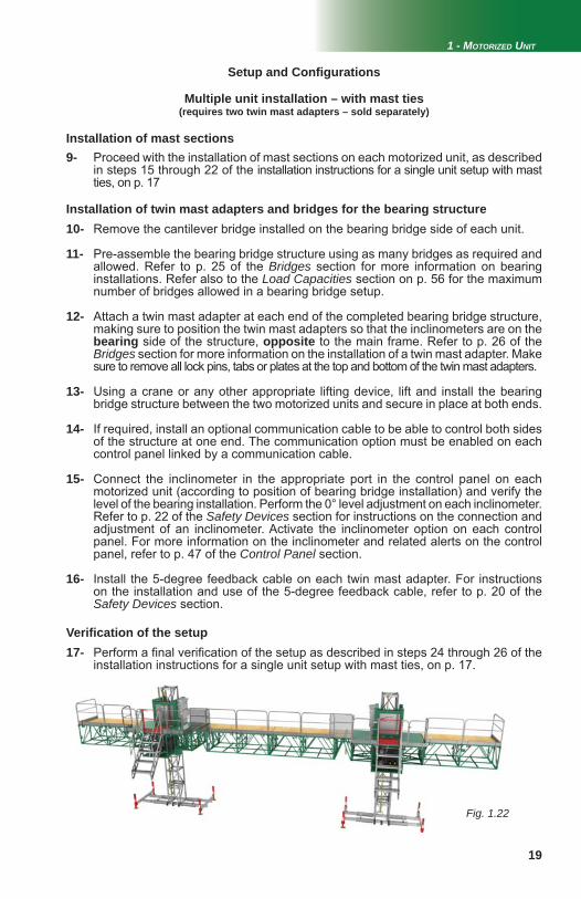
Fig. 1.22
1 - MOTORIZED UNIT
Setup and Confi gurations
Multiple unit installation – with mast ties(requires two twin mast adapters – sold separately)
9- Proceed with the installation of mast sections on each motorized unit, as described in steps 15 through 22 of the installation instructions for a single unit setup with mast ties, on p. 17
Installation of mast sections
Installation of twin mast adapters and bridges for the bearing structure10- Remove the cantilever bridge installed on the bearing bridge side of each unit.
11- Pre-assemble the bearing bridge structure using as many bridges as required and allowed. Refer to p. 25 of the Bridges section for more information on bearing installations. Refer also to the Load Capacities section on p. 56 for the maximum number of bridges allowed in a bearing bridge setup.
12- Attach a twin mast adapter at each end of the completed bearing bridge structure, making sure to position the twin mast adapters so that the inclinometers are on the
bearing side of the structure, opposite to the main frame. Refer to p. 26 of the Bridges section for more information on the installation of a twin mast adapter. Make
sure to remove all lock pins, tabs or plates at the top and bottom of the twin mast adapters.
13- Using a crane or any other appropriate lifting device, lift and install the bearing bridge structure between the two motorized units and secure in place at both ends.
14- If required, install an optional communication cable to be able to control both sides of the structure at one end. The communication option must be enabled on each control panel linked by a communication cable.
15- Connect the inclinometer in the appropriate port in the control panel on each motorized unit (according to position of bearing bridge installation) and verify the level of the bearing installation. Perform the 0° level adjustment on each inclinometer. Refer to p. 22 of the Safety Devices section for instructions on the connection and adjustment of an inclinometer. Activate the inclinometer option on each control panel. For more information on the inclinometer and related alerts on the control panel, refer to p. 47 of the Control Panel section.
16- Install the 5-degree feedback cable on each twin mast adapter. For instructions on the installation and use of the 5-degree feedback cable, refer to p. 20 of the Safety Devices section.
Verifi cation of the setup17- Perform a fi nal verifi cation of the setup as described in steps 24 through 26 of the installation instructions for a single unit setup with mast ties, on p. 17.
20
Fig. 2.3 Fig. 2.4 Fig. 2.5
Fig. 2.6Fig. 2.7
Fig. 2.1 Fig. 2.2
2 - SAFETY DEVICES
Emergency Descent Control System
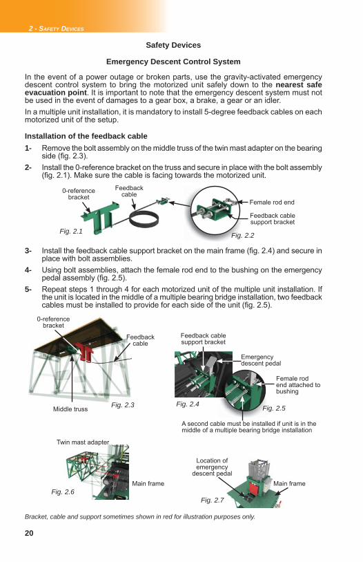
In the event of a power outage or broken parts, use the gravity-activated emergency descent control system to bring the motorized unit safely down to the nearest safe evacuation point. It is important to note that the emergency descent system must not be used in the event of damages to a gear box, a brake, a gear or an idler. In a multiple unit installation, it is mandatory to install 5-degree feedback cables on each motorized unit of the setup.
Safety Devices
Installation of the feedback cable1- Remove the bolt assembly on the middle truss of the twin mast adapter on the bearing side (fi g. 2.3). 2- Install the 0-reference bracket on the truss and secure in place with the bolt assembly (fi g. 2.1). Make sure the cable is facing towards the motorized unit.
0-reference bracket
Feedback cable
Middle truss
Feedback cable support bracket
Female rod end attached to bushing
Emergency descent pedal
Main frame
Bracket, cable and support sometimes shown in red for illustration purposes only.
Twin mast adapter
A second cable must be installed if unit is in the middle of a multiple bearing bridge installation
Location of emergency
descent pedalMain frame
0-reference bracket
Feedback cable
Female rod end
Feedback cable support bracket
3- Install the feedback cable support bracket on the main frame (fi g. 2.4) and secure in place with bolt assemblies. 4- Using bolt assemblies, attach the female rod end to the bushing on the emergency pedal assembly (fi g. 2.5). 5- Repeat steps 1 through 4 for each motorized unit of the multiple unit installation. If the unit is located in the middle of a multiple bearing bridge installation, two feedback cables must be installed to provide for each side of the unit (fi g. 2.5).
21
2 - SAFETY DEVICES
Emergency descent procedure for a multiple unit installation
Emergency Descent Control System
The Hydro Mobile S Series is equipped with centrifugal brakes. This safety feature is designed to automatically bring the motorized unit and the installation safely down to nearest safe evacuation point at a factory-set speed. It is important to make sure that the brakes are allowed to cool down for 5 minutes after every 30' (9,1 m) of descent.
Centrifugal brakes
Safety Devices
1- Turn off the main disconnect switch to shut down the power on each motorized unit of the multiple unit installation. It may be required by local regulations for the operator to be tied to the unit using one of the D-rings on the main frame during the emergency descent.
2- Make sure the 5-degree feedback cable kit is properly installed on each motorized unit of the multiple unit installation. It is important to note that since the inclinometers do not work during the emergency descent of a multiple unit structure, any slope of the structure exceeding ±5 degrees will be detected by the feedback cable. In the event of a slope of the structure exceeding ±5 degrees, the feedback cable will prevent the use of the emergency descent pedal on the motorized unit at the lowest position until the structure is level again.
3- Remove the toggle pin to unlock each emergency descent pedal. Simultaneously, on each motorized unit of the multiple unit installation, step on and hold the emergency descent pedal fully depressed (fi g. 2.4 and fi g. 2.7) to initiate the emergency descent. The platform will descend at a pre-determined speed.
4- Allow the installation to lower 30' (9,1 m) then release each pedal and let the centrifugal brakes cool down for 5 minutes before resuming descent. Proceed in that fashion down to the nearest safe evacuation point.5- It is important to note that the bottom limit sensors and audible alarms do not work during a manual descent of the platform. Make sure that all workers on and off the platform have been warned and that the areas below and around the descending setup have been cleared and remain free of obstacles and workers. It is recommended to monitor carefully the lowering of the platform during the emergency descent.
1- Turn off the main disconnect switch to shut down the power (fi g. 6.1, p. 43). It may be required by local regulations for the operator to be tied to the unit using one of the D-rings on the main frame during the emergency descent.
2- Open the access panel on the main frame. Remove the toggle pin to unlock the emergency descent pedal. Step on and hold the emergency descent pedal fully depressed (fi g. 2.4 and fi g. 2.7) to initiate the emergency descent. The platform will descend at a pre-determined speed.
3- Allow the installation to lower 30' (9,1 m) then release the pedal and let the centrifugal brakes cool down for 5 minutes before resuming descent. Proceed in that fashion down to the nearest safe evacuation point.4- It is important to note that the bottom limit sensor and audible alarm do not work during a manual descent of the platform. Make sure that all workers on and off the platform have been warned and that the areas below and around the descending setup have been cleared and remain free of obstacles and workers. It is recommended to monitor carefully the lowering of the platform during the emergency descent.
Emergency descent procedure for a single unit installation

22
Fig. 2.8
2 - SAFETY DEVICES
Inclinometer
Safety Devices
1- Make sure the twin mast adapter is properly bolted to the main frame. Refer to p. 26 of the Bridges section for more information on the installation and use of a twin mast adapter.
2- Connect one end of the inclinometer extension cable to the inclinometer.
3- Run the inclinometer extension cable through the bottom part of the main frame. Connect the extension cable in the proper inclinometer port under the control panel. If the bearing bridge is to the left of the unit, the cable must be connected in the
LEFT inclinometer port. If the bearing bridge is located to the right of the unit, the cable must be connected in the RIGHT inclinometer port.
4- Activate the appropriate inclinometer (LEFT or RIGHT, as determined in step 3) on the control panel and perform the adjustment of the 0-degree level position, as described in the instructions below.
5- Repeat steps 1 through 4 for the other inclinometer (LEFT or RIGHT, as determined in step 3).
Used only in bearing confi gurations, the inclinometer is located on the twin mast adapter and must absolutely be connected to the control panel. The inclinometer will detect any ± 2-degree slope of the structure and the control panel will display an alert message to warn the operator. For more information on the installation and use of a twin mast adapter, see p. 26 of the Bridges section. For more information about alert messages, see the Control Panel section on p. 43.
Connection
1- When the motorized unit is moving, if the inclinometer detects a slope of ± 2 degrees, a signal is automatically sent to the control panel and a ± 2-degree alert message is displayed.
2- If the structure is rising, the motorized unit that is at the highest level (-2 deg.) will automatically stop while the lowest side (2 deg.) will continue to rise until the structure is brought back to level.
3- If the structure is descending, the motorized unit that is at the lowest level (2 deg.) in the confi guration will automatically stop while the highest side (-2 deg.) will continue to descend until the structure is brought back to level.
Detection of a ± 2-degree slope
1- Make sure the bearing bridge structure is level.2- Activate the panel display screen and select the inputs/outputs section (F3) on the main menu screen. 3- Navigate to the page where the inclinometer level readings are displayed (fi g. 2.8). 4- Loosen the adjustment bolt on the LEFT inclinometer sensor (as determined in step 3 of the connection steps above).
Adjustment of the 0° level position
5- Move the sensor until a 0.00 reading for the LEFT inclinometer is displayed on the screen. Tighten the bolt to secure the sensor in place. 6- Repeat steps 2 through 5 to adjust the inclinometer sensor at the other end (RIGHT, as determined in step 3 of the connection steps above).
23
Fig. 3.1
Fig. 3.3
Fig. 3.4 Fig. 3.5
3 - BRIDGES
Standard bridge
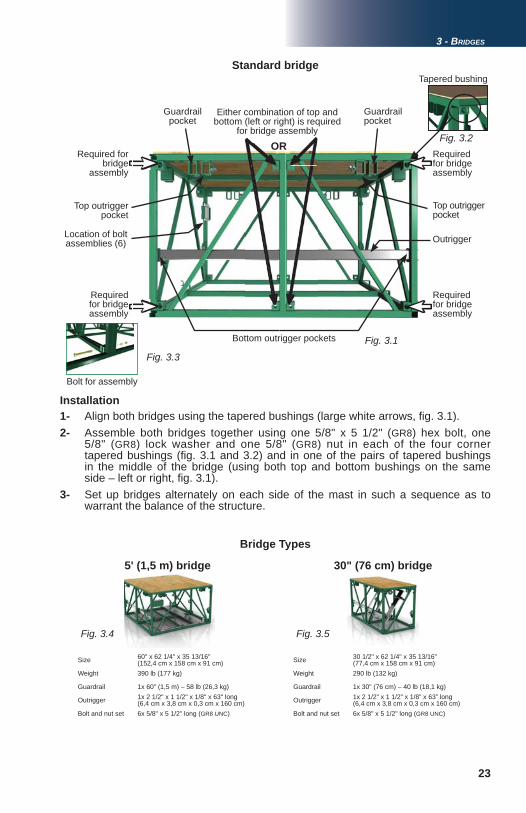
1- Align both bridges using the tapered bushings (large white arrows, fi g. 3.1). 2- Assemble both bridges together using one 5/8" x 5 1/2" (GR8) hex bolt, one 5/8" (GR8) lock washer and one 5/8" (GR8) nut in each of the four corner tapered bushings (fi g. 3.1 and 3.2) and in one of the pairs of tapered bushings in the middle of the bridge (using both top and bottom bushings on the same side – left or right, fi g. 3.1). 3- Set up bridges alternately on each side of the mast in such a sequence as to warrant the balance of the structure.
Installation
Fig. 3.2
Guardrail pocket
Tapered bushing
Either combination of top and bottom (left or right) is required
for bridge assembly
Top outrigger pocket
Bolt for assembly
Bottom outrigger pockets
Guardrail pocket
Top outrigger pocket
Required for bridge
assembly
Required for bridge assembly
Required for bridge assembly
Required for bridge assembly
Location of bolt assemblies (6) Outrigger
OR
Size 60" x 62 1/4" x 35 13/16"(152,4 cm x 158 cm x 91 cm)
Weight 390 lb (177 kg)
Guardrail 1x 60" (1,5 m) – 58 lb (26,3 kg)
Outrigger 1x 2 1/2" x 1 1/2" x 1/8" x 63" long (6,4 cm x 3,8 cm x 0,3 cm x 160 cm)
Bolt and nut set 6x 5/8" x 5 1/2" long (GR8 UNC)
Size 30 1/2" x 62 1/4" x 35 13/16"(77,4 cm x 158 cm x 91 cm)
Weight 290 lb (132 kg)
Guardrail 1x 30" (76 cm) – 40 lb (18,1 kg)
Outrigger 1x 2 1/2” x 1 1/2” x 1/8” x 63” long (6,4 cm x 3,8 cm x 0,3 cm x 160 cm)
Bolt and nut set 6x 5/8" x 5 1/2" long (GR8 UNC)
Bridge Types
5' (1,5 m) bridge 30" (76 cm) bridge
24
Fig. 3.7Fig. 3.6
Fig. 3.8
3 - BRIDGES
Cantilever Bridge
Installation
Bridges
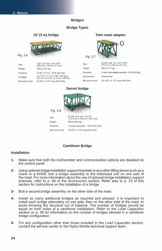
10' (3 m) bridge
1- Make sure that both the inclinometer and communication options are disabled on the control panel.
2- Using optional bridge installation support brackets or any other lifting device such as a crane or a forklift, bolt a bridge assembly to the motorized unit on one side of the mast. For more information about the use of optional bridge installation support brackets, refer to p. 66 of the Accessories section. Refer also to p. 23 of this section for instructions on the installation of a bridge.
3- Bolt a second bridge assembly on the other side of the mast.
4- Install as many additional bridges as required and allowed. It is important to install each bridge alternately on one side, then on the other side of the mast, to avoid throwing the structure out of balance. The number of bridges should be equal on both sides of a cantilever installation. Refer to the Load Capacities section on p. 56 for information on the number of bridges allowed in a cantilever bridge confi guration.
5- For any confi guration other than those included in the Load Capacities section, contact the service center or the Hydro Mobile technical support team.
Size 30 3/8" x 62 1/4" x 35 13/16"(77,2 cm x 158 cm x 91 cm)
Weight 390 lb (177 kg)
Guardrail 1x twin mast adapter guardrail – 45 lb (20,4 kg)
Accessories Inclinometer
Bolt and nut set 12x 5/8" x 5 1/2" long (GR8 UNC)
Twin mast adapter
Bridge Types
Size 67 7/8" x 62 1/4" x 39 1/2"(172,4 cm x 158 cm x 100,3 cm)
Weight 800 lb (363 kg)
Guardrail 1x swivel guardrail – 120 lb (54,4 kg)
Bolt and nut set 6x 5/8" x 5 1/2" long (GR8 UNC)
Swivel bridge
Size 120" x 62 1/4" x 35 13/16"(305 cm x 158 cm x 91 cm)
Weight 720 lb (327 kg)
Guardrail 2x 60" (1,5 m) – 58 lb (26,3 kg)
Outrigger 2x 2 1/2" x 1 1/2" x 1/8" x 63" long (6,4 cm x 3,8 cm x 0,3 cm x 160 cm)
Bolt and nut set 6x 5/8" x 5 1/2" long (GR8 UNC)
25
3 - BRIDGES
Bearing Bridge
1- Align and bolt together the fi rst two bridges of the bearing structure as described in steps 1 and 2 of the standard bridge installation instructions, p. 23.2- Repeat step 1 until the bearing structure has the desired length. Refer to the Load Capacities section on p. 56 for the maximum number of bridges allowed in a bearing bridge confi guration.3- Attach a twin mast adapter at each end of the bearing structure. Refer to p. 26 of this section for information on the installation and use of a twin mast adapter. 4- Using a rough terrain forklift, a crane or any other lifting device, lift the bearing structure and lower it into position, between the two motorized units. 5- Bolt each twin mast adapter to the main frame of the motorized unit. Make sure to unlock the locking pins, tabs or plates on each twin mast adapter, 6- Plug in each inclinometer and enable the inclinometer option on each control panel of the bearing bridge installation. Perform the 0-degree level adjustment on each inclinometer. Refer to p. 22 of the Safety Devices section for more information on the installation and use of inclinometers, and on the 0-degree level adjustment procedure. Refer to p. 49 of the Control Panel section for more information about enabling the inclinometer option.7- Connect each feedback cable required. Refer to p. 20 of the Safety Devices section for more information on the installation and use of feedback cables.
8- Install optional communication cables, if required. Enable the communication option on the control panel of each of the units linked together by a communication cable. Refer to p. 49 of the Control Panel section for more information about enabling the communication option.
Installation
Safety guidelines1- To ensure safe and proper operation, it is suggested that two persons be on hand to perform maneuvers for each motorized unit in a setup. The motion of motorized units linked by a bearing bridge must be coordinated and supervised by a competent person on each motorized unit to ensure that the structure slope does not exceed 2 degrees.2- Daily verifi cation and testing of all the inclinometers are recommended before operating the motorized units.
Bridges
(requires the use of two motorized units and two twin mast adapters)
1- To dismantle a bearing bridge structure, lower both motorized units until the platform is at base level.2- Completely unload the working platform and make workers step off the structure.3- Disconnect the inclinometers, communication cables and feedback cables at both ends of the bearing structure and disable the inclinometer and communication options on each control panel. 4- Replace the locking pins, tabs or plates on each twin mast adapters. 5- Unbolt the twin mast adapters from the main frames of the motorized units. 6- Using a forklift, a crane or any other lifting device, slightly raise the bearing bridge and lower it on the ground to dismantle it.
Dismantling a bearing bridge structure
26
Fig. 3.10
Fig. 3.9
3 - BRIDGES
Twin Mast Adapter
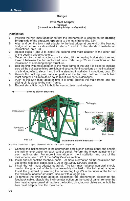
1- Position the twin mast adapter so that the inclinometer is located on the bearing bridge side of the structure, opposite to the main frame (fi g. 3.9). 2- Align and bolt the twin mast adapter to the last bridge at one end of the bearing bridge structure, as described in steps 1 and 2 of the standard installation instructions, on p. 23.3- Repeat steps 1 and 2 to install the second twin mast adapter at the other end of the bearing bridge structure. 4- Once both twin mast adapters are installed, lift the bearing bridge structure and lower it between the two motorized units. Refer to p. 25 for instructions on the installation of a bearing bridge structure. 5- Bolt the fi rst twin mast adapter to the main frame of the unit it is close to, making sure all the bolt assemblies are tight and secure. For instructions on the installation of a bridge, refer to steps 1 and 2 of the standard installation instructions, on p. 23. 6- Unlock the locking pins, tabs or plates at the top and bottom of each twin mast adapter. Failure to do so could result into serious damages.7- Push in the twin mast adapter until it is snug against the main frame and the sliding pin is close to the main frame. 8- Repeat steps 5 through 7 to bolt the second twin mast adapter.
Installation
9- Connect the inclinometers in the appropriate port in each control panel and enable the inclinometer option on each control panel. Perform the 0-level adjustment of each inclinometer. For more information on the installation and use of the inclinometer, see p. 22 of the Safety Devices section.10- Install and connect the feedback cable. For more information on the installation and use of the feedback cable, see p. 20 of the Safety Devices section. 11- Install the twin mast adapter guardrail. The twin mast adapter guardrail should overlap the guardrail of the bridge assembly attached to the twin mast adapter. Install the guardrail by inserting the connecting lugs (2) in the tubes at the top of the twin mast adapter structure. Secure with a toggle pin.12- To remove the twin mast adapter, disconnect the inclinometer, disconnect the feedback cable, disable the inclinometer option on the control panel, remove the twin mast adapter guardrail, replace the locking pins, tabs or plates and unbolt the twin mast adapter from the main frame.
Bearing side of structure
(optional)(required for a bearing bridge confi guration)
Bridges
Main frame side of structure
Inclinometer
Feedback cable
Bracket, cable and support shown in red for illustration purposes.
Sliding pin
Main frame
Twin mast adapter
27
Fig. 3.12
Fig. 3.14
Fig. 3.11
Fig. 3.16
Fig. 3.13
Fig. 3.15
3 - BRIDGES
Forward/Back Extension Bridge(optional)
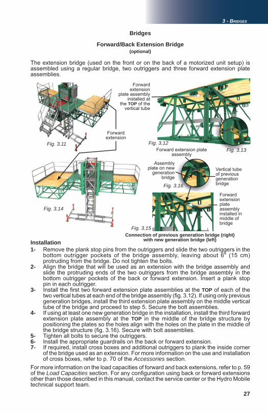
The extension bridge (used on the front or on the back of a motorized unit setup) is assembled using a regular bridge, two outriggers and three forward extension plate assemblies.
1- Remove the plank stop pins from the outriggers and slide the two outriggers in the bottom outrigger pockets of the bridge assembly, leaving about 6" (15 cm) protruding from the bridge. Do not tighten the bolts. 2- Align the bridge that will be used as an extension with the bridge assembly and slide the protruding ends of the two outriggers from the bridge assembly in the bottom outrigger pockets of the back or forward extension. Insert a plank stop pin in each outrigger.3- Install the fi rst two forward extension plate assemblies at the TOP of each of the two vertical tubes at each end of the bridge assembly (fi g. 3.12). If using only previous generation bridges, install the third extension plate assembly on the middle vertical tube of the bridge and proceed to step 5. Secure the bolt assemblies.4- If using at least one new generation bridge in the installation, install the third forward extension plate assembly at the TOP in the middle of the bridge structure by positioning the plates so the holes align with the holes on the plate in the middle of the bridge structure (fi g. 3.16). Secure with bolt assemblies.5- Tighten all bolts to secure the outriggers. 6- Install the appropriate guardrails on the back or forward extension.7- If required, install cross boxes and additional outriggers to plank the inside corner of the bridge used as an extension. For more information on the use and installation of cross boxes, refer to p. 70 of the Accessories section.For more information on the load capacities of forward and back extensions, refer to p. 59 of the Load Capacities section. For any confi guration using back or forward extensions other than those described in this manual, contact the service center or the Hydro Mobile technical support team.
Forward extension
Forward extension
plate assembly installed at
the TOP of the vertical tube
Installation
Bridges
Forward extension plate assembly installed in middle of bridge
Connection of previous generation bridge (right) with new generation bridge (left)
Vertical tube of previous generation bridge
Assembly plate on new
generation bridge
Forward extension plate assembly
28
Fig. 3.17
3 - BRIDGES
Bridges
Bridge Deck Extension(optional)
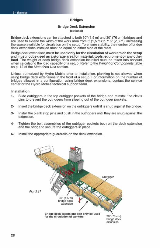
Bridge deck extensions can be attached to both 60" (1,5 m) and 30" (76 cm) bridges and are used to extend the width of the work area from 5' (1,5 m) to 7' 6" (2,3 m), increasing the space available for circulation on the setup. To ensure stability, the number of bridge deck extensions installed must be equal on either side of the mast. Bridge deck extensions must be used only for the circulation of workers on the setupand must not be used as a storage area for material, tools, equipment or any other load. The weight of each bridge deck extension installed must be taken into account when calculating the load capacity of a setup. Refer to the Weight of Components table on p. 12 of the Motorized Unit section.
Unless authorized by Hydro Mobile prior to installation, planking is not allowed when using bridge deck extensions in the front of a setup. For information on the number of bridges allowed in a confi guration using bridge deck extensions, contact the service center or the Hydro Mobile technical support team.
Installation1- Slide outriggers in the top outrigger pockets of the bridge and reinstall the clevis pins to prevent the outriggers from slipping out of the outrigger pockets.
2- Insert the bridge deck extension on the outriggers until it is snug against the bridge.
3- Install the plank stop pins and push in the outriggers until they are snug against the extension.
4- Tighten the bolt assemblies of the outrigger pockets both on the deck extension and the bridge to secure the outriggers in place.
6- Install the appropriate guardrails on the deck extension.
30" (76 cm) bridge deck extension
Outrigger
60" (1,5 m) bridge deck
extension
Bridge deck extensions can only be used for the circulation of workers.
29
Cut
-out
A0800001-0004
Corner / Coin / Esquina
45o 45 o
90 o
180o
Corner / Coin / Esquina
90o
For any setup in thered zone,
please call your local distributor
Pour toute installation dans la zone rouge,
veuillez contacter votre distributeur local
Es necesario que llame a su distribuidor para
cualquier montaje en la zona roja
For any setup in thered zone,
please call your local distributor
Pour toute installation dans la zone rouge,
veuillez contacter votre distributeur local
Es necesario que llame a su distribuidor para
cualquier montaje en la zona roja
Fig. 3.18
Fig. 3.19
Fig. 3.20Fig. 3.20
3 - BRIDGES
Swivel Bridge(optional)
Bridges
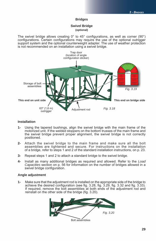
The swivel bridge allows creating 0° to 45° confi gurations, as well as corner (90°) confi gurations. Certain confi gurations may require the use of the optional outrigger support system and the optional counterweight adapter. The use of weather protection is not recommended on an installation using a swivel bridge.
Installation
This end on unit side
Storage of bolt assemblies
This end on bridge side
63" (1,6 m) outrigger Adjustment rod
Trap door (location of angle
confi guration sticker)
1- Using the tapered bushings, align the swivel bridge with the main frame of the motorized unit. If the welded stoppers on the bottom trusses of the main frame and the swivel bridge prevent proper alignment, the swivel bridge is not correctly positioned.
2- Attach the swivel bridge to the main frame and make sure all the bolt assemblies are tightened and secure. For instructions on the installation of a bridge, refer to steps 1 and 2 of the standard installation instructions, on p. 23.
3- Repeat steps 1 and 2 to attach a standard bridge to the swivel bridge.
4- Install as many additional bridges as required and allowed. Refer to the Load Capacities section on p. 56 for information on the number of bridges allowed in a swivel bridge confi guration.
Angle adjustment
1- Make sure that the adjustment rod is installed on the appropriate side of the bridge to achieve the desired confi guration (see fi g. 3.28, fi g. 3.29, fi g. 3.32 and fi g. 3.33). If required, remove the bolt assemblies at both ends of the adjustment rod and reinstall on the other side of the bridge (fi g. 3.20).
Bolt assemblies
30
Fig. 3.21
Fig. 3.22
Fig. 3.24
Fig. 3.26
Fig. 3.25
Fig. 3.27
Fig. 3.23
3 - BRIDGES
Bridges
Swivel Bridge Guardrails
Swivel Bridge
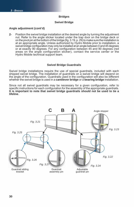
Swivel bridge installations require the use of special guardrails, included with each shipped swivel bridge. The installation of guardrails on a swivel bridge will depend on the angle of the confi guration. Guardrails used in the confi guration will also be different whether the swivel bridge is used in a cantilever bridge or a bearing bridge installation.
Since not all swivel guardrails may be necessary for a given confi guration, refer to specifi c instructions for each confi guration for the assembly of the appropriate guardrails. It is important to note that swivel bridge guardrails should not be used to tie a lifeline.
2- Position the swivel bridge installation at the desired angle by turning the adjustment nut. Refer to the angle sticker located under the trap door on the bridge deck or on the pivot pin at the bottom of the bridge (fi g. 3.19, p. 29) to make sure the installation is at an appropriate angle. Unless authorized by Hydro Mobile prior to installation, a swivel bridge confi guration may only be installed at an angle between 0 and 45 degrees or at exactly 90 degrees. For any confi guration between 45 and 90 degrees (red areas on the angle configuration sticker), contact the service center or the Hydro Mobile technical support team.
Angle adjustment (cont’d)
C B A
Guardrail sliding bracket
Angle stopper
Guardrail assembly pin
Adjustable guardrail pin
31
0°
45°
90°
Fig. 3.28 Fig. 3.29
Fig. 3.30 Fig. 3.31
Standard guardrail
3 - BRIDGES
Bridges
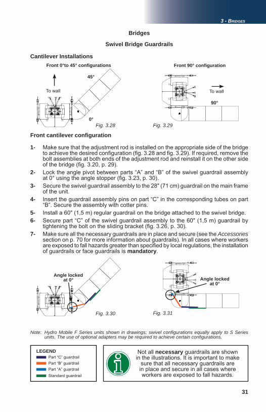
1- Make sure that the adjustment rod is installed on the appropriate side of the bridge to achieve the desired confi guration (fi g. 3.28 and fi g. 3.29). If required, remove the bolt assemblies at both ends of the adjustment rod and reinstall it on the other side of the bridge (fi g. 3.20, p. 29). 2- Lock the angle pivot between parts “A” and “B” of the swivel guardrail assembly at 0° using the angle stopper (fi g. 3.23, p. 30). 3- Secure the swivel guardrail assembly to the 28" (71 cm) guardrail on the main frame of the unit. 4- Insert the guardrail assembly pins on part “C” in the corresponding tubes on part “B”. Secure the assembly with cotter pins. 5- Install a 60" (1,5 m) regular guardrail on the bridge attached to the swivel bridge.6- Secure part “C” of the swivel guardrail assembly to the 60" (1,5 m) guardrail by tightening the bolt on the sliding bracket (fi g. 3.26, p. 30).7- Make sure all the necessary guardrails are in place and secure (see the Accessories
section on p. 70 for more information about guardrails). In all cases where workers are exposed to fall hazards greater than specifi ed by local regulations, the installation of guardrails or face guardrails is mandatory.
Cantilever InstallationsFront 0°to 45° confi gurations
To wall
Front 90° confi guration
Front cantilever confi guration
LEGENDPart “C” guardrailPart “B” guardrailPart “A” guardrail
Angle locked at 0°
Angle locked at 0°
Not all necessary guardrails are shown in the illustrations. It is important to make
sure that all necessary guardrails are in place and secure in all cases where workers are exposed to fall hazards.
To wall
Swivel Bridge Guardrails
Note: Hydro Mobile F Series units shown in drawings; swivel confi gurations equally apply to S Series units. The use of optional adapters may be required to achieve certain confi gurations.
32
0°
45°
90°
Fig. 3.32 Fig. 3.33
Fig. 3.34 Fig. 3.35
3 - BRIDGES
Bridges
To wall
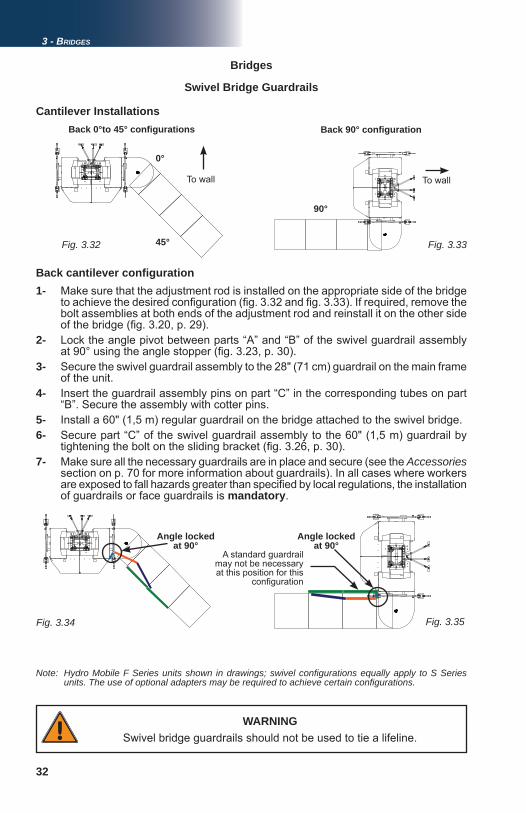
Back 0°to 45° confi gurations Back 90° confi guration
1- Make sure that the adjustment rod is installed on the appropriate side of the bridge to achieve the desired confi guration (fi g. 3.32 and fi g. 3.33). If required, remove the bolt assemblies at both ends of the adjustment rod and reinstall it on the other side of the bridge (fi g. 3.20, p. 29). 2- Lock the angle pivot between parts “A” and “B” of the swivel guardrail assembly at 90° using the angle stopper (fi g. 3.23, p. 30). 3- Secure the swivel guardrail assembly to the 28" (71 cm) guardrail on the main frame of the unit. 4- Insert the guardrail assembly pins on part “C” in the corresponding tubes on part “B”. Secure the assembly with cotter pins. 5- Install a 60" (1,5 m) regular guardrail on the bridge attached to the swivel bridge.6- Secure part “C” of the swivel guardrail assembly to the 60" (1,5 m) guardrail by tightening the bolt on the sliding bracket (fi g. 3.26, p. 30).7- Make sure all the necessary guardrails are in place and secure (see the Accessories section on p. 70 for more information about guardrails). In all cases where workers are exposed to fall hazards greater than specifi ed by local regulations, the installation of guardrails or face guardrails is mandatory.
Back cantilever confi guration
Cantilever Installations
Angle locked at 90°
Angle locked at 90°
A standard guardrail may not be necessary at this position for this
confi guration
To wall
WARNINGSwivel bridge guardrails should not be used to tie a lifeline.
Swivel Bridge Guardrails
Note: Hydro Mobile F Series units shown in drawings; swivel confi gurations equally apply to S Series units. The use of optional adapters may be required to achieve certain confi gurations.
33
Fig. 3.36
Bridges
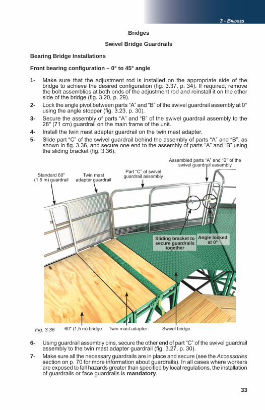
Bearing Bridge Installations
1- Make sure that the adjustment rod is installed on the appropriate side of the bridge to achieve the desired confi guration (fi g. 3.37, p. 34). If required, remove the bolt assemblies at both ends of the adjustment rod and reinstall it on the other side of the bridge (fi g. 3.20, p. 29). 2- Lock the angle pivot between parts “A” and “B” of the swivel guardrail assembly at 0° using the angle stopper (fi g. 3.23, p. 30). 3- Secure the assembly of parts “A” and “B” of the swivel guardrail assembly to the 28" (71 cm) guardrail on the main frame of the unit.4- Install the twin mast adapter guardrail on the twin mast adapter. 5- Slide part “C” of the swivel guardrail behind the assembly of parts “A” and “B”, as shown in fi g. 3.36, and secure one end to the assembly of parts “A” and “B” using the sliding bracket (fi g. 3.36).
Front bearing confi guration – 0° to 45° angle
Swivel bridge
Standard 60" (1,5 m) guardrail
Twin mast adapter guardrail
Part “C” of swivel guardrail assembly
Assembled parts “A” and “B” of the swivel guardrail assembly
Twin mast adapter60" (1,5 m) bridge
6- Using guardrail assembly pins, secure the other end of part “C” of the swivel guardrail assembly to the twin mast adapter guardrail (fi g. 3.27, p. 30).7- Make sure all the necessary guardrails are in place and secure (see the Accessories
section on p. 70 for more information about guardrails). In all cases where workers are exposed to fall hazards greater than specifi ed by local regulations, the installation of guardrails or face guardrails is mandatory.
Swivel Bridge Guardrails
Sliding bracket to secure guardrails
together
Angle locked at 0°
3 - BRIDGES
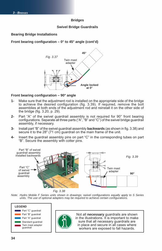
34
45°Fig. 3.37
Fig. 3.38
90°
Fig. 3.39
Bridges
LEGENDPart “C” guardrailPart “B” guardrailPart “A” guardrail
Angle locked at 0°
Not all necessary guardrails are shown in the illustrations. It is important to make
sure that all necessary guardrails are in place and secure in all cases where workers are exposed to fall hazards.
Standard guardrailTwin mast adapter guardrail
Bearing Bridge Installations
Front bearing confi guration – 0° to 45° angle (cont’d)
1- Make sure that the adjustment rod is installed on the appropriate side of the bridge to achieve the desired confi guration (fi g. 3.39). If required, remove the bolt assemblies at both ends of the adjustment rod and reinstall it on the other side of the bridge (fi g. 3.20, p. 29). 2- Part “A” of the swivel guardrail assembly is not required for 90° front bearing confi gurations. Separate all three parts (“A”, “B” and “C”) of the swivel bridge guardrail assembly, if necessary.3- Install part “B” of the swivel guardrail assembly backwards (as shown in fi g. 3.38) and secure it to the 28" (71 cm) guardrail on the main frame of the unit. 4- Insert the guardrail assembly pins on part “C” in the corresponding tubes on part “B”. Secure the assembly with cotter pins.
Front bearing confi guration – 90° angle
Twin mast adapter
Part “C” of swivel guardrail
assembly
Part “B” of swivel guardrail assembly
installed backwards
Twin mast adapter
Swivel Bridge Guardrails
3 - BRIDGES
Note: Hydro Mobile F Series units shown in drawings; swivel confi gurations equally apply to S Series units. The use of optional adapters may be required to achieve certain confi gurations.
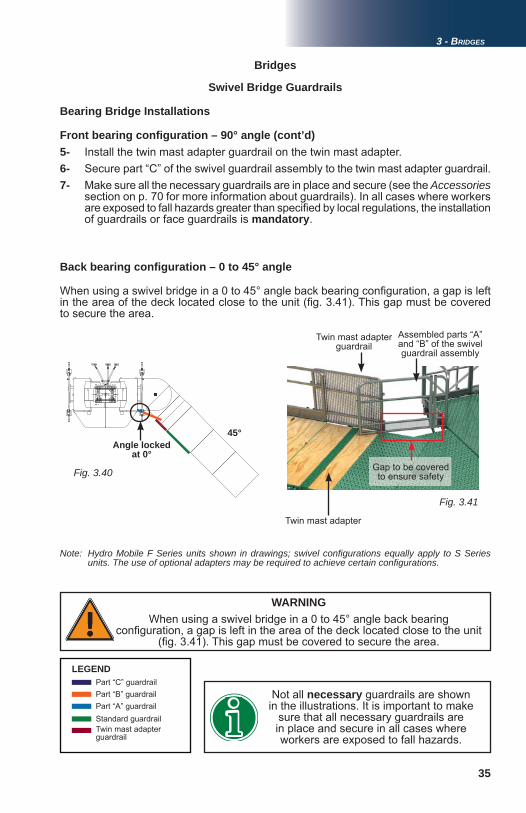
35
Fig. 3.40
45°
Fig. 3.41
3 - BRIDGES
Bridges
Bearing Bridge Installations
Front bearing confi guration – 90° angle (cont’d)5- Install the twin mast adapter guardrail on the twin mast adapter.6- Secure part “C” of the swivel guardrail assembly to the twin mast adapter guardrail.7- Make sure all the necessary guardrails are in place and secure (see the Accessories
section on p. 70 for more information about guardrails). In all cases where workers are exposed to fall hazards greater than specifi ed by local regulations, the installation of guardrails or face guardrails is mandatory.
Back bearing confi guration – 0 to 45° angle
LEGENDPart “C” guardrail
Part “A” guardrailNot all necessary guardrails are shown in the illustrations. It is important to make
sure that all necessary guardrails are in place and secure in all cases where workers are exposed to fall hazards.
Standard guardrailTwin mast adapter guardrail
Part “B” guardrail
When using a swivel bridge in a 0 to 45° angle back bearing confi guration, a gap is left in the area of the deck located close to the unit (fi g. 3.41). This gap must be covered to secure the area.
WARNINGWhen using a swivel bridge in a 0 to 45° angle back bearing
confi guration, a gap is left in the area of the deck located close to the unit (fi g. 3.41). This gap must be covered to secure the area.
Angle locked at 0°
Swivel Bridge Guardrails
Twin mast adapter guardrail
Assembled parts “A” and “B” of the swivel guardrail assembly
Gap to be covered to ensure safety
Twin mast adapter
Note: Hydro Mobile F Series units shown in drawings; swivel confi gurations equally apply to S Series units. The use of optional adapters may be required to achieve certain confi gurations.
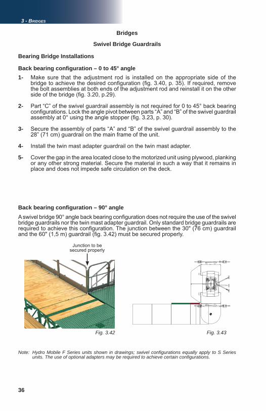
36
Fig. 3.43Fig. 3.42
Bridges
Bearing Bridge Installations
1- Make sure that the adjustment rod is installed on the appropriate side of the bridge to achieve the desired confi guration (fi g. 3.40, p. 35). If required, remove the bolt assemblies at both ends of the adjustment rod and reinstall it on the other side of the bridge (fi g. 3.20, p.29).
2- Part “C” of the swivel guardrail assembly is not required for 0 to 45° back bearing confi gurations. Lock the angle pivot between parts “A” and “B” of the swivel guardrail assembly at 0° using the angle stopper (fi g. 3.23, p. 30).
3- Secure the assembly of parts “A” and “B” of the swivel guardrail assembly to the 28” (71 cm) guardrail on the main frame of the unit.
4- Install the twin mast adapter guardrail on the twin mast adapter.
5- Cover the gap in the area located close to the motorized unit using plywood, planking or any other strong material. Secure the material in such a way that it remains in place and does not impede safe circulation on the deck.
Back bearing confi guration – 0 to 45° angle
Back bearing confi guration – 90° angleA swivel bridge 90° angle back bearing confi guration does not require the use of the swivel bridge guardrails nor the twin mast adapter guardrail. Only standard bridge guardrails are required to achieve this confi guration. The junction between the 30" (76 cm) guardrail and the 60" (1,5 m) guardrail (fi g. 3.42) must be secured properly.
Swivel Bridge Guardrails
3 - BRIDGES
Note: Hydro Mobile F Series units shown in drawings; swivel confi gurations equally apply to S Series units. The use of optional adapters may be required to achieve certain confi gurations.
Junction to be secured properly
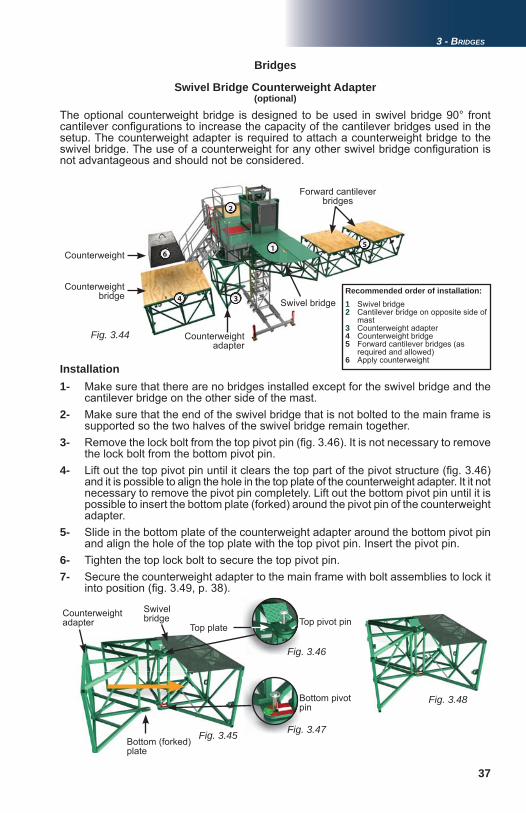
37
Fig. 3.44
Fig. 3.48
Fig. 3.45
Fig. 3.46
Fig. 3.47
1
2
34
5
6
3 - BRIDGES
Bridges
Swivel Bridge Counterweight Adapter
The optional counterweight bridge is designed to be used in swivel bridge 90° front cantilever confi gurations to increase the capacity of the cantilever bridges used in the setup. The counterweight adapter is required to attach a counterweight bridge to the swivel bridge. The use of a counterweight for any other swivel bridge confi guration is not advantageous and should not be considered.
Counterweight bridge
Counterweight
Counterweight adapter
Forward cantilever bridges
Swivel bridge
1- Make sure that there are no bridges installed except for the swivel bridge and the cantilever bridge on the other side of the mast.2- Make sure that the end of the swivel bridge that is not bolted to the main frame is supported so the two halves of the swivel bridge remain together. 3- Remove the lock bolt from the top pivot pin (fi g. 3.46). It is not necessary to remove the lock bolt from the bottom pivot pin. 4- Lift out the top pivot pin until it clears the top part of the pivot structure (fi g. 3.46) and it is possible to align the hole in the top plate of the counterweight adapter. It it not necessary to remove the pivot pin completely. Lift out the bottom pivot pin until it is possible to insert the bottom plate (forked) around the pivot pin of the counterweight adapter. 5- Slide in the bottom plate of the counterweight adapter around the bottom pivot pin and align the hole of the top plate with the top pivot pin. Insert the pivot pin.6- Tighten the top lock bolt to secure the top pivot pin. 7- Secure the counterweight adapter to the main frame with bolt assemblies to lock it into position (fi g. 3.49, p. 38).
Installation
Counterweight adapter
Swivel bridge Top pivot pin
Bottom pivot pin
Top plate
Bottom (forked) plate
(optional)
Recommended order of installation:1 Swivel bridge2 Cantilever bridge on opposite side of mast3 Counterweight adapter4 Counterweight bridge5 Forward cantilever bridges (as required and allowed)6 Apply counterweight
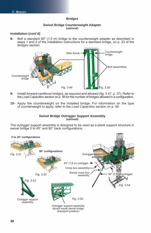
38
Fig. 3.49 Fig. 3.50
Fig. 3.54Fig. 3.53
Fig. 3.51
Fig. 3.52
Fig. 3.55
Bridges
Swivel Bridge Counterweight Adapter
8- Bolt a standard 60" (1,5 m) bridge to the counterweight adapter as described in steps 1 and 2 of the installation instructions for a standard bridge, on p. 23 of the
Bridges section.
Installation (cont’d)
9- Install forward cantilever bridges, as required and allowed (fi g. 3.47, p. 37). Refer to the Load Capacities section on p. 56 for the number of bridges allowed in a confi guration.
10- Apply the counterweight on the installed bridge. For information on the type of counterweight to apply, refer to the Load Capacities section on p. 56.
Swivel Bridge Outrigger Support Assembly
Bolt assemblies
Counterweight bridge
Main frame Counterweight bridge
The outrigger support assembly is designed to be used as a plank support structure in swivel bridge 0 to 45° and 90° back confi gurations.
0 to 45° confi gurations
90° confi gurations
63" (1,6 m) outrigger
Cross box assembly
84" (2,1 m) outriggerSwivel cross box assembly
Outrigger support assembly
Outrigger support assembly
Outrigger support assembly stored inside swivel bridge
(transport position)
3 - BRIDGES
(optional)
(optional)
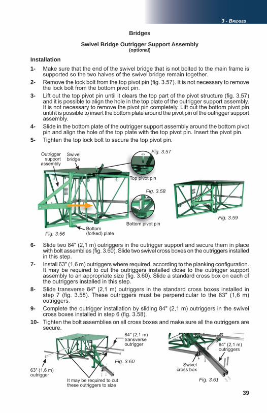
39
Fig. 3.59
Fig. 3.58
Fig. 3.60
FigFigFigFigFigFigFigFigFigFigFigFiFi . 3. .
Fig. 3.61
Fig. 3.56
Fig. 3.57
3 - BRIDGES
Bridges
Swivel Bridge Outrigger Support Assembly
Installation1- Make sure that the end of the swivel bridge that is not bolted to the main frame is supported so the two halves of the swivel bridge remain together. 2- Remove the lock bolt from the top pivot pin (fi g. 3.57). It is not necessary to remove the lock bolt from the bottom pivot pin. 3- Lift out the top pivot pin until it clears the top part of the pivot structure (fi g. 3.57) and it is possible to align the hole in the top plate of the outrigger support assembly. It is not necessary to remove the pivot pin completely. Lift out the bottom pivot pin until it is possible to insert the bottom plate around the pivot pin of the outrigger support assembly. 4- Slide in the bottom plate of the outrigger support assembly around the bottom pivot pin and align the hole of the top plate with the top pivot pin. Insert the pivot pin.5- Tighten the top lock bolt to secure the top pivot pin.
Outrigger support
assembly
Swivel bridge
Top pivot pin
Bottom pivot pinBottom (forked) plate
6- Slide two 84" (2,1 m) outriggers in the outrigger support and secure them in place with bolt assemblies (fi g. 3.60). Slide two swivel cross boxes on the outriggers installed in this step.7- Install 63" (1,6 m) outriggers where required, according to the planking confi guration. It may be required to cut the outriggers installed close to the outrigger support assembly to an appropriate size (fi g. 3.60). Slide a standard cross box on each of the outriggers installed in this step. 8- Slide transverse 84" (2,1 m) outriggers in the standard cross boxes installed in step 7 (fi g. 3.58). These outriggers must be perpendicular to the 63" (1,6 m) outriggers. 9- Complete the outrigger installation by sliding 84" (2,1 m) outriggers in the swivel cross boxes installed in step 6 (fi g. 3.58). 10- Tighten the bolt assemblies on all cross boxes and make sure all the outriggers are secure.
It may be required to cut these outriggers to size
(optional)
84" (2,1 m) transverse outrigger
63" (1,6 m) outrigger
84" (2,1 m) outriggers
Swivel cross box
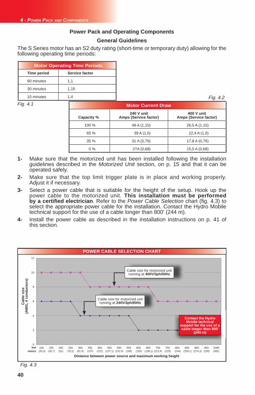
40
(30,5) (45,7) (61) (76,2) (91,4) (107) (122) (137,1) (152,4) (168) (183) (198,1) (213,4) (229) (244) (259,1) (274,3) (290) (305)
Fig. 4.3
Fig. 4.1Fig. 4.2
0
2
4
6
8
10
12
100 150 200 250 300 350 400 450 500 550 600 650 700 750 800 850 900 950 1000
Power Pack and Operating Components
1- Make sure that the motorized unit has been installed following the installation guidelines described in the Motorized Unit section, on p. 15 and that it can be operated safely. 2- Make sure that the top limit trigger plate is in place and working properly. Adjust it if necessary. 3- Select a power cable that is suitable for the height of the setup. Hook up the power cable to the motorized unit. This installation must be performed by a certifi ed electrician. Refer to the Power Cable Selection chart (fi g. 4.3) to select the appropriate power cable for the installation. Contact the Hydro Mobile technical support for the use of a cable longer than 800' (244 m). 4- Install the power cable as described in the installation instructions on p. 41 of this section.
POWER CABLE SELECTION CHART
Cab
le s
ize
(AW
G, 4
con
duct
ors)
Cable size for motorized unit running at 400V/3ph/50Hz
Distance between power source and maximum working height
feetmeters
Cable size for motorized unit running at 240V/3ph/60Hz
4 - POWER PACK AND COMPONENTS
Motor Operating Time PeriodsTime period Service factor
60 minutes 1,1
30 minutes 1,15
10 minutes 1,4
The S Series motor has an S2 duty rating (short-time or temporary duty) allowing for the following operating time periods:
General Guidelines
Contact the Hydro Mobile technical
support for the use of a cable longer than 800'
(244 m)
Motor Current Draw
Capacity %240 V unit
Amps (Service factor)400 V unit
Amps (Service factor)
100 % 46 A (1,15) 26,5 A (1,15)
65 % 39 A (1,0) 22,4 A (1,0)
35 % 31 A (0,76) 17,8 A (0,76)
0 % 27A (0,68) 15,5 A (0,68)
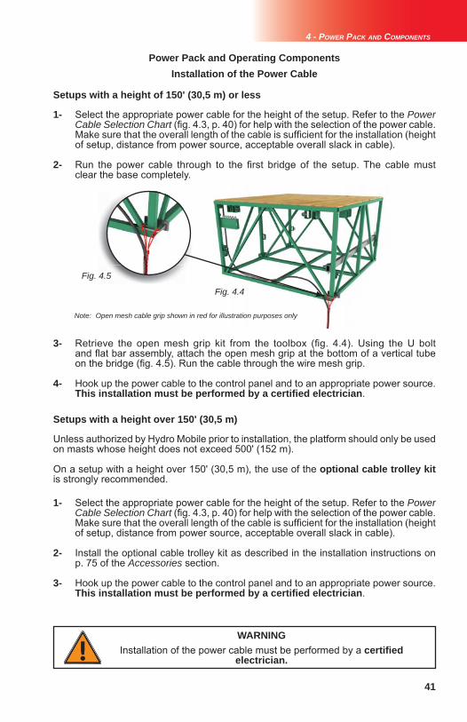
41
Fig. 4.4
Fig. 4.5
1- Select the appropriate power cable for the height of the setup. Refer to the Power Cable Selection Chart (fi g. 4.3, p. 40) for help with the selection of the power cable. Make sure that the overall length of the cable is suffi cient for the installation (height of setup, distance from power source, acceptable overall slack in cable).
2- Run the power cable through to the fi rst bridge of the setup. The cable must clear the base completely.
Setups with a height of 150' (30,5 m) or less
4 - POWER PACK AND COMPONENTS
3- Retrieve the open mesh grip kit from the toolbox (fi g. 4.4). Using the U bolt and fl at bar assembly, attach the open mesh grip at the bottom of a vertical tube on the bridge (fi g. 4.5). Run the cable through the wire mesh grip.
4- Hook up the power cable to the control panel and to an appropriate power source. This installation must be performed by a certifi ed electrician.
Power Pack and Operating Components
1- Select the appropriate power cable for the height of the setup. Refer to the Power Cable Selection Chart (fi g. 4.3, p. 40) for help with the selection of the power cable. Make sure that the overall length of the cable is suffi cient for the installation (height of setup, distance from power source, acceptable overall slack in cable).
2- Install the optional cable trolley kit as described in the installation instructions on p. 75 of the Accessories section.
3- Hook up the power cable to the control panel and to an appropriate power source. This installation must be performed by a certifi ed electrician.
Setups with a height over 150' (30,5 m)
Unless authorized by Hydro Mobile prior to installation, the platform should only be used on masts whose height does not exceed 500' (152 m).
On a setup with a height over 150' (30,5 m), the use of the optional cable trolley kitis strongly recommended.
Installation of the Power Cable
WARNINGInstallation of the power cable must be performed by a certifi ed
electrician.
Note: Open mesh cable grip shown in red for illustration purposes only
42
Power Pack and Operating Components
4 - POWER PACK AND COMPONENTS
1- Prepare the motorized unit by following the general guidelines, on p. 40.2- Connect the power cable to a safe and reliable power source (from the building or a generator). This installation must be performed by an electrician. Make sure that the input voltage is within the required power range values. Refer to p. 10 and p. 11 of the Motorized Unit section for more information on the input power range.3- Turn on the main disconnect switch.4- Pull out the emergency stop button (fi g. 6.1, p. 43) to power on the display panel. If the display panel does not turn on after a short period of time, make sure that the power cable is properly connected to both the power source and to the motorized unit. If the cable is connected, verify the phase selector and make sure the appropriate phase has been selected. The phase selector should be at the left (1) or right (2) position. The middle (0) position is neutral and will prevent the unit and panel from powering on. If the display panel still does not turn on, push in the emergency stop button, turn off the main disconnect switch and contact a certifi ed electrician. 5- Once powered on, unlock the display panel as described in the instructions on p. 44 of the Control Panel section.6- If the motorized unit is used in a multiple unit confi guration, make sure that the inclinometer has been connected to the proper port into the control panel and that the inclinometer option has been enabled on the display panel. If required, install an optional communication cable and enable the communication cable on the display panel. Make sure that the feedback cable has been installed and is working properly. Refer to p. 20 and p. 22 of the Safety Devices section for more information about inclinometers and feedback cables. For more information about enabling options on the display panel, refer to the Control Panel section on p. 43.
Motorized unit startup procedure
1- If the motorized unit was used in a multiple unit confi guration, make sure that no slope alert is displayed on the control panel screen and that the structure is level.2- Bring the motorized unit down to base level. 3- In order to avoid unauthorized operation of the motorized unit, perform the following steps to lock the control panel: a. Return to the main menu on the display screen b. Press twice on the OK button under the display screen to reach the access code entry screen c. Press on one of the bottom left buttons to log out of the panel4- Push in the emergency stop button to shut down the control panel. 5- Turn off the main disconnect switch.6- Before transporting or storing the unit for any signifi cant length of time, refer to instructions on p. 77 of the Transport, Storage and Maintenance section.
Motorized unit shutdown procedure
The current in the hand tool power outlets is shut off when the motorized unit is moving.
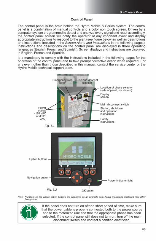
43
Fig. 6.1
Fig. 6.2
5 - CONTROL PANEL
Control Panel
The control panel is the brain behind the Hydro Mobile S Series system. The control panel is a combination of manual controls and a color non touch screen. Driven by a computer system programmed to detect and analyze every signal and react accordingly, the control panel screen will notify the operator of any important event and display appropriate instructions to respond to the alert (see fi gure below as well as descriptions and instructions included in the Screen Alerts and Instructions in the following pages). Instructions and descriptions on the control panel are displayed in three operating languages (English, French and Spanish). Screen displays and instructions are displayed in English, French and Spanish. It is mandatory to comply with the instructions included in the following pages for the operation of the control panel and to take prompt corrective action when required. For any event other than those described in this manual, contact the service center or the Hydro Mobile technical support team.
Startup, shutdown and operation instructions
Display screen
Emergency stop button
Main disconnect switch
Safety instructions
If the panel does not turn on after a short period of time, make sure that the power cable is properly connected both to the power source and to the motorized unit and that the appropriate phase has been selected. If the control panel still does not turn on, turn off the main
disconnect switch and contact a certifi ed electrician.
Note: Numbers on the above option buttons are displayed as an example only. Actual messages displayed may differ from picture.
Rise and descent selector
Power outlets
(120 VAC and 220
VAC)
Location of phase selector (side of panel, not shown)
111111111 22222222222 333333333333 4444444444444
Option buttons
Navigation buttonPower indicator light
OK button
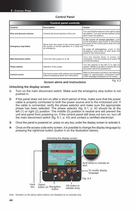
44
Fig. 6.3
Fig. 6.4
Control panel controlsControl Description Action
Rise and descent selector Controls the travel direction of the unit. Turn and hold the selector to the right to raise the platform. Turn and hold the selector to the left to lower the platform.
Emergency stop buttonShuts down the power to the control panel in the course of normal operation or in case of an emergency.
In the course of normal operation, push in the emergency stop button to shut down the power to the control panel when the unit is not in use.
In case of emergency, push in the emergency stop button to shut down the power to the control panel.
Main disconnect switch Turns the main power on or off.Turn the handle down to power on (clockwise). Turn the handle up to power off (counterclockwise).
Phase selector Selection of the phase.Turn the selector to the left (1) or right (2) position. Middle (0) position is neutral; the unit and panel cannot be powered on.
Control screen Non touch screen (with options and navigation buttons) displaying alerts and instructions.
Refer to information included in the following pages to appropriately understand each of the messages displayed on the screen.
Control Panel
Screen alerts and instructionsUnlocking the display screen1- Turn on the main disconnect switch. Make sure the emergency stop button is not pushed in.
2- If the panel does not turn on after a short period of time, make sure that the power cable is properly connected to both the power source and to the motorized unit. If the cable is connected, verify the phase selector and make sure the appropriate phase has been selected. The phase selector (fi g. 6.1, p. 43 should be at the left (1) or right (2) position. The middle (0) position is neutral and will prevent the unit and panel from powering on. If the control panel still does not turn on, turn off the main disconnect switch (fi g. 6.1, p. 43) and contact a certifi ed electrician.
3- Once the panel is powered on, press on any key under the display screen to activate it.
4- Once on the access code entry screen, it is possible to change the display language by pressing the rightmost button (button 4 on the illustration below).
Note: Numbers on the above option buttons are displayed as an example only.
5 - CONTROL PANEL
111111111 22222222222 333333333333 4444444444444
Input box
To modify display language
Navigation button
Unlocking the display screen
ALM blinks to indicate an alert
OK button to validate entry
Option button (4)

45
Fig. 6.5
Fig. 6.6
5 - CONTROL PANEL
Control Panel
Main menu screen
Screen Description Access level
F1 – Status info Information on the status of the unit and its components (door sensors, inclinometer, total runtime hours, etc.)
Operator
F2 – Alarms Information on any event detected by the control panel that could prevent the unit and its components to operate safely
Operator
F3 – Inputs and outputs
Status of various controls, sensors and switches linked to input and output ports
Operator
F4 – Confi guration Screens allowing the modifi cation of certain options for the unit or the installation (enabling door sensors, enabling inclinometers, modifying user-level password, resetting maintenance runtime counter, etc.)
Erector/Dismantler(level 1)
Pressing twice on OK button
Entry-level access page to log out and lock panel
Operator
Screen alerts and instructions
5- If an event is detected by the panel, the ALM rectangle will blink (above button 3 in fi g. 6.4) to indicate it. The display screen must be unlocked to display the alert info screen.
6- To enter the operating access code (default “10”), press on the OK button. Once the input box is blinking, use the UP and DOWN arrows (on the navigation button) to change the value, then press OK to unlock the control panel. The default operating access code can be changed by the installer.
7- Once the control panel is unlocked, the screen displays the main menu screen. Press on the appropriate option button to go to the selected option.
F1 – Status info
Access level: OperatorAccess level: Operator
1- Press F1 on the main menu screen (button 1 on the main menu screen display example in fi g. 6.5).
2- Change display pages with the option buttons (buttons 1 and 2 in fi g. 6.7, p. 46
3- Press the BACK button (button 4 in fi g. 6.7, p. 46) to return to the main menu screen.
This two-page section displays general information about the unit and the installation.
111111111 22222222222 333333333333 4444444444444
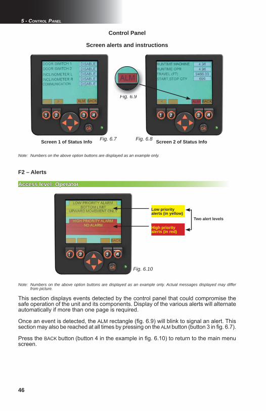
46
Fig. 6.7 Fig. 6.8
Fig. 6.10
Fig. 6.9
Control Panel
5 - CONTROL PANEL
Screen alerts and instructions
Note: Numbers on the above option buttons are displayed as an example only.
Screen 1 of Status Info Screen 2 of Status Info
This section displays events detected by the control panel that could compromise the safe operation of the unit and its components. Display of the various alerts will alternate automatically if more than one page is required.
Once an event is detected, the ALM rectangle (fi g. 6.9) will blink to signal an alert. This section may also be reached at all times by pressing on the ALM button (button 3 in fi g. 6.7).
Press the BACK button (button 4 in the example in fi g. 6.10) to return to the main menu screen.
F2 – Alerts
Access level: OperatorAccess level: Operator
Note: Numbers on the above option buttons are displayed as an example only. Actual messages displayed may differ from picture.
111111111 22222222222 333333333333 4444444444444 111111111 22222222222 333333333333 4444444444444
111111111 22222222222 333333333333 4444444444444
Low priority alerts (in yellow)
High priority alerts (in red)
Two alert levels
Fi 6 9
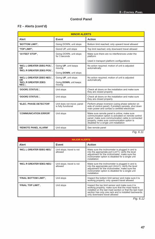
47
Fig. 6.11
Fig. 6.12
5 - CONTROL PANEL
Control Panel
MINOR ALERTS
Alert Event Action
‘BOTTOM LIMIT’, Going DOWN, unit stops Bottom limit reached; only upward travel allowed
‘TOP LIMIT’, Goind UP, unit stops Top limit reached; only downward travel allowed
‘10 FEET STOP’, Going DOWN, unit stops for 3 seconds
Make sure there are no interferences under the platform
Used in transport platform confi gurations
‘INCL L GREATER 2DEG POS.’,OR‘INCL R GREATER 2DEG POS.’,
Going UP, unit keeps moving
Going DOWN, unit stops
No action required; motion of unit is adjusted automatically
‘INCL L GREATER 2DEG NEG.’,OR‘INCL R GREATER 2DEG NEG.’,
Going UP, unit stops
Going DOWN, unit keeps moving
No action required; motion of unit is adjusted automatically
‘DOOR1 STATUS.’, Unit stops Check all doors on the installation and make sure they are closed properly
‘DOOR2 STATUS.’, Unit stops Check all doors on the installation and make sure they are closed properly
‘ELEC. PHASE DETECTOR’ Unit does not move; panel is fully functional
Perform phase inversion (using phase selector on side of control panel); if problem persists, shut down main power and contact a certifi ed electrician
‘COMMUNICATION ERROR’ Unit stops Make sure remote panel is online; make sure communication option is activated on remote control panel; make sure communication cable is connected properly; make sure communication option is disabled for a single unit installation
‘REMOTE PANEL ALARM’ Unit stops See remote panel
F2 – Alerts (cont’d)
MAJOR ALERTS
Alert Event Action
‘INCL L GREATER 5DEG NEG.’ Unit stops; travel is not allowed
Make sure the inclinometer is plugged in and is into the appropriate port (LEFT); verify the level adjustment for the inclinometer; make sure the inclinometer option is disabled for a single unit installation
‘INCL R GREATER 5DEG NEG.’ Unit stops; travel is not allowed
Make sure the inclinometer is plugged in and is into the appropriate port (RIGHT); verify the level adjustment for the inclinometer; make sure the inclinometer option is disabled for a single unit installation
‘FINAL BOTTOM LIMIT’, Unit stops Inspect the bottom limit sensor and make sure it is working properly; only upward travel allowed
‘FINAL TOP LIMIT’, Unit stops Inspect the top limit sensor and make sure it is working properly; make sure that the mast head is installed on the last mast section or that the last mast section has only one rack and is installed backwards; only downward travel allowed

48
Fig. 6.13
Fig. 6.14 Fig. 6.16
Fig. 6.15
Screen alerts and instructions
Control Panel
5 - CONTROL PANEL
F3 – Inputs and outputs
This section displays information about the various controls, sensors and switches linked to the input and output ports of the control panel. A black circle will indicate that the control panel receives a signal from a sensor or sends a signal to an actuator. Other information will be displayed in values. These pages are mainly useful for troubleshooting operations to provide information on the condition of the unit and the setup to a remote qualifi ed technician.
Access level: OperatorAccess level: Operator
1- Press the F3 button on the main menu screen (button 3 in fi g. 6.5, p. 45). 2- Change display pages with the option buttons (buttons 1 and 2 in fi g. 6.13).3- Press the BACK button (button 4 in fi g. 6.13) to return to the main menu screen.
Note: Numbers on the above option buttons are displayed as an example only.
11111111 2222222222 33333333333 444444444444
Access level: Erector / DismantlerAccess level: Erector / Dismantler
F4 – Confi guration
1- Press the F4 button on the main menu screen (button 4 in fi g. 6.5, p. 45). 2- On the access code entry page, press on the OK button. Once the input box is blinking, use the UP and DOWN arrows (on the navigation button) to change the value (access code available only to the erector/dismantler), then press OK to access the confi guration options section pages.3- Change display pages with the option buttons (buttons 1 and 2 in fi g. 6.13).4- Use the UP and DOWN arrows on the navigation button to reach the box to be modifi ed. 5- Press the OK button to select the box to be modifi ed. 6- Once the selected box is blinking, use the UP and DOWN arrows on the navigation button to change the value displayed in the box.
This four-page section includes: one access code entry page for this section (accessible only to Erector / Dismantler level) and two pages for the modifi cation of setup confi guration options. The last page of the section is an access code entry page giving access to options available only to a qualifi ed technician.
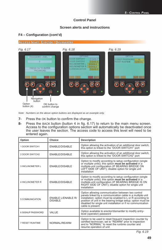
49
Fig. 6.18Fig. 6.17
Fig. 6.19
Fig. 6.19
5 - CONTROL PANEL
Control Panel
Screen alerts and instructions
7- Press the OK button to confi rm the change. 8- Press the BACK button (button 4 in fi g. 6.17) to return to the main menu screen. Access to the confi guration options section will automatically be deactivated once the user leaves the section. The access code to access this level will need to be entered again.
F4 – Confi guration (cont’d)
Access level: Erector / DismantlerAccess level: Erector / Dismantler
111111111 22222222222 33333333333 444444444444 111111111 22222222222 33333333333 444444444444
OK button to confi rm change
Note: Numbers on the above option buttons are displayed as an example only.
Option Choice Description
1 DOOR SWITCH1 ENABLE/DISABLE Option allowing the activation of an additional door switch; this option is linked to the “DOOR SWITCH1” port
2 DOOR SWITCH2 ENABLE/DISABLE Option allowing the activation of an additional door switch; this option is linked to the “DOOR SWITCH2” port
3 INCLINOMETER L ENABLE/DISABLE
Option to modify according to setup confi guration (single or multiple units); this option must be activated in a multiple-unit confi guration (IF BEARING BRIDGE ON LEFT SIDE OF UNIT); disable option for single unit installation
4 INCLINOMETER R ENABLE/DISABLE
Option to modify according to setup confi guration (single or multiple units); this option must be activated in a multiple-unit confi guration (IF BEARING BRIDGE IS ON RIGHT SIDE OF UNIT); disable option for single unit installation
5 COMMUNICATION ENABLE L/ENABLE R/ DISABLE
Option allowing communication between two control panels linked by a communication cable in a multiple unit installation; option must be enabled to L or R according to position of unit in the bearing bridge setup; option must be disabled for single unit installation or if no communication cable is present
6 SIGNUP PASSWORD VALUE Option available to erector/dismantler to modify entry-level (operator) password
7 RESET RUNTIME NORMAL/REARMOption to be used to reset frequent inspection counter by certifi ed technician; set to “REARM” prior to inspection and to “NORMAL” to reset the runtime counter and resume operation of unit
Option button (4)
Navigation button
111111111 22222222222 33333333333 444444444444

50
xxxxxxxxxxx
Fig. 6.2
Fig. 6.1
Mast sections
Installation
1- Make sure that the motorized unit is positioned properly. Refer to p. 15 of the Motorized Unit section for more information.
2- Refer to regulations governing distances between the mast climbing work platform system and electrical lines.
3- Remove the mast head (fi g. 6.2).
4- Using an optional jib arm (see p. 73 of the Accessories section) or any other lifting device such as a crane or a forklift, raise the next mast section and insert it on top of the bottom mast section.
5- Make sure that the rack of the mast section is on the rear side (fig. 6.2) and aligned with the rack on the bottom mast section. It is recommended to handle mast sections carefully so as not to damage the mast rack(s).
6- Make sure the spring pins on the racks are properly aligned and that the mast sections are connected together (fi g. 6.1).
7- Using 1"-8 x 8" GR8 bolts and 1" GR8 lock nuts, bolt all four corners together, making sure the bolt heads are facing down. Tighten the four bolt and nut assemblies to 150 lb-ft (203 N-m) of torque to secure the mast section in place.
8- Repeat steps 4 through 7 for each mast section.
Mast head
Mast section
Bottom mast section
Incorrect Correct
Rack to rack alignment
Rear side
6 - MASTS AND MAST TIES

51
6 - MASTS AND MAST TIES
Storage and transport
1- Mast sections must be handled carefully, namely so as not to damage the mast rack.
2- Mast sections can be stored vertically or horizontally, lying on the side which has no rack, away from work areas and construction traffi c.
3- If mast sections are to be stored on the platform during erecting and dismantling, make sure they are equally distributed on each side of the mast to ensure good balance. Refer to the Load Capacities section on p. 56 to avoid overloading the platform.
4- Mast sections can be transported vertically or horizontally, lying on a side which has no rack.
WARNINGFailure to grease mast rack properly and in a timely fashion may
cause premature wear of rack and pinion and provoke down time, even lead to serious injury or death.
Lifting capacity of the mast head
The mast head must not be used to lift a setup exceeding one motorized unit, a width of 50' (15,2 m) or 8 x 60" (1,5 m) bridges and a height of 18' (5,5 m) or two masts.
The mast head can also be used when using a crane to lift mast sections pre-assembled in 45' (13,7 m) sections. It is recommended to adhere to local regulations for the proper way to lift and handle equipment.
Mast sections can be pre-assembled in 45' (13,7 m) sections to speed up assembly when using a crane. It is recommended to adhere to local regulations
for the proper way to lift and handle equipment.
9- Make sure that the rack is suffi ciently greased along the whole length of the mast. On initial setup and subsequently after every eight hours of cumulative runtime
(with unit traveling up and down the mast), grease must be applied to the rack(s) and gears, from the top of the setup down. For more information, refer to the daily inspection checklist recommended for this motorized unit. Grease must be allowed to stand for 2-3 hours before the motorized unit is used again. Use an open gear lubricant recommended by Hydro Mobile. Refer to p. 78 of the Transport, Storage and Maintenance section for more information on the appropriate lubrication method.
10- Install the top limit proximity trigger plate on the next to last mast section from the top.
11- Install the mast head on the last mast section and keep it in place until the setup is dismantled. If a mast head is not used, make sure that last mast section has only one rack and is installed backwards, with the rack facing the work.
Mast sections
Installation (cont’d)
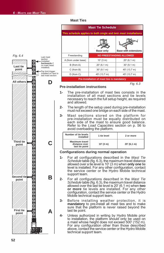
52
Fig. 6.4
Fig. 6.3
Mast Ties
1- The pre-installation of mast ties consists in the installation of all mast sections and tie levels necessary to reach the full setup height, as required and allowed. 2- The length of the setup used during pre-installation must not exceed one bridge on each side of the mast. 3- Mast sections stored on the platform for pre-installation must be equally distributed on each side of the mast to ensure good balance. Refer to the Load Capacities section on p. 56 to avoid overloading the platform.
First tie point
Second tie point
Third tie point
All others
Mast Tie Schedule
This schedule applies to both single and twin mast installations
Base only Base with extensions
Freestanding NO FREESTANDING ALLOWED
A (from under base) 10' (3 m) 20' (6,1 m)
B (from A) 20' (6,1 m) 30' (9,1 m)
C (from B) 30' (9,1 m) 45' (13,7 m)
D (from C) 45' (13,7 m) 45' (13,7 m)
Pre-installation of mast ties is mandatory
6 - MASTS AND MAST TIES
Last tie point
Last mast section(installed backwards if no mast head installed)
A
B
C
D
1- For all configurations described in the Mast Tie Schedule table (fi g. 6.3), the maximum travel distance allowed over a tie level is 10' (3 m) when only one tie level is installed. For any other confi guration, contact the service center or the Hydro Mobile technical support team. 2- For all configurations described in the Mast Tie Schedule table (fi g. 6.3), the maximum travel distance allowed over the last tie level is 20' (6.1 m) when two or more tie levels are installed. For any other confi guration, contact the service center or the Hydro Mobile technical support team.3- Before install ing weather protection, it is mandatory to pre-install all mast ties and to make sure that the platform is never raised beyond the last tie point. 4- Unless authorized in writing by Hydro Mobile prior to installation, the platform should only be used on a mast whose height does not exceed 500' (152 m). For any confi guration other than those described above, contact the service center or the Hydro Mobile technical support team.
Pre-installation instructions
Confi gurations during normal operation
Number of tie levels installed 1 tie level 2 or more
Maximum travel distance over
last tie point10' (3 m) 20' (6,1 m)
Top limit trigger installed on next to last mast section
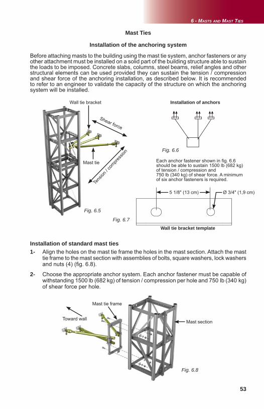
53
Fig. 6.5
Fig. 6.6
Fig. 6.8
Fig. 6.7
6 - MASTS AND MAST TIES
Before attaching masts to the building using the mast tie system, anchor fasteners or any other attachment must be installed on a solid part of the building structure able to sustain the loads to be imposed. Concrete slabs, columns, steel beams, relief angles and other structural elements can be used provided they can sustain the tension / compression and shear force of the anchoring installation, as described below. It is recommended to refer to an engineer to validate the capacity of the structure on which the anchoring system will be installed.
Installation of the anchoring system
Wall tie bracket
Tens
ion / c
ompre
ssion
Installation of anchors
Each anchor fastener shown in fi g. 6.6 should be able to sustain 1500 lb (682 kg) of tension / compression and 750 lb (340 kg) of shear force. A minimum of six anchor fasteners is required.
Shear force
Mast Ties
Mast tie
1- Align the holes on the mast tie frame the holes in the mast section. Attach the mast tie frame to the mast section with assemblies of bolts, square washers, lock washers and nuts (4) (fi g. 6.8).
2- Choose the appropriate anchor system. Each anchor fastener must be capable of withstanding 1500 lb (682 kg) of tension / compression per hole and 750 lb (340 kg) of shear force per hole.
Installation of standard mast ties
Mast section
Mast tie frame
Toward wall
5 1/8" (13 cm) Ø 3/4" (1,9 cm)
Wall tie bracket template
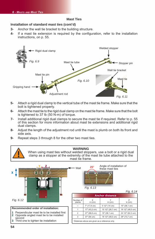
54
Fig. 6.99
Fig. 6.10
Fig. 6.11
Fig. 6.14
Fig. 6.126.12
X
Y Z
Fig. 6.13
1 23
Mast tie tube
Rigid dual clampWelded stopper
Mast tie pin
Adjustment rod
Stopper pin
Gripping hand
Mast Ties
3- Anchor the wall tie bracket to the building structure.4- If a mast tie extension is required by the confi guration, refer to the installation instructions, on p. 55.
Wall
Anchor distanceNumber of
planksX
in (cm)Y
in (cm)Z
in (cm)
─ 7" (17,8 cm) 5 1/2" (14 cm) 15" (38,1 cm)
1 17" (43,2 cm) 10 1/2" (26,7 cm) 19 1/2" (49,5 cm)
2 27" (68,6 cm) 15" (38,1 cm) 24 1/2" (62,2 cm)
3 37" (94 cm) 19 1/2" (49,5 cm) 29" (73,7 cm)
Distances above are given as a reference only.
5- Attach a rigid dual clamp to the vertical tube of the mast tie frame. Make sure that the bolt is tightened properly.6- Attach the mast tie to the rigid dual clamp on the mast tie frame. Make sure that the bolt is tightened to 37 lb (50 N-m) of torque. 7- Install additional rigid dual clamps to secure the mast tie if required. Refer to p. 55 of this section for more information about mast tie extensions and additional rigid dual clamps.8- Adjust the length of the adjustment rod until the mast is plumb on both its front and side axis. 9- Repeat steps 3 through 8 for the other two mast ties.
Installation of standard mast ties (cont’d)
25°
6 - MASTS AND MAST TIES
WARNINGWhen using mast ties without welded stoppers, use a bolt or a rigid dual clamp as a stopper at the extremity of the mast tie tube attached to the
mast tie frame.
Angle of installation of these mast ties
Recommended order of installation:1 Perpendicular mast tie to be installed fi rst2 Opposite angled mast tie to be installed second3 Third one to tighten tie installation
Wall tie bracket
Mast tie
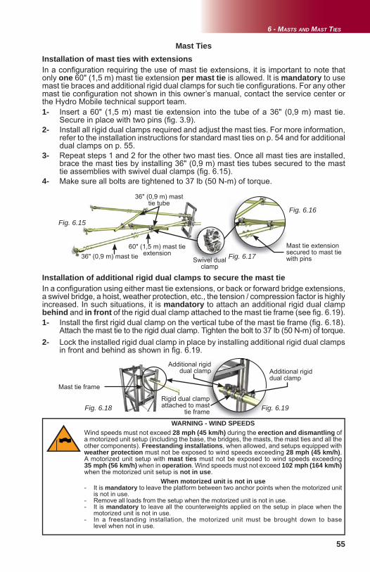
55
Fig. 6.18 Fig. 6.19
Fig. 6.16
Fig. 6.15
Fig. 6.17
6 - MASTS AND MAST TIES
1- Install the fi rst rigid dual clamp on the vertical tube of the mast tie frame (fi g. 6.18). Attach the mast tie to the rigid dual clamp. Tighten the bolt to 37 lb (50 N-m) of torque.2- Lock the installed rigid dual clamp in place by installing additional rigid dual clamps in front and behind as shown in fi g. 6.19.
Rigid dual clamp attached to mast
tie frame
Additional rigid dual clamp
Installation of additional rigid dual clamps to secure the mast tie
36" (0,9 m) mast tie
Mast tie frame
Mast Ties
WARNING - WIND SPEEDSWind speeds must not exceed 28 mph (45 km/h) during the erection and dismantling of a motorized unit setup (including the base, the bridges, the masts, the mast ties and all the other components). Freestanding installations, when allowed, and setups equipped with weather protection must not be exposed to wind speeds exceeding 28 mph (45 km/h). A motorized unit setup with mast ties must not be exposed to wind speeds exceeding 35 mph (56 km/h) when in operation. Wind speeds must not exceed 102 mph (164 km/h) when the motorized unit setup is not in use.
When motorized unit is not in use- It is mandatory to leave the platform between two anchor points when the motorized unit is not in use.- Remove all loads from the setup when the motorized unit is not in use. - It is mandatory to leave all the counterweights applied on the setup in place when the motorized unit is not in use. - In a freestanding installation, the motorized unit must be brought down to base level when not in use.
Installation of mast ties with extensionsIn a confi guration requiring the use of mast tie extensions, it is important to note that only one 60" (1,5 m) mast tie extension per mast tie is allowed. It is mandatory to use mast tie braces and additional rigid dual clamps for such tie confi gurations. For any other mast tie confi guration not shown in this owner’s manual, contact the service center or the Hydro Mobile technical support team.
In a confi guration using either mast tie extensions, or back or forward bridge extensions, a swivel bridge, a hoist, weather protection, etc., the tension / compression factor is highly increased. In such situations, it is mandatory to attach an additional rigid dual clamp behind and in front of the rigid dual clamp attached to the mast tie frame (see fi g. 6.19).
60" (1,5 m) mast tie extension
36" (0,9 m) mast tie tube
1- Insert a 60" (1,5 m) mast tie extension into the tube of a 36" (0,9 m) mast tie. Secure in place with two pins (fi g. 3.9).2- Install all rigid dual clamps required and adjust the mast ties. For more information, refer to the installation instructions for standard mast ties on p. 54 and for additional dual clamps on p. 55. 3- Repeat steps 1 and 2 for the other two mast ties. Once all mast ties are installed, brace the mast ties by installing 36" (0,9 m) mast ties tubes secured to the mast tie assemblies with swivel dual clamps (fi g. 6.15). 4- Make sure all bolts are tightened to 37 lb (50 N-m) of torque.
Swivel dual clamp
Additional rigid dual clamp
Mast tie extension secured to mast tie with pins
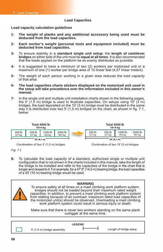
56
Fig. 7.1
Load Capacities
WARNINGTo ensure safety at all times on a mast climbing work platform system,
bridges should not be loaded beyond their maximum rated weight capacities. In addition, to prevent a mast climbing work platform system from stalling because of an overload, maximum rated load capacities of the motorized unit(s) should be observed. Overloading a mast climbing
work platform system could result in serious injury or death.
Make sure that there is never two workers standing on the same plank outrigger at the same time.
LEGEND
5' (1,5 m) bridge assembly
1- The weight of planks and any additional accessory being used must be deducted from the load capacities.2- Each worker’s weight (personal tools and equipment included) must be deducted from load capacities. 3- To ensure stability in a standard single unit setup, the length of cantilever bridges on either side of the unit must be equal at all times. It is also recommended that the loads applied on the platform be as evenly distributed as possible.
4- It is suggested to have a minimum of two (2) workers per motorized unit or a maximum of one (1) worker per bridge area of 15 linear feet (4,57 linear meters).
5- The weight of each person working in a given area reduces the load capacity of that area.
6- The load capacities charts stickers displayed on the motorized unit used in the setup will take precedence over the information included in this owner’s manual. 7- In the single unit and multiple unit installation charts shown in the following pages, the 5' (1,5 m) bridge is used to illustrate capacities. On setups using 10' (3 m) bridges, the load deposited on the 10' (3 m) bridge must be distributed in the same way it is distributed over two 5' (1,5 m) bridges on the chart, as shown in fi g. 7.1, below.
Load capacity calculation guidelines
Length of bridge setup
8- To calculate the load capacity of a standard, authorized single or multiple unit confi guration that is not shown in the charts included in this manual, take the length of the bridge to be installed and refer to the capacities of the bridge in the chart that is longer and closest to it. For example, for a 47' 6" (14,5 m) bearing bridge, the load capacities of a 50' (16 m) bearing bridge would be used.
500 lb227 kg
500 lb227 kg
1000 lb454 kg
2000 lb907 kg
500 lb227 kg
500 lb227 kg
1000 lb454 kg
2000 lb907 kg
Total 4000 lb1814 kg
Total 4000 lb1814 kg
Combination of four 5' (1,5 m) bridges Combination of two 10' (3 m) bridges
20' (6,1 m) 20' (6,1 m)
7 - LOAD CAPACITIES
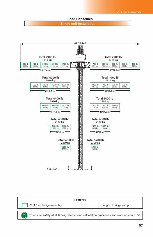
57
Fig. 7.2
7 - LOAD CAPACITIES
Single unit installation
To ensure safety at all times, refer to load calculation guidelines and warnings on p. 56.
Load Capacities
LEGEND
5' (1,5 m) bridge assembly Length of bridge setup
Total 2900 lb1315 kg
Total 2900 lb1315 kg
300 lb136 kg
1700 lb771 kg
300 lb136 kg
300 lb136 kg
300 lb136 kg
1700 lb771 kg
300 lb136 kg
300 lb136 kg
300 lb136 kg
300 lb136 kg
500 lb227 kg
500 lb227 kg
1000 lb454 kg
2000 lb907 kg
2000 lb907 kg
1000 lb454 kg
500 lb227 kg
500 lb227 kg
Total 4000 lb1814 kg
Total 4000 lb1814 kg
Total 4400 lb1996 kg
Total 4400 lb1996 kg
1400 lb635 kg
1400 lb635 kg
1600 lb726 kg
1600 lb726 kg
1400 lb635 kg
1400 lb635 kg
Total 4800 lb2177 kg
Total 4800 lb2177 kg
2400 lb1089 kg
2400 lb1089 kg
2400 lb1089 kg
2400 lb1089 kg
Total 5200 lb2359 kg
Total 5200 lb2359 kg
5200 lb2359 kg
5200 lb2359 kg
25' (7,6 m) 25' (7,6 m)
20' (6,1 m) 20' (6,1 m)
15' (4,6 m) 15' (4,6 m)
10' (3 m) 10' (3 m)
60' (18,3 m)
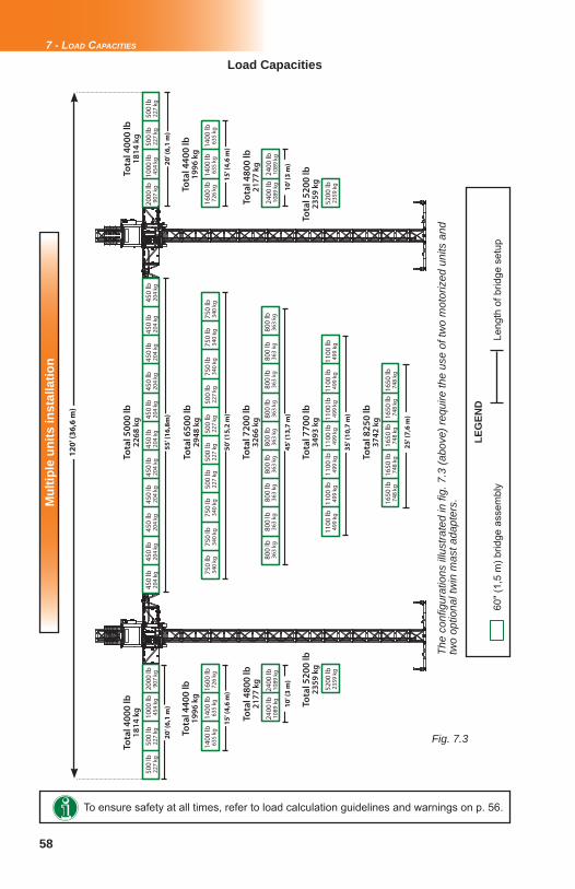
58
Fig. 7.3
Mul
tiple
uni
ts in
stal
latio
n
The
confi
gur
atio
ns il
lust
rate
d in
fi g.
7.3
(abo
ve) r
equi
re th
e us
e of
two
mot
oriz
ed u
nits
and
tw
o op
tiona
l tw
in m
ast a
dapt
ers.
LEG
END
60" (
1,5
m) b
ridge
ass
embl
yLe
ngth
of b
ridge
set
up
Tota
l 400
0 lb
1814
kg
500
lb22
7 kg
20
' (6
,1 m
)
500
lb22
7 kg
1000
lb45
4 kg
2000
lb90
7 kg
2000
lb90
7 kg
1000
lb45
4 kg
500
lb22
7 kg
500
lb22
7 kg
750
lb34
0 kg
750
lb34
0 kg
750
lb34
0 kg
500
lb22
7 kg
500
lb22
7 kg
500
lb22
7 kg
500
lb22
7 kg
750
lb34
0 kg
750
lb34
0 kg
750
lb34
0 kg
1400
lb63
5 kg
1400
lb63
5 kg
1600
lb72
6 kg
800
lb36
3 kg
800
lb36
3 kg
800
lb36
3 kg
800
lb36
3 kg
800
lb36
3 kg
800
lb36
3 kg
800
lb36
3 kg
800
lb36
3 kg
800
lb36
3 kg
1600
lb72
6 kg
1400
lb63
5 kg
1400
lb63
5 kg
2400
lb10
89 k
g24
00 lb
1089
kg
2400
lb10
89 k
g24
00 lb
1089
kg
1100
lb49
9 kg
1100
lb49
9 kg
1100
lb49
9 kg
1100
lb49
9 kg
1100
lb49
9 kg
1100
lb49
9 kg
1100
lb49
9 kg
5200
lb23
59 k
g52
00 lb
2359
kg
1650
lb74
8 kg
1650
lb74
8 kg
1650
lb74
8 kg
1650
lb74
8 kg
1650
lb74
8 kg
Tota
l 650
0 lb
2948
kg
Tota
l 400
0 lb
1814
kg
Tota
l 440
0 lb
1996
kg
Tota
l 720
0 lb
3266
kg
Tota
l 440
0 lb
1996
kg
Tota
l 480
0 lb
2177
kg
Tota
l 770
0 lb
3493
kg
Tota
l 480
0 lb
2177
kg
Tota
l 520
0 lb
2359
kg
Tota
l 825
0 lb
3742
kg
Tota
l 520
0 lb
2359
kg
12
0' (
36
,6 m
)
20
' (6
,1 m
)5
5' (
16
,8m
)
15
' (4
,6 m
)1
5' (
4,6
m)
45
' (1
3,7
m)
10
' (3
m)
10
' (3
m)
35
' (1
0,7
m)
25
' (7
,6 m
)
7 - LOAD CAPACITIES
Load Capacities
50
' (1
5,2
m)
450
lb20
4 kg
450
lb20
4 kg
450
lb20
4 kg
450
lb20
4 kg
450
lb20
4 kg
450
lb20
4 kg
450
lb20
4 kg
450
lb20
4 kg
450
lb20
4 kg
450
lb20
4 kg
Tota
l 500
0 lb
2268
kg
450
lb20
4 kg
To ensure safety at all times, refer to load calculation guidelines and warnings on p. 56.
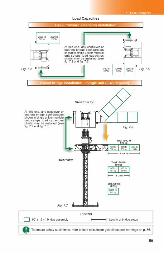
59
Fig. 7.4 Fig. 7.5
Fig. 7.6
Fig. 7.7
7 - LOAD CAPACITIES
Back / forward extension installation
Load Capacities
2000 lb907 kg
2000 lb907 kg
500 lb227 kg
1000 lb454 kg
2000 lb907 kg
At this end, any cantilever or bearing bridge configuration shown in single unit or multiple unit setups load capacities charts may be installed (see fi g. 7.2 and fi g. 7.3)
Swivel bridge installation – Single unit (0-45 degrees)
700 lb318 kg
300 lb136 kg
300 lb136 kg
1000 lb454 kg
500 lb227 kg
2000 lb907 kg
15' (4,6 m)
10' (3 m)
Total 1300 lb590 kg
Total 1500 lb680 kg
Total 2000 lb907 kg
At this end, any cantilever or bearing bridge configuration shown in single unit or multiple unit setups load capacities charts may be installed (see fi g. 7.2 and fi g. 7.3)
View from top
Rear view
To ensure safety at all times, refer to load calculation guidelines and warnings on p. 56.
LEGEND
60" (1,5 m) bridge assembly Length of bridge setup
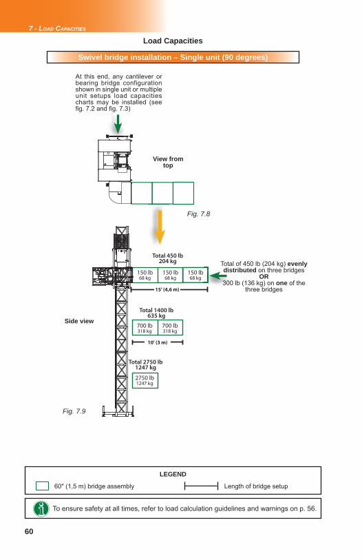
60
Fig. 7.8
Fig. 7.9
7 - LOAD CAPACITIES
Load Capacities
Swivel bridge installation – Single unit (90 degrees)
At this end, any cantilever or bearing bridge configuration shown in single unit or multiple unit setups load capacities charts may be installed (see fi g. 7.2 and fi g. 7.3)
150 lb68 kg
700 lb318 kg
700 lb318 kg
2750 lb1247 kg
Total 450 lb204 kg
15' (4,6 m)
Total 1400 lb635 kg
10' (3 m)
Total 2750 lb1247 kg
150 lb68 kg
150 lb68 kg
View from top
Side view
To ensure safety at all times, refer to load calculation guidelines and warnings on p. 56.
LEGEND
60" (1,5 m) bridge assembly Length of bridge setup
Total of 450 lb (204 kg) evenly distributed on three bridges
OR 300 lb (136 kg) on one of the
three bridges
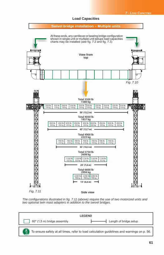
61
Fig. 7.10
Fig. 7.11
7 - LOAD CAPACITIES
Load Capacities
Swivel bridge installation – Multiple units
To ensure safety at all times, refer to load calculation guidelines and warnings on p. 56.
LEGEND
60" (1,5 m) bridge assembly Length of bridge setup
View from top
Side view
At these ends, any cantilever or bearing bridge confi guration shown in single unit or multiple unit setups load capacities charts may be installed (see fi g. 7.2 and fi g. 7.3)
50' (15,2 m)
45' (13,7 m)
25' (7,6 m)
15' (4,6 m)
35' (10,5 m)
350 lb159 kg
350 lb159 kg
350 lb159 kg
350 lb159 kg
350 lb159 kg
350 lb159 kg
350 lb159 kg
350 lb159 kg
350 lb159 kg
350 lb159 kg
Total 3500 lb1588 kg
Total 4050 lb1837 kg
450 lb204 kg
450 lb204 kg
450 lb204 kg
450 lb204 kg
450 lb204 kg
450 lb204 kg
450 lb204 kg
450 lb204 kg
450 lb204 kg
700 lb318 kg
700 lb318 kg
700 lb318 kg
700 lb318 kg
700 lb318 kg
700 lb318 kg
700 lb318 kg
Total 4900 lb2223 kg
Total 5750 lb2608 kg
1150 lb522 kg
1150 lb522 kg
1150 lb522 kg
1150 lb522 kg
1150 lb522 kg
Total 6600 lb2994 kg
2200 lb998 kg
2200 lb998 kg
2200 lb998 kg
The confi gurations illustrated in fi g. 7.11 (above) require the use of two motorized units and two optional twin mast adapters in addition to the swivel bridges.
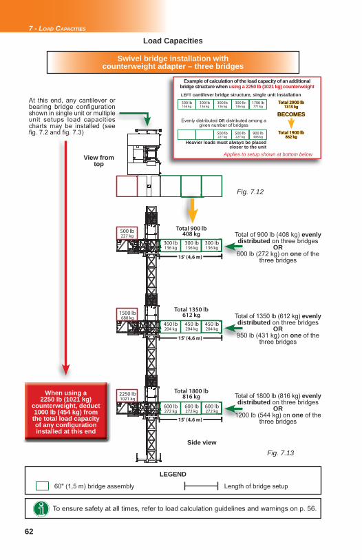
62
Fig. 7.13
Fig. 7.12
7 - LOAD CAPACITIES
Load Capacities
Swivel bridge installation with counterweight adapter – three bridges
To ensure safety at all times, refer to load calculation guidelines and warnings on p. 56.
LEGEND
60" (1,5 m) bridge assembly Length of bridge setup
View from top
Side view
300 lb136 kg
Total 900 lb408 kg
15' (4,6 m)
300 lb136 kg
300 lb136 kg
450 lb204 kg
450 lb204 kg
450 lb204 kg
600 lb272 kg
600 lb272 kg
600 lb272 kg
Total 1350 lb612 kg
15' (4,6 m)
Total 1800 lb816 kg
15' (4,6 m)
500 lb227 kg
1500 lb680 kg
2250 lb1021 kg
When using a 2250 lb (1021 kg)
counterweight, deduct 1000 lb (454 kg) from the total load capacity of any confi guration installed at this end
At this end, any cantilever or bearing bridge configuration shown in single unit or multiple unit setups load capacities charts may be installed (see fi g. 7.2 and fi g. 7.3)
Total of 900 lb (408 kg) evenly distributed on three bridges
OR 600 lb (272 kg) on one of the
three bridges
Total of 1350 lb (612 kg) evenly distributed on three bridges
OR 950 lb (431 kg) on one of the
three bridges
Total of 1800 lb (816 kg) evenly distributed on three bridges
OR 1200 lb (544 kg) on one of the
three bridges
300 lb136 kg
1700 lb771 kg
300 lb136 kg
300 lb136 kg
300 lb136 kg
Total 2900 lbTotal 2900 lb1315 kg1315 kg
Example of calculation of the load capacity of an additional bridge structure when using a 2250 lb (1021 kg) counterweight
Total 1900 lbTotal 1900 lb862 kg862 kg
Evenly distributed OR distributed among a given number of bridges
BECOMESBECOMES
LEFT cantilever bridge structure, single unit installation
900 lb408 kg
500 lb227 kg
500 lb227 kg
Heavier loads must always be placed closer to the unit
Applies to setup shown at bottom below
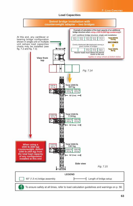
63
Fig. 7.15
Fig. 7.14
7 - LOAD CAPACITIES
Load Capacities
To ensure safety at all times, refer to load calculation guidelines and warnings on p. 56.
LEGEND
60" (1,5 m) bridge assembly Length of bridge setup
Swivel bridge installation with counterweight adapter – two bridges
View from top
Side view
1000 lb454 kg
Total 2000 lb907 kg
10' (3 m)
1000 lb454 kg
1500 lb680 kg
1000 lb454 kg
2000 lb907 kg
1000 lb454 kg
Total 2500 lb1134 kg
Total 3000 lb1361 kg
500 lb227 kg
1000 lb454 kg
1500 lb680 kg
10' (3 m)
10' (3 m)
When using a 1500 lb (680 kg)
counterweight, deduct 1000 lb (454 kg) from the total load capacity of any confi guration installed at this end
At this end, any cantilever or bearing bridge configuration shown in single unit or multiple unit setups load capacities charts may be installed (see fi g. 7.2 and fi g. 7.3)
300 lb136 kg
1700 lb771 kg
300 lb136 kg
300 lb136 kg
300 lb136 kg
Total 2900 lbTotal 2900 lb1315 kg1315 kg
Example of calculation of the load capacity of an additional bridge structure when using a 1500 lb (680 kg) counterweight
Total 1900 lbTotal 1900 lb862 kg862 kg
Evenly distributed OR distributed among a given number of bridges
BECOMESBECOMES
LEFT cantilever bridge structure, single unit installation
900 lb408 kg
500 lb227 kg
500 lb227 kg
Heavier loads must always be placed closer to the unit
Applies to setup shown at bottom below
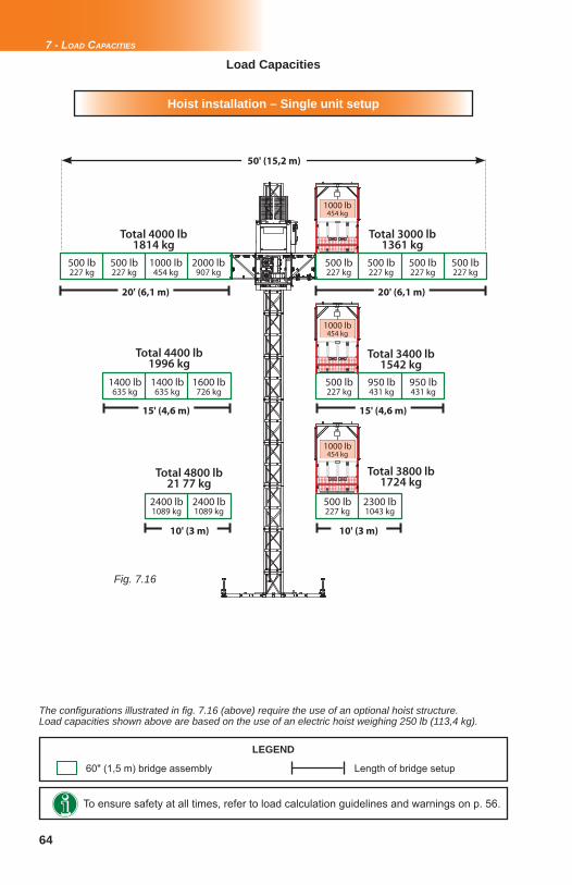
64
Fig. 7.16
7 - LOAD CAPACITIES
Load Capacities
Hoist installation – Single unit setup
To ensure safety at all times, refer to load calculation guidelines and warnings on p. 56.
LEGEND
60" (1,5 m) bridge assembly Length of bridge setup
500 lb227 kg
Total 4000 lb1814 kg
1000 lb454 kg
2000 lb907 kg
500 lb227 kg
1000 lb454 kg
1000 lb454 kg
1000 lb454 kg
500 lb227 kg
500 lb227 kg
500 lb227 kg
500 lb227 kg
50' (15,2 m)
1400 lb635 kg
1600 lb726 kg
1400 lb635 kg
Total 3000 lb1361 kg
Total 4400 lb1996 kg
Total 3400 lb1542 kg
Total 4800 lb21 77 kg
Total 3800 lb1724 kg
2400 lb1089 kg
2400 lb1089 kg
950 lb431 kg
950 lb431 kg
500 lb227 kg
2300 lb1043 kg
500 lb227 kg
20' (6,1 m)20' (6,1 m)
15' (4,6 m)15' (4,6 m)
10' (3 m)10' (3 m)
The confi gurations illustrated in fi g. 7.16 (above) require the use of an optional hoist structure. Load capacities shown above are based on the use of an electric hoist weighing 250 lb (113,4 kg).
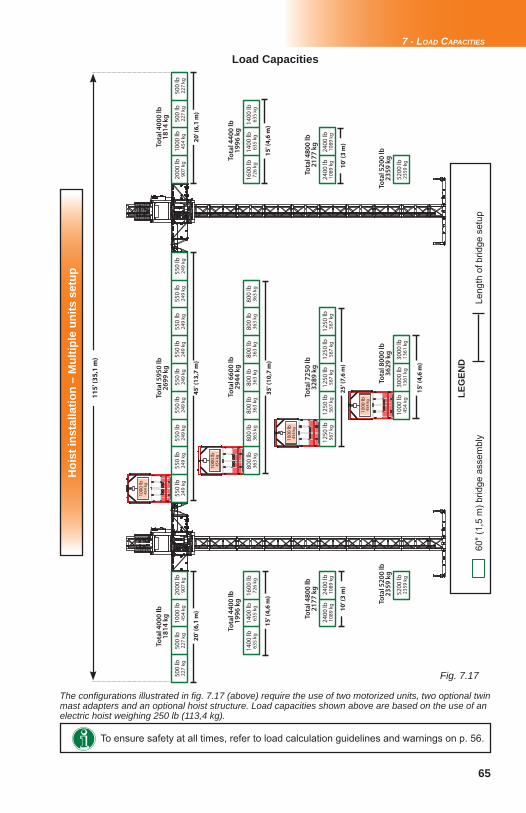
65
Fig. 7.17
7 - LOAD CAPACITIES
Load Capacities
To ensure safety at all times, refer to load calculation guidelines and warnings on p. 56.
LEG
END
60" (
1,5
m) b
ridge
ass
embl
yLe
ngth
of b
ridge
set
up
Hoi
st in
stal
latio
n –
Mul
tiple
uni
ts s
etup
1000
lb45
4 kg
1000
lb45
4 kg
1000
lb45
4 kg
1000
lb45
4 kg
500
lb22
7 kg
1000
lb45
4 kg
500
lb22
7 kg
2000
lb90
7 kg
Tota
l 400
0 lb
1814
kg
20
' (6
,1 m
)
11
5' (
35
,1 m
)
15
' (4
,6 m
)
10
' (3
m)
45
' (1
3,7
m)
35
' (1
0,7
m)
25
' (7
,6 m
)
15
' (4
,6 m
)
20
' (6
,1 m
)
15
' (4
,6 m
)
10
' (3
m)
2000
lb90
7 kg
500
lb22
7 kg
1000
lb45
4 kg
500
lb22
7 kg
550
lb24
9 kg
550
lb24
9 kg
550
lb24
9 kg
550
lb24
9 kg
550
lb24
9 kg
550
lb24
9 kg
550
lb24
9 kg
550
lb24
9 kg
550
lb24
9 kg
1400
lb63
5 kg
1600
lb72
6 kg
1400
lb63
5 kg
800
lb36
3 kg
800
lb36
3 kg
800
lb36
3 kg
800
lb36
3 kg
800
lb36
3 kg
800
lb36
3 kg
800
lb36
3 kg
1600
lb72
6 kg
1400
lb63
5 kg
1400
lb63
5 kg
2400
lb10
89 k
g24
00 lb
1089
kg
1250
lb56
7 kg
1250
lb56
7 kg
1250
lb56
7 kg
1250
lb56
7 kg
1250
lb56
7 kg
2400
lb10
89 k
g24
00 lb
1089
kg
1000
lb45
4 kg
3000
lb13
61 k
g30
00 lb
1361
kg
5200
lb23
59 k
g52
00 lb
2359
kg
Tota
l 595
0 lb
2699
kg
Tota
l 400
0 lb
1814
kg
Tota
l 660
0 lb
2944
kg
Tota
l 725
0 lb
3289
kg
Tota
l 800
0 lb
3629
kg
Tota
l 440
0 lb
1996
kg
Tota
l 440
0 lb
1996
kg
Tota
l 480
0 lb
2177
kg
Tota
l 480
0 lb
2177
kg
Tota
l 520
0 lb
2359
kg
Tota
l 520
0 lb
2359
kg
The confi gurations illustrated in fi g. 7.17 (above) require the use of two motorized units, two optional twin mast adapters and an optional hoist structure. Load capacities shown above are based on the use of an electric hoist weighing 250 lb (113,4 kg).
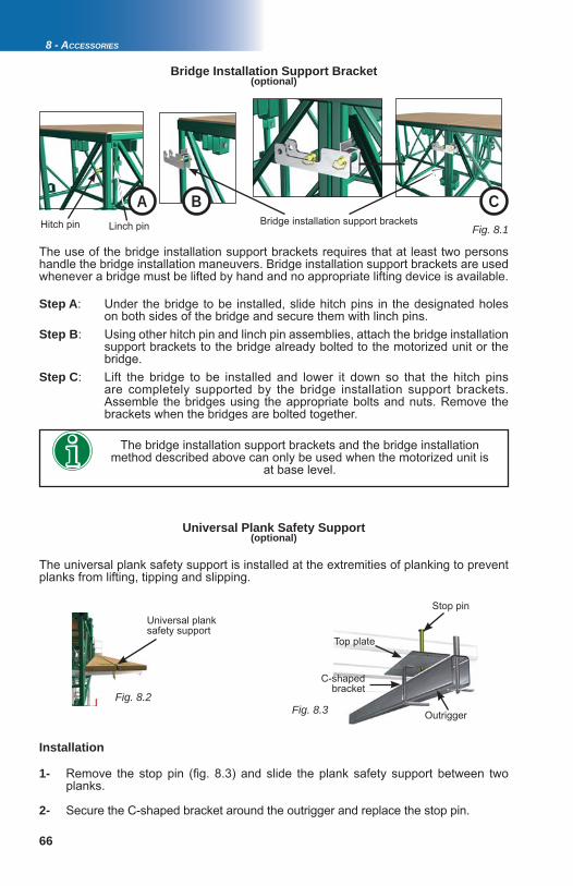
66
A B C
Fig. 8.2Fig. 8.3
Fig. 8.1
Bridge Installation Support Bracket
Step A: Under the bridge to be installed, slide hitch pins in the designated holes on both sides of the bridge and secure them with linch pins. Step B: Using other hitch pin and linch pin assemblies, attach the bridge installation support brackets to the bridge already bolted to the motorized unit or the bridge.Step C: Lift the bridge to be installed and lower it down so that the hitch pins are completely supported by the bridge installation support brackets. Assemble the bridges using the appropriate bolts and nuts. Remove the brackets when the bridges are bolted together.
The bridge installation support brackets and the bridge installation method described above can only be used when the motorized unit is
at base level.
Hitch pin Bridge installation support bracketsLinch pin
Universal Plank Safety Support
The universal plank safety support is installed at the extremities of planking to prevent planks from lifting, tipping and slipping.
Top plate
Outrigger
Stop pin
C-shaped bracket
1- Remove the stop pin (fi g. 8.3) and slide the plank safety support between two planks.
2- Secure the C-shaped bracket around the outrigger and replace the stop pin.
Installation
Universal plank safety support
8 - ACCESSORIES
(optional)
(optional)
The use of the bridge installation support brackets requires that at least two persons handle the bridge installation maneuvers. Bridge installation support brackets are used whenever a bridge must be lifted by hand and no appropriate lifting device is available.
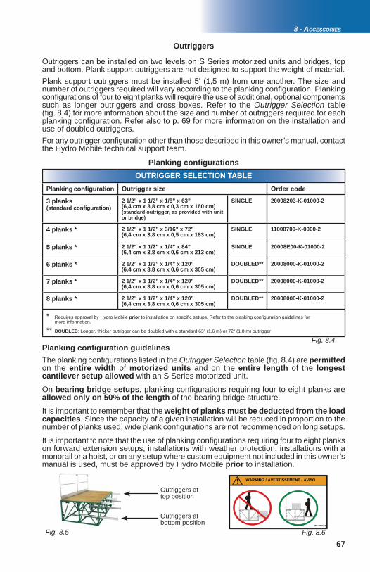
67Fig. 8.5 Fig. 8.6
Fig. 8.4
8 - ACCESSORIES
Outriggers at top position
Outriggers at bottom position
Outriggers can be installed on two levels on S Series motorized units and bridges, top and bottom. Plank support outriggers are not designed to support the weight of material. Plank support outriggers must be installed 5' (1,5 m) from one another. The size and number of outriggers required will vary according to the planking confi guration. Planking confi gurations of four to eight planks will require the use of additional, optional components such as longer outriggers and cross boxes. Refer to the Outrigger Selection table (fi g. 8.4) for more information about the size and number of outriggers required for each planking confi guration. Refer also to p. 69 for more information on the installation and use of doubled outriggers.For any outrigger confi guration other than those described in this owner’s manual, contact the Hydro Mobile technical support team.
Outriggers
OUTRIGGER SELECTION TABLEPlanking confi guration Outrigger size Order code
3 planks (standard confi guration)
2 1/2” x 1 1/2” x 1/8” x 63”(6,4 cm x 3,8 cm x 0,3 cm x 160 cm)(standard outrigger, as provided with unit or bridge)
SINGLE 20008203-K-01000-2
4 planks * 2 1/2” x 1 1/2” x 3/16” x 72”(6,4 cm x 3,8 cm x 0,5 cm x 183 cm)
SINGLE 11008700-K-0000-2
5 planks * 2 1/2” x 1 1/2” x 1/4” x 84”(6,4 cm x 3,8 cm x 0,6 cm x 213 cm)
SINGLE 20008E00-K-01000-2
6 planks * 2 1/2” x 1 1/2” x 1/4” x 120”(6,4 cm x 3,8 cm x 0,6 cm x 305 cm)
DOUBLED** 20008000-K-01000-2
7 planks * 2 1/2” x 1 1/2” x 1/4” x 120”(6,4 cm x 3,8 cm x 0,6 cm x 305 cm)
DOUBLED** 20008000-K-01000-2
8 planks * 2 1/2” x 1 1/2” x 1/4” x 120”(6,4 cm x 3,8 cm x 0,6 cm x 305 cm)
DOUBLED** 20008000-K-01000-2
* Requires approval by Hydro Mobile prior to installation on specifi c setups. Refer to the planking confi guration guidelines for more information.
** DOUBLED: Longer, thicker outrigger can be doubled with a standard 63" (1,6 m) or 72" (1,8 m) outrigger
The planking confi gurations listed in the Outrigger Selection table (fi g. 8.4) are permittedon the entire width of motorized units and on the entire length of the longest cantilever setup allowed with an S Series motorized unit.
On bearing bridge setups, planking confi gurations requiring four to eight planks are allowed only on 50% of the length of the bearing bridge structure.
It is important to remember that the weight of planks must be deducted from the load capacities. Since the capacity of a given installation will be reduced in proportion to the number of planks used, wide plank confi gurations are not recommended on long setups.
It is important to note that the use of planking confi gurations requiring four to eight planks on forward extension setups, installations with weather protection, installations with a monorail or a hoist, or on any setup where custom equipment not included in this owner’s manual is used, must be approved by Hydro Mobile prior to installation.
Planking confi gurations
Planking confi guration guidelines
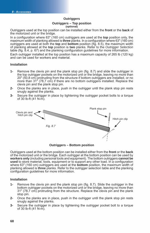
68
Fig. 8.7
8 - ACCESSORIES
Installation
Outriggers used at the top position can be installed either from the front or the back of the motorized unit or the bridge. In a confi guration where 63" (160 cm) outriggers are used at the top position only, the maximum width of planking allowed is three planks. In a confi guration where 63" (160 cm) outriggers are used at both the top and bottom position (fi g. 8.5), the maximum width of planking allowed at the top position is two planks. Refer to the Outrigger Selection table (fi g. 8.4, p. 67) and the planking confi guration guidelines for more information.Each outrigger installed at the top position has a maximum capacity of 265 lb (120 kg) and can be used for workers and material.
(optional)
Outriggers
1- Remove the clevis pin and the plank stop pin (fi g. 8.7) and slide the outrigger in the top outrigger pockets on the motorized unit or the bridge, leaving no more than 20" (50,8 cm) protruding from the structure if bottom outriggers are installed, or no more than 31" (78,7 cm) if there are no bottom outriggers installed. Replace the clevis pin and the plank stop pin.2- Once the planks are in place, push in the outrigger until the plank stop pin rests snugly against the planks. 3- Secure the outrigger in place by tightening the outrigger pocket bolts to a torque of 30 lb-ft (41 N-m).
Outriggers – Top position
Outriggers – Bottom position
Outriggers used at the bottom position can be installed either from the front or the backof the motorized unit or the bridge. Each outrigger at the bottom position can be used by workers only (including personal tools and equipment). The bottom outriggers cannot be used to store material, tools, equipment or to support any other load. In a confi guration where 63" (160 cm) outriggers are used at the bottom position, the maximum width of planking allowed is three planks. Refer to the outrigger selection table and the planking confi guration guidelines for more information.
Installation1- Remove the clevis pin and the plank stop pin (fi g. 8.7). Slide the outrigger in the bottom outrigger pockets on the motorized unit or the bridge, leaving no more than 31" (78,7 cm) protruding from the structure. Replace the clevis pin and the plank stop pin.2- Once the planks are in place, push in the outrigger until the plank stop pin rests snugly against the planks. 3- Secure the outrigger in place by tightening the outrigger pocket bolt to a torque of 30 lb-ft (41 N-m).
Plank stop pin
Hitch pin clip
Clevis pin and hitch pin clip
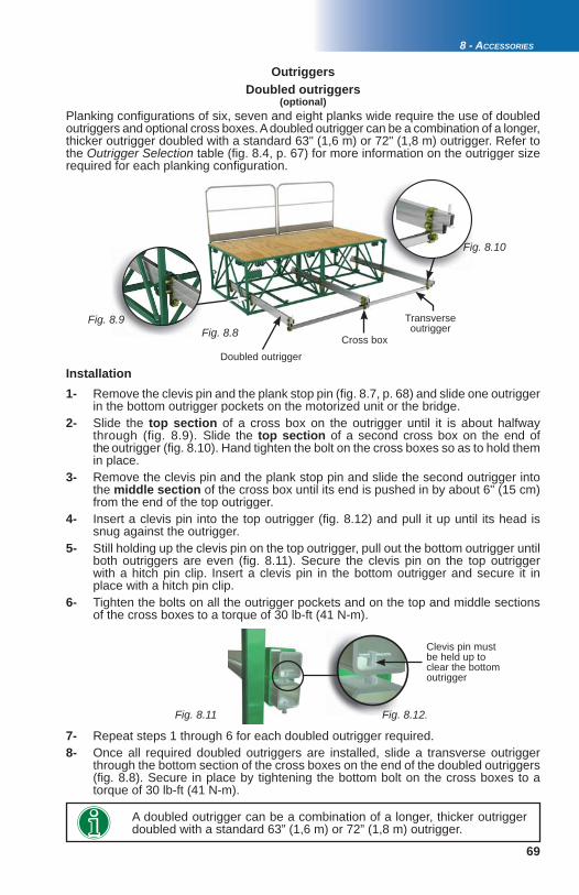
69
Fig. 8.10
Fig. 8.9
gg. gFiig
Fig. 8.8
Fig. 8.11 Fig. 8.12.
8 - ACCESSORIES
1- Remove the clevis pin and the plank stop pin (fi g. 8.7, p. 68) and slide one outrigger in the bottom outrigger pockets on the motorized unit or the bridge. 2- Slide the top section of a cross box on the outrigger until it is about halfway through (fig. 8.9). Slide the top section of a second cross box on the end of the outrigger (fi g. 8.10). Hand tighten the bolt on the cross boxes so as to hold them in place. 3- Remove the clevis pin and the plank stop pin and slide the second outrigger into the middle section of the cross box until its end is pushed in by about 6" (15 cm) from the end of the top outrigger. 4- Insert a clevis pin into the top outrigger (fi g. 8.12) and pull it up until its head is snug against the outrigger. 5- Still holding up the clevis pin on the top outrigger, pull out the bottom outrigger until both outriggers are even (fi g. 8.11). Secure the clevis pin on the top outrigger with a hitch pin clip. Insert a clevis pin in the bottom outrigger and secure it in place with a hitch pin clip. 6- Tighten the bolts on all the outrigger pockets and on the top and middle sections of the cross boxes to a torque of 30 lb-ft (41 N-m).
OutriggersDoubled outriggers
(optional)Planking confi gurations of six, seven and eight planks wide require the use of doubled outriggers and optional cross boxes. A doubled outrigger can be a combination of a longer, thicker outrigger doubled with a standard 63" (1,6 m) or 72" (1,8 m) outrigger. Refer to the Outrigger Selection table (fi g. 8.4, p. 67) for more information on the outrigger size required for each planking confi guration.
Doubled outrigger
Transverse outrigger
Cross box
7- Repeat steps 1 through 6 for each doubled outrigger required. 8- Once all required doubled outriggers are installed, slide a transverse outrigger through the bottom section of the cross boxes on the end of the doubled outriggers (fi g. 8.8). Secure in place by tightening the bottom bolt on the cross boxes to a torque of 30 lb-ft (41 N-m).
Clevis pin must be held up to clear the bottom outrigger
Installation
A doubled outrigger can be a combination of a longer, thicker outrigger doubled with a standard 63” (1,6 m) or 72” (1,8 m) outrigger.
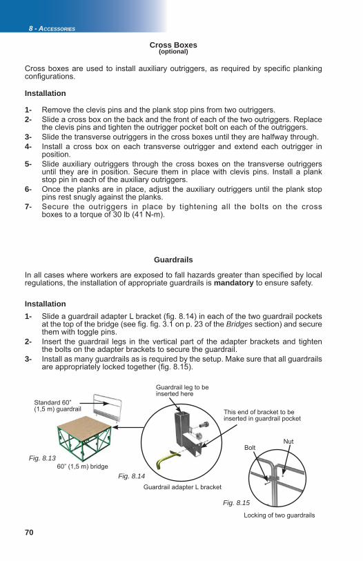
70
Fig. 8.15
Fig. 8.14
Fig. 8.13
Locking of two guardrails
60” (1,5 m) bridge
BoltNut
Guardrail adapter L bracket
Guardrail leg to be inserted here
This end of bracket to be inserted in guardrail pocket
Cross Boxes
Cross boxes are used to install auxiliary outriggers, as required by specifi c planking confi gurations.
Installation
1- Remove the clevis pins and the plank stop pins from two outriggers.2- Slide a cross box on the back and the front of each of the two outriggers. Replace the clevis pins and tighten the outrigger pocket bolt on each of the outriggers. 3- Slide the transverse outriggers in the cross boxes until they are halfway through.4- Install a cross box on each transverse outrigger and extend each outrigger in position.5- Slide auxiliary outriggers through the cross boxes on the transverse outriggers until they are in position. Secure them in place with clevis pins. Install a plank stop pin in each of the auxiliary outriggers.6- Once the planks are in place, adjust the auxiliary outriggers until the plank stop pins rest snugly against the planks. 7- Secure the outriggers in place by tightening all the bolts on the cross boxes to a torque of 30 lb (41 N-m).
Guardrails
1- Slide a guardrail adapter L bracket (fi g. 8.14) in each of the two guardrail pockets at the top of the bridge (see fi g. fi g. 3.1 on p. 23 of the Bridges section) and secure them with toggle pins. 2- Insert the guardrail legs in the vertical part of the adapter brackets and tighten the bolts on the adapter brackets to secure the guardrail. 3- Install as many guardrails as is required by the setup. Make sure that all guardrails are appropriately locked together (fi g. 8.15).
Installation
In all cases where workers are exposed to fall hazards greater than specifi ed by local regulations, the installation of appropriate guardrails is mandatory to ensure safety.
Standard 60”(1,5 m) guardrail
(optional)
8 - ACCESSORIES
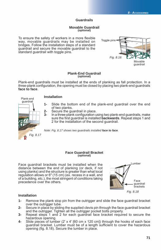
71
Fig. 8.16
Fig. 8.17
8 - ACCESSORIES
Fig. 8.18
Face guardrail brackets
Plank-end guardrail
Installation
1- Slide the bottom end of the plank-end guardrail over the end of two planks.2- Secure the guardrail in place. 3- In a three-plank confi guration using two plank-end guardrails, make sure the fi rst guardrail is installed backwards. Repeat steps 1 and 2 for the installation of the second guardrail.
Movable Guardrail
Toggle pins
Face guardrail brackets must be installed when the distance between the end of planking (or deck, if not using planks) and the structure is greater than what local regulation allows or 6" (15 cm) (ex. recess in a wall, end of a building, etc.), the most stringent of conditions taking precedence over the others.
Plank-end guardrails must be installed at the ends of planking as fall protection. In a three-plank confi guration, the opening must be closed by placing two plank-end guardrails face to face.
Installation1- Remove the plank stop pin from the outrigger and slide the face guardrail bracket over the outrigger tube. 2- Secure in place by sliding the supplied clevis pin through the face guardrail bracket and the outrigger. Tighten all the outrigger pocket bolts properly.3- Repeat steps 1 and 2 for each guardrail face bracket required to secure the hazardous opening. 4- Slide pieces of lumber (2' x 4' [60 cm x 120 cm]) through the hooks of each face guardrail bracket. Lumber must be of a length suffi cient to cover the hazardous opening (fi g. 8.18). Secure the lumber in place.
To ensure the safety of workers in a more fl exible way, movable guardrails may be installed on bridges. Follow the installation steps of a standard guardrail and secure the movable guardrail to the standard guardrail with toggle pins.
Plank-End Guardrail
Face Guardrail Bracket
Lumber
Movable guardrail
Note: Fig. 8.17 shows two guardrails installed face to face.
Guardrails
(optional)
(optional)
(optional)
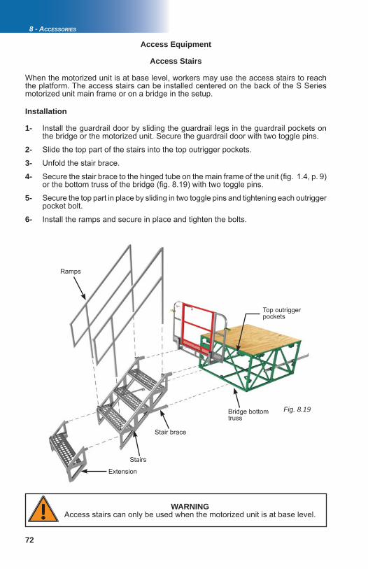
72
Fig. 8.19
1- Install the guardrail door by sliding the guardrail legs in the guardrail pockets on the bridge or the motorized unit. Secure the guardrail door with two toggle pins.
2- Slide the top part of the stairs into the top outrigger pockets.
3- Unfold the stair brace.
4- Secure the stair brace to the hinged tube on the main frame of the unit (fi g. 1.4, p. 9) or the bottom truss of the bridge (fi g. 8.19) with two toggle pins.
5- Secure the top part in place by sliding in two toggle pins and tightening each outrigger pocket bolt.
6- Install the ramps and secure in place and tighten the bolts.
Access Stairs
When the motorized unit is at base level, workers may use the access stairs to reach the platform. The access stairs can be installed centered on the back of the S Series motorized unit main frame or on a bridge in the setup.
Installation
Stair brace
Ramps
Top outrigger pockets
Bridge bottom truss
WARNINGAccess stairs can only be used when the motorized unit is at base level.
Access Equipment
8 - ACCESSORIES
Stairs
Extension
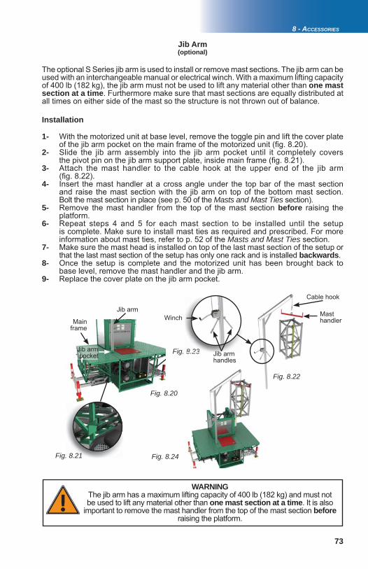
73
Fig. 8.24
Fig. 8.23
Fig. 8.22
8 23
Fig. 8.20
Fig. 8.21
8 - ACCESSORIES
Jib Arm
1- With the motorized unit at base level, remove the toggle pin and lift the cover plate of the jib arm pocket on the main frame of the motorized unit (fi g. 8.20).2- Slide the jib arm assembly into the jib arm pocket until it completely covers the pivot pin on the jib arm support plate, inside main frame (fi g. 8.21). 3- Attach the mast handler to the cable hook at the upper end of the jib arm (fi g. 8.22).4- Insert the mast handler at a cross angle under the top bar of the mast section and raise the mast section with the jib arm on top of the bottom mast section. Bolt the mast section in place (see p. 50 of the Masts and Mast Ties section).5- Remove the mast handler from the top of the mast section before raising the platform.6- Repeat steps 4 and 5 for each mast section to be installed until the setup is complete. Make sure to install mast ties as required and prescribed. For more information about mast ties, refer to p. 52 of the Masts and Mast Ties section. 7- Make sure the mast head is installed on top of the last mast section of the setup or that the last mast section of the setup has only one rack and is installed backwards. 8- Once the setup is complete and the motorized unit has been brought back to base level, remove the mast handler and the jib arm.9- Replace the cover plate on the jib arm pocket.
WARNINGThe jib arm has a maximum lifting capacity of 400 lb (182 kg) and must not be used to lift any material other than one mast section at a time. It is also
important to remove the mast handler from the top of the mast section before raising the platform.
The optional S Series jib arm is used to install or remove mast sections. The jib arm can be used with an interchangeable manual or electrical winch. With a maximum lifting capacity of 400 lb (182 kg), the jib arm must not be used to lift any material other than one mast section at a time. Furthermore make sure that mast sections are equally distributed at all times on either side of the mast so the structure is not thrown out of balance.
Installation
(optional)
Jib arm handles
Winch
Jib arm pocket
Main frame
Mast handler
Jib arm
Cable hook
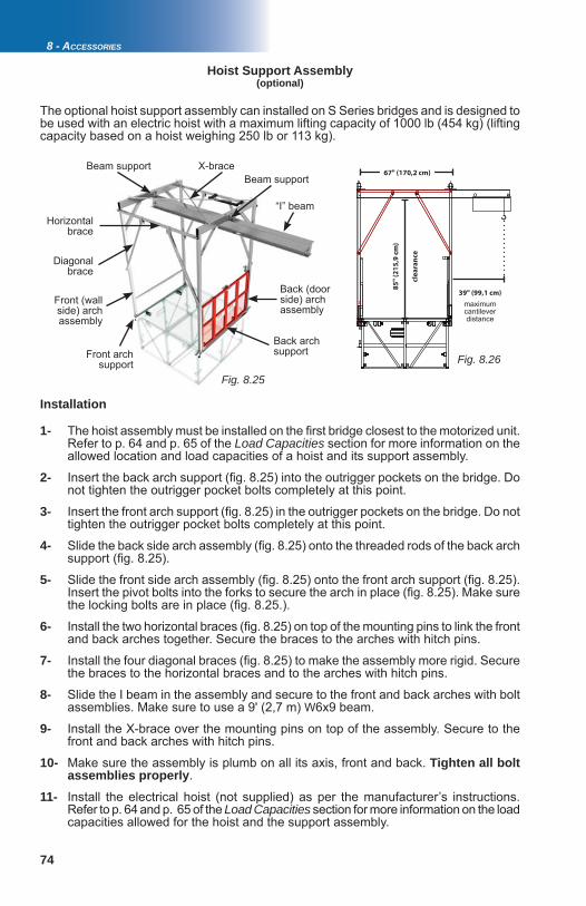
74
Fig. 8.25
Fig. 8.26
8 - ACCESSORIES
Hoist Support Assembly
The optional hoist support assembly can installed on S Series bridges and is designed to be used with an electric hoist with a maximum lifting capacity of 1000 lb (454 kg) (lifting capacity based on a hoist weighing 250 lb or 113 kg).
X-brace
“I” beam
Diagonal brace
Horizontal brace
Front (wall side) arch assembly
Back (door side) arch assembly
Front arch support
Back arch support
Beam supportBeam support
Installation
1- The hoist assembly must be installed on the fi rst bridge closest to the motorized unit. Refer to p. 64 and p. 65 of the Load Capacities section for more information on the allowed location and load capacities of a hoist and its support assembly.
2- Insert the back arch support (fi g. 8.25) into the outrigger pockets on the bridge. Do not tighten the outrigger pocket bolts completely at this point.
3- Insert the front arch support (fi g. 8.25) in the outrigger pockets on the bridge. Do not tighten the outrigger pocket bolts completely at this point.
4- Slide the back side arch assembly (fi g. 8.25) onto the threaded rods of the back arch support (fi g. 8.25).
5- Slide the front side arch assembly (fi g. 8.25) onto the front arch support (fi g. 8.25). Insert the pivot bolts into the forks to secure the arch in place (fi g. 8.25). Make sure the locking bolts are in place (fi g. 8.25.).
6- Install the two horizontal braces (fi g. 8.25) on top of the mounting pins to link the front and back arches together. Secure the braces to the arches with hitch pins.
7- Install the four diagonal braces (fi g. 8.25) to make the assembly more rigid. Secure the braces to the horizontal braces and to the arches with hitch pins.
8- Slide the I beam in the assembly and secure to the front and back arches with bolt assemblies. Make sure to use a 9' (2,7 m) W6x9 beam.
9- Install the X-brace over the mounting pins on top of the assembly. Secure to the front and back arches with hitch pins.
10- Make sure the assembly is plumb on all its axis, front and back. Tighten all bolt assemblies properly.
11- Install the electrical hoist (not supplied) as per the manufacturer’s instructions. Refer to p. 64 and p. 65 of the Load Capacities section for more information on the load capacities allowed for the hoist and the support assembly.
67" (170,2 cm)
85
" (2
15
,9 c
m)
cle
ara
nce
39" (99,1 cm)
maximum cantilever distance
(optional)
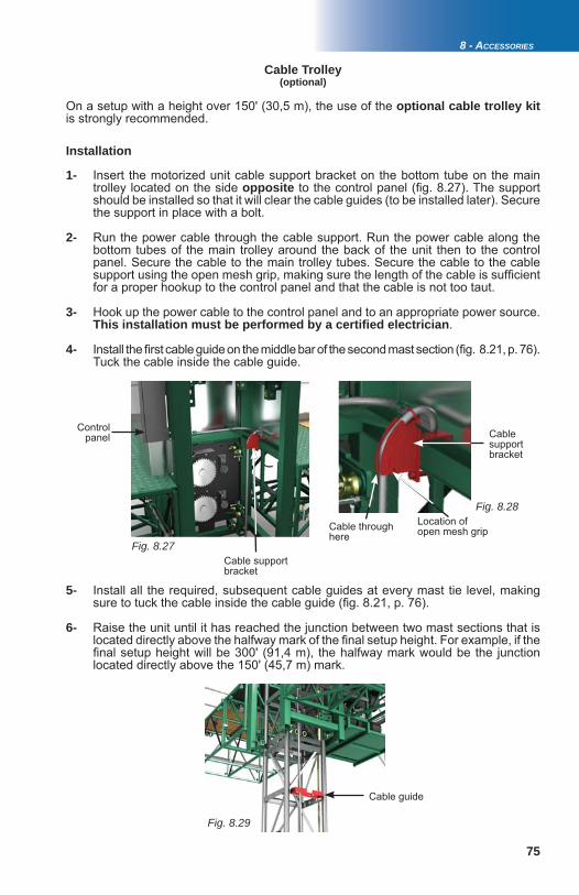
75
Fig. 8.27
Fig. 8.28
Fig. 8.29
8 - ACCESSORIES
Installation
1- Insert the motorized unit cable support bracket on the bottom tube on the main trolley located on the side opposite to the control panel (fi g. 8.27). The support should be installed so that it will clear the cable guides (to be installed later). Secure the support in place with a bolt.
2- Run the power cable through the cable support. Run the power cable along the bottom tubes of the main trolley around the back of the unit then to the control panel. Secure the cable to the main trolley tubes. Secure the cable to the cable support using the open mesh grip, making sure the length of the cable is suffi cient for a proper hookup to the control panel and that the cable is not too taut.
3- Hook up the power cable to the control panel and to an appropriate power source. This installation must be performed by a certifi ed electrician.
4- Install the fi rst cable guide on the middle bar of the second mast section (fi g. 8.21, p. 76). Tuck the cable inside the cable guide.
5- Install all the required, subsequent cable guides at every mast tie level, making sure to tuck the cable inside the cable guide (fi g. 8.21, p. 76).
6- Raise the unit until it has reached the junction between two mast sections that is located directly above the halfway mark of the fi nal setup height. For example, if the fi nal setup height will be 300' (91,4 m), the halfway mark would be the junction located directly above the 150' (45,7 m) mark.
Location of open mesh grip
Cable support bracket
Cable through here
Cable Trolley(optional)
On a setup with a height over 150' (30,5 m), the use of the optional cable trolley kitis strongly recommended.
Cable support bracket
Control panel
Cable guide
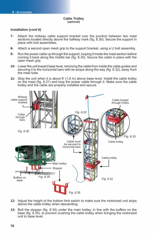
76
Fig. 8.30
Fig. 8.31
Fig. 8.33
Fig. 8.32
Fig. 8.35
Fig. 8.35
8 - ACCESSORIES
Installation (cont’d)
Cable Trolley
7- Attach the midway cable support bracket over the junction between two mast sections located directly above the halfway mark (fi g. 8.30). Secure the support in place with bolt assemblies.
8- Attach a second open mesh grip to the support bracket, using a U bolt assembly.
9- Run the power cable up through the support, looping it inside the mast section before running it back along the middle bar (fi g. 8.30). Secure the cable in place with the open mesh grip.
10- Lower the unit toward base level, removing the cable from inside the cable guides and securing it to the horizontal bars with tie wraps along the way (fi g. 8.32), away from the mast tube.
11- Stop the unit when it is about 6' (1,8 m) above base level. Install the cable trolley on the mast (fi g. 8.31) and loop the power cable through it. Make sure the cable trolley and the cable are properly installed and secure.
Midway cable support
bracket
Cable through
here
Cable trolley
Cable trolley
Cable must be secured to
horizontal bars
Cable looped through trolley
(optional)
12- Adjust the height of the bottom limit switch to make sure the motorized unit stops above the cable trolley when descending.
13- Bolt the stopper (fi g. 8.34) under the main trolley, in line with the buffers on the base (fi g. 8.35), to prevent crushing the cable trolley when bringing the motorized unit to base level.
Buffers on base
Main trolley
Stopper
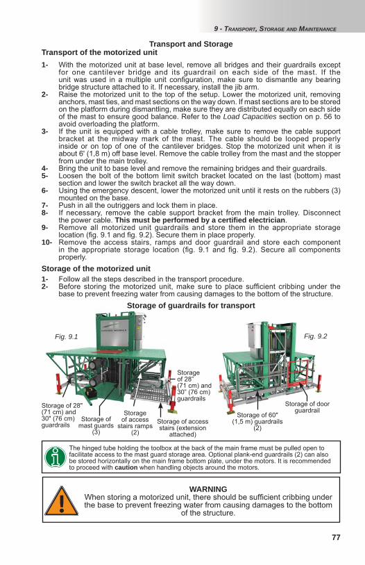
77
Fig. 9.1 Fig. 9.2
The hinged tube holding the toolbox at the back of the main frame must be pulled open to facilitate access to the mast guard storage area. Optional plank-end guardrails (2) can also be stored horizontally on the main frame bottom plate, under the motors. It is recommended to proceed with caution when handling objects around the motors.
1- With the motorized unit at base level, remove all bridges and their guardrails except for one cantilever bridge and its guardrail on each side of the mast. If the unit was used in a multiple unit confi guration, make sure to dismantle any bearing bridge structure attached to it. If necessary, install the jib arm. 2- Raise the motorized unit to the top of the setup. Lower the motorized unit, removing anchors, mast ties, and mast sections on the way down. If mast sections are to be stored on the platform during dismantling, make sure they are distributed equally on each side of the mast to ensure good balance. Refer to the Load Capacities section on p. 56 to avoid overloading the platform.3- If the unit is equipped with a cable trolley, make sure to remove the cable support bracket at the midway mark of the mast. The cable should be looped properly inside or on top of one of the cantilever bridges. Stop the motorized unit when it is about 6' (1,8 m) off base level. Remove the cable trolley from the mast and the stopper from under the main trolley. 4- Bring the unit to base level and remove the remaining bridges and their guardrails.5- Loosen the bolt of the bottom limit switch bracket located on the last (bottom) mast section and lower the switch bracket all the way down. 6- Using the emergency descent, lower the motorized unit until it rests on the rubbers (3) mounted on the base.7- Push in all the outriggers and lock them in place. 8- If necessary, remove the cable support bracket from the main trolley. Disconnect the power cable. This must be performed by a certifi ed electrician. 9- Remove all motorized unit guardrails and store them in the appropriate storage location (fi g. 9.1 and fi g. 9.2). Secure them in place properly.10- Remove the access stairs, ramps and door guardrail and store each component in the appropriate storage location (fi g. 9.1 and fi g. 9.2). Secure all components properly.
Transport of the motorized unit
Storage of the motorized unit1- Follow all the steps described in the transport procedure.2- Before storing the motorized unit, make sure to place suffi cient cribbing under the base to prevent freezing water from causing damages to the bottom of the structure.
WARNINGWhen storing a motorized unit, there should be suffi cient cribbing under the base to prevent freezing water from causing damages to the bottom
of the structure.
Transport and Storage
Storage of 28" (71 cm) and 30" (76 cm) guardrails
Storage of mast guards
(3)Storage of access stairs (extension
attached)
Storage of 28” (71 cm) and 30” (76 cm) guardrails
Storage of access
stairs ramps(2)
Storage of guardrails for transport
Storage of 60" (1,5 m) guardrails
(2)
Storage of door guardrail
9 - TRANSPORT, STORAGE AND MAINTENANCE

78
Fig. 9.3
Maintenance
Proper maintenance and service will warrant safe, economical, and trouble-free operation of S Series motorized units and their accessories. Daily inspections and maintenance operations must be performed by a competent person. Frequent inspections and maintenance operations must be carried out by an authorized technician specifi cally trained on S Series motorized units and equipment and their accessories. Yearly inspections must be performed by a certifi ed technician. Daily and frequent inspection operations are only necessary when the motorized unit and its accessories are in use. The owner and/or user is responsible for all inspection and maintenance operations. Before being fi rst used on a job site, an S Series motorized unit and its accessories must be inspected effectively and timely, according to the schedules recommended for S Series motorized units and their accessories.In order to ensure operational safety and avoid failures, the owner must make sure that all the scheduled inspection and maintenance operations have been effectively and timely carried out according to the inspection and maintenance schedules recommended for S Series motorized units and their accessories. Blank copies of the daily and frequent inspection checklists should be available on job sites at all times to be fi lled out when these inspection operations are carried out. Maintenance and inspection logs must be kept on record for warranty and safety purposes. Copies of all the inspection and maintenance checklists recommended for S Series motorized units and their accessories can be downloaded directly from the Hydro Mobile website at www.hydro-mobile.com. Copies of these checklists can also be obtained by contacting the service center of the Hydro Mobile technical support team.
9 - TRANSPORT, STORAGE AND MAINTENANCE
A proper and timely greasing of the gears and the rack is critical to guarantee performance and longevity of the Hydro Mobile S Series mast climber system. It is important to understand that not all open gear greases and lubricants offer equal levels of quality and performance. Consequently, only open gear grease approved by the Hydro Mobile Engineering department should be used on Hydro Mobile equipment.
Application frequency must be based on the installation and the cumulative runtime use of the equipment. However, the gears and racks should typically be greased after every 8 to 10 hours of operation (with unit traveling up and down the mast).
Gears and racks on a typical mast climber with a duty cycle of 25% will require to be greased on a weekly basis
8 hrs/day * 5 days * 25% duty cycle = 10 hrs Higher duty cycle operation will require greasing to be more frequent. For example, use of the S Series mast climber in a transport platform application in 100% duty cycle will increase greasing requirements to up to once a day.
Grease must be applied to the rack and gears at the end of the working shift , from the top of the setup down. Grease must be allowed to stand for 2-3 hours before the motorized unit is used again. Use an open gear lubricant recommended by Hydro Mobile.
Old grease expelled out of the gear meshing should be cleaned off on a regular basis. The rack should be visually inspected at the end of each working shift and grease should be applied if needed.
Greasing of gears and rack
Recommended open gear lubricantsManufacturer Part numberProlab OG-700
Petron Corporation Gear Shield NC
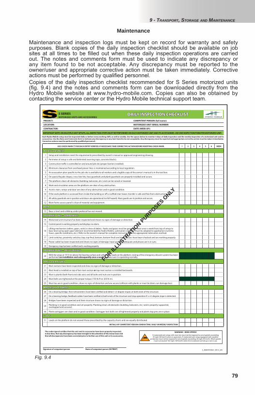
79
Fig. 9.4
9 - TRANSPORT, STORAGE AND MAINTENANCE
Maintenance
PROJECT: COMPETENT PERSON (full name):
LOCATION: MOTORIZED UNIT SERIAL NUMBER:
CONTRACTOR: DATE (WEEK OF):
Each Hydro Mobile setup must be inspected daily or before every working shift, as well as weekly. Use the spaces below to monitor 6 days of daily inspection and the weekly inspection of a motorized unit and its
accessories. Use the Notes and Comments form to indicate any discrepancy or any item found to be not acceptable. Any discrepancy must be reported and appropriate corrective action must be taken immediately.
Corrective actions must be performed by qualifi ed personnel.
IMPORTANT NOTE: ON MULTIPLE UNIT SETUPS, ALL INSPECTION STEPS MUST BE PERFORMED ON EACH MOTORIZED UNIT AND ITS ACCESSORIES. USE ONE INSPECTION FORM PER MOTORIZED UNIT.
USE CHECK MARK FOR EACH ENTRY VERIFIED. IF NECESSARY, TAKE CORRECTIVE ACTION BEFORE INSERTING CHECK MARK. 1 2 3 4 5 6 WEEK
ACCESS and SAFETYACCESS and SAFETY
1 Setup and installation meet the requirements prescribed by owner’s manual or approved engineering drawing.
2 Perimeter of setup is safe and delimited (warning tape, concrete blocks).
3 Construction traffi c is controlled on and around job site (proper barriers installed).
4 Minimum clearance from overhead power lines is maintained according to local regulation.
5 An evacuation plan specifi c to the job site is available to all workers and a legible copy of the owner’s manual is in the tool box.
6 On special façade shapes, cross box kits, face guardrails and plank guardrails are properly installed and secure.
7 The platform clears all obstacles (building, balconies, etc.) and can be raised or lowered.
8 Work and circulation areas on the platform are clear of any obstruction.
9 Access stairs, ramps and door are clear of any obstruction and in good condition.
10 If the work platform is accessed from inside the building or off a scaff old stair tower, transfer is safe and free from obstruction.
11 All safety guardrails are in position and doors are operational (no fall hazard). Mast guards are in position and secure.
12 Main frame access panel is clear of material and equipment.
BASEBASE
13 Base is level and cribbing under pedestal has not moved.
MOTORIZED UNIT – COMPONENTSMOTORIZED UNIT – COMPONENTS
14 Motorized unit structure has been inspected and shows no signs of damage or distortion.
15 Control panel is working properly and displays no alarm.
16Lifting mechanism (rollers, gears, racks) is clear of debris. Racks and gears must be greased at least once a week from top of setup to base level using open-gear lubricant recommended by Hydro Mobile. Lubrication schedule must be adapted to application (runtime hours, specifi c conditions, etc.). Refer to the owner’s manual for complete instructions on the appropriate lubrication method.
17 Limit switches, proximity switches (top, top fi nal, bottom, bottom fi nal) and door sensors have been checked and are working properly.
18 Power cable has been inspected and shows no signs of damage. Input power is adequate and phases are is in sync.
19 Emergency stop has been verifi ed and is working properly.
MOTORIZED UNIT – SAFETY DEVICESMOTORIZED UNIT – SAFETY DEVICES
20 With the setup at 10’ (3 m) above the bearing surface and without any loads on the platform, testing of the emergency descent system has been performed (on installation and subsequently once a week) to make sure it is operating normally.
MAST and MAST TIESMAST and MAST TIES
21 Mast sections have been inspected and show no signs of damage or distortion.
22 Mast head is installed on top of last mast section or top mast section is installed backwards.
23 Mast is plumb (both front and side axis) and all bolts and nuts are in position.
24 Mast bolts are tightened at the proper torque (150 lb-ft or 203 N-m).
25 Mast ties are in good condition, show no signs of distortion and are secure (collision with planks or mast tie doors can damage ties).
BRIDGES and PLANKINGBRIDGES and PLANKING
26 On a bearing bridge, the inclinometers have been verifi ed and detect ±2-degree slopes at both ends of the structure.
27 On a bearing bridge, feedback cables have been verifi ed at both ends of the structure and stop operation if a ±5-degree slope is detected.
28 Bridges have been inspected and their structure shows no signs of damage or distortion.
29 Planking is in good condition and set properly. Planking clears all obstacles (building, balconies, etc.) and is properly supported, overlapped and secured.
30 Plank outriggers are clean and in good condition. Outrigger lock bolts are all tightened properly and plank stop pins are in place.
LOADSLOADS
31 Loads on the platform do not exceed those prescribed by the capacity charts and are equally distributed.
INITIALS OF COMPETENT PERSON CONDUCTING DAILY OR WEEKLY INSPECTION
WARNING - WIND SPEEDS
A motorized unit setup with mast ties must not be exposed to wind speeds exceeding 35 mph (56 km/h) when in operation. A motorized unit setup equipped with weather
protection must not be exposed to wind speeds exceeding 28 mph (45 km/h). Wind speeds must not exceed 102 mph (164 km/h) when the motorized unit setup is not in use.
S_MAINTDAILY_0513_EN
The undersigned certifi es that this unit and its accessories have been properly inspected,
in due time, that any discrepancy has been brought to the attention of the owner/user and
that all discrepancies have been corrected prior to further use of this unit or its accessories.
Signature of competent person Name of competent person (IN PRINT)
DAILY INSPECTION CHECKLISTDAILY INSPECTION CHECKLISTS SERIESMOTORIZED UNITS AND ACCESSORIES
Maintenance and inspection logs must be kept on record for warranty and safety purposes. Blank copies of the daily inspection checklist should be available on job sites at all times to be fi lled out when these daily inspection operations are carried out. The notes and comments form must be used to indicate any discrepancy or any item found to be not acceptable. Any discrepancy must be reported to the owner/user and appropriate corrective action must be taken immediately. Corrective actions must be performed by qualifi ed personnel.Copies of the daily inspection checklist recommended for S Series motorized units (fi g. 9.4) and the notes and comments form can be downloaded directly from the Hydro Mobile website at www.hydro-mobile.com. Copies can also be obtained by contacting the service center or the Hydro Mobile technical support team.
FOR ILLUSTRATIO
N PURPOSES ONLY
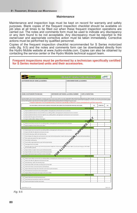
80
Fig. 9.5
Maintenance
AUTHORIZED DEALER NAME and ADDRESS: USER/OWNER NAME and ADDRESS:
USE CHECK MARK FOR EACH ENTRY VERIFIED. IF NECESSARY, TAKE CORRECTIVE ACTION BEFORE INSERTING CHECK MARK. OK CORRECTED N/A
BASE BASE
1 Inspect pedestal structure for any welding defects, damaged parts and excessive rust or corrosion.
2 Inspect pedestal extension structure (left) for any welding defects, damaged parts and excessive rust or corrosion.
3 Inspect pedestal extension structure (right) for any welding defects, damaged parts and excessive rust or corrosion.
4 Inspect jack (4x) gears and mechanism.
5 Inspect rubber buff ers. Replace if damaged.
MAIN FRAMEMAIN FRAME
6 Inspect main frame structure for any welding defects, damaged parts and excessive rust or corrosion.
7 Inspect integrity of main frame access door.
POWER TRAINPOWER TRAIN
8 Inspect power train structure for any welding defects, damaged parts and excessive rust or corrosion.
9 Inspect all rollers for alignment and excessive wear.
10 Check the bearings, shafts and retaining rings.
11 Check all gears for alignment and excessive wear as per technical procedure. Inspect retaining rings and keyway as per technical procedure.
12 Clean open gear grease from gear and pinion.
13 Check idlers and bearing.
14 Check safety angle adjustment as per technical procedure.
15 Check gear box for any leaks.
16 Check the gear box oil level as per technical procedure. Replenish, if necessary. Replace oil if over 1000 h since last oil change (or after 500 h for the break-in period).
17 Inspect brakes on upper motor as per technical procedure.
18 Inspect brakes on lower motor as per technical procedure.
19 Inspect electrical wiring to and from motors and brakes.
MAIN TROLLEYMAIN TROLLEY
20 Inspect main trolley structure for any welding defects, damaged parts and excessive rust or corrosion.
21 Inspect all rollers for alignment and excessive wear.
22 Check bearings, shafts and retaining rings.
23 Check skate rollers and make sure they pivot on the shaft.
24 Check main frame connection points and hardware.
25 Inspect electrical wiring and connection to all sensors and connectors.
26 Check electrical connection to the control panel.
27 Inspect all four (4) tie points (D-rings) on the main trolley.
CONTROL PANELCONTROL PANEL
28 Inspect electrical cord and connection port.
29 Check electrical connections inside the control panel.
30 Check control panel switches and screen.
S_MAINTFREQ_0513_EN
NAME of AUTHORIZED TECHNICIAN: MOTORIZED UNIT MODEL and SERIAL NUMBER DATE of INSPECTION:
SERIAL NUMBER
SERIAL NUMBER
SERIAL NUMBER
SERIAL NUMBER
PAGE 1 OF 3
FREQUENT INSPECTION CHECKLISTFREQUENT INSPECTION CHECKLIST
Each Hydro Mobile setup must be submitted to a frequent inspection. Use the spaces below to monitor inspections that need to be performed every three months. Use the Notes and Comments form to
indicate any discrepancy or any item found to be not acceptable. Any discrepancy must be reported and appropriate corrective action must be taken immediately. Corrective actions must be performed by qualifi ed
personnel. All inspection steps included in the daily inspection checklist must be performed before the frequent inspection steps.
S SERIESMOTORIZED UNITS AND ACCESSORIES
SERIAL NUMBER
Frequent inspections must be performed by a technician specifi cally certifi ied for S Series motorized units and their accessories.
Maintenance and inspection logs must be kept on record for warranty and safety purposes. Blank copies of the frequent inspection checklist should be available on job sites at all times to be fi lled out when these frequent inspection operations are carried out. The notes and comments form must be used to indicate any discrepancy or any item found to be not acceptable. Any discrepancy must be reported to the owner/user and appropriate corrective action must be taken immediately. Corrective actions must be performed by qualifi ed personnel.Copies of the frequent inspection checklist recommended for S Series motorized units (fi g. 9.5) and the notes and comments form can be downloaded directly from the Hydro Mobile website at www.hydro-mobile.com. Copies can also be obtained by contacting the service center or the Hydro Mobile technical support team.
FOR ILLUSTRATIO
N PURPOSES ONLY
9 - TRANSPORT, STORAGE AND MAINTENANCE
Frequent inspections must be performed by a technician specifi cally certifi ed for S Series motorized units and their accessories.